fpr30xx mamba 10 super pnp english low-res - flex...
TRANSCRIPT

DESIGNED BY

1
ATTENTIONBEFORE CONTINUING WITH THIS INSTRUCTION MANUAL OR ASSEMBLY OF YOUR MAMBA 10, PLEASE VISIT OUR WIKI SUPPORT SITE FOR THE LATEST PRODUCT UPDATES , FEATURE CHANGES, MANUAL ADDENDUMS AND FIRMWARE CHANGES FOR BOTH YOUR MAMBA 10 AND THE INSTALLED AURA 8 ADVANCED FLIGHT CONTROL SYSTEM.
http://wiki.�exinnovations.com/wiki/Mamba10http://wiki.�exinnovations.com/wiki/Aura

TABLE OF CONTENTSIntroduction ......................................................................................2Box Contents ....................................................................................2Speci�cations....................................................................................3Replacement Parts Listing............................................................3Optional Completion Items.........................................................3Completion Items ..........................................................................3Battery Charging Guidelines .......................................................3Special Language De�nitions .....................................................4Important Information Regarding Warranty.........................4Safety Warnings and Precautions..............................................4Low Voltage.......................................................................................4Main Landing Gear Installation..................................................5Tailwheel Installation .....................................................................5Horizontal Stabilizer Installation................................................6Transmitter Setup............................................................................7Aura 8 ACFS .......................................................................................7Receiver Installation/Servo Connections................................8
Connecting Battery/Arming ESC ...............................................9Main Wing Installation.................................................................10Control Direction Test ..................................................................12Flight Control Direction Sensing Test.....................................13Linkage Setup.................................................................................14Propeller/Spinner Installation...................................................14Battery Installation........................................................................15Center of Gravity............................................................................15Flying your Mamba 10.................................................................16Advanced Mamba 10 Setup.....................................................17Airframe Repairs ............................................................................18Replacing Servos ...........................................................................18Servicing the Power System......................................................19Optional Wheelpant Removal ..................................................19Aircraft Troubleshooting Guide................................................20Limited Warranty...........................................................................21AMA Safety Code...........................................................................22
BOX CONTENTS
INTRODUCTIONBiplanes o�er a unique challenge as every aspect of the design must be optimized, from the structure, to the aerodynamics, and control system.
Only years of experience designing aircraft in this category can produce the Mamba 10's aggressive, yet forgiving characteristics. Designer Quique Somenzini knows how to optimize biplane aerodynamics like no other, having won F3A and 3D world championships with his biplane designs. A biplane with less coupling or better manners cannot be found. The structure is highly optimized o�ering an aircraft that is sti� and strong, yet light in weight.
Couple a phenomenal airframe with the Aura 8 Advanced Flight Control System, the latest in stabilization technology, and you get an incredible performance package; one that remains stable, yet maneuverable. Pilots rave about its direct and non-interfering feeling, and its ability to bring out the best in aircraft.
2
§ Available in red/silver and green/silver schemes
§ Advanced Aura 8 Control System
§ SIX Servos included! FOUR for Ailerons
§ Innovative plywood sub-frame connects the motor securely to the fuselage while providing superior battery mounting and cooling
§ Extreme 3D Performance
§ Light wing loading for easy handling
§ Large control surfaces for excellent maneuverability
§ Factory-installed Shark Teeth for low speed control
§ Precise aerobatics with minimal control coupling
§ Easy disassembly for transport in small cars

3
FPM3270A Mamba 10 Super PNP Green
FPM3270B Mamba 10 Super PNP Red
FPM327001 Mamba 10 Fuselage
FPM327002 Mamba 10 Wing Set w/Struts
FPM327003 Mamba 10 Tail set
FPM327004 Mamba 10 Hatch set
FPM327005 Mamba 10 Landing gear set
FPM327006 Mamba 10 Stab Tube Joiner Cabane Tube Set
FPM327007 Mamba 10 Pushrod set
FPM327008 Mamba 10 Green/Blue Decal Set
FPM327009 Mamba 10 Red/Black Decal set
FPM327010 Mamba 10 Spinner 50mm
FPM327011 Mamba 10 Hardware Package
FPZM1010C Potenza 10 1400 Kv BL Motor
HW-BQ8015 Hobby Wing 50A Skywalker 5A BEC
FPZDS15 Potenza DS15 Digital Sub-Micro Servo
FPZA1015 Servo Custom Y-Harness (Mamba 10)
FPZAURA08ZZM10 Aura 8 for Mamba 10
REPLACEMENT PARTS LISTING
The assembly of the Mamba 10 can be accomplished in less than one hour. Prior to assembling the airplane, it is advisable to charge your battery so that you are ready to begin setup upon completion of the assembly of your model.
We recommend the use of an advanced LiPo balancing charger, such as our Potenza C80 Multi Chemistry Touch Screen AC/DC balancing charger for your batteries to get the maximum performance and lifespan from them.
Our airplanes are designed around our Potenza LiPo batteries and we recommend the Potenza 3S 2200mAh 45C LiPo and the 4S 2200mAh 40C LiPo in the Mamba 10 based on our extensive testing and development. This battery features an EC3 connector, so no soldering is required for use in your Mamba.
All are available online at www.�exinnovations.com and your local Flex Innovations retailer.
WARNING
FOLLOW ALL INSTRUCTIONS PROVIDED BY YOUR BATTERY AND CHARGER MANUFACTURER. FAILURE
TO COMPLY CAN RESULT IN FIRE.
INSTALLED!
INSTALLED!
INSTALLED!
NEEDED TOCOMPLETE
NEEDED TOCOMPLETE
2200mAh 3S 11.1v 45C LiPo (FPZB22003S45 )3S 11.1v 2100-3300mAh minimum 45C+ LiPo
6-Channel Computer Transmitter*
Potenza 10 1400 Kv BrushlessOutrunner Motor (FPZM1010C)
HobbyWing SkyWalker 50A ESC with 5V/5A SBEC (FTVHWBQ8015)
INSTALLED!Aura 8 Advanced Flight Control System(FPZAURA08)
Potenza DS15 Digital Full Metal Gear 15g Servo (FPZDS15)
DSM2/DSMX remote receiver(s)SRXL/S.Bus Futaba/Graupner HOTT/ JR XBus/Jeti UDI5+ Channel RX (any brand)
NEEDED TOCOMPLETE
COMPLETION ITEMS
INCLUDED!SR 11.5x4.5 Thin Electric Propeller(FPMP11545E)
*DX4/5e class transmitter supported with special model program download
RECEIVER
SPECIFICATIONS
54.0 oz (1520g)RTF with 3S 2200mAhbattery installed
40.7 in (1033mm)
43.4 in (1102mm
)
691.3 sq. in (44.6 dm2)
BATTERY CHARGING GUIDELINES
OPTIONAL COMPLETION ITEMS
Potenza 10 1070 Kv BL Motor
(For 4S LiPo Battery Only)
FPZB22004S40 Potenza 2200mAh 4S 14.8v 40C LiPo
C80 Multi-Chemistry Touch Screen
AC/DC Smart Charger
FTVHWBQ2006 Hobbywing ESC Programming Card
FPZA1010 Potenza Digital Battery Analyzer
FPZAU01 Male to Male Servo Connectors (3)
FPZ327012 Mamba 10 4CH Aileron Servo Ext. Kit
FPMTT2 TruTurn 2-in Aluminum Spinner
APC 12x4.5MR Propeller
(For 4S LiPo Battery Only)
FPZM1010D
FPZC80
LP12045MR

NOTICE: Procedures, which if not properly followed, create a possibility of physical property damage AND a little or no possibility of injury.CAUTION: Procedures, which if not properly followed, create the probability of physical property damage AND a possibility of serious injury.WARNING: Procedures, which if not properly followed, create the probability of property damage, collateral damage, and serious injury OR create a high probability of serious injury.
ATTENTION
Read the ENTIRE instruction manual to become familiar with the features of the product before operating. Failure to assemble or operate the product correctly can result in damage to the product, personal property, and cause serious or fatal injury.
All instructions, warranties and other collateral documents are subject to change at the sole discretion of Flex Innovations, Inc. For up-to-date product literature, please visit our website at www.�exinnovations.com and click on the Mamba 10 and Aura 8 product pages.
SPECIAL LANGUAGE DEFINITIONS
The following terms are used throughout the product literature to indicate various levels of potential harm when operating this product:
WARNING
This product is not intended for use by children under 14 years without direct
adult supervision.
AGES 14+
IMPORTANT INFORMATION REGARDING WARRANTY
Please read our Warranty and Liability Limitations section before building this product. If you as the Purchaser or user are not prepared to accept the liability associated with the use of this Product, you are advised to return this Product immediately in new and unused condition to the place of purchase.
SAFETY WARNINGS AND PRECAUTIONS
Protect yourself and others by following these basic safety guidelines.
1. This manual contains instructions for safety, operation and maintenance. It is essential to read and follow all the instructions and warnings in the manual, prior to assembly, setup or use, in order to operate correctly and avoid damage or serious injury.
2. This model is not a toy, rather it is a sophisticated hobby product and must be operated with caution and common sense. This product requires some basic mechanical ability. Failure to operate this product in a safe and responsible manner could result in injury or damage to the product or other property.
3. This model must be assembled according to these instructions. Do not alter or modify the model outside of these instructions provided by Flex Innovations, Inc, as doing so may render it unsafe and/or un�yable. It is your responsibility to ensure the airworthiness of the model.
4. Inspect and check operation of the model and all its components before every �ight.
5. If you are not an experienced pilot or have not �own a high-performance model before, it is recommended that you seek assistance from an experienced pilot in your R/C club for your �rst �ights. If you’re not a member of a club, the Academy of Model Aeronautics (AMA) has information about clubs in your area whose membership includes experienced pilots.
6. Keep the propeller area clear from such items such as loose clothing, jewelry, long hair, or tools as they can become entangled. Keep your hands and body parts away from the propeller as injury can occur.
7. Never �y in visible moisture or submerge the airplane or any of its electronic components in water. Permanent damage to electronic components may occur, or corrosion of components may lead to intermittent failures.
LOW VOLTAGE CUTOFF
LiPo batteries have a nominal (rated) voltage of 3.7v per cell, and fully charged, reach 4.2v per cell. Batteries are designed to be discharged below the nominal voltage, however, if they are discharged below 3.0v per cell, damage will occur and the pack will lose capacity. For best long term battery life, set a timer and land after a time that leaves approximately 15% of the battery’s capacity remaining.
Low voltage cuto� is a feature that is built into the Hobby Wing SkyWalker 50A ESC that is designed to protect the connected battery from being discharged too far and causing permanent damage to the cells. Circuitry within the ESC will automatically detect when the input voltage from the battery pack reaches below 3.15v per cell (average) and will remove power to the motor, but still deliver power to the servos so that a safe landing may be made. If the motor begins to lose power rapidly during �ight, the LVC has sensed that the total voltage of the pack has dropped below 3.15v per cell average, and the airplane should be landed immediately.
4

MAIN LANDING GEAR INSTALLATION
Required Tools and Fasteners: #1 Phillips Screwdriver, (4) M3x12 self-tapping Phillips head cap screws
1. Insert the landing gear assembly into the slot in the bottom of the fuselage. The gear will sweep forward.
2. Install the cover plate over the landing gear slot and attach with (4) M3x12 self-tapping Phillips head cap screws.
TAILWHEEL INSTALLATION
Required Tools and Fasteners: #1 Phillips Screwdriver, (3) M3x12 self-tapping Phillips head cap screws
1. Insert the tailwheel assembly in the slot in the bottom of the rudder.
2. Install the cover plate over the tailwheel slot and attach with (3) M3x12 self-tapping Phillips head cap screws.
5

HORIZONTAL STABILIZER INSTALLATION
Required Tools and Fasteners: Clear Tape (4 strips)
1. Insert the horizontal stabilizer tube into the fuselage and roughly center.
2. Slide the left and right stabilizer halves onto the tube. Ensure that the control horn orients towards the belly of the airplane and that the elevator joiner tabs are properly indexed. Do not force the stabilizer into place.
3. Apply 4 pieces of clear tape to the joint between the stabilizer and the plastic mounts. Be sure to apply tape to both the top and bottom.
4. Attach the clevis to the elevator control horn in the innermost hole. Slide the clear tubing over the forks.
6
TRANSMITTER SETUP
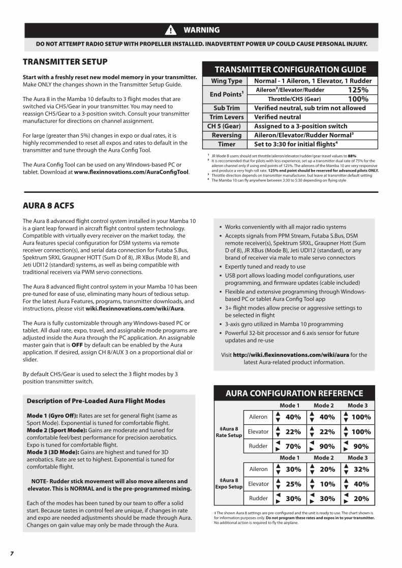
Start with a freshly reset new model memory in your transmitter. Make ONLY the changes shown in the Transmitter Setup Guide.
The Aura 8 in the Mamba 10 defaults to 3 �ight modes that are switched via CH5/Gear in your transmitter. You may need to reassign CH5/Gear to a 3-position switch. Consult your transmitter manufacturer for directions on channel assignment.
For large (greater than 5%) changes in expo or dual rates, it is highly recommended to reset all expos and rates to default in the transmitter and tune through the Aura Con�g Tool.
The Aura Con�g Tool can be used on any Windows-based PC or tablet. Download at www.�exinnovations.com/AuraCon�gTool.
WARNING
DO NOT ATTEMPT RADIO SETUP WITH PROPELLER INSTALLED. INADVERTENT POWER UP COULD CAUSE PERSONAL INJURY.
Description of Pre-Loaded Aura Flight Modes
Mode 1 (Gyro O�): Rates are set for general �ight (same as Sport Mode). Exponential is tuned for comfortable �ight.Mode 2 (Sport Mode): Gains are moderate and tuned for comfortable feel/best performance for precision aerobatics. Expo is tuned for comfortable �ight.Mode 3 (3D Mode): Gains are highest and tuned for 3D aerobatics. Rate are set to highest. Exponential is tuned for comfortable �ight.
NOTE- Rudder stick movement will also move ailerons and elevator. This is NORMAL and is the pre-programmed mixing.
Each of the modes has been tuned by our team to o�er a solid start. Because tastes in control feel are unique, if changes in rate and expo are needed adjustments should be made through Aura. Changes on gain value may only be made through the Aura.
7
End Points1
Sub TrimTrim Levers Veri�ed neutral
CH 5 (Gear)Reversing
Timer
Wing Type
‡ The shown Aura 8 settings are pre-con�gured and the unit is ready to use. The chart shown is for information purposes only. Do not program these rates and expos in to your transmitter. No additional action is required to �y the airplane.
‡Aura 8Rate Setup
‡Aura 8Expo Setup
AURA CONFIGURATION REFERENCE
Aileron 40% 40% 100%
Elevator 22% 22% 100%
Rudder 70% 90% 90%
Aileron
Mode 3Mode 1
30%
Mode 2
20% 32%
Elevator 25% 10% 40%
Rudder 30% 30% 20%
Mode 3Mode 1 Mode 2
TRANSMITTER CONFIGURATION GUIDE
125%Aileron2/Elevator/RudderThrottle/CH5 (Gear) 100%
Veri�ed neutral, sub trim not allowed
Assigned to a 3-position switchAileron/Elevator/Rudder Normal3Set to 3:30 for initial �ights4
Normal - 1 Aileron, 1 Elevator, 1 Rudder
1 JR Mode B users should set throttle/aileron/elevator/rudder/gear travel values to 88% 2 It is reccomended that for pilots with less experience, set up a transmitter dual rate of 75% for the aileron channel only if using end points of 125%. The ailerons of the Mamba 10 are very responsive and produce a very high roll rate. 125% end point should be reserved for advanced pilots ONLY. 3 Throttle direction depends on transmitter manufacturer, but leave at transmitter default setting 4 The Mamba 10 can �y anywhere between 3:30 to 5:30 depending on �ying style
§ Works conveniently with all major radio systems§ Accepts signals from PPM Stream, Futaba S.Bus, DSM remote receiver(s), Spektrum SRXL, Graupner Hott (Sum D of 8), JR XBus (Mode B), Jeti UDI12 (standard), or any brand of receiver via male to male servo connectors§ Expertly tuned and ready to use§ USB port allows loading model con�gurations, user programming, and �rmware updates (cable included)§ Flexible and extensive programming through Windows- based PC or tablet Aura Con�g Tool app§ 3+ �ight modes allow precise or aggressive settings to be selected in �ight§ 3-axis gyro utilized in Mamba 10 programming§ Powerful 32-bit processor and 6 axis sensor for future updates and re-use
Visit http://wiki.�exinnovations.com/wiki/aura for the latest Aura-related product information.
AURA 8 ACFS
The Aura 8 advanced �ight control system installed in your Mamba 10 is a giant leap forward in aircraft �ight control system technology. Compatible with virtually every receiver on the market today, the Aura features special con�guration for DSM systems via remote receiver connection(s), and serial data connection for Futaba S.Bus, Spektrum SRXL Graupner HOTT (Sum D of 8), JR XBus (Mode B), and Jeti UDI12 (standard) systems, as well as being compatible with traditional receivers via PWM servo connections.
The Aura 8 advanced �ight control system in your Mamba 10 has been pre-tuned for ease of use, eliminating many hours of tedious setup. For the latest Aura Features, programs, transmitter downloads, and instructions, please visit wiki.�exinnovations.com/wiki/Aura.
The Aura is fully customizable through any Windows-based PC or tablet. All dual rate, expo, travel, and assignable mode programs are adjusted inside the Aura through the PC application. An assignable master gain that is OFF by default can be enabled by the Aura application. If desired, assign CH 8/AUX 3 on a proportional dial or slider.
By default CH5/Gear is used to select the 3 �ight modes by 3 position transmitter switch.
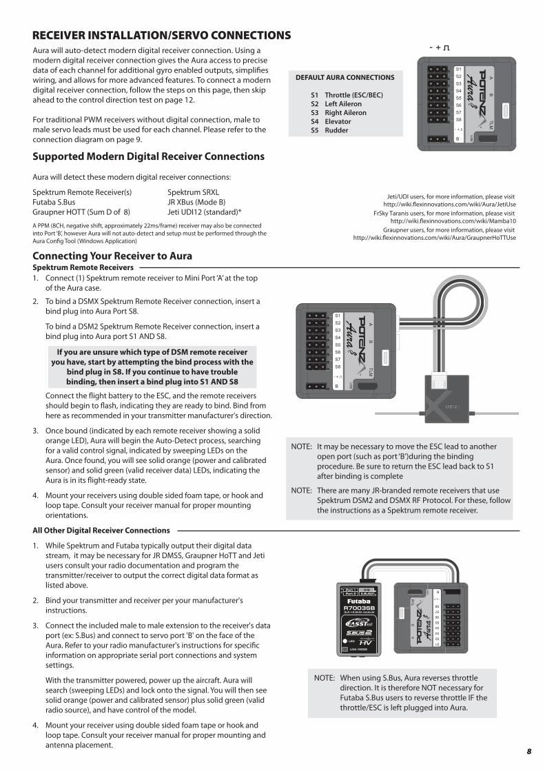
Aura will auto-detect modern digital receiver connection. Using a modern digital receiver connection gives the Aura access to precise data of each channel for additional gyro enabled outputs, simpli�es wiring, and allows for more advanced features. To connect a modern digital receiver connection, follow the steps on this page, then skip ahead to the control direction test on page 12.
For traditional PWM receivers without digital connection, male to male servo leads must be used for each channel. Please refer to the connection diagram on page 9.
DEFAULT AURA CONNECTIONS
S1 Throttle (ESC/BEC) S2 Left Aileron S3 Right Aileron S4 Elevator S5 Rudder
Supported Modern Digital Receiver Connections
Aura will detect these modern digital receiver connections:
Spektrum Remote Receiver(s) Spektrum SRXLFutaba S.Bus JR XBus (Mode B)Graupner HOTT (Sum D of 8) Jeti UDI12 (standard)*
A PPM (8CH, negative shift, approximately 22ms/frame) receiver may also be connected into Port ‘B’, however Aura will not auto-detect and setup must be performed through the Aura Con�g Tool (Windows Application)
Connecting Your Receiver to AuraSpektrum Remote Receivers1. Connect (1) Spektrum remote receiver to Mini Port ‘A’ at the top of the Aura case.
2. To bind a DSMX Spektrum Remote Receiver connection, insert a bind plug into Aura Port S8.
To bind a DSM2 Spektrum Remote Receiver connection, insert a bind plug into Aura port S1 AND S8.
Connect the �ight battery to the ESC, and the remote receivers should begin to �ash, indicating they are ready to bind. Bind from here as recommended in your transmitter manufacturer's direction.
3. Once bound (indicated by each remote receiver showing a solid orange LED), Aura will begin the Auto-Detect process, searching for a valid control signal, indicated by sweeping LEDs on the Aura. Once found, you will see solid orange (power and calibrated sensor) and solid green (valid receiver data) LEDs, indicating the Aura is in its �ight-ready state.
4. Mount your receivers using double sided foam tape, or hook and loop tape. Consult your receiver manual for proper mounting orientations.
All Other Digital Receiver Connections
1. While Spektrum and Futaba typically output their digital data stream, it may be necessary for JR DMSS, Graupner HoTT and Jeti users consult your radio documentation and program the transmitter/receiver to output the correct digital data format as listed above.
2. Bind your transmitter and receiver per your manufacturer's instructions. 3. Connect the included male to male extension to the receiver's data port (ex: S.Bus) and connect to servo port 'B' on the face of the Aura. Refer to your radio manufacturer's instructions for speci�c information on appropriate serial port connections and system settings.
With the transmitter powered, power up the aircraft. Aura will search (sweeping LEDs) and lock onto the signal. You will then see solid orange (power and calibrated sensor) plus solid green (valid radio source), and have control of the model.
4. Mount your receiver using double sided foam tape or hook and loop tape. Consult your receiver manual for proper mounting and antenna placement.
If you are unsure which type of DSM remote receiver you have, start by attempting the bind process with the
bind plug in S8. If you continue to have trouble binding, then insert a bind plug into S1 AND S8
NOTE: There are many JR-branded remote receivers that use Spektrum DSM2 and DSMX RF Protocol. For these, follow the instructions as a Spektrum remote receiver.
NOTE: It may be necessary to move the ESC lead to another open port (such as port ‘B’)during the binding procedure. Be sure to return the ESC lead back to S1 after binding is complete
8
Jeti/UDI users, for more information, please visit http://wiki.�exinnovations.com/wiki/Aura/JetiUse
FrSky Taranis users, for more information, please visit http://wiki.�exinnovations.com/wiki/Mamba10
Graupner users, for more information, please visit http://wiki.�exinnovations.com/wiki/Aura/GraupnerHoTTUse
RECEIVER INSTALLATION/SERVO CONNECTIONS
NOTE: When using S.Bus, Aura reverses throttle direction. It is therefore NOT necessary for Futaba S.Bus users to reverse throttle IF the throttle/ESC is left plugged into Aura.

9
RECEIVER INSTALLATION/SERVO CONNECTIONS (CONTINUED)Connecting a traditional receiver to Aura with PWM Servo Connections
PWM is an acronym which stands for Pulse Width Modulation. A servo will move to a speci�c angle in a speci�c direction based on the width of the signal pulse it receives. Most transmitters output a total pulse width of 1.1-1.9ms, with the midpoint being 1.5ms. Lower pulse widths will move the servo to one side of neutral and higher pulse widths to the other side of neutral. In order to utilize this type of receiver connection with your Mamba 10, male to male servo leads to connect the corresponding receiver ports to Aura are required. A minimum 6-channel receiver is required to setup Aura with PWM connections. Please purchase FPZAU01 Aura 3-piece male to male servo cable/S.Bus to complete the PWM connection setup.
1. Bind your receiver to your transmitter by following the instructions provided by your transmitter and receiver manufacturer. Verify that it is bound by connecting a spare servo to the receiver and verify that it responds to the appropriate input.2. With the transmitter and receiver powered OFF, connect your receiver to Aura using the diagram below. Note that the throttle is plugged directly into the receiver.
3. With the propeller removed and ALL connections made between Aura and the receiver (observing correct polarity), power on your transmitter and the airplane with the �ight battery, ensuring that the airplane is kept stationary. After a few seconds, the LEDs on Aura will sweep back and forth as Aura searches for a valid control signal. Once found, a solid orange (Aura running) and solid green (Aura receiving valid signal from the receiver) LED is illuminated. After the source is found, apply transmitter right rudder to assist Aura determine your radio type, after which point control of the model is established. This is only required during initial setup.
NOTICE
VERIFY PROPER POLARITY OF ALL CABLE CONNECTIONS PRIOR TO ADDING POWER TO THE SYSTEMAll four (4) PWM male-to-male connections must be connected AND connected in the proper polarity from receiver
outputs to Aura inputs for Aura to activate servo outputs. (Aileron - S1, Elevator - S2, Rudder - S3, Gear/CH5 - S4)
CAUTION
Always connect the battery when the throttle stick and throttle trim are in the idle/cut-o� position.
Observe the following procedures to safely power up your model after it has been bound. Ensure propeller is removed unless sequence is followed to power up before �ight.
1. Lower the throttle stick and trim to their lowest setting and turn on the transmitter. Wait for your transmitter to indicate the RF signal is being broadcast before proceeding.
If a battery is connected to the ESC with the throttle fully open on the active transmitter, the ESC will enter into programming mode. If this occurs, simply disconnect the battery, lower the throttle, and reconnect the battery.
2. Ensure the rudder, elevator, and aileron gimbals are centered.3. With the airplane on a solid surface; connect the battery to the ESC and wait. The ESC will emit a series of audible tones during its initialization process. 4. The ESC will emit a short, �nal tone sequence indicating that the ESC is now armed, and that the motor will spin in responose to throttle stick movement.
CONNECTING BATTERY/ARMING ESC
WARNING
When making adjustments to linkages, transmitter settings, or the Aura 8 �ight control system, remove the
propeller to guard against accidental spool up.
WARNING
Hold aircraft securely when connecting the battery before �ight. Always ensure that the propeller is clear of any and all
objects as they may become entangled.
Receiver PWM Inputs
THROTTLEAILERON
ELEVATORRUDDER
GEAR/CH5AUX1/CH6R
X
RUDDER SERVOELEVATOR SERVORIGHT WING AILERON SERVOSLEFT WING AILERON SERVOSESCTo M
otor
To RXServo PWM Outputs
*Note: Arrows indicate signal (data) �ow.They do not necessarily indicate voltage (+) �ow.

MAIN WING INSTALLATION
Required Tools and Fasteners: #1 Phillips Screwdriver, (4) M2x6mm self-tapping Phillips head screws, (1) M3x70mm Phillips machine screws, (8) M3x12mm self-tapping Phillips head screws
1. Locate the (4) cabane struts, fuselage, and top wing. Dry �t the cabane struts into the moulded mounts in the wing and fuselage to ensure proper �tment and alignment. The longer rods are the rear cabane struts, the shorter rods are the front cabane struts.
2. Rotate the cabane to align the screw holes in the cabane and cabane mount and secure to the upper mounts in the top wing with (4) M2x6mm screws. Insert the interplane struts in the lower mounts on the fuselage and mark the depth that each strut inserts into the mount.
3. Remove the wing and wrap low-tack masking tape around the strut on the line marked in Step 2. Using medium (150) grit sandpaper, roughen the lower portion of each cabane strut. Remove tape and clean struts and inside of the fuselage mounts with isopropyl alcohol.
4. Glue cabane struts into the lower mounts on the fuselage with 15-minute epoxy. FULLY SEAT CABANE STRUTS INTO THE LOWER MOUNTS ON THE FUSELAGE AND ENSURE THEY REMAIN SEATED. Clean excess epoxy prior to curing.
5. Once the epoxy has fully cured, unscrew the top wing from the cabane struts and temporarily place it to the side.
6. Locate the bottom wing and the (2) interplane struts.
10

MAIN WING INSTALLATION (CONTINUED)
7. Attach the interplane struts to the bottom wing using (4) M3x12mm Phillips head cap screws. While the struts are directional and will only �t one way, ensure that the logo is oriented outwards and on the bottom side of the strut, oriented upright.
8. Connect the aileron servo leads to either y-harness. Be sure to connect the left wing servo to the lead labeled AIL L, and right wing servo to the lead labeled AIL R, then gently guide them inside the fuselage while mating the bottom wing to the fuselage.
9. Attach the bottom wing to the fuselage with (1) M3x70mm Phillips screws.
10. Re-attach the top wing to the cabanes using the (4) M2x6mm Phillips self-tapping screws removed in Step 5.
11. Attach the top wing to the interplane struts using (4) M3x12mm Phillips self-tapping screws.
11

CONTROL DIRECTION TESTRefer to the chart below to determine the proper control surface directions.
If controls are reversed, DO NOT REVERSE CONTROLS IN TRANSMITTER OR IN THE AURA CONFIG TOOL. Email us at support@�exinnovations.com for corrective action. Note that BOTH the Transmitter Control Direction Test AND the Flight
Controller Sensor Direction Test MUST BOTH BE PASSED! IF ONE DOES NOT PASS, DO NOT FLY!AILER
ON
RUDDER
ELEV
ATO
R
TransmitterCommand
Proper ControlSurface De�ection
Stick Left
Stick Right
Stick Forward
Stick Aft
Stick Left
Stick Right
12
NOTE: There is pre-con�gured rudder to aileron and rudder to elevator mixing programmed into the Aura. Simultaneous movement of these control surfaces with rudder input is intentional and completely NORMAL.
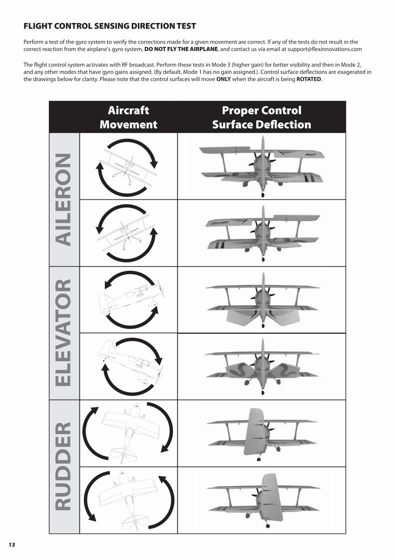
AircraftMovement
Proper ControlSurface De�ection
AILER
ON
RUDDER
ELEV
ATO
R
FLIGHT CONTROL SENSING DIRECTION TEST
Perform a test of the gyro system to verify the corrections made for a given movement are correct. If any of the tests do not result in the correct reaction from the airplane's gyro system, DO NOT FLY THE AIRPLANE, and contact us via email at support@�exinnovations.com
The �ight control system activates with RF broadcast. Perform these tests in Mode 3 (higher gain) for better visibility and then in Mode 2, and any other modes that have gyro gains assigned. (By default, Mode 1 has no gain assigned.). Control surface de�ections are exagerated in the drawings below for clarity. Please note that the control surfaces will move ONLY when the aircraft is being ROTATED.
13

PROPELLER/SPINNER INSTALLATION
Required Tools and Fasteners: #1 Phillips Screwdriver, 13mm Box Wrench, M3x6mm machine screw
1. Insert the prop collet onto the motor shaft. Ensure that it is fully seated.
2. Temporarily remove the prop nut and washer and install the propeller with the convex surface facing forward. The propeller size numbers are printed on the front face of the prop and should orient forward.
3. Slide the prop washer on the collet with the widest face aft, and tighten the prop nut.
NOTICE
Spin the motor over by hand to ensure that the spinner is true after installation.
14
LINKAGE SETUPAdjust the control linkages so that the surfaces are neutral with zero trim and zero subtrim. Adjustments may be required during �ight trimming − for more information, please refer to the trimming section located on page 16 of this manual.
At the servo, the stock linkage attachment is a Z-bend located in the outermost hole in the servo arm for the rudder and elevator, and the center hole for the ailerons.
At the control horn, the stock attachment is a nylon clevis located in the outermost hole for aileron/rudder, and innermost hole for elevator.
SERV
O A
RMS AI
LERO
NS
ELEV
ATO
RRU
DD
ER CON
TRO
L H
ORN
SAI
LERO
NS/
RUD
DER
ELEV
ATO
RNOTICE
The DS15 servos installed in your Mamba 10 are high quality, digital servos with all metal gear train and ultra-�ne gear mesh. This �ne resolution and high tooth count output shaft means that the servo arms pre-installed on the servos may inadvertantly be misaligned, yet appear properly installed. It is critical to ensure the positive, perpendicular orientation of the arm to the case to
ensure that the travel of the servos is even from side to side at extreme throws, particularly on the rudder servo.

15
BATTERY INSTALLATION
1. Push the spring-loaded battery latch tab back to release the battery hatch.
2. Press the battery to the battery tray and secure with the provided hook-and-loop strap. With the recommended battery, the front edge align with the front edge of the battery hatch.
3. Reinstall the hatch, and con�rm that the latch has positively engaged.
CAUTION
Always keep limbs clear from the propeller when the battery is connected. After the ESC arms, the propeller
will rotate when the throttle is moved. Unlike an internal combustion engine, electric motors apply more voltage
to counteract resistance, therefore any object that is entangled in the propeller will be severely damaged
before the motor will stop
WARNING
When making adjustments to linkages, transmitter settings, or the Aura 8 �ight control system, remove the propeller to guard against accidental spool up.
CENTER OF GRAVITY
The location of the center of gravity for the Mamba 10 is located 2 9/16-IN (65MM) AFT of the LEADING EDGE of the BOTTOM WING and is measured by lifting the completed airplane upright, with all components installed, by the bottom wing. This measurement was determined from many test �ights by designer and many time world aerobatic champion, Quique Somenzini. Lift the airplane from the underside of the wing to check the CG.
Setting the center of gravity is one of the most important steps for success, particulary with a new airplane. The Mamba is a high-performance airplane with large control surface throws, and a high thrust to weight ratio. These two factors combined make it a very enjoyable aircraft to �y, but if the center of gravity is not within an acceptable range, it will make the airplane di�cult, if not impossible, to control.
NOTICE
The CG measurement should be made with the completed airframe with all components
(batteries, servos, receiver, linkages, screws, bolts, hardware, etc.) installed. Failure to do
so will result in inaccurate measurement.
2 9/16-IN (65MM)
Selecting a Flying Site
Selecting a �ying site is critical to a successful �ight. Airplanes require a lot more room than other R/C products, therefore, a neighborhood or parking lot is less than ideal. A large open �eld with short grass and generous over�y area are the best candidates if no AMA �eld is available in your area. Know your over�y area - ensure that there are no houses, playgrounds, or other buildings that may be damaged if the airplane were to crash.
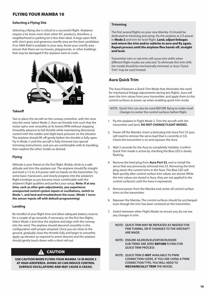
Takeo�
Taxi or place the aircraft on the runway centerline, with the nose into the wind. Select Mode 2, then set throttle trim such that the motor spins over smoothly at its lowest RPM without stopping. Smoothly advance to full throttle while maintaining directional control with the rudder and slight back pressure on the elevator. The airplane should lift o� gently before the throttle is fully open. Fly in Mode 2 until the aircraft is fully trimmed (see special trimming instructions), and you are comfortable with its handling, then explore the other modes as desired.
Flying
Altitude is your friend on the �rst �ight. Briskly climb to a safe altitude and trim the airplane out. The airplane should �y straight and level a 1/2 to 3/4 power with no hands on the transmitter. Try some basic maneuvers, and slowly progress into the airplane’s �ight envelope as you become more comfortable with the airplane’s �ight qualities and perfect your setup. Note: If at any time, such as after gain adjustments, you experience unexpected control system inputs or oscillations, switch to Mode 1, and land and troubleshoot the issue. (Mode 1 turns the sensor inputs o� with default programming)
Landing
Be mindful of your �ight time and allow adequate battery reserve for a couple of go-arounds, if necessary, on the �rst few �ights. Select Mode 2 and slow the airplane and align with the runway, into the wind. The airplane should descend smoothly in this con�guration with proper airspeed. Once you are close to the ground, gradually close the throttle fully and begin to smoothly apply up elevator as required to arrest descent and the airplane should gently touch down with a short roll out.
Aura Quick Trim
The Aura 8 features a Quick Trim Mode that eliminates the needfor mechanical linkage adjustments during test �ights. Aura willlearn the trim values from your transmitter, and apply them to thecontrol surfaces at power up when enabling quick trim mode.
FLYING YOUR MAMBA 10
Trimming
The �rst several �ights on your new Mamba 10 should be dedicated to trimming and setup. Fly the airplane at 2/3 power in Mode 2 and trim for level �ight. Land, adjust linkages and return the trim and/or subtrim to zero and �y again. Repeat process until the airplane �ies hands o�, straight and level.
Transmitter trim or sub-trim will cause trim shifts when di�erent �ight modes are selected. To eliminate this trim shift, the model should be mechanically trimmed, or Aura “Quick Trim” may be used instead.
16
CAUTION
USE CAUTION WHEN FLYING YOUR MAMBA 10 IN MODE 3 AT HIGH AIRSPEEDS. DOING SO CAN INDUCE CONTROL
SURFACE OSCILLATIONS AND MAY CAUSE A CRASH.
NOTE: Quick Trim can also be used BEFORE �ying to make small changes to center the control surfaces before �ight.
1. Fly the airplane in Flight Mode 2. Trim the aircraft with the transmitter and land. DO NOT CHANGE FLIGHT MODES.
2. Power o� the Mamba. Insert a bind plug into Aura Port S3 (you will need to remove the servo lead that is currently in S3). Check the transmitter is on and repower the Aura.
3. Wait 5 seconds for the Aura to completely initialize. Con�rm Quick Trim mode is active by checking the Blue LED is slowly �ashing.
4. Remove the bind plug from Aura Port S3, and re-install the servo that was previously removed into S3. Removing the bind plug stores the current trims in the Aura. The Blue LED will �ash quickly after control surface trim values are stored. While the trim values are stored in Aura, they are not applied to the control surface(s) until the Aura is repowered.
5. Remove power from the Mamba and center all control surface trims on the transmitter.
6. Repower the Mamba. The control surfaces should be unchanged even though the trim has been centered on the transmitter.
7. Switch between other Flight Modes to ensure you do not see any changes in trim.
NOTE: QUICK TRIM MAY BE REPEATED AS NEEDED FOR FINE TUNING, OR IF CHANGES TO THE AIRCRAFT ARE MADE.
NOTE: ENSURE AILERON/ELEVATOR/RUDDER SUB-TRIMS ARE ZERO BEFORE FLYING FOR QUICK TRIM PROCESS
NOTE: QUICK TRIM IS NOT AVAILABLE TO PWM CONNECTION USERS. IF YOU ARE USING A PWM CONNECTION TYPE, YOU WILL NEED TO MECHANICALLY TRIM THE MODEL
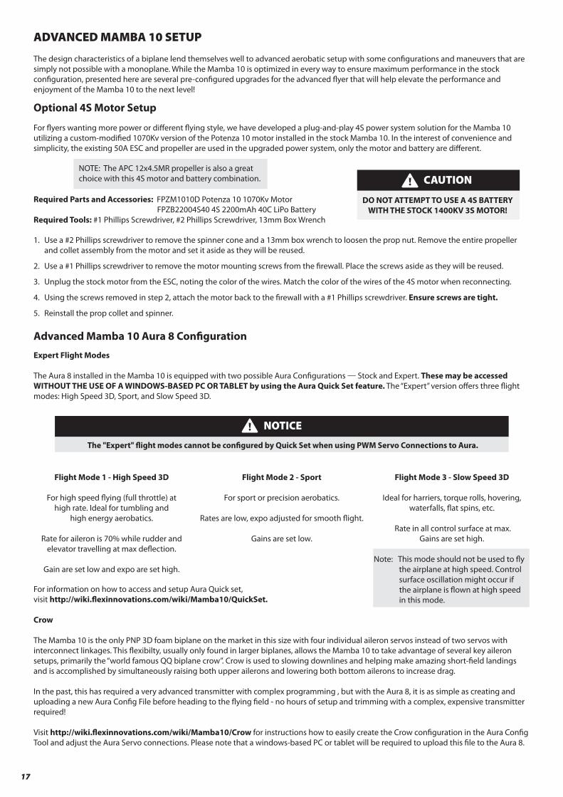
ADVANCED MAMBA 10 SETUP
The design characteristics of a biplane lend themselves well to advanced aerobatic setup with some con�gurations and maneuvers that are simply not possible with a monoplane. While the Mamba 10 is optimized in every way to ensure maximum performance in the stock con�guration, presented here are several pre-con�gured upgrades for the advanced �yer that will help elevate the performance and enjoyment of the Mamba 10 to the next level!
Optional 4S Motor Setup
For �yers wanting more power or di�erent �ying style, we have developed a plug-and-play 4S power system solution for the Mamba 10 utilizing a custom-modi�ed 1070Kv version of the Potenza 10 motor installed in the stock Mamba 10. In the interest of convenience and simplicity, the existing 50A ESC and propeller are used in the upgraded power system, only the motor and battery are di�erent.
Required Parts and Accessories: FPZM1010D Potenza 10 1070Kv Motor FPZB22004S40 4S 2200mAh 40C LiPo BatteryRequired Tools: #1 Phillips Screwdriver, #2 Phillips Screwdriver, 13mm Box Wrench
1. Use a #2 Phillips screwdriver to remove the spinner cone and a 13mm box wrench to loosen the prop nut. Remove the entire propeller and collet assembly from the motor and set it aside as they will be reused.
2. Use a #1 Phillips screwdriver to remove the motor mounting screws from the �rewall. Place the screws aside as they will be reused.
3. Unplug the stock motor from the ESC, noting the color of the wires. Match the color of the wires of the 4S motor when reconnecting.
4. Using the screws removed in step 2, attach the motor back to the �rewall with a #1 Phillips screwdriver. Ensure screws are tight.
5. Reinstall the prop collet and spinner.
Advanced Mamba 10 Aura 8 Con�guration
Expert Flight Modes
The Aura 8 installed in the Mamba 10 is equipped with two possible Aura Con�gurations — Stock and Expert. These may be accessed WITHOUT THE USE OF A WINDOWS-BASED PC OR TABLET by using the Aura Quick Set feature. The “Expert” version o�ers three �ight modes: High Speed 3D, Sport, and Slow Speed 3D.
For information on how to access and setup Aura Quick set, visit http://wiki.�exinnovations.com/wiki/Mamba10/QuickSet.
Crow
The Mamba 10 is the only PNP 3D foam biplane on the market in this size with four individual aileron servos instead of two servos with interconnect linkages. This �exibilty, usually only found in larger biplanes, allows the Mamba 10 to take advantage of several key aileron setups, primarily the “world famous QQ biplane crow”. Crow is used to slowing downlines and helping make amazing short-�eld landings and is accomplished by simultaneously raising both upper ailerons and lowering both bottom ailerons to increase drag.
In the past, this has required a very advanced transmitter with complex programming , but with the Aura 8, it is as simple as creating and uploading a new Aura Con�g File before heading to the �ying �eld - no hours of setup and trimming with a complex, expensive transmitter required!
Visit http://wiki.�exinnovations.com/wiki/Mamba10/Crow for instructions how to easily create the Crow con�guration in the Aura Con�g Tool and adjust the Aura Servo connections. Please note that a windows-based PC or tablet will be required to upload this �le to the Aura 8.
17
Flight Mode 1 - High Speed 3D
For high speed �ying (full throttle) at high rate. Ideal for tumbling and
high energy aerobatics.
Rate for aileron is 70% while rudder and elevator travelling at max de�ection.
Gain are set low and expo are set high.
Flight Mode 3 - Slow Speed 3D
Ideal for harriers, torque rolls, hovering, waterfalls, �at spins, etc.
Rate in all control surface at max. Gains are set high.
Note: This mode should not be used to �y the airplane at high speed. Control
surface oscillation might occur if the airplane is �own at high speed in this mode.
Flight Mode 2 - Sport
For sport or precision aerobatics.
Rates are low, expo adjusted for smooth �ight.
Gains are set low.
NOTICE
The "Expert" �ight modes cannot be con�gured by Quick Set when using PWM Servo Connections to Aura.
NOTE: The APC 12x4.5MR propeller is also a great choice with this 4S motor and battery combination. CAUTION
DO NOT ATTEMPT TO USE A 4S BATTERY WITH THE STOCK 1400KV 3S MOTOR!

AIRFRAME REPAIRS
The Mamba 10 is molded from durable EPO foam and is repairable with most adhesives. Similar to building and repairing wood or compos-ite airplanes, the correct glue for a given application is critical to the repair holding and not breaking again. For major repairs, such as a broken fuselage, epoxy is preferred because it allows time to correct any misalignment. For smaller repairs, such as a cracked control surface or small chunk of material missing from the airframe, regular CA is very e�ective. The use of odorless (foam safe) CA is not recommended on EPO foam aircraft because it is weaker than regular CA and takes a longer period of time to cure and the bond tends to be weaker.
If a part is damaged too badly to be repaired, please refer to the front of the manual for a complete listing of spare airframe parts.
NOTE: Avoid the use of CA accelerant in repairs. It can damage paint and will weaken the bond of the glue. If CA accelerant is used, be mindful of the locations of CA to prevent premature bonding of parts, or bonding a hand or clamp to the airframe.
REPLACING AILERON SERVOS
Required Tools and Fasteners: #1 Phillips Screwdriver, #11 or single-edged razor blade 1. Unplug the servo from the receiver.
2. Unscrew the servo arm from the servo and remove the servo arm.
3. Using a sharp blade, carefully cut the tape around the perimeter of the servo. DO NOT CUT THE SERVO LEAD.
4. Unscrew the two mounting screws located at each end of the servo and remove.
NOTICE: If a crash is imminent, fully reduce the throttle to prevent further damage to the power system and reduce energy to lessen impact damage. Never allow the propeller to contact the ground under power, even idle.
BE ADVISED THAT CRASH DAMAGE IS NOT COVERED UNDER ANY PRODUCT WARRANTY.
Avoid keeping the airplane in direct sunlight when not �ying. Excessive heat can damage the airplane’s structure and UV damage can permanently discolor decals.
18
TIP: Plug a spare extension lead into the servo when removing to make it easier to install the lead of the servo when replaced.

SERVICING THE POWER SYSTEM
Required Tools and Fasteners: #1 Phillips Screwdriver, 13mm box wrench 1. Remove the propeller and spinner assembly from the motor.
2. Remove the (4) bolts holding the motor to the �rewall using a #1 Phillips screwdriver. Disconnect the motor from the ESC.
3. To remove the ESC, simply unplug its lead from the receiver or Aura and the output leads from the motor.
OPTIONAL WHEEL PANT REMOVAL
For �yers that want the lightest possible setup, or that �y o� of rough/unimproved �elds, the wheelpants on the Mamba 10 are designed to be removable. Two wheel collars have been provided in the hardware bag to retain the wheels after the wheelpants are removed.
Required Tools and Fasteners: #1 Phillips Screwdriver, 1.5mm hex driver, (2) wheel collars
1. Invert the airplane and locate the two wheelpant retaining screws and remove them. Slide the wheelpants and tires o� of the axles.
2. Remove the wheel from the wheelpant and reinstall on the axle.
3. Slide the wheel collar onto the axle with the shoulder (o�set) side towards the wheel. Tighten the set screw on the wheel collar.
TIP: reinstall the wheelpant retaining collar and screws to prevent losing parts in case you wish to reinstall them.
TIP: use blue threadlocker on the wheel collar set screw for added security.
19

AIRCRAFT TROUBLESHOOTING GUIDE
Should you encounter any abnormal situations with your Mamba 10, refer to the matrix below to determine the probable cause and a recommended solution for the action.
If the required solution does not rectify the problem, please contact product support for further assistance.
NOTICE
Unless speci�cally required, ALWAYS troubleshoot the airplane with the propeller removed.
20
Trims are not properly zeroed
Ensure battery packs are adequately warm (70°F/21°C) before �ight
Install propeller so that the convex side faces forward (tractor con�guration)
DISCREPANCY PROBABLE CAUSE RECOMMENDED SOLUTION
Motor nonresponsive (ESCintialization tones audible)
Throttle not at idle and/or throttle trim too highLower throttle stick and trim completely. If problem persists, ensure that the sub-trim and travel adjust are properly set in the radio’s programming.
Throttle channel is reversed Reverse throttle channel in radio programmingMotor nonresponsive (no ESCinitialization tones audible) Motor disconnected from ESC
Ensure plugs are fully seated. Check battery and/or plugs for damage and replaceany damaged components found - DO NOT ATTEMPT REPAIR
Motor turns in the wrongdirection
The three motor wires are connected incorrectlyto the ESC Swap any TWO motor wires.
Ensure battery is fully charged prior to installing in aircraftPropeller installed backwardsFlight battery damagedAmbient temperature is too cold Battery capacity too small for intended use Replace battery with one of proper capacity and discharge capacity (C rating)
Battery is too weak or damaged Check battery’s physical condition, check battery voltages after chargeBattery’s discharge rating may be too small Replace battery with one with higher ‘C’ rating
Excessive propeller noise and/or vibration
Damaged spinner and/or propeller, collet, or motor Replace damaged components - DO NOT ATTEMPT REPAIRPropeller is not balanced Balance or replace the propellerProp nut is loose Tighten prop nut with appropriate-sized wrenchSpinner is not fully in place or tightened Loosen the spinner bolt, adjust as required, retighten spinner bolt
Control surfacesnonresponsive
Airframe or control linkage system damageExamine airframe for damage, repair as required; inspect control linkage system(servo, pushrod, control horn) for damaged components and replace as required
Wire damaged or connector loose Examine wires and conntections, replace as neccesaryTransmitter bound incorrectly, incorrect activemodel memory, incorrect Aura data input con�guration, incorrect Aura transmitter settings
Consult radio manual for proper binding and model selection instructions
Battery voltage too low Use volt meter to check battery; recharge or replace as necessaryBattery disconnected from ESC Check that the EC3 plugs are fully seatedBEC (battery elimination circuit) damaged Replace ESC - DO NOT ATTEMPT REPAIR
Controls reversed Aura 8 or transmitter settings incorrectRefer to control surface direction chart and transmitter setup; adjust appropriatesettings as required. Check Mamba 10 and Aura wiki web pages for additionalinformation. Contact customer support at support@�exinnovations.com
Control surface oscillation
Reduce airspeed
Propeller/spinner not balanced Balance or replace propeller and/or spinnerMotor vibration Inspect motor mounting bolts and re-tighten as necessaryLoose Aura 8 mounting Re-align and secure the Aura 8 to the aircraftControl linkage slop Examine control system and repair or replace work componentsImproper transmitter setup
Trim changes between�ight modes
Trims are not properly zeroed Readjust control linkage and re-center trims in radioSub-trim is not properly zeroed Remove sub-trim; adjust the servo arm or clevis to achieve proper geometry
Damaged propeller or spinner Replace damaged component- DO NOT ATTEMPT REPAIR
Refer to Aura 8 manual to decrease desired control surface gain
Propeller nut or propeller adapter threads notcut straight Replace propeller nut or propeller shaft - DO NOT ATTEMPT REPAIR
Damaged Servo Replace Servo - DO NOT ATTEMPT REPAIR
Failed control direction test Incorrect Aura 8 or Transmitter Setting -DO NOT FLY!
Reference transmitter and receiver sections of this manual. If no solution found,contact customer support at support@�exinnovations.com
Improperly set master gain Ensure master gain is set for proper gain value
Reduced �ight time or aircraft underpowered
Remove battery from service completely and replace with a di�erent battery
ESC reaching preset LVC (low-voltage cuto�) Recharge �ight battery or reduce �ight time
Exceeding maximum airspeed for con�gurationGains too high for aircraft/�ight con�guration
Refer to Aura 8 manual to correctly con�gure transmitter
Transmitter is not properly calibrated (aileron/elevator/rudder are not neutral with stickscentered; reference transmitter monitor
Calibrate transmitter (reference manufacturer’s instructions, or return to manufacturer for calibration
Any of four PWM servo cables are not connected Connect all four male to male servo cables between your receiver and AuraPWM servo cables connected to incorrect ports Reconnect cables to proper ports. Reference chart on page XXPolarity of PWM servo cables not correctReceiver not bound and/or outputting PWMservo pulses
Bind receiver per manufacturer instructions and verify with a servo to ensure PWM signal is output from each channel as required.
PWM connection type andcannot get orange+greenAura and control of model
Reconnect servo cables with proper polarity. Reference chart on page XX
COMPLIANCE INFORMATION FOR THE EUROPEAN UNION Declaration of Conformity (In accordance with ISO/IEC 17050-1)
Product(s): Mamba 10 Super PNPItem Number(s): FPR3270A/FPR3270B
The object of declaration described above is in conformity with the requirements of the speci�cations listed below, following the provisions of the EMC Directive 2004/108/EC.
EN 55022: 2010+AC: 2011EN 55024: 2010EN 61000-3-2: 2006+A2:2009EN 61000-3-3: 2013
EN 61000-6-3: 2007/A1:2011EN 61000-6-1: 2007
LIMITED WARRANTYWarranty Coverage
Flex Innovations, Inc. and its authorized resellers (“Flex”) warrant to the original purchaser that the product purchased (the “Product”) it will be free from defects in materials and workmanship at the date of purchase. Outside of Coverage
This warranty is not transferable and does not cover:
(a) Products with more than 45 days after purchased date. (b) Damage due to acts of God, accident, misuse, abuse, negligence, commercial use, or due to improper use, installation, operation or maintenance (c) Modi�cation of or to any part of the Product. (d) Product not compliant with applicable technical regulations. (e) Shipping damage. (f ) Cosmetic damage
OTHER THAN THE EXPRESS WARRANTY ABOVE, FLEX MAKES NO OTHER WARRANTY OR REPRESENTATION, AND HEREBY DISCLAIMS ANY AND ALL IMPLIED WARRANTIES, INCLUDING, WITHOUT LIMITATION, THE IMPLIED WARRANTIES OF NONINFRINGEMENT, MERCHANTABILITY AND FITNESS FOR A PARTICULAR PURPOSE. THE PURCHASER ACKNOWLEDGES THAT THEY ALONE HAVE DETER-MINED THAT THE PRODUCT WILL SUITABLY MEET THE REQUIRE-MENTS OF THE PURCHASER’S INTENDED USE.
Purchaser’s Solution
Flex’s sole obligation and purchaser’s sole and exclusive remedy shall be that Flex will, at its option, either (i) service, or (ii) replace, any Product determined by Flex to be defective. Flex reserves the right to inspect any and all Product(s) involved in a warranty claim. Service or replacement decisions are at the sole discretion of Flex. Proof of purchase is required for all warranty claims. SERVICE OR REPLACEMENT AS PROVIDED UNDER THIS WARRANTY IS THE PURCHASER’S SOLE AND EXCLUSIVE REMEDY.
Limitation of Liability
FLEX SHALL NOT BE LIABLE FOR SPECIAL, INDIRECT, INCIDENTAL OR CONSEQUENTIAL DAMAGES, LOSS OF PROFITS OR PRODUCTION OR COMMERCIAL LOSS IN ANY WAY, REGARDLESS OF WHETHER SUCH CLAIM IS BASED IN CONTRACT, WARRANTY, TORT, NEGLIGENCE, STRICT LIABILITY OR ANY OTHER THEORY OF LIABILITY, EVEN IF FLEX HAS BEEN ADVISED OF THE POSSIBILITY OF SUCH DAMAGES.
Further, in no event shall the liability of Flex exceed the individual price of the Product on which liability is asserted. As Flex has no control over use, setup, assembly, modi�cation or misuse, no liability shall be assumed nor accepted for any resulting damage or injury. By the act of use, setup or assembly, the user accepts all resulting liability. If you as the purchaser or user are not prepared to accept the liability associated with the use of the Product, purchas-er is advised to return the Product immediately in new and unused condition to the place of purchase.
Law
These terms are governed by Florida law (without regard to con�ict of law principals). This warranty gives you speci�c legal rights, and you may also have other rights which vary from state to state. FLEX RESERVES THE RIGHT TO MODIFY THIS WARRANTY AT ANY TIME WITHOUT PRIOR NOTICE.
Questions & Assistance
Visit http://www.�exinnovations.com/�ex-authorized-reseller for customer support in your region.
Inspection or Services
If this Product needs to be inspected or serviced and is compliant in the region you live and use the Product in, please contact your regional Flex authorized reseller. Pack the Product securely using a shipping carton. Please note that original boxes needs to be included, but are not designed to withstand the rigors of shipping without additional protection. Ship via a carrier that provides tracking and insurance for lost or damaged parcels, as Flex is not responsible for merchandise until it arrives and is accepted at our facility.
Warranty Requirements
For Warranty consideration, you must include your original sales receipt verifying the proof of purchase date. Provided warranty conditions have been met, your Product will be replaced free of charge. Shipping charges are as follow: to Flex by customer, Flex out it is by Flex. Service or replacement decisions are at the sole discretion of Flex.
Instructions for disposal of WEEE by users in the European Union
This product must not be disposed of with other waste. Instead, it is the user’s responsibility to dispose of their waste equipment by handing it over to a designated collections point for the recycling of waste and electronic equipment. The sepearate collection and recycling of your waste equipment at the time of disposal will help to conserve natural resources and ensure that it is recycled in a manner that protects human health and the environment. For more information about where to drop o� your waste equipment for recycling, please contact your local city o�ce, your household waste disposal service or where you purchased the product.
21
Academy of Model Aeronautics National Model Aircraft Safety CodeE�ective January 1, 2014
A. GENERAL: A model aircraft is a non-human-carrying aircraft capable of sustained �ight in the atmosphere. It may not exceed limitations of this code and is intended exclusively for sport, recreation, education and/or competition. All model �ights must be conducted in accordance with this safety code and any additional rules speci�c to the �ying site. 1. Model aircraft will not be �own: (a) In a careless or reckless manner. (b) At a location where model aircraft activities are prohibited. 2. Model aircraft pilots will: (a) Yield the right of way to all human-carrying aircraft. (b) See and avoid all aircraft and a spotter must be used when appropriate. (AMA Document #540-D.) (c) Not �y higher than approximately 400 feet above ground level within three (3) miles of an airport without notifying the airport operator. (d) Not interfere with operations and tra�c patterns at any airport, heliport or seaplane base except where there is a mixed use agreement. (e) Not exceed a takeo� weight, including fuel, of 55 pounds unless in compliance with the AMA Large Model Airplane program. (AMA Document 520-A.) (f ) Ensure the aircraft is identi�ed with the name and address or AMA number of the owner on the inside or a�xed to the outside of the model aircraft. (This does not apply to model aircraft �own indoors.) (g) Not operate aircraft with metal-blade propellers or with gaseous boosts except for helicopters operated under the provisions of AMA Document #555. (h) Not operate model aircraft while under the in�uence of alcohol or while using any drug that could adversely a�ect the pilot’s ability to safely control the model. (i) Not operate model aircraft carrying pyrotechnic devices that explode or burn, or any device which propels a projectile or drops any object that creates hazard to persons or property. Exceptions: § Free Flight fuses or devices that burn producing smoke and are securely attached to the model aircraft during �ight. § Rocket motors (using solid propellant) up to a G-series size may be used provided they remain attached to the model during �ight. Model rockets may be �own in accordance with the National Model Rocketry Safety Code but may not be launched from model aircraft. § O�cially designated AMA Air Show Teams (AST) are authorized to use devices and practices as de�ned within the Team AMA Program Document. (AMA Document #718.) (j) Not operate a turbine-powered aircraft, unless in compliance with the AMA turbine regulations. (AMA Document #510-A.) 3. Model aircraft will not be �own in AMA sanctioned events, air shows or model demonstrations unless: (a) The aircraft, control system and pilot skills have successfully demonstrated all maneuvers intended or anticipated prior to the speci�c event. (b) An inexperienced pilot is assisted by an experienced pilot. 4. When and where required by rule, helmets must be properly worn and fastened. They must be OSHA, DOT, ANSI, SNELL or NOCSAE approved or comply with comparable standards.
B. RADIO CONTROL (RC) 1. All pilots shall avoid �ying directly over unprotected people, vessels, vehicles or structures and shall avoid endangerment of life and property of others. 2. A successful radio equipment ground-range check in accordance with manufacturer’s recommendations will be completed before the �rst �ight of a new or repaired model aircraft. 3. At all �ying sites a safety line(s) must be established in front of which all �ying takes place. (AMA Document #706.) (a) Only personnel associated with �ying the model aircraft are allowed at or in front of the safety line. (b) At air shows or demonstrations, a straight safety line must be established. (c) An area away from the safety line must be maintained for spectators. (d) Intentional �ying behind the safety line is prohibited.
4. RC model aircraft must use the radio-control frequencies currently allowed by the Federal Communications Commission (FCC). Only individuals properly licensed by the FCC are authorized to operate equipment on Amateur Band frequencies. 5. RC model aircraft will not knowingly operate within three (3) miles of any pre-existing �ying site without a frequency-management agreement. (AMA Documents #922 and #923.) 6. With the exception of events �own under o�cial AMA Competition Regulations, excluding takeo� and landing, no powered model may be �own outdoors closer than 25 feet to any individual, except for the pilot and the pilot's helper(s) located at the �ightline. 7. Under no circumstances may a pilot or other person touch an outdoor model aircraft in �ight while it is still under power, except to divert it from striking an individual. 8. RC night �ying requires a lighting system providing the pilot with a clear view of the model’s attitude and orientation at all times. Hand- held illumination systems are inadequate for night �ying operations. 9. The pilot of an RC model aircraft shall: (a) Maintain control during the entire �ight, maintaining visual contact without enhancement other than by corrective lenses prescribed for the pilot. (b) Fly using the assistance of a camera or First-Person View (FPV) only in accordance with the procedures outlined in AMA Document #550. (c) Fly using the assistance of autopilot or stabilization system only in accordance with the procedures outlined in AMA Document #560.
C. FREE FLIGHT 1. Must be at least 100 feet downwind of spectators and automobile parking when the model aircraft is launched. 2. Launch area must be clear of all individuals except mechanics, o�cials, and other �iers. 3. An e�ective device will be used to extinguish any fuse on the model aircraft after the fuse has completed its function.
D. CONTROL LINE 1. The complete control system (including the safety thong where applicable) must have an inspection and pull test prior to �ying. 2. The pull test will be in accordance with the current Competition Regulations for the applicable model aircraft category. 3. Model aircraft not �tting a speci�c category shall use those pull-test requirements as indicated for Control Line Precision Aerobatics. 4. The �ying area must be clear of all utility wires or poles and a model aircraft will not be �own closer than 50 feet to any above-ground electric utility lines. 5. The �ying area must be clear of all nonessential participants and spectators before the engine is started.
If you are not an AMA member, please consider joining. Founded in 1936 and open to anyone interested in model aviation, the AMA is the governing body for model aviation in the United States and sanctions over 2,000 competitions annually. Membership in the AMA provides liability insurance coverage, protects modelers’
rights and interests, and is required to �y at most of the 2,700+ R/C sites nationwide.
Academy of Model Aeronautics5161 East Memorial Drive
Muncie, IN 47302-9252Toll Free (800) 435-9262
Fax (765) 741-0057
www.modelaircraft.org
22

© 2017 Flex Innovations, Inc.Premier Aircraft™, Potenza™, and Top Value RC™ are trademarks or registered trademarks of Flex Innovations, Inc.
DSM®, DSM2™, and DSMX™ are trademarks of Horizon Hobby, Inc. Futaba is a registered trademark of Futaba Denshi Kogyo Kabushiki Kaisha Corporation of Japan.
Jeti, UDI, and Jeti Model are trademarks or registered trademarks of Jelen, Ing. Stanislav of Czech RepublicHoTT is a registered trademark of SJ, Inc.
Rev.ACreated 02/2017
w w w.f lexinnovations.com
O�cially Licensed Product