fracture-flow-enhanced matrix diffusion in solute
TRANSCRIPT

Transp Porous Med (2010) 81:21–34DOI 10.1007/s11242-009-9383-4
Fracture-Flow-Enhanced Matrix Diffusion in SoluteTransport Through Fractured Porous Media
Yu-Shu Wu · Ming Ye · E. A. Sudicky
Received: 23 August 2007 / Accepted: 17 March 2009 / Published online: 1 April 2009© Springer Science+Business Media B.V. 2009
Abstract Over the past fewdecades, significant progress of assessing chemical transport infractured rocks has been made in laboratory and field investigations as well as in mathematicmodeling. In most of these studies, however, matrix diffusion on fracture–matrix surfaces isconsidered as a process of molecular diffusion only. Mathematical modeling based on thistraditional concept often had problems in explaining or predicting tracer transport in fracturedrock. In this article, we propose a new conceptual model of fracture-flow-enhanced matrixdiffusion, which correlates with fracture-flow velocity. The proposed model incorporates anadditional matrix-diffusion process, induced by rapid fluid flow along fractures. Accordingto the boundary-layer theory, fracture-flow-enhanced matrix diffusion may dominate mass-transfer processes at fracture–matrix interfaces, where rapid flow occurs through fractures.The new conceptual model can be easily integratedwith analytical solutions, as demonstratedin this article, and numerical models, as we foresee. The new conceptual model is prelim-inarily validated using laboratory experimental results from a series of tracer breakthroughtests with different velocities in a simple fracture system. Validating of the new model withfield experiments in complicated fracture systems and numerical modeling will be exploredin future research.
Keywords Matrix diffusion · Solute transport · Contaminant transport · Tracer test ·Fractured porous media
Y.-S. Wu (B)Colorado School of Mines, Golden, CO, USAe-mail: [email protected]
M. YeFlorida State University, Tallahassee, FL, USA
E. A. SudickyUniversity of Waterloo, Waterloo, ON, Canada
123

22 Y.-S. Wu et al.
List of Symbolsb Half aperture of fractures (m)c Concentration (kg/m3)c, ci Simulated concentration (kg/m3)c∗ Measured concentration (kg/m3)cf (Averaged) solute concentration across fractures (kg/m3)cm Solute concentration of the matrix on the matrix block surface (kg/m3)co Constant fracture source solute concentration (kg/m3)D Hydrodynamic dispersion coefficient along fractures (m2/s)DE Effective enhanced matrix-diffusion coefficient (m2/s)Dm Free-solution molecular diffusion coefficient (m2/s)D∗ Effective molecular diffusion coefficient (m2/s)hc Mass-transfer coefficient at the fracture–matrix interface (m/s)Kf Distribution coefficient (m) on fracture surfaces, defined the solute mass adsorbed
per unit area of fracture surface divided by solute concentration in solutionn Exponentialp Laplace operatorRf Fracture-face retardation coefficientqc Mass-transfer flux at the fracture and matrix interface [kg/(sm2)]v Mean-flow velocity in fracture (m/s)�v Fracture-flow velocity vector (m/s)wi Weighting factorαE Fracture-flow-enhanced dispersivity (m2−n /s1−n)δc Thickness of a concentration boundary (film) layer (m)δh Velocity boundary-layer thickness (m)φ Porosity of the matrix� Objective function of Eq. 10λ Decay constant (1/s)τ Tortuosity of matrix porous media
1 Introduction
Earlier studies of flow and transport in fractured porous media were motivated primarilyby concerns related to petroleum and geothermal energy technologies, as well as interest ingroundwater resources from fractured reservoirs (e.g., Warren and Root 1963). In the 1970sand 1980s, chemical or solute transport through fractured porous media received increasingattention from investigators involved in underground natural-resource recovery, as well as insubsurface contamination and remediation. Since then, fractured rock has been recognized toplay an important role in the transport of natural resources or contaminants through subsur-face systems. Over the past few decades, significant progress has beenmade in understandingandmodeling transport phenomena in fractured porousmedia (e.g., Tang et al. 1981; Sudickyand Frind 1982; Rasmuson et al. 1982; Huyakorn et al. 1983; Pruess and Narasimhan 1985;Berkowitz 2002).
In recent years, interest has grown in investigating solute transport through fractured rock,driven by environmental concerns related to radionuclide transport in fractured formations(e.g., Liu et al. 2003, 2004a; Hu et al. 2004; Reimus and Callahan 2007). Moreover, suit-ability evaluations for underground geological storage of high-level radioactive waste in
123

Fracture-Flow-Enhanced Matrix Diffusion in Solute Transport 23
fractured rock have generated renewed interest in investigations of tracer and radionuclidetransport in a fractured geological system. In addition, application of tracer tests, includ-ing environmental tracers and man-made gas- and liquid-tracer injection, has become astandard technique in characterizing fractured rock formations. All these investigations andexperiments require an in-depth, quantitative understanding of fracture–matrix diffusion andinteraction.
Since the 1970s, while understanding fracture–matrix interaction has been the focus ofinvestigation into flow and transport processes in fractured rock, matrix diffusion has beengradually recognized as one of the most important mechanisms that control radionuclidetransport processes in fractured rock (e.g., Neretnieks 1980; Neretnieks et al. 1982; Mal-oszewski and Zuber 1993; Liu et al. 2004a). Even in the laboratory, fracture–matrix diffusionis also found to be dominant (Neretnieks et al. 1982; Sudicky et al. 1985; Wu and Pruess2000). However, field tracer tests (e.g., Liu et al. 2003, 2004a) have shown that fracture–matrix interaction through matrix diffusion may be too large (or “enhanced”) to be explainedby traditional advection–diffusion theory. In order to match tracer experimental results froma large-scale field test, Liu et al. (2003) had to increase fracture–matrix interfacial areas bya factor of 2–4, or to significantly increase effective matrix diffusion. Several studies havebeen carried out to look into why such enhanced matrix diffusion occurs at fracture–matrixinterfaces, with mechanisms ranging from scale dependency of the effective matrix-diffusioncoefficient (Liu et al. 2004b) to possible effects of small-scale fractures or large fracture–matrix interaction areas (Wu et al. 2004).
Even with the significant progress made in laboratory and field investigations, as wellas in mathematical modeling, matrix diffusion on fracture–matrix surfaces has been exclu-sively considered as a molecular diffusion process only. As a result, mathematical mod-eling approaches based on this traditional concept have had difficulty in matching orexplaining laboratory and field testing results (e.g., Neretnieks et al. 1982; Starr et al. 1985;Maloszewski and Zuber 1993; Liu et al. 2003, 2004a). Here, we propose an additional matrix-diffusion mechanism: matrix-diffusion enhancement induced by rapid fluid flow withinfractures. According to the boundary-layer or film theory (e.g., Bird et al. 1960; Fahien1983), fracture-flow-enhanced matrix diffusion may dominate mass-transfer processes atfracture–matrix interfaces, because rapid flow along fractures results in high velocity orlarge concentration gradients at and near fracture–matrix interfaces, enhancing matrix dif-fusion on matrix surfaces. In this article, we present a new formulation of the conceptualmodel for such enhanced fracture–matrix diffusion, and its implementation is discussedusing existing analytical solutions and numerical models. The new model can be easily inte-grated with existing analytical solutions, as demonstrated in this article; we foresee thatintegrating the model with numerical model is not difficult. In addition, we use the enhancedmatrix diffusion concept to analyze laboratory experimental results from nonreactive andreactive tracer breakthrough tests, in an effort of preliminary validation of the new concep-tual model. The model is considered validated by the experiment results of a simple fracturesystem, because the experiment results with different velocities are explained reasonablywell by the model using a consistent set of parameters. If the fracture-flow-enhanced matrixdiffusion is ignored as in Starr et al. (1985), the model parameters must be adjusted fordifferent velocities to obtain the same level of fitting to the experimental results. Furthervalidating the new conceptual model using field experiment in complicated fracture sys-tem (e.g., fractured network) and using numerical models will be conducted in the futureresearch.
123

24 Y.-S. Wu et al.
2 Physical Consideration and Conceptual Model
The schematic of vertical fracture–matrix systems under study is shown in Fig. 1. A fractureis subject to fluid flow with an averaged velocity of v, in which a boundary layer of lami-nar flow may be created (Fig. 1a) or the flow becomes fully developed within the fracture(Fig. 1b). For simplicity, it is assumed that fluid flow occurs only within fractures, the matrixis impermeable, and mass transfer across fracture–matrix interfaces and within the matrixis by diffusion only. As shown in Fig. 1a, a concentration profile, c(x), with a concentrationboundary (film) layer develops along the vertical fracture–matrix interface at depth. Accord-ing to the boundary-layer or film theory (e.g., Fahien 1983), the mass transfer (qc) of soluteper unit area at the fracture and matrix interface is given by
qc = hc(cf − cm) ≈ Dm(cf − cm)
δc, (1)
where hc is the mass-transfer coefficient at the fracture–matrix interface; cf is the (averaged)solute concentration across fractures; cm is the solute concentration of the matrix on thematrix block surface; and δc is the thickness of a concentrated boundary (film) layer for masstransfer (Fig. 1a). Equation 1 indicates that the mass-transfer coefficient hc (similar to theheat-transfer coefficient in advective heat transfer) is determined by the free-solution molec-ular diffusion coefficient, Dm, of the matrix, divided by the effective concentration-layer(film) thickness (Fig. 1a) δc
hc ≈ Dm
δc. (2)
Note that the concentration boundary-layer thickness δc is related to the velocity bound-ary-layer thickness (δh, Fig. 1a), in general, while the latter in turn depends on fracture-flowvelocity or Reynolds number, among other variables.
As shown in Fig. 1a, once boundary layers develop in fractures, the classic boundary-layertheory provides a physical base for fracture-flow-enhanced matrix diffusion (e.g., Bird et al.1960); the larger the fracture-flow velocity (or the Reynolds number), the thinner the velocityor concentration boundary layers. Then, the mass-transfer coefficient of (2) becomes larger,leading to larger mass-transfer flux (Eq. 1). In addition, plug or turbulent flow, if it occurswithin fractures, could be considered as a special case of the boundary-layer concept, i.e., atplug or turbulent flow, the thickness of the flow boundary “layer” as well as the concentrationboundary layer (δc) is tiny or infinitesimal. This is because along the matrix solid surface,the velocity is zero, and plug or turbulent flow will create huge velocity and concentrationgradients perpendicular to matrix surfaces, which will be compensated by enhanced matrixdiffusion into matrix blocks.
In general, fracture apertures in geological formations are very small, normally rangingfrom micrometers to millimeters, and velocity and/or concentration profiles may becomefully developed in fractures (Fig. 1b). In such a case, Eq. 1 may be replaced by the followingexpression:
qc = hc[c(x = 0)cm] ≈ Dm[c(x = 0) − cm]b
, (3)
where c(x = 0) is the concentration at the center of a fracture (x being perpendicular to frac-tures, Fig. 1b) and b is the half aperture of fractures (See Fig. 1). In this case, themass-transfercoefficient may be approximated as
123

Fracture-Flow-Enhanced Matrix Diffusion in Solute Transport 25
Fig. 1 Fracture–matrix system illustrating concentration and velocity profiles within a fracture, as well asa concentration boundary or film layer at the fracture–matrix interface: a velocity boundary layer (thick-ness= δh), and concentration boundary (film) layer (thickness= δc) with a large fracture; b fully developedflow velocity and concentration profiles (δc = b) with a small fracture
hc ≈ Dm
b. (4)
Note that the mass-transfer coefficient at fracture–matrix interfaces, as defined by Eq. 4,becomes constant. However, the concentration at the center of fractures, c(x = 0), wouldincrease with large fracture-flow velocity under fully developed flow conditions, becauseadvective transport is the strongest along the center stream line of fractures (Fig. 1b), leadingto increase in concentration gradients or enhanced diffusion into the matrix, as implicitlydescribed by Eq. 3.
Mass flux continuity at the fracture–matrix interface requires that the mass-transfer rateof (1) or (3) be balanced by actual mass diffused into the matrix. The same amount of massflux may be described by the following effective enhanced matrix diffusion term:
qc = −DE∂c∂x
∣∣∣∣x=b
. (5)
Here, we introduce an effective enhanced matrix-diffusion coefficient DE to include theenhancedmass-transfer effect,which is induced by fast fracture flow. Specifically,we proposethe following expression for calculating the effective enhanced matrix-diffusion coefficientas
DE = φ(
D∗ + αEvn)
, (6)
where the effective molecular diffusion coefficient is D∗ = τDm (τ being the tortuosity ofthe matrix porous medium) and φ is porosity of the matrix. In Eq. 6, we introduce the twonew parameters, i.e., a constant coefficient αE and an nonnegative exponential n. In analogy
123

26 Y.-S. Wu et al.
with hydrodynamic dispersion methodology, αE is called the fracture-flow-enhanced disper-sivity (L2−n /T 1−n), while n is a dimensionless variable. Note that in this article, the effectivemolecular diffusion coefficient of (6) is correlated to fracture-flow velocity, instead of theReynolds number, despite the fact that thickness of concentration boundary layer is related tothe Reynolds number. Using flow velocity instead is for convenience in application, becausethe Reynolds number is more difficult to define when handling flow through heterogeneousfractures than flow velocity, and the latter is generally known in both analytical and numericalmodeling.
The rationale behind Eq. 6 estimating the enhanced fracture–matrix-diffusion process areas follows:
• The effective diffusion coefficient DE becomes larger with the increase in fracture-flowvelocity, to account for the impact of large increases in concentration gradients or en-hancedmatrix diffusion at fracture–matrix interfaces.Nomatterwhat fracture-flowregimeis encountered,whether it be boundary layer, fully developed, plug-like, or turbulent, rapidfracture flow will cause large transverse velocity gradients near and at matrix surfaces,leading to large-transverse concentration gradients and then enhancedmatrix diffusion lo-cally. This correlation can be explained by the classic boundary-layer theory, if boundarylayers develop.
• For the case of very low or zero fracture-flow velocity, the fracture fluid and solute wouldbe well-mixed laterally across the fracture, and the fracture–matrix-diffusion process isdominated by molecular diffusion, i.e., the local equilibrium condition prevails withinfractures as well as at fracture–matrix interfaces. In this case, the effective enhancedmatrix-diffusion coefficient of (6) is approximately the molecular diffusion coefficientas well.
• In the special case in which the exponential n = 1, Eq. 6 becomes symbolically equiva-lent to the transverse dispersion coefficient from the hydrodynamic dispersion theory inestimating diffusion terms perpendicular to the fracture-flow direction. Note that thereis, in general, a fundamental difference between the proposed model of (6) and the tra-ditional transverse dispersion in hydrodynamic dispersion theory, because Eq. 6, appliedonly for the fracture–matrix interface, represents fracture-flow-enhanced matrix diffu-sion, whereas hydrodynamic dispersion accounts for dispersive processes caused by pore-scale heterogeneity of flow within porous media.
The two new parameters, fracture-flow-enhanced dispersivity αE and exponential n in(6), should be determined empirically from laboratory tests or field studies using site-spe-cific fracture–matrix data. Assuming that matrix diffusion is dominated by rapid fractureflow, as well as several other common used assumptions (fully developed fracture flow,constant concentration, or constant mass flux at fracture–matrix interfaces, etc.), the expo-nential n could be estimated as n = 1/2 for laminar flow in a large aperture fracture oras n = 4/5 with turbulent flow. If the mass diffusion process at fracture–matrix inter-faces is similar to heat transfer, the range of exponential n could be 0.5 < n < 1.0,by analog with the heat-transfer coefficients under different flow conditions (Tables 8-2and 8-3, Ozisik 1985). Note that estimates of exponential n values in heat- and mass-transfer literature are based on many strict assumptions and idealized conditions. In gen-eral, fractures in porous media are heterogeneous, with variable apertures, rough surfaces,partial fillings and contacts, and irregular shapes. It may be neither impossible to deter-mine the two parameters theoretically, nor is it considered to be necessary. They shouldbe estimated using curve fitting or other empirical approaches from laboratory and fieldtests.
123

Fracture-Flow-Enhanced Matrix Diffusion in Solute Transport 27
3 Model Implementation and Application
In general, diffusive mass-transfer processes across a boundary film, as shown in Fig. 1,lead to a third type of boundary condition, in contrast to the first two types, concentrationand flux boundary conditions at fracture–matrix interfaces in the model formulation. Thethird type boundary condition will introduce some difficulty into the mathematical models.More significantly, onemore parameter, mass-transfer coefficient, hc (in addition to diffusioncoefficients), would need to be determined. There would be additional complications whenhandling heterogeneous fracture networks. Therefore, in the following, we will investigatewhether conventional treatment of boundary conditions at fracture–matrix interfaces can beused instead. For example, in analytical solutions, continuity in both concentration and massflux is imposed (e.g., Tang et al. 1981; Lu et al. 2003), whereas numerical approaches treatfracture–matrix mass exchanges using flux continuity only (e.g., Wu and Pruess 2000). Inorder to use existing mathematical models and analytical solutions to incorporate fracture-flow-enhanced matrix diffusion, we must rely on the effective enhanced matrix-diffusioncoefficient DE, which is defined to include such fracture-flow diffusion enhancements.
With this conceptualization and treatment, the proposedmodel of Eqs. 5 and 6 for fracture-flow-enhanced matrix diffusion can be readily implemented into existing analytical solutionsand numerical approaches. The following are some examples that show how to incorporatethe enhanced matrix-diffusion effects into available or existing mathematical models andsolutions.
3.1 Analytical Solutions
Analytical solutions generally assume the same matrix-diffusion coefficients for describingdiffusion both at fracture–matrix interfaces and inside the matrix. In order to incorporate theeffective enhanced matrix diffusion of (6) using existing analytical solutions, special atten-tion must be paid to distinguish the two types of matrix diffusion processes: (1) enhanceddiffusion at fracture–matrix interfaces and (2) diffusion inside the matrix. With this in mind,for example, the analytical solution, derived by Tang et al. (1981) for solute transport throughfractured rock with a single fracture, surrounded by infinitely thick matrix blocks on bothsides, can be easily extended to include fracture-flow-enhanced matrix diffusion by revisingthe constant A to
A = bRDE
(D′
R′
)1/2, (7)
where R is the retardation coefficient in fracture and D′ and R′ are the matrix molecular dif-fusion and retardation coefficients, respectively, for mass-transfer processes occurring insidethe matrix.
Using the definition of A in (7), the analytical solution for fracture concentration in theLaplace space c̄ with fracture-flow-enhanced matrix diffusion of solute transport through asingle-fracture system (Fig. 1) is given in the same form, for example, as Tang et al. (1981):
c = coP − λ
exp(vz) exp
[
−vz{
1+ β2∣∣∣∣
P1/2
A+ P
∣∣∣∣
}1/2]
, (8)
where co is constant fracture solute concentration (M/L3) at source (z = 0, Fig. 1); P =p + λ; ν = v/2D and β2 = 4RfD/v2, with p being the Laplace operator; v is themean flow velocity in fracture; λ the decay constant; D = Dm + αLv the hydrodynamic
123

28 Y.-S. Wu et al.
dispersion coefficient along fractures; and Rf = 1 + Kf/b, called the fracture-face retarda-tion coefficient, with Kf being a distribution coefficient on fracture surfaces.
With the revised definition of A, the analytical solutions in real space can be directly bor-rowed from Tang et al. (1981) with the same boundary and initial conditions. Using the samedefinition of A as in (7), the analytical solutions for transport through a parallel-fracture sys-tem (Sudicky and Frind 1982) can be directly extended to include the fracture-flow-enhancedmatrix diffusion. These extended analytical solutions within a parallel-fracture system willbe used in this study to analyze laboratory data in the following section.
3.2 Numerical Solutions
In comparison to analytical solutions, numerical implementation of the enhanced matrix-diffusion conceptual model is more straightforward. In this case, the effective enhancedmatrix-diffusion coefficient, estimated by (6), can be directly used in a numerical modelto calculate fracture–matrix-diffusion terms numerically. Considering that fracture flow ina numerical model is often a multidimensional vector, we write the effective enhancedfracture–matrix diffusion coefficient as
DE = φ(
D∗ + αE |�v|n) . (9)
Note that the fracture-flow vector �v is defined within fractures and is also an unknown incoupled flow and transport processes. Implementation of Eq. 9 may introduce additionalnonlinearity resulting from the dependence DE on fracture-flow velocity when solving acoupled-nonlinear flow and transport problem.
In an ongoing study, the proposed enhanced matrix-diffusion model, Eq. 9, is being testedin the T2R3D code, a member of the TOUGH2 family of codes (Wu and Pruess 2000; Wuet al. 1996). The numerical code can simulate fracture-flow-enhanced matrix diffusion withdifferent fracture–matrix conceptual models for fracture–matrix interaction, such as doubleporosity, dual- and multi-continuum, and discrete-fracture modeling approaches. In particu-lar, flow or advective transport within thematrix can also be included in a numerical model bysuperposing mass fluxes by diffusive and advective processes at fracture–matrix interfaces.
4 Analysis of Laboratory Data
The laboratory results of Starr et al. (1985) and analytical solutions (Sudicky and Frind 1982)are used in this section to discuss the reasonableness of the proposed physically based modelof Eqs. 5 and 6. More specifically, the following analyses of experimental results serve aspreliminary validation examples of the concept of fracture-flow-enhanced matrix diffusion.
Starr et al. (1985) presented an experimental investigation on solute transport in strati-fied porous media. The experiment was conducted under controlled laboratory conditions byinjecting nonreactive and reactive tracers into a thin sand layer bounded by silt layers. In thisstudy, this stratified, heterogeneous laboratory model is conceptualized as a dual-continuum,fracture–matrix medium. The highly permeable sand layer is considered as a “fracture” andthe silt portion as “matrix,” because a several-orders-of-magnitude difference exists in per-meability between the two media (Sudicky et al. 1985). More importantly, it is expected thatlarge transverse velocity and concentration gradients develop at and near “matrix” surfaceswithin fractures, which are an ideal situation for demonstration of the model application.
123

Fracture-Flow-Enhanced Matrix Diffusion in Solute Transport 29
Fig. 2 Laboratory schematic model for bromide (nonreactive) and 84Sr (reactive) tracer injection experiments(Starr et al. 1985)
Table 1 Experimental testingscenarios, pore velocity, andpulse injection periods
Experiment/tracer Pore velocity (m/day) Tracer-injection period (day)
Test #1 (Bromide) 0.29 –
Test #2 (85Sr) 1.00 5.18
Test #3 (85Sr) 0.50 8.02
Test #4 (85Sr) 0.25 6.80
We use their experimental results in an effort to test and verify the conceptual model offracture-flow-enhanced matrix diffusion with solute transport through fractured rock.
The laboratory model of Starr et al. (1985) consists of a plexiglass box containing a sandlayer sandwiched between two silt layers, as shown in Fig. 2. The box is 0.2-m long with a0.1m×0.1m cross section. The sand layer is 0.02-m thick and situated between the two siltlayers, each 0.04m in thickness. The influent and effluent end caps, through which the dis-placing liquid, containing a conservative (nonsorbing) tracer, bromide, or a reactive (sorbing)solute, strontium (85Sr), enters or leaves the sand layer, are screened over the sand layer onlyduring a series of continuous-injection or pulse-injection and breakthrough experiments.
Whereas five experiments were conducted (with one conservative and four reactive tracertests) (Starr et al. 1985), only the first four tracer tests (Table1) were actually used in theiranalyses, since the last experiment (with the reactive tracer) was used to repeat the exper-imental results of Test #2 (or the first 85Sr test) to confirm that the characteristics of thelaboratory model did not change with repeated use. Here, we also select the first four tests,i.e., the one conservative and three reactive tracer experimental results that are used in thiswork, to evaluate our proposed fracture-flow-enhanced matrix-diffusion concept.
In analyzing their laboratory results, involving three reactive tracer experiments at threedifferent velocities, Starr et al. (1985) found that there exist significant discrepancies betweenmodel predictions and observed laboratory breakthrough curves for the reactive tracer cases.In particular, they could not use a consistent set of physical parameters with their mathemat-ical model to match the observed data for the same reactive tracers under three different flowvelocities. Instead, they had to use velocity-dependent retardation factors for better fittingresults, which they concluded to be problematic, since the retardation factor should not varywith velocity for the same system and tracer. They also excluded possible kinetic or nonlocalequilibrium effects from their studies. Since their experiments were well conducted, withhighly reproducible results and measurements, the inability to match experimental results
123
30 Y.-S. Wu et al.
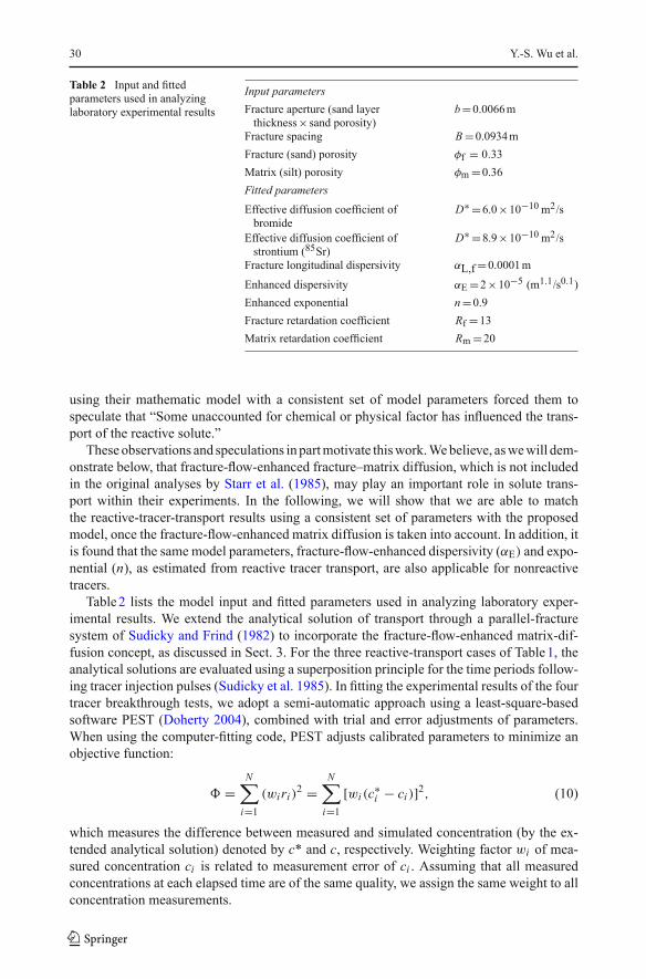
Table 2 Input and fittedparameters used in analyzinglaboratory experimental results
Input parametersFracture aperture (sand layerthickness× sand porosity)
b=0.0066m
Fracture spacing B=0.0934mFracture (sand) porosity φf = 0.33Matrix (silt) porosity φm =0.36Fitted parametersEffective diffusion coefficient ofbromide
D∗ =6.0×10⁻¹⁰ m2/s
Effective diffusion coefficient ofstrontium (85Sr)
D∗ =8.9×10⁻¹⁰ m2/s
Fracture longitudinal dispersivity αL,f=0.0001m
Enhanced dispersivity αE =2×10⁻⁵ (m1.1/s0.1)Enhanced exponential n=0.9Fracture retardation coefficient Rf =13Matrix retardation coefficient Rm =20
using their mathematic model with a consistent set of model parameters forced them tospeculate that “Some unaccounted for chemical or physical factor has influenced the trans-port of the reactive solute.”
These observations and speculations in partmotivate thiswork.Webelieve, aswewill dem-onstrate below, that fracture-flow-enhanced fracture–matrix diffusion, which is not includedin the original analyses by Starr et al. (1985), may play an important role in solute trans-port within their experiments. In the following, we will show that we are able to matchthe reactive-tracer-transport results using a consistent set of parameters with the proposedmodel, once the fracture-flow-enhanced matrix diffusion is taken into account. In addition, itis found that the same model parameters, fracture-flow-enhanced dispersivity (αE) and expo-nential (n), as estimated from reactive tracer transport, are also applicable for nonreactivetracers.
Table2 lists the model input and fitted parameters used in analyzing laboratory exper-imental results. We extend the analytical solution of transport through a parallel-fracturesystem of Sudicky and Frind (1982) to incorporate the fracture-flow-enhanced matrix-dif-fusion concept, as discussed in Sect. 3. For the three reactive-transport cases of Table1, theanalytical solutions are evaluated using a superposition principle for the time periods follow-ing tracer injection pulses (Sudicky et al. 1985). In fitting the experimental results of the fourtracer breakthrough tests, we adopt a semi-automatic approach using a least-square-basedsoftware PEST (Doherty 2004), combined with trial and error adjustments of parameters.When using the computer-fitting code, PEST adjusts calibrated parameters to minimize anobjective function:
� =N
∑
i=1(wi ri )2 =
N∑
i=1[wi (c∗i − ci )]2, (10)
which measures the difference between measured and simulated concentration (by the ex-tended analytical solution) denoted by c* and c, respectively. Weighting factor wi of mea-sured concentration ci is related to measurement error of ci . Assuming that all measuredconcentrations at each elapsed time are of the same quality, we assign the same weight to allconcentration measurements.
123

Fracture-Flow-Enhanced Matrix Diffusion in Solute Transport 31
Fig. 3 Observed and simulatedbreakthrough curves fornonreactive tracer. Simulatedbreakthrough curves includethose of Starr et al. (1985) andwith fracture-flow-enhanceddiffusion
For the case of nonreactive tracer transport, the calibrated or fitted parameters are: effectivematrix-diffusion coefficient (D∗), fracture-flow-enhanced dispersivity (αE), and exponential(n). Figure 3 shows an overall better match to the measurements when the fracture-flow-enhanced matrix-diffusion concept (labeled as “Simulated”) is included and when it is not(labeled as “Starr et al.”). In this case, the total enhancement (defined as the percentage of the2nd term over the first term, diffusion-only coefficient, in Eq. 6) is 12.7%, indicating matrixdiffusion being significantly enlarged by fracture flow.
For the tests of reactive transport, in addition to D∗, αE, and n, fracture and matrixretardation coefficients are also fitted. The semi-automatic approach combining PEST andtrial-and-error parameter calibration is used for Test 3 with velocity 0.5m/day to obtain theoptimum parameters (Table2) in a least-square sense. These parameters are then used tosimulate Tests 2 and 4. The final comparisons for the three tests of reactive transport casesare shown in Fig. 4. Note that a set of consistent physical parameters is estimated and usedwith the extended analytical solutions in our analyses, e.g., the same two retardation coef-ficients, Rf and Rm, are used for the three 85Sr transport tests through the fracture–matrixsystem (Fig. 2). In addition, the same enhanced parameters αE and n, induced by fractureflow, are found to work for both nonreactive and reactive transport results. Figure 4 showsthat accounting for the fracture-flow-enhancedmatrix-diffusion concept enables themodel tomatch all three 85Sr breakthrough curves at the three velocities reasonably well, as comparedwith the fittings by Starr et al. 1985, which unphysically uses different or velocity-dependentretardation factors for the same tracer transport in the same system. Even though compar-isons in Fig. 4 indicate that the current work yields a similar good fit when compared withthe original Starr et al. work, it is considered significant because the current study is basedon the same physically consistent parameters, once incorporating the fracture-flow-enhanced
123

32 Y.-S. Wu et al.
Fig. 4 Observed and simulated breakthrough curves for reactive tracer under three injection flow rates. Sim-ulated breakthrough curves include those of Starr et al. (1985) and with fracture-flow-enhanced diffusion
matrix-diffusion concept. In this case, the enhancements in matrix diffusion by fracture floware 26.7%, 13.9%, and 7.47%, respectively, for the three velocities of Fig. 4.
As shown in Figs. 3 and 4, the ability to match the laboratory measurements for bothnonreactive and reactive tracer transport, using the same flow and transport properties forthe same tracer tests, suggests that our proposed fracture-flow-enhanced matrix-diffusionconcept is consistent with the behavior of the experimental physical system. However, thereare still some inconsistencies when comparing the laboratory and model results, as shownin Fig. 4. In particular, long, smearing tails appear in the model predictions at a later time,when compared against the observations in Fig. 4 for the reactive transport scenario. Thesephenomena imply that there are still some unaccounted processes in our model, such as the
123

Fracture-Flow-Enhanced Matrix Diffusion in Solute Transport 33
possible effect of immobile regions around sand grains (e.g., van Genuchten and Dalton1986). Further discussion of the possible effects of different processes is considered beyondthe scope of this study.
5 Concluding Remarks
We present a new matrix diffusion enhancement conceptual model that correlates effectivefracture–matrix-diffusion coefficients to fracture-flow velocity. The new conceptual modelis physically based on the boundary-layer theory, and it indicates that solute transport bydiffusion between fractures and low-permeability matrix can be significantly enhanced andbecome a dominant factor if rapid flow occurs along the fracture–matrix interface, and iflarge transverse velocity and concentration gradients are created at fracture–matrix inter-faces. We demonstrate that the new proposed mathematical model for describing fracture-flow-enhanced matrix diffusion can be easily incorporated into existing analytical solutionsand numerical models to handle solute transport through fractured rock.
In an effort to provide some evidence of preliminary validation of the proposed enhancedmatrix diffusion concept, we apply the conceptual model to analyzing laboratory experimen-tal data for nonreactive and reactive tracer breakthrough tests. The experimental analysesindicate that the proposed matrix diffusion enhancement concept can provide not only a bet-ter agreement with experimental results for both nonreactive and reactive tracer transport, butalso a physically consistent set of flow and transport properties, which cannot otherwise beobtainedwithout incorporating the fracture-flow-enhancedmatrix diffusion process. The newconceptual model will be further validated using field experiments in complicated fracturesystem and using numerical modeling.
Acknowledgments The authors would like to thank Guoping Lu and Dan Hawkes for their review of thearticle.
References
Berkowitz, B.: Characterizing flow and transport in fractured geological media: A Review. Adv.Water Resour.25, 861–884 (2002). doi:10.1016/S0309-1708(02)00042-8
Bird, R.B., Steward, W.E., Lightfoot, E.N.: Transport Phenomena. Wiley, New York (1960)Doherty, J.: PEST Model-Independent Parameter Estimation. Watermark Numerical Computing, Australia
(2004)Fahien, R.W.: Fundamentals of Transport Phenomena. McGraw-Hill, New York (1983)Hu, Q., Kneafsey, T.J., Roberts, J.J., Tomutsa, L., Wang, J.S.: Characterizing unsaturated diffusion in porous
tuff gravel. Vadose Zone J. 3, 1425–1438 (2004)Huyakorn, P.S., Lester, B.H., Mercer, J.W.: An efficient finite element technique for modeling transport
of fractured porous media, 1. Single species transport. Water Resour. Res. 19(3), 841–854 (1983).doi:10.1029/WR019i003p00841
Liu, H.H., Haukwa, C.B., Ahlers, C.F., Bodvarsson, G.S., Flint, A., Guertal, W.B.: Modeling flow and trans-port in unsaturated fractured rocks: An evaluation of the continuum approach. J. Contam. Hydrol. 62–63,173–188 (2003). doi:10.1016/S0169-7722(02)00170-5
Liu, H.H., Salve, R., Wang, J.S., Bodvarsson, G.S., Hudson, D.: Field investigation into unsaturated flow andtransport in a fault: Model analysis. J. Contam. Hydrol. 74, 39–59 (2004a). doi:10.1016/j.jconhyd.2004.02.004
Liu, H.H., Bodvarsson, G.S., Zhang, G.: The scale-dependency of the effective matrix diffusion coefficient.Vadose Zone J. 3, 312–315 (2004)
Lu,G., Sonnenthal, E.L., Bodvarsson,G.S.: Implications of halide leaching on 36Cl studies atYuccaMountain,Nevada. Water Resour. Res. 39(12), 3-1–3-15 (2003)
123

34 Y.-S. Wu et al.
Maloszewski, A., Zuber, A.: Tracer experiments in fractured rocks: Matrix diffusion and validity of models.Water Resour. Res. 29(8), 2723–2735 (1993). doi:10.1029/93WR00608
Neretnieks, I.: Diffusion in the rock matrix: An important factor in radionuclide Neretnieks, I. Diffusion in therock matrix: An important factor in radionuclide retardation? J. Geophys. Res. 85, 4379–4397 (1980).doi:10.1029/JB085iB08p04379
Neretnieks, I., Eriksen, T., Tahtinen, P.: Tracer movement in a single fissure in granitic rock: Some exper-imental results and their interpretation. Water Resour. Res. 18(4), 849–858 (1982). doi:10.1029/WR018i004p00849
Ozisik, M.N.: Heat Transfer: A Basic Approach. McGraw-Hill, New York (1985)Pruess, K., Narasimhan, T.N.: A practical method for modeling fluid and heat flow in fractured porous media.
Soc. Pet. Eng. J. 25, 14–26 (1985). doi:10.2118/10509-PARasmuson, A., Narasimhan, T.N., Neretnieks, I.: Chemical transport in a fissured rock: Verification of a
numerical model. Water Resour. Res. 18(3), 1479–1492 (1982). doi:10.1029/WR018i005p01479Reimus, P.W., Callahan, T.J.: Matrix diffusion rates in fractured volcanic rocks at the Nevada Test Site: Evi-
dence for a dominant influence of effective fracture aperture. Water Resour. Res. 43, (2007). W07421.doi:10.1029/2006WR005746
Starr, R.C., Gillgam, R.W., Sudicky, E.A.: Experimental investigation of solute transport in stratifiedporous media, 1. The nonreactive case. Water Resour. Res. 21(7), 1035–1041 (1985). doi:10.1029/WR021i007p01043
Sudicky, E.A., Frind, E.O.: Contaminant transport in fractured porous media: Analytical solutions for a systemof parallel fractures. Water Resour. Res. 18(6), 1634–1642 (1982). doi:10.1029/WR018i006p01634
Sudicky, E.A., Gillgam, R.W., Frind, E.O.: Experimental investigation of solute transport in stratifiedporous media, vol. 2. The reactive case. Water Resour. Res. 21(7), 1043–1050 (1985). doi:10.1029/WR021i007p01035
Tang, D.H., Frind, E.O., Sudicky, E.A.: Contaminant transport in fractured porous media: Analytical solutionsfor a single fractures. Water Resour. Res. 17(3), 555–564 (1981). doi:10.1029/WR017i003p00555
van Genuchten, M.T., Dalton, F.N.: Models for simulating salt movement in aggregated field soils. Geoderma38, 165–183 (1986). doi:10.1016/0016-7061(86)90013-3
Warren, J.E., Root, P.J.: The behavior of naturally fractured reservoirs. Soc. Pet. Eng. J. 3(3), 245–255 (1963).doi:10.2118/426-PA
Wu, Y.S., Ahlers, C.F., Fraser, P., Simmons, A., Pruess, K.: Software Qualification of Selected TOUGH2Modules, Report LBL-39490; UC-800. Lawrence Berkeley National Laboratory, Berkeley, CA (1996)
Wu, Y.S., Pruess, K.: Numerical simulation of non-isothermal multiphase tracer transport in heterogeneousfractured porous media. Adv. Water Resour. 23, 699–723 (2000). doi:10.1016/S0309-1708(00)00008-7
Wu,Y.S., Liu, H.H., Bodvarsson, G.S.: A triple-continuum approach formodeling flow and transport processesin fractured rock. J. Contam. Hydrol. 73, 145–179 (2004). doi:10.1016/j.jconhyd.2004.01.002
123