fracture mode control: a bio-inspired strategy to combat
TRANSCRIPT

Fracture mode control: a bio-inspiredstrategy to combat catastrophic damageHaimin Yao1, Zhaoqian Xie1, Chong He1 & Ming Dao2
1Department of Mechanical Engineering, the Hong Kong Polytechnic University, Hung Hom, Kowloon, Hong Kong SAR, China,2Department of Materials Science and Engineering, Massachusetts Institute of Technology, Cambridge, MA 02139, USA.
The excellent mechanical properties of natural biomaterials have attracted intense attention fromresearchers with focus on the strengthening and toughening mechanisms. Nevertheless, no material isunconquerable under sufficiently high load. If fracture is unavoidable, constraining the damage scope turnsto be a practical way to preserve the integrity of the whole structure. Recent studies on biomaterials haverevealed that many structural biomaterials tend to be fractured, under sufficiently high indentation load,through ring cracking which is more localized and hence less destructive compared to the radial one.Inspired by this observation, here we explore the factors affecting the fracture mode of structuralbiomaterials idealized as laminated materials. Our results suggest that fracture mode of laminated materialsdepends on the coating/substrate modulus mismatch and the indenter size. A map of fracture mode isdeveloped, showing a critical modulus mismatch (CMM), below which ring cracking dominates irrespectiveof the indenter size. Many structural biomaterials in nature are found to have modulus mismatch close to theCMM. Our results not only shed light on the mechanics of inclination to ring cracking exhibited bystructural biomaterials but are of great value to the design of laminated structures with better persistence ofstructural integrity.
Biological competition between predator and prey happens ubiquitously in nature. Through millions ofyears’ evolution, organisms have developed diverse strategies to enhance their chance of survival. Forexample, animals such as fishes, turtles and snails, tend to equip themselves with hard exoskeletons to
protect their vulnerable bodies. The survival of these species through biological competitions proved the successof the adopted biological materials in protection against the mechanical attacks and may imply ingenious designconceptions potentially applicable to the synthetic protective materials in engineering. In recent decades, intens-ive efforts1–4 have been devoted to the studies on bioarmors in an attempt to understand the underlying principlesfor material design. So far, most works have been focusing on the mechanisms accounting for the excellentmechanical properties such as higher strength and toughness compared to their building constituents5–13, inspir-ing a number of biomimetic endeavors14–17. Despite the strengthening and toughening mechanisms whichincrease the difficulty of crack formation and propagation in materials, fracture is still unavoidable when over-whelming loading is encountered. Under this circumstance, reducing the scope of damage to the minimum extentbecomes a realistic choice to combat the catastrophic damage which is vital to the survival of the individuals andeven the species. Such strategy is believed to be present in nature after reviewing the findings of recent studies onstructural biomaterials. For instance, it has been reported that indentation on the scale of Polypterus senegalus, a‘living-fossil’ fish species, normally causes ring cracks rather than radial ones1. Such inclination to ring cracks wasalso exhibited by the shell of Crysomallon squamiferum18, a snail species inhabiting in deep sea hydrothermalenvironment, and teeth of Mylopharyngodon piceus (see Fig. 1a), a fish species feeding on mollusks19; but it is notoften the case in synthetic systems such as glass coating on polymeric substrate20 (Fig. 1b) and dental crown21.From the perspective of overall structural integrity, ring cracks are more localized and therefore less destructivethan the radial ones. Is the inclination to ring cracking exhibited by the above-mentioned biological structuralmaterials an accidental phenomenon or a consequence of evolution? If it results from natural selection, what arethe geometrical and mechanical features of the structural materials that regulate their fracture modes underindentation? Are there any guidelines that we can follow to control the fracture modes as desired? Speculation ofthese questions inspires us to investigate the mechanics of fracture modes of biological materials undergoingexternal load represented by indentation.
For a material free of pre-existing defects, fracture due to external loadings tends to start from crack initiation,followed by crack propagation. The location of the crack initiation and the orientation of the resulting crack planedepend on the stress field developed by the external loading, and the anisotropy, inhomogeneity and ‘‘mechanical
OPEN
SUBJECT AREAS:BIOINSPIRED MATERIALS
MECHANICAL ENGINEERING
Received21 October 2014
Accepted22 December 2014
Published26 January 2015
Correspondence andrequests for materials
should be addressed toH.Y. (mmhyao@polyu.
edu.hk)
SCIENTIFIC REPORTS | 5 : 8011 | DOI: 10.1038/srep08011 1

nature’’ of the material. For example, a homogeneous and isotropiccylinder specimen, when subjected to uniaxial tension, generallybreaks along the plane perpendicular to the longitudinal axis if it ismade by brittle material while fractures along conical surface at 45uto the longitudinal axis if it is made by ductile material. This isbecause brittle materials generally fail along the plane with max-imum tensile stress while the ductile materials often fail along theplane having maximum shear stress. To predict the onset of crackinitiation as well as the orientation of the resulting crack plane,setting a proper failure criterion is necessary. Due to the lack of auniversal failure criterion, various failure criteria have beendeveloped for materials with diverse mechanical natures22. Forexample, the simple maximum-tensile-stress criterion, also knownas Rankine criterion23, states that a crack forms when the maximumtensile principal stress (s1) exceeds the fracture strength (sf) of thematerial. It applies to brittle and even quasi-brittle materials such asconcrete, rocks, minerals and ceramics if the materials’ anisotropyand inheterogeneity are negligible. The plane of the resulting crackpredicted by the Rankine criterion is perpendicular to the directionof the maximum principal stress. Considering that most structuralbiomaterials are biomineralized composites with brittle minerals(e.g. calcium carbonate and hydroxyapatite) being their major con-stituents, Rankine criterion23 is considered suitable for them.
Most structural biomaterials in nature exhibit laminated micro-structures. For example, the shell of Crysomallon squamiferum con-sists of a compliant organic layer sandwiched by the outer ironsulfide layer and inner calcium carbonate layer18; the scale ofPolypterus senegalus comprises four layers including ganoine, dent-ine, isopedine and bone1; the tooth of Mylopharyngodon piceus iscomposed of enameloid and dentine layers19. Although these lami-nated structures display great diversity, common features in struc-ture and mechanical property are still present. For example, the mostouter layer in these structures is found to be notably stiffer andthinner than the adjacent layer. We thus speculate that the fracturemodes of laminated structures may depend on the layout of thick-nesses and mechanical properties in different layers. To shed light onthe factors affecting the fracture modes, theoretical modeling is car-ried out within the framework of contact mechanics.
ResultsTheoretical modeling. Consider an idealized bilayer structureconsisting of an elastic coating firmly attached on an elasticsubstrate, as shown in Fig. 2a. The elastic moduli and Poisson’sratios of the coating and substrate are denoted by Ec, Es, nc and ns,respectively. Although structural biomaterials in nature often consistof layers more than two, this simplified bilayer model is stillapplicable considering that the most outer layer is normally much
thinner than the adjacent layer. A rigid (non-deformable) sphericalindenter is compressed by force P onto the laminated structure,simulating the external attack from, for example, predators.Friction between the indenter and coating is neglected. Followingthe convention in contact mechanics, the profile of the sphericalindenter is approximated by a paraboloid of revolution describedby f rð Þ~r2=2R (see Fig. 2a), where R is the tip radiuscharacterizing the dimension of the indenter. According to theRankine criterion, the prediction of fracture modes entails theknowledge of the maximum principal stress s1 especially its peakvalue(s) and location(s) of emergence.
Evolution of the maximum stress. The contact problem posedabove has been extensively studied in literature24–28. Previousresults indicated two possible locations of the maximum principalstress s1 on the coating surface (z 5 0) and the axis of symmetry (r 5
0) respectively, as illustrated in Fig. 2b, c. In both cases, s1 was foundto be along the radial direction. Therefore, these two local peaks of s1
represent the maximum radial stresses on the coating surface (CS)and along the axis of symmetry (AoS) respectively. The existence oftwo local peaks of s1 on CS and AoS has also been reported inmaterials with continuously graded Young’s modulus29,30. Inparticular, for materials with exponentially graded Young’smodulus29 along the depth direction, E/ eaz, the maximum of s1
occurs at the contact perimeter when a . 0 while below thesurface along the z-axis when a , 0.
It can be shown that (Supplementary Information) the radialstress components in the coating can be expressed asE�c tpR
�s(�r,�z,�a,Ec
Es,nc,ns), where E�c ~
Ec
1{n2c
is the reduced modulus of
coating, t denotes the thickness of the coating, normalized radialstress �s(:) is a dimensionless function of the normalized coordinates
�r~rt
, �z~zt
and four non-dimensional parameters including the
normalized contact radius �a~at
, modulus ratio Ec/Es, Poisson’s
ratios vc and vs. Given these four non-dimensional parameters, thenormalized maximum principal stress �s1:s1pR=E�c t can beobtained semi-analytically for any point with normalized coordi-nates �r and �z(Supplementary Information). For example, takingEc/Es 5 4.0, vc 5 vs 5 0.3, the calculated distributions of �s1 alongAoS (r 5 0) and CS (z 5 0) at different contact radii are shown inFig. 3a and b, respectively. It can be seen that the maximum principalstress along the AoS increases monotonically from compressive totensile as the depth z increases. It reaches the peak value, denoted bysAoS
1
� �pk, at the coating/substrate interface (z 5 t). In contrast, on the
CS the location of the peak s1 is not fixed but changes with thecontact radius. Fig. 3b shows that the peak s1 on the CS occurs
Figure 1 | (a) Ring cracks created by indentation on the occlusal surface of a black carp tooth. (b) Radial cracks produced by indentation on a glass
coating attached on epoxy substrate.
www.nature.com/scientificreports
SCIENTIFIC REPORTS | 5 : 8011 | DOI: 10.1038/srep08011 2

exactly at the contact perimeter (r 5 a, z 5 0) when the contactradius a is relatively small in comparison with the coating thicknesst. With the increase of contact radius a, the s1 at the contact peri-meter decreases while that outside the contact region rises and finallyexceeds the former. The peak value of s1 on the CS, no matter whereit occurs, is denoted by sCS
1
� �pk.
As indicated by Rankine criterion23, cracking takes place if themaximum tensile principal stress s1 reaches the fracture strengthsf of the material. The presence of two local peaks of s1 underindentation implies two possible fracture modes. If sCS
1
� �pk reaches
sf first, ring cracking would happen as the plane of the resulting crackshould be perpendicular to the direction of the sCS
1
� �pk which is
along the radial direction. Otherwise, radial cracking would beinitiated first as the crack should be on the plane passing throughthe AoS. The determination of the initial fracture mode entails thecomparison between sCS
1
� �pk and sAoS
1
� �pk. Fig. 4a shows the evolu-
tion of sCS1
� �pk and sAoS
1
� �pk as functions of normalized contact
radius when Ec/Es 5 4.0 and vc 5 vs50.3. It can be seen that at smallcontact size, sCS
1
� �pk is greater than sAoS
1
� �pk. As indentation pro-
ceeds and contact radius increases, sAoS1
� �pk exceeds sCS
1
� �pk. But
the predominance of sAoS1
� �pk over sCS
1
� �pkis not lasting. With fur-
ther increase of the contact radius, sAoS1
� �pkwould not increase all the
way. Instead, there is a critical contact radius, at whichsAoS
1
� �pkreaches its maximum and then decreases. After certain con-
tact radius, sAoS1
� �pk is surpassed by sCS
1
� �pk. Since the fracture mode
of the coating depends on whether sAoS1
� �pk or sCS
1
� �pk reaches the
fracture strength first as indentation proceeds, the varying contrast
between sAoS1
� �pkand sCS
1
� �pk shown above implies the dependence
of fracture mode on the fracture strength. For the case with Ec/Es 5
4.0 and vc 5 vs 5 0.3, Fig. 4a shows that if the normalized fracturestrength is either sufficiently low or high, sCS
1
� �pk would reach the
fracture strength first, therefore resulting in ring crack. The lowerand upper thresholds of the normalized fracture strength for ringcracking can be readily determined from Fig. 4a to be around 0.05and 0.9. Here normalized fracture strength is defined as�sf:sfpR=E�c t. If �sf v0:05 or �sf w0:9 ring cracking occurs.Otherwise, radial cracking takes place. It should be noted that thelower and upper thresholds of the normalized fracture strength forring/radial cracking are functions of modulus ratio Ec/Es, andPoisson’s ratios vc and vs. Given vc and vs, they are found to convergeas Ec/Esdecreases. There exists a critical value of Ec/Es, at which theyconverge to one value. For the case of vc 5 vs 5 0.3, this criticalmodulus ratio is found to be around 1.6, at which the evolution of thenormalized sCS
1
� �pk and sAoS
1
� �pk is displayed in Fig. 4b. If Ec/Es is
lower than this critical value, sCS1
� �pk is always higher than sAoS
1
� �pk
irrespective of the contact radius. In that case, ring cracking isexpected to occur first irrespective of the value of �sf . Recalling thedefinition of the normalized fracture strength �sf:psf R=E�c t, thevalue of �sf depends not only on the geometrical and mechanicalproperties of the laminated materials under indentation but alsoon the dimension of the indenter characterized by the tip radius R.If the modulus ratio Ec/Es is lower than the critical value mentionedabove, the advent of ring cracking is ensured irrespective of theindenter radius. Such critical value of Ec/Es is therefore termed asthe critical modulus mismatch (CMM) for ensuring ring crackingmode. For homogenous case with Ec/Es 5 1.0 and vc 5 vs, our resultsshow that the maximum tensile stress always occurs on the coating
Figure 2 | (a) Schematic of an elastic coating/substrate structure under indentation by a rigid indenter. The peak value of the maximum tensile principal
stress, (s1)pk, for the contact problem in (a) may occur at two possible positions. One is along the axis of symmetry at the coating/substrate
interface as shown in (b), and another one is on the coating surface near the contact perimeter as shown in (c). Here normalized maximum principal stress
is defined as �s1:s1pR=E�c t.
www.nature.com/scientificreports
SCIENTIFIC REPORTS | 5 : 8011 | DOI: 10.1038/srep08011 3

surface along the radial direction. Therefore, ring cracking, instead ofradial cracking, occurs first for brittle materials. This conclusion isconsistent with the prediction of the classic Hertzian theory31.
Fracture mode map. The dependence of fracture mode on stiffnessratio Ec/Es and normalized fracture strength �sf can be systematicallydepicted by a map in terms of these two nondimensional parameters,as shown in Fig. 5 for the case of vc 5 vs 5 0.3. It can be seen that a v-shaped curve divides the plane into two regions corresponding toradial cracking and ring cracking respectively. The valley point of thev-shaped boundary corresponds to the scenario with CMM. It showsagain that the destructive radical cracking can be inhibited ordeferred for indenters of any size as long as the modulus ratio Ec/Es is lower than the CMM.
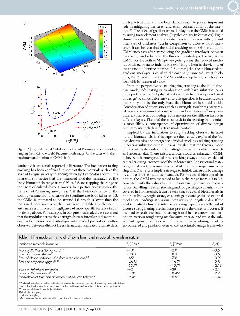
It should be pointed out that the CMM revealed above depends onthe Poisson’s ratios of both coating and substrate. To gain a deeperinsight into the effect of Poisson’s ratios on the CMM, we studied aseries of cases with vc and vs in the reasonably broad range from 0.1 to0.4. Fig. 6a shows the variation of CMM as a function of vc and vs. Itcan be seen that CMM is proportional to vs while inversely propor-tional to vc. Therefore, CMM reaches its maximum and minimum atvc 5 0.1, vs 5 0.4, and vc 5 0.4, vs 5 0.1 respectively. The corres-ponding maps of fracture mode for these two limiting cases aredisplayed in Fig. 6b. In comparison to the case with vc 5 vs5 0.3shown in Fig. 5, it can be seen that the territory of radical crackingregime shrinks in the case of vc 5 0.1, vs 5 0.4 while expands in thecase of vc 5 0.4, vs 5 0.1, resulting in CMMs equal to 3.3 and 1.0respectively.
DiscussionFor the laminated biomaterials in nature, it may not be easy to obtainthe precise Poisson’s ratio for each layer and then to predict the
corresponding CMM. However, if we take 0.1–0.4 as the reasonablerange of Poisson’s ratio of biomaterials, the CMM of natural lami-nated biomaterials, in the light of Fig. 6a, is estimated ranging from1.0 to 3.3. It is interesting to compare this theoretical prediction withthe measured value. Table 1 listed the modulus mismatch of some
Figure 3 | (a) Variation of the normalized maximum principal stress
along the axis of symmetry (r 5 0), and (b) coating surface (z 5 0).
Figure 4 | Variation of the peak principal stresses on the coating surfaceand the axis of symmetry with the normalized contact radius for(a) Ec/Es 5 4.0, nc 5 ns 5 0.3, and (b) Ec/Es 5 1.6, nc 5 ns 5 0.3.
Figure 5 | Fracture mode map for case with Poisson’s ratios nc 5 ns 5 0.3.
www.nature.com/scientificreports
SCIENTIFIC REPORTS | 5 : 8011 | DOI: 10.1038/srep08011 4
laminated biomaterials reported in literature. The inclination to ringcracking has been confirmed in some of these materials such as thescale of Polypterus senegalus being bitten by its predator’s teeth1. It isinteresting to notice that the measured modulus mismatch of thelisted biomaterials range from 0.93 to 3.6, overlapping the range ofthe CMM calculated above. However, for a particular case such as theteeth of Mylopharyngodon piceus19, if the Poisson’s ratios of thecoating (enameloid) and substrate (dentine) are both taken as 0.3,the CMM is estimated to be around 1.6, which is lower than themeasured modulus mismatch 3.5 as shown in Table 1. Such discrep-ancy may result from our negligence of more specific features in ourmodeling above. For example, in our previous analysis, we assumedthat the modulus across the coating/substrate interface is discontinu-ous. In fact, transitional interlayer with graded properties is oftenobserved between distinct layers in natural laminated biomaterials.
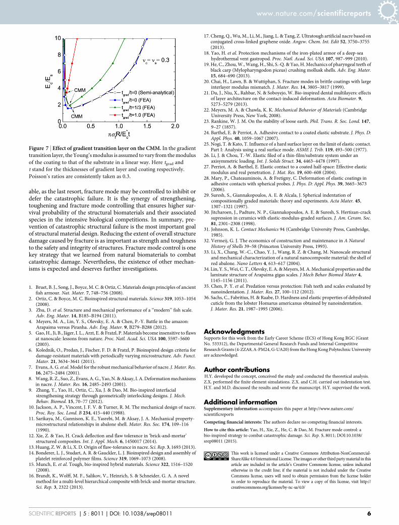
Such gradient interlayer has been demonstrated to play an importantrole in mitigating the stress and strain concentration at the inter-face1,18. The effect of gradient transition layer on the CMM is studiedby using finite element analysis (Supplementary Information). Fig. 7shows the calculated fracture mode maps for the cases with gradientinterlayer of thickness tgrad in comparison to those without inter-layer. It can be seen that the radial cracking regime shrinks and theCMM increases after introducing the gradient interlayer betweenthe coating and substrate. The thicker the interlayer, the higher theCMM. For the teeth of Mylopharyngodon piceus, the reduced modu-lus obtained by nano-indentation exhibits gradient in the vicinity ofthe enameloid/dentine interface19. Assuming that the thickness of thegradient interlayer is equal to the coating (enameloid layer) thick-ness, Fig. 7 implies that the CMM could rise up to 3.5, which agreeswell with its measured value.
From the perspective of ensuring ring cracking as the initial frac-ture mode, soft coating in combination with hard substrate seemsmore preferable. But why do natural materials barely adopt such kindof design? A conceivable answer to this question is because fracturemode may not be the only issue that biomaterials should tackle.Consideration of other issues such as strength, toughness, wear res-istance and economics of construction and maintenance32 may raisedifferent and even competing requirements for the stiffness layout indifferent layers. The modulus mismatch in the existing biomaterialsis most likely a consequence of optimization of diverse designrequirements including fracture mode control.
Inspired by the inclination to ring cracking observed in mostnatural biomaterials, in this paper we theoretically explored the fac-tors determining the emergence of radial cracking and ring crackingin coating/substrate systems. It was revealed that the fracture modeof the coating depends on the coating/substrate modulus mismatchand indenter size. There exists a critical modulus mismatch, CMM,below which emergence of ring cracking always precedes that ofradical cracking irrespective of the indenter size. For structural mate-rials, radial cracking is much more catastrophic in comparison to thering one. Our results imply a strategy to inhibit catastrophic damageby controlling the modulus mismatch. For structural biomaterials innature, the CMM was estimated to be in the range from 1.0 to 3.3,consistent with the values found in many existing structural bioma-terials. Recalling the strengthening and toughening mechanisms dis-covered in biomaterials, it can be seen that structural biomaterials innature utilize synergic strategies to mitigate damage due to externalmechanical loadings at various intensities and length scales. If theload is relatively low, the intrinsic carrying capacity with the aid ofdiverse strengthening mechanisms prevents the onset of fracture. Ifthe load exceeds the fracture strength and hence causes crack ini-tiation, various toughening mechanisms operate and resist the sub-sequent growth of cracks. If indeed overwhelming load isencountered and partial or even whole structural damage is unavoid-
Figure 6 | (a) Calculated CMM as function of Poisson’s ratios nc and ns
ranging from 0.1 to 0.4; (b) Fracture mode maps for the cases with the
maximum and minimum CMMs in (a).
Table 1 | The modulus mismatch of some laminated structural materials in nature
Laminated materials in nature Ec (GPa)* Es (GPa)* Ec/Es
Tooth of M. Piceus 1(Black carp)19 ,70{ ,20{ ,3.5Shell of C. squamiferum18 ,28.8 ,8.0 ,3.6Shell of Haliotis rufescens (California red abalone)33 ,65{ ,70{ ,0.93Scale of Arapaimas gigas34,35 ,46.8{ ,16.7{ ,2.8
,33.7D ,15.7D ,2.15Scale of Polypterus senegalus1 ,62 ,29 ,2.1Scale of Morone saxatilis33 ,1.0{ ,0.45{ ,2.2Exoskeleton of Homarus americanus (American Lobster)36 ,9.4& ,6.6& ,1.42
*Modulus here refers to, unless indicated otherwise, the reduced modulus obtained by nano-indentation;1The occlusal surfaces of black carp teeth are flat and therefore laminated plate model is applicable;{Young’s modulus obtained by tensile tests;{Dehydrated samples;DHydrated samples;&Mean value of the reduced moduli in normal and transverse directions.
www.nature.com/scientificreports
SCIENTIFIC REPORTS | 5 : 8011 | DOI: 10.1038/srep08011 5
able, as the last resort, fracture mode may be controlled to inhibit ordefer the catastrophic failure. It is the synergy of strengthening,toughening and fracture mode controlling that ensures higher sur-vival probability of the structural biomaterials and their associatedspecies in the intensive biological competitions. In summary, pre-vention of catastrophic structural failure is the most important goalof structural material design. Reducing the extent of overall structuredamage caused by fracture is as important as strength and toughnessto the safety and integrity of structures. Fracture mode control is onekey strategy that we learned from natural biomaterials to combatcatastrophic damage. Nevertheless, the existence of other mechan-isms is expected and deserves further investigations.
1. Bruet, B. J., Song, J., Boyce, M. C. & Ortiz, C. Materials design principles of ancientfish armour. Nat. Mater. 7, 748–756 (2008).
2. Ortiz, C. & Boyce, M. C. Bioinspired structural materials. Science 319, 1053–1054(2008).
3. Zhu, D. et al. Structure and mechanical performance of a ‘‘modern’’ fish scale.Adv. Eng. Mater. 14, B185–B194 (2011).
4. Meyers, M. A., Lin, Y. S., Olevsky, E. A. & Chen, P.-Y. Battle in the amazon:Arapaima versus Piranha. Adv. Eng. Mater. 9, B279–B288 (2012).
5. Gao, H., Ji, B., Jager, I. L., Arzt, E. & Fratzl, P. Materials become insensitive to flawsat nanoscale: lessons from nature. Proc. Natl. Acad. Sci. USA 100, 5597–5600(2003).
6. Kolednik, O., Predan, J., Fischer, F. D. & Fratzl, P. Bioinspired design criteria fordamage-resistant materials with periodically varying microstructure. Adv. Funct.Mater. 21, 3634–3641 (2011).
7. Evans, A. G. et al. Model for the robust mechanical behavior of nacre. J. Mater. Res.16, 2475–2484 (2001).
8. Wang, R. Z., Suo, Z., Evans, A. G., Yao, N. & Aksay, I. A. Deformation mechanismsin nacre. J. Mater. Res. 16, 2485–2493 (2001).
9. Zhang, Y., Yao, H., Ortiz, C., Xu, J. & Dao, M. Bio-inspired interfacialstrengthening strategy through geometrically interlocking designs. J. Mech.Behav. Biomed. 15, 70–77 (2012).
10. Jackson, A. P., Vincent, J. F. V. & Turner, R. M. The mechanical design of nacre.Proc. Roy. Soc. Lond. B 234, 415–440 (1988).
11. Sarikaya, M., Gunnison, K. E., Yasrebi, M. & Aksay, J. A. Mechanical property-microstructural relationships in abalone shell. Mater. Res. Soc. 174, 109–116(1990).
12. Xie, Z. & Yao, H. Crack deflection and flaw tolerance in ‘brick-and-mortar’structured composites. Int. J. Appl. Mech. 6, 1450017 (2014).
13. Huang, Z. W. & Li, X. D. Origin of flaw-tolerance in nacre. Sci. Rep. 3, 1693 (2013).14. Bonderer, L. J., Studart, A. R. & Gauckler, L. J. Bioinspired design and assembly of
platelet reinforced polymer films. Science 319, 1069–1073 (2008).15. Munch, E. et al. Tough, bio-inspired hybrid materials. Science 322, 1516–1520
(2008).16. Brandt, K., Wolff, M. F., Salikov, V., Heinrich, S. & Schneider, G. A. A novel
method for a multi-level hierarchical composite with brick-and-mortar structure.Sci. Rep. 3, 2322 (2013).
17. Cheng, Q., Wu, M., Li, M., Jiang, L. & Tang, Z. Ultratough artificial nacre based onconjugated cross-linked graphene oxide. Angew. Chem. Int. Edit 52, 3750–3755(2013).
18. Yao, H. et al. Protection mechanisms of the iron-plated armor of a deep-seahydrothermal vent gastropod. Proc. Natl. Acad. Sci. USA 107, 987–999 (2010).
19. He, C., Zhou, W., Wang, H., Shi, S.-Q. & Yao, H. Mechanics of pharyngeal teeth ofblack carp (Mylopharyngodon piceus) crushing mollusk shells. Adv. Eng. Mater.15, 684–690 (2013).
20. Chai, H., Lawn, B. & Wuttiphan, S. Fracture modes in brittle coatings with largeinterlayer modulus mismatch. J. Mater. Res. 14, 3805–3817 (1999).
21. Du, J., Niu, X., Rahbar, N. & Soboyejo, W. Bio-inspired dental multilayers: effectsof layer architecture on the contact-induced deformation. Acta Biomater. 9,5273–5279 (2013).
22. Meyers, M. A. & Chawla, K. K. Mechanical Behavior of Materials (CambridgeUniversity Press, New York, 2008).
23. Rankine, W. J. M. On the stability of loose earth. Phil. Trans. R. Soc. Lond. 147,9–27 (1857).
24. Barthel, E. & Perriot, A. Adhesive contact to a coated elastic substrate. J. Phys. D:Appl. Phys. 40, 1059–1067 (2007).
25. Nogi, T. & Kato, T. Influence of a hard surface layer on the limit of elastic contact.Part I: Analysis using a real surface mode. ASME J. Trib. 119, 493–500 (1977).
26. Li, J. & Chou, T.-W. Elastic filed of a thin-film/substrate system under anaxisymmetric loading. Int. J. Solids Struct. 34, 4463–4478 (1997).
27. Perriot, A. & Barthel, E. Elastic contact to a coated half-space: Effective elasticmodulus and real penetration. J. Mat. Res. 19, 600–608 (2004).
28. Mary, P., Chateauminois, A. & Fretigny, C. Deformation of elastic coatings inadhesive contacts with spherical probes. J. Phys. D: Appl. Phys. 39, 3665–3673(2006).
29. Suresh, S., Giannakopoulos, A. E. & Alcala, J. Spherical indentation ofcompositionally graded materials: theory and experiments. Acta Mater. 45,1307–1321 (1997).
30. Jitcharoen, J., Padture, N. P., Giannakopoulos, A. E. & Suresh, S. Hertizan-cracksupression in ceramics with elastic-modulus-graded surfaces. J. Am. Ceram. Soc.81, 2301–2308 (1998).
31. Johnson, K. L. Contact Mechanics 94 (Cambridge University Press, Cambridge,1985).
32. Vermeij, G. J. The economics of construction and maintenance in A NaturalHistory of Shells 39–58 (Princeton University Press, 1993).
33. Li, X., Chang, W.-C., Chao, Y. J., Wang, R. Z. & Chang, M. Nanoscale structuraland mechanical characterization of a natural nanocomposite material: the shell ofred abalone. Nano Letters 4, 613–617 (2004).
34. Lin, Y. S., Wei, C. T., Olevsky, E. A. & Meyers, M. A. Mechanical properties and thelaminate structure of Arapaima gigas scales. J Mech Behav Biomed Mater 4,1145–1156 (2011).
35. Chen, P. Y. et al. Predation versus protection: Fish teeth and scales evaluated bynanoindentation. J. Mater. Res. 27, 100–112 (2012).
36. Sachs, C., Fabritius, H. & Raabe, D. Hardness and elastic properties of dehydratedcuticle from the lobster Homarus americanus obtained by nanoindentation.J. Mater. Res. 21, 1987–1995 (2006).
AcknowledgmentsSupports for this work from the Early Career Scheme (ECS) of Hong Kong RGC (GrantNo. 533312), the Departmental General Research Funds and Internal CompetitiveResearch Grants (4-ZZA8, A-PM24, G-UA20) from the Hong Kong Polytechnic Universityare acknowledged.
Author contributionsH.Y. developed the concept, conceived the study and conducted the theoretical analysis.Z.X. performed the finite element simulations. Z.X. and C.H. carried out indentation test.H.Y. and M.D. discussed the results and wrote the manuscript. H.Y. supervised the work.
Additional informationSupplementary information accompanies this paper at http://www.nature.com/scientificreports
Competing financial interests: The authors declare no competing financial interests.
How to cite this article: Yao, H., Xie, Z., He, C. & Dao, M. Fracture mode control: abio-inspired strategy to combat catastrophic damage. Sci. Rep. 5, 8011; DOI:10.1038/srep08011 (2015).
This work is licensed under a Creative Commons Attribution-NonCommercial-ShareAlike 4.0 International License. The images or other third party material in thisarticle are included in the article’s Creative Commons license, unless indicatedotherwise in the credit line; if the material is not included under the CreativeCommons license, users will need to obtain permission from the license holderin order to reproduce the material. To view a copy of this license, visit http://creativecommons.org/licenses/by-nc-sa/4.0/
Figure 7 | Effect of gradient transition layer on the CMM. In the gradient
transition layer, the Young’s modulus is assumed to vary from the modulus
of the coating to that of the substrate in a linear way. Here tgrad and
t stand for the thicknesses of gradient layer and coating respectively.
Poisson’s ratios are consistently taken as 0.3.
www.nature.com/scientificreports
SCIENTIFIC REPORTS | 5 : 8011 | DOI: 10.1038/srep08011 6
1
Supporting Information 1
Fracture mode control: a bio-inspired strategy to combat catastrophic 2
damage 3
Haimin Yaoa,1
, Zhaoqian Xiea, Chong He
a, Ming Dao
b 4
a Department of Mechanical Engineering, the Hong Kong Polytechnic University, Hung 5
Hom, Kowloon, Hong Kong 6
b Department of Materials Science and Engineering, Massachusetts Institute of 7
Technology, Cambridge, MA 02139, USA 8
9
Semi-analytical solution to the stress field 10
The contact problem posed in Fig. 2a has been systematically studied in the framework of 11
elasticity theory. The initial analytical investigation can date back to 1997 when Li and 12
Chou1 and Nogiand Kato
2 independently established the Green function for the coated 13
elastic substrate. Based on their work, Perriot and Barthel3 reformulated the problem by 14
introducing two cosine Fourier transform-based auxiliary functions, which enable the 15
problem to be solved at lower numerical cost. Subsequent extension from Hertzian 16
(non-adhesive) contact to adhesive contact was made by Mary et al.4 and Barthel and 17
Perriot5. 18
To predict the fracture mode on the basis of the Rankine criterion, the knowledge of 19
the maximum principal stress 1 especially its peak value(s) and occurring location(s) is 20
necessary. Although it is difficult the obtain the analytical solution to the field of 1 , 21
previous solutions in literature implies that the field of 1 exhibits two local peaks 22
occurring at the coating surface (z = 0) and axis of symmetry (r = 0) respectively6. Such 23
feature in the spacial distribution of 1 can be readily confirmed by finite element 24
analysis. Moreover, radial direction is found to be the principal direction of 1 on the 25
coating surface and axis of symmetry. Therefore, the peaks of 1 are equal to the 26
maximum radial stress r along the coating surface and the axis of symmetry 27
respectively; so that we just need to focus our attention on the solution to the radial stress 28
r . 29
1 To whom correspondence may be addressed. E-mail: [email protected] (H. Yao)
2
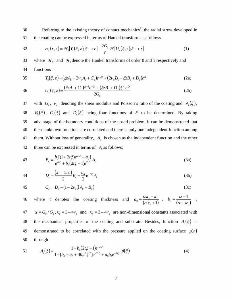
Referring to the existing theory of contact mechanics7, the radial stress developed in 30
the coating can be expressed in terms of Hankel transforms as follows 31
rzUr
GrzYzrr ;,
2;,, c1
cc0 HH (1) 32
where 0H and 1H denote the Hankel transforms of order 0 and 1 respectively and 33
functions 34
zz eDzBBeCAzAzY ccccccccc 22, (2a) 35
c
1cc
1cc
c2
,G
eDzBeCzAzU
zz
(2b) 36
with cG , c denoting the shear modulus and Poisson’s ratio of the coating and cA , 37
cB , cC and cD being four functions of to be determined. By taking 38
advantage of the boundary conditions of the posed problem, it can be demonstrated that 39
these unknown functions are correlated and there is only one independent function among 40
them. Without loss of generality, cA is chosen as the independent function and the other 41
three can be expressed in terms of cA as follows: 42
c20
4
02
0c
12
])21[(A
etbe
aetbB
tt
t
(3a) 43
c
20c
cc
22
2Ae
aB
tD t
(3b) 44
ccccc 21 BADC (3c) 45
where t denotes the coating thickness and 1s
cs0
a ,
c
0
1
b , 46
sc / GG , cc 43 and ss 43 are non-dimensional constants associated with 47
the mechanical properties of the coating and substrate. Besides, function cA is 48
demonstrated to be correlated with the pressure applied on the coating surface rp 49
through 50
pebaetbab
etbA
tt
t~
]4[1
1214
00222
000
20
c
(4) 51
3
where p~ is the Hankel transforms of order 0 of rp defined by 52
drrJrrpp 00
~
with 0J denoting the Bessel Function of the first kind of 53
order 0. However, solving cA through Eq. (4) is still difficult due to the mixed 54
boundary condition on the coating surface in this problem. To tackle this problem, 55
Barthel and coworkers8, 9
ingeniously introduced an auxiliary function sg , the cosine 56
Fourier transform of function p~ defined by 57
dspsg cos~0
( as ) (5) 58
and established an integral equation with respect to sg which, for Hertzian 59
(non-adhesive) contact, is given by 60
dgsKsg
ER
sa a
0*c
22
,2
as (6) 61
where a denotes the radius of the contact region, 2cc
*c 1/ EE with cE and c 62
being the Young’s modulus and Poisson’s ratio of the coating respectively, and 63
aKsKsK ,,, (7a) 64
dsebaetbab
ebaetbtbabsK
tt
tt
coscos)4(1
2)44(2,
0 4
00
222
000
4
00
2
0
22
000
(7b) 65
Using the coating thickness t as the characteristic length scale for normalization, Eqs. (6) 66
and (7) can be normalized to be 67
22 sa dgsKsga
0
, as (8) 68
aKsKsKtsK ,,,, 69
dsebaebab
ebaebbabsK coscos
)4(1
2)44(2,
0 4
00
22
000
4
00
2
0
2
000
70
where taa / , t/ , tss / ,
R
tEsgsg
2/
2*c , t . Subsequently, the 71
normalized p~ and cA are given by 72
4
R
tEpp
3*c~~ sdssg
a
cos0 (9) 73
400
22000
20
3*c
cc]4[1
121~
ebaebab
ebp
R
tEAA (10) 74
Then, the normalized form of other functions cB , cC , and cD can be given by 75
R
tEBB
3*c
cc c2
04
02
0
12
])21[(A
ebe
aeb
(11) 76
R
tEDD
3*c
cc
c20
cc
22
2Ae
aB
(12) 77
R
tECC
3*c
cc cccc 21 BAD (13) 78
The normalized radial stress can be given by 79
R
tEzrzr rr
*c,, rzU
rrzY ;,
1;, c1c0 HH (14) 80
where 81
R
tEYzY
3*c
cc , = zz eDBzBeCAzA )2(2 cccccccc (15a) 82
RG
tEUzU
c
4*c
cc2
, zz eDBzeCAz 1cc
1cc
(15b) 83
zz eBeAR
tEZzZ
cccc
3*c
cc 22,
(15c) 84
85
Although Eq. (14) gives the expression of the normalized radial stress, it involves 86
Hankel transforms of complicated functions which cannot be accomplished analytically. 87
Numerical approach has to be applied to obtain the normalized radial stress field. In this 88
regards, the obtained result is termed “semi-analytical” solution. 89
5
From above formulation, it can be seen that the influence of the mechanical 90
properties on the stress is exerted through parameters 0a , 0b , , c and s , which are 91
functions of three independent dimensionless constants s
c
E
E, c and s . From Eq. 92
(14), it can be noticed that the radial stress in coating can be expressed in terms of 93
),,,,,( sc
s
c*c a
E
Ezr
R
tEr
, where the normalized radial stress ),,,,,( sc
s
c aE
Ezrr is a 94
dimensionless function of normalized coordinates r and z , mechanical properties 95
characterized by s
c
E
E, c and s , and the normalized contact radius .a Given zr , , 96
s
c
E
E, c , s , the normalized radial stress can be calculated numerically by following a 97
procedure as follows. First, function sg is determined numerically by solving the 98
integral equation of Eq.(8). Then function p~ is obtained by taking the inversion of 99
cosine transform of function sg as shown in Eq. (9), followed by the determination of 100
function cA and its dependents cB , cD and cC through Eqs. (10-13). 101
Finally, the normalized radial stress zrr , is determined based on Eqs. (14-15). The 102
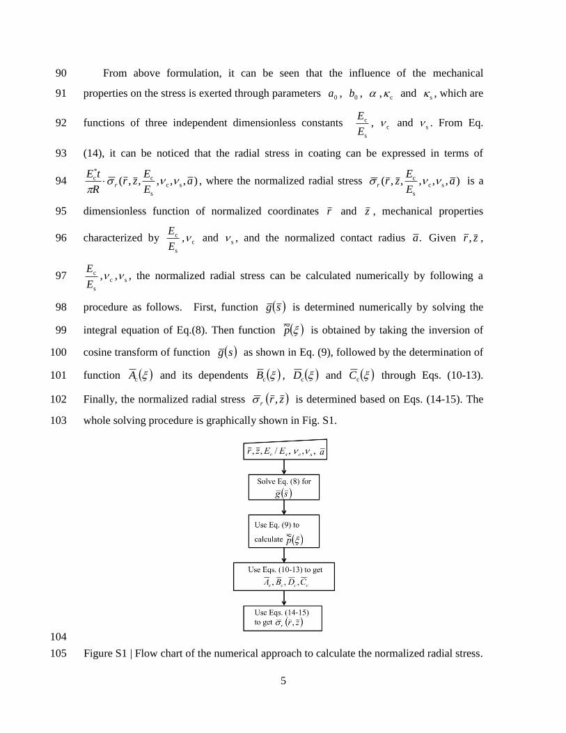
whole solving procedure is graphically shown in Fig. S1. 103
104
Figure S1 | Flow chart of the numerical approach to calculate the normalized radial stress. 105

6
FEA analysis of the effect of gradient interlayer on CMM 106
107
Figure S2 | Schematics of the FEA model for studying the effect of gradient 108
interlayer on fracture modes. 109
If a gradient interlayer is present between the coating and substrate, the problem may not 110
be able to be solved by analytical or semi-analytical approach as shown above. Finite 111
element analysis(FEA) has to be adopted to calculate the principal stress particularly its 112
peaks on the CS and AoS so as to predict the fracture modes. Fig. S2 shows the 113
schematics of the FEA model we used, in which a rigid spherical indenter is compressed 114
by external loading against a laminated material. Unlike the bilayer semi-analytical 115
model shown in Fig. 2, an additional gradient interlayer of thickness tgrad is introduced 116
between the coating and substrate. The interfaces between different layers are assumed 117
perfectly bonded. The width and thickness of the substrate are taken as 33 and 25 times 118
of the coating thickness t respectively, which are demonstrated large enough to eliminate 119
the boundary effect. The elastic gradient in the transition interlayer is achieved by 120
dividing it into 5 sub-layers, whose Young’s moduli are taken as the values determined 121
by linear interpolation in accordance to its distances to the coating and substrate. The 122
Poisson’s ratio in the whole model is uniformly taken as 0.3. The contact between 123
indenter and coating is assumed frictionless. Given modulus ratio Ec/Es between coating 124
and substrate, the indentation problem is simulated with commercial FEA software 125
ABAQUS (Dassault Systèmes) by using 4-node bilinear axisymmetric quadrilateral solid 126
element (CAX4R in ABAQUS). Sufficiently fine meshing is taken to ensure the mesh 127

7
convergence of the results. The evolution of the peaks of the principal stress on CS and 128
AoS with the contact size is obtained. By comparing the obtained peaks of the principal 129
stress with the fracture strength of the material, the condition for radical cracking and 130
ring cracking is obtained in terms of normalized fracture strength tER *cff / . Such 131
procedure is repeated for a series modulus ratio Ec/Es. A fracture modes map then is 132
obtained as we did in the case without gradient interlayer. The effect of gradient 133
interlayer thickness tgrad on the fracture modes is studied by taking tgrad=0, t/3 and t 134
respectively. The results are shown in Fig. 7 in comparison to that obtained by the 135
semi-analytical approach for the case without gradient interlayer. 136
137 138
References: 139 1. Li J, Chou T-W. Elastic filed of a thin-film/substrate system under an 140
axisymmetric loading. Int J Solids Struct 34, 4463-4478 (1997). 141
2. Nogi T, Kato T. Influence of a hard surface layer on the limit of elastic contact. 142
Part I: Analysis using a real surface mode. ASME J Trib 119, 493-500 (1977). 143
3. Perriot A, Barthel E. Elastic contact to a coated half-space: Effective elastic 144
modulus and real penetration. J Mat Res 19, 600-608 (2004). 145
4. Mary P, Chateauminois A, Fretigny C. Deformation of elastic coatings in 146
adhesive contacts with spherical probes. Journal of Physics D: Applied Physics 39, 147
3665-3673 (2006). 148
5. Barthel E, Perriot A. Adhesive contact to a coated elastic substrate. J Phys D: 149
Appl Phys 40, 1059-1067 (2007). 150
6. Chai H, Lawn B, Wuttiphan S. Fracture modes in brittle coatings with large 151
interlayer modulus mismatch. Journal of Materials Research 14, 3805-3817 152
(1999). 153
7. Gladwell GM. Contact Problem in the Classical Theory of Elasticity. Sijthoff & 154
Noordhoff (1980). 155
8. Huguet AS, Barthel E. Surface forces and the adhesive contact of axisymmetric 156
elastic bodies. J Adhes 74, 143-175 (2000). 157
9. Barthel E, Haiat G. Approximate model for the adhesive contact of viscoelastic 158
spheres. Langmuir 18, 9362–9370 (2002). 159
160
161