frc robot wiring - first in maryland · frc robot wiring baltimore area alliance first robotics...
TRANSCRIPT

FRC Robot Wiring
Baltimore Area Alliance FIRST Robotics
October 26, 2013

What We Will Cover
Basic concepts of electricity and circuits
Each part of the FRC circuit will be
discussed and wiring requirements
explained.
Details are based upon the 2013 FRC rules.

Basic Electricity Ohm's Law
Voltage = Current * Resistance or
Current = Voltage / Resistance or
Resistance = Voltage / Current
Batteries in series add their voltages, not their currents
Batteries in parallel add their current, not their voltages
Resistances or loads in series block more current and split voltage
Resistances or loads in parallel use more current and share the voltage

Series Parallel Example
Determine voltage and current in each part of the circuit
Parallel
resistance =
R1*R2/(R1+R2)

Power Power is calculated by multiplying voltage by
current to get watts, E x I = W
Amp hour ratings of batteries are only useful if based on a time to discharge. To discharge faster, derate by 10 to 30% or more as the battery ages
So with a 17 amp hour battery discharging over 2.25 minutes is capable of delivering:
17 * 60 / (1.3 * 2.25) = 348 amps continuously
While this might seem like a lot, one CIM motor has a 344 amp stall current. A 4-wheel drive with 4 CIM motors might each draw close to 40 amps.

Pieces Parts Battery, Wire, Main Circuit Breaker, Lugs
Power Distribution Board (PDB), Fuses, More Wire,
Terminals and Connectors
cRIO, Digital Modules, Analog Modules
Digital Sidecar, D-sub Cable, Wiring Connections
Analog Breakout Board, Cabling
Bridge, Power Converter, Cabling
Jag, Victor, Talon, Vex, Servo, Power Wiring, Motor
Wiring, Signal Wiring
Compressor, Solenoid, Spike
Camera, Power, Ethernet

Power Wiring Block Diagram
This is an ungrounded system!

Battery to PDB Battery, NP18-12 12VDC
or ES17-12
Wire, 6 guage
Anderson Connectors
Main 120A Circuit Breaker
Lugs, KPA4CUNPL or YAZV6CTC14FX
Electrically insulate the cable connections with heat shrink or electrical tape

Battery to PDB Wiring Schematic

PDB Incoming Power, 6mm Shanks
Snap Action Maxi-Style breakers, press-in
Up to 8 12VDC 40A circuits, WAGO terminations for one 6
to 12 ga. wire
12 additional 12VDC circuits up to 30A each, WAGO
terminations for one 10 to 24 ga. wire
24VDC connection for cRIO
5VDC for Ethernet Camera
12VDC for Ethernet Bridge

PDB Connectors
2x
To cRIO
To E-net Camera
To PS for E-net Bridge

WAGO Block Wire Insertion
Spring-loaded
contacts
Use a screw-driver
to open a space
to insert a single
wire.

cRIO Hardware

cRIO Chassis with Modules
cRIO Chassis
NI9201 Analog in Slot 1
NI9203 Digital I/O in Slot 2
NI9472 Digital Out in Slot 3
Power Wiring
Ethernet Port
Serial
Port
Must be mounted such that the metal chassis does not contact the metal of the robot frame.
Leave Slot 4 empty
RJ 45 Ethernet
Cable

Analog Breakout Board
Mounts to NI9201 Analog in Slot 1
12 VDC Power from PDB using a 5A breaker
Jumper chooses use of AI8
Here for monitoring battery voltage
Input wiring uses standard
3-pin PWM cables
and provides 5VDC
power to analog devices

Example Analog Device Wiring
Start with a standard 3-pin PWM cable
Attach to the analog breakout board
Attach to the rate row of pins on the Gyro making sure the
ground wire is closest to the corner of the circuit board

Digital Sidecar (DSC)
Allows device connections to NI9403 Digital I/O
Module in cRIO chassis
Uses 37-pin ribbon or shielded cable from module to
this board
Operates on 12VDC
12 VDC Power
Wiring,
20A Circuit
Robot Signal
Light
Not used in FRC
GPIO Relay Outputs
PWM Outputs

Robot Signal Light (RSL) Wiring
Use 2-wire cable from Digital Sidecar to RSL
Cut connector off of cable end at RSL and connect
(-) to center (N), (+) to (La) or (Lb), and jumper between
(La) and (Lb)
RSL connection on Digital Sidecar has plus and minus
terminals. Make this connection last.
Lb
La N

Example Digital Input Wiring Limit Switch Has common connection for Gnd (-) Has N.O. and N.C. connections for Signal
Gnd (-)
+5VDC
Signal
When activated, Limit Switch changes common connection from N.C. terminal to N.O. terminal
not needed

Example Line Sensor Wiring
Blue wire to (-)
Brown wire to +24VDC on Solenoid Breakout Board
White or Black wire to GPIO most inboard pin
– White is Dark Operate (D.O.)
– Black is Light Operate (L.O.)
Operates on 11 – 30 VDC

Digital Output Wiring Digital Outputs provide the ability to turn on a device like an LED light
Gnd (-)
+5VDC
Signal
not needed

Relay Output Wiring
Relay Outputs provide forward, reverse and off signals suitable for a Spike relay. They are actually two relays on three pins. So can be used to control two different outputs each referenced to the same Gnd.
Gnd (-)
Reverse
Forward

PWM/Servo Output Wiring
Servos require use of jumper adjacent to PWM cable connection. Non-servo PWM devices must not have this jumper installed.
Jumper
(-) closest to edge, 6VDC on center pin, signal on most inboard pin

Solenoid Breakout Board
Mounts on NI9472 Module in Slot 3
Provides (8) 1A Digital Outputs, 21W Max. Total Load
12 VDC Power from PDB using a 10A breaker
or 24VDC Power from PDB connector that powers
cRIO
Output wiring uses standard
2-pin cables
and switches 12 or 24VDC
power to devices

Solenoid Output Wiring Solenoid Outputs provide the ability to turn on devices like double solenoid valves (requires 24VDC)
Gnd (-)
Output

DC Motor Controllers
Jag – Best for fine low-
speed motor control
Victor – Supports higher
current applications
Talon – Direct replacement
for Victor
Vex – for small loads

Jag on PWM
Tan or gray is older version, black is latest
PWM cable

Jag on CAN 2 Methods:
Serial
Ethernet with 2CAN module
Daisy Chain to more Jags
RJ12
RJ45 RJ12
RJ12
RJ45
100 ohm resistor across center contacts of RJ12 connector of last Jag to terminate CAN bus
RJ45
RJ12
RJ12
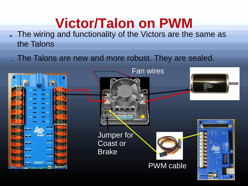
Victor/Talon on PWM The wiring and functionality of the Victors are the same as
the Talons
The Talons are new and more robust. They are sealed.
PWM cable
Fan wires
Jumper for Coast or Brake

VEX Motor Wiring
Uses 6VDC from Digital Sidecar so jumper must be installed.
Jumper
(-) closest to edge, 6VDC on center pin, signal on most inboard pin

Wireless Bridge
`
12V to 5VDC
Power
Converter
DAP-1522 LinkSys Bridge
Ethernet cable

Ethernet Camera
DAP-1522 LinkSys Bridge
Ethernet cable
Axis 206 Camera

Acknowledgements/References Team 358 has an excellent web document with many of the same topics
covered in this presentation
http://team358.org/files/programming/ControlSystem2009-
/components.php
Section 4, “The Robot”, Rules 34 - 74 for the 2013 FRC game
FRC Data Sheets on
Power Distribution Board
Digital Sidecar
Analog Breakout Board
Solenoid Breakout Board
Jag (Black) Getting Started Manual from
http://www.ti.com/lit/ug/spmu131b/spmu131b.pdf