freezer service manual - helmer scientific | medical ... service and maintenance manual i.series ®...
TRANSCRIPT

Freezer Service and Maintenance Manual
i.Series® and Horizon Series™
360144-D/E
Laboratory i.SeriesiLF120, iLF125
Horizon SeriesHLF120, HLF125
Plasma Storagei.SeriesiPF120, iPF125
Horizon SeriesHPF120, HPF125
360370/B
Document Updates The document is furnished for information use only, is subject to change without notice and should not be construed as a commitment by Helmer Scientific. Helmer Scientific assumes no responsibility or liability for any errors or inaccuracies that may appear in the informational content contained in this material. For the purpose of clarity, Helmer Scientific considers only the most recent revision of this document to be valid.
Notices and DisclaimersConfidential / Proprietary NoticesUse of any portion(s) of this document to copy, translate, disassemble or decompile, or create or attempt to create by reverse engineering or otherwise replicate the information from Helmer Scientific products is expressly prohibited.
Copyright and TrademarkCopyright © 2018 Helmer, Inc. Helmer®, i.Series®, i.C³®, Horizon Series™, and Rel.i™ are registered trademarks or trademarks of Helmer, Inc. in the United States of America. All other trademarks and registered trademarks are the property of their respective owners. Helmer, Inc., doing business as (DBA) Helmer Scientific and Helmer.
DisclaimerThis manual is intended as a guide to provide the operator with necessary instructions on the proper use and maintenance of certain Helmer Scientific products.Any failure to follow the instructions as described could result in impaired product function, injury to the operator or others, or void applicable product warranties. Helmer Scientific accepts no responsibility for liability resulting from improper use or maintenance of its products.The screenshots and component images appearing in this guide are provided for illustrative purposes only, and may vary slightly from the actual software screens and/or product components.
Helmer Scientific14400 Bergen BoulevardNoblesville, IN 46060 USAwww.helmerinc.comISO 13485:2003 CERTIFIED Part No. 360370/B
Document HistoryRevision Date CO Supersession Revision DescriptionA 4 OCT 2016 12140 n/a Initial release (all units with serial numbers 2035000 and greater).
B 28 FEB 2018 13358 B supersedes A
Updated amperage dataUpdated parts tables to include Heatcraft Fan Motor for 230V unitsUpdated schematics to include change to Access Control KeypadUpdated Emergo address
* Date submitted for Change Order review. Actual release date may vary.

Helmer Scientific i.Series® and Horizon Series™ Freezer - Upright Service and Maintenance Manual
360370/B ii
Contents1 About this Manual . . . . . . . . . . . . . . . . . . . . . . . . . . . . . . . . . . . . . . . . . . . . . . . . . . . . . . . . . . . . . . . . . . . . . . . . . . . . . . . . . . . . . . . . . . . . . . . . 4
1.1 Safety Precautions and Symbols . . . . . . . . . . . . . . . . . . . . . . . . . . . . . . . . . . . . . . . . . . . . . . . . . . . . . . . . . . . . . . . . . . . . . . . . . . . . . . . 41.2 Model and Input Power . . . . . . . . . . . . . . . . . . . . . . . . . . . . . . . . . . . . . . . . . . . . . . . . . . . . . . . . . . . . . . . . . . . . . . . . . . . . . . . . . . . . . . . 51.3 Product Labels . . . . . . . . . . . . . . . . . . . . . . . . . . . . . . . . . . . . . . . . . . . . . . . . . . . . . . . . . . . . . . . . . . . . . . . . . . . . . . . . . . . . . . . . . . . . . 5
2 InstallationandConfiguration . . . . . . . . . . . . . . . . . . . . . . . . . . . . . . . . . . . . . . . . . . . . . . . . . . . . . . . . . . . . . . . . . . . . . . . . . . . . . . . . . . . . . . 62.1 Location Requirements . . . . . . . . . . . . . . . . . . . . . . . . . . . . . . . . . . . . . . . . . . . . . . . . . . . . . . . . . . . . . . . . . . . . . . . . . . . . . . . . . . . . . . . 62.2 Placement and Leveling . . . . . . . . . . . . . . . . . . . . . . . . . . . . . . . . . . . . . . . . . . . . . . . . . . . . . . . . . . . . . . . . . . . . . . . . . . . . . . . . . . . . . . 62.3 Connect Back-Up Power . . . . . . . . . . . . . . . . . . . . . . . . . . . . . . . . . . . . . . . . . . . . . . . . . . . . . . . . . . . . . . . . . . . . . . . . . . . . . . . . . . . . . . 62.4 Prepare for Monitoring . . . . . . . . . . . . . . . . . . . . . . . . . . . . . . . . . . . . . . . . . . . . . . . . . . . . . . . . . . . . . . . . . . . . . . . . . . . . . . . . . . . . . . . 72.5 ConfigureStorage . . . . . . . . . . . . . . . . . . . . . . . . . . . . . . . . . . . . . . . . . . . . . . . . . . . . . . . . . . . . . . . . . . . . . . . . . . . . . . . . . . . . . . . . . . . 92.6 Optional Adapter Kits for Medication Dispensing Locks . . . . . . . . . . . . . . . . . . . . . . . . . . . . . . . . . . . . . . . . . . . . . . . . . . . . . . . . . . . . . 10
3 Controls . . . . . . . . . . . . . . . . . . . . . . . . . . . . . . . . . . . . . . . . . . . . . . . . . . . . . . . . . . . . . . . . . . . . . . . . . . . . . . . . . . . . . . . . . . . . . . . . . . . . . . . .113.1 Home Screen and Screensaver . . . . . . . . . . . . . . . . . . . . . . . . . . . . . . . . . . . . . . . . . . . . . . . . . . . . . . . . . . . . . . . . . . . . . . . . . . . . . . . .113.2 Home Screen Functions . . . . . . . . . . . . . . . . . . . . . . . . . . . . . . . . . . . . . . . . . . . . . . . . . . . . . . . . . . . . . . . . . . . . . . . . . . . . . . . . . . . . . .113.3 Alarm Reference . . . . . . . . . . . . . . . . . . . . . . . . . . . . . . . . . . . . . . . . . . . . . . . . . . . . . . . . . . . . . . . . . . . . . . . . . . . . . . . . . . . . . . . . . . . .113.4 Settings . . . . . . . . . . . . . . . . . . . . . . . . . . . . . . . . . . . . . . . . . . . . . . . . . . . . . . . . . . . . . . . . . . . . . . . . . . . . . . . . . . . . . . . . . . . . . . . . . . 123.5 Sensor Calibration . . . . . . . . . . . . . . . . . . . . . . . . . . . . . . . . . . . . . . . . . . . . . . . . . . . . . . . . . . . . . . . . . . . . . . . . . . . . . . . . . . . . . . . . . . 16
4 Maintenance . . . . . . . . . . . . . . . . . . . . . . . . . . . . . . . . . . . . . . . . . . . . . . . . . . . . . . . . . . . . . . . . . . . . . . . . . . . . . . . . . . . . . . . . . . . . . . . . . . . . 204.1 Alarm Tests . . . . . . . . . . . . . . . . . . . . . . . . . . . . . . . . . . . . . . . . . . . . . . . . . . . . . . . . . . . . . . . . . . . . . . . . . . . . . . . . . . . . . . . . . . . . . . . 214.2 Upgrade System Firmware . . . . . . . . . . . . . . . . . . . . . . . . . . . . . . . . . . . . . . . . . . . . . . . . . . . . . . . . . . . . . . . . . . . . . . . . . . . . . . . . . . . 224.3 Test and Replace Back-up Batteries . . . . . . . . . . . . . . . . . . . . . . . . . . . . . . . . . . . . . . . . . . . . . . . . . . . . . . . . . . . . . . . . . . . . . . . . . . . . 234.4 Check Probe Bottle . . . . . . . . . . . . . . . . . . . . . . . . . . . . . . . . . . . . . . . . . . . . . . . . . . . . . . . . . . . . . . . . . . . . . . . . . . . . . . . . . . . . . . . . . 234.5 Clean Freezer . . . . . . . . . . . . . . . . . . . . . . . . . . . . . . . . . . . . . . . . . . . . . . . . . . . . . . . . . . . . . . . . . . . . . . . . . . . . . . . . . . . . . . . . . . . . . 23
5 Service . . . . . . . . . . . . . . . . . . . . . . . . . . . . . . . . . . . . . . . . . . . . . . . . . . . . . . . . . . . . . . . . . . . . . . . . . . . . . . . . . . . . . . . . . . . . . . . . . . . . . . . . 255.1 Refrigerant . . . . . . . . . . . . . . . . . . . . . . . . . . . . . . . . . . . . . . . . . . . . . . . . . . . . . . . . . . . . . . . . . . . . . . . . . . . . . . . . . . . . . . . . . . . . . . . 255.2 Remove / Replace Unit Cooler Cover . . . . . . . . . . . . . . . . . . . . . . . . . . . . . . . . . . . . . . . . . . . . . . . . . . . . . . . . . . . . . . . . . . . . . . . . . . . 25
6 Troubleshooting . . . . . . . . . . . . . . . . . . . . . . . . . . . . . . . . . . . . . . . . . . . . . . . . . . . . . . . . . . . . . . . . . . . . . . . . . . . . . . . . . . . . . . . . . . . . . . . . 276.1 General Operation Problems . . . . . . . . . . . . . . . . . . . . . . . . . . . . . . . . . . . . . . . . . . . . . . . . . . . . . . . . . . . . . . . . . . . . . . . . . . . . . . . . . 27
7 i.Series® Parts . . . . . . . . . . . . . . . . . . . . . . . . . . . . . . . . . . . . . . . . . . . . . . . . . . . . . . . . . . . . . . . . . . . . . . . . . . . . . . . . . . . . . . . . . . . . . . . . . . 31
8 Schematics . . . . . . . . . . . . . . . . . . . . . . . . . . . . . . . . . . . . . . . . . . . . . . . . . . . . . . . . . . . . . . . . . . . . . . . . . . . . . . . . . . . . . . . . . . . . . . . . . . . . 348.1 iPFandiLFModels;120and125Configurations . . . . . . . . . . . . . . . . . . . . . . . . . . . . . . . . . . . . . . . . . . . . . . . . . . . . . . . . . . . . . . . . . . 34
9 InstallationandConfiguration . . . . . . . . . . . . . . . . . . . . . . . . . . . . . . . . . . . . . . . . . . . . . . . . . . . . . . . . . . . . . . . . . . . . . . . . . . . . . . . . . . . . . 369.1 Location Requirements . . . . . . . . . . . . . . . . . . . . . . . . . . . . . . . . . . . . . . . . . . . . . . . . . . . . . . . . . . . . . . . . . . . . . . . . . . . . . . . . . . . . . . 369.2 Placement and Leveling . . . . . . . . . . . . . . . . . . . . . . . . . . . . . . . . . . . . . . . . . . . . . . . . . . . . . . . . . . . . . . . . . . . . . . . . . . . . . . . . . . . . . 369.3 Connect Back-up Power . . . . . . . . . . . . . . . . . . . . . . . . . . . . . . . . . . . . . . . . . . . . . . . . . . . . . . . . . . . . . . . . . . . . . . . . . . . . . . . . . . . . . 369.4 Prepare for Monitoring . . . . . . . . . . . . . . . . . . . . . . . . . . . . . . . . . . . . . . . . . . . . . . . . . . . . . . . . . . . . . . . . . . . . . . . . . . . . . . . . . . . . . . 379.5 ConfigureStorage . . . . . . . . . . . . . . . . . . . . . . . . . . . . . . . . . . . . . . . . . . . . . . . . . . . . . . . . . . . . . . . . . . . . . . . . . . . . . . . . . . . . . . . . . . 399.6 Optional Adapter Kits for Medication Dispensing Locks . . . . . . . . . . . . . . . . . . . . . . . . . . . . . . . . . . . . . . . . . . . . . . . . . . . . . . . . . . . . . 40
10 Controls . . . . . . . . . . . . . . . . . . . . . . . . . . . . . . . . . . . . . . . . . . . . . . . . . . . . . . . . . . . . . . . . . . . . . . . . . . . . . . . . . . . . . . . . . . . . . . . . . . . . . . . 4110.1 Monitor and Control Interface . . . . . . . . . . . . . . . . . . . . . . . . . . . . . . . . . . . . . . . . . . . . . . . . . . . . . . . . . . . . . . . . . . . . . . . . . . . . . . . . . 4110.2 Alarm Reference . . . . . . . . . . . . . . . . . . . . . . . . . . . . . . . . . . . . . . . . . . . . . . . . . . . . . . . . . . . . . . . . . . . . . . . . . . . . . . . . . . . . . . . . . . . 4210.3 Settings . . . . . . . . . . . . . . . . . . . . . . . . . . . . . . . . . . . . . . . . . . . . . . . . . . . . . . . . . . . . . . . . . . . . . . . . . . . . . . . . . . . . . . . . . . . . . . . . . . 43
11 Maintenance . . . . . . . . . . . . . . . . . . . . . . . . . . . . . . . . . . . . . . . . . . . . . . . . . . . . . . . . . . . . . . . . . . . . . . . . . . . . . . . . . . . . . . . . . . . . . . . . . . . . 4611.1 Alarm Tests . . . . . . . . . . . . . . . . . . . . . . . . . . . . . . . . . . . . . . . . . . . . . . . . . . . . . . . . . . . . . . . . . . . . . . . . . . . . . . . . . . . . . . . . . . . . . . . 47

Helmer Scientific i.Series® and Horizon Series™ Freezer - Upright Service and Maintenance Manual
360370/B iii
11.2 Test and Replace Back-up Batteries . . . . . . . . . . . . . . . . . . . . . . . . . . . . . . . . . . . . . . . . . . . . . . . . . . . . . . . . . . . . . . . . . . . . . . . . . . . . 4711.3 Check Probe Bottle . . . . . . . . . . . . . . . . . . . . . . . . . . . . . . . . . . . . . . . . . . . . . . . . . . . . . . . . . . . . . . . . . . . . . . . . . . . . . . . . . . . . . . . . . 4811.4 Clean the Freezer . . . . . . . . . . . . . . . . . . . . . . . . . . . . . . . . . . . . . . . . . . . . . . . . . . . . . . . . . . . . . . . . . . . . . . . . . . . . . . . . . . . . . . . . . . 48
12 Service . . . . . . . . . . . . . . . . . . . . . . . . . . . . . . . . . . . . . . . . . . . . . . . . . . . . . . . . . . . . . . . . . . . . . . . . . . . . . . . . . . . . . . . . . . . . . . . . . . . . . . . . 4912.1 Refrigerant . . . . . . . . . . . . . . . . . . . . . . . . . . . . . . . . . . . . . . . . . . . . . . . . . . . . . . . . . . . . . . . . . . . . . . . . . . . . . . . . . . . . . . . . . . . . . . . 4912.2 Remove / Replace Unit Cooler Cover . . . . . . . . . . . . . . . . . . . . . . . . . . . . . . . . . . . . . . . . . . . . . . . . . . . . . . . . . . . . . . . . . . . . . . . . . . . 49
13 Troubleshooting . . . . . . . . . . . . . . . . . . . . . . . . . . . . . . . . . . . . . . . . . . . . . . . . . . . . . . . . . . . . . . . . . . . . . . . . . . . . . . . . . . . . . . . . . . . . . . . . 5113.1 General Operation Problems . . . . . . . . . . . . . . . . . . . . . . . . . . . . . . . . . . . . . . . . . . . . . . . . . . . . . . . . . . . . . . . . . . . . . . . . . . . . . . . . . 5113.2 Chamber Temperature Problems . . . . . . . . . . . . . . . . . . . . . . . . . . . . . . . . . . . . . . . . . . . . . . . . . . . . . . . . . . . . . . . . . . . . . . . . . . . . . . 5113.3 Alarm Activation Problems . . . . . . . . . . . . . . . . . . . . . . . . . . . . . . . . . . . . . . . . . . . . . . . . . . . . . . . . . . . . . . . . . . . . . . . . . . . . . . . . . . . 5313.4 Condensation and Icing Problems . . . . . . . . . . . . . . . . . . . . . . . . . . . . . . . . . . . . . . . . . . . . . . . . . . . . . . . . . . . . . . . . . . . . . . . . . . . . . 53
14 Horizon Series™ Parts . . . . . . . . . . . . . . . . . . . . . . . . . . . . . . . . . . . . . . . . . . . . . . . . . . . . . . . . . . . . . . . . . . . . . . . . . . . . . . . . . . . . . . . . . . . 55
15 Schematics . . . . . . . . . . . . . . . . . . . . . . . . . . . . . . . . . . . . . . . . . . . . . . . . . . . . . . . . . . . . . . . . . . . . . . . . . . . . . . . . . . . . . . . . . . . . . . . . . . . . 5815.1 HPFandHLFModels;120and125ConfigurationswithoutAccessControl . . . . . . . . . . . . . . . . . . . . . . . . . . . . . . . . . . . . . . . . . . . . . 5815.2 HPFandHLFModels;120and125ConfigurationswithAccessControl . . . . . . . . . . . . . . . . . . . . . . . . . . . . . . . . . . . . . . . . . . . . . . . . 59
Appendix A: Compliance . . . . . . . . . . . . . . . . . . . . . . . . . . . . . . . . . . . . . . . . . . . . . . . . . . . . . . . . . . . . . . . . . . . . . . . . . . . . . . . . . . . . . . . . . . . . . 60
Appendix B: Warranty . . . . . . . . . . . . . . . . . . . . . . . . . . . . . . . . . . . . . . . . . . . . . . . . . . . . . . . . . . . . . . . . . . . . . . . . . . . . . . . . . . . . . . . . . . . . . . . . 61

Helmer Scientific i.Series® and Horizon Series™ Freezer - Upright Service and Maintenance Manual
360370/B 4
1 About this ManualThis manual provides information on how to use i.Series® and Horizon Series™ laboratory and plasma storage freezers. It is intended for use by end users of the freezer and authorized service technicians.Models are indicated by a distinguishing model number that corresponds to the series, type, number of doors, and capacity of the freezer. For example, “iLF125” refers to an i.Series Laboratory Freezer with 1 door and a capacity of 25 cu ft, while “HLF125” refers to a Horizon Series Laboratory Freezer with 1 door and a capacity of 25 cu ft.Generic references are used throughout this manual to group models that contain similar features. For example, “125 models” refers to all models of that size (iPF125, HPF125, iLF125, HLF125). This manual covers all upright freezers, which may be identifiedsingly,bytheirsize,orbytheirrespective“Series.”
1.1 Safety Precautions and Symbols
Symbols found in this document
The following symbols are used in this manual to emphasize certain details for the user:
Task Indicates procedures which need to be followed.
Note Provides useful information regarding a procedure or operating technique when using Helmer Scientificproducts.
NOTICE Advises the user against initiating an action or creating a situation which could result in damage to equipment; person injury is unlikely.
CAUTION Advises the user against initiating an action or creating a situation which could result in damage to equipment or impair the quality of the products or cause minor injury.WARNING Advises the user against initiating an action or creating a situation which could result in damage to equipment and serious personal injury to a patient or the user.
Manufacturer
Authorized representative in the European Community
Symbols found on the units
The following symbols may be found on the freezer or freezer packaging:
CE Mark (European units only) Earth / ground terminal
Caution: Risk of damage to equipment or danger to operator
Protective earth / ground terminal
Caution: Hot surface Compliance with Restriction of Hazardous Substances Directive
Caution: Shock / electrical hazard Product falls under the scope of the WEEE (Waste Electrical and Electronic Equipment) directive.
Caution: Unlock all casters
EC REP

Helmer Scientific i.Series® and Horizon Series™ Freezer - Upright Service and Maintenance Manual
360370/B 5
Avoiding Injury
♦ Review safety instructions before installing, using, or maintaining the equipment. ♦ Do not open multiple, loaded drawers at the same time. ♦ Do not move a unit whose load exceeds 900 lbs (408 kg). ♦ Before moving unit, ensure casters are unlocked and free of debris. ♦ Never physically restrict any moving component. ♦ Avoid removing electrical service panels and access panels unless so instructed. ♦ Use manufacturer supplied power cords only. ♦ UsingtheequipmentinamannernotspecifiedbyHelmerScientificmayimpairtheprotectionprovidedbytheequipment. ♦ Ensure biological materials are stored safely, in accordance with all applicable organizational, regulatory, and legal
requirements.
CAUTIONDecontaminatepartspriortosendingforserviceorrepair.ContactHelmerScientificoryourdistributorfordecontamination instructions and a Return Authorization Number.
1.2 Model and Input Power
NoteService information varies depending on the model and power requirements.
Table 1. Model and Input Power
Model Voltage FrequencyCurrent
Draw
120
115V 60 Hz 8.5 A230V 50 Hz 3.8 A230V 60 Hz 4.3 A
125
115V 60 Hz 8.5 A230V 50 Hz 3.8 A230V 60 Hz 4.3 A
* Amperage values are subject to change. Refer to the product specification label on your unit for current values.
1.3 Product LabelsThisinformationappearsontheproductspecificationlabel,locatedontherearofthefreezerbelowtheelectricalbox.Themodelalso appears on a label located in the chamber on the upper side of the right wall.
NoteInformationcontainedinthespecificationlabelvariesdependingonthemodelandpowerrequirements.
Sample Specification label.
Label Description
A Model (REF)
B Serial number
C Power requirementsC
A
B

Helmer Scientific i.Series® and Horizon Series™ Freezer - Upright Service and Maintenance Manual
360370/B 6
i.Series Information
2 InstallationandConfiguration2.1 Location Requirements ♦ Groundedoutletmeetingtheelectricalrequirementslistedontheproductspecificationlabel. ♦ Clear of direct sunlight, high temperature sources, and heating and air conditioning vents. ♦ Minimum 3” (76 mm) of space behind unit. ♦ Meetslimitsspecifiedforambienttemperature(15°Cto32°C)andrelativehumidity.
2.2 Placement and Leveling
CAUTIONTo prevent tipping, ensure the casters are unlocked, leveling feet (if installed) are lifted, and the doors are closed before moving the freezer.
1. Move freezer into place. Lock casters if installed.2. Ensure freezer is level.
Note• Helmer recommends the use of leveling feet.• Leveling feet (if installed) must be adjusted to provide unit cooler drainage.
2.3 Connect Back-Up PowerThe monitoring system and chart recorder each have a back-up battery system enabling a period of continuous operation if power is lost.Battery life varies by manufacturer as well as voltage level remaining. Providing full power is available and no battery-related alarms are active, back-up power for the monitoring system is available for up to 20 hours. Providing full power is available, back-up power for the optional Access Control system is available for up to 2.5 hours.
CAUTIONBefore installing or replacing batteries, switch AC power and back-up battery switch OFF. Disconnect freezer from AC power.
Notes• The optional Access Control system uses the monitoring system back-up battery for back-up power in the event of power failure.• The monitoring system will start on back-up battery power alone. If the freezer was not previously connected to AC power and the back-up battery is switched on, the monitoring system will begin running on back-up power.• If AC power is lost, the monitoring system will automatically disable some features to prolong back-up battery power. Data collection will continue until back-up power is depleted.
Monitoring system back-up battery.
i.Series Information

Helmer Scientific i.Series® and Horizon Series™ Freezer - Upright Service and Maintenance Manual
360370/B 7
2.4 Prepare for MonitoringThe battery is located on the top of the freezer and is switched off for shipping. Switch battery on to provide monitoring system with back-up power in the event of AC power failure.
Temperature Probes
Notes• Temperature probes are fragile; handle with care.• The number and location of probes varies by model• Remote probes may also be introduced through the existing top port and immersed in existing probe bottles.
The probe bottle along with a container of propylene glycol have been provided with this unit. The propylene glycol is mixed with watertocreateasolutionwhichsimulatestheproductstoredinthefreezer.Theproductsimulationsolutiontemperaturereflectsthe product’s temperature during normal operation.The probe bottle should contain 4 oz. (120 mL) of product simulation solution at a 1:1 ratio of water to propylene glycol.
Probe bottle with temperature probes Top access port
Fill Probe Bottle1. Remove all probes from bottle and remove bottle from bracket.2. Removecapandfillwith4oz(120mL)ofproductsimulationsolution.3. Install cap and place bottle in bracket.4. Replace probes, immersing at least 2” (50 mm) in solution.
Install Additional Probe Through Top Port1. Peel back putty to expose port.2. Insert probe through port into chamber.3. Insert probe into bottle.4. Replace putty, ensuring a tight seal.
Chart Recorder (if included)
Notes• If chart recorder has been operating on battery power, the battery should be replaced to ensure the back-up source has proper charge.• For complete information, refer to the Temperature Chart Recorder Operation and Service Manual included with the unit.
The chart recorder has a back-up battery system, enabling a period of continuous operation if power is lost. Battery life varies by manufacturer as well as voltage level remaining. Providing full power is available, back-up power for the temperature chart recorder is available for up to 14 hours.
Prior to use:Place probe in bottle with primary monitor probe.
i.Series Information

Helmer Scientific i.Series® and Horizon Series™ Freezer - Upright Service and Maintenance Manual
360370/B 8
Set Up and OperationAccess chart recorder by pressing and releasing the door.
Install BatteryConnect the leads to the battery to provide back-up power to the chart recorder.
Install / Replace Chart Paper
Notes• For accurate temperature reading, ensure the current time is aligned with the time line groove when chart knob is tightened• Contact Helmer Customer Service to reorder chart paper; part number 220419 (52 sheets).
Chart recorder stylus and time line groove
1. Press and hold Cbutton.Whenstylusbeginstomoveleft,releasebutton.TheLEDflashestoindicatecurrent temperature range.2. When stylus stops moving, remove chart knob then move knob up and away.3. Place chart paper on chart recorder.4. Gently lift stylus and rotate paper so current time line corresponds to time line groove.5. Hold chart paper and reinstall chart knob is fully tightened. (Failure to fully tighten the knob can result in paper slipping and losing time.)6. Press and hold C button. When stylus begins to move right, release button. 7. Confirmstylusismarkingonpaperandstopsatthecorrecttemperature.8. Calibrate chart recorder to match primary temperature if needed and close recorder door.
i.Series Information

Helmer Scientific i.Series® and Horizon Series™ Freezer - Upright Service and Maintenance Manual
360370/B 9
External Monitoring DevicesThe remote alarm interface is a relay switch with three terminals: ♦ Common (COM) ♦ Normally Open (NO) ♦ Normally Closed (NC)
Terminals are dry contacts and do not supply voltage. Interface circuit is either normally open or normally closed, depending on terminals used.Requirements for your alarm system determine which alarm wires must connect to terminals.
CAUTION• The interface on the remote alarm monitoring system is intended for connection to the end user’s central alarm system(s) that uses normally-open or normally-closed dry contacts.• If an external power supply exceeding 30 V (RMS) or 60 V (DC) is connected to the remote alarm monitoring system’s circuit, the remote alarm will not function properly and may cause damage to the control board or result in injury to the user.
The terminal on the remote alarm interface have the following maximum load capacity: ♦ 0.5 A at 30 V (RMS) ♦ 1.0 A at 24 V (DC)
Connect to Remote Alarm Interface1. On the electrical box, locate the remote alarm terminals.2. Connect remote alarm wires to appropriate terminals, according to requirements for your alarm system.3. Use a cable tie to relieve strain on alarm wires (as necessary).
2.5 ConfigureStorage
CAUTION• Before moving drawers, ensure they are completely empty for safe lifting.• Maximum basket, drawer, or shelf load is 100 lbs (46 kg).
NoteBefore moving storage components, protect stored items in freezer from extended exposure to adverse temperature.
Product Loading GuidelinesWhen loading your freezer, take care to observe the following guidelines:
♦ Never load freezer beyond capacity. ♦ Always store items within shelves, drawers or baskets. ♦ Temperatureuniformityismaintainedbyaircirculation,whichcouldbeimpededifunitisoverfilled,particularlyatthetop
or back. Ensure proper clearance is provided below the fan.
NoteProductsstackedagainstbackwallmayobstructairflowandaffectperformanceofunit.
Drawers and Baskets Remove Drawer or Basket1. Pull drawer or basket out until it stops.2. Tilt the front of the drawer or basket upward.3. Pull drawer or basket free of the slides.
Install a Drawer or Basket1. Align end guides on drawer or basket with the slides.2. Gently push drawer or basket into chamber until it stops.3. Pull drawer or basket out until it stops; check for smooth operation.
i.Series Information

Helmer Scientific i.Series® and Horizon Series™ Freezer - Upright Service and Maintenance Manual
360370/B 10
Move Drawer Slides1. Using a screwdriver, remove front bracket retainers.2. Tap front brackets upward to disengage standards.3. Remove slides from standards.4. Insert slides into standard at appropriate height.5. Tap front brackets downward to engage standards.6. Using a screwdriver, install front bracket retainers.
Shelves Remove Shelf1. With one hand, lift front edge of the shelf from the front brackets.2. With the other hand, reach under the shelf and bump rear edge of the shelf upward to disengage rear brackets.
Install Shelf1. Insert shelf into chamber, placing it on brackets.2. Gently bump rear edge of the shelf downward to engage brackets.3. Pulling shelf forward gently; shelf should not disengage from rear brackets.
Move Shelf Brackets1. Using a screwdriver, remove front bracket retainers.2. Tap front brackets upward to disengage standards.3. Remove front brackets from standards.4. Insert front brackets into standard at appropriate height.5. Tap front brackets downward to engage standards.6. Using a screwdriver, install front bracket retainers.
2.6 Optional Adapter Kits for Medication Dispensing LocksContact Helmer Technical Service or your distributor for service documentation pertaining to medication dispensing locks.
i.Series Information

Helmer Scientific i.Series® and Horizon Series™ Freezer - Upright Service and Maintenance Manual
360370/B 11
3 Controlsi.Series models are equipped with the i.C3 monitoring and control system. The i.C3 system combines temperature control and monitoring into a single user interface.
NotePlease refer to the i.C3 User Guide for complete information regarding the i.C3 User Interface.
3.1 Home Screen and ScreensaverThe Home Screen is the default screen and is displayed when:
♦ The Home icon is touched from any other screen. ♦ There is no interaction for two minutes on most screens other than those used to enter a password.
Home Screen Screensaver
3.2 Home Screen Functions Note
Refer to the i.C3 User Guide for options available on all i.C3 screens.
♦ View current interior cabinet temperature readings ♦ Viewmin/maxtemperatureoccuranceforaspecifiedtimeperiod ♦ View the current system time and date ♦ Accessanyofthefivehomescreenapplications(touchi.C3 APPS for additional applications) ♦ View information about current alarm events ♦ View whether the monitoring system is running on battery power ♦ Mute audible alarms ♦ View a graph of the chamber temperature ♦ View unit ID ♦ Shortcut to Event Log
3.3 Alarm ReferenceIf an alarm condition is met, an alarm activates. Some alarms are visual only; others are visual and audible. Some alarms are sent through the remote alarm interface. The table indicates if an alarm is audible (A), visual (V), or sent through the remote alarm interface (R).
Table 2. i.Series Alarm Reference
Alarm Alarm Type Alarm Alarm Type
High Temperature A, V, R Low Battery V
Low Temperature A, V, R No Battery A, V, R
Compressor Temperature A, V, R Probe Failure A, V, R
Door Open (Time) A, V, R Communication Failure A, V, R
Power Failure A, V, R
i.Series Information

Helmer Scientific i.Series® and Horizon Series™ Freezer - Upright Service and Maintenance Manual
360370/B 12
3.4 Settings
> Through the i.C³ monitoring and control system, current settings may be viewed and changed. To view settings, touch i.C³ APPS, Settings. Use a touch-drag motion to scroll up or down to display additional settings.
Settings screens
Note• IftheSettingsscreenispasswordprotectedenterappropriatepassword.Ifviewingsettingsforthefirsttime,enter factory default password of “1234”.• Default values for general settings, alarm settings, and display settings are available in the i.C³ User Guide.• Changing temperature settings affects the operation of the freezer. Do not change settings unless instructed in product documentation or by Helmer Technical Service.
Thei.C³temperaturemonitorandcontrollerisprogrammedatthefactory.Tochangeasetting,firstentertheSettingsscreen,thenthe setting. The method for accessing the Settings mode for each setting varies.
i.Series Information

Helmer Scientific i.Series® and Horizon Series™ Freezer - Upright Service and Maintenance Manual
360370/B 13
Device Control SettingsDevice control settings are programmed at the factory. Setpoints can be viewed and changed through the i.C³ monitoring and control system. To view temperature setpoints, touch i.C³ APPS, Settings, Device Control Settings.
Device Control Settings screen
Table 3. Setpoints
SettingModel120 / 125
Temperature Setpoint -30.0°C
Hysteresis Setpoint 2.0°C
Delay on Start-Up 2 minutes
Duty Cycle During Control Probe Error 100%
Temperature SetpointThe setpoint is the temperature at which the unit operates.
Notes• IftheSettingsscreenispasswordprotectedenterappropriatepassword.Ifviewingforthefirsttime,enterthefactory default password of “1234”.• Changethesetpointifyourorganizationrequiresachambertemperatureotherthan-30.0°C.
Change Temperature Setpoint1. Touch i.C³ APPS, i.C³ Settings.2. Enter the Settings password.3. Touch minus (–) or plus (+) on the Temperature Setpoint spin box.
Hysteresis SetpointHysteresis is the allowable temperature variance on each side of the freezer setpoint.
Delay on Start-UpCompressor start-up is delayed to allow the i.C3monitoringandcontrolsystemtostartfirst.
Duty Cycle During Control Probe ErrorThe duty cycle is the percentage of time the compressor will run in the event of a temperature control probe failure.
NoteHysteresis, Delay on Start-up and Duty Cycle During Control Probe Error are factory-preset and should not be changed unless directed by Helmer Technical Service.
i.Series Information

Helmer Scientific i.Series® and Horizon Series™ Freezer - Upright Service and Maintenance Manual
360370/B 14
Defrost Settings
Note• Depending on the high temperature alarm setpoint and the actual temperature increase during the defrost cycle, frequent door openings may trigger repeated high temperature alarms.• There must be a minimum of four hours between defrost cycles.
Defrosteventsmaybescheduledtooccuratspecifictimes.Adefrosteventcanbetriggeredondemandwithoutaffectingaprogrammed defrosting schedule. The number of programmed defrost events is dependent on environmental conditions and the frequency of usage. The recommended number of daily defrost cycles is three to four, at even intervals. Defrost events should take place when the freezer door is opened infrequently.The i.C³ monitoring and control system can perform a maximum of four defrost cycles per day.
Schedule or Start a Defrost Event1. Touch i.C³ APPS, Defrost Settings.2. Toggle the ON/OFF button to schedule the defrost event(s), or Toggle the Start/Stop button. The Defrost icon will appear for the duration of the defrost cycle.3. Touch the corresponding Time spin box to set the starting time for each defrost event slected.
Table 4. Default Defrost Cycles
Defrost Event On/Off Default Time
1 On 12:15 AM
2 On 8:00 AM
3 On 4:00 PM
4 Off 6:00 PM
UserConfigurableAlarmSettingsThe following alarm settings may be changed by the operator. The setpoint for temperature alarms may be changed (where applicable), as well as the time delay between when the alarm condition commences and when the visual and audible alarms are initiated.
Table5.UserConfigurableAlarms
Setting Description Default Value Default Time DelayPrimary Monitor Probe High Temp High temperature at which alarm condition occurs -20°C 0 minutes
Primary Monitor Probe Low Temp Low temperature at which alarm condition occurs -35°C 0 minutes
Compressor High Temp High temperature at which alarm condition occurs 50°C 0 minutes
Power Failure Time after power failure occurs until alarm sounds 1 minutes
Probe Failure Time after probe failure occurs until alarm sounds 0 minutes
Door Open (Time) Time door remains open until alarm sounds 3 minutes
Secondary Monitor Probe High Temp(if installed)
High temperature at which alarm condition occurs -20°C 0 minutes
Secondary Monitor Probe Low Temp Low temperature at which alarm condition occurs -35°C 0 minutes
Low Battery Triggered after approximately 18 hours of use Not adjustable
i.Series Information

Helmer Scientific i.Series® and Horizon Series™ Freezer - Upright Service and Maintenance Manual
360370/B 15
Alarm settings screens
Change an Alarm Setting1. Touch i.C3 APPS, Settings.2. Enter the Settings password (default password is “1234”).3. Scroll down and touch Alarm Settings.4. Touch the minus (-) or plus (+) on the corresponding Setpoint spin box to change an alarm setpoint.5. Touch the minus (-) or plus (+) on the corresponding Time Delay spin box to change the time delay duration6. Touch Home to exit the Alarm Settings screen.
Non-ConfigurableAlarmsThefollowingalarmsindicateoperationalconditionswhichrequiretheattentionoftheoperatororaqualifiedservicetechnician.
Table6.Non-ConfigurableAlarm
Alarm DescriptionLow Battery Rechargeable battery voltage is low
Communication Failure Communication Failure 1• Triggered if communication is lost between i.C3 display board and control board• Unit will continue to run with previously saved settings• Screen will not display temperature changes or alarm conditions• i.C3 system will continue to reset until connection is re-establishedCommunication Failure 2• Triggered if communication is lost between i.C3 display board and internal system memory• Unit will continue to run with previously saved settingsCommunication Failure 3• Triggered if the database is corrupted• The database is archived and a new database is automatically created• Unit will continue to run with previously saved settings
i.Series Information

Helmer Scientific i.Series® and Horizon Series™ Freezer - Upright Service and Maintenance Manual
360370/B 16
3.5 Sensor Calibration
>
Sensor calibration values are programmed at the factory. Calibration values can be viewed and changed through the i.C³ monitoring and control system. To view calibration settings, touch i.C³ APPS, Settings and scroll down to Sensor Calibration.
Settings screen
Sensor Calibration screens
Notes• IftheSettingsscreenispasswordprotected,entertheappropriatepassword.Ifviewingsettingsforthefirsttime,enter factory default password of “1234”.• After one hour of no interaction, the Home screen or Temperature Graph screensaver (if enabled) is displayed.• The Compressor Probe Offset and Evaporator Defrost Probe Offset settings are factory-preset and should not be changed unless directed by Helmer Technical Service.
i.Series Information

Helmer Scientific i.Series® and Horizon Series™ Freezer - Upright Service and Maintenance Manual
360370/B 17
Primary Monitor ProbeVerify primary monitor probe is reading chamber temperature correctly by comparing probe reading to the temperature measured by calibrated reference thermometer. If the probe is not reading correctly, change the value displayed on the monitor.Thefactorydefaultsettingfortheprimarymonitorprobeis-30.0°C.
Notes• Ensure product simulation bottle is full of solution.• Probe in the bottle is connected to the monitoring system and senses chamber temperature. This probe activates the temperature alarms, but does not affect freezer setpoint.
Calibrate primary monitor probe1. Remove monitor probe from the probe bottle.2. Unscrew the cap from the bottle.3. Attach the thermometer to the monitor probe, and place them in the bottle. The probe and thermometer should be immersed at least 2” (50 mm).4. Close the door and allow the chamber temperature to stabilize for 10 minutes.5. Observe and note the thermometer temperature.6. Touch, i.C³ APPS, Settings, Sensor Calibration.7. Touch (-) or plus (+) on the corresponding spin box to increase or decrease the value to match the measured value. The message “New Setting Saved” appears next to the spin box.8. Remove thermometer from probe.9. Replacebottlecap,ensuringatightfit.10. Place probe in bottle, immersing at least 2” (50 mm).
Control ProbeThe temperature controller senses unit cooler temperature through the control probe in the unit cooler. The unit cooler temperature typically varies from the chamber temperature, so an offset value is used by the control system to compensate for the difference.The temperature controller adjusts chamber temperature around the freezer setpoint by activating the compressor when the control probe registers above the setpoint based on the hysteresis value.
Determine control probe offset
NOTICEThemonitortemperaturemustbeverifiedandaccuratepriortoadjustingtheControlProbeOffset.
1. View and record the freezer setpoint.2. Allow the unit to run with calibrated monitor temperature for several compressor cycles, and record the average monitor temperature .3. View and record the current Control Probe Offset value.4. Subtract the freezer setpoint from the average monitor temperature and record the difference.5. Add the current Control Probe Offset value to the recorded difference determined in the previous step to establish the new Control Probe Offset value.
EXAMPLE 1 EXAMPLE 2
Freezer temperature setpoint is -30.0 Freezer temperature setpoint is -30.0
Average monitor temperature is -29.2 Average monitor temperature is -31.2
Current Control Offset is 0.3 Current Control Offset is 0.3
Subtract: -29.2 - (-30.0) = 0.8 (difference between average temperature and setpoint) Subtract: -31.2 - (-30.0) = -1.2 (difference between average temperature and setpoint)
Add 0.3 + 0.8 = 1.1; new Control Offset value Add 0.3 + (-1.2 ) = -0.9; new Control Offset value
i.Series Information

Helmer Scientific i.Series® and Horizon Series™ Freezer - Upright Service and Maintenance Manual
360370/B 18
Enter the new offset value1. Touch i.C³ APPS, Settings.2. Enter the Settings password.3. Touch Sensor Calibration.4. Touch the minus (-) or plus (+) on the Control Probe Offset spin box.
♦ Raise the offset value to lower chamber temperature; lower the offset value to raise chamber temperature.5. Touch Home to return to home screen.
Compressor and Evaporator ProbeThe compressor and evaporator temperature probes have been factory-calibrated. Changing the calibration settings is not typically necessary and should not be performed unless directed by Helmer Technical Service.
Factory Default SettingsSettings listed below may be simultaneously returned to factory default values.
NoteThe factory default settings may not be the same as the settings that were factory-calibrated before the freezer was shipped.
Table 7. Restored Settings
Setting Restored Value
Home Screen Application Icons i.C³ APPS, Settings, Temperature Graph, Temperature Alarm Test, Information Logs
Display Brightness High (3 symbols)
Password (for Settings screen) 1234
Sounds On
Alarm Volume 9
Alarm Tone 3
Temperature Calibration Values Not affected (values previously entered during setup)
Unit ID Not affected (previously selected during setup)
Date Format MM/DD/YYYY
Day Not affected (maintained in real-time clock)
Month
Year
Time Format 12-hour
Minute Not affected (maintained in real-time clock)
Hour
AM/PM
Language Not affected (language previously selected during setup)
Temperature Units °C
Password Protection (for Settings screen) On
Temperature Graph Screensaver On
Access Control (optional) as Home Page On
High Temperature Alarm Setpoint -20.0°C
High Temperature Alarm Time Delay 0 minutes
Low Temperature Alarm Setpoint -35.0°C
Low Temperature Alarm Time Delay 0 minutes
Power Failure Alarm Time Delay 1 minute
Probe Failure Alarm Time Delay 0 minutes
Door Open (Time) Alarm Time Delay 3 minutes
i.Series Information

Helmer Scientific i.Series® and Horizon Series™ Freezer - Upright Service and Maintenance Manual
360370/B 19
Setting Restored Value
Compressor Temperature Alarm Setpoint 50.0°C
Compressor Temperature Alarm Time Delay 0 minutes
Chamber Setpoint -30.0°C
Chamber Hysteresis 2.0°C
Delay on Start-Up 2 minutes
Control Relay Probe Failure Duty Cycle 100%
Defrost Event #1 On/Off On
Defrost Event #1 Start Time 12:15 AM
Defrost Event #2 On/Off On
Defrost Event #2 Start Time 8:00 AM
Defrost Event #3 On/Off On
Defrost Event #3 Start Time 4:00 PM
Defrost Event #4 On/Off Off
Defrost Event #4 Start Time 6:00 PM
Defrost Safety Operation Time 15 minutes
Restore Settings1. Touch the Settings icon. 2. Scroll down and touch the Restore Factory Settingsbutton.TheRestoreFactorySettingsconfirmationboxappears.3. Touch toconfirm,or to cancel.
i.Series Information

Helmer Scientific i.Series® and Horizon Series™ Freezer - Upright Service and Maintenance Manual
360370/B 20
4 MaintenanceMaintenance tasks should be completed according to the schedule below.
CAUTIONMaintenance should only be performed by trained refrigeration technicians.
Notes• The preventive maintenance schedule provides recommended minimum requirements. Regulations or physical conditions at your organization may require maintenance items be performed more frequently, or only by designated service personnel.• Before performing maintenance, protect items in freezer from extended exposure to adverse temperature.• Allow freezer temperature to stabilize at setpoint after performing service or after extended door opening.
Table 9. i.Series Preventive Maintenance Schedule
TaskFrequency
Quarterly Annually 2 years As Needed
Test the high and low temperature alarms.
Test the power failure alarm.
Test the door alarm (as required by your organization’s protocols).
Check the temperature calibration on the monitor and change it if necessary.
Replace the monitoring system back-up battery.
Checkthelevelofthesolutionintheprobebottles.Refillorreplacesolutionifnecessary.
Examine the probe bottles and clean or replace if necessary.
Clean the condenser grill.
Clean the door gaskets, interior, and exterior of the freezer.
Inspect ground strap (Units prior to serial number 2022299)
Electrical compartment• Inspect electrical components and wiring terminals in the electrical box for discoloration. Contact Helmer Technical Service if any discoloration is found.• Inspect all wiring for terminals for secure connection. Tighten wiring terminal connections as necessary.
Models with Chart RecordersCheck the backup battery for the chart recorder after an extended power failure and change it if necessary, or change the battery if it has been in service for one year. Refer to the Temperature Chart Recorder Operation and Service Manual.
NOTICEClean the condenser grill on a quarterly basis.
NoteDuring a power failure, the back-up battery provides power to the monitoring system, power failure alarm, and optional Access Control. If the back-up battery is not functioning, the power failure alarm will not be activated and the battery should be replaced.
i.Series Information
Helmer Scientific i.Series® and Horizon Series™ Freezer - Upright Service and Maintenance Manual
360370/B 21
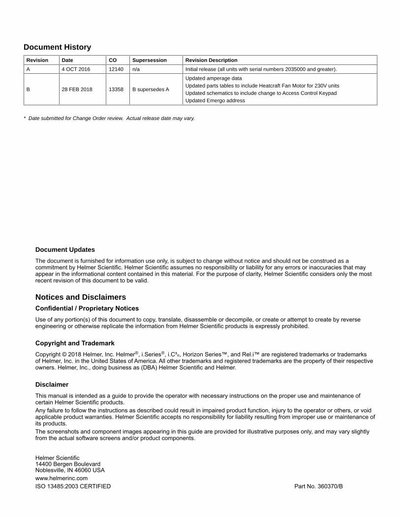
4.1 Alarm Tests
> Test alarms to ensure they are working correctly. The freezer has alarms for chamber temperature, compressor temperature, door open (time), power failure, low battery, and power failure. To initiate alarm tests, touch i.C3 APPS, Temperature Alarm Test.
Automatic Chamber Temperature Alarm Test
Temperature Alarm Test screen
Notes• A test can be aborted by touching Cancel Test at any time.• Testtakeslessthanfiveminutes.• If the temperature alarm test does not automatically complete within two minutes, restart the i.C³ monitoring system.
When performing an automatic temperature alarm test, the Peltier device heats or cools the monitor probe until the high or low alarm setpoint is reached. An event is added to the Event Log to indicate a temperature alarm was activated. The Alarm Test icon is displayed on the Temperature Graph to indicate the temperature alarm was test-induced.
Test the low alarm1. Identify current setting for low alarm setpoint.2. Touch i.C³ APPS, Temperature Alarm Test.3. Touch Low Alarm Test.4. “Peltier Test probe cooling” message appears.5. When displayed temperature reaches the alarm setpoint, temperature reading turns red.6. When completed, “Test Complete” appears.7. Touch i.C³ APPS, Information Logs, Event Log. Touch the event to view event details.8. Observe the temperature at the time of the low temperature alarm event. Compare this to the alarm setpoint.
Test the high alarm1. Identify current setting for high alarm setpoint.2. Touch Home, i.C³ APPS, Temperature Alarm Test.3. Touch High Alarm Test.4. “Peltier Test probe warming” message appears.5. When displayed temperature reaches the alarm setpoint, the temperature reading turns red.6. When completed, “Test Complete” appears.7. Touch i.C³ APPS, Information Logs, Event Log. Touch the event to view event details.8. Observe the temperature at the time of the high temperature alarm event. Compare this to the alarm setpoint.
i.Series Information

Helmer Scientific i.Series® and Horizon Series™ Freezer - Upright Service and Maintenance Manual
360370/B 22
Cancel alarm test1. Touch the Cancel Test icon to end the alarm test. “Test Stopped” is displayed in the Test Status section of the display.
NoteWhen cancelling an automatic test, the message indicating the test is in progress clears immediately. If a setpoint was reached before the test was cancelled, the alarm activates and clears as described earlier.
Manual Chamber Alarm Test
NOTICE• Perform the low alarm test before the high alarm test to control the temperature more closely and complete the testing more quickly.• Before testing alarms, protect items in freezer from extended exposure to adverse temperature.• Temperature probes are fragile; handle with care.
Test the high alarm1. Identify setting for high alarm setpoint.2. Place the glass of product simulation solution in the freezer.3. When the product simulation solution has stabilized at the chamber temperature, remove the solution from the freezer.4. Remove the monitor probe from the probe bottle and insert into the product simulation solution.5. Observe the temperature on the i.C³ display at which the high temperature alarm sounds.6. Compare the temperature at which the alarm sounds to the high alarm setpoint.7. Remove probe from product simulation solution.8. Place monitor probe in probe bottle, immersing it at least 2” (50 mm).
Power Failure Alarm Test
NoteDuring a power failure, the power failure alarm sounds and the battery provides power to the monitoring system.
Test power failure alarm1. Change Power Failure delay setting to 0 minutes by touching Settings, Alarm Settings then touching + or – on the Power Failure spin box to change the value to 0.2. Switch AC ON/OFF switch OFF. Power failure alarm will activate immediately.3. Switch AC ON/OFF switch ON. Power failure alarm will clear and audible alarm will cease.4. Change Power Failure time delay to the original setting.
Door Open Alarm Test
Test door open alarm1. Change Door Open (Time) delay setting to 0 minutes by touching Home, Settings, Alarm Settings, then touching the minus (-) or plus (+) on the Door Open (Time) spin box to change the value to 0.2. Open door. Alarm will activate immediately.3. Close door. Alarm will clear and audible alarm will cease.4. Change the Door Open (Time) setting to the original setting.
4.2 Upgrade System FirmwareHelmermayoccasionallyissueupdatesforthei.C³firmware.Followupgradeinstructionsincludedwiththefirmwareupdate.
i.Series Information
Helmer Scientific i.Series® and Horizon Series™ Freezer - Upright Service and Maintenance Manual
360370/B 23
4.3 Test and Replace Back-up Batteriesi.C3 Monitoring System Back-up BatteryOn all i.C³ screens, the Battery icon will appear in the header bar when the system is running on battery power and the screen brightness will automatically be reduced. The monitoring system will automatically disable some features to extend battery life.
Check the i.C3 Monitoring System back-up battery1. Turn the AC On/OFF switch OFF. The screen should continue to display information with reduced brightness and the battery icon will appear on the screen. 2. If the display is blank, replace the battery.3. Switch AC ON/OFF switch ON.
NoteUseabatterywhichmeetsmanufacturer’sspecifications.
Access Control Back-up BatteryDuring an AC power failure, the Access Control back-up battery provides back-up power to power the magnetic Access Control lock.
Test the Access Control back-up battery1. Ensure monitoring system / Access Control battery key switch is switched ON.2. Switch AC ON/OFF switch OFF.3. Attempt to open the cabinet door.4. If the door remains locked, the battery is functional.5. If the door does not remain locked, replace the battery.6. Switch AC ON/OFF switch ON.
Chart Recorder Back-up Battery (if included)Refer to 360076-1 Temperature Chart Recorder Operation and Service Manual.
4.4 Check Probe BottleRemove the probe bottle from the bracket and inspect for cracks. Replace the bottle if necessary.Ensure the probe bottle has approximately 4 oz. (120 mL) of product simulation solution at a 1:1 ratio of water to propylene glycol. The propylene glycol is used to create a solution which simulates the product stored in the freezer. The product simulation solutiontemperaturereflectstheproduct’stemperatureduringnormaloperation.Failuretofillthebottlemaypreventthechambertemperature from stabilizing that the temperature setpoint. The probe should be immersed at least 2” (50 mm).
4.5 Clean FreezerCabinet ExteriorClean exterior surfaces with soft cotton cloth and non-abrasive liquid cleaner.
Cabinet InteriorClean painted surfaces with mild detergent. Clean stainless steel surfaces with a general-purpose laboratory cleaner suitable for stainless steel.
Condenser Grill
CAUTIONDisconnect freezer from AC power when cleaning the condenser grill.
In environments where the freezer is exposed to excessive lint or dust, the condenser grill may require cleaning more frequently than stated in preventive maintenance schedule.Clean the condenser grill using a soft brush and a vacuum cleaner.
i.Series Information

Helmer Scientific i.Series® and Horizon Series™ Freezer - Upright Service and Maintenance Manual
360370/B 24
Door GasketsClean with soft cloth and mild soap and water solution.
Probe BottlesCleanandrefillprobebottles1. Remove probe from bottle.2. Remove bottle from bracket.3. Clean bottle with water-bleach solution.4. Fill bottle with 4 oz (120 mL) of product simulation solution.5. Cap bottle tightly to minimize evaporation.6. Place bottle in bracket.7. Replace probe, immersing at least 2” (50 mm).
i.C³® TouchscreenClean touchscreen with a soft, dry cotton cloth.
i.Series Information

Helmer Scientific i.Series® and Horizon Series™ Freezer - Upright Service and Maintenance Manual
360370/B 25
5 Service5.1 Refrigerant
CAUTION• Review all safety instructions prior to recharging refrigerant. Refer to Section 1.1 (Safety). • Maintenance should only be performed by trained refrigeration technicians.
Notes• Use only non-CFC R-404A refrigerant.• Pressure readings may vary based on chamber temperature and ambient air temperature.• Normal low side pressures are 2 psi to 4 psi when unit is functioning at standard operating temperatures and measured at the end of the compressor cycle.• Ifarefrigerantleakissuspected,Helmerrecommendsfindingandfixingtheleakpriortorechargingtheunit.
Fullinitialrefrigerantchargevariesbymodelandpowerrequirements,whichcanbefoundontheproductspecificationlabel.
Table 10. Refrigerant Charge
Model Refrigerant Power Requirements Initial Charge
120 / 125 R404A 115 V, 60 Hz 230 V, 50/60 Hz
29.0 oz (822 g)
5.2 Remove / Replace Unit Cooler CoverThe unit cooler must be removed when servicing the control probe, fan motor(s), defrost element, defrost sensors, or coil.
NOTICEIf unit cooler cover is not removed as detailed in this procedure the drain port may be damaged. Improper drainage may result in excessive icing and freezer’s inability to maintain temperature.
Remove unit cooler cover
CAUTIONThe condensate evaporator and water evaporation tray are hot.
1. Switch AC ON/OFF switch OFF. Disconnect the battery.2. On the back of the cabinet, peel the putty back to expose the drain tube and drain heater.3. Verify the heating element is cool. Remove the screws and loosen the pipe straps securing the drain tube to the cabinet.4. Remove the drain heater from the drain tube.5. Removethedraintubebypullingitdownward.Thedraintubeshouldseparatefromthefantubeatthe90°elbow, leaving the fan tube attached to the fan.6. Separate the drain hose inside the cabinet from the unit cooler drain port by gently twisting the drain hose from left to right
A
G
FED
C
B
Label DescriptionA Unit cooler cover
B Drain port
C Drain fan
D Fan tube
E Heater wires
F Heating element
G Drain tube
i.Series Information

Helmer Scientific i.Series® and Horizon Series™ Freezer - Upright Service and Maintenance Manual
360370/B 26
to separate it from the unit cooler drain port.7. Pivot the drain tube and drain hose upward to remove the assembly from the cabinet.8. Remove top drawer, basket, or shelf from the chamber.
NoteUnits without the Cold-Shield panel proceed to Step 10.
9. Loosen three screws securing Cold-Shield panel to the cabinet and slide panel to disengage from screws and remove.10. Using a 5/16” socket wrench, remove the four screws securing the unit cooler cover to the top of the cabinet while supporting the cover with one hand to prevent it from dropping.11. Carefully lower the unit cooler cover to avoid damage to the fan wiring.
Install unit cooler cover1. Verify unit cooler wiring is connected and routed correctly. Wiring should be routed above the copper tube inside the unit cooler. Reconnect wires if they have separated.2. Lift the unit cooler cover into place and attach using four screws. Tighten using a 5/16” socket wrench to secure.3. From the rear of the unit, insert the drain tube through the opening into the cabinet. The drain tube should be aligned with the unit cooler drain spout inside the chamber and the connection to the fan tube at back of the unit.4. Attach the drain tube to the unit cooler drain spout and the fan tube.5. Insert the drain line heater in the drain tube at an upward angle. The black heating element should no longer be visible.6. Replace putty around the drain tube inside the cabinet.7. Reinstall top drawer, basket, or shelf if previously removed.
NoteUnits without the Cold-Shield panel proceed to Step 9.
8. Reinstall Cold-Shield panel and tighten screws to secure.9. Reattach the pipe straps to secure the drain tube to the cabinet.10. Switch AC ON/OFF switch ON. Reconnect the battery.11. Touch Mute to disable the high temperature alarm while freezer reaches operating temperature
i.Series Information

Helmer Scientific i.Series® and Horizon Series™ Freezer - Upright Service and Maintenance Manual
360370/B 27
6 Troubleshooting
CAUTIONReview all safety instructions prior to troubleshooting. Refer to Section 1.1.
6.1 General Operation ProblemsProblem Possible Cause Action
A drawer does not slide easily.
Ice buildup in the drawer slides. Pullthedraweroutandconfirmtheslidesarefreeofice.De-iceifnecessary.
Debris in the drawer slides. Pullthedraweroutandconfirmtheslidesarefreeofdebris.Cleanifnecessary.
Drawer is misaligned or not level. Confirmbothslidesforthedraweraremountedatthesameheight.
Drawer slide is faulty. Confirmtheslideisoperatingcorrectly.Replaceifnecessary.
The door does not open easily.
Door handle is not aligned. Properly align door handle.
Debris in the hinges. Confirmthehingesarefreeofdebris.Cleanthehingesifnecessary.
Door hinges are not lubricated. Using a general-purpose grease, lubricate the pivots in the hinges.
Hinge cam is faulty. Confirmthehingecamisnotdamaged.Replacethecamifnecessary.
The monitor display is hard to read.
Screen brightness is set too low. Change the screen brightness.
The display/monitor is not responding.
Digital electronics are locked because of an interruption in power.
Reset the monitoring system
“Probe Failure” is displayed on the monitor.
Probe wiring is an open circuit Check the continuity of the probe wiring and connections. Secure the connections if necessary
Confirmtheprobeisprovidingresistanceintherangeof86Ωto110Ω.Replace the probe if necessary.
Test CP board circuitry by removing the probe connector fromthe board and placingjumperacrossjumperpins.Displayshouldshow4°C+/-2°C.ContactHelmer Technical Service.
i.Series Information

Helmer Scientific i.Series® and Horizon Series™ Freezer - Upright Service and Maintenance Manual
360370/B 28
6.2 Chamber Temperature ProblemsProblem Possible Cause Action
The chamber temperature displayed is higher or lower than the actual temperature.
Probe bottle is empty, or the amount of solution is too low.
Checkthelevelofproductsimulationsolutioninthebottle.Cleanandrefillthebottle if necessary.
Solution in probe bottle is frozen. Refillthebottlewithnewsolution.
Primary monitor probe(s) is not calibrated.
Check the chamber temperature calibration. Change the calibration if necessary.
Digital electronics are locked due to an interruption in power.
Reset the monitoring system.
Connections for the primary monitor probe are loose.
Check primary monitor probe connections. Secure connections if necessary.
A component is faulty or internal connections are loose.
Contact Helmer Technical Service.
Chamber temperature meets an alarm condition, but appropriate temperature alarm is not active.
Temperature alarm setpoint was changed.
Check the current setpoints for the temperature alarms. Change the setpoints if necessary.
Component is faulty or connections are loose
Contact Helmer Technical Service.
The compressor runs continuously.
Freezer setpoint is set too low. Confirmthesetpointissetwithintheoperatingrangeandchangeitifnecessary.
Control probe is not reading correctly.
Check control probe reading; adjust offset if necessary.
Check probe connections at CP board.
Test CP board circuitry by placing jumper across suspected failed probe. Displayshouldshow4°C+/-2°C.ContactHelmerTechnicalService.
Solid state relay is faulty. Confirmtherelayisoperatingcorrectly.Replacetherelayifnecessary.
The chamber temperature does not stabilize at the freezer setpoint
Circulation in the chamber is not adequate.
Checkifthereareanyitemsthatmayobstructairflowandremovethemifnecessary.
Unit cooler fan is not running. Check the voltage to the fan when door switch is activated. Replace the fan motor or door switch if necessary.
Condenser grill is dirty. Check the condenser grill. Clean it if necessary.
Ambient air temperature around the freezer is too high.
Confirmfreezerlocationmeetsrequirements.Refertotheoperationmanual.
Condensing unit fan is not running. Check the condensing unit fan connections. Replace the fan motor if necessary.
Evaporator is covered with ice and is not exchanging heat.
Initiate a freezer defrost cycle.
Control probe is not reading correctly.
Check control probe reading; adjust offset if necessary.
Check probe connections at CP board.
Test CP board circuitry by placing jumper across suspected failed probe. Displayshouldshow4°C+/-2°C.ContactHelmerTechnicalService.
Refrigerant level is too low. Check the refrigeration lines for leaks and repair them if necessary. Check the refrigerant level. Recharge the refrigerant if necessary.
A component is faulty or internal connections are loose.
Contact Helmer Technical Service.
6.3 Alarm Activation ProblemsProblem Possible Cause Action
The freezer is in an alarm condition, but alarms are not audible.
Audible alarms are muted. Verifythataudiblealarmsarenotmuted.Iftimeremainingisgreaterthanfiveminutes,changeMUTEtimervaluetofiveminutesandwaituntiltimerresets.
Alarm system component is faulty or internal connections are loose.
Confirmthecircuitboardandlineconnectionsarefunctioningcorrectly.Contact Helmer Technical Service.
Speaker is faulty. Replace the speaker.
The freezer meets an alarm condition, but the appropriate alarm is not active.
Alarm setpoint was changed. Check the current setpoints for the alarms.
A component is faulty or internal connections are loose.
Contact Helmer Technical Service.
i.Series Information

Helmer Scientific i.Series® and Horizon Series™ Freezer - Upright Service and Maintenance Manual
360370/B 29
Problem Possible Cause Action
The High Temperature alarm activates when the door is opened, then clears shortly after the door is closed.
Probe bottle is empty. Check the level of product simulation solutioninthebottle.Cleanandrefillbottle if necessary.
High temperature alarm setpoint is set too low.
Check the setpoint. Change the setpoint if necessary.
Unit cooler fan continues to run while the door is open.
Test the door switch and unit cooler fan connections. Secure the connections if necessary. Replace the door switch or fan motor if necessary.
A component is faulty or internal connections are loose.
Contact Helmer Technical Service.
The freezer is connected to power, but the AC Power Failure alarm is active.
ON/OFF AC power switch is OFF. Turn the ON/OFF AC power switch to the ON position.
Outlet connection is faulty. Verify power at the outlet. Repair the original outlet or connect to a different outlet if necessary.
Power cord is faulty. Confirmthepowercordisconnectedsecurely.Securethepowercordifnecessary.
Circuit breaker is tripped. Reset or replace the circuit breaker.
A component is faulty or internal connections are loose.
Contact Helmer Technical Service.
The Door Open alarm is activating sporadically.
Door is not closing completely. Confirmthehingecamsarenotdamaged.Replacethecamsifnecessary.
Doors are closing but not sealing completely.
Ensure door switch is being activated by the door switch plate. Adjust as needed.
Door switch is faulty. Replace the door switch.
Door Open Timeout is set to zero, causing alarm to activate immediately when door is opened.
Check the time delay for the Door Open alarm. Change the time delay if necessary.
Temperature monitor/controller board is faulty.
Contact Helmer Technical Service.
All alarms are activating sporadically.
Alarm system component is faulty or internal connections are loose..
Confirmthecircuitboardandlineconnectionsarefunctioningcorrectly.Contact Helmer Technical Service.
The condenser alarm is active.
Condenserfinsaredirty. Clean as necessary, or contact Helmer Technical Service or your distributor.
Condenser fan motor is faulty. Replace the condenser fan motor.
Compressor is overheating due to ambient air temperature around freezer is too high.
Confirmthefreezeriscorrectlylocated.Refertotheoperationmanual.
Condenser alarm setpoint is too low.
Confirmthealarmsetpointisattheappropriatevalue.
Condenser probe is not calibrated.
Confirmthecondenserprobeisreadingcorrectly.Calibratetheprobeifnecessary.
A component is faulty or internal connections are loose.
Contact Helmer Technical Service.
An alarm activated, but the temperature recorded at activation does not match the alarm setpoint.
Monitor settings are not calibrated. Confirmthemonitorprobeisreadingcorrectly.Calibratetheprobeifnecessary.
Temperature changed slightly around the time of activation.
No action necessary.
The “No Battery” alarm is activating sporadically.
Battery voltage level on the back-up battery for the monitoring system is low.
Replace the backup battery for the monitoring system.
The “High Temperature” alarm is activating sporadically.
Primary monitor probe is not immersed in the product simulation solution.
Confirmtheprobebottleisfullofsolution,andtheprobeisplacedinthebottlecorrectly.
Upper monitor probe is not calibrated.
Confirmtheuppermonitorprobeisreadingcorrectly.Calibratetheprobeifnecessary.
A component is faulty or internal connections are loose.
Contact Helmer Technical Service.
i.Series Information

Helmer Scientific i.Series® and Horizon Series™ Freezer - Upright Service and Maintenance Manual
360370/B 30
6.4 Testing ProblemsProblem Possible Cause Action
The automatic temperature tests do not work.
High Alarm setpoint is set significantlyhigherthanthedefault value, or the Low Alarm setpointissetsignificantlylowerthan the default value.
Confirmthealarmsetpointsaresetattheexpectedorcorrectvalues.
Test the temperature alarms manually.
Connections for the monitor probe are loose.
Test the monitor probe connections. Secure the connections if necessary.
Monitor probe is faulty. Test the monitor probe. Replace the probe if necessary.
A component is faulty or internal connections are loose.
Contact Helmer Technical Service.
6.5 Condensation and Icing ProblemsProblem Possible Cause Action
There is excessive water in the water evaporation tray.
Humid air is entering the chamber Confirmthefreezerislevel,andthedoorisaligned,closingtightly,andsealingcorrectly. Correct issues as necessary.
Heater in the water evaporation tray is faulty.
Confirmtheheaterishotandisdrawingthecorrectcurrent(approximately0.21 A to 0.35 A for the 230V model, 0.36 to 0.56 for the 115V model). Replace the heater if necessary.
There is excessive ice in the chamber
Humid air is entering the chamber.
Confirmthefreezerislevel,andthedoorisaligned,closingtightly,andsealingcorrectly. Correct issues as necessary.
Unit cooler drain line is damaged or restricted.
Confirmtheunitcoolerdrainlineisfreeofdebrisandisnotrestricted.Removedebris if necessary.
Connection between the unit cooler and the drain line is loose.
Confirmtheconnectionissecure.Tightentheconnectionifnecessary.
There is excessive moisture on the door.
Humid air is entering the chamber.
Confirmthefreezerislevel,andthedoorisaligned,closingtightly,andsealingcorrectly.
Relative humidity around freezer is too high.
Confirmfreezerlocationmeetsrequirements.
After a defrost cycle, no waterflowsintothewaterevaporation tray.
Drain line is plugged. Confirmthedraintubeisfreeofdebris.Removedebrisifnecessary.
Drain line heater is faulty. Confirmthedrainlineheateriswarmtothetouch.ContactHelmerTechnicalService to resolve issues as necessary.
Defrost heater on the evaporator in the unit cooler is faulty.
Check for ice buildup on the evaporator by looking through the fan grill with aflashlight.Ifthereissignificanticebuildupinsideorbehindtheunitcooler,initiate a defrost cycle of the freezer.
Confirmdefrostheaterishotandisdrawingtheappropriatecurrentduringadefrost event (approximately 3.3 A to 5.5 A for the 230V model, 7.8 A to 10.7 A for the 115V model).
Replace the defrost heater if necessary.
i.Series Information

Helmer Scientific i.Series® and Horizon Series™ Freezer - Upright Service and Maintenance Manual
360370/B 31
7 i.Series® Parts
Note• Before replacing parts, protect items in freezer from extended exposure to adverse temperature.• Allow freezer temperature to stabilize at setpoint after replacing parts or after extended door opening.• The i.C3 display assembly is sensitive to static electricity and can be damaged by electrostatic discharge. Use proper ESD precautions when handling the display assembly.• Although the touchscreen and display board may be replaced independently of the i.C3 display assembly, Helmer recommends replacing the complete assembly.
Letter Description Part # Letter Description Part #A Bezel
* = without chart recorder door800069-2 F Chart recorder door assembly 800070-1
400998-2* G Chart paper (52 sheets) 220419
B Door handle 220426 H Chart recorder back-up battery 120218
C Magnetic lock 800138-1 I Display assembly (includes touchscreen display board, interface cable, speaker) 800042-1
D Caster (swivel with brake) 220467
E Temperature chart recorder (standard on plasma freezer model, optional on laboratory freezer model) 800084-1
Not shown USB / Power cable for i.Center display 800010-1
B
I
HGF
E
D
A
C
J
i.Series Information

Helmer Scientific i.Series® and Horizon Series™ Freezer - Upright Service and Maintenance Manual
360370/B 32
Letter Description Model Part # Volts Letter Description Model Part # VoltsA Unit Cooler Assembly - 800870-1 115 Not
ShownDrawer slide assembly (left side) 120 400541-4 -
- 800871-1 230 125 400541-2 -
B Unit Cooler Fan Motor (Heatcraft / Peerless) - 800872-1 115 Roll-out basket assembly (optional includes basket, 2 slides, hardware)
120 400890-1 -
- 800950-1 230 125 400890-2 -
- 800873-1 230 Roll-out basket slide assembly(right side)
120 400541-3 -
C Unit Cooler Fan Blade (Heatcraft / Peerless) - 800874-1 115/230 125 400541-1 -
- 800875-1 230 Roll-out basket slide assembly(left side)
120 400541-4 -
D Unit Cooler Fan Guard (Heatcraft / Peerless) - 800876-1 115/230 125 400541-2 -
- 800877-1 230 Drawer slide wheel - 320815-1 -
E Unit Cooler Drain Pan (Heatcraft / Peerless) - 800878-1 115/230 Half shelf (includes hardware) - 400413-1 -
- 800879-1 230 O Secondary monitor probe - 800037-1 -
F Control Probe - 800048-1 - P Door switch - 120380 -
G Defrost Heater (Heatcraft / Peerless) - 800880-1 115 Q Mullion heater (behind strike plates) - 800883-1 115
- 800881-1 230 - 800884-1 230
- 800882-1 230 Not Shown
Strike plate replacement kit - 400687-1 -
H Defrost heater high limit thermostat - 800014-1 - R Upper hinge assembly * = left ** = right
(includes pin and bracket)
- 400960-2* -
I TXV (expansion) valve - 800110-1 - - 400960-1** -
J Chart recorder probe - 800024-1 - S Upper hinge bearing - 220541 -
K Primary monitor probe - 800038-1 - T Door gasket - 320726-1 -
L Probe bottle and propylene glycol kit - 400922-2 - U Door bumper - 220441 -
M Full Shelf (includes hardware) 120 400414-1 - V Lower hinge cam (quantity 2) - 320742-1 -
125 400414-2 - W Lower hinge bearing - 220375 -
N Drawer assembly (includes drawer, 2 slides, hardware)
120 400584-2 - X Door stop - 320763-1 -
125 400584-1 - Y Ground strap (units prior to SN 2022299) - 120688 -Not
ShownDrawer slide assembly (right side) 120 400541-3 - Z Lower hinge bracket * = left ** = right - 400377-2* -
125 400541-1 - - 400377-1**
M
H
G
I
i.Series Information
B
L
KJ
FED
A
C
ZYXWV
U
T
SR
P
N
Q
O

Helmer Scientific i.Series® and Horizon Series™ Freezer - Upright Service and Maintenance Manual
360370/B 33
CAUTION• Disconnect the freezer from AC power before opening the electrical box.• Do not remove the cover from the condensate evaporator tray.
NoteThe i.C³ control board is sensitive to static electricity and can be damaged by electrostatic discharge. Use proper ESD precautions when handling the board.
Letter Description Part # Volts Letter Description Part # Volts HzA i.C³ control board (blue board) 800034-4 - N Battery back-up switch 120202 - -
i.C³ control board (green board) 800034-3 - O Main power switch 120478 - -
B Power supply board 800035-1 - P Circuit breaker, 12 A 120220 230 -
C Solid state relay 120426 - Q Back-up battery key switch (optional Access Control) 401220-1 - -
D Powerlinefilter 120400 - R Monitoring system battery (optional Access Control) 120628 - -
E Drain Line Fan 800885-1 115 S Condensing Unit 800866-1 115 60
800886-1 230 800867-2 230 50
F Drain Line Heater 800887-1 115 800867-1 230 60
800279-1 230 T Condenser Fan Motor 800868-1 115 60
G Drain Line - - 800869-2 230 50
H Condensate Evaporator Assembly(includes condensate evaporator, tray and cover)
400790-1 115 800869-1 230 60
400790-2 230 U Compressor Electrical Components 800864-1 115 60
I Power Cable* = European models
800001-1 115 800865-2 230 50
800002-1 230 800865-1 230 60
800003-1* 230 V Solenoid valve 220547 - -
J Remote alarm contacts - - W Solenoid coil 800863-1 115 -
K RJ-45 Ethernet port 800008-1 - 800017-1 230 -
L USB port 120633 - Not Shown
Condenser probe 800039-1 - -
M RS-232 serial port (optional) - -
i.Series Information
A
BIH
GFE
D
C
T
S
RQ
P
O
N
M
KL
J
T
U
V W

Helmer Scientific i.Series® and Horizon Series™ Freezer - Upright Service and Maintenance Manual
360370/B 34
8 Schematics8.1 iPFandiLFModels;120and125Configurations
THESE DRAWINGS AND SPECIFICATIONS ARE THE SOLE PROPERTY OF HELMER INC. AND SHALL NOT BE REPRODUCED ORUSED AS THE BASIS FOR MANUFACTURE OR SALES OF APPARATUS WITHOUT THE APPROVAL OF HELMER INC.
L2 IN GND
L2 OUT
L1 IN
L1 OUT
MAINPOWERSWITCH
CIRCUITBREAKERS
POWER CORD
MAIN POWER
230V~ / 50 Hz208/230V~ / 60 Hz
DC
POW
ER SU
PPLY
GROUND TERMINAL
CO
MPR
ESSOR
1 2 3 5 6 7 8 9 104
Fromi.C3, J44, Pin 1
RFI Filter
1
2
3
4
5
6
7
8
9
10
11
12
i.C3 Power PCBA
COMPRESSOR
12
11
6
10
9
7
8
5
4
3
2
1
i.C3 Power PCBA
Solid State Relay #1
L1 T
ERM
INAL
STR
IPL2
/NEU
TRAL
TER
MIN
AL S
TRIP
i.C3, J18, Pin 1
Mullion Heater(U)
Drain Line Heater(T)
CondensateEvaporator
Fromi.C3, J43, Pin 2
UNIT COOLERFAN
3 X N
H 4 F
(F) UNIT COOLER
DEFROST HEATERLIMIT THERMOSTAT
JUNCTION BOX
DEFROSTHEATER
(S)
(R)SNUBBERCIRCUIT
EXTERNAL DRAIN FAN(Q)
4(C)
(B)
(E)(D)
(J)
(A)
12S039/C
115V~ / 60 Hz
*230V ONLY
CP BO
ARD
Fromi.C3, J42, Pin 2
i.Series Information

Helmer Scientific i.Series® and Horizon Series™ Freezer - Upright Service and Maintenance Manual
360370/B 35
THESE DRAWINGS AND SPECIFICATIONS ARE THE SOLE PROPERTY OF HELMER INC. AND SHALL NOT BE REPRODUCED ORUSED AS THE BASIS FOR MANUFACTURE OR SALES OF APPARATUS WITHOUT THE APPROVAL OF HELMER INC.
L1-2
123+ 4-
3-28VDC
DOOR SWITCH
Primary Monitor Probe
CondensorDischarge Probe
Control Probe
L2-4
L1-4
CO
MN
.O.
L1-5
To U
nit C
oole
r Fan
i.C3 Power PCBA
5
Secondary Monitor Probe
To E
vapo
rato
r Def
rost
Hea
ter
To C
onde
nsat
e E
vapo
rato
r
CHARTRECORDER
*Option
9V
- +
CHARTRECORDER
BATTERYBACKUP
Evap DefrostControl Probe
N/L2
L1
RS232
(M)
(iK)
Speaker
(iL)
(L)COMPRESSOR
SSR
*Option
(iT)
USB Port
SD Memory Card(iM)
To LCD
LCD Back Light
LCD Touch Screen
Reset
i.C3 LCDw/ Touch Screen
i.C3 Display PCBA
(iD)
(iJ)
(CA)
(CC)
USB Host
COM
NO
NC
Bezel MountComponents
USB Port(iE)
F4
Battery
BYPASS ON
(iQ)
USB Data Cable(iG) Power Cable
(iH)
Ethernet Port(iF)
EXTERIORALARM
CONTACTS
(iL)
CONDENSING UNITFAN MOTOR
(K)
COMPRESSOR(J)L2-2
CONDENSING UNITFAN MOTOR
3
SOLENOID COIL(V)
SOLENOID VALVE(W)
12V
MONITORBATTERYBACKUP
Magnetic LockAccess Control
*Option
(iB)
(AXb)
BATTERY KEY SWITCH*ACCESS CONTROL OPTION
(AXa)
BATTERYSWITCH*STANDARD
(iC)
12S039/C
J46 J45 J44 J43 J42J18
R86
J41
J40
+
J34
J10
J12
J29
J37
J15
J16J17 J19 J20
J21
J4
J6
J8
J36J35
J22
J24
J25
J27
J28
J335 1
J31
G Y
J23
POWER
J30
J5
J13
J11
J9
J7
J3MICRO JTAG
J1
GND
OUT3OUT2OUT1IN2IN1+5V
+5V
SIG
GND
SHLD
TXRX
RS422/485
11
1
1
AN7AN6
BUILD
-- + + 11
1
GNDTXRX
1
1
1
S
1
S
1
S
NO
NC
COM
NC
NO
C
1
1
1
S
B
G
W
R
1
S
B
G
W
R
1
1 -+1
1+
-
-
+
1
BOOTLOAD
PUR
VUSB
1 SBGWR
SSR2SSR1
CHART
RTD4
RTD5
RTD3
RTD2
RTD1
E-LOCKALARM
DIGITAL IO
ANALOG IO
USB PORT 4
USB PORT 3
RS232
COMM.DISPLAY
ETHERNET
POWERDISPLAY
RLY1RLY2RLY3RLY4RLY5
NONONONO
NO
HELMER INC
REV B
NCNCNCNCNC
VIN
COM
SERIAL NUMBER401143-1
CHARTRECORDER
PROBE
(CB)
CHARTRECORDER
*Option
CHARTRECORDER
PROBE9V
- +
CHARTRECORDER
BATTERYBACKUP
(CA)
(CB)(CC)
Serial Number 2045348 and prior
i.Series Information

Helmer Scientific i.Series® and Horizon Series™ Freezer - Upright Service and Maintenance Manual
360370/B 36
Horizon Series™ Information
9 InstallationandConfiguration9.1 Location Requirements ♦ Groundedoutletmeetingtheelectricalrequirementslistedontheproductspecificationlabel. ♦ Clear of direct sunlight, high temperature sources, and heating and air conditioning vents. ♦ Minimum 3” (76 mm) of space behind unit. ♦ Meetslimitsspecifiedforambienttemperature(15°Cto32°C)andrelativehumidity.
9.2 Placement and Leveling
CAUTIONTo prevent tipping, ensure the casters are unlocked, leveling feet (if installed) are lifted, and doors are closed before moving the freezer.
♦ Roll freezer into place and lock casters ♦ Ensure freezer is level.
Notes• Helmer recommends the use of leveling feet.• Leveling feet (if installed) must be adjusted to provide unit cooler drainage.
9.3 Connect Back-up PowerThe monitoring system and chart recorder each have a battery system, enabling a period of continuous operation if power is lost.Battery life varies by manufacturer as well as voltage level remaining. Providing full power is available and no battery-related alarms are active, backup power for the monitoring system is available for up to 20 hours (the Low Battery alarm will activate after approximately 18 hours of battery use). Providing full power is available, backup power for the optional Access Control system is available for up to 2.5 hours.
CAUTION• Before installing or replacing batteries, switch the power and battery OFF. Disconnect the freezer from AC power.• Wheninstallingareplacementbattery,useonlyabatterywhichmeetsthemanufacturer’sspecifications.
Notes• The optional Access Control system uses the monitoring system battery for back-up power, in the event of a power failure.• The monitoring system will start on battery power alone. If the freezer was previously not connected to AC power and the battery is switched on, the monitoring system will begin running on battery power.
The battery is located on the top of the freezer.
Monitoring system back-up battery (supplies power to optional Access Control system).
Horizon Series Inform
ation

Helmer Scientific i.Series® and Horizon Series™ Freezer - Upright Service and Maintenance Manual
360370/B 37
9.4 Prepare for MonitoringThe back-up battery is switched OFF for shipping. Switch the back-up battery switch ON to provide monitoring system with back-up power in the event of AC power failure.
Temperature Probes
Notes• Temperature probes are fragile; handle with care.• The number and location of probes varies by model• Remote probes may also be introduced through existing top ports and immersed in existing probe bottles.
Probe bottle(s) along with propylene glycol have been provided with this unit. The propylene glycol is used to create a solution whichsimulatestheproductstoredinthefreezer.Theproductsimulationsolutiontemperaturereflectstheproduct’stemperatureduring normal operation.Each bottle should contain 4 oz (120 mL) of product simulation solution at a 1:1 ratio of water to propylene glycol.
Probe bottle. Top access port.
Fill Probe Bottle1. Remove all probes from bottle and remove bottle from bracket.2. Removecapandfillwith4oz.(120mL)ofproductsimulationsolution.3. Install cap and place bottle in bracket.4. Replace probes, immersing at least 2” (50 mm) in solution.
Install Additional Probe Through Top Port1. Peel back putty to expose port.2. Insert probe through port into chamber.3. Insert probe into bottle.4. Replace putty, ensuring a tight seal.
Chart Recorder (if included)The chart recorder has a battery system, enabling a period of continuous operation if power is lost. Battery life varies by manufacturer as well as voltage level remaining. Providing full power is available, back-up power for the temperature chart recorder is available for up to 14 hours.
Notes• If chart recorder has been operating on back-up battery power, the battery should be replaced to ensure the back-up source has proper charge.• For complete information, refer to the Temperature Chart Recorder Operation and Service Manual included with this unit.
Prior to use:Place probe in bottle with primary monitor probe
Horizon Series Inform
ation

Helmer Scientific i.Series® and Horizon Series™ Freezer - Upright Service and Maintenance Manual
360370/B 38
Set-up and OperationAccess chart recorder by pulling the door open.
Install BatteryConnect the leads to the battery to provide back-up power to the chart recorder.
Install / Replace Chart Paper
Notes• For accurate temperature reading, ensure the current time is aligned with the time line groove when chart knob is tightened.• Contact Helmer Technical Service to reorder chart paper, part number 220419 (52 sheets)
Chart recorder stylus and time line groove.
1. Press and hold Cbutton.henstylusbeginstomoveleft,releasebutton.TheLEDflashes.2. When stylus stops moving, remove chart knob then move knob up and away.3. Place chart paper on chart recorder.4. Gently lift stylus and rotate paper so current time line corresponds to time line groove.5. Hold chart paper in place while making sure the chart knob is fully tightened. (Failure to fully tighten the knob can result in paper slipping and losing time.).6. Press and hold C button. When stylus begins to move right, release button. 7. Confirmstylusismarkingonpaperandstopsatthecorrecttemperature.8. Calibrate chart recorder to match primary temperature if needed and close recorder door.
Horizon Series Inform
ation

Helmer Scientific i.Series® and Horizon Series™ Freezer - Upright Service and Maintenance Manual
360370/B 39
External Monitoring DevicesThe remote alarm interface is a relay switch with three terminals: ♦ Common (COM) ♦ Normally Open (NO) ♦ Normally Closed (NC)
Terminals are dry contacts and do not supply voltage. Interface circuit is either normally open or normally closed, depending on terminals used.Requirements for your alarm system determine which alarm wires must connect to terminals.
CAUTION• The interface on the remote alarm monitoring system is intended for connection to the end user’s central alarm system(s) that uses normally-open or normally-closed dry contacts.• If an external power supply exceeding 30 V (RMS) or 60 V (DC) is connected to the remote alarm monitoring system’s circuit, the remote alarm will not function properly; may be damaged; or may result in injury to the user
The terminals on the remote alarm interface have the following maximum load capacity: ♦ 0.5 A at 30 V (RMS) ♦ 1.0 A at 24 V (DC)
Connect to Remote Alarm Interface1. On the electrical box, locate the remote alarm terminals.2. Connect remote alarm wires to appropriate terminals, according to requirements for your alarm system.3. Use a cable tie to relieve strain on alarm wires (as necessary).
9.5 ConfigureStorage
CAUTION• Before moving drawers, ensure they are completely empty for safe lifting.• Maximum basket, drawer, or shelf load is 100 lbs (46 kg).
NoteBefore moving storage components, protect stored items in freezer from extended exposure to adverse temperature.
Product Loading GuidelinesWhen loading your freezer, take care to observe the following guidelines: ♦ Never load freezer beyond capacity. ♦ Always store items within shelves, drawers or baskets. ♦ Temperatureuniformityismaintainedbyaircirculation,whichcouldbeimpededifunitisoverfilled,particularlyatthetoporback.
Ensure proper clearance is provided below the fan.
NoteProductsstackedagainstbackwallmayobstructairflowandaffectperformanceofunit.
Drawers and Baskets Remove a drawer or basket1. Pull drawer or basket out until it stops.2. Tilt the front of the drawer or basket upward.3. Pull drawer or basket free of the slides.
Install a drawer or basket1. Align end guides on drawer or basket with the slides.2. Gently push drawer or basket into chamber until it stops.3. Pull drawer or basket out until it stops; check for smooth operation.
Horizon Series Inform
ation
Helmer Scientific i.Series® and Horizon Series™ Freezer - Upright Service and Maintenance Manual
360370/B 40
Move drawer slides1. Using a screwdriver, remove front bracket retainers.2. Tap front brackets upward to disengage standards.3. Remove slides from standards4. Insert slides into standard at appropriate height.5. Tap front brackets downward to engage standards.6. Using a screwdriver, install front bracket retainers.
Shelves Remove a shelf1. With one hand, lift front edge of the shelf from the front brackets.2. With the other hand, reach under the shelf and bump rear edge of the shelf upward to disengage rear brackets.
Install a shelf1. Insert shelf into chamber, placing it on brackets.2. Gently bump rear edge of the shelf downward to engage brackets.3. Pulling shelf forward gently; shelf should not disengage from rear brackets.
Move shelf brackets1. Using a screwdriver, remove front bracket retainers.2. Tap front brackets upward to disengage standards.3. Remove front brackets from standards.4. Insert front brackets into standard at appropriate height.5. Tap front brackets downward to engage standards.6. Using a screwdriver, install front bracket retainers.
9.6 Optional Adapter Kits for Medication Dispensing LocksContact Helmer Technical Service or your distributor for service documentation pertaining to medication dispensing locks.
Horizon Series Inform
ation

Helmer Scientific i.Series® and Horizon Series™ Freezer - Upright Service and Maintenance Manual
360370/B 41
10 ControlsHorizon Series models are equipped with a monitor and optional control system which allows users to view and change current settings.
10.1 Monitor and Control Interface
Table 11. Monitor and Control Indications
Label Description Function
A COOL lamp Indicates the compressor is running.
B Display Displays real-time temperature information, setpoints, and alarms.
C HIGH TEMP lamp Indicates when the freezer is in a high temperature alarm condition. Also indicates the high alarm temperature setpoint is being changed.
D LOW TEMP lamp Indicates when the freezer is in a low temperature alarm condition. Also indicates the low alarm temperature setpoint is being changed.
E DOOR ALARM lamp Indicates when the door is open.
F DOWN ARROW button Decreasesatemperaturesetting.Alsomutestheaudiblealarmforfiveminutes.
G UP ARROW button Increases a temperature setting.
H SEL button Toggles between alarm monitor and control modes.
I SET lamp Indicates when temperature setpoint or alarm setpoint is being changed.
J SET button Allows settings to be selected, prior to changing settings.
K CONTROL lamp Indicates when the reading from the control probe is displayed.
L MONITOR lamp Indicates when the display is showing temperature readings from the monitor probe. Also indicates when alarm setpoints are being changed.
Display Minimum and Maximum Monitor Temperature Recordings
Notes• This feature is standard on Horizon Series™ models with serial numbers of 2015494 or higher. Some exceptions may exist.Forconfirmationonyourunit,pleasecontactHelmerTechnicalService.• Units that do not include the minimum and maximum recording feature will not display .C or .F when entering the program mode. All temperature readings will appear in .C only.• The following steps only apply to the primary monitor probe.
The minimum and maximum recording feature allows the user to view a minimum temperature occurrence and a maximum temperature occurrence within a given period of time. The timer provides a time reference in which those temperatures occurred.
A
LK
J
I
H
GFEDC
B
Horizon Series Inform
ation

Helmer Scientific i.Series® and Horizon Series™ Freezer - Upright Service and Maintenance Manual
360370/B 42
View minimum temperature recording. ♦ Press and hold the Down Arrow button for 1 second and listen for a single beep. ♦ The display will alternate between LOandavalidtemperaturevaluefive(5)timesfollowedbyasinglebeepto
indicate exit back to the temperature display.
View maximum temperature recording. ♦ Press and hold the Up Arrow button for 1 second and listen for a single beep. ♦ The display will alternate between HIandavalidtemperaturevaluefive(5)timesfollowedbyasinglebeeptoindicate
exit back to the temperature display.
View recorded temperature timer.
Notes• The timer denotes the period of time that has elapsed. It does not display the time at which a minimum or maximum temperature occurred.• The maximum period of time the timer can record is 99:59 (99 hours and 59 minutes).
♦ Press and hold either the Up or Down Arrow button for 1 second. or ♦ WhilethedisplayisflashingtheHI or LO value, press and hold the SET button for 1 second. ♦ Thedisplaywillalternatefive(5)timesbetweenCLr and a value representing the number of hours and minutes that
have elapsed since the last recording (example: 12:47 would represent 12 hours and 47 minutes). A single beep will follow to indicate exit back to temperature display.
Clear minimum and maximum temperature recordings. ♦ Press and hold either the Up or Down Arrow button for 1 second. or ♦ WhilethedisplayisflashingtheHI or LO value, press and hold the SET button for 1 second and listen for a single beep. ♦ Whilethedisplayisflashingtheelapsedtimesincelastreset,pressandholdtheSET button for 2 seconds. CLr will
be displayed followed by a series of 3 beeps to indicate exit back to the temperature display.
NotesThe minimum and maximum temperature and timer will reset when:• the unit is powered off and battery backup is not engaged, or• after 99 hours and 59 minutes have elapsed.
10.2 Alarm ReferenceIf an alarm condition is met, an alarm activates. Some alarms are visual only; others are visual and audible. Some alarms are sent through the remote alarm interface.The table indicates if an alarm is audible (A), visual (V), or sent through the remote alarm interface (R).
Table 12. Alarm Indications
Alarm Alarm Type
High Temperature A, V, R
Low Temperature A, V, R
Door Open (Time) A, V, R
Power Failure A, V, R
Probe Failure A, V, R
Horizon Series Inform
ation

Helmer Scientific i.Series® and Horizon Series™ Freezer - Upright Service and Maintenance Manual
360370/B 43
10.3 SettingsTemperature SettingsTemperature settings are factory pre-set. Settings can be viewed and changed through the Monitor and Control interface.
Table 13. Parameters, Indicators and SettingsParameter Visual Indicator Range Default
Celsius or Fahrenheit None .C, .F .C
High Temperature MONITOR Lamp & HIGH Lamp -40.0to40.0(°C) -40to104(°F)
-20.0°C
Low Temperature MONITOR Lamp & LOW Lamp -40.0to40.0(°C) -40to104(°F)
-40.0°C
Monitor Offset MONITOR Lamp -10.0to10.0(°C) -18to18(°F)
Varies
Control Offset CONTROL Lamp -10.0to10.0(°C) -18to18(°F)
Varies
Hysteresis COOL Lamp 0.5to2.5(°C) 1to5(°F)
2.0°C
View settings and offset values1. Press and hold the Up and Down Arrows simultaneously for 3 seconds to enter program mode.2. The LED Display will show .C or .F to indicate Celsius or Fahrenheit.3. Press and release SEL to scroll through the parameters and view settings.4. Hold Up and Down Arrows simultaneously for 3 seconds to exit program mode.5. The LED Display will show current monitor temperature.
Temperature setpointThedefaultsetpointforthefreezeris-30.0°C.Thiscanbechangedifyourorganizationrequiresachambertemperatureotherthan-30.0°C.
Change setpoint:
NoteThe current temperature setpoint is typically higher than the chamber temperature.
1. On the monitoring system, press and release SEL to change to Control mode. The CONTROL lamp will illuminate.2. Press and hold SET to display the current temperature setpoint.3. Hold SET and press Up or Down Arrow as necessary to set the desired value.4. Release SET button. The new setting is saved.5. Press and release SEL to return to Monitor mode. The MONITOR lamp will illuminate.
Temperature Units
Note If temperature units are changed, the temperature setpoints, offsets and alarm settings must be recalibrated.
Select temperature units1. Press and hold the Up and Down Arrows simultaneously for 3 seconds to enter program mode.2. The LED Display will show .C or .F to indicate Celsius or Fahrenheit.3. Press and hold the SET button while pressing the Up or Down Arrow to select the desired temperature unit parameter.4. Release SET button. The new setting is saved.5. Press and hold Up and Down Arrows simultaneously for 3 seconds to exit program mode
Horizon Series Inform
ation

Helmer Scientific i.Series® and Horizon Series™ Freezer - Upright Service and Maintenance Manual
360370/B 44
Alarm SettingsThe high and low temperature alarm settings may be changed by the operator. Temperature alarm setpoints specify the temperature at which an alarm activates. The setpoint for temperature alarms may be changed.
High Temperature Alarm Change the alarm setpoint1. Press and hold the Up and Down Arrows simultaneously for 3 seconds to enter program mode.2. The LED Display will show .C or .F to indicate Celsius or Fahrenheit.3. Press SELuntilHIGHTEMPandMONITORlampsflash.4. Hold SET, then press Up or Down Arrow to change the setpoint.5. Release SET button. The new setting is saved.6. Press and hold Up and Down Arrows simultaneously for 3 seconds to exit program mode.
Low Temperature Alarm Change the alarm setpoint1. Press and hold the Up and Down Arrows simultaneously for 3 seconds to enter program mode.2. The LED Display will show .C or .F to indicate Celsius or Fahrenheit.3. Press SELuntilLOWTEMPandMONITORlampsflash.4. Hold SET, then press Up or Down Arrow to change the setpoint.5. Release SET button. The new setting is saved.6. Press and hold Up and Down Arrows simultaneously for 3 seconds to exit program mode.
Primary Monitor ProbeVerify the primary monitor probe is reading chamber temperature correctly by comparing primary monitor probe readings to the temperature measured by a calibrated reference thermometer. If the primary monitor probe is not reading correctly, change the monitor offset value displayed.
Notes• Ensure product simulation bottle is full of solution.• The probe in the bottle is connected to the monitoring system and represents product storage temperature. This probe does not affect the freezer setpoint.
Calibrate primary monitor probe:1. Remove primary monitor probe from probe bottle.2. Unscrew cap from the bottle and remove.3. Attach a calibrated independent reference thermometer traceable per national standards to the primary monitor probe, and place them in the bottle. The probe and thermometer should be immersed at least 2” (50 mm).4. Note the temperature on the calibrated reference thermometer and compare to the chamber temperature displayed on the monitor.5. Adjustthemonitoroffsetvaluehigherorlowertoreflectthedifferencebetweenthechambertemperaturedisplayedon the monitor and the temperature reading from the calibrated reference thermometer.6. Remove reference thermometer from probe.7. Replacethebottlecap,ensuringatightfit.8. Place primary monitor probe in bottle, immersing at least 2” (50 mm).
Enter the new offset value:1. Press and hold the Up and Down Arrows simultaneously for 3 seconds to enter program mode.2. The display will show .C or .F to indicate Celsius or Fahrenheit.3. Press SELuntilonlytheMONITORlampflashes.4. Hold SET, then press Up or Down Arrow to change the monitor offset.5. Release SET button. The new setting is saved.6. Press and hold Up and Down Arrows simultaneously for 3 seconds to exit program mode.
Horizon Series Inform
ation
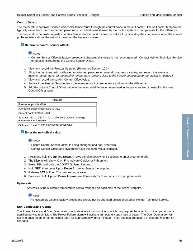
Helmer Scientific i.Series® and Horizon Series™ Freezer - Upright Service and Maintenance Manual
360370/B 45
Control SensorThe temperature controller senses unit cooler temperature through the control probe in the unit cooler. The unit cooler temperature typically varies from the chamber temperature, so an offset value is used by the control system to compensate for the difference.The temperature controller adjusts chamber temperature around the freezer setpoint by activating the compressor when the control probe registers above the setpoint based on the hysteresis value.
Determine control sensor offset:
Notes• Control Sensor Offset is factory-preset and changing this value is not recommended. Contact Helmer Technical Service for questions regarding the Control Sensor Offset.
1. View and record the Freezer Setpoint. (Reference Section 10.3)2. Allow the unit to run with calibrated monitor temperature for several compressor cycles, and record the average monitor temperature. (If the monitor temperature remains close to the freezer setpoint no further action is needed.)3. View and record the current Control Offset value.4. Subtract the Freezer Setpoint from the average monitor temperature and record the difference.5. Add the current Control Offset value to the recorded difference determined in the previous step to establish the new Control Offset value.
Example Freezer setpoint is -30.0
Average monitor temperature is -31.2
Current Control Offset is 0.3
Subtract: -31.2 - (-30.0) = -1.2; difference between average temperature and setpoint.
Add: 0.3 + (-1.2) = -0.9; new control offset value
Enter the new offset value:
Notes• Ensure Control Sensor Offset is being changed, and not Hysteresis.• Control Sensor Offset and Hysteresis have the same visual indicator.
1. Press and hold the Up and Down Arrows simultaneously for 3 seconds to enter program mode.2. The Display will show .C or .F to indicate Celsius or Fahrenheit.3. Press SELuntilonlytheCONTROLlampflashes.4. Hold SET, then press Up or Down Arrow to change the setpoint.5. Release SET button. The new setting is saved.6. Press and hold Up and Down Arrows simultaneously for 3 seconds to exit program mode.
HysteresisHysteresis is the allowable temperature control variance on each side of the freezer setpoint.
Note The Hysteresis value is factory-preset and should not be changed unless directed by Helmer Technical Service.
Non-ConfigurableAlarmsThe Power Failure and Door Open alarms indicate operational conditions which may require the attention of the operator or a qualifiedservicetechnician.ThePowerFailurealarmwillactivateimmediatelyuponlossofpower.TheDoorOpenalarmwillactivate once the door has remained open for approximately three minutes. These settings are factory-preset and may not be changed.
Horizon Series Inform
ation
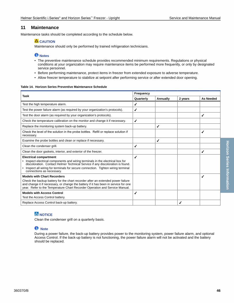
Helmer Scientific i.Series® and Horizon Series™ Freezer - Upright Service and Maintenance Manual
360370/B 46
11 MaintenanceMaintenance tasks should be completed according to the schedule below.
CAUTIONMaintenance should only be performed by trained refrigeration technicians.
Notes• The preventive maintenance schedule provides recommended minimum requirements. Regulations or physical conditions at your organization may require maintenance items be performed more frequently, or only by designated service personnel.• Before performing maintenance, protect items in freezer from extended exposure to adverse temperature.• Allow freezer temperature to stabilize at setpoint after performing service or after extended door opening.
Table 14. Horizon Series Preventive Maintenance Schedule
TaskFrequencyQuarterly Annually 2 years As Needed
Test the high temperature alarm.
Test the power failure alarm (as required by your organization’s protocols).
Test the door alarm (as required by your organization’s protocols).
Check the temperature calibration on the monitor and change it if necessary.
Replace the monitoring system back-up battery.
Checkthelevelofthesolutionintheprobebottles.Refillorreplacesolutionifnecessary.
Examine the probe bottles and clean or replace if necessary.
Clean the condenser grill.
Clean the door gaskets, interior, and exterior of the freezer.
Electrical compartment• Inspect electrical components and wiring terminals in the electrical box for discoloration. Contact Helmer Technical Service if any discoloration is found.• Inspect all wiring for terminals for secure connection. Tighten wiring terminal connections as necessary.
Models with Chart RecordersCheck the backup battery for the chart recorder after an extended power failure and change it if necessary, or change the battery if it has been in service for one year. Refer to the Temperature Chart Recorder Operation and Service Manual.
Models with Access ControlTest the Access Control battery.
Replace Access Control back-up battery.
NOTICEClean the condenser grill on a quarterly basis.
NoteDuring a power failure, the back-up battery provides power to the monitoring system, power failure alarm, and optional Access Control. If the back-up battery is not functioning, the power failure alarm will not be activated and the battery should be replaced.
Horizon Series Inform
ation

Helmer Scientific i.Series® and Horizon Series™ Freezer - Upright Service and Maintenance Manual
360370/B 47
11.1 Alarm TestsTest alarms to ensure they are working correctly. The freezer has alarms for chamber temperature, power failure, and door open (time).
Chamber Temperature Alarm Test
NOTICE• Before testing alarms, protect items stored in the unit from extended exposure to adverse temperature.• Temperature probes are fragile; handle with care.
Test the high alarm:1. Identify setting for high alarm setpoint.2. Place the glass of product simulation solution in the freezer.3. When the product simulation solution has stabilized at the chamber temperature, remove the solution from the freezer.4. Remove the monitor probe from the probe bottle.5. Place the probe in the product simulation solution, observe the temperature on the monitoring system display at which the high temperature alarm sounds.6. Compare the temperature at which the alarm sounds to the high alarm setpoint.7. Remove probe from product simulation solution.8. Place monitor probe in probe bottle, immersing it at least 2” (50 mm).
Power Failure Alarm Test
Note During a power failure, the back-up battery should continue to provide power to the monitoring system.
1. Switch AC ON/OFF switch OFF. Audible power failure alarm will activate immediately and “PoFF” (power off) will appear on the display.2. Switch AC ON/OFF switch ON. Audible power failure alarm will cease and “PoFF” will clear from the display.
Door Open Alarm Test
NoteFactory-set to three minutes and can not be changed.
1. Open freezer door and note the time.2. Afterthreeminutes,audiblealarmwillactivateandDOORALARMlampwillflash.3. Closefreezerdoor.AudibledooropenalarmwillceaseandDOORALARMlampwillstopflashing.
11.2 Test and Replace Back-up BatteriesCheck Monitoring System BatteryThe monitoring system does not indicate the charge level of the battery. Regularly test the battery and replace battery if the test fails or if the battery has been in use for one year.
Note Useonlyabatterywhichmeetsmanufacturer’sspecifications.
Test the battery:1. Switch the AC ON/OFF switch OFF.2. Display should continue to display information and the No Battery alarm should activate.3. If the display is blank, replace battery.4. Switch AC ON/OFF switch ON.
Horizon Series Inform
ation

Helmer Scientific i.Series® and Horizon Series™ Freezer - Upright Service and Maintenance Manual
360370/B 48
Check Optional Access Control System BatteryDuring an AC power failure, the Access Control back-up battery provides back-up power to the magnetic Access Control lock. Test the Access Control back-up battery to ensure it is working properly.
Test the battery:1. Ensure Access Control back-up battery key switch is switched ON.2. Switch AC ON/OFF switch OFF.3. Verify “PoFF” (power failure) message is displayed.4. Attempt to open the cabinet door, if the door remains locked, the battery is functional. If the door does not remain locked, replace the battery.5. Switch AC ON/OFF switch ON.
Chart Recorder Back-up Battery (if included)Refer to 360076-1 Temperature Chart Recorder Operation and Service Manual.
11.3 Check Probe BottleRemove the probe bottle from the bracket and inspect for cracks. Replace the bottle if necessary. Ensure the probe bottle has approximately 4 oz. (120 mL) of product simulation solution (1:1 ratio of water to propylene glycol). The propylene glycol is used to create a solution which simulates the product stored in the freezer. The product simulation solutiontemperaturereflectstheproduct’stemperatureduringnormaloperation.Failuretofillthebottlemaypreventthechambertemperature from stabilizing at the temperature setpoint. The probe should be immersed at least 2” (50 mm).
11.4 Clean the FreezerCabinet ExteriorClean glass surfaces with soft cotton cloth and glass cleaner. Clean exterior surfaces with soft cotton cloth and non-abrasive liquid cleaner.
CAUTION The condensate evaporator and water evaporation tray are hot.
Cabinet InteriorClean painted surfaces with mild detergent. Clean stainless steel surfaces with a general-purpose laboratory cleaner suitable for stainless steel.
Condenser Grill
CAUTIONDisconnect freezer from AC power when cleaning condenser grill.
If the freezer is located in an environment where it is exposed to excessive lint or dust, the condenser grill may require cleaning more frequently than stated in preventive maintenance schedule.Clean the condenser grill using a soft brush and a vacuum cleaner.
Door GasketsClean with soft cloth and mild soap and water solution.
Probe Bottles
CleanandRefillProbeBottles1. Remove all probes from bottle.2. Remove bottle from bracket and empty any remaining solution3. Clean bottle with a 1:9 ratio of bleach to water solution or a company approved equivalent oxidizing cleaner/disinfectant.4. Refillbottlewith4oz.(120mL)ofproductsimulationsolution(1:1ratioofwatertopropyleneglycol).5. Cap bottle tightly to minimize evaporation.6. Place bottle in bracket.7. Replace probes, immersing at least 2” (50 mm).
Horizon Series Inform
ation

Helmer Scientific i.Series® and Horizon Series™ Freezer - Upright Service and Maintenance Manual
360370/B 49
12 Service12.1 Refrigerant
CAUTION• Review all safety instructions prior to recharging refrigerant. Refer to Section 1.1.• Maintenance should only be performed by trained refrigeration technicians.
Notes• Use only non-CFC R404A refrigerant.• Pressure readings may vary based on chamber temperature and ambient air temperature.• Normal low side pressures are 2 psi to 4 psi when unit is functioning at standard operating temperatures and measured at the end of the compressor cycle.• Ifarefrigerantleakissuspected,Helmerrecommendsfindingandfixingtheleakpriortorechargingtheunit.
Fullinitialrefrigerantchargevariesbymodelandpowerrequirements,whichcanbefoundontheproductspecificationlabel.
Table 15. Initial Charge by Model
Model Refrigerant Power Requirements Initial Charge
120 and 125 models R404A 115 V, 60 Hz 230 V, 50/60 Hz
29.0 oz. (822 g)
12.2 Remove / Replace Unit Cooler CoverThe unit cooler must be removed when servicing the control probe, fan motor(s) or coil.
NOTICEIf unit cooler cover is not removed as detailed in this procedure the drain port may be damaged. Improper drainage may result in excessive icing and freezer’s inability to maintain temperature.
Remove unit cooler cover
CAUTIONThe condensate evaporator and water evaporation tray are hot.
1. Switch AC ON/OFF switch OFF. Disconnect the battery.2. On the back of the cabinet, peel the putty back to expose the drain tube and drain heater.3. Verify the heating element is cool. Remove the screws and loosen the pipe straps securing the drain tube to the cabinet.4. Remove the drain heater from the drain tube.5. Removethedraintubebypullingitdownward.Thedraintubeshouldseparatefromthefantubeatthe90°elbow, leaving the fan tube attached to the fan.6. Separate the drain hose inside the cabinet from the unit cooler drain port by gently twisting the drain hose from left to right to separate it from the unit cooler drain port.7. Pivot the drain tube and drain hose upward to remove the assembly from the cabinet.8. Remove top drawer, basket, or shelf from the chamber.
A
G
FED
C
B
Label DescriptionA Unit cooler cover
B Drain port
C Drain fan
D Fan tube
E Heater wires
F Heating element
G Drain tube
Horizon Series Inform
ation
Helmer Scientific i.Series® and Horizon Series™ Freezer - Upright Service and Maintenance Manual
360370/B 50
NoteUnits without the Cold-Shield panel proceed to Step 10.
9. Loosen three screws securing Cold-Shield panel to the cabinet and slide panel to disengage from screws and remove.10. Using a 5/16” socket wrench, remove the four screws securing the unit cooler cover to the top of the cabinet while supporting the cover with one hand to prevent it from dropping.11. Carefully lower the unit cooler cover to avoid damage to the fan wiring.
Install unit cooler cover1. Verify unit cooler wiring is connected and routed correctly. Wiring should be routed above the copper tube inside the unit cooler. Reconnect wires if they have separated.2. Lift the unit cooler cover into place and attach using four screws. Tighten using a 5/16” socket wrench to secure.3. From the rear of the unit, insert the drain tube through the opening into the cabinet. The drain tube should be aligned with the unit cooler drain spout inside the chamber and the connection to the fan tube at back of the unit.4. Attach the drain tube to the unit cooler drain spout and the fan tube.5. Insert the drain line heater in the drain tube at an upward angle. The black heating element should no longer be visible.6. Replace putty around the drain tube inside the cabinet.7. Reinstall top drawer, basket, or shelf if previously removed.
NoteUnits without the Cold-Shield panel proceed to Step 9.
8. Reinstall Cold-Shield panel and tighten screws to secure.9. Reattach the pipe straps to secure the drain tube to the cabinet.10. Switch AC ON/OFF switch ON. Reconnect the battery.11. Touch Mute to disable the high temperature alarm while freezer reaches operating temperature
Horizon Series Inform
ation

Helmer Scientific i.Series® and Horizon Series™ Freezer - Upright Service and Maintenance Manual
360370/B 51
13 Troubleshooting
CAUTIONReview all safety instructions prior to troubleshooting. Refer to Section 1.1.
13.1 General Operation Problems
Problem Possible Cause Action
A drawer does not slide easily.
Ice buildup in the drawer slides. Pullthedraweroutandconfirmtheslidesarefreeofice.De-iceifnecessary.
Debris in the drawer slides. Pullthedraweroutandconfirmtheslidesarefreeofdebris.Cleanifnecessary.
Drawer is misaligned or not level. Confirmbothslidesforthedraweraremountedatthesameheight.
Drawer slide is faulty. Confirmtheslideisoperatingcorrectly.Replaceifnecessary.
The door does not open easily.
Door handle is not aligned. Properly align door handle.
Debris in the hinges. Confirmthehingesarefreeofdebris.Cleanthehingesifnecessary.
Door hinges are not lubricated. Using a general-purpose grease, lubricate the pivots in the hinges.
Hinge cam is faulty. Confirmthehingecamisnotdamaged.Replacethecamifnecessary.
The display/monitor is not responding.
Digital electronics are locked because of an interruption in power.
Reset the monitoring system
“Probe Failure” is displayed on the monitor.
Probe wiring is an open circuit Check the continuity of the probe wiring and connections. Secure the connections if necessary
Confirmtheprobeisprovidingresistanceintherangeof86Ωto110Ω.Replace the probe if necessary.
13.2 Chamber Temperature Problems
Problem Possible Cause Action
The chamber temperature displayed is higher or lower than the actual temperature.
Probe bottle is empty, or the amount of solution is too low.
Checkthelevelofproductsimulationsolutioninthebottle.Cleanandrefillthebottle if necessary.
Solution in probe bottle is frozen. Refillthebottlewithnewsolution.
Primary monitor probe(s) is not calibrated.
Check the chamber temperature calibration. Change the calibration if necessary.
Digital electronics are locked due to an interruption in power.
Reset the monitoring system.
Connections for the primary monitor probe are loose.
Check primary monitor probe connections. Secure connections if necessary.
A component is faulty or internal connections are loose.
Contact Helmer Technical Service.
“Prob” appears on the display, but the chamber temperature is set correctly.
Monitor probe wiring is an open circuit.
Check the continuity of the probe wiring and connections. Secure the connections or replace the probe if necessary.
Connections for the monitor probe are loose.
Test the probe connections. Secure the connections if necessary.
A component is faulty. Contact Helmer Technical Service.
An error code displays on the monitor.
A component is faulty or internal connections are loose.
Contact Helmer Technical Service.
The chamber temperature meets an alarm condition, but the appropriate temperature alarm is not active.
Temperature alarm setpoint was changed.
Check the current setpoints for the temperature alarms. Change the setpoints if necessary.
Contact Helmer Technical Service.
The compressor runs continuously.
Freezer setpoint is set too low. Confirmthesetpointissetwithintheoperatingrangeandchangeitifnecessary.
Control probe is not reading correctly.
Check control probe reading; adjust offset if necessary.
Check probe connections at control board.
Solid state relay is faulty. Confirmtherelayisoperatingcorrectly.Replacetherelayifnecessary.
Horizon Series Inform
ation

Helmer Scientific i.Series® and Horizon Series™ Freezer - Upright Service and Maintenance Manual
360370/B 52
Problem Possible Cause Action
The chamber temperature does not stabilize at the freezer setpoint.
Circulation in the chamber is not adequate.
Checkifthereareanyitemsthatmayobstructairflowandremovethemifnecessary.
Unit cooler fan is not running. Check the voltage to the fan when door switch is activated. Replace the fan motor or door switch if necessary.
Condenser grill is dirty. Check the condenser grill. Clean it if necessary.
Ambient air temperature around the freezer is too high.
Confirmfreezerlocationmeetsrequirements.Refertotheoperationmanual.
Condensing unit fan is not running.
Check the condensing unit fan connections. Replace the fan motor if necessary.
Evaporator is covered with ice and is not exchanging heat.
Initiate a freezer defrost cycle.
Control probe is not reading correctly.
Check control probe reading; adjust offset if necessary.
Check probe connections at control board.
Refrigerant level is too low. Check the refrigeration lines for leaks and repair them if necessary. Check the refrigerant level. Recharge the refrigerant if necessary.
A component is faulty or internal connections are loose.
Contact Helmer Technical Service.
Horizon Series Inform
ation

Helmer Scientific i.Series® and Horizon Series™ Freezer - Upright Service and Maintenance Manual
360370/B 53
13.3 Alarm Activation Problems
Problem Possible Cause Action
The freezer meets an alarm condition, but the appropriate alarm is not active.
Alarm setpoint was changed. Check the current setpoints for the alarms.
A component is faulty or internal connections are loose.
Contact Helmer Technical Service.
The High Temperature alarm activates when the door is opened, then clears shortly after the door is closed.
Probe bottle is empty. Check the level of product simulation solutioninthebottle.Cleanandrefillbottle if necessary.
High temperature alarm setpoint is set too low.
Check the setpoint. Change the setpoint if necessary.
Unit cooler fan continues to run while the door is open.
Test the door switch and unit cooler fan connections. Secure the connections if necessary. Replace the door switch or fan motor if necessary.
A component is faulty or internal connections are loose.
Contact Helmer Technical Service.
The freezer is connected to power, but the AC Power Failure alarm is active.
ON/OFF AC power switch is OFF. Turn the ON/OFF AC power switch to the ON position.
Outlet connection is faulty. Verify power at the outlet. Repair the original outlet or connect to a different outlet if necessary.
Power cord is faulty. Confirmthepowercordisconnectedsecurely.Securethepowercordifnecessary.
Circuit breaker is tripped. Reset or replace the circuit breaker.
A component is faulty or internal connections are loose.
Contact Helmer Technical Service.
The Door Open alarm is activating sporadically.
Door is not closing completely. Confirmthehingecamsarenotdamaged.Replacethecamsifnecessary.
Doors are closing but not sealing completely.
Ensure door switch is being activated by the door switch plate. Adjust as needed.
Door switch is faulty. Replace the door switch.
Temperature monitor/controller board is faulty.
Contact Helmer Technical Service.
All alarms are activating sporadically.
Alarm system component is faulty or internal connections are loose..
Confirmthecircuitboardandlineconnectionsarefunctioningcorrectly.Contact Helmer Technical Service.
The “High Temperature” alarm is activating sporadically.
Primary monitor probe is not immersed in the product simulation solution.
Confirmtheprobebottleisfullofsolution,andtheprobeisplacedinthebottlecorrectly.
Upper monitor probe is not calibrated.
Confirmtheuppermonitorprobeisreadingcorrectly.Calibratetheprobeifnecessary.
A component is faulty or internal connections are loose.
Contact Helmer Technical Service.
13.4 Condensation and Icing Problems
Problem Possible Cause Action
There is excessive water in the water evaporation tray.
Humid air is entering the chamber Confirmthefreezerislevel,andthedoorisaligned,closingtightly,andsealingcorrectly. Correct issues as necessary.
Heater in the water evaporation tray is faulty.
Confirmtheheaterishotandisdrawingthecorrectcurrent(approximately0.21 A to 0.35 A for 230V model, 0.36 A to 0.56 A for 115V model). Replace the heater if necessary.
There is excessive ice in the chamber
Humid air is entering the chamber.
Confirmthefreezerislevel,andthedoorisaligned,closingtightly,andsealingcorrectly. Correct issues as necessary.
Unit cooler drain line is damaged or restricted.
Confirmtheunitcoolerdrainlineisfreeofdebrisandisnotrestricted.Removedebris if necessary.
Connection between the unit cooler and the drain line is loose.
Confirmtheconnectionissecure.Tightentheconnectionifnecessary.
There is excessive moisture on the door.
Humid air is entering the chamber.
Confirmthefreezerislevel,andthedoorisaligned,closingtightly,andsealingcorrectly.
Relative humidity around freezer is too high.
Confirmfreezerlocationmeetsrequirements.
Horizon Series Inform
ation

Helmer Scientific i.Series® and Horizon Series™ Freezer - Upright Service and Maintenance Manual
360370/B 54
Problem Possible Cause Action
After a defrost cycle, no waterflowsintothewaterevaporation tray.
Drain line is plugged. Confirmthedraintubeisfreeofdebris.Removedebrisifnecessary.
Drain line heater is faulty. Confirmthedrainlineheateriswarmtothetouch.ContactHelmerTechnicalService to resolve issues as necessary.
Defrost heater on the evaporator in the unit cooler is faulty.
Check for ice buildup on the evaporator by looking through the fan grill with aflashlight.Ifthereissignificanticebuildupinsideorbehindtheunitcooler,initiate a defrost cycle of the freezer.
Confirmdefrostheaterishotandisdrawingtheappropriatecurrentduringadefrost event (approximately 3.3 A to 5.5 A for 230V model, 7.8 A to 10.7 A for 115V model).
Replace the defrost heater if necessary.
Horizon Series Inform
ation

Helmer Scientific i.Series® and Horizon Series™ Freezer - Upright Service and Maintenance Manual
360370/B 55
14 Horizon Series™ Parts
Note• Before replacing parts, protect items in freezer from extended exposure to adverse temperature.• Allow freezer temperature to stabilize at setpoint after replacing parts or after extended door opening.• The control board assembly is sensitive to static electricity and can be damaged by electrostatic discharge. Use proper ESD precautions when handling the control board assembly.
Letter Description Part # Letter Description Part #A Temperature chart recorder (standard on plasma
freezer model, optional on laboratory freezer model)800083-1 F Bezel without optional Access Control
* = with chart recorder door800093-1*
800092-1Not
shownChart paper (52 sheets) 220419 G Bezel with optional Access Control
* = with chart recorder door800095-1
Chart recorder back-up battery 120218 800094-1
B Door lock (functions as Access Control manual override lock on models equipped with Access Control)
220540 Not shown
Alarm disable key switch 120227
C Door handle 220426 H Control board assembly (Monitoring and Control system) * = serial #’s 2015494 and greater
800006-1
D Magnetic lock 800138-1 800276-1*
E Caster (swivel with brake) 220467 I Keypad (Optional Access Control) 800007-1
DH
E
B
GA
C
F
I
Horizon Series Inform
ation

Helmer Scientific i.Series® and Horizon Series™ Freezer - Upright Service and Maintenance Manual
360370/B 56
Letter Description Part # Volts Letter Description Model Part #
A Chart recorder probe 800024-1 - Q Full shelf (includes hardware) 120 400414-1
B Primary monitor probe 800029-1 - 125 400414-2
C Probe bottle and propylene glycol kit 400922-1 - R Drawer assembly (includes drawer,
2 slides, hardware)
120 400584-2
D Unit Cooler Assembly 800870-1 115 125 400584-1
800871-1 230 Not Shown
Drawer slide wheel - 320815-1
E Unit Cooler Fan Guard (Heatcraft / Peerless) 800876-1 115/230 Drawer slide assembly (right side) 120 400541-3
800877-1 230 125 400541-1
F Unit Cooler Fan Motor (Heatcraft / Peerless) 800872-1 115 Drawer slide assembly (left side) 120 400541-4
800950-1 230 125 400541-2
800873-1 230 Roll-out basket assembly (optional includes basket, 2 slides, hardware)
120 400890-1
G Unit Cooler Fan Blade (Heatcraft / Peerless) 800874-1 115/230 125 400890-2
800875-1 230 Roll-out basket slide assembly(right side)
120 400541-3
H Unit Cooler Drain Pan (Heatcraft / Peerless) 800878-1 115/230 125 400541-1
800879-1 230 Roll-out basket slide assembly(left side)
120 400541-4
I Control Probe 800028-1 - 125 400541-2
J Fan delay/defrost termination thermostat 800085-1 - Half shelf (includes hardware) - 400413-1
K Defrost Heater (Heatcraft / Peerless) 800880-1 115 S Upper hinge bracket* = left ** = right
- 400376-2*
800881-1 230 - 400346-1**
800882-1 230 T Hinge bearings - 220375
L TXV (expansion) valve 800110-1 - U Door gasket - 320726-1
M Defrost heater high limit thermostat 800014-1 - V Door bumper - 220441
N Door switch 120380 - W Lower hinge cam (quantity 2) - 320742-1
O Strike plate replacement kit 400687-1 - X Door stop - 320763-1
P Mullion heater (behind strike plates) 800883-1 115 Y Lower hinge bracket* = left ** = right
- 400377-2*
800884-1 230 - 400377-1**
B
L
KJI
F
D
A
C
YXW
VU
TS
R
P
N
Q
O
M
H
E
G
Horizon Series Inform
ation

Helmer Scientific i.Series® and Horizon Series™ Freezer - Upright Service and Maintenance Manual
360370/B 57
CAUTION• Disconnect the freezer from AC power before opening the electrical box.• Do not remove the cover from the condensate evaporator tray.
NoteThe control board is sensitive to static electricity and can be damaged by electrostatic discharge. Use proper ESD precautions when handling the board
Letter Description Part # Volts Letter Description Part # Volts HzA Alarm buzzer 120227 - L Main power switch 120478 - -
B Defrost timer 800015-1 - M Circuit breaker, 12 A 120220 230 -
C Temperature control transformer 800119-1 115 N Back-up battery key switch (optional Access Control) 401220-1 - -
800125-1 230 O Back-up battery (optional Access Control) 120628 - -
D Solid state relay 120426 - P Monitoring system back-up battery 120399 - -
E Powerlinefilter 120400 - Q Condenser Fan Motor 800868-1 115 60Not
ShownAccess Control power supply (optional) 800035-1 - 800869-2 230 50
F Drain line fan 800885-1 115 800869-1 230 60
800886-1 230 R Condensing Unit 800866-1 115 60
G Drain line heater 800278-1 115 800867-2 230 50
800279-1 230 800867-1 230 60
H Drain line - - S Compressor Electrical Components 800864-1 115 60
I Condensate evaporator assembly (includes condensate evaporator, tray, and cover)
400790-1 115 800865-2 230 50
400790-2 230 800865-1 230 60
J Power Cable * = European models
800001-1 115 T Solenoid Valve 220547 - -
800002-1 230 U Solenoid Coil 800863-1 115 -
800003-1* 230 800017-1 230 -
K Remote alarm contacts - -
BIH
GF
E
D
A
C
R
Q
P
O
M
KN
L
J
Horizon Series Inform
ation
ST U

Helmer Scientific i.Series® and Horizon Series™ Freezer - Upright Service and Maintenance Manual
360370/B 58
15 Schematics15.1 HPFandHLFModels;120and125ConfigurationswithoutAccessControl
THESE DRAWINGS AND SPECIFICATIONS ARE THE SOLE PROPERTY OF HELMER INC. AND SHALL NOT BE REPRODUCED ORUSED AS THE BASIS FOR MANUFACTURE OR SALES OF APPARATUS WITHOUT THE APPROVAL OF HELMER INC.
L2TERMINAL
STRIP
1
L1TERMINAL
STRIP
1MULLIONHEATER
L1 IN GND
L1 OUT
RFI FILTER
L2 IN
L2 OUT
DOOR SWITCH
UNIT COOLERFAN
XN4213F
TIMER
2 4 5
MAIN POWERSWITCH
3 X N
H 4 F
DEFROST HEATERLIMIT THERMOSTAT
2
3
4
5
6
7
8
9
10
11
12
DEFROST CONTROL
CHART RECORDER XFMR
MULLION HEATER
CONDENSATE EVAPORATOR
COMPRESSOR
MULLION HEATER
CHART RECORDER XFMR
12
11
6
10
9
7
8
5
4
3
2
1
DEFROST CONTROL
CIRCUITBREAKERS
POWER CORD
JUNCTION BOX
DEFROSTCONTROL
L2-12
CONDENSATEEVAPORATOR
GROUND TERMINAL
Pow
er Line Filter
Com
pressor
TIMERRELEASE
RELAY
FAN DELAY/DEFROST
THERMOSTAT
DEFROSTHEATER
(U)
(G)
(B)
(C)
(HF)
(M)
(S)
(E)
(R)
(HJ)
SNUBBERCIRCUIT
DRAIN LINEHEATER
(T)
L2-8
DRAIN LINE HEATER DRAIN LINE HEATER
TEMP CONTROL PSU
EXTERNAL DRAIN FANEXTERNAL DRAIN FAN
EXTERNAL DRAIN FAN
L1-12
L2-2L1-2
(Q)
L1-8
L2-9L1-9
L1-4
L2-4
126
93
CONDENSING UNITFAN MOTOR
CONDENSATE EVAPORATOR
CHARTRECORDER
9V
- +
12VAC
CHART RECORDER XFMR
(CA)
L1-6 L2-6
CHARTRECORDER
BATTERYBACKUP
(CC)
(L)COMPRESSOR
SSR1
23
4 4-32VD
C+
-
MAIN POWER
230V~ / 50 Hz208/230V~ / 60 Hz
6 7 8 9 103
Unit C
ooler
External D
rain Fan
Condensate E
vaporator
(D)
2
4
5
6
TEMP CONTROL PSU
(K)
COMPRESSOR(J)L2-7
CONDENSING UNITFAN MOTOR
3
(A)
SOLENOID COIL(V)
SOLENOID VALVE(W)
12V DC POWER SUPPLY 12V DC POWER SUPPLY
EXTERIORALARM
CONTACTS
COM
NO
NC
9V
L2-5
L1-5
12VAC
(HO)
BA
TT.
C+
-N
CN
O+
-
DO
OR
CONTROLRTD
-
+
MONITORRTD
CONTROL/MONITOR BOARD(HA)
TEMPERATURECONTROL
PROBE
(HB)
CHAMBERPROBE
(HC)
ALARM KEYSWITCH
(HD)
AUDIBLEALARM
(HE)
TEMP CONTROL XFMR,No Access Control
(F) UNIT COOLER
7
12S022/F
Temp C
ontrol/Monitor P
CB
*230V ONLY
115V~ / 60 Hz
CHARTRECORDER
PROBE
(CB)
CHARTRECORDER
CHARTRECORDER
PROBE
9V
- +
12VAC
CHART RECORDER XFMR
(CA)
L1-6 L2-6
CHARTRECORDER
BATTERYBACKUP
(CB)
(CC)
Serial Number 2045348 and prior
Horizon Series Inform
ation

Helmer Scientific i.Series® and Horizon Series™ Freezer - Upright Service and Maintenance Manual
360370/B 59
15.2 HPFandHLFModels;120and125ConfigurationswithAccessControl
THESE DRAWINGS AND SPECIFICATIONS ARE THE SOLE PROPERTY OF HELMER INC. AND SHALL NOT BE REPRODUCED ORUSED AS THE BASIS FOR MANUFACTURE OR SALES OF APPARATUS WITHOUT THE APPROVAL OF HELMER INC.
L2TERMINAL
STRIP
1
L1TERMINAL
STRIP
1MULLIONHEATER
L1 IN GND
L1 OUT
RFI FILTER
L2 IN
L2 OUT
DOOR SWITCH
UNIT COOLERFAN
XN4213F
TIMER
2 4 5
MAIN POWERSWITCH
3 X N
H 4 F
DEFROST HEATERLIMIT THERMOSTAT
2
3
4
5
6
7
8
9
10
11
12
DEFROST CONTROL
MULLION HEATER
CONDENSATE EVAPORATOR
COMPRESSOR
MULLION HEATER
12
11
6
10
9
7
8
5
4
3
2
1
DEFROST CONTROL
POWER CORD
JUNCTION BOX
DEFROSTCONTROL
L2-12
CONDENSATEEVAPORATOR
GROUND TERMINAL
Pow
er Line Filter
Com
pressor
TIMERRELEASE
RELAY
FAN DELAY/DEFROST
THERMOSTAT
DEFROSTHEATER
(U)
(G)
(B)
(C)
(HF)
(M)
(S)
(E)
(R)
(HJ)
SNUBBERCIRCUIT
DRAIN LINEHEATER
(T)
L2-8
DRAIN LINE HEATER DRAIN LINE HEATER
TEMP/ACCESS CONTROLPSU
EXTERNAL DRAIN FANEXTERNAL DRAIN FAN
EXTERNAL DRAIN FAN
L1-12
L2-2L1-2
(Q)
L1-8
L2-9L1-9
L1-4
L2-4
126
93
CONDENSING UNITFAN MOTOR
CONDENSATE EVAPORATOR
CHARTRECORDER
9V
- +
(CA)
CHARTRECORDER
BATTERYBACKUP
(CC)
(L)COMPRESSOR
SSR1
23
4 4-32VD
C+
-
6 7 8 9 103
Unit C
ooler
External D
rain Fan
Condensate E
vaporator
(D)
2
4
5
6
TEMP/ACCESS CONTROLPSU
(K)
COMPRESSOR(J)L2-7
CONDENSING UNITFAN MOTOR
3
(A)
SOLENOID COIL(V)
SOLENOID VALVE(W)
12V DC POWER SUPPLY 12V DC POWER SUPPLY
Door Access Keypad*Option
(HM)
+ -
EXTERIORALARM
CONTACTS
COM
NO
NC
9V
BA
TT.
C+
-N
CN
O+
-
DO
OR
CONTROLRTD
-
+
MONITORRTD
CONTROL/MONITOR BOARD(HA)
TEMPERATURECONTROL
PROBE
(HB)
CHAMBERPROBE
(HC)
ALARM KEYSWITCH
(HD)
AUDIBLEALARM
(HE)
L2-5
L1-5
Power Supply PCBA*Access Control Option Only
8
N/L2
L1
(AXd)
F4
Battery
BYPASS ON
12V
MONITORBATTERYBACKUP
(AXe)
MAGNET KEYSWITCH
(AXa)
(F) UNIT COOLER
Door LockMagnet*Option
(AXb)
-+
7
Temp C
ontrol/Monitor P
CB
Pow
er Supply P
CB
12S022/F
*OPTIONTO CHART
RECORDER
FROM DCPower Supply
MAIN POWER
230V~ / 50 Hz208/230V~ / 60 Hz
115V~ / 60 Hz
CIRCUITBREAKERS
*230V ONLY
+ -PWR EMAG
CHARTRECORDER
PROBE
(CB)
Serial Number 2047347 and prior
Serial Number 2045348 and prior
Horizon Series Inform
ation

Helmer Scientific i.Series® and Horizon Series™ Freezer - Upright Service and Maintenance Manual
360370/B 60
Appendix A: ComplianceRegulatory Compliance
This device complies with the requirements of directive 93/42/EEC concerning Medical Devices, as amended by 2007/47/EC. Sound level is less than 70 dB(A).
EC REPEmergo EuropePrinsessegracht 202514 AP The HagueThe Netherlands
WEEE ComplianceThe WEEE symbol (right) indicates this product falls under the scope of the WEEE (Waste Electrical and Electronic Equipment) directive. When disposing of this product in countries affected by this directive:
♦ Do not dispose of this product as unsorted municipal waste. ♦ Collect this product separately. ♦ Use collection and return systems available locally.
For more information on the return, recovery, or recycling of this product, contact your local distributor.
0086

Helmer Scientific i.Series® and Horizon Series™ Freezer - Upright Service and Maintenance Manual
360370/B 61
Appendix B: Warranty
Rel.i™ Product Warranty USA and CanadaFor technical service needs, please contact Helmer at 800-743-5637 or www.helmerinc.com. Have the model and serial number available when calling.
Rapid ResolutionWhen a warranty issue arises it is our desire to respond quickly and appropriately. The service department at Helmer is there for you. Helmerwilloverseethehandlingofyourwarrantyservicefromstarttofinish.Therefore,Helmermustgiveadvanceauthorizationforall service calls and/or parts needs relating to a warranty issue. Any repeat service calls must also be authorized as well. This allows for proper diagnosis and action. Helmer will not be responsible for charges incurred for service calls made by third parties prior to authorizationfromHelmer.Helmerretainstherighttoreplaceanyproductinlieuofservicingitinthefield.
CompressorFor the warranty period listed below, Helmer will supply the refrigeration compressor, if it is determined to be defective, at no charge, including freight. Helmer will not be liable for installation, refrigerant, or miscellaneous charges required to install the compressorbeyondthefirstyearofthewarrantyperiod.
♦ i.Seriesmodelcompressorwarrantyperiodisfive(5)years. ♦ Horizon Series model compressor warranty period is three (3) years.
PartsFor a period of two (2) years, Helmer will supply at no charge, including freight, any part that fails due to defects in material or workmanshipundernormaluse,withtheexceptionofexpendableitems.Expendableitemssuchasglass,filters,lightbulbs,anddoorgasketsareexcludedfromthiswarrantycoverage.InspectionofdefectivepartsbyHelmerwillbefinalindeterminingwarranty status. Warranty procedures must be followed in all events.
LaborFor a period of one (1) year, Helmer will cover repair labor costs (including travel) and the cost of refrigerant and supplies necessary to perform authorized repairs. Repair service must be performed by an authorized Helmer service agency following the authorization process detailed above. Alternatively, your facility’s staff may work with a Helmer technician to make repairs. Labor costs for repairs made by unauthorized service personnel, or without the assistance of a Helmer technician, will be the responsibility of the end user.
Additional Warranty InformationThe time periods set forth above begin two (2) weeks after the original date of shipment from Helmer. Warranty procedures set forth above must be followed in all events.THERE ARE NO WARRANTIES WHICH EXTEND BEYOND THE DESCRIPTION ON THE FACE HEREOF. THIS WARRANTY IS EXCLUSIVE AND IN LIEU OF ALL OTHER WARRANTIES, EXPRESS OR IMPLIED, INCLUDING WITHOUT LIMITATION ANY WARRANTY OF MERCHANTABILITY OR FITNESS FOR A PARTICULAR PURPOSE. NO WARRANTIES OF MERCHANTABILITY OR FITNESS FOR PARTICULAR PURPOSE SHALL APPLY.THE LIABILITY, IF ANY, OF HELMER FOR DIRECT DAMAGES WHETHER ARISING FROM A BREACH OF ANY SALES AGREEMENT, BREACH OF WARRANTY, NEGLIGENCE, OR INDEMNITY, STRICT LIABILITY OR OTHER TORT, OR OTHERWISE WITH RESPECT TO THE GOODS OR ANY SERVICES IS LIMITED TO AN AMOUNT NOT TO EXCEED THE PRICE OF THE PARTICULAR GOODS OR SERVICES GIVING RISE TO THE LIABILITY. IN NO EVENT SHALL HELMER BE LIABLE FOR ANY INDIRECT, INCIDENTAL, CONSEQUENTIAL, OR SPECIAL DAMAGES, INCLUDING WITHOUT LIMITATION DAMAGES RELATED TO LOST REVENUES OR PROFITS, OR LOSS OF PRODUCTS.Thiswarrantydoesnotcoverdamagescausedintransit,duringinstallationbyaccident,misuse,fire,flood,oractsofGod.Further,thiswarranty will not be valid if Helmer determines that the failure was caused by a lack of performing recommended equipment maintenance (per Helmer manual) or by using the product in a manner other than for its intended use. Installation and calibration are not covered under this warranty agreement.
Outside of USA and CanadaConsult your local distributor for warranty information.

Helmer Scientific14400 Bergen Boulevard, Noblesville, IN 46060 USA
Copyright © 2018 Helmer, Inc. 360370/B