ultra-low freezer service manual - helmer scientific ... manual provides information on how to use...
TRANSCRIPT

Ultra-Low Freezer Service and Maintenance Manuali.Series®
360173-A/C
i.SeriesiUF118iUF126
i.SeriesiUF116iUF124

Document Updates The document is furnished for information use only, is subject to change without notice and should not be construed as a commitment by Helmer Scientific. Helmer Scientific assumes no responsibility or liability for any errors or inaccuracies that may appear in the informational content contained in this material. For the purpose of clarity, Helmer Scientific considers only the most recent revision of this document to be valid.
Notices and DisclaimersConfidential / Proprietary NoticesUse of any portion(s) of this document to copy, translate, disassemble or decompile, or create or attempt to create by reverse engineering or otherwise the information from Helmer Scientific products is expressly prohibited.
Copyright and TrademarkCopyright © 2017 Helmer, Inc. Helmer®, i.Series®, i.C³®, Horizon Series™, and Rel.i™ are registered trademarks or trademarks of Helmer, Inc. in the United States of America. All other trademarks and registered trademarks are the property of their respective owners. Helmer, Inc., doing business as (DBA) Helmer Scientific and Helmer.
DisclaimerThis manual is intended as a guide to provide the operator with necessary instructions on the proper use and maintenance of certain Helmer Scientific products.Any failure to follow the instructions as described could result in impaired product function, injury to the operator or others, or void applicable product warranties. Helmer Scientific accepts no responsibility for liability resulting from improper use or maintenance of its products.The screenshots and component images appearing in this guide are provided for illustrative purposes only, and may vary slightly from the actual software screens and/or product components.
Helmer Scientific14400 Bergen BoulevardNoblesville, IN 46060 USAwww.helmerinc.comISO 13485:2003 CERTIFIED Part No. 360173-A/C
Document History
Revision Date CO Supersession Revision DescriptionA 29 DEC 2014* 10184 n/a Initial release.
B 05 JAN 2016 11402 B supersedes A Added instructions for removal of compressor restraints. Updated initial charge values in Section 10.1.
C 26 FEB 2017 12665 C supersedes BReformatted content for documentation consistency and ease of use. Updated and added content and screenshots as required by software platform changes. Updated initial high stage refrigerant charge value.
* Date submitted for Change Order review. Actual release date may vary.

Helmer Scientific i.Series® Ultra-Low Freezer Service and Maintenance Manual
360173-A/C ii
Contents1 About this Manual . . . . . . . . . . . . . . . . . . . . . . . . . . . . . . . . . . . . . . . . . . . . . . . . . . . . . . . . . . . . . . . . . . . . . . . . . . . . . . . . . . . . . . . . . . . . . . . . 3
1.1 Safety Precautions and Symbols . . . . . . . . . . . . . . . . . . . . . . . . . . . . . . . . . . . . . . . . . . . . . . . . . . . . . . . . . . . . . . . . . . . . . . . . . . . . . . . 31.2 Model and Input Power . . . . . . . . . . . . . . . . . . . . . . . . . . . . . . . . . . . . . . . . . . . . . . . . . . . . . . . . . . . . . . . . . . . . . . . . . . . . . . . . . . . . . . . 41.3 Product Labels . . . . . . . . . . . . . . . . . . . . . . . . . . . . . . . . . . . . . . . . . . . . . . . . . . . . . . . . . . . . . . . . . . . . . . . . . . . . . . . . . . . . . . . . . . . . . 4
2 InstallationandConfiguration . . . . . . . . . . . . . . . . . . . . . . . . . . . . . . . . . . . . . . . . . . . . . . . . . . . . . . . . . . . . . . . . . . . . . . . . . . . . . . . . . . . . . . 52.1 Location Requirements . . . . . . . . . . . . . . . . . . . . . . . . . . . . . . . . . . . . . . . . . . . . . . . . . . . . . . . . . . . . . . . . . . . . . . . . . . . . . . . . . . . . . . . 52.2 Compressor Restraints . . . . . . . . . . . . . . . . . . . . . . . . . . . . . . . . . . . . . . . . . . . . . . . . . . . . . . . . . . . . . . . . . . . . . . . . . . . . . . . . . . . . . . . 52.3 Placement and Leveling . . . . . . . . . . . . . . . . . . . . . . . . . . . . . . . . . . . . . . . . . . . . . . . . . . . . . . . . . . . . . . . . . . . . . . . . . . . . . . . . . . . . . . 52.4 Connect Back-up Power . . . . . . . . . . . . . . . . . . . . . . . . . . . . . . . . . . . . . . . . . . . . . . . . . . . . . . . . . . . . . . . . . . . . . . . . . . . . . . . . . . . . . . 62.5 Prepare for Monitoring . . . . . . . . . . . . . . . . . . . . . . . . . . . . . . . . . . . . . . . . . . . . . . . . . . . . . . . . . . . . . . . . . . . . . . . . . . . . . . . . . . . . . . . 62.6 External Monitoring Devices . . . . . . . . . . . . . . . . . . . . . . . . . . . . . . . . . . . . . . . . . . . . . . . . . . . . . . . . . . . . . . . . . . . . . . . . . . . . . . . . . . . 82.7 Back-up Refrigeration Systems (optional) . . . . . . . . . . . . . . . . . . . . . . . . . . . . . . . . . . . . . . . . . . . . . . . . . . . . . . . . . . . . . . . . . . . . . . . . . 92.8 Back-up System Contacts . . . . . . . . . . . . . . . . . . . . . . . . . . . . . . . . . . . . . . . . . . . . . . . . . . . . . . . . . . . . . . . . . . . . . . . . . . . . . . . . . . . . . 92.8 ConfigureStorage . . . . . . . . . . . . . . . . . . . . . . . . . . . . . . . . . . . . . . . . . . . . . . . . . . . . . . . . . . . . . . . . . . . . . . . . . . . . . . . . . . . . . . . . . . 10
3 Controls . . . . . . . . . . . . . . . . . . . . . . . . . . . . . . . . . . . . . . . . . . . . . . . . . . . . . . . . . . . . . . . . . . . . . . . . . . . . . . . . . . . . . . . . . . . . . . . . . . . . . . . .113.1 Home Screen and Screensaver . . . . . . . . . . . . . . . . . . . . . . . . . . . . . . . . . . . . . . . . . . . . . . . . . . . . . . . . . . . . . . . . . . . . . . . . . . . . . . . .113.2 Home Screen Functions . . . . . . . . . . . . . . . . . . . . . . . . . . . . . . . . . . . . . . . . . . . . . . . . . . . . . . . . . . . . . . . . . . . . . . . . . . . . . . . . . . . . . .113.3 Alarm Conditions . . . . . . . . . . . . . . . . . . . . . . . . . . . . . . . . . . . . . . . . . . . . . . . . . . . . . . . . . . . . . . . . . . . . . . . . . . . . . . . . . . . . . . . . . . . 123.4 Settings . . . . . . . . . . . . . . . . . . . . . . . . . . . . . . . . . . . . . . . . . . . . . . . . . . . . . . . . . . . . . . . . . . . . . . . . . . . . . . . . . . . . . . . . . . . . . . . . . . 133.5 Sensor Calibration . . . . . . . . . . . . . . . . . . . . . . . . . . . . . . . . . . . . . . . . . . . . . . . . . . . . . . . . . . . . . . . . . . . . . . . . . . . . . . . . . . . . . . . . . . 16
4 Maintenance . . . . . . . . . . . . . . . . . . . . . . . . . . . . . . . . . . . . . . . . . . . . . . . . . . . . . . . . . . . . . . . . . . . . . . . . . . . . . . . . . . . . . . . . . . . . . . . . . . . . 204.1 Alarm Tests . . . . . . . . . . . . . . . . . . . . . . . . . . . . . . . . . . . . . . . . . . . . . . . . . . . . . . . . . . . . . . . . . . . . . . . . . . . . . . . . . . . . . . . . . . . . . . . 214.2 Upgrade System Firmware . . . . . . . . . . . . . . . . . . . . . . . . . . . . . . . . . . . . . . . . . . . . . . . . . . . . . . . . . . . . . . . . . . . . . . . . . . . . . . . . . . . 234.3 Test and Replace Back-up Battery . . . . . . . . . . . . . . . . . . . . . . . . . . . . . . . . . . . . . . . . . . . . . . . . . . . . . . . . . . . . . . . . . . . . . . . . . . . . . 234.4 Defrost Ultra-Low Freezer . . . . . . . . . . . . . . . . . . . . . . . . . . . . . . . . . . . . . . . . . . . . . . . . . . . . . . . . . . . . . . . . . . . . . . . . . . . . . . . . . . . . 244.5 Clean Ultra-Low Freezer . . . . . . . . . . . . . . . . . . . . . . . . . . . . . . . . . . . . . . . . . . . . . . . . . . . . . . . . . . . . . . . . . . . . . . . . . . . . . . . . . . . . . 26
5 Service . . . . . . . . . . . . . . . . . . . . . . . . . . . . . . . . . . . . . . . . . . . . . . . . . . . . . . . . . . . . . . . . . . . . . . . . . . . . . . . . . . . . . . . . . . . . . . . . . . . . . . . . 275.1 Refrigerant . . . . . . . . . . . . . . . . . . . . . . . . . . . . . . . . . . . . . . . . . . . . . . . . . . . . . . . . . . . . . . . . . . . . . . . . . . . . . . . . . . . . . . . . . . . . . . . 275.2 Chamber Temperature Sensor Error Recovery . . . . . . . . . . . . . . . . . . . . . . . . . . . . . . . . . . . . . . . . . . . . . . . . . . . . . . . . . . . . . . . . . . . . 275.3 Access Control Solenoid . . . . . . . . . . . . . . . . . . . . . . . . . . . . . . . . . . . . . . . . . . . . . . . . . . . . . . . . . . . . . . . . . . . . . . . . . . . . . . . . . . . . . 305.4 Exterior Door . . . . . . . . . . . . . . . . . . . . . . . . . . . . . . . . . . . . . . . . . . . . . . . . . . . . . . . . . . . . . . . . . . . . . . . . . . . . . . . . . . . . . . . . . . . . . 305.6 Casters . . . . . . . . . . . . . . . . . . . . . . . . . . . . . . . . . . . . . . . . . . . . . . . . . . . . . . . . . . . . . . . . . . . . . . . . . . . . . . . . . . . . . . . . . . . . . . . . . . 31
6 Troubleshooting . . . . . . . . . . . . . . . . . . . . . . . . . . . . . . . . . . . . . . . . . . . . . . . . . . . . . . . . . . . . . . . . . . . . . . . . . . . . . . . . . . . . . . . . . . . . . . . . 326.1 General Operation Problems . . . . . . . . . . . . . . . . . . . . . . . . . . . . . . . . . . . . . . . . . . . . . . . . . . . . . . . . . . . . . . . . . . . . . . . . . . . . . . . . . 326.2 Chamber Temperature Problems . . . . . . . . . . . . . . . . . . . . . . . . . . . . . . . . . . . . . . . . . . . . . . . . . . . . . . . . . . . . . . . . . . . . . . . . . . . . . . 336.3 Alarm Activation Problems . . . . . . . . . . . . . . . . . . . . . . . . . . . . . . . . . . . . . . . . . . . . . . . . . . . . . . . . . . . . . . . . . . . . . . . . . . . . . . . . . . . 356.4 Icing Problems . . . . . . . . . . . . . . . . . . . . . . . . . . . . . . . . . . . . . . . . . . . . . . . . . . . . . . . . . . . . . . . . . . . . . . . . . . . . . . . . . . . . . . . . . . . . 36
7 Parts . . . . . . . . . . . . . . . . . . . . . . . . . . . . . . . . . . . . . . . . . . . . . . . . . . . . . . . . . . . . . . . . . . . . . . . . . . . . . . . . . . . . . . . . . . . . . . . . . . . . . . . . . . 377.1 Exterior Front and Door . . . . . . . . . . . . . . . . . . . . . . . . . . . . . . . . . . . . . . . . . . . . . . . . . . . . . . . . . . . . . . . . . . . . . . . . . . . . . . . . . . . . . . 377.2 Interior Cabinet . . . . . . . . . . . . . . . . . . . . . . . . . . . . . . . . . . . . . . . . . . . . . . . . . . . . . . . . . . . . . . . . . . . . . . . . . . . . . . . . . . . . . . . . . . . . 387.3 Electrical Panel . . . . . . . . . . . . . . . . . . . . . . . . . . . . . . . . . . . . . . . . . . . . . . . . . . . . . . . . . . . . . . . . . . . . . . . . . . . . . . . . . . . . . . . . . . . . 397.4 Refrigeration Components and Exterior Rear . . . . . . . . . . . . . . . . . . . . . . . . . . . . . . . . . . . . . . . . . . . . . . . . . . . . . . . . . . . . . . . . . . . . . 40
8 Schematics . . . . . . . . . . . . . . . . . . . . . . . . . . . . . . . . . . . . . . . . . . . . . . . . . . . . . . . . . . . . . . . . . . . . . . . . . . . . . . . . . . . . . . . . . . . . . . . . . . . . 418.1 Electrical Schematic . . . . . . . . . . . . . . . . . . . . . . . . . . . . . . . . . . . . . . . . . . . . . . . . . . . . . . . . . . . . . . . . . . . . . . . . . . . . . . . . . . . . . . . . 418.2 Refrigeration Schematic . . . . . . . . . . . . . . . . . . . . . . . . . . . . . . . . . . . . . . . . . . . . . . . . . . . . . . . . . . . . . . . . . . . . . . . . . . . . . . . . . . . . . 42
Appendix A: Compliance . . . . . . . . . . . . . . . . . . . . . . . . . . . . . . . . . . . . . . . . . . . . . . . . . . . . . . . . . . . . . . . . . . . . . . . . . . . . . . . . . . . . . . . . . . . . . 43
Appendix B: Warranty . . . . . . . . . . . . . . . . . . . . . . . . . . . . . . . . . . . . . . . . . . . . . . . . . . . . . . . . . . . . . . . . . . . . . . . . . . . . . . . . . . . . . . . . . . . . . . . 44

Helmer Scientific i.Series® Ultra-Low Freezer Service and Maintenance Manual
360173-A/C 3
1 About this ManualThis manual provides information on how to use the i.Series® Ultra-Low Freezer. It is intended for use by end users of the freezer and authorized service technicians.Models are indicated by a distinguishing model number that corresponds to the series, type, number of doors and capacity of the freezer. For example, “iUF124” refers to an i.Series Ultra-Low Freezer with 1 door and a capacity of 24 cu ft. This manual covers all ultra-lowfreezers,whichmaybeidentifiedsingly,orbytheirsize.
1.1 Safety Precautions and Symbols
Symbols found in this document
The following symbols are used in this manual to emphasize certain details for the user:
Task Indicates procedures which need to be followed.
Note Provides useful information regarding a procedure or operating technique when using Helmer Scientificproducts.
NOTICE Advises the user against initiating an action or creating a situation which could result in damage to equipment; personal injury is unlikely.
CAUTION Advises the user against initiating an action or creating a situation which could result in damage to equipment or impair the quality of the products or cause minor injury.WARNING Advises the user against initiating an action or creating a situation which could result in damage to equipment and serious personal injury to a patient or the user.
Manufacturer
Symbols found on the units
The following symbols may be found on the freezer or freezer packaging.
Caution: Safety hazard to operator or service technician Caution: Unlock all casters
Caution: Electrocution/shock hazard Earth / ground terminal
Caution: Electrostatic discharge (ESD) hazard Protective earth / ground terminal
Compliance with European Union Directive WEEE 2002/96/EC applicable provisions.

Helmer Scientific i.Series® Ultra-Low Freezer Service and Maintenance Manual
360173-A/C 4
Avoiding Injury
Review safety instructions before installing, using, or maintaining the equipment. ♦ Before moving unit, remove contents from the chamber. ♦ Before moving unit, ensure door is closed and latched, and casters are unlocked and free of debris. ♦ Before moving unit, disconnect the AC power cord and secure the cord. ♦ When moving unit, use assistance from a second person. ♦ Never physically restrict any moving component. ♦ Avoid removing electrical service panels and access panels unless so instructed. ♦ Use appropriate gloves when handling cold internal components and stored inventory. ♦ Keep hands away from pinch points when closing the door. ♦ Avoid sharp edges when working inside the electrical compartment and refrigeration compartment. ♦ Ensure biological materials are stored at recommended temperatures determined by standards, literature, or good
laboratory practices. ♦ Use manufacturer supplied power cord only. ♦ Do not drill holes in the cabinet or door. Drilling holes may damage the insulation in models equipped with vacuum-insulated
panels, or may damage the evaporator coil, causing a loss of refrigerant. ♦ UsingtheequipmentinamannernotspecifiedbyHelmermayimpairtheprotectionprovidedbytheequipment. ♦ Thefreezerisnotconsideredtobeastoragecabinetforflammableorhazardousmaterials.
CAUTIONDecontaminate parts prior to sending for service or repair. Contact Helmer or your distributor for decontamination instructions and a Return Authorization Number.
1.2 Model and Input PowerTable 1. Model and Input Power
Model Voltage FrequencyCurrent
Draw
118
208/230 60 11.0 A126
116
124
1.3 Product LabelsThisinformationappearsontheproductspecificationlabel,locatedontherearofthefreezer.Themodelalsoappearsonalabellocated in the chamber on the upper side of the right wall.
SampleSpecificationlabel
Label Description
A Model (REF)
B Serial number
C Power requirements
C
A
B

Helmer Scientific i.Series® Ultra-Low Freezer Service and Maintenance Manual
360173-A/C 5
2 InstallationandConfiguration2.1 Location Requirements ♦ Has a dedicated 15 A grounded circuit with dedicated single point receptacle meeting the electrical requirements listed on the product specificationlabel. ♦ Is clear of direct sunlight, high temperature sources, and heating and air conditioning vents. ♦ Minimum 8” (203 mm) above, and minimum 4” (102 mm) behind. ♦ Meetslimitsspecifiedforambienttemperatureandrelativehumidity.
2.2 Compressor Restraints Note
When removing the compressor restraints from the low-stage compressor, approach from the left side of the compressor to avoid damage to the copper tubing mounted totheflooroftherefrigerationcompartment.
Remove Compressor Restraints
1. Using ½” socket and ½” open-end wrench, remove the hex bolt securing the compressor restraint under the high-stage compressor. Set hex bolt, washer and hex nut aside for use in installing rubber compressor foot (Qty.: 1 per compressor).2. Lift compressor mounting plate slightly and slide restraint out. 3. Remove rubber compressor foot and metal spacer from accessories box. 4. Slide the compressor foot under the compressor mounting plate and align hole in the foot with opening in the bottom of the freezer and mounting plate.5. Insert metal spacer in the center of rubber compressor foot.6. Insert hex bolt through bottom of freezer and up through compressor foot and mounting plate.7. Place washer and hex nut over the protruding hex bolt. Hand-thread hex nut.8. Secure using torque wrench, and tighten to 78.8 in-lbs.9. Repeat steps 1 – 8 for low-stage compressor.10. Place rear panel over refrigeration compartment and align holes in panel with threaded holes in freezer. 11. Hand thread screws and tighten using #2 Phillips screwdriver .
2.3 PlacementandLeveling Notes
• To prevent tipping, ensure door is closed and latched, and casters are unlocked and free of debris before moving freezer.• The freezer is extremely heavy. Helmer recommends two people work together to move the freezer.
1. Ensure all casters are unlocked and door is closed and latched.2. Roll freezer into place and lock casters.3. Adjust leveling feet as necessary to ensure freezer is level.4. Connect AC power cord to a grounded outlet meeting the electrical requirements.
Level the Unit
1. Set a bubble level on top of freezer cabinet. Orient the level front-to-back.2. Using a 9/16” open-end wrench, back the jam nut away from the weld nut.3. Hand-threadthelevelinglegsdownwarduntiltheymakecontactwiththefloor.4. Usinga5/8”open-endwrench,rotatethelevelinglegsdownwarduntilthefrontcasterstouchthefloor.5. Checkthebubbleleveltoensurethefreezerisparalleltothefloor(fronttoback),orangledslightlybackfromvertical.6. Checkthelevelinglegsandrearcasterstoensurethefreezercontactstheflooratfourpoints.Adjustbothlevelinglegsas necessary to achieve four contact points.7. Hand-thread the jam nuts upward until they make contact with the weld nut.8. Place a 5/8” open-end wrench on the leveling legs to prevent them from rotating while the jam nut is tightened. Using a 9/16” open-end wrench, snug the jam nuts against the weld nuts.
Compressor restraint
Rubber foot with spacer
Rubber foot installed
Rear panel

Helmer Scientific i.Series® Ultra-Low Freezer Service and Maintenance Manual
360173-A/C 6
2.4 Connect Back-up PowerThe monitoring system has a back-up battery system, enabling a period of continuous monitoring if power is lost.Battery life varies by manufacturer as well as voltage level remaining. Providing full power is available and no battery-related alarms are active, back-up power for the monitoring system is available for approximately 20 hours (the Low Battery alarm will activate after approximately 18 hours of battery use).
Notes• The monitoring system and chart recorder (if equipped) will start on battery power alone. If the freezer was previously not connected to AC power and the battery is switched on, the monitoring system and chart recorder will begin running on battery power.• If AC power is lost, the monitoring system will automatically disable some features to prolong battery power. Data collection will continue until battery power is depleted.• The back-up battery system does not operate the refrigeration system.• Useonlyaback-upbatterywhichmeetsmanufacturerspecifications.
Monitoring system / Access control back-up battery
2.5 PrepareforMonitoringThe Ultra-Low freezer is equipped with a rechargeable 12 V lead acid sealed battery. The battery is located in the electrical compartment, on the bottom left of the freezer and is switched off for shipping. Switch the battery on to provide the monitoring system with back-up power in the event of AC power failure.
Temperature SensorThe i.C3 monitoring and control system obtains temperature readings from the chamber temperature sensor. The sensor is located on the lower back wall of the chamber.
Chamber temperature sensor (located behind cover).

Helmer Scientific i.Series® Ultra-Low Freezer Service and Maintenance Manual
360173-A/C 7
Additional SensorsAdditional temperature sensors may be installed through one of the ports on the rear wall of the cabinet. The ports are located in the top-left corner and bottom-left corner. The ports consist of two plastic caps - one inside the cabinet and one on the outside. The cabinet insulationfillsthevoidbetweentheplugs.
NOTICEDo not drill holes in the cabinet. Drilling holes may damage the insulation in models equipped with vacuum-insulated panels, or may damage the evaporator coil causing a loss of refrigerant.
Notes• Use a tool with a diameter only large enough to accommodate the sensor wiring.• Helmer recommends installing additional sensors through the upper or lower rear ports provided.• Therearportsmayalsobeusedtoinstalltubingforanoptional(field-installed)CO2 / LN2 back-up refrigeration system.
Install Additional Sensor
1. Remove the plastic plugs on the outside and inside of the cabinet.2. Use a screwdriver or similar tool to pierce the insulating foam. 3. Insert the tool from the outside, through the foam, to the inside of the cabinet.4. Secure the sensor inside the cabinet as necessary.5. Seal the hole in the foam using Permagum putty or press-in cork tape, ensuring a tight seal.
Chart Recorder (optional)If installed, refer to the Temperature Chart Recorder Operation and Service Manual.The temperature chart recorder has a back-up battery system, enabling a period of continuous operation if power is lost. Battery life varies by manufacturer as well as voltage level remaining. Providing full power is available, back-up power for the chart recorder is available for up to 14 hours.
Prior to use:Calibrate chart recorder to match chamber temperature
Setup and OperationAccess chart recorder by pressing and releasing the door.
Helmer Scientific i.Series® Ultra-Low Freezer Service and Maintenance Manual
360173-A/C 8
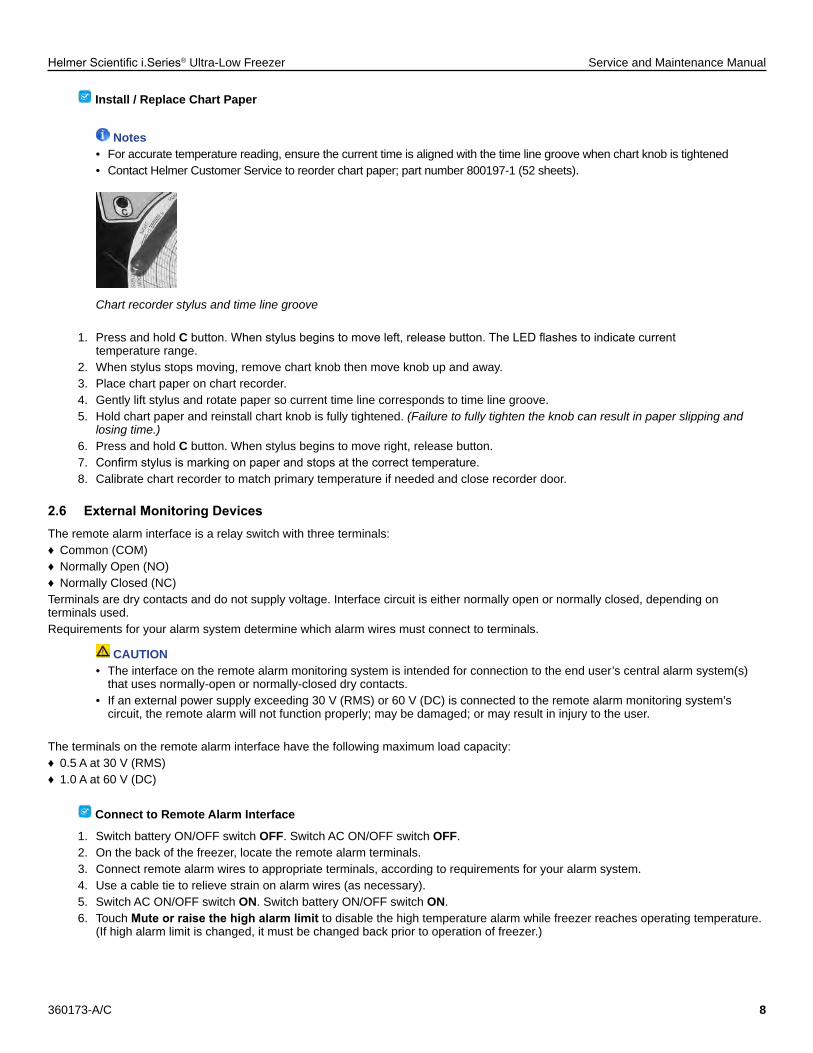
Install / Replace Chart Paper
Notes• For accurate temperature reading, ensure the current time is aligned with the time line groove when chart knob is tightened• Contact Helmer Customer Service to reorder chart paper; part number 800197-1 (52 sheets).
Chart recorder stylus and time line groove
1. Press and hold Cbutton.Whenstylusbeginstomoveleft,releasebutton.TheLEDflashestoindicatecurrent temperature range.2. When stylus stops moving, remove chart knob then move knob up and away.3. Place chart paper on chart recorder.4. Gently lift stylus and rotate paper so current time line corresponds to time line groove.5. Hold chart paper and reinstall chart knob is fully tightened. (Failure to fully tighten the knob can result in paper slipping and losing time.)6. Press and hold C button. When stylus begins to move right, release button. 7. Confirmstylusismarkingonpaperandstopsatthecorrecttemperature.8. Calibrate chart recorder to match primary temperature if needed and close recorder door.
2.6 ExternalMonitoringDevicesThe remote alarm interface is a relay switch with three terminals: ♦ Common (COM) ♦ Normally Open (NO) ♦ Normally Closed (NC)
Terminals are dry contacts and do not supply voltage. Interface circuit is either normally open or normally closed, depending on terminals used.Requirements for your alarm system determine which alarm wires must connect to terminals.
CAUTION• The interface on the remote alarm monitoring system is intended for connection to the end user’s central alarm system(s) that uses normally-open or normally-closed dry contacts.• If an external power supply exceeding 30 V (RMS) or 60 V (DC) is connected to the remote alarm monitoring system’s circuit, the remote alarm will not function properly; may be damaged; or may result in injury to the user.
The terminals on the remote alarm interface have the following maximum load capacity: ♦ 0.5 A at 30 V (RMS) ♦ 1.0 A at 60 V (DC)
Connect to Remote Alarm Interface
1. Switch battery ON/OFF switch OFF. Switch AC ON/OFF switch OFF.2. On the back of the freezer, locate the remote alarm terminals.3. Connect remote alarm wires to appropriate terminals, according to requirements for your alarm system.4. Use a cable tie to relieve strain on alarm wires (as necessary).5. Switch AC ON/OFF switch ON. Switch battery ON/OFF switch ON.6. Touch Muteorraisethehighalarmlimitto disable the high temperature alarm while freezer reaches operating temperature. (If high alarm limit is changed, it must be changed back prior to operation of freezer.)

Helmer Scientific i.Series® Ultra-Low Freezer Service and Maintenance Manual
360173-A/C 9
2.7 Back-upRefrigerationSystems(optional)A back-up refrigeration system may be installed to ensure the chamber temperature remains below a critical level in the event of an extended power failure or an equipment failure. If the chamber temperature rises to a pre-determined setpoint, the back-up refrigeration system will inject carbon dioxide (CO2) or liquid nitrogen (LN2) into the chamber to keep the chamber temperature within a specifiedrange.
NOTICE• The temperature setpoint for the CO2 / LN2 injection should be set to a value within the freezer operating range (-50 °C to -86 °C).• Do not drill holes in the cabinet. Drilling holes may damage the insulation in models equipped with vacuum-insulated panels, or may damage the evaporator coil, causing a loss of refrigerant.
InstallOptionalBack-upRefrigerationSystem
Follow the back-up refrigeration system manufacturer’s directions to install the back-up system.
Notes• Helmer recommends installing the back-up refrigeration system door switch along the handle-side of the door. This will prevent the door switch from interfering with the vacuum port, located near the top of the door.• External sensors for the back-up refrigeration system may be installed through ports in the side or rear of the freezer cabinet. • Three threaded screw holes have been provided on the interior back wall of the cabinet to assist in installing and routing the back-up refrigeration system. Holes are #8-32 thread, with Phillips screws temporarily installed.• Back-up CO2 and LN2RefrigerationSystemsareavailablefromHelmerScientific.
Threaded screw holes and distribution port for back-up refrigeration system installation
2.8 Back-up System ContactsRemote contacts are provided on the back of the freezer for the back-up refrigeration system. The back-up system may be connected to the i.C³ monitoring and control system with the remote contacts. If the back-up system is activated, the system activation will be communicated to the i.C³ through the remote contacts. An icon will be displayed on the i.C³ to indicate that the back-up system has been activated.
NOTICE
The i.C³ monitoring and control system does not control the operation of the back-up refrigeration system.
Helmer Scientific i.Series® Ultra-Low Freezer Service and Maintenance Manual
360173-A/C 10
2.8 ConfigureStorage
CAUTION• Use appropriate gloves when handling cold interior components and stored inventory.• Keep hands away from pinch points when closing the door.• Before moving shelves, ensure they are empty for safe lifting.• Maximum shelf load is not to exceed 160 lbs (73 kg).• Total freezer weight (including contents) is not to exceed 1400 lbs (635 kg).
NOTICE• Before moving storage components, protect stored items in freezer from extended exposure to adverse temperature.• When removing or replacing storage racks, do not allow the storage rack to set on the top edge of a partially-open interior door.• To avoid damage to the interior door hinges, do not apply upward or downward force to the interior doors.
ProductLoadingGuidelinesWhen loading your freezer, take care to observe the following guidelines:
♦ Never load freezer beyond capacity. ♦ Always store items within shelves.
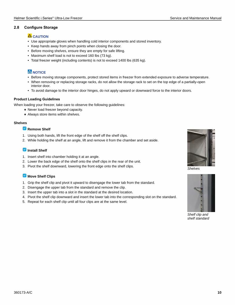
Shelves
Remove Shelf
1. Using both hands, lift the front edge of the shelf off the shelf clips.2. While holding the shelf at an angle, lift and remove it from the chamber and set aside.
Install Shelf
1. Insert shelf into chamber holding it at an angle.2. Lower the back edge of the shelf onto the shelf clips in the rear of the unit.3. Pivot the shelf downward, lowering the front edge onto the shelf clips.
Move Shelf Clips
1. Grip the shelf clip and pivot it upward to disengage the lower tab from the standard.2. Disengage the upper tab from the standard and remove the clip.3. Insert the upper tab into a slot in the standard at the desired location.4. Pivot the shelf clip downward and insert the lower tab into the corresponding slot on the standard.5. Repeat for each shelf clip until all four clips are at the same level.
Shelves
Shelf clip and shelf standard

Helmer Scientific i.Series® Ultra-Low Freezer Service and Maintenance Manual
360173-A/C 11
3 Controlsi.Series® Ultra-Low freezers are equipped with the i.C³ monitoring and control system. The i.C³ system combines temperature monitoring and control into a single user interface.
3.1 Home Screen and ScreensaverThe Home Screen is the default screen and is displayed when:
♦ The Home icon is touched from any other screen. ♦ There is no interaction for two minutes on most screens other than those used to enter a password.
Home Screen Temperature Graph Screensaver
3.2 Home Screen Functions Note
Refer to the i.C3 User Guide for options available on all i.C3 screens.
♦ View current interior cabinet temperature readings ♦ Viewmin/maxtemperatureoccurrenceforaspecifiedtimeperiod ♦ View the current system time and date ♦ Accessanyofthefivehomescreenapplications(touchi.C3 APPS for additional applications) ♦ View information about current alarm events ♦ View whether the monitoring system is running on battery power ♦ Mute audible alarms ♦ View a graph of the chamber temperature ♦ View unit ID

Helmer Scientific i.Series® Ultra-Low Freezer Service and Maintenance Manual
360173-A/C 12
3.3 Alarm ConditionsIf an alarm condition is met, an alarm activates. Some alarms are visual only; others are visual and audible. Some alarms are sent through the remote alarm interface. The table indicates if an alarm is audible (A), visual (V), or sent through the remote alarm interface (R).
NoteThe primary monitor probe was formerly referred to as the chamber temperature sensor.
Table 2. Alarm Reference
Alarm Alarm Type
High Temperature (Primary Monitor Probe) A, V, R
Low Temperature (Primary Monitor Probe) A, V, R
Sensor Failure: Chamber Temperature Control A, V, R
High Ambient Temperature V, R
Low Ambient Temperature V, R
Sensor Failure: Ambient Temperature A, V, R
Refrigeration System: High Stage Compressor Temperature A, V, R
Sensor Failure: High Stage Compressor Temperature A, V, R
Sensor Failure: High Stage Condenser Temperature A, V, R
Refrigeration System: High Stage Compressor Failure A, V, R
Refrigeration System: High Refrigerant Pressure A, V, R
Refrigeration System: Low Stage Compressor Temperature A, V, R
Sensor Failure: Low Stage Compressor Temperature A, V, R
Refrigeration System: Low Stage Compressor Failure A, V, R
Sensor Failure: Heat Exchanger Temperature A, V, R
Low Battery V, R
No Battery A, V, R
Power Failure: No AC A, V, R
Power Failure: High Voltage A, V, R
Power Failure: Low Voltage A, V, R
Power Up -
Door Open (Time) A, V, R
Clean Filter V, R
CO2 / LN2 Back-up System Active (Optional) V, R
Communication Failure 1: Control Board A, V, R
CommunicationFailure2:ConfigurationFile A, V, R
Communication Failure 3: Database A, V, R
Date / Time Change -
Helmer Scientific i.Series® Ultra-Low Freezer Service and Maintenance Manual
360173-A/C 13
3.4 Settings
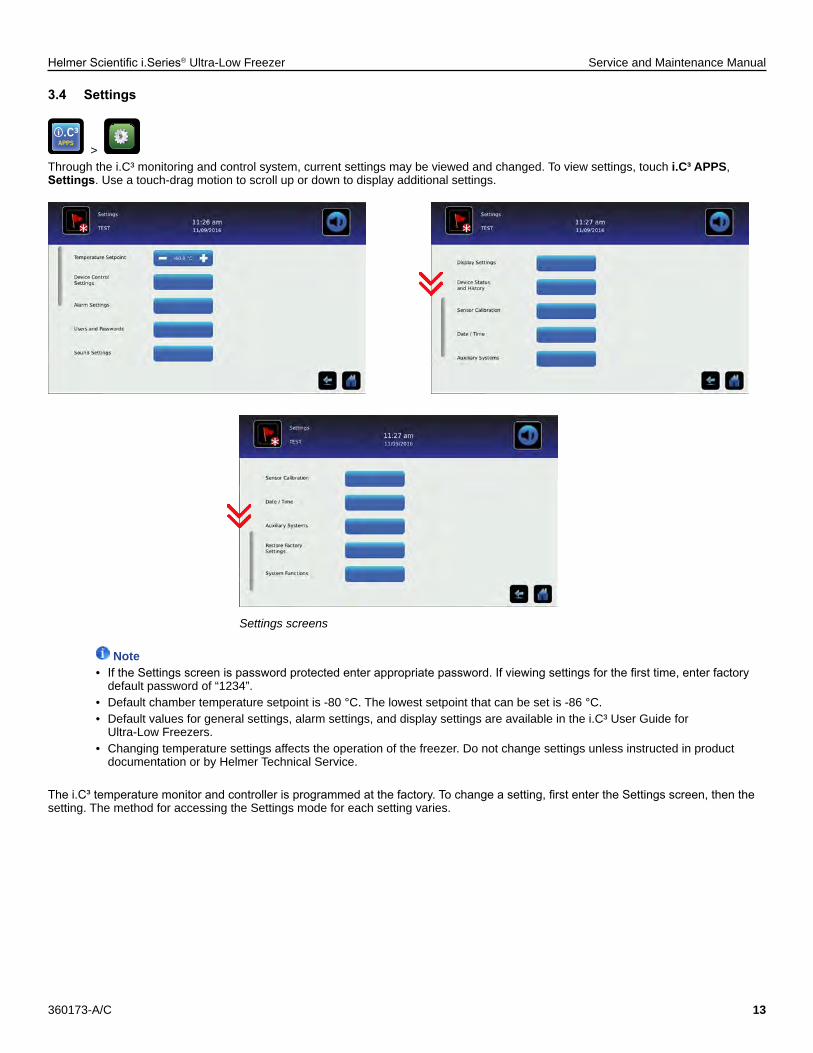
> Through the i.C³ monitoring and control system, current settings may be viewed and changed. To view settings, touch i.C³ APPS, Settings. Use a touch-drag motion to scroll up or down to display additional settings.
Settings screens
Note• IftheSettingsscreenispasswordprotectedenterappropriatepassword.Ifviewingsettingsforthefirsttime,enterfactory default password of “1234”.• Default chamber temperature setpoint is -80 °C. The lowest setpoint that can be set is -86 °C.• Default values for general settings, alarm settings, and display settings are available in the i.C³ User Guide for Ultra-Low Freezers.• Changing temperature settings affects the operation of the freezer. Do not change settings unless instructed in product documentation or by Helmer Technical Service.
Thei.C³temperaturemonitorandcontrollerisprogrammedatthefactory.Tochangeasetting,firstentertheSettingsscreen,thenthesetting. The method for accessing the Settings mode for each setting varies.

Helmer Scientific i.Series® Ultra-Low Freezer Service and Maintenance Manual
360173-A/C 14
DeviceControlSettingsDevice control settings are programmed at the factory. Setpoints can be viewed and changed through the i.C³ monitoring and control system. To view the temperature setpoint, touch i.C³ APPS, Settings, DeviceControlSettings.
Device Control Settings screen
Table 3. Setpoints
Setting Initial Factory ValueTemperature Setpoint -80.0 °C
Delay on Start-Up 1 minute
Temperature SetpointThe setpoint is the temperature at which the unit operates.
Notes• IftheSettingsscreenispasswordprotectedenterappropriatepassword.Ifviewingforthefirsttime,enterthefactory default password of “1234”.• Change the setpoint if your organization requires a chamber temperature other than -80.0 °C.• Temperature Setpoint can be adjusted through the main Settings screen and Device Control Settings.
ChangeTemperatureSetpoint1. Touch i.C³ APPS, Settings.2. Enter the Settings password.3. Touch minus (–) or plus (+) on the Temperature Setpoint spin box.
Delay on Start-UpCompressor start-up is delayed to allow the i.C3monitoringandcontrolsystemtostartfirst.
UserConfigurableAlarmSettingsThe following alarm settings may be changed by the operator. The setpoint for temperature alarms may be changed (where applicable), as well as the time delay between when the alarm condition commences and when the visual and audible alarms are initiated.
Table4.UserConfigurableAlarms
Setting Description Default Setpoint Default Time Delay
High Temperature High temperature at which alarm condition occurs -70.0 °C 0 minutes
Low Temperature Low temperature at which alarm condition occurs -90.0 °C 0 minutes
Power Failure Time after power failure occurs until alarm sounds n/a 1 minute
Probe Failure Time after probe failure occurs until alarm sounds n/a 0 minutes
Door Open (Time) Time door remains open until alarm sounds n/a 1 minute
High Ambient High temperature at which alarm condition occurs 30.0 °C 15 minutes
Low Ambient Low temperature at which alarm condition occurs 15.0 °C 15 minutes

Helmer Scientific i.Series® Ultra-Low Freezer Service and Maintenance Manual
360173-A/C 15
Alarm Settings screens
ChangeanAlarmSetting1. Touch i.C3 APPS, Settings.2. Enter the Settings password (default password is “1234”).3. Scroll down and touch AlarmSettings.4. Touch the minus (-) or plus (+) on the corresponding Setpoint spin box to change an alarm setpoint.5. Touch the minus (-) or plus (+) on the corresponding Time Delay spin box to change the time delay duration6. Touch Home to exit the Alarm Settings screen.
NoteChanging a temperature alarm setting to a value within the operating range of the freezer may trigger a temperature alarm.
Non-ConfigurableAlarmsThefollowingalarmsindicateoperationalconditionswhichrequiretheattentionoftheoperatororaqualifiedservicetechnician.
Table5.Non-ConfigurableAlarms
Alarm Description
Compressor Temperature Low stage or high stage compressor discharge temperature is too high
Condenser Temperature High stage condenser discharge temperature is too high
Clean Filter Filter cleaning interval has been reached
CO2 / LN2 Active CO2 / LN2 back-up refrigeration system has been activated
Low Battery Rechargeable battery voltage is low
No Battery Rechargeable battery voltage is too low or battery is disconnected
Refrigeration System • Refrigerant pressure is too high• High stage compressor temperature is above the upper limit• Low stage compressor temperature is above the upper limit• High stage compressor has failed• Low stage compressor has failed
Emergency Mode Chamber temperature sensor has failed, and i.C³ system is operating high stage and low stage compressors at 100% duty cycle
Communication Failure Communication Failure 1• Triggered if communication is lost between i.C³ display board and control board• Unit will continue to run with previously-saved settings• Screen will not display temperature changes or alarm conditions• i.C³ system will continue to reset until connection is re-establishedCommunication Failure 2• Triggered if communication is lost between i.C³ display board and internal system memory• Unit will continue to run with previously-saved settingsCommunication Failure 3• Triggered if the database is corrupted• The database is archived and a new database is automatically created• Unit will continue to run with previously-saved settings

Helmer Scientific i.Series® Ultra-Low Freezer Service and Maintenance Manual
360173-A/C 16
3.5 Sensor Calibration
> Sensor calibration values are programmed at the factory. Calibration values can be viewed and changed through the i.C³ monitoring and control system. To view calibration settings, touch i.C³ APPS, Settingsand scroll down to Sensor Calibration.
Sensor Calibration screens
NOTICEChanging calibration settings affects operation of the freezer. Do not change settings unless instructed in product documentation or by Helmer Technical Service.
Notes• IftheSettingsscreenispasswordprotected,entertheappropriatepassword.Ifviewingsettingsforthefirsttime,enter factory default password of “1234”.• After one hour of no interaction, the Home screen or Temperature Graph screensaver (if enabled) is displayed.• The Low Stage Compressor Discharge, Cascade Heat Exchanger, High Stage Compressor Discharge, and High Stage Condenser Discharge Offset settings are factory-preset and should not be changed unless directed by Helmer Technical Service.
Primary Monitor/Control Probe Verify primary monitor/control probe is reading chamber temperature correctly by comparing probe reading on the Sensor Calibration screen to the temperature measured by calibrated reference thermometer. If the probe is not reading correctly, change the value displayed on the monitor.
CAUTIONUse appropriate gloves when handling cold interior components and stored inventory.
Notes• The primary monitor probe was formerly referred to as the chamber temperature sensor.• Theprimarymonitor/controlprobeisfactory-calibratedandshouldbeverifiedonanannualbasis.Calibratewhenrequired or as dictated by facility standard operating procedures.• Theprimarymonitor/controlprobeis100ΩplatinumRTD.• Ensure the independent thermometer is not touching the cabinet wall or any other metallic components inside the cabinet.• Calibration must be done with an independent thermometer that is calibrated and traceable per national standards.• Initial factory calibration setting varies.• Offset value can be changed from -10.0°C to +10.0°C.

Helmer Scientific i.Series® Ultra-Low Freezer Service and Maintenance Manual
360173-A/C 17
Calibrate control/primary monitor probe
1. Move contents within the freezer to gain access to the probe located in the bottom compartment against the rear wall.2. Using a zip-tie, attach the independent thermometer to the cover surrounding the probe.3. Closethedoorandallowthechambertemperaturetostabilizeforaminimumoffiveminutes.4. Observe and note the thermometer temperature.
♦ If the temperature variance is within ±1.0 °C of the temperature displayed, calibration is not necessary. ♦ If the temperature variance is greater than ±1.0 °C of the temperature displayed, calibrate the sensor.
5. Touch, i.C³ APPS, Settings, Sensor Calibration.6. Touch minus (-) or plus (+) on the corresponding spin box to increase or decrease the value to match the measured value.7. Remove thermometer from the sensor cover.8. Replace freezer contents.
Ambient Temperature ProbeVerify ambient temperature sensor is reading ambient temperature correctly by comparing sensor reading to temperature read by an independent, calibrated and traceable thermometer. If sensor is not reading correctly, change the offset value displayed on the monitor.
CAUTIONAvoid sharp edges when working inside the refrigeration compartment.
Notes• Theambienttemperatureprobeisfactory-calibratedandshouldbeverifiedonanannualbasis.Calibratewhenrequiredor as dictated by facility standard operating procedures.• Theambienttemperatureprobeis100ΩplatinumRTD.• Ensure the independent thermometer is not touching the condenser or any other metallic components in the area.
Calibrate ambient temperature probe
1. Remove the condenser grill to gain access to the sensor.2. Using a zip-tie, attach the independent thermometer (with 5’ (1524mm) lead or greater) to the same point as the sensor.3. Allow the thermometer temperature to stabilize for a minimum of three minutes.4. Observe and note the thermometer temperature.
♦ If the temperature variance is within ±1.0 °C of the temperature displayed, calibration is not necessary. ♦ If the temperature variance is greater than ±1.0 °C of the temperature displayed, calibrate the ambient sensor.
5. Touch, i.C³ APPS, Settings, Sensor Calibration.6. Touch minus (-) or plus (+) on the Ambient offset spin box to increase or decrease the offset value until the displayed value matches the measured value.
NoteAfter saving the new temperature value, the displayed temperature may take several minutes to change to match the new value.
7. Remove thermometer from the sensor.8. Replace the condenser grill.
Factory-Calibrated SensorsThe low stage compressor discharge sensor, cascade heat exchanger sensor, high stage compressor discharge sensor, and high stage condenserdischargesensorarefactory-calibratedanddonotrequirefieldcalibration.Thesesensorsaredifficulttoreachtoverifytheaccuracyofanycalibrations.

Helmer Scientific i.Series® Ultra-Low Freezer Service and Maintenance Manual
360173-A/C 18
FactoryDefaultSettingsSettings listed below may be simultaneously returned to factory default values.
NoteThe factory default settings may not be the same as the settings that were factory-calibrated before the freezer was shipped.
Table6.RestoredSettings
Setting Restored Value
Home Screen Application Icons i.C³ APPS, Settings, Temperature Graph, Information Logs, Download
Display Brightness High (3 symbols)
Password (for Settings screen) 1234
Sounds On
Alarm Volume 9
Alarm Tone 3
Temperature Calibration Values Varies (calibrated at factory)
Low Stage Compressor Discharge Probe Offset Value 0 °C
High Stage Compressor Discharge Probe Offset Value 0 °C
Heat Exchanger Probe Offset Value 0 °C
High Stage Condenser Discharge Probe Offset Value 0 °C
Unit ID Serial number entered at factory
Date Format MM/DD/YYYY
Day Not affected (maintained in real-time clock)
Month
Year
Time Format 12-hour
Minute Not affected (maintained in real-time clock)
Hour
AM/PM
Language Language previously selected during setup
Temperature Units °C
Password Protection (for Settings screen) On
Ambient Temperature Display On
LN2 / CO2 System Input Off
USB Port On
RS-232 Port On
Access Control as Home Page On
High Chamber Temperature Alarm Setpoint -70.0 °C
High Chamber Temperature Alarm Time Delay 0 minutes
Low Chamber Temperature Alarm Setpoint -90.0 °C
Low Chamber Temperature Alarm Time Delay 0 minutes
High Ambient Temperature Alarm Setpoint 30.0 °C
High Ambient Temperature Alarm Time Delay 15 minutes
Low Ambient Temperature Alarm Setpoint 15.0 °C
Low Ambient Temperature Alarm Time Delay 15 minutes
Power Failure Alarm Time Delay 1 minute
Sensor Failure Alarm Time Delay 0 minutes
Door Open Alarm Time Delay 1 minute
Chamber Setpoint -80.0 °C
Chamber Hysteresis 0.1°C
Delay on Start-Up 1 minute

Helmer Scientific i.Series® Ultra-Low Freezer Service and Maintenance Manual
360173-A/C 19
RestoreSettings
1. Touch the i.C3Settingsicon. 2. Scroll down and touch the RestoreFactorySettingsbutton.TheRestoreFactorySettingsconfirmationboxappears.3. Touch toconfirm,or to cancel.
EditFactorySettingsSeveral of the i.C3screensandfunctionsareconfiguredatthefactory.Thescreensandfunctionslistedbelowaresetatthefactoryandmay be changed at the direction of Helmer Technical Service.
Table 7.
Setting Description
Device Control Settings Screen Toggle the Device Control Settings screen ON or OFFAlternate Home Screen Toggle the Alternate Home screen ON or OFFAccess Control Screen Toggle the Access Control screen ON or OFF

Helmer Scientific i.Series® Ultra-Low Freezer Service and Maintenance Manual
360173-A/C 20
4 MaintenanceMaintenance tasks should be completed according to the schedule below.
CAUTION• Maintenance should only be performed by trained refrigeration technicians.• Review all safety instructions prior to performing maintenance.
Notes• Itisimportanttoensurethatallscientificequipmentismaintainedregularlyforoptimumperformance.• These are recommended minimum requirements. Regulations for your organization or physical conditions at your facility
may require maintenance items to be performed more frequently, or only be designated service personnel.
Table 8. Preventive Maintenance Schedule
TaskFrequencyQuarterly Annually 2 years As Needed
Verify the monitor/chamber temperature sensor accuracy. Calibrate the sensor if necessary.
Verify the ambient temperature sensor accuracy. Calibrate the sensor if necessary.
Test the High and Low chamber and Ambient Temperature alarms.
Test the Power Failure alarm (as required by your organization’s protocols).
Test the Door Open alarm.
Inspect electrical components and wiring terminals in the electrical box for discoloration. Contact Helmer Technical Service if any discoloration is found.
Inspectandcleanthecondenserfilter.
Replace the i.C3 back-up battery
Defrost and clean the chamber, exterior door gasket, and inner doors.
NOTICE• Inspectandcleanthecondenserfilterasdirectedinthemaintenanceschedule,orwhenpromptedbythei.C³controland monitoring system.• TheCleanFilteralarmmonitorstheconditionoftheairfilterasasafetymeasure.Thealarmisdesignedtowarnifthefilter media becomes clogged such that freezer operation and product integrity will be affected.• The Clean Filter alarm could indicate a failure of the condenser fan.
Notes• During a power failure, the back-up battery provides power to the monitoring system, power failure alarm, and chart recorder (if equipped). If the back-up battery is not functioning, the power failure alarm will not be activated.• If the back-up battery does not provide power to the monitoring system during the power failure alarm test, replace the battery.• During a power failure, the Access Control lock will continue to secure the door. To access the freezer during a power failure, the override key must be used.

Helmer Scientific i.Series® Ultra-Low Freezer Service and Maintenance Manual
360173-A/C 21
4.1 Alarm Tests
> Test alarms to ensure they are working correctly. The freezer has alarms for primary monitor high temperature, primary monitor low temperature, door open (time), high ambient temperature, low ambient temperature, and power failure.
CAUTION• Use appropriate gloves when handling cold interior components and stored inventory.• Avoid sharp edges when working inside the refrigeration compartment.
Notes• Before testing alarms, protect items in freezer from extended exposure to adverse temperature.• IftheSettingsscreenispasswordprotected,entertheappropriatepassword.Ifviewingsettingsforthefirsttime,enter factory default password of “1234”. • If the i.C³ monitoring and control system did not display the appropriate alarm during the alarm test, contact Helmer Technical Service.• Temperature sensors are fragile; handle with care.
PrimaryMonitorProbeHighTemperatureAlarmTest
Notes• The primary monitor high temperature alarm test should require no more than 90 seconds.
Testthehighalarm
1. Touch, i.C³ APPS, Settings, AlarmSettingsand record the high alarm setting.2. Move contents within the freezer to gain access to the primary monitor probe.3. Using a heat gun or similar auxiliary heat source (use low setting if available), apply short bursts of heat to the probe.4. Observe the temperature on the i.C3 display at which the high temperature alarm activates.5. The alarm should activate within 2.0 °C of the high alarm setpoint. If the value is more than 2.0 °C different, contact Helmer Technical Service for further instruction.6. Remove the heat gun, replace the contents of the freezer and close the doors.
Primary Probe Low Temperature Alarm TestTo simulate a low temperature alarm condition, raise the low alarm temperature setpoint to a point above current chamber temperature displayed on the i.C³ monitoring and control system.ThePrimaryProbelowtemperaturealarmtestdoesnottesttheaccuracyofthealarm,butratherverifiesthealarmisfunctional.
Test the low alarm
1. Touch, i.C³ APPS, Settings, AlarmSettings.2. Touch the plus (+) on the Primary Monitor Probe Low Temperature spin box to change the value to 0 °C. The low temperature alarm will activate immediately.3. If the low temperature alarm does not activate, contact Helmer Technical Service.4. Touch the minus (-) on the Primary Monitor Probe Low Temperature spin box to return to the original setting.

Helmer Scientific i.Series® Ultra-Low Freezer Service and Maintenance Manual
360173-A/C 22
Power Failure Alarm TestDuring a power failure, the power failure alarm activates and the back-up battery provides power to the monitoring system.
NoteDo not switch the back-up battery switch Off during the power failure test.
Test the power failure alarm
1. Touch, i.C³ APPS, Settings, AlarmSettings.2. Touch the minus (-) or plus (+) on the Power Failure spin box to change the value to 0 minutes.3. Switch AC ON/OFF switch OFF. The power failure alarm will activate immediately.4. Switch AC ON/OFF switch ON. The power failure alarm will clear and audible alarm will cease.5. Touch the minus (-) or plus (+) on the Power Failure spin box to return to the original setting.
Door Open Alarm Test
Test the Door Open (Time) alarm
1. Touch, i.C³ APPS, Settings, AlarmSettings.2. Touch the minus (-) or plus (+) on the Door Open (Time) spin box to change the value to 0 minutes.3. Open freezer door. The door open alarm will activate immediately.4. Close freezer door. The door open alarm will clear and audible alarm will cease.5. Touch the minus (-) or plus (+) on the Door Open (Time) spin box to return to the original setting.
HighAmbientTemperatureAlarmTest
NoteEmergency Mode alarm may occur during this test. Turn back-up battery switch and main power switch OFF. After 10 seconds turn back-up battery switch and main power switch ON to clear Emergency Mode alarm.
TesttheHighAmbientTemperatureAlarm
1. Touch, i.C³ APPS, Settings, AlarmSettings 2. Scroll down and record the Ambient Probe High Temp setpoint.3. Removethecondenserfiltergrill.4. Using a heat gun or similar auxiliary heat source (use low setting if available), apply short bursts of heat to the ambient temperature probe.5. Observe the temperature on the i.C3 display at which the high ambient temperature alarm activates.6. The alarm should activate within 2.0 °C of the high alarm setpoint. If the value is more than 2.0 °C different, contact Helmer Technical Service for further instruction.7. Removetheheatgunandreinstallthecondenserfiltergrill.

Helmer Scientific i.Series® Ultra-Low Freezer Service and Maintenance Manual
360173-A/C 23
Low Ambient Temperature Alarm Test
Test the Low Ambient Temperature Alarm
1. Touch, i.C³ APPS, Settings, AlarmSettings 2. Scroll down and record the low ambient alarm setpoint.3. Touch the minus (-) on the Low Ambient Time Delay setting spin box to change the setting to 0 minutes.4. Lift the condenser grill from the magnetic anchor points at the top of the grill. Remove by pulling the grill forward to an approximate 30° angle and lifting the tabs out of the tab holes.5. Using a half-full glass of ice and water mixture, dip a clean rag or paper towel into the ice water mixture until saturated.6. Wrap the moistened rag or towel around the ambient probe, and observe the ambient display temperature begin to drop.7. Observe the ambient temperature on the i.C3 display at which the low ambient temperature alarm activates.8. Compare the recorded temperature at which the alarm activated to the low ambient alarm setpoint. The recorded temperature should be within 1ºC of the low alarm setpoint. If the alarm triggers outside of the +/- 1°C range, verify sensor calibration.9. Remove moistened rag or towels from the sensor, and replace the condenser grill.10. Touch the plus (+) on the Low Ambient Time Delay setting spin box to return to the original setting.
Non-configurableTemperatureAlarmsSometemperaturealarmsarenotuser-configurable.Assuch,thealarmsetpointcannotbechangedtosimulateahigh temperature alarm. Due to the inaccessibility of the temperature sensor, it is not recommended an alarm condition be manually simulated for these alarms.
Non-configurableTemperatureAlarms
♦ Low Stage Compressor Discharge Temperature Alarm ♦ High Stage Compressor Discharge Temperature Alarm ♦ High Stage Condenser Discharge Temperature Alarm ♦ Cascade Heat Exchanger Temperature Alarm
4.2 UpgradeSystemFirmwareHelmermayoccasionallyissueupdatesforthei.C³firmware.Followupgradeinstructionsincludedwiththefirmwareupdate.
4.3 Test and Replace Back-up Batteryi.C3MonitoringSystemBack-upBatteryOn all i.C³ screens, the Battery icon will appear in the header bar when the system is running on battery power and the screen brightness will automatically be reduced. The monitoring system will automatically disable some features to extend battery life.
Test the i.C3MonitoringSystemback-upbattery1. Turn the AC On/OFF switch OFF. The screen should continue to display information with reduced brightness and the battery icon will appear on the screen. 2. If the display is blank, replace the battery.3. Switch AC ON/OFF switch ON.
NoteUseabatterywhichmeetsmanufacturer’sspecifications.

Helmer Scientific i.Series® Ultra-Low Freezer Service and Maintenance Manual
360173-A/C 24
ReplaceMonitoringSystemBack-upBatteryThe monitoring system back-up battery is a serviceable part and available by contacting Helmer Technical Service. The battery is located behind the electrical compartment access panel below the chamber. Refer to the installation instruction included with the battery service kit.
WARNINGRemoval of the electrical compartment access panel will expose electrical wiring carrying line voltage and control voltage. Ensure the freezer is powered off before removing the access panel.
CAUTIONAvoid sharp edges when working inside the electrical compartment.
Notes• Stored inventory may be kept in the freezer while this procedure is performed.• It is recommended the chamber door not be opened until after this procedure is completed.
4.4 Defrost Ultra-Low FreezerFrost accumulation is normal. The freezer chamber and interior doors must be periodically defrosted to prevent excessive frost from interfering with door operation and storage of product, or the freezer’s ability to maintain temperature.If the freezer door or interior doors do not operate correctly, or if the freezer cannot maintain the chamber setpoint temperature, defrost the chamber.
Defrost and Clean Interior DoorsDefrost the interior doors according to the preventive maintenance schedule provided in this manual.
CAUTIONUse appropriate gloves when handling cold interior components.
Notes• This procedure does not require the freezer door to remain open for an extended period of time.• Stored inventory may be kept in the freezer while this procedure is performed.• Do not use warm water to defrost the interior doors.• A heat gun may be used to defrost the interior doors
Defrost interior doors
1. Open chamber door.2. Open interior door and lift upward to free the hinge pins from hinges to remove.3. Close chamber door.4. Allow interior door to set for approximately four hours to allow accumulated frost to melt. After four hours, verify interior door is free of frost and moisture in metal framework.5. Clean interior door with a soft cotton cloth and non-abrasive liquid cleaner.6. Wipe door with a dry cotton cloth to remove moisture.7. Reinstall interior door by aligning the hinge pins on the door with the hinges in the cabinet and lowering the interior door

Helmer Scientific i.Series® Ultra-Low Freezer Service and Maintenance Manual
360173-A/C 25
Defrost and Clean Chamber
WARNINGDo not use a secondary heat source to defrost the freezer. The use of an electrical heat source (such as a heat gun) could create an electrocution hazard if the user comes into contact with water from the defrosted chamber.
CAUTION• Use appropriate gloves when handling cold interior components and stored inventory.• Keep hands away from pinch points when closing the door.• Defrosting the freezer will create excessive water in the work area. Take necessary precautions to prevent slip hazards.
NOTICE• Before defrosting chamber, protect items in freezer from extended exposure to adverse temperature.• Do not use a secondary heat source to defrost the freezer. The use of a secondary heat source (such as a heat gun) may create additional pressure within the refrigeration system and may damage system components.• Allow chamber temperature to stabilize at setpoint before moving product back into the freezer.
NoteAll moisture must be removed before powering the freezer on. Any remaining moisture will re-freeze in the chamber and may require more frequent defrosting than indicated in the preventive maintenance schedule.
Defrost the chamber
1. Move stored product to an equivalent freezer.2. Switch back-up battery ON/OFF switch OFF; switch AC ON/OFF switch OFF; and disconnect the AC power cord from the power receptacle and remove from freezer.3. Movethefreezertoalocationwherewatercanbecapturedasthechamberthaws,preferablyclosetoafloordrain.4. Open the chamber door. Prop the door open, ensuring the method used does not damage the door gasket.5. Remove and defrost the interior doors.6. Allow the freezer to set for 24 hours to allow accumulated frost to melt. After 24 hours, check to verify that the interior is free of frost.7. Clean interior surfaces and door gasket with soft cotton cloth and non-abrasive liquid cleaner.8. Wipe the interior surfaces and door gaskets with a dry cotton cloth to remove moisture.9. Reinstall the interior doors.10. Close the chamber door.11. Removeanyaccumulatedmoisturefromthefloor.12. Move the freezer to the original location.13. Reattach the AC power cord to the freezer.14. Reconnect the AC power cord into the power receptacle; switch AC ON/OFF switch ON; and switch back-up battery ON/OFF switch ON.15. Touch Mute to disable the high temperature alarm while freezer reaches operating temperature.16. Once the freezer reaches the setpoint it is ready for use.17. Return stored product to the freezer.
Defrost and Clean Exterior Door GasketIf the exterior door gasket has excessive frost or ice build-up and requires defrosting, Helmer recommends defrosting the entire chamber. After defrost is complete, carefully inspect the door gasket for tears or damage, and ensure proper adhesion to the exterior door.

Helmer Scientific i.Series® Ultra-Low Freezer Service and Maintenance Manual
360173-A/C 26
4.5 Clean Ultra-Low Freezer
WARNINGDisconnect the freezer from AC power prior to cleaning the condenser with a liquid cleaner to prevent an electrocution hazard.
CAUTION• Avoidsharpedgeswhenremovingandinstallingthecondensergrillandfilter.• Use appropriate gloves when handling stored inventory.
NOTICE• Protect items in freezer from extended exposure to adverse temperature.• Allow chamber temperature to stabilize at setpoint before moving product back into the freezer.
Condenser
Clean the condenser
1. Lift the condenser grill upward and pivot the top edge away from the freezer. Then lift the bottom edge of the grill upward to disengage the tabs at the bottom of the grill from the freezer base and remove.2. Clean the condenser using a soft brush and a vacuum cleaner.3. Reinstall the condenser grill by inserting the tabs at the bottom of the grill into the corresponding holes in the freezer base. Pivot the top of the grill toward the freezer until the magnets engage.
Condenser FilterInenvironmentswherefreezerisexposedtoexcessivelintordust,thecondenserfiltermayrequirecleaningmorefrequentlythanstated in preventive maintenance schedule.
Cleanthecondenserfilter
1. Pivot the top of the condenser grill away from the freezer.2. Liftthefilterupwardandremovefromtheslotsonthebackofthegrill.3. Cleanthecondenserfilterwithwarmwaterandamilddetergent.4. Rinsethefilterunderwarmwater.Thefiltermustberinsedfrombacktofrontsowaterflowsintheoppositedirectionof theairflow.5. Allowthecondenserfiltertodrythoroughly.6. Reinstallthecondenserfilterbyinsertingthefilterintotheslotsonthebackofthegrill.Thefiltermustbeinstalledsothewire mesh faces toward the condenser (inside).7. Pivot the top of the grill toward the freezer until the magnets engage.
ExteriorClean the exterior surfaces of the unit with a soft cotton cloth and non-abrasive liquid cleaner.
i.C3® Touchscreen
NoteDo not use solvent or alcohol-based cleaners to clean the i.C3 touchscreen.
Clean the i.C3 touchscreen with a soft, dry cotton cloth.

Helmer Scientific i.Series® Ultra-Low Freezer Service and Maintenance Manual
360173-A/C 27
5 Service5.1 Refrigerant
CAUTION• Review all safety instructions prior to recharging refrigerant. • Maintenance should only be performed by trained refrigeration technicians.• Avoid sharp edges when working inside the refrigeration compartment.
NOTICEThe refrigeration systems are sealed at the factory. Do not connect gauge manifolds or add refrigerant to either system unless directed by Helmer Technical Service.
Full initial refrigerant charge varies by models and can be found on the chart below.
Table9.RefrigerantCharge
Model Power Requirements Refrigerant InitialCharge
iUF116 iUF118
208/230 V, 60 Hz
R-404A (high stage)R-508B (low stage)R-601 (low stage)
29 oz. (822 g)13.5 oz (383 g)0.77 oz (22 g)
iUF124iUF126
R-404A (high stage)R-508B (low stage)R-601 (low stage)
29 oz (822 g)15.3 oz. (434 g)0.89 oz (25 g)
5.2 Chamber Temperature Sensor Error RecoveryIf the i.C³ monitoring and control system loses communication with the chamber temperature sensor or if the sensor fails, the i.C³ system will operate the refrigeration system in Emergency Mode to preserve the inventory stored in the freezer.
Notes• The Emergency Mode alarm will be displayed on the Home screen only.• If the Emergency Mode alarm is active, contact Helmer Technical Service.
When the refrigeration system is operating in Emergency Mode, the high stage compressor will operate continuously and the low stage compressor will operate normally, unless one or more of the following conditions occur:
♦ An over-pressure condition in the high stage refrigeration system ♦ A second Sensor Failure alarm (compressor temperature, condenser temperature, or heat exchanger temperature) becomes
activebeyondthedurationspecifiedintheSensorFailuretimedelaysetting ♦ The cascade temperature goes above -20°C
The high stage and low stage compressors will be automatically powered off if any of the conditions above are met.The chamber temperature sensor error may be cleared and the freezer returned to normal operation by following the chamber temperature sensor error recovery procedure.
NOTICEProtect items in freezer from extended exposure to adverse temperature.
Perform error recovery
1. Switch back-up battery ON/OFF switch OFF; switch AC ON/OFF switch OFF.2. Wait 30 seconds before powering the freezer back on.3. Switch AC ON/OFF switch ON; switch back-up battery ON/OFF switch ON.

Helmer Scientific i.Series® Ultra-Low Freezer Service and Maintenance Manual
360173-A/C 30
5.3 Access Control SolenoidIn the event of an Access Control Solenoid failure, the freezer must be accessed with the override key. The Access Control Solenoid is a serviceable assembly installed in the door.
Replace Access Control SolenoidContact Helmer Technical Service to order Access Control Solenoid service kit. Follow instructions for replacement included with the service kit.
5.4 Exterior Door ReplaceHingesand/orCoversCracked or broken hinges or hinge covers can be replaced. Contact Helmer Technical Service to order Hinge and Cover service kit. Follow instructions for replacement included with the service kit.
Exterior door hinge with covers
Adjust Exterior door
Required tools:• #1 Phillips screwdriver • #20 Torx driver • Ratchet strap • Loctite 242
• #2 Phillips screwdriver • 1/2” box wrench • Straight edge / ruler • Calipers
1. Verify door gasket is outside of the desired gap of 0.46” to 0.52” (12mm to 13mm) measured between the door plastic mullion and the cabinet plastic mullion.2. Using a #2 Phillips screwdriver, remove the screws securing the hinge covers. Remove hinge covers and set screws and hinge covers aside. 3. Place the ratchet strap around the cabinet, adjacent to the hinge being adjusted and tighten to secure the door.4. Using a #1 Phillips screwdriver, remove the four screws in door-side of the hinge.5. Tighten or loosen the ratchet strap as necessary to achieve a gap of 0.46” to 0.52” (12mm to 13mm) between the door and the cabinet.6. Apply Loctite 242 to the four screws that were removed from the door-side hinge and reinstall. Tighten screws using a #1 Phillips screwdriver.7. Remove the ratchet strap.8. Verify the gap remains within tolerance. If not, repeat steps to adjust.9. Reinstall hinge covers on the hinge.10. Using a #2 Phillips screwdriver, reinstall the screws securing the hinge covers.
Door plastic mullion Cabinet plastic mullion
DoorCabinet screws
Flush alignment screw
Jam nutHinge
Door screws
Cabinet

Helmer Scientific i.Series® Ultra-Low Freezer Service and Maintenance Manual
360173-A/C 31
Aligndoorflushwithcabinet
1. Using a #2 Phillips screwdriver, remove the screws securing the hinge covers. Remove hinge covers and set screws and hinge covers aside. 2. Hold a straight-edge (ruler) on the side of the freezer, spanning the door and cabinet, adjacent to the hinge being adjusted.3. Usinga#20Torxdriver,tightenorloosentheadjustmentscrew(inthehinge)untiltherightedgeofthedoorisflushwiththe right side of the cabinet.4. While holding the adjustment screw with a #20 Torx driver, tighten the jam nut with a 1/2” box wrench.5. Reinstall hinge covers on the hinge.6. Using a #2 Phillips screwdriver, reinstall the screws securing the hinge covers.
Cabinet
Door
Checkforflushalignment
Verifydoorisalignedflushwithsideofcabinet.
5.6 CastersIf a caster is bent or broken, it can be replaced. Contact Helmer Technical Service to order a Caster service kit. Follow instructions for replacement included with the service kit.

Helmer Scientific i.Series® Ultra-Low Freezer Service and Maintenance Manual
360173-A/C 32
6 Troubleshooting
CAUTION• Review all safety instructions prior to troubleshooting.• Troubleshooting should only be performed by trained refrigeration technicians.
NOTETo order Replacement Parts, contact Helmer Technical Service (1-800-743-5637).
6.1 General Operation Problems
Problem Possible Cause Action
The exterior door does not open easily.
Exterior door handle bushings are worn.
Confirmtheexteriordoorhandleisfirmlyattachedtothefreezerdoor.Replacethe door handle bushings if the handle is loose.
Excessive frost or ice build-up on mullion because cleaned or defrosted gasket and closed while still wet.
Defrost the interior and verify it is dry before closing door.
An interior door does not open easily.
Frost accumulation around the interior door gasket.
Defrost the interior door.
Interior door hinge is bent. Replace the interior door hinge.
Interior door retaining clip is worn or bent.
Replace the interior door retaining clip.
Themonitordisplayisdifficultto read.
Screen brightness is set too low. Change the screen brightness. Touch i.C³ APPS, Brightness. Touch the icon corresponding to the desired brightness setting.
The monitoring system is not responding.
Digital electronics are locked because of an interruption in power.
Reset the monitoring system by turning battery and AC power off and back on.
“Refrigeration System” alarm is displayed on the monitor.
Refrigerant pressure or temperature istoohighduetoimproperairflow.
Ensure that freezer has been installed with proper clearances.
Check that ambient temperature is in the acceptable range.
Checktheairfilterandcondenserface,andcleanorreplaceasneeded.
Check condenser face, clean as needed.
Check the operation of the condenser fan, and repair or replace as needed.
Refrigerant pressure or temperature is too high because the freezer is not being used as intended.
Ensure that products being placed in the freezer are pre-frozen to avoid introducing an excessive heat load.
Refrigerant pressure or temperature is too high because the low stage compressor is not operating when it should be.
Check the status of the low stage compressor. Touch i.C³ APPS, Settings (enter the Settings password), Device Status. Scroll as needed to view the compressor status.
Verify CP is initiating SSR2 to be ON by checking that the LED for SSR2 is lit.
Verify control voltage is leaving the SSR2 relay.
Check the line voltage high pressure switch, ensuring switch is closed.
Check the low stage compressor start components.
Refrigerant pressure or temperature is too high because the high stage compressor is not operating when it should be.
Contact Helmer Technical Service.
One or more system components has failed.
Contact Helmer Technical Service.
“Sensor Failure” alarm is displayed on the monitor.
One or more of the temperature sensors has failed, or sensor wiring is an open circuit.
Checkthei.C³EventLogDetailscreenforthespecificsensorfailure.Touchi.C³ APPS, Information Logs, Event Logs. Touch the individual event to view the sensor failure code.
Check the sensor wire connection to the control board and secure the connection if necessary.
Confirmthesensorisprovidingresistanceintherangeof73Ωto110Ω.Replacethesensorifresistanceisoutsideofspecifiedrange.

Helmer Scientific i.Series® Ultra-Low Freezer Service and Maintenance Manual
360173-A/C 33
Problem Possible Cause Action
The chart recorder is not marking the temperature.
The chart paper knob is not tight. Tighten the chart paper knob.
Stylus pressure is not correct. Confirmstylusispressingfirmlyagainstpaper.
The chart recorder motor has stopped running.
Remove the chart paper and press the reset button (behind the chart paper). Reinstall the chart paper.
The chart recorder is defective. Replace the chart recorder.
6.2 Chamber Temperature Problems
Problem Possible Cause Action
The freezer triggers an “Emergency Mode” alarmwhen performing a high temperatur alarm test.
Temperature reading of chamber probe is too high.
Clear alarm by turning the back-up battery switch and the main power switch OFF. After 10 senconds, turn back-up battery switch and main power switch ON.
The “clean Filter” alarm is activated.
Thecleanfiltertimeintervalhasbeen reached.
Cleanthecondenserfilter,thenacknowledgethecleanfilteralarmintheeventlog to clear the alarm.
Thecondenserfilterisdirty/clogged. Verify the fan is not physically impeded and check voltage going to the fan motor. Replace if necessary.The condenser fan is not operating.
The chamber temperature displayed is higher or lower than the actual temperature.
Chamber temperature sensor is not calibrated.
Check the chamber temperature calibration. Change the calibration if necessary.
Connections for the chamber temperature sensor are loose.
Check the sensor wire connection to the control board and secure the connection if necessary.
Check the continuity of the sensor wiring. Replace the sensor if necessary.
Confirmthesensorisprovidingresistanceintherangeof73Ωto110Ω.Replacethesensorifresistanceisoutsideofspecifiedrange.
Check the CP performance by utilizing jumper at J11. Place the jumper across both pins. The screen should display 4.0°C +/-1°C.
Digital electronics are locked because of an interruption in power.
Reset the monitoring system by turning battery and AC power off and back on.
Compressor solid state relay is faulty. Confirmtherelayisoperatingcorrectly.Replacetherelayifnecessary.
A component is faulty or internal connections are loose.
Contact Helmer Technical Service.
The compressors run continuously.
Freezer setpoint is set too low. Confirmthesetpointissetwithintheoperatingrangeandchangeitifnecessary.
Chamber temperature sensor is not calibrated.
Check the chamber temperature sensor calibration. Change the calibration if necessary.
Compressor solid state relays are faulty.
Confirmthecontrolboardindicatesbothcompressorsshouldnotberunning.Touch i.C³ APPS, Settings (enter the Settings password), Device Status.
If both compressors should not be running, check the compressor solid state relays.
If the compressor solid state relays are closed, replace the relays.
i.C³ control board is faulty. Confirmthecontrolboardiscallingforbothcompressorstoberunning.Touchi.C³ APPS, Settings (enter the Settings password), Device Status.
If both compressors should be running, no further action is needed.
If both compressors should not be running, check the control board compressor relays. If the relays are closed, replace the control board.
The chamber temperature meets an alarm condition, but the appropriate temperature alarm is not active.
Temperature alarm setpoint was changed.
Check the current setpoints for the temperature alarms. Change the setpoints if necessary (refer to Section II, Item 8.3.1).

Helmer Scientific i.Series® Ultra-Low Freezer Service and Maintenance Manual
360173-A/C 34
Problem Possible Cause Action
The chamber temperature does not reach or stabilize at setpoint.
Ambient air temperature is too high. Confirmfreezerlocationmeetsrequirements.
Warm product was placed at sensor. Move product and monitor chamber temperature. Wait to see if temperature has stabilized or lowers.
Check remaining items.
Excessive frost has accumulated in the chamber.
Defrost chamber.
Temperature control sensor is faulty. Check accuracy of temperature probe.
Confirmthesensorisprovidingresistanceintherangeof73Ωto110Ω.Replacethesensorifresistanceisoutsideofspecifiedrange.
Install jumper across J11 on the CP board: Display 4°C+/-1 - NO call Helmer Technical support.
Display 4°C +/-1 - YES - CP board process is good, check connections at CP board and under connector pin, wait 8 hours to see if unit stabilizes.
Condenserfilterisdirty. Checkcondenserfilter,cleanasneeded.
Condenser fan running slowly or not at all.
Check voltage and wiring to fan motor at connector.
Check voltage output at CP board relay J42.
Replace motor.
Low stage compressor starting and stopping after 2 to 10 minutes run time.
Check cascade temperature - touch i.C3 Settings (enter password) / Device Status - Cascade temperature maintaining below -20ºC. - NO - Contact Helmer Technical Service. - YES - During pull down and starting at ~-35ºC - normal behavior. - YES - Check compressor amperage, OHMs and start components.
High Stage running: Low stage not running.
Check cascade temperature - touch i.C3 Settings (enter password) / Device Status - Cascade has to reach ~-35°C before low stage will start. Did cascade reach ~-35°C?- NO - contact Helmer Technical Service.- YES - it is normal to see the cascade heat exchanger elevate above -35°C and could reach -20°C: if this happens the low stage will cycle off NORMALLY, until the low stage reaches~-35°C and the low stage will start again. This is most typical during pull down. At normal operation when at setpoint, this will not occur.
Check i.C3 Control board for lit compressor LEDs (D21 and D22) to energize compressor relays - ON, check remaining items: OFF - Contact Helmer Technical Support.
Check i.C3 Control board for lit compressor LEDs (D21 and D22) to energize compressor relays - ON, check remaining items: OFF - Contact Helmer Technical Support.
Check solid state relay - replace if control power is present but relay is not allowing voltage to pass.
Verify operation of High pressure switch(s) control and line is not open.
Check start components.
Contact Helmer Technical Service.
Compressor(s) not running Check power to unit.
Verify call for both compressors - touch i.C3 settings (enter password) Device Status - call for both on. - NO - Reboot. - YES - Check remaining items.
Check i.C3 Control board lit compressor LEDs (D21 and D22) to energize compressor relays. - OFF - Contact Helmer Technical Support. - ON - Check remaining items.
Check solid state relay. Replace if control power is present but relay is not allowing voltage to pass.
Compressor buzzing or humming - replace start components.
Amperage check and OHM compressor. Contact Helmer Technical Support.

Helmer Scientific i.Series® Ultra-Low Freezer Service and Maintenance Manual
360173-A/C 35
Problem Possible Cause Action
Both compressors running. Check cascade temperature - touch i.C3 settings (user password) / device status and history - Cascade temperature maintaining below -20ºC BUT greater than -50ºC. Normal. Allow to stabilize.
Cascade temperature -50ºC or colder. Oil logging. Defrost unit. Low stage low on charge. Contact Helmer Technical Support to utilize tech service thermocouples.
6.3 Alarm Activation Problems
Problem Possible Cause Action
The freezer is in an alarm condition, but alarms are not audible.
Audible alarms are muted. Verifythataudiblealarmsarenotmuted.Iftimeremainingisgreaterthanfiveminutes,changeMUTEtimervaluetofiveminutesandwaituntiltimerresets.
Check alarm volume level and tone selection. Touch i.C3 Settings (enter password) / Sound Settings.
i.C³ control board is faulty. Confirmthecontrolboardisoperatingcorrectly.Replaceifnecessary.
Speaker is faulty. Replace display assembly.
A component is faulty or internal connections are loose.
Contact Helmer Technical Service.
The freezer meets an alarm condition, but the appropriate alarm is not active.
Alarm setpoint was changed. Check the current setpoints for the alarms.
A component is faulty or internal connections are loose.
Contact Helmer Technical Service.
The High Temperature alarm activates when the door is opened, then clears shortly after the door is closed.
High temperature alarm setpoint is set too low.
Check the setpoint and change it if necessary.
Connections for the chamber temperature sensor are loose.
Check the sensor wire connection to the control board and secure the connection if necessary.
A component is faulty or internal connections are loose.
Contact Helmer Technical Service.
The freezer is connected to power, but the AC Power Failure alarm is active.
Outlet connection is faulty. Verify power at the outlet. Repair the original outlet or connect to a different outlet if necessary.
Power cord is faulty. Confirmthepowercordisconnectedsecurely.Securethepowercordifnecessary.
ON/OFF AC power switch is faulty. Replace the ON/OFF AC power switch.
ON/OFF AC power switch is OFF. Switch the ON/OFF AC power switch ON.
A component is faulty or internal connections are loose.
Contact Helmer Technical Service.
Circuit breaker is tripped. Reset the circuit breaker.
Circuit breaker is faulty. Replace the circuit breaker.
Power supply board is faulty. Replace the power supply board.
Powerfilterisfaulty. Replacepowerfilter.
The Door Open alarm is activating sporadically.
Exterior door is not closing completely. Confirmthehingesarenotdamaged.Replacethehingesifnecessary.
Exterior door is closing but not sealing completely.
Defrost the exterior door gasket.
Connection for the exterior door switch is loose.
Test the switch wiring connection and secure the connection if necessary.
Exterior door switch is faulty. Replace the magnetic door switch.
i.C³ control board is faulty. Confirmthecontrolboardisoperatingcorrectly.Replaceifnecessary.
Door Open Timeout is set to zero, causing the alarm to activate immediately when the door is opened.
Check the time delay for the Door Open alarm. Change the time delay if necessary.

Helmer Scientific i.Series® Ultra-Low Freezer Service and Maintenance Manual
360173-A/C 36
Problem Possible Cause Action
The Condenser Temperature alarm is active.
Condenserfilterisdirty. Checkthecondenserfilter.Cleanifnecessary.
Side panels missing from cabinet base.
Reinstallsidepanelstoensureproperairflowacrosscondenserandcompressors.
Condenser fan is not running. Check the condenser fan wiring connection. Secure the connection if necessary.
Check power to the fan and electrical connections. If power to the fan, replace fan. If no power to the fan, call Helmer Technical Support.
Check the CP operation of relay at J42.
Connection for the condenser temperature sensor is loose.
Check the sensor wire connection to the control board and secure the connection if necessary.
Ohm out.
Condenser temperature sensor is faulty.
Check the sensor wire connection to the control board and secure the connection if necessary.
Check the continuity of the sensor wiring. Replace the sensor if necessary.
Confirmthesensorisprovidingresistanceintherangeof100Ωto115Ω.Replacethesensorifresistanceisoutsideofspecifiedrange.
The No Battery alarm is activating sporadically.
Monitoring system back-up battery voltage is low.
Replace the monitoring system back-up battery.
Power supply board voltage is incorrect.
Contact Helmer Technical Service.
The High Temperature alarm is activating sporadically.
Chamber temperature sensor is not calibrated.
Check the chamber temperature sensor calibration. Change the calibration if necessary.
A component is faulty or internal connections are loose.
Contact Helmer Technical Service.
6.4 IcingProblems
Problem Possible Cause Action
There is excessive ice in the chamber, on the interior doors, or on the exterior door gasket.
Humid air is entering the chamber. Verify the door is aligned, gap is within spec, closing tightly, and sealing correctly. Correct issues as necessary.
Check for tears, loose door gasket, or damaged door gasket. Replace if necessary.
Defrost the chamber, exterior door gasket, and interior doors if necessary.
Exterior door is not closing completely.
Defrost the exterior door gasket if necessary
Confirmthehingesarenotdamaged.Replacethehingesifnecessary.
Confirmdoorgapsandalignmentareappropriate.
Check door latch to ensure it is securing and remains secure.
Relative humidity around freezer is too high.
Confirmfreezerlocationmeetsrequirements.

Helmer Scientific i.Series® Ultra-Low Freezer Service and Maintenance Manual
360173-A/C 37
7 Parts7.1 Exterior Front and Door
Notes• Before replacing parts, protect items in freezer from extended exposure to adverse temperature.• Allow freezer temperature to stabilize at setpoint after replacing parts or after extended door opening.• The i.C³ display assembly is sensitive to static electricity and can be damaged by electrostatic discharge. Use proper ESD precautions when handling the display assembly.
Label Description Model Part # Label Description Model Part #
A Exterior door gasket iUF116 800176-1 O Front bezel (with chart recorder door) iUF116 800191-2
iUF118 800176-2 iUF118 800190-2
iUF124 800177-1 iUF124 800193-2
iUF126 800177-2 iUF126 800192-2
B Access Control solenoid assembly - - Not Shown
Front bezel (without chart recorder door) iUF116 800191-1
C Latch roller - - iUF118 800190-1
D Door handle bushing - - iUF124 800193-1
E Padlock hasp - - iUF126 800192-1
F AC ON/OFF switch - 800171-1 P Condenser grill - 800202-1
G Circuit breakers - 800172-1 Q Condensergrillfilter - 800159-1
H Monitoring system back-up battery switch - 800173-1 R Power cable - -
I Chart recorder - 800196-1 S Interface cable - -
J Chart paper (52 sheets) - 800197-1 T Display board - -K Chart recorder door - - U Speaker - -L Door handle with key lock, electronic lock,
& padlock hasp- - V Touchscreen - -
M Door (includes handle, handle bushings, gasket, vacuum port, and Access Control solenoid)
- - W Display assembly (includes interface cable, power cable, display board, touch screen, speaker, and bezel)
- 800165-1
N Caster (swivel with brake) - 800188-1 X Hinge assembly (includes hinge and hinge covers) - 800178-1Not Shown
Leveling legs - 800199-1 Y Vacuum port - 800175-1
B
L
KJ
F
E
D
A
C
NO Q
Y
X
W
U
S
P
T
R
G
H
I
M
V

Helmer Scientific i.Series® Ultra-Low Freezer Service and Maintenance Manual
360173-A/C 38
7.2 Interior Cabinet
NOTICE• When removing or replacing storage racks, do not allow the storage rack to set on the top edge of a partially-open interior door.• To avoid damage to the interior door hinges, do not apply upward or downward force to the interior doors.
Label Description Model Part # Label Description Model Part #
A Inner door (the inner doors of the top three compartments of the iUF118 and iUF126 models are 9.25” tall. All other inner doors are 12.25” tall)
iUF116/iUF118 12.25” 800183-1 E Inner door catch - 800186-1
iUF118 9.25” 800183-2 F Inner door mullion gasket iUF116 800187-2
iUF124/iUF126 12.25” 800183-3 iUF118 800187-1
iUF126 9.25” 800183-4 iUF124 800187-4
B Inner door hinge - 800185-1 iUF126 800187-3
C Inner door gasket iUF116 800184-1 G Shelf - -
iUF118 800184-1 H Shelf standard - -
iUF124 800184-3 I Shelf clip - -
iUF126 800184-3 J Chamber temperature sensor wire cover - -
D Inner door retaining clip - 800186-1 K Chamber / chart recorder temperature sensor (behind cover)
- 800169-6
B
K
JF
ED
A
C
G
HI

Helmer Scientific i.Series® Ultra-Low Freezer Service and Maintenance Manual
360173-A/C 39
7.3 Electrical Panel
CAUTION• Disconnect the freezer from AC power before removing the access panel.• Avoid sharp edges when working inside the electrical compartment.
NoteThe i.C³ control board is sensitive to static electricity and can be damaged by electrostatic discharge. Use proper ESD precautions when handling the control board.
Label Description Part # Label Description Part #
A i.C³ control board 800167-1 D High stage compressor relay 800170-1
B Power supply board 800168-1 E Power management module (optional) 800194-1
C Low stage compressor relay 800170-1 F Monitoring system/Access Control back-up battery 800174-1
B
D
A
C E F

Helmer Scientific i.Series® Ultra-Low Freezer Service and Maintenance Manual
360173-A/C 40
7.4 RefrigerationComponentsandExteriorRear
CAUTION• Disconnect the freezer from AC power before removing the access panel.• Avoid sharp edges when working inside the refrigeration compartment.
NoteThe TXV (thermal expansion valve) is not a serviceable component. To replace the TXV, the cascade heat exchanger assembly must be replaced.
Label Description Part # Label Description Part #
A High stage compressor discharge temperature sensor 800169-2 Q USB port -
B Low stage compressor 800162-1 R RS-232 serial port -
C Low stage compressor discharge temperature sensor 800169-4 S Remote alarm interface -
D Receiver - T LN2 / CO2 back-up system interface -
E Expansion tank balancing line (low stage) 800164-1 U AC power connector -
F Dryer (high stage) - V Condenser 800153-1
G Dryer (low stage) - W Condenser fan motor (includes fan blade) 800154-1
H High stage solenoid (kit includes valve, coil, and dryer) 800158-1 X High stage compressor start components 800151-1
I Expansion tank (low stage) - Y Low stage compressor start components 800152-1
J Oil separator (low stage) - Z Low stage high-pressure safety switch (line voltage) 800161-1
K Cascade heat exchanger assembly with TXV 800156-1 AA Low stage high-pressure safety switch (control voltage) 800160-1
L Cascade exchanger temperature sensor 800169-1 BB High stage compressor 800155-1
M Capillary metering line (low stage) 800163-1 CC High stage condenser discharge temperature sensor 800169-3
N TXV (thermal expansion valve) 800157-1 Not Shown
Ambient temperature sensor 800169-1
O Dryer (low stage) -
P RJ-45 Ethernet port -
B
M
L
J
DA C
H
G
FE
I
V
U
TS
Q
O
R
P
N
AAZYXW BB CC
K

Helmer Scientific i.Series® Ultra-Low Freezer Service and Maintenance Manual
360173-A/C 41
8 Schematics8.1 Electrical Schematic

Helmer Scientific i.Series® Ultra-Low Freezer Service and Maintenance Manual
360173-A/C 42
8.2 RefrigerationSchematic
low pressure gas (warm)
low pressure gas (warm)
low pressure gas (cool)
low pressure liquid
high pressure liquid (cool)
high pressuregas (cool)
high pressure gas (warm)
high pressure gas (warm / desuperheated)
high pressure gas (hot)
high pressure gas (hot)
R-508B/R-601
LOWSTAGE
highpressureliquid (cool) low pressure
gas (cool)Low Stage /R-508B/R-601
highpressureliquid (cold)
low pressure gas (warm)
low pressure gas (cool)
low pressure liquid
high pressure liquid (cool)
high pressure liquid (warm)
high pressureliquid (warm)
high pressure gaslow pressure gas (warm)R-404A
HIGHSTAGE
high pressure liquid (warm)High Stage / R-404A
AMBIENT AIRINTAKE
FILTER DRIER
CONDITIONEDSPACE
-80°C(inside walls)EVAPORATOR
MULLION HEATER(around door frame)
CAPILLARYTUBES
SUCTION LINEHEAT EXCHANGER
CAPILLARY TUBE
EXPANSIONTANK
OILSEPARATOR
LOW STAGECOMPRESSOR
PRESSURESWITCHES
(high stage evap /low stage cond)
CASCADE HEATEXCHANGER
THERMAL EXPANSIONVALVE (TXV)
FILTER DRIER
RECEIVER
SUCTIONLINE HEAT
EXCHANGER
CONDENSER
CONDENSERFAN
HIGH STAGE COMPRESSORAIR FILTER
DISTRIBUTOR
P P
SUBCOOLHEAT
EXCHANGER
TC8
TC7TC6
TC5
TC4
TC3
TC2
TC1
AN7
RTD5
RTD4
RTD3
RTD2
RTD1
Helmer Scientific i.Series® Ultra-Low Freezer Service and Maintenance Manual
360173-A/C 43
Appendix A: ComplianceRegulatoryCompliance
ThisproductiscertifiedtoapplicableULandCSAstandardsbyaNRTL.
WEEE ComplianceThe WEEE (waste electrical and electronic equipment) symbol (right) indicates compliance with European Union Directive WEEE 2002/96/EC and applicable provisions. The directive sets requirements for labeling and disposal of certain products in affected countries. When disposing of this product in countries affected by this directive:
♦ Do not dispose of this product as unsorted municipal waste. ♦ Collect this product separately. ♦ Use collection and return systems available locally.
For more information on the return, recovery, or recycling of this product, contact your local distributor.
ElectromagneticComplianceThisdeviceissuitableforuseinaspecificelectromagneticenvironment.Theenduserofthisdeviceisresponsibleforensuringthedevice is used in compliance with the following European Union directives and standards regarding EMC (electromagnetic compliance):EMC Directive 2004/108/EC with Standards
♦ EN 55011:2009, inc. A1:2010 ♦ EN 61000-3-2:2006, inc. A2:2009 Electromagnetic compatibility (EMC) Part 3-2 ♦ EN 61000-3-3:2008 Electromagnetic compatibility (EMC) Part 3-3 ♦ EN 61000-6-1:2007 Electromagnetic compatibility

Helmer Scientific i.Series® Ultra-Low Freezer Service and Maintenance Manual
360173-A/C 44
Appendix B: Warranty
Rel.i™ Product Warranty USA and CanadaFor technical service needs, please contact Helmer at 800-743-5637 or www.helmerinc.com. Have the model and serial number available when calling.
Rapid ResolutionWhen a warranty issue arises it is our desire to respond quickly and appropriately. The service department at Helmer is there for you. Helmerwilloverseethehandlingofyourwarrantyservicefromstarttofinish.Therefore,Helmermustgiveadvanceauthorizationforall service calls and/or parts needs relating to a warranty issue. Any repeat service calls must also be authorized as well. This allows for proper diagnosis and action. Helmer will not be responsible for charges incurred for service calls made by third parties prior to authorizationfromHelmer.Helmerretainstherighttoreplaceanyproductinlieuofservicingitinthefield.
CompressorFor the warranty period listed below, Helmer will supply the refrigeration compressor, if it is determined to be defective, at no charge, including freight. Helmer will not be liable for installation, refrigerant, or miscellaneous charges required to install the compressor beyondthefirstyearofthewarrantyperiod.
♦ i.Seriesmodelcompressorwarrantyperiodisfive(5)years.
PartsFor a period of two (2) years, Helmer will supply at no charge, including freight, any part that fails due to defects in material or workmanshipundernormaluse,withtheexceptionofexpendableitems.Expendableitemssuchasglass,filters,lightbulbs,doorgaskets, and monitoring system back-up battery are excluded from this warranty coverage. Inspection of defective parts by Helmer will befinalindeterminingwarrantystatus.Warrantyproceduresmustbefollowedinallevents.
LaborFor a period of two (2) years, Helmer will cover repair labor costs (including travel) and the cost of refrigerant and supplies necessary to perform authorized repairs. Repair service must be performed by an authorized Helmer service agency following the authorization process detailed above. Alternatively, your facility’s staff may work with a Helmer technician to make repairs. Labor costs for repairs made by unauthorized service personnel, or without the assistance of a Helmer technician, will be the responsibility of the end user.
Additional Warranty InformationThe time periods set forth above begin two (2) weeks after the original date of shipment from Helmer. Warranty procedures set forth above must be followed in all events.THERE ARE NO WARRANTIES WHICH EXTEND BEYOND THE DESCRIPTION ON THE FACE HEREOF. THIS WARRANTY IS EXCLUSIVE AND IN LIEU OF ALL OTHER WARRANTIES, EXPRESS OR IMPLIED, INCLUDING WITHOUT LIMITATION ANY WARRANTY OF MERCHANTABILITY OR FITNESS FOR A PARTICULAR PURPOSE. NO WARRANTIES OF MERCHANTABILITY OR FITNESS FOR PARTICULAR PURPOSE SHALL APPLY.THE LIABILITY, IF ANY, OF HELMER FOR DIRECT DAMAGES WHETHER ARISING FROM A BREACH OF ANY SALES AGREEMENT, BREACH OF WARRANTY, NEGLIGENCE, OR INDEMNITY, STRICT LIABILITY OR OTHER TORT, OR OTHERWISE WITH RESPECT TO THE GOODS OR ANY SERVICES IS LIMITED TO AN AMOUNT NOT TO EXCEED THE PRICE OF THE PARTICULAR GOODS OR SERVICES GIVING RISE TO THE LIABILITY. IN NO EVENT SHALL HELMER BE LIABLE FOR ANY INDIRECT, INCIDENTAL, CONSEQUENTIAL, OR SPECIAL DAMAGES, INCLUDING WITHOUT LIMITATION DAMAGES RELATED TO LOST REVENUES OR PROFITS, OR LOSS OF PRODUCTS.Thiswarrantydoesnotcoverdamagescausedintransit,duringinstallationbyaccident,misuse,fire,flood,oractsofGod.Further,thiswarranty will not be valid if Helmer determines that the failure was caused by a lack of performing recommended equipment maintenance (per Helmer manual) or by using the product in a manner other than for its intended use. Installation and calibration are not covered under this warranty agreement.
Outside of USA and CanadaConsult your local distributor for warranty information.
END OF MANUAL

Helmer Scientific i.Series® Ultra-Low Freezer Service and Maintenance Manual
360173-A/C 45

Helmer Scientific14400 Bergen Boulevard, Noblesville, IN 46060 USA
Copyright © 2017 Helmer, Inc. 360173-A/C