front end loader blades - curtis industries...front end loader blades for tractor and skid-steer...
TRANSCRIPT

FRONT END LOADER BLADESFor Tractor and Skid-Steer Loaders
Assembly & Mounting Instructions
Curtis Industries Inc. LLC, 111 Higgins St., Worcester, MA 01606 TEL: (800) 343-7676 FAX: (508) 854-3377 For Parts and information visit us at www.Curtisindustries.netCurtis Industries Inc. LLC, reserves the right to change product design or specifications without notice or liability.
Curtis Snow Plows are protected by the following U.S. Patent Numbers: 6,145,222 and 6,209,231 Licensed under U.S. Patent Number 5,568,694 & Canadian Patent Number 2,137,853.Other patents pending.
Do not attempt to install or operate Front End Loader Bladewithout reading and understanding all Warnings and Instructionsin this Manual and on the Loader Blade.
WARNING
ALWAYS travel at reduced speed when Loader Blade is attached.ALWAYS ensure Lift Chain (if used) is securely attached to Grab Hook.ALWAYS familiarize yourself with area to be plowed. DO NOT exceed 10 mph when plowing snow. DO NOT exceed 5 mph if obstructions could be encountered when plowing.ALWAYS lower Loader Blade to ground when not in use.DO NOT position any part of your body under Loader Blade.DO NOT use any part of your body when dislodging an obstruction from Loader Blade Assembly.DO NOT service Loader Blade in tripped condition. Dangerous release of stored energy may result.
1 of 14
NOTE: Curtis F.E.L.B.’s are suited for installation on Tractors and Skid Steer Vehicles up to 47HP.
F.E.L.B. Standard Mount - Part Number 5FBMSBF.E.L.B. Skid Steer Mount - Part Number 5FBMSSF.E.L.B. John Deere Quick Attach Mount - Part Number 5FBMQA
Rev A October 11th, 2012

Figure 1. Front End Loader Blade Illustrated Parts List
Trac
tor Arm
s
Trac
tor Arm
s
1
7
8
3
Byp
ass
Rel
ief V
alve
See
Det
ail 22
6
2 4
20
4
18
18 19
2326
25
25
16
15
5
9
1211
10
13
1421
17
24
28
DE
TAIL
27
27
28
2 of 14
3 of 14
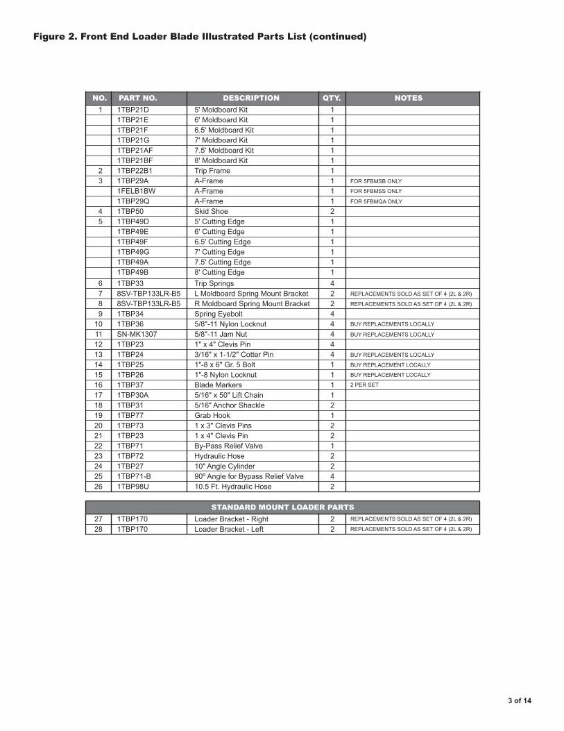
Figure 2. Front End Loader Blade Illustrated Parts List (continued)
NO.
STANDARD MOUNT LOADER PARTS
PART NO. DESCRIPTION QTY. NOTES1
23
45
11111111112111111
BUY REPLACEMENTS LOCALLY
REPLACEMENTS SOLD AS SET OF 4 (2L & 2R)
FOR 5FBMSB ONLY
FOR 5FBMSS ONLY
FOR 5FBMQA ONLY
REPLACEMENTS SOLD AS SET OF 4 (2L & 2R)
REPLACEMENTS SOLD AS SET OF 4 (2L & 2R)
REPLACEMENTS SOLD AS SET OF 4 (2L & 2R)
BUY REPLACEMENTS LOCALLY
BUY REPLACEMENTS LOCALLY
BUY REPLACEMENT LOCALLY
BUY REPLACEMENT LOCALLY
2 PER SET
5' Moldboard Kit6' Moldboard Kit6.5' Moldboard Kit7' Moldboard Kit7.5' Moldboard Kit8' Moldboard KitTrip FrameA-FrameA-FrameA-FrameSkid Shoe5' Cutting Edge6' Cutting Edge6.5' Cutting Edge7' Cutting Edge7.5' Cutting Edge8' Cutting Edge
42244444111
Trip SpringsL Moldboard Spring Mount BracketR Moldboard Spring Mount BracketSpring Eyebolt5/8"-11 Nylon Locknut5/8"-11 Jam Nut1" x 4" Clevis Pin3/16" x 1-1/2" Cotter Pin1"-8 x 6" Gr. 5 Bolt1"-8 Nylon LocknutBlade Markers
6789
10111213141516
22
Loader Bracket - RightLoader Bracket - Left
2728
12122122
5/16" x 50" Lift Chain5/16" Anchor ShackleGrab Hook1 x 3" Clevis Pins1 x 4" Clevis PinBy-Pass Relief ValveHydraulic Hose10" Angle Cylinder
1718192021222324
1TBP21D1TBP21E1TBP21F1TBP21G1TBP21AF1TBP21BF1TBP22B11TBP29A1FELB1BW1TBP29Q1TBP501TBP49D1TBP49E1TBP49F1TBP49G1TBP49A1TBP49B1TBP338SV-TBP133LR-B58SV-TBP133LR-B51TBP341TBP36SN-MK13071TBP231TBP241TBP251TBP261TBP37
1TBP1701TBP170
42
90º Angle for Bypass Relief Valve10.5 Ft. Hydraulic Hose
2526
1TBP71-B1TBP98U
1TBP30A1TBP311TBP771TBP731TBP231TBP711TBP721TBP27
1.) Lay Moldboard on its face with ribbing up. To prevent paint damage place cardboard under top bend.
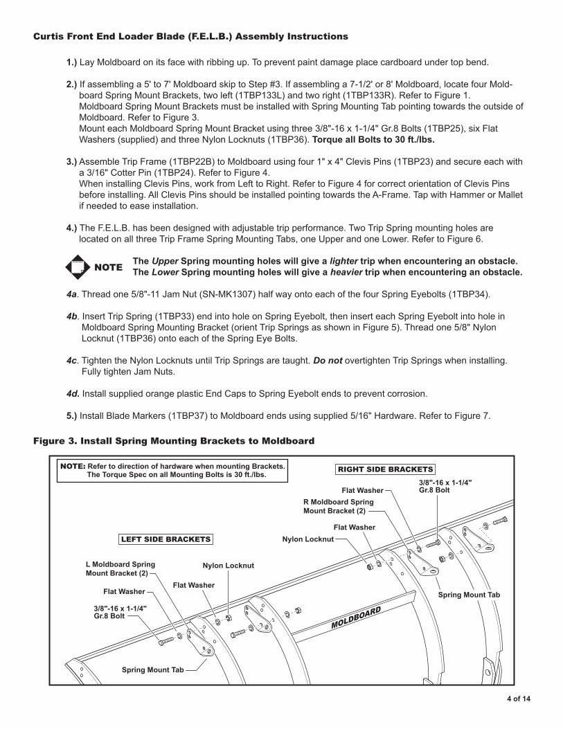
2.) If assembling a 5' to 7' Moldboard skip to Step #3. If assembling a 7-1/2' or 8' Moldboard, locate four Mold- board Spring Mount Brackets, two left (1TBP133L) and two right (1TBP133R). Refer to Figure 1. Moldboard Spring Mount Brackets must be installed with Spring Mounting Tab pointing towards the outside of Moldboard. Refer to Figure 3. Mount each Moldboard Spring Mount Bracket using three 3/8"-16 x 1-1/4" Gr.8 Bolts (1TBP25), six Flat Washers (supplied) and three Nylon Locknuts (1TBP36). Torque all Bolts to 30 ft./lbs.
3.) Assemble Trip Frame (1TBP22B) to Moldboard using four 1" x 4" Clevis Pins (1TBP23) and secure each with a 3/16" Cotter Pin (1TBP24). Refer to Figure 4. When installing Clevis Pins, work from Left to Right. Refer to Figure 4 for correct orientation of Clevis Pins before installing. All Clevis Pins should be installed pointing towards the A-Frame. Tap with Hammer or Mallet if needed to ease installation.
4.) The F.E.L.B. has been designed with adjustable trip performance. Two Trip Spring mounting holes are located on all three Trip Frame Spring Mounting Tabs, one Upper and one Lower. Refer to Figure 6.
The Upper Spring mounting holes will give a lighter trip when encountering an obstacle. The Lower Spring mounting holes will give a heavier trip when encountering an obstacle. 4a. Thread one 5/8"-11 Jam Nut (SN-MK1307) half way onto each of the four Spring Eyebolts (1TBP34).
4b. Insert Trip Spring (1TBP33) end into hole on Spring Eyebolt, then insert each Spring Eyebolt into hole in Moldboard Spring Mounting Bracket (orient Trip Springs as shown in Figure 5). Thread one 5/8" Nylon Locknut (1TBP36) onto each of the Spring Eye Bolts.
4c. Tighten the Nylon Locknuts until Trip Springs are taught. Do not overtighten Trip Springs when installing. Fully tighten Jam Nuts.
4d. Install supplied orange plastic End Caps to Spring Eyebolt ends to prevent corrosion.
5.) Install Blade Markers (1TBP37) to Moldboard ends using supplied 5/16" Hardware. Refer to Figure 7.
4 of 14
Curtis Front End Loader Blade (F.E.L.B.) Assembly Instructions
Figure 3. Install Spring Mounting Brackets to Moldboard
L Moldboard SpringMount Bracket (2)
R Moldboard SpringMount Bracket (2)
3/8"-16 x 1-1/4" Gr.8 Bolt
3/8"-16 x 1-1/4" Gr.8 Bolt
Flat Washer
Flat Washer
Flat Washer
Nylon Locknut
NOTE: Refer to direction of hardware when mounting Brackets. The Torque Spec on all Mounting Bolts is 30 ft./lbs.
Nylon LocknutFlat Washer
LEFT SIDE BRACKETS
RIGHT SIDE BRACKETS
MOLDBOARD
Spring Mount Tab
Spring Mount Tab
NOTE

5 of 14
Figure 4. Mount Trip Frame to Moldboard
Figure 5. Install Trip Springs
Tighten Locknuts on Eyebolts untilcorrect Spring tension is achievedA
BInstall
End Caps
End Cap
Install Clevis Pin and secure with Cotter Pin
Note orientation ofLeft and Right Clevis Pins
Trip Frame is attached to Moldboardwith 4 Clevis Pins in locations shown
12
34
TRIP FRAMELEFT SIDE TRIP FRAME
LEFT SIDEMOLDBOARD
Looking down on Trip Frame
1" x 4"Clevis Pin
Cotter Pin

6 of 14
Figure 6. Trip Spring Installation - Adjustable Trip Performance
Figure 7. Blade Marker Mounting
Use Lower four Holes for heavierPlow trip when striking an obstacle
Use Upper four Holes for lighterPlow trip when striking an obstacle
Trip Frame Spring Mounting Tabs on Trip Frame
TRIP FRAME FRONT VIEW
Supplied5/16" Bolts
Supplied5/16" Washers & Nuts
NOTE: Mounting is identical for both Blade Markers

Curtis Front End Loader Blade (F.E.L.B.) Assembly Instructions (continued)
7.) Locate both 10" Angle Cylinders (1TBP27) and mount one to each side of the A-Frame. The Angle Cylinders will be inserted into the A-Frame at the front through the slots, with the Hydraulic Port facing up and visible through the opening at the top of the A-Frame. Mount each Angle Cylinder to the A-Frame with a 1" x 3" Clevis Pin (1TBP73) and secure each Clevis Pin with a 3/16" x 1-1/2" Cotter Pin (1TBP24). Refer to Figure 8.
8.) Lift the A-Frame above the Trip Frame, and insert the A-frame and Angle Cylinders into the Trip Frame. Apply grease to the 1"-8 x 6" Gr.5 Center Bolt (1TBP25) and insert through the Trip Frame and A-Frame. Secure the Center Bolt with a 1" Nylon Lock Nut (1TBP26). Refer to Figure 9.
Do not over tighten the Nylon Lock Nut, the A-Frame must pivot freely.
9.) Swing A-Frame to Left or Right and align hole in Angle Cylinder Ram with the corresponding hole in Trip Frame. Install (1) 1" x 4" Clevis Pin (1TBP23) through Trip Frame and Angle Cylinder Ram. Secure Clevis Pin with (1) 3/16" x 1-1/2" Cotter Pin (1TBP24). Swing A-Frame to opposite side and repeat alignment and pinning procedure. Swing A-Frame back to the center.
It may be necessary to extend the Angle Cylinder Piston Rod 1-2" to make the connection to the Trip Frame. To do this, insert a long pin or ratchet handle through the Piston Rod and work the piston Rod side to side while pushing downward.
10.) Return the A-Frame to the center position after the Angle Cylinders are secured to the Moldboard. Using the A-Frame as a lever, grasp the A-Frame by the cross-brace and pull back, raising the Moldboard to a vertical position.
Figure 8. Mount Angle Cylinders to A-Frame
1" x 3"Clevis Pin
1" x 3"Clevis Pin
Angle Cylinders areinserted into slots inthe front of A-Frame
3/16" x 1-1/2"Cotter Pinsinstall frombelow
Hose Ports up
NOTE
NOTE
7 of 14

8 of 14
Figure 9. Mount A-Frame to Trip Frame
1" NylonLock Nut
1" x 6" BoltApply Grease
3/16" x 1-1/2"Cotter Pin
3/16" x 1-1/2"Cotter Pin
1" x 4" Clevis Pin
Swing A-Frame L&R
to
insert Pins
1" x 4" Clevis Pin
11.) Locate and install the two Hydraulic Hoses (1TBP72) to each side of the By-Pass Relief Valve and to the corresponding Ports on the Left and Right Angle Cylinders.
Do not use Teflon Tape on the Hydraulic Fittings as it may contaminate the Hydraulic System causing a malfunction. Use a high quality paste type thread sealant on all N.P.T. fittings.
Due to the large number of variations in tractor hydraulic systems and fittings, two hoses with 1/4" male NPT threads have been provided to connect between the tractor and By-Pass Valve, but fittings and quick connectors have not. Most skid steer loaders have extra lines which can be tied into. Some tractors have an auxillary valve that can be used, or an optional valve kit can be purchased from Curtis. The last option is to connect the lines from the loader tilt cylinders and tie them into the bypass block. Be sure to connect before the T-Fitting that connects the left and right tilt cylinders. If using this option the loader blade will need to be supported with Lift Chain provided. See Step 12 below. 12.) Attach Lift Chain (1TBP30A) to A-Frame assembly with 5/16" Anchor Shackle (1TBP31).
IMPORTANT
IMPORTANT

Figure 10. Install Hydraulic Hoses
Figure 11. F.E.L.B. with Skidsteer Reference View
Connect Hydraulic Hosesfrom L & R Angle Cylindersto By-Pass Relief Valve
Relief Valve
9 of 14

10 of 14
Mounting F.E.L.B. with Loader Attachment Brackets
1.) Center A-Frame (1TBP29A) in front of the Tractor. Position one or both Loader Brackets (1TBP170) to align with each of the Tractor Loader Arms, depending on width. Refer to Figure 12.
2.) Fully seat the tongue and groove cutouts of the L & R Loader Brackets into A-Frame Rear Cross Brace.
Position L & R Loader Brackets so that the outboard bracket bolt holes line up with slots in Rear A-Frame Cross-Brace. This may result in two of the same bracket on each Loader Arm depending on Loader Arm width.
3.) Verify 1/8" clearance on either side of Tractor Loader Arms. Attach the outboard L& R Loader Brackets to A-Frame Rear Cross Brace by bolting through the slots in the A-Frame. Use 1/2" x 1-3/4" Bolts in top of A-Frame (2 per bracket). Use 1-1/2" length Bolts in all other holes (3 per Bracket).
Install 1-1/2" Bolt through front of A-Frame Cross Brace first.
4.) Position inboard Brackets with a 1/8" clearance and clamp in place. Drill 9/16" holes into the A-Frame Cross- Brace using the holes in the Loader Brackets as guides. Bolt inboard Brackets to A-Frame Rear Cross Brace with 1/2" x 1-3/4" Bolts in the top of the A-Frame (2 per Bracket) and 1-1/2" length Bolts in all other holes. Torque all Loader Bracket Bolts to 98 ft./lbs.
• Loader Brackets L & R are to be bolted to the A-Frame in accordance with the I.D. and O.D. of Loader Arms. Tongue and Groove design allows installer to slide Brackets into position. Leave 1/8" clearance for Easy On/Easy Off.
• Due to Tractor Loader Arm variations, Dealer/Customer is to supply Attachment Pins. Curtis recommends a Grade 8 Bolt and Nylon Locknut of the proper length and diameter.
After 2 hours of use, all bolted assemblies on the F.E.L.B. should be rechecked for proper torque specifications and tightened as needed.
Figure 12. Mounting F.E.L.B. with Standard Mount Loader Brackets L & R
Tractor Arms
Tractor Arms
Standard MountLoader Brackets - Left and Right
Standard MountLoader Brackets - Left and Right
Center A-Frame in front of Tractor
Tractor Loader Arm widthdetermines whether one orboth Loader Brackets will beused on each side
Loader Brackets bolt through slots
A-Frame
CrossBrace
NOTE
NOTE
ADDITIONALNOTES
IMPORTANT

11 of 14
Figure 13. Loader Blade secured with Lift Chain
Lift Chain secured with Grab Hook
LOADER CROSS-BRACE
Attach Lift Chain to Loader • (If Loader Tilt Cylinders have been disconnected for Power Angle)
1.) Find a secure spot on the Loader Cross-Brace to wrap Lift Chain (1TBP31) around. The Chain should go over the Top of the Cross-Brace and wrap underneath. Refer to Figure 13 above. Be certain Chain will not pinch or damage any hydraulic lines or other parts of the Loader.
2.) Cut Chain to length and install supplied Grab Hook (1TBP77) to the Chain with Anchor Shackle (1TBP31) provided. Hook back onto the Chain.

12 of 14
Figure 15. John Deere Quick Attach Adaptor - Part Number: 5FBMQA
Figure 14. Skid Steer Adaptor - Part Number: 1FELB1BW

13 of 14
Optional Auxiliary By-Pass Control Valve (PN: 9PKFELBV)
• Installation of this Curtis Auxiliary Control Valve retains the Tractor/Loader's Bucket Cylinders for down pressure • The Curtis Auxiliary Control Valve is Universal in nature. • Carefully consider mounting location before proceeding. • Due to Tractor variations, Curtis only supplies Hoses and Fittings between the Angle Cylinders and Curtis By- Pass Relief Valve. All additional Hoses, Fittings and Couplings are Dealer/Customer supplied.
1.) Determine convenient location to mount Auxiliary Control Valve. If Loader is Quick Attach Style, consider mounting Valve to remain with Tractor/Loader when detached.
2.) Disconnect Pressure Supply Line from existing Tractor/Loader Valve.
3.) Route Tractor/Loader Pressure Supply Line to Inlet Port marked "IN" on Auxiliary Control Valve.
4.) Route a Dealer supplied Line from Outlet Port marked "OUT" on Auxiliary Control Valve to Pressure Port on existing Tractor/Loader Valve.
5.) Route two additional Dealer Supplied Hoses from Ports marked "A" and "B" on existing Tractor/Loader Valve down along Tractor/Loader Arms to corresponding "A" and "B" ports on Curtis By-Pass Relief Valve.
Curtis Auxiliary By-Pass Control Valve Port designations are for reference only.
6.) Route Curtis Supplied Angle Hoses from "C" and "D" Ports on Curtis By-Pass Relief Valve to Left and Right Angle Cylinders.
7.) Check all Hydraulic connections and test operation. Inspect for leaks.
Seal all N.P.T. (National Pipe Thread) connections with a Paste Type Thread Sealer (e.g. 3M, Great White) DO NOT use Teflon Tape. Teflon Tape may contaminate Hydraulic System and cause a malfunction.
IMPORTANT
Figure 16 . Hydraulic Routing Diagram
A
B
DC
To Control ValveRight Angle Function
To Control ValveLeft Angle Function
A B
IN
OUT
Tractor HydraulicsPressure Hose
To "B" Port onBy-Pass Relief Valve
To "A" Port onBy-Pass Relief Valve
Attach ControlLever Here
To TractorLoader Valve "IN"
SUPPLIED HOSE SUPPLIED HOSE
LeftAngle
Cylinder
RightAngle
Cylinder
Auxillary Loader Control Valve
Curtis By-Pass Relief Valve
NOTE
IMPORTANT
14 of 14
Notes:
LIMITED WARRANTYCurtis warrants that Products sold to Customer shall be free from defects in material andworkmanship under normal use and service for one (1) year from the date of shipment.
IN NO EVENT SHALL CURTIS BE LIABLE FOR LOSS OF PROFITS OR INCIDENTAL,INDIRECT, SPECIAL, CONSEQUENTIAL OR OTHER SIMILAR DAMAGES ARISING OUT OF
ANY SALE OF PRODUCT OR FROM DEFECTIVE PRODUCT.This limited warranty shall automatically terminate if any product has been improperly installed,
maintained or operated or used for a purpose for which it was not designed. The limited warrantydoes not cover Product which has been altered or parts which are expendable by their nature (e.g.
cutting edges, blade guides, springs, nuts, bolts, pins, hoses, etc.). This limited warranty alsodoes not cover any plows installed on vehicles not designed by the manufacturer for plowing or
not equipped with the manufacturer’s snowplow preparation package.In the event that a Product is defective, Curtis, at its option, will correct such defect at its expense
upon delivery of the Product to Curtis FOB, its Worcester, Massachusetts facility, or refund thatportion of the purchase price allocatable to the defective Product. The remedy contained in the
preceding sentence will be the sole and exclusive remedy against Curtis.
EXCEPT AS SPECIFICALLY PROVIDED IN THIS DOCUMENT, THERE ARE NO OTHERWARRANTIES EXPRESSED OR IMPLIED, INCLUDING BUT NOT LIMITED TO, ANY IMPLIED
WARRANTIES OF MERCHANTABILITY OF FITNESS FOR A PARTICULAR PURPOSE.
Curtis Industries Inc. LLC, 111 Higgins St., Worcester, MA 01606 TEL: (800) 343-7676 FAX: (508) 854-3377 For Parts and information visit us at www.Curtisindustries.netCurtis Industries Inc. LLC, reserves the right to change product design or specifications without notice or liability.
Curtis Snow Plows are protected by the following U.S. Patent Numbers: 6,145,222 and 6,209,231 Licensed under U.S. Patent Number 5,568,694 & Canadian Patent Number 2,137,853.Other patents pending.
Curtis Front End Loader Blade (F.E.L.B.) Storage Instructions
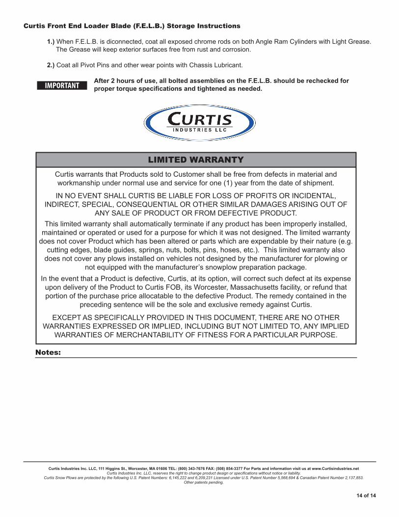
1.) When F.E.L.B. is diconnected, coat all exposed chrome rods on both Angle Ram Cylinders with Light Grease. The Grease will keep exterior surfaces free from rust and corrosion.
2.) Coat all Pivot Pins and other wear points with Chassis Lubricant.
After 2 hours of use, all bolted assemblies on the F.E.L.B. should be rechecked for proper torque specifications and tightened as needed.IMPORTANT