ft app gauges - ftdichip.com · ft_app_wrcocmd_buffer(phost,color_rgb(255,255,255)); a text...
TRANSCRIPT

Use of FTDI devices in life support and/or safety applications is entirely at the user’s risk, and the user agrees to defend, indemnify and hold FTDI harmless from any and all damages, claims, suits
or expense resulting from such use.
Future Technology Devices International Limited (FTDI) Unit 1, 2 Seaward Place, Glasgow G41 1HH, United Kingdom Tel.: +44 (0) 141 429 2777 Fax: + 44 (0) 141 429 2758
Web Site: http://ftdichip.com
Copyright © 2014 Future Technology Devices International Limited
APPLICATION NOTE
AN_263
FT_App_Gauges
Version 1.2
Document Reference No.: FT_000908
Issue Date: 2014-06-30
This document is to introduce the Gauges Demo Application. The objective of the Demo Application is to enable users to become familiar with the usage of the FT800, the design flow, and display list used to design the desired user interface or visual effect

Application Note
AN_263 FT_App_Gauges Version 1.2
Document Reference No.: FT_000908 Clearance No.: FTDI# 358
2 Copyright © 2014 Future Technology Devices International Limited
Table of Contents 1 Introduction ................................................................................................................ 3
1.1 Overview .............................................................................................................. 3
1.2 Scope .................................................................................................................. 3
2 Display Requirements ................................................................................................... 4
2.1 BackGround .......................................................................................................... 4
2.2 Analogue Gauges .................................................................................................. 4
2.3 Numeric Gauges .................................................................................................... 4
3 Design Flow ................................................................................................................. 5
3.1 Gauges Flowchart .................................................................................................. 6
4 Description of the Functional Blocks ................................................................................ 8
4.1 System Initialisation .............................................................................................. 8
4.2 Info() ................................................................................................................... 9
4.3 Loading the Font ................................................................................................. 11
4.4 Creating the Basic Gauge ..................................................................................... 11
4.5 Updating the Display ............................................................................................ 12
4.5.1 FT801 Display .............................................................................................. 13
5 Operation .................................................................................................................. 14
6 Contact Information ................................................................................................... 15
Appendix A– References .................................................................................................... 16
6.1 Document References .......................................................................................... 16
6.2 Acronyms and Abbreviations ................................................................................. 16
Appendix B – List of Tables & Figures .................................................................................. 17
6.3 List of Figures ..................................................................................................... 17
Appendix C– Revision History ............................................................................................. 18

Application Note
AN_263 FT_App_Gauges Version 1.2
Document Reference No.: FT_000908 Clearance No.: FTDI# 358
3 Copyright © 2014 Future Technology Devices International Limited
1 Introduction
This application demonstrates interactive gauges using rectangles, lines and custom fonts for the
numeric display offering a display with 2 digit precision on an FT80x platform.
On WQVGA displays, two gauges are used for demonstration purposes. One gauge displays
randomly generated data while the other displays resistance based on how firmly the touch screen
is pressed.
On QVGA displays only one gauge is used to display resistance, based on how firmly the touch
screen is pressed.
1.1 Overview
The application will be useful to understand the FT800 command sets for custom fonts, and FT800
primitives for lines and rectangles.
The application note should be read in conjunction with the source cod, which can be found in
section 4 and at http://www.ftdichip.com/Support/SoftwareExamples/FT800_Projects.htm.
1.2 Scope
This document can be used as a guide by designers to develop GUI applications by using an
FT80x with any MCU via SPI or I2C. Note detailed documentation is available on
www.ftdichip.com/EVE.htm including:
FT800 datasheet
FT801 datasheet Programming Guide covering EVE command language
AN_240 FT800 From the Ground Up
AN_245 VM800CB_SampleApp_PC_Introduction - covering detailed design flow with a PC
and USB to SPI bridge cable
AN_246 VM800CB_SampleApp_Arduino_Introduction – covering detailed design flow in an
Arduino platform
AN_252 FT800 Audio Primer

Application Note
AN_263 FT_App_Gauges Version 1.2
Document Reference No.: FT_000908 Clearance No.: FTDI# 358
4 Copyright © 2014 Future Technology Devices International Limited
2 Display Requirements
This section describes some of the key components of the design.
2.1 BackGround
The display background is created to show a plain dark grey that the gauges will contrast against.
2.2 Analogue Gauges
The analogue gauges will display a random value or the resistance in relation to the touch
pressure on the screen. The scale markings are coloured green for 0 to 60, yellow for 60 to 80 and
red for 80 to 90.
2.3 Numeric Gauges
Numeric gauges will display the same value as the analogue gauges but as decimal numbers using the custom font loaded at the start of the application.
Application Note
AN_263 FT_App_Gauges Version 1.2
Document Reference No.: FT_000908 Clearance No.: FTDI# 358
5 Copyright © 2014 Future Technology Devices International Limited
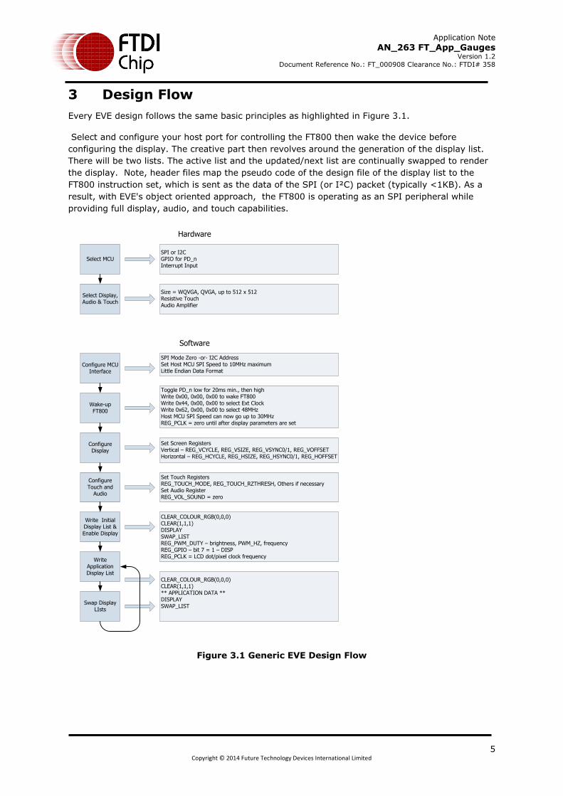
3 Design Flow
Every EVE design follows the same basic principles as highlighted in Figure 3.1.
Select and configure your host port for controlling the FT800 then wake the device before
configuring the display. The creative part then revolves around the generation of the display list.
There will be two lists. The active list and the updated/next list are continually swapped to render
the display. Note, header files map the pseudo code of the design file of the display list to the
FT800 instruction set, which is sent as the data of the SPI (or I²C) packet (typically <1KB). As a
result, with EVE's object oriented approach, the FT800 is operating as an SPI peripheral while
providing full display, audio, and touch capabilities.
Select Display, Audio & Touch
Select MCU
Configure MCU Interface
Wake-up FT800
Configure Display
Configure Touch and
Audio
Write Initial Display List & Enable Display
Write Application Display List
Swap Display LIsts
SPI or I2CGPIO for PD_nInterrupt Input
Size = WQVGA, QVGA, up to 512 x 512Resistive TouchAudio Amplifier
SPI Mode Zero -or- I2C AddressSet Host MCU SPI Speed to 10MHz maximumLittle Endian Data Format
Toggle PD_n low for 20ms min., then highWrite 0x00, 0x00, 0x00 to wake FT800Write 0x44, 0x00, 0x00 to select Ext ClockWrite 0x62, 0x00, 0x00 to select 48MHzHost MCU SPI Speed can now go up to 30MHzREG_PCLK = zero until after display parameters are set
Set Screen RegistersVertical – REG_VCYCLE, REG_VSIZE, REG_VSYNC0/1, REG_VOFFSETHorizontal – REG_HCYCLE, REG_HSIZE, REG_HSYNC0/1, REG_HOFFSET
Set Touch Registers REG_TOUCH_MODE, REG_TOUCH_RZTHRESH, Others if necessarySet Audio RegisterREG_VOL_SOUND = zero
CLEAR_COLOUR_RGB(0,0,0)CLEAR(1,1,1)DISPLAYSWAP_LISTREG_PWM_DUTY – brightness, PWM_HZ, frequencyREG_GPIO – bit 7 = 1 – DISPREG_PCLK = LCD dot/pixel clock frequency
CLEAR_COLOUR_RGB(0,0,0)CLEAR(1,1,1)** APPLICATION DATA **DISPLAYSWAP_LIST
Hardware
Software
Figure 3.1 Generic EVE Design Flow
Application Note
AN_263 FT_App_Gauges Version 1.2
Document Reference No.: FT_000908 Clearance No.: FTDI# 358
6 Copyright © 2014 Future Technology Devices International Limited
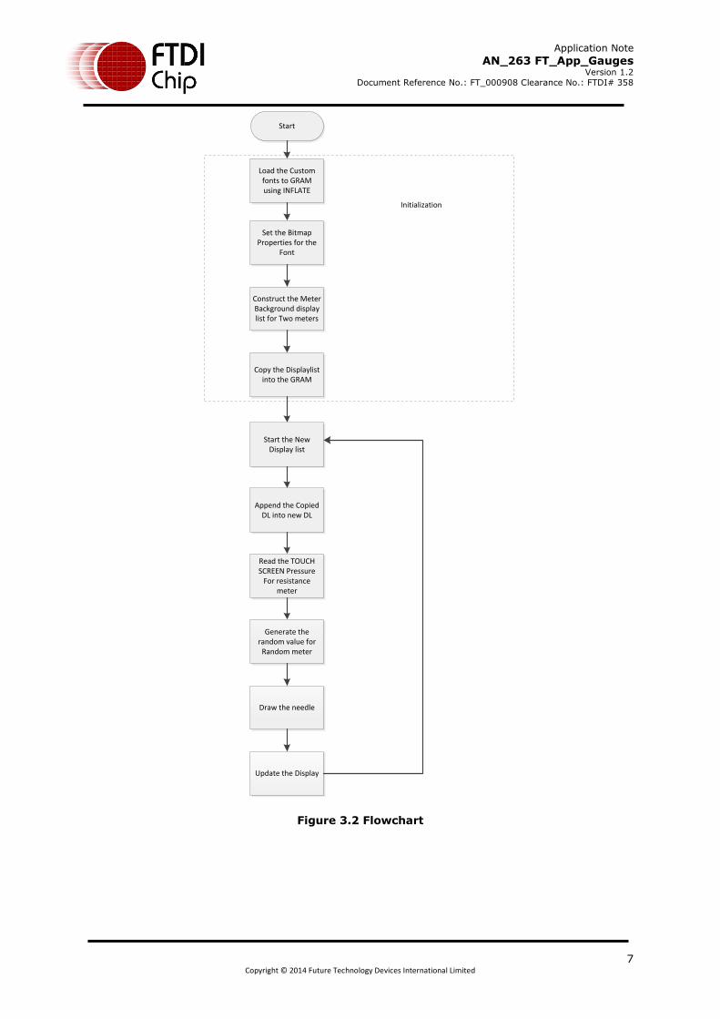
3.1 Gauges Flowchart
The flow chart below is specific to the Gauges application. Custom fonts are loaded into the
Graphics RAM for use with the numeric display. The display background is then generated for
display. Touch pressure is read and converted to a display value on one gauge while the other
uses a randomly generated number. The program then operates in a loop to update the display
list.
Application Note
AN_263 FT_App_Gauges Version 1.2
Document Reference No.: FT_000908 Clearance No.: FTDI# 358
7 Copyright © 2014 Future Technology Devices International Limited
Start
Set the Bitmap Properties for the
Font
Construct the Meter Background display list for Two meters
Copy the Displaylist into the GRAM
Load the Custom fonts to GRAM using INFLATE
Initialization
Start the New Display list
Append the Copied DL into new DL
Read the TOUCH SCREEN Pressure
For resistance meter
Generate the random value for
Random meter
Draw the needle
Update the Display
Figure 3.2 Flowchart
Application Note
AN_263 FT_App_Gauges Version 1.2
Document Reference No.: FT_000908 Clearance No.: FTDI# 358
8 Copyright © 2014 Future Technology Devices International Limited
4 Description of the Functional Blocks
4.1 System Initialisation
Configuration of the SPI master port is unique to each controller – different registers etc, but all
will require data to be sent Most Significant Bit (MSB) first with a little endian format.
The function labelled Ft_BootupConfig in this project is generic to all applications and will start by
toggling the FT800 PD# pin to perform a power cycle.
/* Do a power cycle for safer side */ Ft_Gpu_Hal_Powercycle(phost,FT_TRUE); Ft_Gpu_Hal_Rd16(phost,RAM_G);
/* Set the clk to external clock */ Ft_Gpu_HostCommand(phost,FT_GPU_EXTERNAL_OSC); Ft_Gpu_Hal_Sleep(10); /* Switch PLL output to 48MHz */ Ft_Gpu_HostCommand(phost,FT_GPU_PLL_48M); Ft_Gpu_Hal_Sleep(10); /* Do a core reset for safer side */ Ft_Gpu_HostCommand(phost,FT_GPU_CORE_RESET); /* Access address 0 to wake up the FT800 */ Ft_Gpu_HostCommand(phost,FT_GPU_ACTIVE_M);
The internal PLL is then given a prompt by setting the clock register and PLL to 48 MHz.
Note 36MHz is possible but will have a knock on effect for the display timing parameters.
A software reset of the core is performed followed by a dummy read to address 0 to complete the
wake up sequence.
The FT800 GPIO lines are also controlled by writing to registers:
Ft_Gpu_Hal_Wr8(phost, REG_GPIO_DIR,0x80 | Ft_Gpu_Hal_Rd8(phost,REG_GPIO_DIR)); Ft_Gpu_Hal_Wr8(phost, REG_GPIO,0x080 | Ft_Gpu_Hal_Rd8(phost,REG_GPIO));
And these allow the display to be enabled.
To confirm the FT800 is awake and ready to start accepting display list information the identity
register is read in a loop until it reports back 0x7C. It will always be 0x7C if everything is awake
and functioning correctly.
ft_uint8_t chipid; //Read Register ID to check if FT800 is ready. chipid = Ft_Gpu_Hal_Rd8(phost, REG_ID); while(chipid != 0x7C) chipid = Ft_Gpu_Hal_Rd8(phost, REG_ID);
Once the FT800 is awake the display may be configured through 13 register writes according to its
resolution. Resolution and timing data should be available in the display datasheet.
Application Note
AN_263 FT_App_Gauges Version 1.2
Document Reference No.: FT_000908 Clearance No.: FTDI# 358
9 Copyright © 2014 Future Technology Devices International Limited
Ft_Gpu_Hal_Wr16(phost, REG_HCYCLE, FT_DispHCycle); Ft_Gpu_Hal_Wr16(phost, REG_HOFFSET, FT_DispHOffset); Ft_Gpu_Hal_Wr16(phost, REG_HSYNC0, FT_DispHSync0); Ft_Gpu_Hal_Wr16(phost, REG_HSYNC1, FT_DispHSync1); Ft_Gpu_Hal_Wr16(phost, REG_VCYCLE, FT_DispVCycle); Ft_Gpu_Hal_Wr16(phost, REG_VOFFSET, FT_DispVOffset); Ft_Gpu_Hal_Wr16(phost, REG_VSYNC0, FT_DispVSync0); Ft_Gpu_Hal_Wr16(phost, REG_VSYNC1, FT_DispVSync1); Ft_Gpu_Hal_Wr8(phost, REG_SWIZZLE, FT_DispSwizzle); Ft_Gpu_Hal_Wr8(phost, REG_PCLK_POL, FT_DispPCLKPol); Ft_Gpu_Hal_Wr8(phost, REG_PCLK,FT_DispPCLK);//after this display is visible on the LCD Ft_Gpu_Hal_Wr16(phost, REG_HSIZE, FT_DispWidth); Ft_Gpu_Hal_Wr16(phost, REG_VSIZE, FT_DispHeight);
To complete the configuration the touch controller should also be calibrated
/* Touch configuration - configure the resistance value to 1200 - this value is specific to customer requirement and derived by experiment */ Ft_Gpu_Hal_Wr16(phost, REG_TOUCH_RZTHRESH,1200); Ft_Gpu_Hal_Wr8(phost, REG_GPIO_DIR,0xff); Ft_Gpu_Hal_Wr8(phost, REG_GPIO,0x0ff);
An optional step is present in this code to clear the screen so that no artefacts from bootup are
displayed.
/*It is optional to clear the screen here*/ Ft_Gpu_Hal_WrMem(phost, RAM_DL,(ft_uint8_t
*)FT_DLCODE_BOOTUP,sizeof(FT_DLCODE_BOOTUP)); Ft_Gpu_Hal_Wr8(phost, REG_DLSWAP,DLSWAP_FRAME);
4.2 Info()
This is a largely informational section of code and it starts by synchronising the physical xy
coordinates of the displays touch layer with the displays visual layer.
A display list is started and cleared:
Ft_Gpu_CoCmd_Dlstart(phost); Ft_App_WrCoCmd_Buffer(phost,CLEAR(1,1,1)); Ft_App_WrCoCmd_Buffer(phost,COLOR_RGB(255,255,255)); A text instruction is printed on the display followed by the call to the internal calibrate function:
Ft_Gpu_CoCmd_Text(phost,FT_DispWidth/2,FT_DispHeight/2,26,OPT_CENTERX|OPT_CENTERY,"Please tap on a dot");
Ft_Gpu_CoCmd_Calibrate(phost,0); The display list is then terminated and swapped to allow the changes to take effect.
Ft_App_WrCoCmd_Buffer(phost,DISPLAY()); Ft_Gpu_CoCmd_Swap(phost); Ft_App_Flush_Co_Buffer(phost); Ft_Gpu_Hal_WaitCmdfifo_empty(phost);
Next up in the Info() function is the FTDI logo playback:

Application Note
AN_263 FT_App_Gauges Version 1.2
Document Reference No.: FT_000908 Clearance No.: FTDI# 358
10 Copyright © 2014 Future Technology Devices International Limited
Ft_Gpu_CoCmd_Logo(phost); Ft_App_Flush_Co_Buffer(phost); Ft_Gpu_Hal_WaitCmdfifo_empty(phost); while(0!=Ft_Gpu_Hal_Rd16(phost,REG_CMD_READ)); dloffset = Ft_Gpu_Hal_Rd16(phost,REG_CMD_DL); dloffset -=4; Ft_Gpu_Hal_WrCmd32(phost,CMD_MEMCPY); Ft_Gpu_Hal_WrCmd32(phost,100000L); Ft_Gpu_Hal_WrCmd32(phost,RAM_DL); Ft_Gpu_Hal_WrCmd32(phost,dloffset); play_setup();
A composite image with the logo and a start arrow is then displayed to allow the user to start the
main application
do { Ft_Gpu_CoCmd_Dlstart(phost); Ft_Gpu_CoCmd_Append(phost,100000L,dloffset); Ft_App_WrCoCmd_Buffer(phost,BITMAP_TRANSFORM_A(256)); Ft_App_WrCoCmd_Buffer(phost,BITMAP_TRANSFORM_A(256)); Ft_App_WrCoCmd_Buffer(phost,BITMAP_TRANSFORM_B(0)); Ft_App_WrCoCmd_Buffer(phost,BITMAP_TRANSFORM_C(0)); Ft_App_WrCoCmd_Buffer(phost,BITMAP_TRANSFORM_D(0)); Ft_App_WrCoCmd_Buffer(phost,BITMAP_TRANSFORM_E(256)); Ft_App_WrCoCmd_Buffer(phost,BITMAP_TRANSFORM_F(0)); Ft_App_WrCoCmd_Buffer(phost,SAVE_CONTEXT()); Ft_App_WrCoCmd_Buffer(phost,COLOR_RGB(219,180,150)); Ft_App_WrCoCmd_Buffer(phost,COLOR_A(220)); Ft_App_WrCoCmd_Buffer(phost,BEGIN(EDGE_STRIP_A)); Ft_App_WrCoCmd_Buffer(phost,VERTEX2F(0,FT_DispHeight*16)); Ft_App_WrCoCmd_Buffer(phost,VERTEX2F(FT_DispWidth*16,FT_DispHeight*16)); Ft_App_WrCoCmd_Buffer(phost,COLOR_A(255)); Ft_App_WrCoCmd_Buffer(phost,RESTORE_CONTEXT()); Ft_App_WrCoCmd_Buffer(phost,COLOR_RGB(0,0,0)); // INFORMATION Ft_Gpu_CoCmd_Text(phost,FT_DispWidth/2,20,28,OPT_CENTERX|OPT_CENTERY,info[0]); Ft_Gpu_CoCmd_Text(phost,FT_DispWidth/2,60,26,OPT_CENTERX|OPT_CENTERY,info[1]); Ft_Gpu_CoCmd_Text(phost,FT_DispWidth/2,90,26,OPT_CENTERX|OPT_CENTERY,info[2]); Ft_Gpu_CoCmd_Text(phost,FT_DispWidth/2,120,26,OPT_CENTERX|OPT_CENTERY,info[3]); Ft_Gpu_CoCmd_Text(phost,FT_DispWidth/2,FT_DispHeight-30,26,OPT_CENTERX|OPT_CENTERY,"Click to play"); if(sk!='P') Ft_App_WrCoCmd_Buffer(phost,COLOR_RGB(255,255,255)); else Ft_App_WrCoCmd_Buffer(phost,COLOR_RGB(100,100,100)); Ft_App_WrCoCmd_Buffer(phost,BEGIN(FTPOINTS)); Ft_App_WrCoCmd_Buffer(phost,POINT_SIZE(20*16)); Ft_App_WrCoCmd_Buffer(phost,TAG('P')); Ft_App_WrCoCmd_Buffer(phost,VERTEX2F((FT_DispWidth/2)*16,(FT_DispHeight-60)*16)); Ft_App_WrCoCmd_Buffer(phost,COLOR_RGB(180,35,35)); Ft_App_WrCoCmd_Buffer(phost,BEGIN(BITMAPS)); Ft_App_WrCoCmd_Buffer(phost,VERTEX2II((FT_DispWidth/2)-14,(FT_DispHeight-75),14,0)); Ft_App_WrCoCmd_Buffer(phost,DISPLAY()); Ft_Gpu_CoCmd_Swap(phost); Ft_App_Flush_Co_Buffer(phost); Ft_Gpu_Hal_WaitCmdfifo_empty(phost); }while(Read_Keys()!='P');

Application Note
AN_263 FT_App_Gauges Version 1.2
Document Reference No.: FT_000908 Clearance No.: FTDI# 358
11 Copyright © 2014 Future Technology Devices International Limited
4.3 Loading the Font
The font table is hard coded in the application as an array labelled “digits”. This array is loaded
into graphics RAM at the start of the “Gauges” function with the CMD_INFLATE command:
Ft_Gpu_CoCmd_MemSet(phost,0,0,10*1024); Ft_App_Flush_Co_Buffer(phost); Ft_Gpu_Hal_WaitCmdfifo_empty(phost); Ft_Gpu_Hal_WrCmd32(phost,CMD_INFLATE); Ft_Gpu_Hal_WrCmd32(phost,0); WRITE2CMD(digits);
The first 32 Characters are unwanted so based on the width and height of the font the bitmap
source is skipped.
Ft_Gpu_CoCmd_Dlstart(phost); Ft_Gpu_CoCmd_SetFont(phost,13,0); Ft_App_WrCoCmd_Buffer(phost,BITMAP_HANDLE(13)); Ft_App_WrCoCmd_Buffer(phost,BITMAP_SOURCE(144 - (32L*(54/2)*87))); Ft_App_WrCoCmd_Buffer(phost,BITMAP_LAYOUT(L4, 54/2,87)); Ft_App_WrCoCmd_Buffer(phost,BITMAP_SIZE(NEAREST, BORDER, BORDER, 54, 87)); Ft_App_WrCoCmd_Buffer(phost,DISPLAY()); Ft_Gpu_CoCmd_Swap(phost); Ft_App_Flush_Co_Buffer(phost); Ft_Gpu_Hal_WaitCmdfifo_empty(phost);
Note: After these configurations are set, swap the display list and flush into the J1 Memory. Wait
for J1 Idle by using REG_CMD_WRITE and REG_CMD_READ registers
4.4 Creating the Basic Gauge
Active areas are cut in the background for each gauge with the scissors function. Each gauge
image is static, but the needle is continually updated.
Ft_Gpu_CoCmd_Dlstart(phost); Ft_App_WrCoCmd_Buffer(phost,CLEAR_COLOR_RGB(55,55,55)); Ft_App_WrCoCmd_Buffer(phost,CLEAR(1,1,1)); Ft_App_WrCoCmd_Buffer(phost,CLEAR_COLOR_RGB(0,0,0)); y = 10; for(z=0;z<(FT_DispWidth/w);z++) { ox = 240*z; Ft_App_WrCoCmd_Buffer(phost,SCISSOR_XY(ox+dt,y)); Ft_App_WrCoCmd_Buffer(phost,SCISSOR_SIZE(w,h)); Ft_App_WrCoCmd_Buffer(phost,CLEAR(1,1,1)); Coloured lines of different width mark the gauge scale.The “cs” function is used to define the colour in a separate function. Ft_App_WrCoCmd_Buffer(phost,BEGIN(LINES)); Ft_App_WrCoCmd_Buffer(phost,LINE_WIDTH(10)); for (bi = 0; bi < 81; bi += 10) { cs(bi); for ( i = 2; i < 10; i += 2) {

Application Note
AN_263 FT_App_Gauges Version 1.2
Document Reference No.: FT_000908 Clearance No.: FTDI# 358
12 Copyright © 2014 Future Technology Devices International Limited
a = da(bi + i); polar(220, a); polar(240, a); } } Ft_App_WrCoCmd_Buffer(phost,LINE_WIDTH(16)); for (i = 0; i < 91; i += 10) { cs(i); a = da(i); polar(220, a); polar(250, a); } White text to explain the gauge function is also applied. Ft_App_WrCoCmd_Buffer(phost,COLOR_RGB(255,255,255)); for (i = 0; i < 91; i += 10) { a = da(i); polarxy(260, a, &tx, &ty); Ft_Gpu_CoCmd_Number(phost,tx >> 4, ty >> 4,26,OPT_CENTER, i); } ox = (FT_DispWidth/(2*noofch))+(z*(FT_DispWidth/2)); if(z==1)Ft_Gpu_CoCmd_Text(phost,ox,h-10,28,OPT_CENTERX,"Random"); if(z==0)Ft_Gpu_CoCmd_Text(phost,ox,h-10,28,OPT_CENTERX,"Resistance"); }
4.5 Updating the Display
Updating the gauge displaying “random” data just uses the c code random function.
{ int d = (tgt - rval) / 16; rval += d; if (ft_random(60) == 0) tgt = ft_random(9000L); val = rval; }
The resistance function relies on reading the touch register REG_TOUCH_RZ which stores the
resistance change when the display is touched.
val = Ft_Gpu_Hal_Rd16(phost,REG_TOUCH_RZ); val = 10*min(899,val);
Both the graphical and numerical displays are updated.
Ft_App_WrCoCmd_Buffer(phost,SCISSOR_XY(ox+dt,10)); Ft_App_WrCoCmd_Buffer(phost,SCISSOR_SIZE(w,120)); Ft_App_WrCoCmd_Buffer(phost,COLOR_RGB(255,255,255)); Ft_App_WrCoCmd_Buffer(phost,BEGIN(LINES)); Ft_App_WrCoCmd_Buffer(phost,LINE_WIDTH(10)); th = (val - 4500L) * 32768L / 36000L; for (o = -5; o < 6; o++) {
Application Note
AN_263 FT_App_Gauges Version 1.2
Document Reference No.: FT_000908 Clearance No.: FTDI# 358
13 Copyright © 2014 Future Technology Devices International Limited
polar(170, th + (o << 5)); polar(235, th); } Ft_App_WrCoCmd_Buffer(phost,SCISSOR_XY(ox+dt,y)); Ft_App_WrCoCmd_Buffer(phost,SCISSOR_SIZE(w,(ft_uint16_t)(FT_DispHeight*0.36))); Ft_App_WrCoCmd_Buffer(phost,CLEAR(1,1,1)); Ft_App_WrCoCmd_Buffer(phost,COLOR_RGB(255,0,0)); Ft_Gpu_CoCmd_Number(phost,ox+dt+10,160,13,2,val/100); Ft_Gpu_CoCmd_Text(phost,ox+dt+96,160,13,0,"."); Ft_Gpu_CoCmd_Number(phost,ox+dt+106,160,13,2,val%100); } Ft_App_WrCoCmd_Buffer(phost,DISPLAY()); Ft_Gpu_CoCmd_Swap(phost); Ft_App_Flush_Co_Buffer(phost); Ft_Gpu_Hal_WaitCmdfifo_empty(phost);
4.5.1 FT801 Display
The FT801 capacitive display uses a different (capacitive) display touch controller compared to the
FT800 resistive controller.
As there is no resistance measurement on a capacitive display the program is altered to show the
X coordinate of the touch point. To enable this alternative display in the sample program open the
Platform.h file and look for:
#define FT_801_ENABLE
By default this is undefined (FT800 mode). To switch to the FT801 mode ensure this line is
defined. After making the change, rebuild and run the application.
Application Note
AN_263 FT_App_Gauges Version 1.2
Document Reference No.: FT_000908 Clearance No.: FTDI# 358
14 Copyright © 2014 Future Technology Devices International Limited
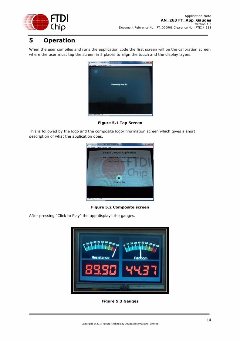
5 Operation
When the user compiles and runs the application code the first screen will be the calibration screen
where the user must tap the screen in 3 places to align the touch and the display layers.
Figure 5.1 Tap Screen
This is followed by the logo and the composite logo/information screen which gives a short
description of what the application does.
Figure 5.2 Composite screen
After pressing “Click to Play” the app displays the gauges.
Figure 5.3 Gauges
Application Note
AN_263 FT_App_Gauges Version 1.2
Document Reference No.: FT_000908 Clearance No.: FTDI# 358
15 Copyright © 2014 Future Technology Devices International Limited
6 Contact Information
Head Office – Glasgow, UK
Future Technology Devices International Limited Unit 1, 2 Seaward Place, Centurion Business Park Glasgow G41 1HH United Kingdom Tel: +44 (0) 141 429 2777 Fax: +44 (0) 141 429 2758 E-mail (Sales) [email protected] E-mail (Support) [email protected] E-mail (General Enquiries) [email protected] Branch Office – Taipei, Taiwan
Future Technology Devices International Limited (Taiwan) 2F, No. 516, Sec. 1, NeiHu Road Taipei 114 Taiwan , R.O.C. Tel: +886 (0) 2 8791 3570 Fax: +886 (0) 2 8791 3576 E-mail (Sales) [email protected] E-mail (Support) [email protected] E-mail (General Enquiries) [email protected]
Branch Office – Tigard, Oregon, USA
Future Technology Devices International Limited (USA) 7130 SW Fir Loop Tigard, OR 97223-8160 USA Tel: +1 (503) 547 0988 Fax: +1 (503) 547 0987 E-Mail (Sales) [email protected] E-Mail (Support) [email protected] E-Mail (General Enquiries) [email protected] Branch Office – Shanghai, China
Future Technology Devices International Limited (China) Room 1103, No. 666 West Huaihai Road, Shanghai, 200052 China Tel: +86 21 62351596 Fax: +86 21 62351595 E-mail (Sales) [email protected] E-mail (Support) [email protected] E-mail (General Enquiries) [email protected]
Web Site
http://ftdichip.com
Distributor and Sales Representatives
Please visit the Sales Network page of the FTDI Web site for the contact details of our distributor(s) and sales
representative(s) in your country.
System and equipment manufacturers and designers are responsible to ensure that their systems, and any Future Technology
Devices International Ltd (FTDI) devices incorporated in their systems, meet all applicable safety, regulatory and system-level
performance requirements. All application-related information in this document (including application descriptions, suggested
FTDI devices and other materials) is provided for reference only. While FTDI has taken care to assure it is accurate, this
information is subject to customer confirmation, and FTDI disclaims all liability for system designs and for any applications
assistance provided by FTDI. Use of FTDI devices in life support and/or safety applications is entirely at the user’s risk, and the
user agrees to defend, indemnify and hold harmless FTDI from any and all damages, claims, suits or expense resulting from
such use. This document is subject to change without notice. No freedom to use patents or other intellectual property rights is
implied by the publication of this document. Neither the whole nor any part of the information contained in, or the product
described in this document, may be adapted or reproduced in any material or electronic form without the prior written consent
of the copyright holder. Future Technology Devices International Ltd, Unit 1, 2 Seaward Place, Centurion Business Park,
Glasgow G41 1HH, United Kingdom. Scotland Registered Company Number: SC136640

Application Note
AN_263 FT_App_Gauges Version 1.2
Document Reference No.: FT_000908 Clearance No.: FTDI# 358
16 Copyright © 2014 Future Technology Devices International Limited
Appendix A– References
6.1 Document References
FT800 datasheet FT801 datasheet
Programming Guide covering EVE command language
AN_240 FT800 From the Ground Up
6.2 Acronyms and Abbreviations
Terms Description
Arduino Pro The open source platform variety based on ATMEL’s ATMEGA chipset
EVE Embedded Video Engine
SPI Serial Peripheral Interface
UI User Interface
USB Universal Serial Bus

Application Note
AN_263 FT_App_Gauges Version 1.2
Document Reference No.: FT_000908 Clearance No.: FTDI# 358
17 Copyright © 2014 Future Technology Devices International Limited
Appendix B – List of Tables & Figures
6.3 List of Figures
Figure 3.1 Generic EVE Design Flow ........................................................................... 5
Figure 3.2 Flowchart .................................................................................................. 7
Figure 5.1 Tap Screen .............................................................................................. 14
Figure 5.2 Composite screen .................................................................................... 14
Figure 5.3 Gauges .................................................................................................... 14

Application Note
AN_263 FT_App_Gauges Version 1.2
Document Reference No.: FT_000908 Clearance No.: FTDI# 358
18 Copyright © 2014 Future Technology Devices International Limited
Appendix C– Revision History
Document Title: AN_263 FT_App_Gauges
Document Reference No.: FT_000908
Clearance No.: FTDI# 358
Product Page: http://www.ftdichip.com/EVE.htm
Document Feedback: Send Feedback
Revision Changes Date
0.1 Initial draft release 2013-07-18
1.0 Version 1.0 updated wrt review comments 2013-08-21
1.1 Version 1.1 2012-11-01
1.2 Added section 4.5.1 2014-06-30