(full-frame and insert installations)
TRANSCRIPT

“Andersen” and all other marks where denoted are trademarks of Andersen Corporation. ©2021 Andersen Corporation. All rights reserved. 0005519 BI -00 03/22/2021
· Product Series - 100 Series · Product Type - All Windows
Flangeless Installation Instructions(Full-Frame and Insert Installations)
▶ For Full-Frame Window Installation, go to page 8. ▶ For Insert Window (Interior Installation), go to page 19. ▶ For Insert Window (Exterior Installation), go to page 33.
Parts Included:
Exterior Sill Extender Trim (optional)
Read these instructions before starting procedure. For additional information visit www.andersenwindows.com. For questions call 1-888-888-7020.Para obtener una versión en español de esta guía, visite el sitio www.andersenwindows.com
Head Expander (optional)
Window(single-hung shown in guide)
Screw Pack(s)
Installation Clip Pack(s)

Andersen Installation Sealant may be used at the sill as a structural attachment alternative to installation clips in flat sill insert applications. No sealant substitutions may be made. See interior and exterior insert instructions for details. Failure to use Andersen Installation Sealant may result in product or property damage.
20005519
Tools and Supplies Needed:
Flat sill structural attachment alternative requires Andersen Installation Sealant. Pre-order adequate amount of sealant prior to installation.
IMPORTANT
Protective Gloves
Putty Knife
Wood Block
J-rollerCombination Square
▶ Units in joined combinations must be individually supported to the rough opening.
▶ Do Not remove band or packing clips from windows until instructed.
▶ Anchoring screws must attach to framing members.
▶ Depending on unit size, windows may or may not come with installation clips applied.
*Specific to full frame installation.
Reciprocating Saw
Window Identification:
CasementSingle-Hung Gliding Fixed CombinationsAwningArch Single-Hung
Half Circle
NOTICE
Safety Glasses
Tape Measure
Drill / Driver Utility Knife
Rubber Mallet
Caulking Gun
Level
Sealant
Aluminum Coil Stock
Low Expanding Foam
Shims (waterproof)
Cleaning Cloth
Non-Abrasive Cleaner
FastenersFoam Backer Rod
*House Wrap Tape*Formable Self-Adhering Flashing
Andersen Installation Sealant (Flat sill structural attachment alternative)

Metal
INSTALLATION THROUGH THE JAMB ANCHORING REQUIREMENTS (select one)
Wood Screw
INSTALLATION GUSSET PLATE ANCHORING REQUIREMENTS (select one)
1-1/2"
Fastener MinimumShankSubstrate Steel Type/Coating SpacingMinimum Embedment to
Structural FramingGalvanized,
Zinc Chromate,*Stainless Steel,*Ceramic Coated
n/a
3 Full Threads
1-1/4"
Self-TappingMetal Screw
**Concrete Screw
#10
3/16"Masonry
MinimumHead
5/16"
5/16"
1-1/2"#8
Wood Screw #10Wood 5/16"
Every Hole
Every Hole
Fastener MinimumShankSubstrate Steel Type/Coating SpacingMinimum Embedment to
Structural FramingGalvanized,
Zinc Chromate,*Stainless Steel,*Ceramic Coated
n/a
3 Full Threads
1-1/4"
Self-TappingMetal Screw
**Concrete Screw
#8
3/16"
Wood
Metal
Masonry
Every Hole
MinimumHead
5/16"
5/16"
5/16"
Every Hole(except where minimum spacing cannot be met)
30005519
Use the correct fastener driver based on the selected fastener's head type. Size pilot and clearance holes based on the selected fastener's shank diameter as needed. * Use 300 series stainless steel or ceramic coated fasteners when fastening to treated lumber. ** Follow fastener manufacturer's anchoring recommendations (i.e. spacing, edge distance, hole depth, etc.)
INSTALLATION CLIP ANCHORING REQUIREMENTS (select one)
Wood Screw1-1/2"
#12
Fastener MinimumShankSubstrate Steel Type/Coating SpacingMinimum Embedment to
Structural FramingGalvanized,
Zinc Chromate,*Stainless Steel,*Ceramic Coated
n/a
3 Full Threads
1-1/4"
Self-TappingMetal Screw
**Concrete Screw
#8
3/16"
Wood
Metal
Masonry
MinimumHead
5/16"
5/16"
5/16"
Wood Screw #8Wood 5/16"1 per Clip
2 per Clip
1 per Clip
2 per Clip
FASTENER CHART

40005519
Draft
Draft
1
Procedure and Product Information
IMPORTANT
Important Safety and Product Informationfor Andersen® Windows and Doors
This is the Safety Alert Symbol used to alert you to potential injury hazards. Obey all safety messages that follow this symbol to avoid possible injury or death.
Signal Word and Consequence
Major Injury/DeathWARNINGCOULD
Result in: Minor InjuryCAUTIONCOULD
Result in:
Product or Property Damage
NOTICECOULDResult in:
· Leave this installation instruction with the home/building owner.· For additional support or help please go to: andersenwindows.com and visit our Help Center.· To configure installation instructions go to: andersenwindows.com/installation
Handling Installation
· Use caution when working at elevated heights and around window and door openings. Follow the manufacturers’ instructions for ladders and scaffolding. Failure to do so could result in injury or death.
· Support window or door in opening at all times until fully fastened. Failure to do so could result in window or door falling out causing injury, property or product damage.
· Windows and doors have small parts (e.g. hole plugs, operator spline caps, fasteners, etc.). Small parts if swallowed could pose a choking hazard to young children. Dispose of unused, loose, or easily removed small parts. Failure to do so could result in injury.
· Windows and doors can be heavy. Use safe lifting techniques and a reasonable number of people with enough strength to lift, carry, and install window and door products. Heavier windows and doors will require mechanical assistance. Failure to do so could result in injury, product or property damage.
· DO NOT lift or carry window or door by the exterior trim or extension jambs. Doing so could result in injury, product or property damage.
· Windows, doors, and installation components can have sharp edges. Wear protective equipment when handling. Failure to do so could result in injury.
· DO NOT drag, rock, cartwheel, or walk windows,doors, sash, or panels across the floor. Doing so couldresult in product or property damage.
Tools
· Follow manufacturers’ instructions for hand and power tools. Always wear safety glasses. Failure to do so could result in injury, product or property damage.
❚ Tools ❚ Handling ❚ Installation ❚ Sealing❚ Fastening❚ Finishing
Safety and Product Information Index❚ Glass❚ Protective Film ❚ Cleaning❚ Use/Operation❚ Joining ❚ Product Information
Read this Important Safety and Product Information completely before starting.
WARNING
WARNING WARNING
“Andersen” and all other marks where denoted are trademarks of Andersen Corporation. ©2021 Andersen Corporation. All rights reserved. SAFETY/PRODUCT INFORMATION 9144348 BG Revised 02/24/2021

50005519
Draft
Draft
2
NOTICE· Andersen head flashing and installation flanges DO NOT take the place of window and door flashing tape or liquid flashing. Window or door must be properly flashed and sealed with a material compatible sealant for protection against water and air infiltration. Failure to do so could result in product or property damage.
· DO NOT set window or door directly on installation flange. Doing so could affect product performance, and could result in product or property damage.
· DO NOT set window directly on sill plate. Elevate window with shims under the side jambs. Failure to do so could affect operation and product performance, and could result in product damage.
· Window or door must be properly shimmed. Failure to do so could affect operation and product performance, and could result in product damage.
· A continuous full perimeter interior seal between window or door frame and opening is required. Failure to do so will affect product performance, and could result in product or property damage.
· Protect window and door sills during installation and throughout construction. Failure to do so could result in product damage.
· DO NOT remove window or door packaging material until instructed to do so. Doing so could result in product damage.
Installation (Continued)
NOTICE· Use masonry screws when fastening directly into masonry or through a buck into masonry. Failure to do so could affect product performance, and could result in product or property damage.
· DO NOT over drive screws or nails. Doing so could result in product damage.
· Fasteners must be attached to a structural framing member. Failure to do so will reduce the structural performance to less than published values and could affect product performance, and could result in product or property damage.
Fastening
· Metal fasteners and components could corrode when exposed to preservative-treated or fire-retardant treated lumber. Use approved fasteners and components to fasten window or door. Failure to do so could cause a failure resulting in injury, product or property damage.
· Fastener must attach to a structural framing member with a 1-1/2" minimum fastener embedment. Failure to do so could result in injury, product or property damage.
· DO NOT remove screws that attach installation clips or gusset plates to window or door frames. Doing so could result in injury, product or property damage.
Sealing
NOTICE
CAUTION· Follow instructions of foam, sealant, and flashing manufacturers regarding safety, material application, compatibility, and periodic maintenance for continued weather resistance of their products. Failure to do so could result in injury, product or property damage.
FinishingNOTICE
· DO NOT stain or paint weatherstrip, vinyl, glass, or hardware. Doing so could result in product damage.
· Read and follow finish manufacturer's instructions and safety information. Failure to do so could result in product damage.
· DO NOT over load brush with stain or paint when finishing. Doing so could allow finish to wick between glass stop or grille, and glass.
WARNING
· Clean and prepare surfaces receiving sealant following sealant manufacturer's instructions. Failure to do so could result in water infiltration causing product or property damage.
· DO NOT use abrasive cleaners or solvents when cleaning Fibrex® material. Doing so could result in product damage. Go to andersenwindows.com for a list of recommended cleaners.

60005519
Draft
Draft
3
NOTICE
Glass
· Unless specifically ordered, Andersen windows are not equipped with safety glass, and if broken, could fragment causing injury. Many laws and building codes require safety glass in locations adjacent to or near doors. Andersen windows are available with safety glass that could reduce the likelihood of injury when broken. Information on safety glass is available from your local Andersen dealer.
· Tempered or laminated safety glass is not standard for windows and must be special ordered. Check local building codes for required locations. Failure to do so could result in injury, product or property damage.
· DO NOT place suction grips over filmseams on glass. Suction grips will not hold if placed over film seam to lift or move window or door. Window or door will fall and could result in injury, product or property damage.
· DO NOT remove any protective film near flammable materials. Static charge created when removing film can ignite flammable materials or cause a shock. Doing so could result in injury, product or property damage. See warning label on glass.
· Dispose of protective film immediately afterremoving. Failure to do so could pose a suffocationhazard to children.
NOTICE· DO NOT remove protective film from glass until afterconstruction is completed. Doing so could allow glass tobe damaged.
· Remove protective film from non-glass componentsimmediately after installation. Failure to do so couldresult in product damage.
NOTICE
Cleaning
Protective FilmFinishing (Continued)
· Finish all wood surfaces immediately afterinstallation. Unfinished wood will deteriorate, discolor,and could bow or split. Somesurfaces are hidden from view.
· Some products are shippedunassembled, and it may bemore convenient to finishwood surfaces for theseproducts prior to assembly and installation.
WARNING
WARNING
· Acid solutions used for cleaning masonry or concrete will damage all components of window or doors. Protect window or door and follow cleaning product manufacturer's instructions. If acid contacts window or door, wash all surfaces immediately with clean water.
· DO NOT use or apply solvents, abrasives, harsh chemicals or cleaners to window or door components. Doing so will result in product damage. For a list of recommended cleaners go to: andersenwindows.com
· DO NOT use metal razor blades toclean glass surface. Glass damagecould result.
· DO NOT apply any type of film to insulating glass. Doing so could cause thermal stress conditions and result in glass damage. Shading devices (e.g. insulated coverings, shutters, etc.) could also cause thermal stress and condensation causing deterioration of windows or doors.
· DO NOT use sealants on exterior or interior glass surface.
NOTICE

70005519
Draft
Draft
4
Joining
IMPORTANT· Buildings constructed prior to 1978 could contain lead paint which could be disturbed during window or door replacement. For more information on proper management of lead paint, go to: www.epa.gov/lead
· Instructions may not be right for all installations due to building design, construction materials, or methods used and/or building or site conditions. Consult a contractor or architect for recommendations.
· Installation flanges may need to be removed for some installations. (e.g. masonry, replacement), or where exterior finish is already applied (e.g. siding, brick veneer, stucco).
· Installation flange on the window or door alone will not properly flash and seal the window or door.
· DO NOT remove band, plastic ties, or packing clips from window or door until instructed.
· DO NOT remove performance (NFRC) label until after final inspection. Doing so could delay final inspection and sign-off by the code official.
· Check with your local building code official to identify and confirm compliance with local building code requirements.
· Contact local authorities or waste management company for proper recycling and disposal instructions for removed window or door.
· For cleaning instructions for window and door components go to: andersenwindows.com.
· During construction protect products from construction debris, harsh chemical such as brick wash, roof runoff, and cement/masonry which can cause damage to window and door products.
· Protective film is not present on all windows or doors. Protective film is not a substitute for masking.
· Remove protective film from glass within six (6) months ofinstallation and when temperature is above 32° F.
· Remove protective film by peeling from seam or corner. Use a plastic scraper to start if needed.
· Extension jambs can be factory applied on some windows or field applied prior to installation. DO NOT apply extension jambs prior to window or door installation that will be fastened with installation clips. Doing so could prevent access to installation clips for fastening.
· For extension jamb application refer to instructions included with part(s) or go to: andersenwindows.com
· Use painters masking tape for protecting products during construction. Avoid using duct or packaging tapes.
Use/Operation
· DO NOT stand in front of or near windows or doors during a storm. Doing so could result in injury. Accessories such as grilles, art glass, and insect screens could dislodge and become airborne if window or door is impacted by wind-borne debris from severe storms or hurricane strength winds. In the event of a storm, remove all accessories from windows or doors and move to a safe location.
· DO NOT install air conditioner inwindow. Doing so could result in injury, product or property damage.
· Wind load brackets must be flipped out when not tilting or cleaning. If wind load brackets are not flipped out, window could blow in resulting in potential injury and/or product damage.
· DO NOT attach objects or accessories to window or door except Andersen® products specifically designed for the window or door. Doing so could result in injury, product or property damage.
Product and General Information
· DO NOT join any window or door, horizontally or vertically, to any window or door not designed for joining. Doing so could result in injury, product or property damage.
· Joined windows or doors must be individually supported in the opening. Failure to do so could affect operation and product performance, and could result in product or property damage.
CAUTION
WARNING
WARNING
Flipped Out Flipped In

80005519
Tape Measure
Check that the opening is plumb, level, and square.Check opening size. Allow for flashing thickness, and/or installation clips or joining fasteners.
Dry fit window.
Level
Tape Measure
1
2 3
4
Remove existing window. Preserve existing water management system, if present. Clean entire opening of debris and old sealant. Repair surfaces that will be sealed or that the new window will be anchored to.
Full-Frame Window Installation

90005519
Full-Frame Window Installation (continued)
5
6
7
Apply sealant at sill, as shown. Quickly go to next step.
Drip Cap
If present, score existing drip cap and remove as shown. Dispose of properly.
Apply rigid sill cap (full width) to sill, extending over exterior cladding. Tack in place.
Rigid Sill Cap
Lap Siding
Lap Siding
Manufactured Siding
Manufactured Siding
Brick
Brick
Rigid Sill Cap
Rigid Sill Cap
Rigid Sill Cap

9
Apply flashing around entire opening using firm pressure. Smooth using a Jroller.
Lap Siding
Manufactured Siding
Brick
6" 6"
Make sure there are no wrinkles or voids in flashing during application and overlapping. Failure to do so could result in product or property damage.
Overlap onto J-Channel
J-Channel
Apply sealant bridging gap between siding, sheathing, and flashing, full perimeter. Smooth out sealant using a putty knife.
Lap Siding Only /
SealantTool smooth
Putty Knife
6"
8
Apply flashing at the bottom of the opening as shown. Smooth using a Jroller.
100005519
Full-Frame Window Installation (continued)
NOTICE
Apply flashing around entire opening for manufactured siding, overlapping onto siding’s J-channel. Failure to do so could result in product/property damage.
NOTICE
or

110005519
Insect Screen
10
Remove insect screen (if present). Remove head expander (if present).
IMPORTANT
Head Expander
Exterior Stop
Visual Gap(between stop
and top of window)
3/4" or Less(space between
opening and top of window)
When dry fitting window, if a visual gap exists between exterior stop and the top of the window, the head expander can be used. The head expander cannot be used if the gap between the head and the opening is greater than 3/4".
▶ Head expander should only be used when there is a gap between the head of the unit and the exterior head stop after shimming at the sill.
▶ If head expander is needed, read and follow the supplemental instructions included with the head expander.
▶ If head expander is not needed, proceed to the next step.
Full-Frame Window Installation (continued)

120005519
11
PRODUCT SIDE LENGTH PG40 SPACING PG50 SPACING
Isosceles TriangleRight TrianglePeak Pentagon
0 - 23-1/2" Centered
> 23-1/2" 4-1/2" - 9" from each corner.Max on center spacing of 24"
4-1/2" - 9" from each corner.Max on center spacing of 20"
OctagonUnit width < 47-1/2" one centered screw in every-other jambUnit width > 47-1/2" one centered screw per jamb
ArchUnequal Leg Arch
Half CircleQuarter Circle
Springline
0 - 23-1/2" Centered
> 23-1/2" 4-1/2" - 9" from each corner.Max on center spacing of 20"
Circle 4 fasteners, evenly spaced around the frame
Predrill installation clearance holes along scribe line for fastening to opening.
Specialty Windows Only
12Installation Clips at Sill
(if provided)
Full-Frame Window Installation (continued)
Predrill installation clearance holes through the frame along the scribe line (if needed) with a 7/32" drill bit as shown. Use the table above to determine the fastener quantity and spacing for each side of the unit. See fastener chart for approved fasteners.
13
Verify that the frame is clean, dry, and free of debris. If not, clean the frame using soap and water or non-abrasive solvent free cleaner. Rinse and dry the frame thoroughly after cleaning.
Apply installation clips (if provided) following instructions provided with clips.
130005519
Full-Frame Window Installation (continued)
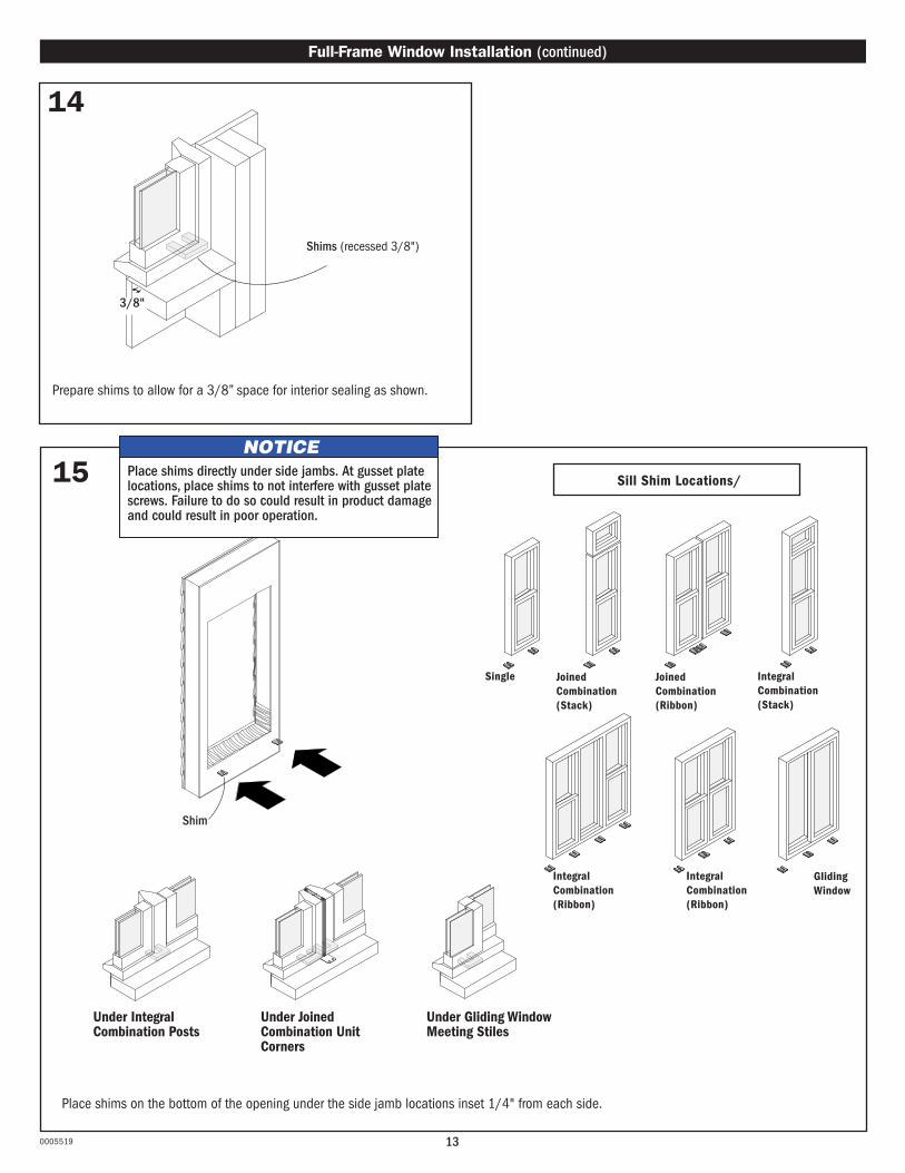
15
Shim
Place shims on the bottom of the opening under the side jamb locations inset 1/4" from each side.
Under Integral Combination Posts
Under Joined Combination Unit Corners
Under Gliding Window Meeting Stiles
Sill Shim Locations/
Single Joined Combination (Stack)
Joined Combination (Ribbon)
Integral Combination (Stack)
Integral Combination (Ribbon)
Gliding Window
Integral Combination (Ribbon)
14
Prepare shims to allow for a 3/8” space for interior sealing as shown.
NOTICEPlace shims directly under side jambs. At gusset plate locations, place shims to not interfere with gusset plate screws. Failure to do so could result in product damage and could result in poor operation.
Shims (recessed 3/8")
3/8"

140005519
Full-Frame Window Installation (continued)
Shim Middle
Shim Sides
Do not shim at head.
(interior view)
(exterior views)
Place shims at sides next to/straddling predrilled holes in window, as shown. Do not shim at head. Check plumb, level, and square. Adjust shims as needed until diagonal measurements are within 1/8".
18
Position window at desired depth and fasten upper corner to hold in place while shimming. Do not fully tighten.
Combination Square
Fastener (see fastener chart)
17
Side Shim Locations
Integral Combination (Ribbon)
Gliding Window
Single Joined Combination (Stack)
Joined Combination (Ribbon)
Integral Combination (Stack)
Integral Combination (Ribbon)
Center the window in the opening, setting the window on the shims.
16 Support window in opening at all times until secured. Failure to do so may result in window falling out causing injury, property, and/or product damage.

150005519
Full-Frame Window Installation (continued)
Fasten through all predrilled holes using installation screws supplied.
19NOTICE
• Installation screws, clips and/or gusset plates must be securely attached to the opening. Failure to do so will reduce the structural performance to less than published values resulting in product/property damage. • Check if frame is bowed. Correct any frame bow during installation. Failure to do so could result in product/property damage.

160005519
Full-Frame Window Installation (continued)
20
Fasten through installation clip(s) and gusset plate(s) if present.
Units with Sill Installation Clips Only
Fastener (see fastener chart)
Fasten through gusset plates
Gusset Plate
Non-Reinforced Join
Gusset Plate
Fastener (see fastener chart)
Reinforced Join(Reinforced joins are not available for flangeless
windows with an exterior accessory kerf)
1
Apply sealant under installation clip, between clip and opening.
IMPORTANTStraighten or bend installation clips into position as appropriate for anchoring window to framing.
2
Straighten installation clips into position against opening and fasten as shown.
3Modify installation clip if necessary.
NOTICE• Installation screws, clips and/or gusset plates must be securely attached to the opening. Failure to do so will reduce the structural performance to less than published values resulting in product/property damage.• If fastening through sill pan, seal at fastener location following sill pan manufacturer’s recommendation. Failure to do so could result in product/property damage.
Joined Combinations Only

Full-Frame Window Installation (continued)
21
170005519
Insert backer rod at sides, top, and bottom.
Lap Siding Manufactured Siding
Brick
Apply sealant to sides, top, and bottom. Smooth out sealant with a putty knife, if required.
Lap Siding Manufactured Siding
Brick
22
NOTICEDo not overpack with backer rod to avoid bowed jambs.
Backer Rod

180005519
▶ Full-Frame Window Installation is complete.
Weep HoleTape
24Do not cover weep holes. Doing so could result in product or property damage.
NOTICE
or/
Reverse angle
Backer Rod
Low Expanding Foam
SealantSpan to fill gap.
Backer Rod
Full-Frame Window Installation (continued)
23
1/3
Remove tape from weep holes (if present) after the exterior trimming/finishing is complete.
NOTICEDo not overfill with low expanding foam or overpack with backer rod to avoid bowed jambs.
2/3
Apply sealant continuously to full perimeter of opening, filling interior 1/3 of cavity as shown using low expanding foam or backer rod and sealant.

190005519
IMPORTANT ▶ Units that require installation clips or joined combinations with gusset plates must
be fastened to the original rough opening and can not be fastened solely to the existing window frame.
▶ Sill stool or extension jamb removal and modification (notching) may be required to allow room for installation clips or gusset plates. Mark locations prior to removal for unit position reference.
▶ Installation clip length may need to be modified so it does not extend past the interior edge of the stool or extension jamb.
1
Check measurements before starting to confirm correct unit size.
2
Break varnish/paint seal along interior stops. Do not damage stops. Stops may be reused.
3
Remove interior stops. Save for reuse if desired.
4
Cut bottom sash balancer cords, if present. Remove bottom sash and dispose of properly. Balancer systems vary.
Existing Window
Insert Window — INTERIOR Installation
Interior Stop
Interior Stop Balancer Cord

200005519
7
Remove pulleys, if present, and dispose of properly.
8
Remove weight pocket covers, if present, and save for reuse.
9
Remove weights, if present, and dispose of properly.
10
Insulate weight pocket and reapply covers. Fill pulley voids with wood for installation screw anchoring area.
Pulley Void
5
Remove parting stops and dispose of properly.
6
Lower top sash to sill. Cut top sash balancer cords, if present. Remove top sash and dispose of properly.
Insert Window — Interior Installation (continued)
Pulley
Weights
Weight Pocket Cover
Insulation
Parting Stop
Balancer Cord
Weight Pocket Cover

210005519
Insect Screen
11
Remove insect screen (if present). Remove head expander (if present).
Insert Window — Interior Installation (continued)
IMPORTANT
Head Expander
Exterior Stop
Visual Gap(between stop
and top of window)
3/4" or Less(space between
opening and top of window)
When dry fitting window, if a visual gap exists between exterior stop and the top of the window, the head expander can be used. The head expander cannot be used if the space between the opening and top of window is greater than 3/4".
▶ Head expander should only be used when there is a gap between the head of the unit and the exterior head stop after shimming at the sill.
▶ If head expander is needed, read and follow the supplemental instructions included with the head expander.
▶ If head expander is not needed, proceed to the next step.

220005519
12
Insert Window — Interior Installation (continued)
Angled Blocking (by others)
NOTICEFull width angled sill support is required for sloped sill openings wider than 48". Failure to do so may result in poor unit performance.
Clean the opening of debris and dry fit window.
- For openings 48" in width and narrower with a sloped sill, level the unit with angled support blocks. Remove window and angled support blocks.
- For sills wider than 48", level sill with full width angled support to convert to a flat sill.
Exterior ViewInterior View
Support window in opening at all times until secured. Failure to do so may result in window falling out causing injury, property, and/or product damage.
WARNING

230005519
Insert Window — Interior Installation (continued)
Measure sill angle height, as shown, and add 1/4" .
Sill angle height: ______ + 1/4" = _______
Cut exterior sill extender trim to height using determined measurements:
Sill angle height + 1/4" (measurement above)
Sill shim height + (determined from dry-fit step)
Exterior sill extender trim height
13 For opening with a sloped sill, apply optional exterior sill extender trim to unit as shown.
Insert exterior sill extender trim into the sill kerf of window by aligning one end with the edge of the unit. Seat along entire width with a wood block and rubber mallet.
3-1/4"
Sill Angle Height
1
2
4
3 Make weep holes by cutting 3/16" x 3/16" notches in bottom trim piece, 3" from each end.
Sill angle height + 1/4" + Sill shim height = Exterior sill extender trim height.
Weep Hole3/16" x 3/16"
3"
Exterior sill extender trim can also be cut to fit between the exterior stops and applied after unit is installed.Refer back to this page if applying the exterior sill extender trim after unit installation.
IMPORTANT

240005519
Predrill installation clearance holes through the frame along the scribe line (if needed) with a 7/32" drill bit as shown. Use the table above to determine the fastener quantity and spacing for each side of the unit. See fastener chart for approved fasteners.
Prep the unit for through the jamb fastening....
Insert Window — Interior Installation (continued)
14
PRODUCT SIDE LENGTH PG40 SPACING PG50 SPACING
Isosceles TriangleRight TrianglePeak Pentagon
0 - 23-1/2" Centered
> 23-1/2" 4-1/2" - 9" from each corner.Max on center spacing of 24"
4-1/2" - 9" from each corner.Max on center spacing of 20"
OctagonUnit width < 47-1/2" one centered screw in every-other jambUnit width > 47-1/2" one centered screw per jamb
ArchUnequal Leg Arch
Half CircleQuarter Circle
Springline
0 - 23-1/2" Centered
> 23-1/2" 4-1/2" - 9" from each corner.Max on center spacing of 20"
Circle 4 fasteners, evenly spaced around the frame
Predrill installation clearance holes along scribe line for fastening to opening.
Specialty Windows Only

250005519
16
Installation Clips at Sill (if provided)(Preferred)
Andersen Installation Sealant (Alternative)
15
Prepare shims to allow for a 3/8" space from the interior face of the unit to the front of the shim to allow for a continuous interior sealant bead as shown.
Shims (recessed 3/8")
Insert Window — Interior Installation (continued)
OR
Failure to properly prepare the opening and use adequate Andersen Installation Sealant may result in product or property damage.
Andersen Installation Sealant may be used at the sill as a structural attachment alternative to installation clips in flat sill insert applications. Locate and apply sealant at the sill as shown in the sealant application steps below.
Apply installation clips following instructions provided with clips.
Apply installation clips (if provided) following instructions provided with clips or prepare sill for Andersen Installation Sealant.
Installation Clips at Sill or Alternative Andersen Installation Sealant at Sill
IMPORTANT
• Clean, dry wood• Well adhered paint• Liquid flashing applied at the sill• Rigid vinyl structurally fastened to the opening
For proper structural adhesion, the opening must be a flat sill with one of the following conditions:
No sealant substitutions may be made.

Clean opening. Apply 3/8" continuous bead of sealant around inside edge of exterior stops at top and sides.
260005519
18
Insert Window — Interior Installation (continued)
19
Flat Sill
17
Verify that the frame is clean, dry, and free of debris. If not, clean the frame using soap and water or non-abrasive solvent free cleaner. Rinse and dry the frame thoroughly after cleaning.
2"
Reverse View Shown
IMPORTANT: Andersen Installation Sealant must be used for alternative structural attachment at the sill.
Apply additional sealant to sill 2" from stool across entire width and liberally in both corners.
Connect the sealant beads at both ends.
Reverse View Shown
3/8" Sealant Beads
Connect the sealant beads at both ends.
3/8" Sealant Beads
Exterior Stops
Sloped Sill
Connect sealant applied to stops to sealant applied at sill.
Apply 3/8" continuous bead of sealant to sill across entire width as shown. Make sure the sealant at the sill connects to the sealant previously applied to the exterior stops.
Andersen Installation Sealant must be used for alternative structural attachment at the sill.

270005519
Integral Combination (Ribbon)
Gliding Window
Single Joined Combination (Stack)
Joined Combination (Ribbon)
Integral Combination (Stack)
Integral Combination (Ribbon)
Insert Window — Interior Installation (continued)
Sloped Sill20
(sealant bead height MUST be greater than shim height.)
Place sill shims in the locations as shown, prior to placing the unit into the opening. Sealant bead height must exceed shim height by a minimum of 1/8". Apply additional sealant as needed and over the shim at any locations where the shim interrupts the sill sealant.
Flat Sill
Under Integral Combination Posts
Under Joined Combination Unit Corners
Under Gliding Window Meeting Stiles
For openings 48" in width and narrower, use angled blocking at the sill. Sill shim locations shown below.
If opening is wider than 48", and full width angled support was applied at the dry fit step, proceed to next step.
Angled Blocking or Full Width Angled Support (by others)
Sill Shim Locations
Shim
Apply additional sealant over the shim(s) at all the locations where the shim interupts the sill sealant bead. Align the additional sealant with the sill sealant bead below the shim.
Sealant Bead

280005519
23
Fasten corners of unit through the predrilled holes using supplied installation screws. Do not fully tighten.
22
Pull sill tight to stool.
21
Lift window into center of opening. Tip top of window against exterior stops. Support window until fastened.
Insert Window — Interior Installation (continued)
Shim directly behind corner screw locations. Adjust shims to center the window and to straighten jambs if necessary. Make sure sash are closed and locked. When diagonal measurements are within 1/8", tighten screws. DO NOT shim at head.
24
Sill
Stool
Shims (recessed 3/8")
Support window in opening at all times until secured. Failure to do so may result in window falling out causing injury, property, and/or product damage.

290005519
Insert Window — Interior Installation (continued)
25
Fasten through installation clip(s) and gusset plate(s) if present.
Units with Sill Installation Clips Only
Fastener (see fastener chart)
Fasten through gusset plates
Gusset Plate
Non-Reinforced Join
Gusset Plate
Fastener (see fastener chart)
Reinforced Join(Reinforced joins are not available for flangeless
windows with an exterior accessory kerf)
1
Apply sealant under installation clip, between clip and opening.
IMPORTANTStraighten or bend installation clips into position as appropriate for anchoring window to framing.
2
Straighten installation clips into position against opening and fasten as shown.
3Modify installation clip if necessary.
Joined Combinations Only
NOTICE• Installation screws, clips and/or gusset plates must be securely attached to the opening. Failure to do so will reduce the structural performance to less than published values resulting in product/property damage.• If fastening through sill pan, seal at fastener location following sill pan manufacturer’s recommendation. Failure to do so could result in product/property damage.

300005519
27
Shim directly behind center screws as shown. Adjust shims to straighten jambs if necessary. Tighten screws when jambs are straight. DO NOT shim at head.
Insert Window — Interior Installation (continued)
26
Fasten through all remaining predrilled holes using supplied installation screws. Do not fully tighten screws.
NOTICECheck if frame is bowed. Correct any frame bow during installation. Failure to do so could result in product/property damage.

310005519
Insert Window — Interior Installation (continued)
29
For sloped sills, apply low expanding foam or sealant to fill void at both ends.
Fill void at both ends with low expanding foam or sealant.
Openings with Sloped Sills Only.
28Backer Rod
3/8" Sealant Bead1/3
2/3
Apply sealant at top and sides, filling interior 1/3 of cavity as shown using low expanding foam. Insert backer rod and apply sealant at top and sides.or
or
Low Expanding Foam
Do not overfill with low expanding foam or overpack with backer rod. Doing so could result in bowed jambs.
NOTICE

30
31 32 33
320005519
Apply sealant at head and side jambs. Remove tape from weep hole (if present.)
Reapply interior stops or measure, cut, and apply new interior head and side stops.
Tape Measure
Head Stop
Side Stop
Head Stop
▶ Insert window Interior Installation is complete.
Insert Window — Interior Installation (continued)
Do not cover weep holes. Doing so could result in product damage.
NOTICE
Weep Hole
Tape
Sealant
Trim Nailer
Apply fillet bead of sealant between the trim pieces and opening as shown. Do not cover weep holes at sill.
Exterior Sill Extender Trim Weep Hole
Sealant

330005519
IMPORTANT ▶ Units that require installation clips or joined combinations with gusset plates must
be fastened to the original rough opening and can not be fastened solely to the existing window frame.
▶ Sill stool or extension jamb removal and modification (notching) may be required to allow room for installation clips or gusset plates. Mark locations prior to removal for unit position reference.
▶ Installation clip length may need to be modified so it does not extend past the interior edge of the stool or extension jamb.
1
Check measurements before starting to confirm correct unit size.
2
Remove exterior stops and dispose of properly.
3
Lower top sash to sill. Cut top sash balancer cords, if present. Remove top sash and dispose of properly.
4
Remove parting stops and dispose of properly.
Insert Window - EXTERIOR Installation
Exterior Stop
Balancer CordParting Stop

340005519
7
Remove weight pocket covers, if present, and save for reuse.
8
Remove weights, if present, and dispose of properly.
9
Insulate weight pocket and reapply covers. Fill pulley voids with wood for installation screw anchoring.
Pulley Void
5
Cut bottom sash balancer cords, if present. Remove bottom sash and dispose of properly. Balancer systems may vary.
6
Remove pulleys, if present, and dispose of properly.
Insert Window — Exterior Installation (continued)
Weight Pocket Cover
Weights
Insulation
Weight Pocket Cover
Pully

350005519
Insert Window — Exterior Installation (continued)
Insect Screen
10
Remove insect screen (if present). Remove head expander (if present).
IMPORTANT
Head Expander
Interior Stop
Visual Gap(between stop
and top of window)
3/4" or Less(space between
opening and top of window)
When dry fitting window, if a visual gap exists between interior stop and the top of the window, the head expander can be used. The head expander cannot be used if the space between the opening and top of window is greater than 3/4".
▶ Head expander should only be used when there is a gap between the head of the unit and the interior head stop after shimming at the sill.
▶ If head expander is needed, read and follow the supplemental instructions included with the head expander.
▶ If head expander is not needed, proceed to the next step.

360005519
11
Angled Blocking (by others)
Angled Blocking or Full Width Angled Support (by others)
Full width angled sill support is required for sloped sill openings wider than 48". Failure to do so may result in poor unit performance.
Clean the opening of debris and dry fit window.
- For openings less than 48" in width with a sloped sill, level the unit with angled support blocks. Remove window and angled support blocks.
- For sills wider than 48", level sill with full width angled support to convert to a flat sill.
Exterior View
Support window in opening at all times until secured. Failure to do so may result in window falling out causing injury, property, and/or product damage.
WARNING
Insert Window — Exterior Installation (continued)
NOTICE

370005519
Insert Window — Exterior Installation (continued)
Predrill installation clearance holes through the frame along the scribe line (if needed) with a 7/32" drill bit as shown. Use the table above to determine the fastener quantity and spacing for each side of the unit. See fastener chart for approved fasteners.
12
PRODUCT SIDE LENGTH PG40 SPACING PG50 SPACING
Isosceles TriangleRight TrianglePeak Pentagon
0 - 23-1/2" Centered
> 23-1/2" 4-1/2" - 9" from each corner.Max on center spacing of 24"
4-1/2" - 9" from each corner.Max on center spacing of 20"
OctagonUnit width < 47-1/2" one centered screw in every-other jambUnit width > 47-1/2" one centered screw per jamb
ArchUnequal Leg Arch
Half CircleQuarter Circle
Springline
0 - 23-1/2" Centered
> 23-1/2" 4-1/2" - 9" from each corner.Max on center spacing of 20"
Circle 4 fasteners, evenly spaced around the frame
Predrill installation clearance holes along scribe line for fastening to opening.
Specialty Windows Only

380005519
13
Prepare shims to allow for a 3/8" space from the exterior face of the unit to the front of the shim to allow space for sealant as shown.
Insert Window — Exterior Installation (continued)
Shims (recessed 3/8")
14
Installation Clips at Sill (if provided)(Preferred)
Andersen Installation Sealant (Alternative)
OR
Failure to properly prepare the opening and use adequate Andersen Installation Sealant may result in product or property damage.
Andersen Installation Sealant may be used at the sill as a structural attachment alternative to installation clips in flat sill insert applications. Locate and apply sealant at the sill as shown in the sealant application steps below.
Apply installation clips following instructions provided with clips.
Apply installation clips (if provided) following instructions provided with clips or prepare sill for Andersen Installation Sealant.
Installation Clips at Sill or Alternative Andersen Installation Sealant at Sill
IMPORTANT
• Clean, dry wood• Well adhered paint• Liquid flashing applied at the sill• Rigid vinyl structurally fastened to the opening
For proper structural adhesion, the opening must be a flat sill with one of the following conditions:
No sealant substitutions may be made.

Clean opening. Apply 3/8" continuous bead of sealant around outside edge of interior stops at top and sides.
390005519
15
17
Flat Sill
16
Insert Window — Exterior Installation (continued)
Verify that the frame is clean, dry, and free of debris. If not, clean the frame using soap and water or non-abrasive solvent free cleaner. Rinse and dry the frame thoroughly after cleaning.
Interior Stops
2"
3/8" Sealant Beads 3/8" Sealant Beads
IMPORTANT: Andersen Installation Sealant must be used for alternative structural attachment at the sill.
Apply additional sealant to sill 2" from stool across entire width and liberally in both corners.
Connect the sealant beads at both ends.
Apply 3/8" continuous bead of sealant to sill across entire width. Make sure the sealant at the sill connects to the sealant previously applied to the interior stops.
Andersen Installation Sealant must be used for alternative structural attachment at the sill.
Connect the sealant beads at both ends.
Sloped Sill

400005519
Insert Window (Exterior Installation) Continued
Integral Combination (Ribbon)
Gliding Window
Single Joined Combination (Stack)
Joined Combination (Ribbon)
Integral Combination (Stack)
Integral Combination (Ribbon)
Sloped Sill18
Place sill shims in the locations as shown, prior to placing the unit into the opening. Sealant bead height must exceed shim height by a minimum of 1/8". Apply additional sealant as needed and over the shim at any locations where the shim interrupts the sill sealant.
Flat Sill
Under Integral Combination Posts
Under Joined Combination Unit Corners
Under Gliding Window Meeting Stiles
Angled Blocking or Full Width Angled Support (by others)
Sill Shim Locations
Shim
Apply additional sealant over the shim(s) at all the locations where the shim interupts the sill sealant bead. Align the additional sealant with the sill sealant bead below the shim.
For openings 48" in width and narrower, use angled blocking at the sill. Sill shim locations shown below.
If opening is wider than 48", and full width angled support was applied at the dry fit step, proceed to next step.
(sealant bead height MUST be greater than shim height.)
Sealant Bead

410005519
Lift window into center of opening and press against stool and interior stops. Support window until fastened.
19
Reverse Angle
20
Fasten corners of unit through the predrilled holes using supplied installation screws. Do not fully tighten.
21
Shim directly behind corner screw locations. Adjust shims to center the window and to straighten jambs if necessary. Make sure sash are closed and locked. When diagonal measurements are within 1/8", tighten screws. DO NOT shim at head.
Insert Window — Exterior Installation (continued)
Support window in opening at all times until secured. Failure to do so may result in window falling out causing injury, property, and/or product damage.
Interior View

420005519
Insert Window — Exterior Installation (continued)
22
Fasten through installation clip(s) and gusset plate(s) if present.
Units with Sill Installation Clips Only
Fastener (see fastener chart)
Fasten through gusset plates
Gusset Plate
Non-Reinforced Join
Gusset Plate
Fastener (see fastener chart)
1
Apply sealant under installation clip, between clip and opening.
IMPORTANTStraighten or bend installation clips into position as appropriate for anchoring window to framing.
2
Straighten installation clips into position against opening and fasten as shown.
3Modify installation clip if necessary.
NOTICE• Installation screws, clips and/or gusset plates must be securely attached to the opening. Failure to do so will reduce the structural performance to less than published values resulting in product/property damage.• If fastening through sill pan, seal at fastener location following sill pan manufacturer’s recommendation. Failure to do so could result in product/property damage.
Joined Combinations Only
Reinforced Join(Reinforced joins are not available for flangeless
windows with an exterior accessory kerf)
430005519
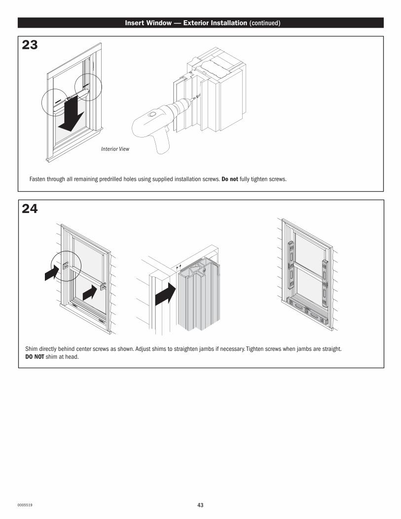
24
Insert Window — Exterior Installation (continued)
23
Interior View
Fasten through all remaining predrilled holes using supplied installation screws. Do not fully tighten screws.
Shim directly behind center screws as shown. Adjust shims to straighten jambs if necessary. Tighten screws when jambs are straight. DO NOT shim at head.

25
Backer Rod
3/8" Sealant Bead
440005519
26
For sloped sill, apply additional low expanding foam or sealant to bottom corners on both ends.
For Sloped Sill Only.
Insert Window — Exterior Installation (continued)
Insert backer rod and apply sealant at top and sides.
NOTICEDo not overfill with low expanding foam or overpack with backer rod to avoid bowed jambs.
NOTICEDo not overfill with low expanding foam or overpack with backer rod to avoid bowed jambs.
Apply sealant at top and sides, filling interior 1/3 of cavity as shown using low expanding foam.
Fill void on both ends with low expanding foam or sealant.
Low Expanding Foam
1/3
2/3
27

450005519
For opening with a sloped sill, apply optional exterior sill extender trim to unit as shown.
Insert Window — Exterior Installation (continued)
Measure sill angle height, as shown.
1
3 Make weep holes by cutting 3/16" x 3/16" notches in bottom trim piece, 3" from each end.
2
Weep Hole3/16" x 3/16"
3"
Add 1/4" to measurement from previous step. Cut trim piece to proper dimension.
Insert sill trim piece into accessory kerf and seat by tapping with a wood block and rubber mallet. Clean sealant squeeze out as needed.
4 Apply color matched sealant to bottom accessory kerf.
5
Do not cover weep holes
28
Measurement + 1/4"
6 Apply fillet bead of sealant between the trim pieces and opening as shown. Do not cover weep holes at sill.
Sill Angle Height
Exterior Sill Extender Trim

460005519
▶ Insert Window Exterior Installation is complete.
Weep HoleTape
29Do not cover weep holes. Doing so could result in product damage.
NOTICE
Remove tape from weep holes (if present) after the exterior trimming/finishing is complete.