fundamental design examples of digital ship earth … · the signalling system and numbering plan...
TRANSCRIPT
Rep. ITU-R M.921-3 1
REPORT ITU-R M.921-3
Fundamental design examples of digital ship earth stations
(1982-1986-1990-2004)
1 Introduction This Report addresses a number of technical aspects to system and communications channel characteristics for digital ship earth station standards, in particular the trade-offs between system requirements for efficient space segment capacity utilization and the user requirements for small, compact shipborne equipment.
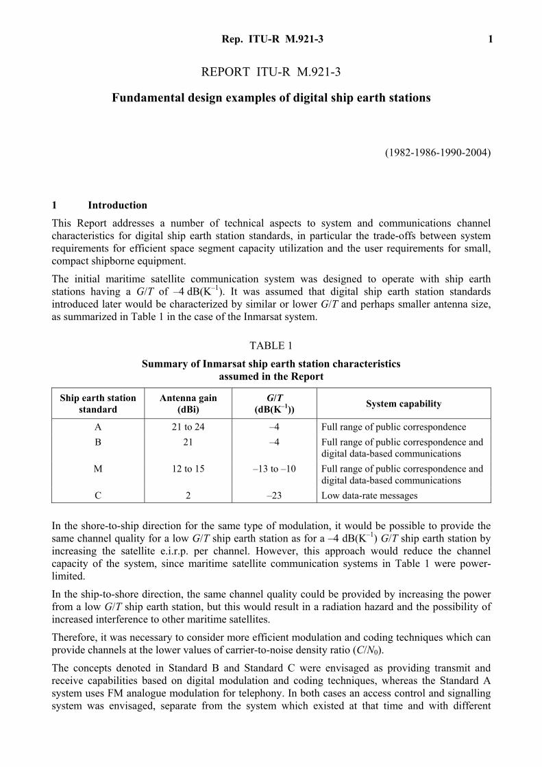
The initial maritime satellite communication system was designed to operate with ship earth stations having a G/T of –4 dB(K–1). It was assumed that digital ship earth station standards introduced later would be characterized by similar or lower G/T and perhaps smaller antenna size, as summarized in Table 1 in the case of the Inmarsat system.
TABLE 1
Summary of Inmarsat ship earth station characteristics assumed in the Report
Ship earth station standard
Antenna gain (dBi)
G/T (dB(K–1)) System capability
A 21 to 24 –4 Full range of public correspondence B 21 –4 Full range of public correspondence and
digital data-based communications M 12 to 15 –13 to –10 Full range of public correspondence and
digital data-based communications C 2 –23 Low data-rate messages
In the shore-to-ship direction for the same type of modulation, it would be possible to provide the same channel quality for a low G/T ship earth station as for a –4 dB(K–1) G/T ship earth station by increasing the satellite e.i.r.p. per channel. However, this approach would reduce the channel capacity of the system, since maritime satellite communication systems in Table 1 were power-limited.
In the ship-to-shore direction, the same channel quality could be provided by increasing the power from a low G/T ship earth station, but this would result in a radiation hazard and the possibility of increased interference to other maritime satellites.
Therefore, it was necessary to consider more efficient modulation and coding techniques which can provide channels at the lower values of carrier-to-noise density ratio (C/N0).
The concepts denoted in Standard B and Standard C were envisaged as providing transmit and receive capabilities based on digital modulation and coding techniques, whereas the Standard A system uses FM analogue modulation for telephony. In both cases an access control and signalling system was envisaged, separate from the system which existed at that time and with different

2 Rep. ITU-R M.921-3
channel characteristics which were expected to provide enhanced signalling efficiency and capacity. In the Standard B system, demand assignment of channels was based on forward TDM links which might be used for centralized or distributed access control within each network. Such links, coupled with ship earth station request (random access) and response (TDMA) signalling channels, also enable adaptive power control and satellite spot-beam identification procedures to be implemented. In the Standard C system, communications and signalling information were combined in forward TDM and return random access links, using ARQ techniques.
Annex 1 describes a digital ship earth station development similar to the envisaged Standard B system with G/T values of –10 dB(K–1) and–4 dB(K–1). Annex 2 describes the performance of a low G/T ship earth station (G/T = –13 dB(K–1)) with a 2 400 bit/s vocoder channel. Annex 3 discusses the concept of enhanced group call system. Annex 4 presents experimental results on the forward error correction (FEC) as a means of multipath fading compensation. Annex 5 describes in more detail the proposed Inmarsat Standard C system.
2 Design basis of digital system
2.1 System concept and application aspects The eventual introduction of a Standard B system was assumed to represent a means of providing a successor to Inmarsat Standard A ship earth stations for the full range of public correspondence service, including the following: – telephony, based on digital modulation, coding and speech processing techniques, including
voiceband data; – data for low-speed service (up to around 9.6 kbit/s), including telegraphy, teletex and
facsimile.
The signalling system and numbering plan adopted for ship earth station would allow interconnection at coast earth stations between the satellite channels and the appropriate terrestrial networks for telephony, telex and data, including the capability for interworking with the integrated services digital network (ISDN).
In addition to the above basic services, it was also assumed that a Standard B system would continue to provide the other capabilities available with Standard A such as telephone and telex distress alerting, ship-to-shore high-speed data at 56 kbit/s, multichannel operation, plus a range of data services at 16 kbit/s and above.
It was expected that the main services requirement in terms of space segment utilization would continue to be telephony. The introduction of digital techniques would provide the opportunity for saving in satellite power and bandwidth, or a reduction in ship earth station G/T and e.i.r.p. requirements, or a combination of both.
In order to maintain the telephone channel subjective quality currently provided by Standard A (see Recommendation ITU-R M.547), it was assumed that a design objective for Standard B would be to provide good quality telephony under nominal conditions at low satellite elevation angles. Furthermore it was assumed that the satellite e.i.r.p. required to meet these objectives would be comparable to that required for Standard A. By applying voice activation and power control on forward links, the average satellite e.i.r.p. per channel would be further reduced to less than that required for Standard A.
A digital implementation of ship earth station equipment would support a wide variety of data transmission.
Rep. ITU-R M.921-3 3
2.2 Voice coding techniques Digital modulation and voice coding techniques could provide the required voice quality more efficiently than analogue modulation. The application of efficient digital voice coding methods would serve to reduce bandwidth requirements which, coupled with FEC would also reduce the value of C/N0 which determines the satellite power requirement in the shore-to-ship direction, the most power-limited link in the system. Such techniques would also serve to minimize ship earth station e.i.r.p. requirements in the ship-to-shore direction. It was expected that the continuing development of LSI circuit technology would enable the necessary digital technique to be realized in a cost-effective manner.
One conclusion to be drawn from the comparison of available voice coding techniques was that the required speech quality objectives could be achievable with 16 kbit/s voice coding rate and a bit error ratio (BER) of around 10–2 to 10–3, using adaptive-predictive coding (APC) or sub-band coding (SBC) as the voice coding method. This would also provide the opportunity to achieve a reduction in channel spacing to 20-25 kHz, depending on the modulation and FEC coding technique adopted.
Available information at that time suggested that the subjective speech quality obtainable with lower rate vocoder techniques was not yet sufficient for the desired quality objectives, and that further study and development was required in this area. However, these systems demonstrated a useful potential for reductions in satellite power and bandwidth requirements at coding rates around 9.6 kbit/s or less, and could thus be applied to maritime and perhaps other mobile satellite communication services. As an example, 9.6 kbit/s APC could be applied to the –10 dB(K–1) variant of the Standard B System and was expected to provide acceptable voice quality for public correspondence.
2.3 Modulation techniques Various digital modulation techniques which were potentially applicable to Standard B would be considered, and the resultant BER performance characteristics, bandwidth utilization efficiency and hardware complexity would be compared.
For shore-to-ship transmissions, filtered 4-PSK would be an efficient modulation technique but because of its varying amplitude characteristics, a liner (Class A) amplifier at the ship earth station would be required for ship-to-shore transmissions. However, offset 4-PSK modulation with smaller amplitude variation would be compatible with existing (Class C) amplifiers, and could be used with only minor degradations in spectral efficiency and BER performance.
2.4 FEC techniques The application of FEC to digital channels for voice transmission to and from ship earth stations would enable the value of C/N0 required to meet the BER criterion derived from the speech quality objective to be reduced significantly, irrespective of the type of voice coding techniques adopted.
Figure 1 shows the C/N0 requirement for 2-PSK or 4-PSK channels at various bit rates, without FEC and with FEC. For practical application, an additional 1 to 2 dB should be included for implementation margins, although later developments suggested that implementation margins less than 1 dB might be appropriate. It is obvious from the figure that FEC techniques are very effective in reducing the value of C/N0 for a given bit rate.
Rate 1/2 convolutional coding (constraint length k = 7) with soft decision Viterbi decoding had been widely used in satellite systems and was thus a well-proven technique; implementation in VLSI was available. Coding gains achievable in practice were close to theoretical predictions: around 3.8 dB at 10–3 output BER and 5.2 dB at 10–5 BER.

4 Rep. ITU-R M.921-3
FIGURE 1 C/N0 as a function of bit rate
Rate 3/4 coding with Viterbi decoding was not at that time as widely applied as rate 1/2 FEC, and required more complex processing. Practical coding gains were of the order of 2.8 kB at 10–3 output BER and 4.3 dB at 10–5 BER (i.e. about 1 dB less than rate 1/2), but the bandwidth expansion factor was reduced significantly (i.e. 1.8 dB less than rate 1/2).
The complexity of rate 3/4 coding could be significantly reduced by applying “punctured” coding techniques to the basic rate 1/2 code. This required deletion of two bits in every six coded bits in the rate 1/2 coded data stream, transmission of the remaining four bits at rate 3/4, and insertion of two additional bits at the receiver prior to rate 1/2 Viterbi decoding. Another potential application was the implementation of codecs with flexible coding rates switchable between rate 1/2 and rate 3/4. BER performance with punctured coding was only marginally inferior to non-punctured techniques, requiring 0.2 dB additional Eb/N0 at 10–5 BER and essentially no degradation at 10–3 BER.
It was concluded that 3/4 FEC offers significant advantages for a Standard B system, providing efficient spectral efficiency and good power utilization. Rate 1/2 FEC could be appropriate to a more power-limited system, where 1 dB savings in satellite and ship earth station e.i.r.p. requirements could be achieved at the expense of less efficient bandwidth utilization.
Rep. ITU-R M.921-3 5
Further it was noted that after Viterbi decoding all errors, including random errors, appear as burst errors. Also since the transmission quality of digital channels was affected differently by burst and random errors it cannot be directly determined by BER.
In addition in mobile satellite communications both random errors and burst errors due to multipath fading occur. It was, therefore, necessary to evaluate the statistical characteristics of burst errors after Viterbi decoding including the effect of multipath fading.
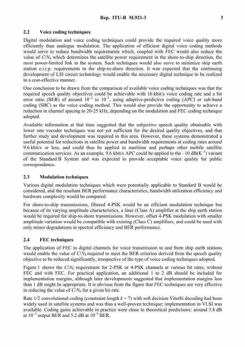
The output error characteristics after Viterbi decoding had been studied experimentally and statistically [Yasuda et al., 1988]. As a result, it was clarified that the error burst under multipath fading conditions was longer than region sandwiched between two error-free continuations of more than 20 bits. Figure 2 shows the results of the measurements by simulation models and Table 2 gives conditions not included in the Figure.
FIGURE 2 Measured cumulative distribution of error burst length
TABLE 2
Major parameters of the measured system
Information bit rate 16 kbit/s
Viterbi decoding – Constraint length: 7 – Coding rate: 1/2
2.5 Standard B design example The following design example describes the Standard B system concept being studied at that time by Inmarsat.

6 Rep. ITU-R M.921-3
The basic telephony channel uses 16 kbit/s APC voice coding with offset-QPSK modulation and rate 3/4 FEC, to give an effective channel rate of 24 kbit/s over the SCPC satellite link in both directive channel rate of 24 kbit/s shore-to-ship carriers and power control depending on ship earth station elevation of 15-16 dBW per carrier with –4 dB(K–1) ship earth station G/T. The corresponding ship earth station maximum e.i.r.p. required is 34 dBW for operation to Inmarsat first-generation satellites. Minimum channel separation is 20 kHz to provide for acceptable channel BER performance in the presence of adjacent channel interference.
The same basic channel design is also used to provide data at 9.6 kbit/s (with rate 1/2 FEC giving 10 BER) and at 16 kbit/s (rate 3/4 FEC, 10–3 BER which can be improved by the use of ARQ by the end users). Sub-band signalling fields within the channel frame, constituting a 96 bit signal unit per 80 ms frame, are used for transmission addressing (ship-to-shore), supervisory functions after call set-up and to provide additional signalling capacity for future ISDN connections.
Call set-up is performed by means of out-of-band signalling channels, transmitted as appropriate by the network coordination station (NCS), coast earth station (CES) and ship earth station (SES).
3 Low G/T, data only, system concept (Standard C) The ship earth station characteristics inherent in Standard A and the envisaged Standard B concept may not be optimum for smaller vessels which constitute a large proportion of the maritime community, in particular where voice-grade communications are not required and where space for equipment installation is limited.
The Standard C concept could enable satellite communications facilities to be extended to such vessels, by means of a relatively simple, compact ship earth station providing message-based capabilities at a channel rate of 600 bit/s. The ship earth station would be characterized by an unstabilized and unsteered antenna system. Potential applications for the system include both-way distress alerting, reception of safety messages, transmission of meteorological data, public correspondence and ship polling, with the following message transmission: – text in the appropriate alphabet by the user; – graphics and facsimile; – information and control instructions for user peripherals such as voice-synthesis equipment.
In view of the projected low G/T of the Standard C ship earth station, efficient modulation and coding techniques need to be adopted in order to minimize satellite and ship earth station e.i.r.p. requirements. The choice of technique should also be compatible with anticipated antenna characteristics, channel bit rates and system efficiency.
For typical ship motion characteristics applied A designs, the maximum antenna gain for an unstabilized Standard C antenna would be of the order of 2 dBi. In the shore-to-ship direction a satellite e.i.r.p. of 20 dBW could then support a channel bit rate of 600 bit/s; an increase in e.i.r.p. would enable higher bit rates to be achieved. In the ship-to-shore direction, practical limitations on ship earth station transmit amplifiers cause the channel rate to be restricted to around 600 bit/s.
At these bit rates an efficient modulation technique would be 2-PSK, with rate 1/2 convolutional coding as the basic FEC technique to improve the system margin. For the ship-to-shore direction, sensitivity to potential interference could be minimized by the use of block coding, linked with an inner convolutional code. In both cases the fading margin due to multipath effects would be significantly reduced by means of interleaving, which would disperse error bursts into a random pattern correctable by FEC, as opposed to improving the antenna discrimination. This would incur transmission delays of up to 20 s, and would thus result in an inability to provide real-time communications such as telephony in the future, although such a capability for small ship earth stations is envisaged for a Standard B variant, e.g. as described in Annexes 1 and 2.
Rep. ITU-R M.921-3 7
Measurements of FEC performance with antenna systems of the Standard C type are reported in Annex 4 as a means of compensating for multipath fading effects. These measurements show that it will be necessary to use FEC with interleaving in order to improve channel error performance on faded links of a Standard C system with continuous transmissions.
A description of the Inmarsat Standard C system based on the above concepts is given in Annex 5.
4 Link budget considerations
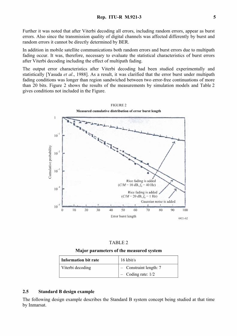
4.1 Multipath fading characteristics The Standard B and, in particular, Standard C ship earth station concepts indicated a general trend at that time towards smaller antenna system which, in view of their reduced directivity, would be more susceptible than Standard A to multipath fading effects.
Figure 3 shows a simple multipath fading model derived from theoretical considerations and from measurement data (see Annexes 1 and 2 to this Report). The model is based on antenna directivity for gains in the range 7-25 dBi, and shows fade margins (99% of the time under Rice-Nakagami fading conditions) for “moderate” sea states at 5° and 10° elevation. Also shown is the potential advantage provided by the application of multipath fading reduction (polarization shaping technique) to the antenna system.
FIGURE 3 Multipath fading characteristics (99% time Rice-Nakagami fading)

8 Rep. ITU-R M.921-3
4.2 Pointing/tracking error characteristics Pointing/tracking errors for a passively-stabilized ship earth station antenna, due to ship motion, had been studied in Japan. This information could be used to determine link budget losses for representative antenna systems.
4.3 Link budget examples Example link power budgets for a voice channel BER objective of 10–3 are shown for a Standard B ship earth station (Case 1: G/T = –4 dB(K–1)) and the Standard M system (Case 2: G/T = –10 dB(K–1)) operating through an Inmarsat second-generation satellite. In the latter case, the potential link quality (C/N0) improvements due to multipath fading reduction (polarization shaping) are also indicated.
TABLE 3
Example link budgets for digital voice-grade ship earth stations Coast earth station elevation angle: 5° Ship earth station elevation angle: 10°
Shore-to-ship link
Ship earth station standards Case 1 Case 2
Shore-to-satellite (6.42 GHz): – CES nominal e.i.r.p. (dBW) 52.0 60.0 – free-space path loss (dB) 200.9 200.9 – atmospheric absorption (dB) 0.4 0.4 – satellite G/T (dB(K–1)) –14.0 –14.0 – up-path C/N0 (dBHz) 65.3 73.3 – satellite C/IM0 (dBHz) 60.5 68.5 Satellite-to-ship (1.54 GHz): – satellite nominal e.i.r.p. (dBW) 13.0 21.0 – free-space path loss (dB) 188.9 188.4 – atmospheric absorption (dB) 0.2 0.2 – SES G/T (dB(K–1)) –4.0 –10.0 – down-path C/N0 (dBHz) 49.0 51.0 Overall unfaded C/N0 (dBHz) 48.6 50.9 Fading loss (dB) 2.0 4.4 (2.7) Overall faded C/N0 (dBHz) 46.6 46.5 (48.2)
Rep. ITU-R M.921-3 9
TABLE 3 (end)
Ship-to-shore link
Ship earth station standards Case 1 Case 2
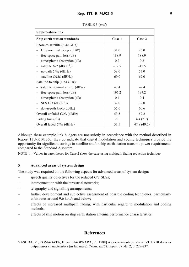
Shore-to-satellite (6.42 GHz): – CES nominal e.i.r.p. (dBW) 31.0 26.0 – free-space path loss (dB) 188.9 188.9 – atmospheric absorption (dB) 0.2 0.2 – satellite G/T (dB(K–1)) –12.5 –12.5 – up-path C/N0 (dBHz) 58.0 53.0 – satellite C/IM0 (dBHz) 69.0 69.0 Satellite-to-ship (1.54 GHz): – satellite nominal e.i.r.p. (dBW) –7.4 –2.4 – free-space path loss (dB) 197.2 197.2 – atmospheric absorption (dB) 0.4 0.4 – SES G/T (dB(K–1)) 32.0 32.0 – down-path C/N0 (dBHz) 55.6 60.6 Overall unfaded C/N0 (dBHz) 53.5 52.2 Fading loss (dB) 2.0 4.4 (2.7) Overall faded C/N0 (dBHz) 51.5 47.8 (49.5)
Although these example link budgets are not strictly in accordance with the method described in Report ITU-R M.760, they do indicate that digital modulation and coding techniques provide the opportunity for significant savings in satellite and/or ship earth station transmit power requirements compared to the Standard A system. NOTE 1 – Values in parentheses for Case 2 show the case using multipath fading reduction technique.
5 Advanced areas of system design The study was required on the following aspects for advanced areas of system design: – speech quality objectives for the reduced G/T SESs; – interconnection with the terrestrial networks; – telegraphy and signalling arrangements; – further development and subjective assessment of possible coding techniques, particularly
at bit rates around 9.6 kbit/s and below; – effects of increased multipath fading, with particular regard to modulation and coding
methods; – effects of ship motion on ship earth station antenna performance characteristics.
References
YASUDA, Y., KOMAGATA, H. and HAGIWARA, E. [1988] An experimental study on VITERBI decoder output error characteristics (in Japanese). Trans. IEICE Japan, J71-B, 2, p. 229-237.

10 Rep. ITU-R M.921-3
Annex 1
Performance characteristics of a digital voice-grade ship earth station
This Annex presents an example of concept of such a ship earth station employing efficient digital communication technologies [Hirata et al., 1984], and its performance characteristics based on the results of a field experiment using two types of antenna system (medium gain and high gain).
1 System design The digital ship earth station system described here was designed to be used in the Inmarsat system and to operate in the SCPC mode at carrier spacings of 20 kHz.
Table 4 shows the basic parameters of the telephone signal transmission channel of the digital ship earth station system. The system employs 16 kbit/s (switchable to 9.6 kbp/s) voice coding using adaptive predictive coding with maximum likelihood quantization (APC-MLQ) [Yatsuzuka et al., 1986], rate 3/4 (switchable to rate 1/2) punctured convolutional coding/soft decision Viterbi decoding [Yasuda et al., 1984] and offset-QPSK (OQPSK, switchable to QPSK). The transmission bit rate is 24 kbit/s which results from the 22.4 kbit/s additive data for frame synchronization.
TABLE 4
Major parameters of the digital communication channel
Information bit rate 16 kbit/s and 9.6 kbit/s Voice coding APC-MLQ (adaptive predictive coding
with maximum likelihood quantization) FEC Rate 3/4 and 1/2 punctured coding (k = 7)/
8-level soft decision Viterbi decoding Modulation Offset QPSK and QPSK Tx/Rx filters Square root raised-cosine Nyquist filter
with 60% roll-off for OQPSK 40% roll-off for QPSK
Transmission bit rate 24 kbit/s Carrier spacing 20 kHz (minimum) Operation mode Voice activation operation in shore-to-ship
direction
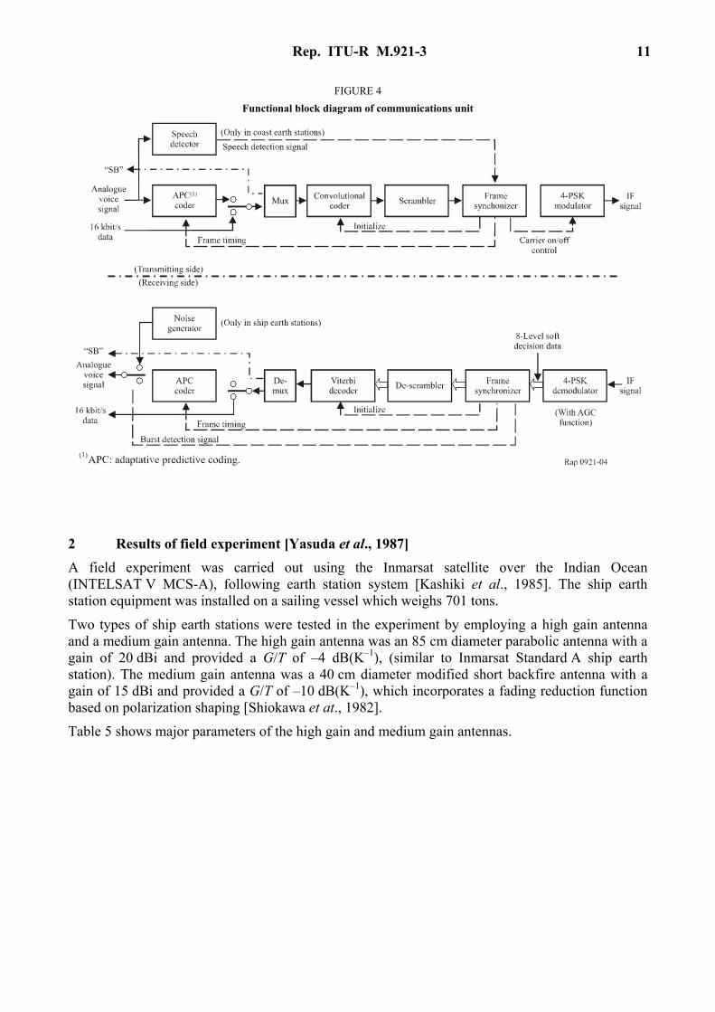
Figure 4 shows the functional block digital communications unit for the system. In addition to the APC-MLQ codec, the FEC codec and the modem, a speech detector which performs voice activation in the shore-to-ship direction is used in the coast earth station, and a noise generator is provided in the ship earth station to provide a more natural listening environment. Voice activation will allow efficient use of satellite power in the satellite-ship direction.
Rep. ITU-R M.921-3 11
FIGURE 4 Functional block diagram of communications unit
2 Results of field experiment [Yasuda et al., 1987] A field experiment was carried out using the Inmarsat satellite over the Indian Ocean (INTELSAT V MCS-A), following earth station system [Kashiki et al., 1985]. The ship earth station equipment was installed on a sailing vessel which weighs 701 tons.
Two types of ship earth stations were tested in the experiment by employing a high gain antenna and a medium gain antenna. The high gain antenna was an 85 cm diameter parabolic antenna with a gain of 20 dBi and provided a G/T of –4 dB(K–1), (similar to Inmarsat Standard A ship earth station). The medium gain antenna was a 40 cm diameter modified short backfire antenna with a gain of 15 dBi and provided a G/T of –10 dB(K–1), which incorporates a fading reduction function based on polarization shaping [Shiokawa et at., 1982].
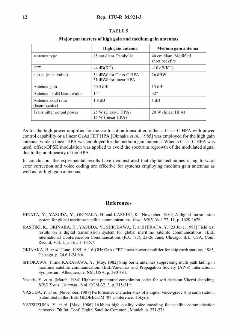
Table 5 shows major parameters of the high gain and medium gain antennas.
12 Rep. ITU-R M.921-3
TABLE 5
Major parameters of high gain and medium gain antennas
High gain antenna Medium gain antenna
Antenna type 85 cm diam. Parabolic 40 cm diam. Modified short backfire
G/T –4 dB(K–1) –10 dB(K–1) e.i.r.p. (max. value) 34 dBW for Class-C HPA
31 dBW for linear HPA 26 dBW
Antenna gain 20.5 dBi 15 dBi Antenna –3 dB beam width 14° 32° Antenna axial ratio (beam-centre)
1.8 dB 1 dB
Transmitter output power 25 W (Class-C HPA) 15 W (linear HPA)
20 W (linear HPA)
As for the high power amplifier for the earth station transmitter, either a Class-C HPA with power control capability or a linear GaAs FET HPA [Okinaka et al., 1985] was employed for the high gain antenna, while a linear HPA was employed for the medium gain antenna. When a Class-C HPA was used, offset-QPSK modulation was applied to avoid the spectrum regrowth of the modulated signal due to the nonlinearity of the HPA.
In conclusion, the experimental results have demonstrated that digital techniques using forward error correction and voice coding are effective for systems employing medium gain antennas as well as for high gain antennas.
References
HIRATA, Y., YASUDA, Y., OKINAKA, H. and KASHIKI, K. [November, 1984] A digital transmission system for global maritime satellite communications. Proc. IEEE, Vol. 72, 11, p. 1620-1626.
KASHIKI, K., OKINAKA, H., YASUDA, Y., SHIOKAWA, T. and HIRATA, Y. [23 June, 1985] Field test results on a digital transmission system for global maritime satellite communications. IEEE International Conference on Communications (ICC ’85), 23-26 June, Chicago, ILL, USA, Conf. Record, Vol. 1, p. 16.5.1-16.5.7.
OKINAKA, H. et al. [June, 1985] A 1.6-GHz GaAs FET linear power amplifier for ship earth stations. 1985, Chicago, p. 24.6.1-24.6.6.
SHIOKAWA, T. and KARASAWA, Y. [May, 1982] Ship borne antennas suppressing multi path fading in maritime satellite communication. IEEE/Antennas and Propagation Society (AP-S) International Symposium, Albuquerque, NM, USA, p. 390-393.
Yasuda, Y. et al. [March, 1984] High-rate punctured convolution codes for soft decision Viterbi decoding. IEEE Trans. Common., Vol. COM-32, 3, p. 315-319.
YASUDA, Y. et al. [November, 1987] Performance characteristics of a digital voice-grade ship earth station. (submitted to the IEEE GLOBECOM ’87 Conference, Tokyo).
YATSUZUKA, Y. et al. [May, 1986] 16 kbit/s high quality voice encoding for satellite communication networks. 7th Int. Conf. Digital Satellite Common., Munich, p. 271-278.

Rep. ITU-R M.921-3 13
Annex 2
Performance of an experimental low G/T ship earth station
1 Introduction This Annex presents background of tests carried out with an experimental low G/T SES (–13 dB(K–1)) of the Standard M type which uses a wide beam width antenna and digital modulation techniques.
This work was performed jointly by the United Kingdom Home Office (now the Department of Trade and Industry), British Telecom International (BTI) and the German Aerospace Research Establishment (DFVLR).
These tests were aimed at demonstrating the practicability of this type of SES, and at evaluating its performance at a bit rate of 2 400 bit/s over the present generation of maritime satellite both in conditions prevailing at high elevation angles, essentially unfaded, and in the multipath fading conditions prevailing at low elevation angles.
Some results from the tests are given in [Hagenauer et al., 1984].
References
HAGENAUER, J., DOLAINSKY, ETBAUER, GRABEL, LOTS, PAPKE, W., PLOCHINGER and SCHWEIKERT, R. [November, 1984] Multipath fading effects and data transmission for small ship earth stations (Standard C). DFVLR Final Report, 223 pages (in German). DFVLR, D-8031 Oberpfaffenhofen, Federal Republic of Germany. Prepared under ESA/ESTEC Contract No. 5323/82/NL/JS.
Annex 3
Enhanced group call system
1 Introduction The enhanced group call (EGC) system is a global data broadcast system for commercial group calling, global paging (FleetNETTM) and the dissemination of maritime safety information (SafetyNETTM). The system is part of Inmarsat’s Standard C System and makes use of Standard C common channel TDMs for the transmission of shore-to-ship messages.
The International Convention for the Safety of Life at Sea, 1974, as amended in 1988, requires that every ship be provided with a radio facility for reception of maritime safety information by the Inmarsat enhanced group calling system if the ship is engaged on voyages in any areas of Inmarsat coverage but in which an international NAVTEX application is not provided. The SafetyNET application provides the maritime safety information, including shore-to-ship distress alerts,

14 Rep. ITU-R M.921-3
NAVAREA navigation and meteorological warnings as well as routine weather forecasts may be selectively received by vessels technique. EGC receivers carried on ships to which the 1974 SOLAS Convention applies, are required to meet the IMO performance standards for EGC equipment (IMO Assembly Resolution A. 664)16)).
The FleetNETTM system allows shore-based commercial users to selectively call groups or individual vessels with pre-assigned IDs.
2 System description EGC messages are transmitted on Standard C common channel (NCS) TDMs along with Standard C signalling traffic. This allows EGC terminals to be based on a compact, low cost, low G/T receiver since use is made of the very robust modulation and coding techniques employed for the Standard C System. The receivers may be self contained, stand alone units, or integrated with Standard C or Standard A SESs. Integration with a Standard C SES doses not necessarily require a second receiver, since the Standard C receiver is monitoring the common channel TDM when it is not engaged in traffic. EGC messages are forwarded from the terrestrial network to the Standard C NCS via a Standard C CES.
The operational bandwidth of the EGC system extends from 1 530 to 1 545 MHz with a 5 kHz channel spacing. Adjacent ocean regions will have different frequencies for the EGC carriers. The frequencies of these carries are stored by the receivers so that they may automatically retune once a vessel leaves one ocean region and enters another. Receivers are capable of storing many channel frequencies to allow for expansion and compatibility with future spot beam satellite payloads.
3 Link budget The 1.5/1.6 GHz band link budget for the EGC system is shown in Table 6.
TABLE 6
Link budget for the EGC system
Units MARECS/ INTELSAT V
Inmarsat2
Satellite e.i.r.p. (5°) dBW 21.4 21.0 Free space path loss dB 188.5 188.5 Absorption loss dB 0.4 0.4 Receiver G/T(1) dB/K –23.0 –23.0 Mean downlink C/N0 dBHz 38.1 37.7 Mean unfaded C/N0 dBHz 38.0 37.6 Interference loss dB 0.5 0.5 Random loss (99%) dB 2.2 1.6 Overall C/N0 dBHz 35.4 35.5 Required C/N0 dBHz 34.5 34.5 Margin(2) dB 0.9 1.0
(1) Minimum G/T based on a stand alone EGC or Standard C receiver at 5° satellite elevation.
(2) Link margin greater than 0.9/1.0 dB for 99% of time.

Rep. ITU-R M.921-3 15
The link budgets shown are for the MARECS and INTELSAT-V MCS satellites and the second-generation Inmarsat satellites. The common channel carrier TDM power is approximately 3 dB higher than a Standard A voice carrier. The TDM is BPSK modulated at 1 200 symbols/s (600 bit/s data rate before encoding). FEC Coding is rate 1/2, constraint length 7 convolution with full frame interleaving and a frame length of 10 368 symbols (8.64s). A pair of 64 bit unique words are included in each frame to aid synchronization and ambiguity resolution.
4 Addressing techniques There are three basic methods of addressing EGC receivers, these are: – unique ID addressing (FleetNETTM); – group ID addressing (FleetNETTM); and – area addressing (SafetyNETTM).
EGC receivers that are capable of receiving commercial FleetNETTM messages have a unique 24 bit identity and a number of 24 bit group identities. The group identities are downloadable and erasable over the satellite link. Addressing within the SaftyNET TM application is performed exclusively on the basis of geographical area. Two types of geographical area addressing are possible: a) predefined geographical areas, such as NAVAREAs, WMO areas, NAVTEX coverage
areas and SAR areas; b) absolute areas are defined in terms of a coordinate and a latitudinal and longitudinal
extension (rectangular area addressing), or a coordinate and a radius in nautical miles (circular area addressing).
Receivers may be automatically updated an external navigational instrument and operators may select other areas of interest such as those lying on the vessels expected course.
5 Summary The EGC system provides an effective means for disseminating maritime safety information and for the transmission of shore-to-ship commercial group calls and paging messages. Vessels equipped to receive EGC messages only need a simple low cost receiver, or alternatively, a suitably equipped Inmarsat Standard A or Standard C SES may be used.
Annex 4
Forward error control (FEC) as a means of multipath fading compensation
The performance of coded DECPSK transmission over the Standard C maritime channel was measured by means of the DFVLR channel-simulator test set-up with a modem of new design using a COSTAS-loop combined with an AFC loop (automatic frequency control), in order to recover carrier and data of the DECPSK signal channels (Rayleigh-channel, Rice-Nakagami-channel with C/M = 6.3 dB) as well as for a representative selection channels includes the worst case of 4° elevation angle for all tested antennas C3, C5, C11, C14 and the 19° elevation test for antennas C3 and C11 (Standard C antennas with gains (dB) as indicated). The details are provided in Report ITU-R M.762 and [Hagenauer et al., 1984].
16 Rep. ITU-R M.921-3
References
HAGENAUER, J., DOLAINSKY, ETBAUER, GRABEL, LOTS, PAPKE, W., PLOCHINGER and SCHWEIKERT, R. [November, 1984] Multipath fading effects and data transmission for small ship earth stations (Standard C). DFVLR Final Report, 223 pages (in German). DFVLR, D-8031 Oberpfaffenhofen, Federal Republic of Germany. Prepared under ESA/ESTEC Contract No. 5323/82/NL/JS.
Annex 5
Inmarsat Standard C communications system
1 Introduction The Standard C communications system was designed to permit the fitting of two-way satellite communications system on board the smallest vessels. It was also accepted for fitting as an alternative to Standard A SESs for satisfying the requirements of the 1988 amendments to the 1974 SOLAS Convention for the GMDSS within the Inmarsat satellite coverage area. Standard C terminals fitted on ship to which the 1974 SOLAS Convention applies are required to meet the IMO performance standards for Inmarsat Standard C SESs capable of transmitting and receiving direct-printing communications (IMO Assembly resolution A663(16)).
The system offers a two-way message-based communications application that has been designed to interface with the International Telex Network and a wide range of terrestrial data networks. In addition, an oceanwide broadcast only application known as Enhanced Group Call, is carried by the Standard C communication channels.
1.1 Briefly the Standard C system is described as follows: a) the G/T is –23 dB (K–1) utilizing a small omnidirectional antenna which permits design of
very small equipment; b) digital packet transmission techniques are used with TDM shore-to-ship and TDMA ship-
to-shore for both signalling and message data; c) good error correction performance at low carrier to noise densities is expected by use
1/2 rate convolution coding and interleaving; d) an inter-station (CES and NCS) link permits data exchange for system control purposes; e) operation in a spot beam environment is facilitated by automatic identification of the
satellite spot beam when first turned on.
1.2 These techniques permit the following applications to be carried: a) International telex b) Text broadcasts c) Interactive data exchange and database interrogation d) Priority connection for distress purposes.

Rep. ITU-R M.921-3 17
2 Design implications The adoption of –23 dB (K–1) G/T restricts the system offered to very low data rates and has the following major design implications: a) the forward and return data rates are restricted to 600 bit/s which, with 1/2 rate
convolutional coding and interleaving, permits a high packet success rate to be achieved; b) for the shore-to-ship direction, a relatively high satellite e.i.r.p. of 21 dBW is needed.
3 Link budgets A Standard C link analysis differs from a typical satellite link analysis, because of the ARQ nature of the Standard C system. In a typical system, there is a defined threshold level of C/N0 which defines a quality of service and is a deemed a limit of acceptability; the percentage of time in excess of this threshold is the availability. In Standard C, C/N only affects the number of retransmissions, and hence message delay and the system capacity.
The link budgets presented in Table 7 and Table 8 are termed “worst case”, and this is defined as: – SES and CES at 5o elevation; – minimum values for G/T and e.i.r.p.; – worst-case transponder loading (i.e. fully loaded transponder and channel having the lowest
carrier/intermodulation ratio); – 99% of time acceptability.
It should be noted that the C/N0 will be better for most cases, for most of the time.
TABLE 7
“Worst-case” forward link budget Forward link: 99% of time
Coast earth station e.i.r.p. (dBW) 60.4 Path loss (dB) 200.9 Absorption loss (dB) 0.4 Satellite G/T (dB(K–1)) –15.0 Mean uplink C/N0 (dBHz) 72.7 Mean satellite C/I0 (dBHz) 54.8 Satellite mean e.i.r.p. (dBW) 20.4 Path loss (dB) 188.5 Absorption loss (dB) 0.4 SES G/T (dB(K–1)) –23.0 Mean downlink C/N0 (dBHz) 37.1 Nominal unfaded C/N0 (dBHz) 37.0 Interference loss (dB) 0.5 Total RSS random loss (99%) (dB) 2.0 Overall C/N (dBHz) 34.5 Required C/N0 (dBHz) 34.5 Margin (dB) 0.0
18 Rep. ITU-R M.921-3
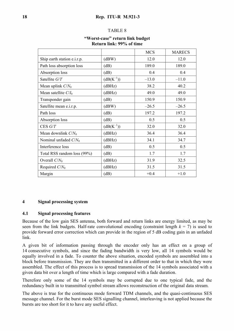
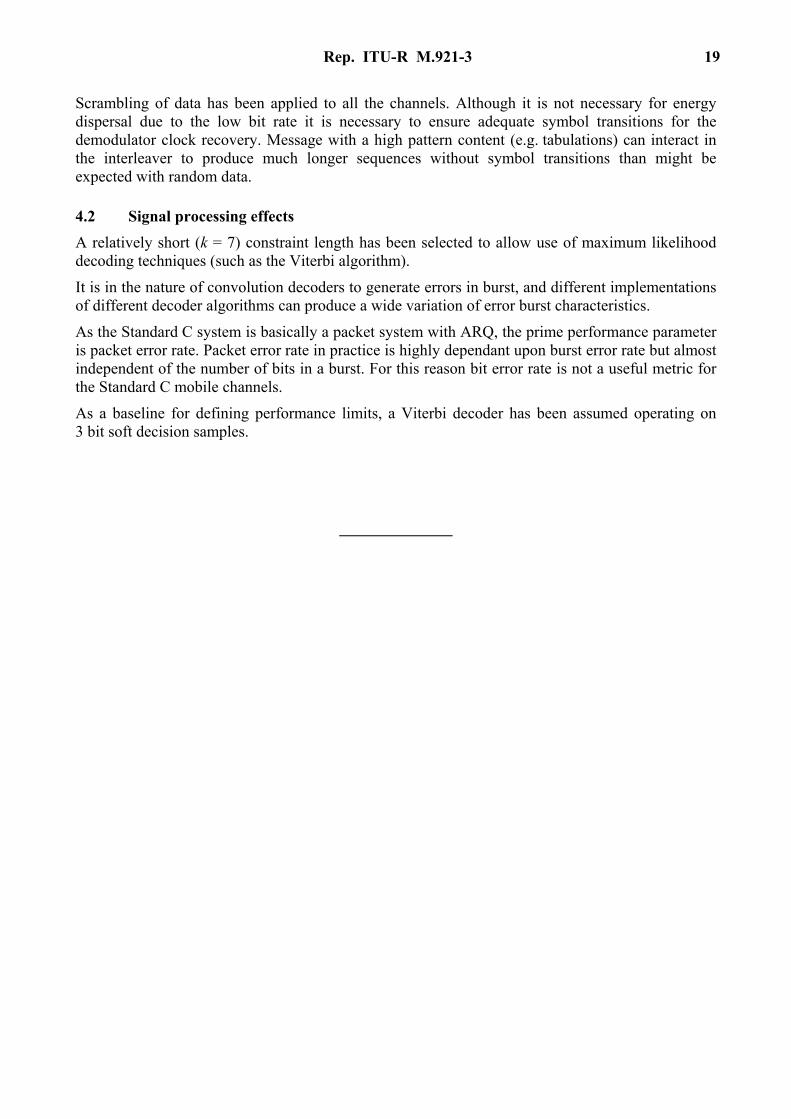
TABLE 8
“Worst-case” return link budget Return link: 99% of time
MCS MARECS Ship earth station e.i.r.p. (dBW) 12.0 12.0 Path loss absorption loss (dB) 189.0 189.0 Absorption loss (dB) 0.4 0.4 Satellite G/T (dB(K–1)) –13.0 –11.0 Mean uplink C/N0 (dBHz) 38.2 40.2 Mean satellite C/I0 (dBHz) 49.0 49.0 Transponder gain (dB) 150.9 150.9 Satellite mean e.i.r.p. (dBW) –26.5 –26.5 Path loss (dB) 197.2 197.2 Absorption loss (dB) 0.5 0.5 CES G/T (dB(K–1)) 32.0 32.0 Mean downlink C/N0 (dBHz) 36.4 36.4 Nominal unfaded C/N0 (dBHz) 34.1 34.7 Interference loss (dB) 0.5 0.5 Total RSS random loss (99%) (dB) 1.7 1.7 Overall C/N0 (dBHz) 31.9 32.5 Required C/N0 (dBHz) 31.5 31.5 Margin (dB) +0.4 +1.0
4 Signal processing system
4.1 Signal processing features Because of the low gain SES antenna, both forward and return links are energy limited, as may be seen from the link budgets. Half-rate convolutional encoding (constraint length k = 7) is used to provide forward error correction which can provide in the region of 5 dB coding gain in an unfaded link.
A given bit of information passing through the encoder only has an effect on a group of 14 consecutive symbols, and since the fading bandwidth is very low, all 14 symbols would be equally involved in a fade. To counter the above situation, encoded symbols are assembled into a block before transmission. They are then transmitted in a different order to that in which they were assembled. The effect of this process is to spread transmission of the 14 symbols associated with a given data bit over a length of time which is large compared with a fade duration.
Therefore only some of the 14 symbols may be corrupted due to one typical fade, and the redundancy built in to transmitted symbol stream allows reconstruction of the original data stream.
The above is true for the continuous mode forward TDM channels, and the quasi-continuous SES message channel. For the burst mode SES signalling channel, interleaving is not applied because the bursts are too short for it to have any useful effect.
Rep. ITU-R M.921-3 19
Scrambling of data has been applied to all the channels. Although it is not necessary for energy dispersal due to the low bit rate it is necessary to ensure adequate symbol transitions for the demodulator clock recovery. Message with a high pattern content (e.g. tabulations) can interact in the interleaver to produce much longer sequences without symbol transitions than might be expected with random data.
4.2 Signal processing effects A relatively short (k = 7) constraint length has been selected to allow use of maximum likelihood decoding techniques (such as the Viterbi algorithm).
It is in the nature of convolution decoders to generate errors in burst, and different implementations of different decoder algorithms can produce a wide variation of error burst characteristics.
As the Standard C system is basically a packet system with ARQ, the prime performance parameter is packet error rate. Packet error rate in practice is highly dependant upon burst error rate but almost independent of the number of bits in a burst. For this reason bit error rate is not a useful metric for the Standard C mobile channels.
As a baseline for defining performance limits, a Viterbi decoder has been assumed operating on 3 bit soft decision samples.