furnace model: cb 140 multi-oil furnaces with cb-125 burner
TRANSCRIPT
WARNING: DO NOT assemble, install, operate, or maintain this equipment without first reading and understanding the information provided in this manual. Installation and
service must be accomplished by qualified personnel. Failure to follow all safety precautions and procedures as stated in this manual may result in property damage, serious personal injury or death.
OPERATOR'S MANUALFURNACE MODEL: CB 140
MULTI-OIL FURNACESwith CB-125 BURNER
IMPORTANT FOR U.S. INSTALLATIONS: All installations must be made in accordance with state and local codes which may differ from the information provided in this manual. Save these instructions for reference.
IMPORTANT FOR CANADIAN INSTALLATIONS: These instructions have been reviewed and accepted by Underwriters' Laboratories of Canada as being appropriate for the installation of the ULC labelled products identified herein. The use of these instructions for the installation of products NOT bearing the ULC label and NOT identified herein may result in an unacceptable or hazardous installation.
IMPORTANT FOR CANADIAN INSTALLATIONS: The installation of this equipment is to be accomplished by qualified personnel and in accordance with the regulation of authorities having jurisdiction and CSA Standard B 139, Installation Code for Oil Burning Equipment.
PUBLICATION DATE: 07/16/13, Rev. 13 CLEAN BURN PART # 43231
I89053-A
USED-OIL BURNINGAPPLIANCE
USED OIL-FIRED FURNACE
LISTED
#MH15393 (N)


Clean Burn, LLC, MANUFACTURER, hereby warrants that MANUFACTURER’s products shall be free from defect in material and workmanship under normal use according to the provisions and limitations herein set forth.
MANUFACTURER warrants the heat exchanger/combustion chamber for a period of ten (10) years or 15,000 hours, whichever comes first), from the date of purchase by the original purchaser, as follows:
If the defect occurs within the first ten (10 years or 15,000 hours, whichever comes first), Clean Burn will replace or repair the heat exchanger/combustion chamber.
MANUFACTURER warrants all other Clean Burn component parts, including the energy retention disk, for a period of one (1) year from the date of purchase by the original purchaser.
LIMITATIONS:The obligation of MANUFACTURER for breach of warranty shall be limited to products manufactured by MANUFACTURER, (1) that are installed, operated and maintained according to MANUFACTURER’s instructions furnished and/or available to the purchaser upon request; (2) that are installed according to all other applicable Federal, State and local codes or regulations; and (3) that the purchaser substantiates were defective in material and workmanship notwithstanding that they were properly installed and correctly maintained as set forth above and were not abused or misused. The MANUFACTURER may request service records or require photos of the installation or defect.
The obligation of MANUFACTURER shall be limited to replacing or repairing the defective product, at the option of the MANUFACTURER. MANUFACTURER shall not be responsible for any labor or costs or removal or reinstallation of its products and shall not be liable for transportation costs to and from its plant at Janesville, Wisconsin.
Use of parts for modification or repair of the product or any component part thereof not authorized or manufactured by MANUFACTURER specifically for such product shall void this warranty.
This warranty shall not apply to any damage to or defect in any of MANUFACTURER’s products that is directly or indirectly caused by (1) force majeure, Act of God or other accident not related to an inherent product defect; or (2) abuse, misuse or neglect of such product, including any damage caused by improper assembly, installation, adjustment, service, maintenance or faulty instruction of the purchaser.
Other than as expressly set forth hereinabove, MANUFACTURER makes no other warranty, express or implied, with respect to any of MANUFACTURER’s products, including but not limited to any warranty of merchantability or fitness for a particular purpose.
And in no event shall MANUFACTURER be responsible for any incidental or consequential damages of any nature suffered by purchaser or any other person or entity caused in whole or in part by any defect in any of MANUFACTURER’s products. Any person or entity to whom this warranty extends and who claims breach of warranty against MANUFACTURER must bring suit thereon within one year from the date of occurrence of such breach of warranty or be forever barred from any and all legal or other remedies for such breach of warranty.
MANUFACTURER is not responsible for and hereby disclaims any undertaking, representation or warranty made by any dealer, distributor or other person that is inconsistent with or in any way more expansive than the provisions of this limited warranty.
WARRANTY INFORMATIONWASTE OIL FURNACE
CLEAN BURN
This warranty grants specific legal rights and shall be read in conformity with applicable state law. In some jurisdictions, the applicable law mandates warranty provisions that provide greater legal rights than those provided for herein. In such case, this limited warranty shall be read to include such mandated provisions; and any provision herein that is prohibited or unenforceable in any such jurisdiction shall, as to such jurisdiction, be ineffective to the extent of such prohibition or unenforceability without invalidating the remaining provisions and without affecting the validity or enforceability of such provision in any other jurisdiction(s).
TRADEMARKS The Clean Burn logo is a trademark of Clean Burn, LLC. All other brand or product names mentioned are the registered trademarks or trademarks of their respective owners.
COPYRIGHTCopyright © 2013 Clean Burn, LLC. All rights reserved. No part of this publication may be reproduced, or distributed without the prior written permission of Clean Burn, LLC. 4109 Capital Circle, Janesville, WI 53546. Subject to change without notice.
Warranty (continued)
TABLE OF CONTENTSSECTION 1: INTRODUCTION .............................................................................................. 1-1 Guide to this Manual ........................................................................................................ 1-1 For Your Safety... .............................................................................................................. 1-2 Guidelines for Furnace Usage ................................................................................... 1-4 Guidelines for Used Oil Tanks ................................................................................... 1-5 Safety Labels ............................................................................................................. 1-6
SECTION 2: UNPACKING ..................................................................................................... 2-1 Removing the Shipping Crate .......................................................................................... 2-1 Unpacking and Inspecting All Components ..................................................................... 2-1 Furnace Component List ........................................................................................... 2-1 Warranty Registration ....................................................................................................... 2-2
SECTION 3: FURNACE ASSEMBLY .............. .................................................................. 3-1 Understanding Assembly .................................................................................................. 3-1 Required Tools and Materials .................................................................................... 3-1 Overview of Furnace Assembly ....................................................................................... 3-2 Installing the Observation Port ......................................................................................... 3-3 Installing the Air Outlet Louvers ...................................................................................... 3-3 Installing the Combustion Sleeve ..................................................................................... 3-5 Installing the Burner ......................................................................................................... 3-6 Checking the Burner Nozzle and Electrodes ............................................................. 3-6 Mounting the Burner on the Hinge Bracket .............................................................. 3-7 Installing the Connector Block, Oil Line Tubing, and Air Line Tubing ........................... 3-8 Installing the Connector Block on the Furnace Door ................................................ 3-8 Installing the Oil Line Tubing .................................................................................... 3-8 Installing the Air Line Tubing .................................................................................... 3-9 Locking the Burner into Firing Position .................................................................... 3-9SECTION 4: FURNACE INSTALLATION ........................................................................... 4-1 Understanding Installation ................................................................................................ 4-1 Typical Installation Illustration .................................................................................. 4-2 Selecting a Location ......................................................................................................... 4-3 Guidelines for Selecting a Location .......................................................................... 4-3 Clearances for Installation ......................................................................................... 4-3 Mounting the Furnace ....................................................................................................... 4-4 Ceiling Mounting ....................................................................................................... 4-4 Raised Platform Mounting ......................................................................................... 4-5 Floor Mounting .......................................................................................................... 4-5 Oil Tank Installation Specifications .................................................................................. 4-7 Installing the Tank Vent and Emergency Vent ........................................................... 4-8 Installing the Metering Pump ........................................................................................... 4-9 Preparing for Installation ........................................................................................... 4-9 Standard Mounting: Vertical Positioning .................................................................. 4-9 Alternate Mounting: Horizontal Positioning .......................................................... 4-11

TABLE OF CONTENTSSECTION 4: FURNACE INSTALLATION (continued) Wiring the Furnace and Pump ........................................................................................ 4-12 Wiring to the Furnace .............................................................................................. 4-12 Wiring to the Metering Pump .................................................................................. 4-12 Installing the Suction Oil Line Components .................................................................. 4-13 Installing the Pressure Relief Oil Line Back to the Tank ............................................... 4-16 Installing the Pressure Oil Line Components ................................................................. 4-17 Installing the Compressed Air Line ................................................................................ 4-17 Installing the Stack ......................................................................................................... 4-18 Installing the Interior Stack ..................................................................................... 4-21 Installing the Barometric Damper ........................................................................... 4-21 Installing the Stack Safety Switch For Canadian Installations ................................ 4-22 Resetting the Stack Safety Switch ..................................................................... 4-23 Understanding the Function of the Stack Safety Switch ................................... 4-23 Installing the Stack Penetration ............................................................................... 4-24 Installing the Exterior Stack .................................................................................... 4-24 Installing the Stack Cap ........................................................................................... 4-24 Installing the Optional Draft Inducer ....................................................................... 4-24 Installing the Wall Thermostat ........................................................................................ 4-26 Replacing the Wall Thermostat Batteries................................................................. 4-26 Inspecting the Furnace Installation ................................................................................. 4-26
SECTION 5: METERING PUMP PRIMING ..................................................................5-1 Understanding Metering Pump Priming ........................................................................... 5-1 Required Tools and Materials .................................................................................... 5-1 Priming the Metering Pump ............................................................................................. 5-2 Vacuum Testing the Oil Pump .......................................................................................... 5-4
SECTION 6: STARTING AND ADJUSTING THE BURNER .......................................6-1 Understanding Burner Startup and Adjustment ................................................................ 6-1 Preparing the Burner for Startup ...................................................................................... 6-1 Starting the Burner ........................................................................................................... 6-2 Checking the Operation of the Fan/Blower Motor ........................................................... 6-4
SECTION 7: RESETTING THE OIL PRIMARY CONTROL ........................................7-1 Understanding the Oil Primary Control ........................................................................... 7-1 Using the Reset Button ..................................................................................................... 7-1 The Blower/Fan Switch .................................................................................................... 7-2 The High Temp Limit Switches ........................................................................................ 7-2 Understanding the L-200 High Temp Limit Switches ............................................... 7-2 Understanding the L-290 Auxiliary Auto Reset High Temp Limit Switch ............... 7-2

TABLE OF CONTENTSSECTION 8: ADJUSTING THE DRAFT OVER FIRE ..................................................8-1 Understanding the Importance of Draft ............................................................................ 8-1 Checking for Correct Draft Over Fire .............................................................................. 8-1 Adjusting the Barometric Damper .................................................................................... 8-2 Solving Draft Over Fire Problems .................................................................................... 8-2 Understanding the Effect of Exhaust Fans on Draft .................................................. 8-3 Checking Draft Over Fire to Determine Severity of Backdraft ................................. 8-3 Installing a Make-up Air Louver ............................................................................... 8-5
SECTION 9: MAINTENANCE ......................................................................................9-1 Understanding Maintenance ............................................................................................. 9-1 Periodic Burner Inspection ............................................................................................... 9-1 Cleaning the Canister Filter .............................................................................................. 9-2 Servicing the Metering Pump ........................................................................................... 9-3 Cleaning the Check Valve / Screen................................................................................... 9-3 Cleaning the Tank ............................................................................................................. 9-4 Cleaning Ash from the Furnace ........................................................................................ 9-5 Annual Burner Tune-Up ................................................................................................... 9-7 End of Season Maintenance ............................................................................................. 9-7 Cleaning and Maintaining the Optional Draft Inducer ..................................................... 9-7
SECTION 10: TROUBLESHOOTING ........................................................................10-1 Flow Chart ...................................................................................................................... 10-2 Troubleshooting Tables .................................................................................................. 10-3
APPENDIX A Detailed Furnace Specifications ...................................................................................... A-1 Burner Technical Specifications ...................................................................................... A-2 Furnace Dimensions ....................................................................................................... A-3 Burner Components ......................................................................................................... A-4 Removing the Nozzle for Cleaning .......................................................................... A-9 CB-140 Cabinet Components ........................................................................................ A-10 Metering Pump Components ......................................................................................... A-12
APPENDIX B Wiring Diagrams ..............................................................................................................B-1 Furnace Wiring Diagram ...........................................................................................B-1 CB-125 Burner Wiring Diagram ...............................................................................B-2 Ladder Schematic ......................................................................................................B-3 Metering Pump Wiring Schematic .............................................................................B-4 CAD Cell Oil Primary Control Data Sheet ................................................................B-5
APPENDIX C Furnace Service Record ....................................................................................................C-1


Operator's Manual: Model CB-140
1-1
SECTION 1: INTRODUCTIONGuide to this Manual
This manual contains all the information necessary to safely install and operate the Clean Burn furnace model CB-140 . Consult the Table of Contents for a detailed list of topics covered. You'll find this manual's step-by-step procedures easy to follow and understand. Should questions arise, please contact your Clean Burn dealer before starting any of the procedures in this manual.
As you follow the directions in this manual, you'll discover that assembling and operating your new furnace involves five basic activities as outlined here: • UNPACKING ..................................................................................................... (Section 2) • ASSEMBLY ........................................................................................................ (Section 3) • INSTALLATION .............................................................................................. (Section 4) • OPERATION • Metering Pump Priming ........................................................................ (Section 5) • Starting and Adjusting the Burner ....................................................... (Section 6) • Resetting the Oil Primary Control ....................................................... (Section 7) • Adjusting the Draft ............................................................................... (Section 8) • MAINTENANCE .............................................................................................. (Section 9)
WARNING!
STOPYOUR SAFETY IS AT STAKE!
DO NOT INSTALL, OPERATE ORMAINTAIN THIS EQUIPMENTWITHOUT FIRST READING
AND UNDERSTANDING THE OPERATOR'S MANUAL!
The manual also contains important and detailed technical reference materials which are located at the back of the manual in the Appendixes.
Please read all sections carefully, including the important safety information found in this section before beginning any installation/operation procedures; doing so ensures your safety and the optimal performance of your Clean Burn furnace.

Operator's Manual: Model CB-140
1-2
For Your Safety...
CAUTION: A safety statement that reminds of safety practices or directs attention to unsafe practices which could result in personal injury if proper precautions are not taken.
WARNING: A strong safety statement indicating that a hazard exists which can result in injury or death if proper precautions are not taken.
DANGER! The utmost levels of safety must be observed; an extreme hazard exists which would result in high probability of death or irreparable serious personal injury if proper precautions are not taken.
In addition to observing the specific precautions listed throughout the manual, the following general precautions apply and must be heeded to ensure proper, safe furnace operation.
DANGER! DO NOT create a fire or explosion hazard by storing or using gasoline or other flammable or explosive liquids or vapors near your furnace.
DANGER! DO NOT operate your furnace if excess oil, oil vapor or fumes have accumulated in or near your furnace. As with any oil burning furnace, improper installation, operation or maintenance may result in a fire or explosion hazard.
WARNING: DO NOT add inappropriate or hazardous materials to your used oil, such as: • Anti-freeze • Carburetor cleaner • Paint thinner • Parts washer solvents • Gasoline • Oil additives • Any other inappropriate/hazardous material
WARNING: Burning chlorinated materials (chlorinated solvents and oils) is illegal, will severely damage your heat exchanger, immediately void your warranty, and adversely affect the proper, safe operation of your furnace. Instruct your personnel to never add hazardous materials to your used oil.
For your safety, Clean Burn documentation contains the following types of safety statements (listed here in order of increasing intensity). Note the safety key words printed in bold for each:
• NOTE: A clarification of previous information or additional pertinent information.
• ATTENTION: A safety statement indicating that potential equipment damage may occur if instructions are not followed.

Operator's Manual: Model CB-140
1-3
For Your Safety... (continued)WARNING: Never alter or modify your furnace without prior written consent of Clean Burn, LLC. Unauthorized modifications or alteration can adversely affect the proper, safe operation of your furnace.
WARNING: The burner which is shipped with your Clean Burn furnace is to be used only with your furnace according to the instructions provided in this manual. DO NOT use the burner for any other purpose!
WARNING: The Best Operator is a Careful Operator! By using common sense, observing general safety rules, and adhering to the precautions specific to the equipment, you, the operator, can promote safe equipment operation. Failure to use common sense, observe general safety rules, and adhere to the precautions specific to the equipment may result in equipment damage, fire, explosion, personal injury and/or death.
WARNING: The installation, operation, and maintenance of this equipment in the U.S. must be accomplished by qualified personnel and in compliance with the specifications in the Clean Burn Operator's Manual and with all national, state, and local codes or authorities having jurisdiction over environmental control, building inspection and fuel, fire and electrical safety and the following standards: NFPA 30 Flammable and Combustible Liquids Code NFPA 30A Automotive and Marine Service Station Code NFPA 31 Standard for the Installation of Oil Burning Equipment NFPA 211 Chimneys, Fireplaces, Vents and Solid Fuel Burning Appliances NFPA 88A Parking Structures NFPA 88B Repair Garages NFPA 70 National Electrical Code
The International Mechanical Code The International Building Code The International Fire Code The International Fuel Gas Code Likewise, the installation, operation, and maintenance of this equipment in Canada is to be accomplished by qualified personnel and in compliance with the specifications in the Clean Burn Operator's Manual and in accordance with the regulation of authorities having jurisdiction and the following CSA Standards:
B139 Installation Code for Oil Burning Equipment B140.0 General Requirements for Oil Burning Equipment C22.1 Canadian Electrical Code, Part 1.
Failure to comply with these standards and requirements may result in equipmentdamage, fire, explosion, personal injury and/or death.

Operator's Manual: Model CB-140
1-4
Guidelines for Furnace Usage
n This furnace is listed for commercial and/or industrial use only; it is not listed for residential use. n This furnace is listed with Underwriters Laboratory and Underwriters' Laboratories of Canada to burn the following fuels: • #2 fuel oil • Used crankcase oil up to 50 SAE • Used hydraulic oil • Used transmission fluid (U.S.) • #4 and #5 fuel oil (U.S.)
n Make sure you comply with all EPA regulations concerning the use of your furnace. EPA regulations require that: • Your used oil is generated on-site. You may also accept used oil from "do-it-yourself" oil changers. • Hazardous wastes, such as chlorinated solvents, are NOT to be mixed with your used oil. • The flue gases are vented to the outdoors with an appropriate stack. • Your used oil is recycled as fuel for "heat recovery". DO NOT operate your furnace in warm weather just to burn oil.
Contact your Clean Burn dealer for current EPA regulations.
n If your furnace ever requires service, call your Clean Burn dealer. DO NOT allow untrained, unauthorized personnel to service your furnace. Make sure that your furnace receives annual preventative maintenance to ensure optimal performance.
For Your Safety... (continued)

Operator's Manual: Model CB-140
1-5
For Your Safety... (continued)
Guidelines for Used Oil Tanks
For the safe storage of used oil and the safety of persons in the vicinity of the used oil supply tank, ensure that your tank installation adheres to the following safety guidelines:
• The tank installation must meet all national and local codes. Consult your local municipal authorities for more information as necessary. • Review and adhere to the safety guidelines for used oil supply tanks as stated in the WARNING shown. • Ensure that the tank for your furnace installation complies with all code and safety requirements as stated here. If the tank does not comply, DO NOT use it. • If you do not have a copy of the tank safety label pictured at right, please contact your Clean Burn dealer for the label, which is to be affixed directly on your used oil supply tank.
Follow all instructionsfor tank installation inOperator's Manual.
ONLY place these listed substances inthis used-oil supply tank:• Used crankcase oil• Used automatic transmission fluid• Used hydraulic oil• #2 fuel oilDo NOT place flammable or corrosivesubstances such as gasoline, chlorinatedoils, solvents, paint thinners, or any otherunsafe substances in this used-oil supply tank.
Do NOT weld or allow open flame within35 feet of this used-oil supply tank.
Tank installation MUST comply with NFPA30 and 31 Fire Codes, including the followingrequirements:• Tank must be listed to UL 80 or UL 142.• Tank must be vented to outside.• Emergency vent or explosion relief mustbe installed on tank.• Inside fill allowed only with funnel including 1/4turn-to-close fall valve, which must beclosed after filling.• All other openings must be plugged• All oil lines must be constructed of copper,steel, or brass components. Do NOT userubber or plastic tubing or piping, or any otherinappropriate material.
42366 Rev. 2
Fire and explosion hazardsTo prevent serious injury or death:
WARNING

Operator's Manual: Model CB-140
1-6
I89083-A
DATECODE
42367
42030
4202742358 4245742318
42319AIR OIL
For Your Safety... (continued)Safety Labels
CB-140 Furnace Cabinet Labels
Label Part # Description42319 CB-140 Name Label42367 Furnace Safety Warning Label (Multiple Messages - Fire/Shock/Burn Hazards)42318 CB-140 UL Data Label42358 UL Header Label42457 Made in USA / Patent Pending Combination Label42030 Furnace Electrical Shock Hazard Warning Label (additional label may be included, not shown, on top near fan) 42068 Fan Entanglement Hazard Warning Label (not shown, on top near fan)42027 Burn Hazard / Hazardous Voltage Warning Label
Following are the locations and descriptions of all labels on your Clean Burn furnace. The following illustrations show the location of labels on your furnace. Please note that some labels denote model number, model description, etc. while others contain important safety messages.
Each Safety Label contains an important safety message starting with a key word as discussed earlier in this section (e.g. ATTENTION, CAUTION, WARNING, DANGER). For your safety and the safe operation of your furnace, review all labels and heed all safety messages as printed on the labels.
If any labels on your Clean Burn furnace ever become worn, lost or painted over, please call your Clean Burn dealer for free replacements.

Operator's Manual: Model CB-140
1-7
For Your Safety... (continued)
CB-140 Furnace Cabinet Safety Labels
To avoid possible injury, death, or equipment damage, read and understand operator's manuals and all safety precautions before installing, operating, or servicing this equipment.
WARNINGFire, explosion and burn hazards:
Maintain clearances fromcombustibles as listed on unit.ONLY burn used crankcaseoil, automatic transmission�uid, hydraulic oil, or #2 fueloil. NEVER burn any othersubstances in this unit.
Hot gases and ash may be released wheninspection port is opened.
Wear safety goggles and hand protectionwhen opening inspection port.Keep face away and open port slowly.
•
•
42367 Rev. 2
42030 Rev. 2
Hazardous voltage.To prevent serious injury, shut OFF main power to unit before removing cover.
Line voltage is present on mostsubbase terminals when power is ON.If the furnace is not wired correctly.�re, shock or damage could result.
ONLY a quali�ed electrician should wire this furnace.ONLY use copper conductors.
•
•
WARNING
Blower can start at any time.Turn power OFF before servicing.Do NOT operate without guard in place.
Entanglement and cutting hazard.
42068 Rev. 2
WARNING
Burner may �re at any time.Disconnect burner power cordbefore swinging open burneror clean-out door.
Burn Hazard.Hazardous Voltage.
WARNING
42027 Rev. 2

Operator's Manual: Model CB-140
1-8
For Your Safety... (continued)
CB-140 Furnace Cabinet Safety Labels
HYDRAULIC OILUSED CRANKCASE OIL
NO 5 OIL
ATF NO 4 OIL
LISTED FUELS
NO 2 OIL
MODEL NO.
1.0 N/A
1.0
1.0
1.0
1.0
N/A
N/A
1.0
1.0
16 2.5
2.0
2.0
2.5
2.5
16
14
14
14
-PSIG-
ATOM AIRPRESSURE
-GPH-
1.0
ULINPUT
-GPH-
1.0
ULCINPUT
CB-140
OILPRESSURE
1.5
-PSIG-
14
140000
MAX. DISCHARGEAIR TEMP (°F)
CLEARANCE TO COMBUSTIBLE SURFACES: (INCHES)
TOP
FRONT 48
12
BOTTOM W/AIR DIFFUSER
CHIMNEY
REAR
30
12
18 12
60
FLUE DRAFT(INCHES OF W.C.)200 -0.06
TOTAL CIRCUIT AMPACITY
MAXIMUM FUSE SIZE
BURNER HEATER WATTS
AIR COMPRESS. (OPT) HP.
DRAFT IND. (OPT) HP
42318 - R1
1/10
1/3
280
120
120
120
12.5
20
60
60
601.0
4.0
2.4
OIL PUMP MOTOR HP.
BURNER MOTOR HP.
FAN MOTOR HP.
1/10
1/20
POWER
1/4
120
120
VOLTS
120
HZ
60
60
601.2
0.6
AMPS
3.2
BURNER REQUIRES A MINIMUM AIR SOURCE OF 2 S.C.F.M. AT 25 P.S.I.
THIS APPLIANCE IS NOT TO BE USED WITH AIR FILTERS AND SHALL INCORPORATE NO PROVISIONS FOR MOUNTING AIR FILTERS.
INSTALL AND USE ONLY IN ACCORDANCE WITH THE MFR'S INSTALLATION AND OPERATING INSTRUCTIONS. FOR COMMERCIAL OR INDUSTRIAL USE ONLY.
AUTHORITIES HAVING JURISDICTION SHOULDBE CONSULTED PRIOR TO INSTALLATION.
NOMINAL INPUT RATING W/NO 2 FUEL OIL (BTU/HR)
SIDE
BOTTOM W/OAIR DIFFUSER
CLEAN BURN LLCJANESVILLE, WISCONSIN (USA)
MH15393
13084NO.
USED-OIL BURNING APPLIANCE USED OIL-FIRED FURNACEUSED OIL-FIRED BOILER
For use with Integral Primary Safety Control
MULTI-OIL HEATING SYSTEM
INSTALL AND USE ONLY IN ACCORDANCE WITH THE MFR’S INSTALLATION AND OPERATING INSTRUCTIONS.FOR COMMERCIAL OR INDUSTRIAL USE ONLY.
CERTIFIED TO ELECTRICAL AND FUEL BURNING REQUIREMENTS ONLY.42358
AUTHORITIES HAVING JURISDICTION SHOULDBE CONSULTED PRIOR TO INSTALLATION.
LISTED

Operator's Manual: Model CB-140
1-9
FRONT VIEW
TOP VIEWI89084-C
RH SIDE VIEWLH SIDE VIEW
42005
42000
42520
42004
42235
42519
42023
42457
For Your Safety... (continued)
CB-125 Burner Labels
Label Part # Description42000 Reset Warning Label42004 Voltage / Moving Parts Warning Label42005 Serviced-By Label42023 Power / Pump Label42235 Burner Warning Label42457 Made In USA Label42520 CB-140 Series Logo Label42519 CB-140 Series Serial Number Plate
CB-125 Burner Safety Labels
Fire and explosion hazard.Do NOT press reset button untilyou read and understand ResetProcedures in Operator's Manual.
42000 Rev. 2
WARNINGHazardous high voltageand moving parts hazard.
To avoid electric shock and injuryfrom moving parts. turn power OFFbefore opening cover.
WARNING
42004 Rev. 2
42235 Rev. 2
Fire and explosion hazard.This burner is to be installed ONLY on Clean Burn products.Only a quali�ed technician may maintain and service this burner.
WARNING

Operator's Manual: Model CB-140
1-10

Operator's Manual: Model CB-140
2-1
SECTION 2: UNPACKINGBefore assembling your furnace, you must accomplish the following activities described in this section: • Removing the Shipping Crate • Unpacking and Inspecting All Components • Warranty Registration
Removing the Shipping CrateNOTE: Remove the shipping crate prior to assembly and installation of the furnace. DO NOT use the crate as a platform for furnace installation!1. Carefully remove the top boards of the shipping crate. Then remove the front, back, and side panels of the shipping crate.2. Carefully lift the furnace off the shipping pallet with a fork lift. ATTENTION: DO NOT attempt to slide the furnace cabinet out of the shipping crate--you may damage the furnace cabinet.
Unpacking and Inspecting All ComponentsFollowing is an itemized list of all components you should have received in your Clean Burn furnace shipment. Open all shipping containers and inspect all components according to the list. Immediately notify the freight company and your Clean Burn dealer in case of shipping damage or shortage(s). Keep all components together so you will have them as needed for furnace assembly and installation. Furnace Component List
ONE SKID containing: • Furnace cabinet • Items packed inside furnace cabinet (combustion chamber): NOTE: Please refer to the procedure on the following page to remove these items. • Louvers • Furnace Accessories (items below in one box): • Canister Filter • Vacuum Gauge • Check Valve and Check Valve Screen • Wall Thermostat • Barometric Damper • Connector Block • Burner Oil Line and Air Line Components • Assorted bolts/fittings for assembly/installation of furnace components • Operator's Manual Literature Packet (includes Tank Safety Label) ITEMS PACKED IN INDIVIDUAL BOXES: • Burner • Combustion Sleeve • Metering Pump (includes Suction Oil Line Fittings Package)NOTE: You may have received additional boxes or skids if you ordered optional accessories.

Operator's Manual: Model CB-140
2-2
Warranty Registration
For proper warranty registration, Clean Burn requires that you fill out the provided warranty registration card and return it within 30 days to:
CLEAN BURN WARRANTY REGISTRATIONClean Burn, LLC.
4109 Capital CircleJanesville, WI 53546
Unpacking Items Packed Inside the Furnace
To unpack the items packed inside the furnace cabinet (in the combustion chamber), you will need to open the combustion chamber door.
Figure 2A - Accessing the Combustion Chamber
1. Remove the three nuts which hold the combustion chamber door closed. Set the nuts aside in a safe place for later re-installation after the combustion sleeve has been installed (Section 3).
2. Carefully swing the combustion chamber door open. Remove and inspect the components packed inside.
3. Leave the door unfastened (open) for assembly/installation procedures to be accomplished in the next section.
I89085

Operator's Manual: Model CB-140
3-1
SECTION 3: FURNACE ASSEMBLYUnderstanding AssemblyAssembling your Clean Burn Furnace includes the following steps: (1) Installing the Observation Port (2) Installing the Louvers (3) Installing the Combustion Sleeve (4) Installing the Burner (5) Installing the Connector Block, Oil Line Tubing, and Air Line Tubing
Clean Burn recommends that you review all assembly procedures before proceeding, paying careful attention to safety information statements.
Figure 3A on the following page provides a general overview of the furnace components and their proper assembly.
Required Tools and Materials
The following tools are required for furnace assembly and should be gathered before starting any procedures:
• 9/16" open-end wrench • Medium flat-blade screwdriver • Medium adjustable wrench • 1/4" nut driver attachment for drill • 5/16" nut driver attachment for drill • Variable speed drill

Operator's Manual: Model CB-140
3-2
Complete assembly of the furnace according to the following list of activities as illustrated above: (1) Installing the Observation Port (2) Installing the Louvers (3) Installing the Combustion Sleeve (4) Installing the Burner (5) Installing the Connector Block, Oil Line Tubing, and Air Line Tubing
NOTE: Corresponding procedures provided in order in this section.
Figure 3A - Overview of Furnace Assembly
I89086-A
2
3 COMBUSTION SLEEVEINSTALLED IN CHAMBERON 2" X 2" BLOCKS
LOUVERS
4
BURNERMOUNTINGBRACKET
4
"ALL THREAD" RODS
1 OBSERVATIONPORT
5CONNECTORBLOCK

Operator's Manual: Model CB-140
3-3
Installing the Observation Port CAUTION: To prevent serious personal injury, the observation port must be correctly installed according to the following procedure. A properly installed observation port permits safe obser-vation of the flame during furnace operation. Be sure to follow all safety procedures as outlined in this manual when observing the flame through the port.
1. Refer to Figure 3B.2. Use a 1/4" nut driver to remove the two (2) self-tapping screws from the half-moon piece.3. Position the half-moon piece and the faceplate on the observation port, and install the two self-tapping screws.4. Open the port and make sure the faceplate moves and closes freely. If the faceplate hangs up, loosen the hex-head screws slightly until the faceplate closes correctly.
Figure 3B - Assembly of Observation Port
Installing the Air Outlet LouversAir Flow Discharge Installation Guidelines:
• It is very important to properly install the louvers to direct the flow of hot air away from the furnace The air flow may be directed front, back, or to either side depending on how the louvers are installed.
• Note that each furnace is supplied with four (4) louvers which may be installed all in the same direction OR the louvers may be split for partial air discharge out either side or front to back.
• When determining the placement of the air discharge louvers, you also need to consider the required clearances from combustibles as stated in Section 4 of this manual.
• DO NOT restrict the flow of the hot air from the furnace by keeping the louvers completely closed, or the furnace may not operate properly.
HALF-MOONPIECE
FACE
OBSERVATIONPORT
PLATE
I89087
Operator's Manual: Model CB-140
3-4
Installing the Air Outlet Louvers (continued)
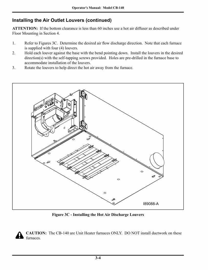
Figure 3C - Installing the Hot Air Discharge Louvers
ATTENTION: If the bottom clearance is less than 60 inches use a hot air diffuser as described under Floor Mounting in Section 4.
1. Refer to Figures 3C. Determine the desired air flow discharge direction. Note that each furnace is supplied with four (4) louvers.
2. Hold each louver against the base with the bend pointing down. Install the louvers in the desired direction(s) with the self-tapping screws provided. Holes are pre-drilled in the furnace base to accommodate installation of the louvers.
3. Rotate the louvers to help direct the hot air away from the furnace.
CAUTION: The CB-140 are Unit Heater furnaces ONLY. DO NOT install ductwork on these furnaces.
I89088-A

Operator's Manual: Model CB-140
3-5
Installing the Combustion Sleeve
Installing the Combustion Sleeve Inside the Combustion Chamber
ATTENTION: DO NOT fire your furnace without the Combustion Sleeve in place, or poor flame retention will occur. Handle the Combustion Sleeve carefully to avoid damage.
1. Refer to Figure 3A and 3D to review the proper position of the Combustion Sleeve and 2" x 2" mounting Blocks.
2. Swing open the clean-out door on the front of the furnace to gain access to the combustion chamber.
3. Refer to Figure 3D. Place the two (2) soft fiber board blocks (2" x 2" x 8") on the bottom of the combustion chamber against the indicator tabs. The notch in the support blocks should fit over the front flue plate.
4. Gently set the Combustion Sleeve on top of the two Blocks. The combustion sleeve needs to seat firmly against the door insulation for proper combustion. Carefully position the Combustion Sleeve on the blocks so that it extends out slightly beyond the door opening. The door will push the Combustion Sleeve in place as it is closed.
Closing the Furnace Door
1. After the Combustion Sleeve has been installed, close the furnace clean-out door.2. If necessary, loosen the door hinges to allow the door to seal tight. 3. Tighten the three (3) lock-down nuts until all are snug.
Figure 3D - Installing the Combustion Sleeve
I89090
COMBUSTION SLEEVETIGHT AGAINST FRONTDOOR INSULATIONSUPPORT BLOCK
LOCATION INDICATOR TABNOTCH IN SUPPORT BLOCKOVER FRONT FLUE PLATE

Operator's Manual: Model CB-140
3-6
Figure 3E - Burner Nozzle and Electrode Specifications
Installing the Burner
Checking the Burner Nozzle and Electrodes
NOTE: The burner nozzle is factory installed. Both furnace models use a Delavan 9-5 nozzle. The nozzle size is indicated on the nozzle as shown in Figure 3E. Refer also to Appendix A at the back of the manual for additional specifications/instructions on the burner nozzle.
ATTENTION: Check the electrode settings as specified in Figure 3E. The electrode settings must be correct for your burner to operate properly.
BURNER NOZZLE
NOZZLE IS STAMPEDEITHER 9-5 OR -5 ON
FLAT OF NOZZLE HEAD
SIDE VIEW - AA
3/16" GAP BETWEENELECTRODES & NOZZLE
CRITICAL DIMENSION:NOZZLE MUST BE 1/8"
AHEAD OF THE DISK.NOZZLE MUST NOT BE
BEHIND THE DISK.
1/8"SPARK
GAP
VIEW - AA
VIEW - BB
3X
I88340-B
SIDE VIEW - BB
Operator's Manual: Model CB-140
3-7
Installing the Burner (continued)
Mounting the Burner on the Hinge Bracket
ATTENTION: Burner tube components (e.g. electrodes and retention head) are factory set. Handle the burner with extreme care so that burner components are not damaged.1. Remove the nut from the mounting flange of the furnace cabinet, and set it aside for later use.2. Lift the burner into position so that it is mounted on the hinge bracket on the furnace cabinet.3. Carefully swing the burner so the retention head enters the throat of the furnace.4. Check the clearance between the retention head and the furnace throat. There must be at least 1/8"clearance,sotheretentionheadisnot"bumped"asyouswingtheburnerintofiring position. NOTE: If the retention head "bumps" the furnace throat, adjust the hinge bracket bolts as follows: • While supporting the burner, slightly loosen the two (2) hinge bracket bolts. • Carefully re-position the burner so it swings freely into its firing position. • With the burner in its firing position, re-tighten the hinge bracket bolts.
Operator's Manual: Model CB-140
3-8
SIDE VIEW OF FURNACESHOWING OIL LINE INSTALLED I89089-A
AIR OIL
CONNECTOR BLOCK
ON BURNEROIL FITTING
OIL LINE
ASSEMBLYSWIVEL
CONNECTOR BLOCK
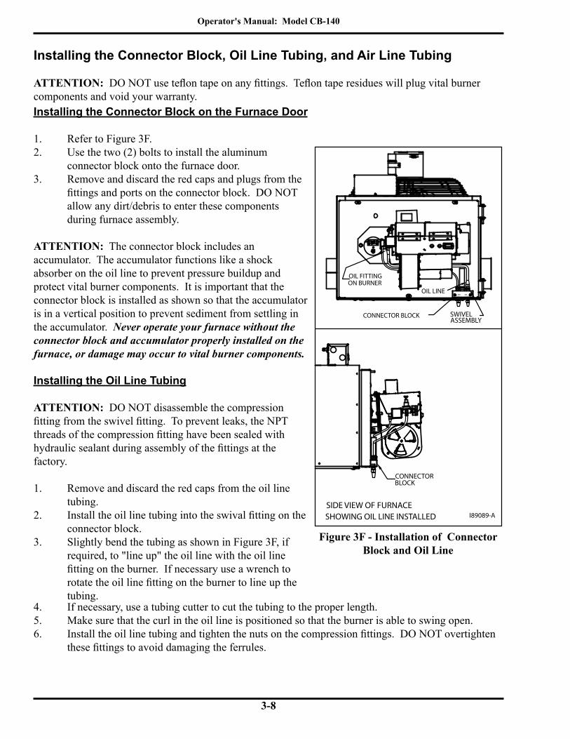
Installing the Connector Block, Oil Line Tubing, and Air Line Tubing
ATTENTION: DO NOT use teflon tape on any fittings. Teflon tape residues will plug vital burner components and void your warranty.
Figure 3F - Installation of Connector Block and Oil Line
Installing the Connector Block on the Furnace Door
1. Refer to Figure 3F.2. Use the two (2) bolts to install the aluminum connector block onto the furnace door.3. Remove and discard the red caps and plugs from the fittings and ports on the connector block. DO NOT allow any dirt/debris to enter these components during furnace assembly.
ATTENTION: The connector block includes anaccumulator. The accumulator functions like a shock absorber on the oil line to prevent pressure buildup and protect vital burner components. It is important that the connector block is installed as shown so that the accumulator is in a vertical position to prevent sediment from settling in the accumulator. Never operate your furnace without the connector block and accumulator properly installed on the furnace, or damage may occur to vital burner components.
Installing the Oil Line Tubing
ATTENTION: DO NOT disassemble the compression fitting from the swivel fitting. To prevent leaks, the NPT threads of the compression fitting have been sealed with hydraulic sealant during assembly of the fittings at the factory.
1. Remove and discard the red caps from the oil line tubing.
2. Install the oil line tubing into the swival fitting on the connector block.
3. Slightly bend the tubing as shown in Figure 3F, if required, to "line up" the oil line with the oil line fitting on the burner. If necessary use a wrench to rotate the oil line fitting on the burner to line up the tubing.
4. If necessary, use a tubing cutter to cut the tubing to the proper length.5. Make sure that the curl in the oil line is positioned so that the burner is able to swing open.6. Install the oil line tubing and tighten the nuts on the compression fittings. DO NOT overtighten
these fittings to avoid damaging the ferrules.

Operator's Manual: Model CB-140
3-9
Installing the Connector Block, Oil Line Tubing, and Air Line Tubing(continued)Installing the Air Line Tubing
7. Remove and discard the red caps from the air line tubing.8. Push the air line tubing into the push fitting on the connector block until the tubing bottoms out
in the fitting. 9. Repeat this procedure to connect the air line tubing to the air line fitting on the the burner.
Locking the Burner into Firing Position
10. Swing the burner into firing position.11. Install and tighten the lock-down nut on the mounting plate bolt to secure the burner in its firing
position.12. Plug the burner electrical cable into the receptacle on the top of the burner housing.13. Tighten the locking ring to secure the electrical cable.
NOTE: Be sure to properly align the plug when plugging it into the receptacle. See Fig 3G.
Figure 3G - Detail of Burner Electric Receptacle
NOTE: Your furnace is now assembled and ready for installation. Install the furnace as soon as possible so the burner and/or fan are not "bumped" or damaged. If you must store the furnace for a period of time before installation, make sure it is located in a safe, secure area.
CONNECTOR PLUG
KEY IN PLUGMUST ALIGNWITH SLOT INRECEPTACLE
RECEPTACLE ONTOP OF BURNER
I88641-B

Operator's Manual: Model CB-140
3-10

Operator's Manual: Model CB-140
4-1
SECTION 4: FURNACE INSTALLATIONUnderstanding InstallationInstalling your Clean Burn furnace is a multi-step process which includes: (1) Selecting a Location (6) Installing the Oil Lines (2) Mounting the Furnace (7) Installing the Compressed Air Line (3) Oil Tank Specifications (review) (8) Installing the Stack (4) Installing the Metering Pump (9) Installing the Wall Thermostat (5) Wiring the Furnace and Pump (10) Inspecting the Installation Clean Burn recommends that you review all procedures before beginning installation, paying careful attention to safety information statements. Figure 4A and 4B provide a general overview of a typical furnace installation and should be reviewed closely before proceeding.
WARNING: The installation, operation, and maintenance of this equipment in the U.S. must be accomplished by qualified personnel and in compliance with the specifications in the
Clean Burn Operator's Manual and with all national, state, and local codes or authorities having jurisdiction over environmental control, building inspection and fuel, fire and electrical safety and the following standards of the National Fire Protection Association. NFPA 30 Flammable and Combustible Liquids Code NFPA 30A Automotive and Marine Service Station Code NFPA 31 Standard for the Installation of Oil Burning Equipment NFPA 211 Chimneys, Fireplaces, Vents and Solid Fuel Burning Appliances NFPA88A Parking Structures NFPA 88B Repair Garages NFPA 70 National Electrical Code
Likewise, the installation, operation, and maintenance of this equipment in Canada is to be accomplished by qualified personnel and in compliance with the specifications in the Clean Burn Operator's Manual and in accordance with the regulation of authorities having jurisdiction and the following CSA Standards:
B139 Installation Code for Oil Burning Equipment B140.0 General Requirements for Oil Burning Equipment C22.1 Canadian Electrical Code, Part 1
Failure to comply with these standards and requirements may result in equipment damage, fire, explosion, personal injury and/or death.
WARNING: Improper installation can adversely affect the proper, safe operation of your furnace. It is critical that your furnace installer reads and follows the instructions provided in
this manual.
Operator's Manual: Model CB-140
4-2
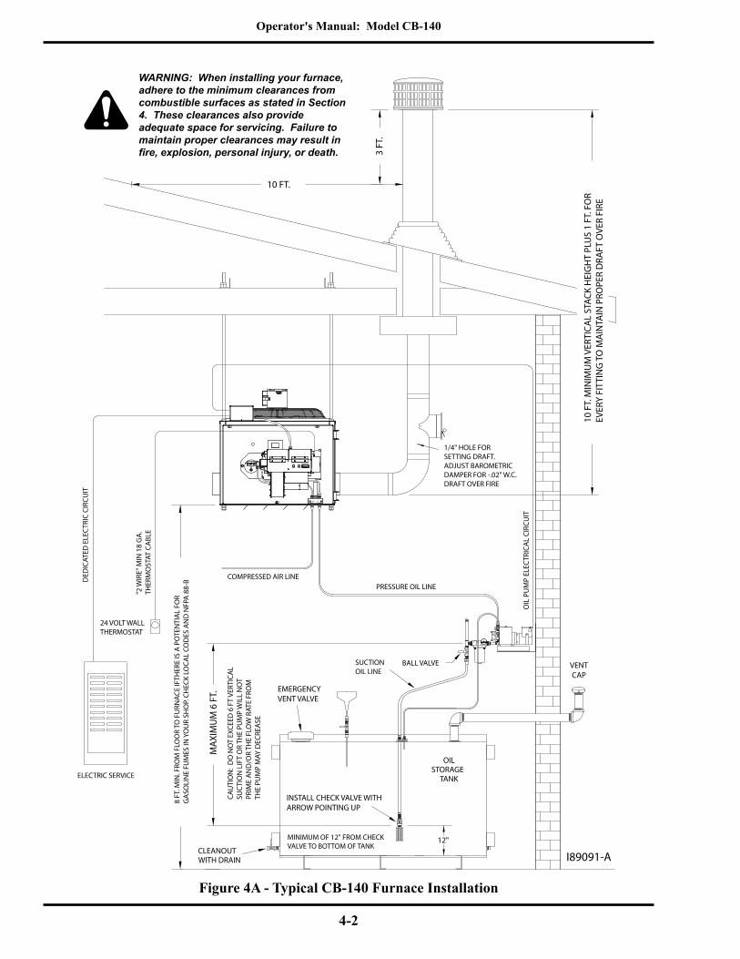
Figure 4A - Typical CB-140 Furnace Installation
SUCTIONOIL LINE
I89091-A
COMPRESSED AIR LINE
CAU
TIO
N:
DO
NO
T EX
CEED
6 F
T VE
RTIC
AL
SUC
TIO
N L
IFT
OR
THE
PUM
P W
ILL
NO
TPR
IME
AN
D/O
R TH
E FL
OW
RAT
E FR
OM
THE
PUM
P M
AY D
ECRE
ASE
8 FT
. MIN
. FRO
M F
LOO
R TO
FU
RNAC
E IF
THER
E IS
A P
OTE
NTI
AL
FOR
GA
SOLI
NE
FUM
ES IN
YO
UR
SHO
P. CH
ECK
LOCA
L CO
DES
AN
D N
FPA
88-
B10 FT.
BALL VALVE
MAX
IMU
M 6
FT.
VENTCAP
EMERGENCYVENT VALVE
CLEANOUTWITH DRAIN
OILSTORAGE
TANK
PRESSURE OIL LINE
ELECTRIC SERVICE
DED
ICAT
ED E
LEC
TRIC
CIR
CUIT
OIL
PU
MP
ELEC
TRIC
AL
CIRC
UIT
24 VOLT WALLTHERMOSTAT
"2 W
IRE"
MIN
18
GA
.TH
ERM
OST
AT C
ABL
E
1/4" HOLE FORSETTING DRAFT.ADJUST BAROMETRICDAMPER FOR -.02" W.C.DRAFT OVER FIRE
3 FT
.
INSTALL CHECK VALVE WITHARROW POINTING UP
12"MINIMUM OF 12" FROM CHECKVALVE TO BOTTOM OF TANK
AIR OIL
WARNING: When installing your furnace, adhere to the minimum clearances from combustible surfaces as stated in Section 4. These clearances also provide adequate space for servicing. Failure to maintain proper clearances may result in fire, explosion, personal injury, or death.
10 F
T. M
INIM
UM
VER
TICA
L ST
ACK
HEI
GH
T PL
US
1 FT
. FO
REV
ERY
FITT
ING
TO
MA
INTA
IN P
ROPE
R D
RAFT
OVE
R FI
RE

Operator's Manual: Model CB-140
4-3
Selecting a LocationGuidelines for Selecting a Location
The location you select for your furnace must allow the following: • Unobstructed, even heat distribution. • Safe, easy access for servicing. • Unobstructed passage for shop vehicles and equipment. • Proper clearances from combustibles. Verify according to your local safety codes. • Adequate combustion air per local codes. • Proper stack installation.
WARNING: Codes may require that your furnace is mounted a minimum of eight (8) feet off the ground when installing the furnace in a repair facility. Refer to NFPA-88B, Standard for Repair Garages, Chapter 3, Hazards, Sec. 3-2.3.1.
CLEARANCES FOR INSTALLATION
• TOP (of furnace) .............................. 12"• FRONT (burner) ............................... 48"• SIDE (with or without stack) ............. 12"• CHIMNEY CONNECTOR ................ 18"• REAR .............................................12"• BOTTOM (with air diffuser) .............. 30"• BOTTOM (without air diffuser) ......... 60"
Figure 4B - Clearances from Combustibles
NOTE: See Appendix A for furnace cabinet dimensions.
WARNING: Adhere to the following minimum clearances from combustible surfaces and to provide adequate clearance for servicing (also refer to Figure 4B for visual reference); failure to maintain proper clearances may result in fire, explosion, personal injury or death.
I89065-A
12 "REAR
12 "TOP
18 "CHIMNEY
CONNECTOR
48 "FRONT
18 "SIDE
• 96 " BOTTOM - IF THERE IS POTENTIAL FOR GASOLINE FUMES
• 60 " BOTTOM - IF THERE IS NO POTENTIAL FOR GASOLINE FUMES
• 30 " BOTTOM - IF THERE IS NO POTENTIAL FOR GASOLINE FUMES AND A HOT AIR OUTLET DIFFUSER IS USED
MINIMUM CLEARANCESCB-140 FURNACE

Operator's Manual: Model CB-140
4-4
Mounting the FurnaceAfter selecting a safe and appropriate location for your furnace, construct the mounting system as required by the location and the following specifications.
Ceiling Mounting
WARNING: To prevent serious personal injury, ensure that your furnace mounting system can safely bear the suspended weight of the furnace and allow safe servicing of furnace components.
Use adequately sized square tubing or angle iron bridged across sufficient structural members to safely support the furnace.
1. Refer to Figure 4C.2. Follow the instructions as provided in the diagram.3. Use a spirit level to make sure the cabinet is level side to side and front to back.
Figure 4C - Ceiling Mounting Installation Overview
I89092-A
ANGLE IRON SUPPORT BEAMS
DOUBLENUTS
CEILING MOUNTING SYSTEMWARNING! USE MINIMUM 2-1/2 X 2-1/2 X 1/4" ANGLEIRON BEAMS, BRIDGED ACROSS SUFFICIENTSTRUCTURAL MEMBERS TO SAFELYSUPPORT FURNACE
SUPPORT RODS(4) 1/2" or 5/8 "ALL THREAD"
INSERT SUPPORT RODS THROUGHTHE FURNACE CABINET ANDINSTALL A WASHER AND DOUBLENUTS ON THE BOTTOM
WARNING! MAKE SURE TO USEDOUBLE NUTS ON BOTH TOPAND BOTTOM OF THE"ALL THREAD" RODS
CABINET TO INCREASE STABILITY
A NUT AND WASHER CAN BEPLACED ABOVE THE FURNACE
AIR OIL
Operator's Manual: Model CB-140
4-5
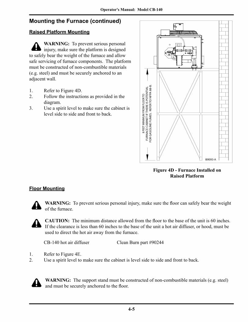
Raised Platform Mounting
WARNING: To prevent serious personal injury, make sure the platform is designed
to safely bear the weight of the furnace and allow safe servicing of furnace components. The platform must be constructed of non-combustible materials (e.g. steel) and must be securely anchored to an adjacent wall.
1. Refer to Figure 4D.2. Follow the instructions as provided in the
diagram.3. Use a spirit level to make sure the cabinet is
level side to side and front to back.
Mounting the Furnace (continued)
Figure 4D - Furnace Installed onRaised Platform
WARNING: The support stand must be constructed of non-combustible materials (e.g. steel) and must be securely anchored to the floor.
CB-140 hot air diffuser Clean Burn part #90244 1. Refer to Figure 4E.2. Use a spirit level to make sure the cabinet is level side to side and front to back.
WARNING: To prevent serious personal injury, make sure the floor can safely bear the weight of the furnace.
CAUTION: The minimum distance allowed from the floor to the base of the unit is 60 inches. If the clearance is less than 60 inches to the base of the unit a hot air diffuser, or hood, must be used to direct the hot air away from the furnace.
Floor Mounting
8 FE
ET M
INIM
UM
FRO
M F
LOO
R TO
FURN
AC
E C
ABI
NET
IF T
HER
E IS
PO
TEN
TIA
LFO
R G
ASO
LIN
E FU
MES
. RE
FER
TO N
FPA
88-
B.
I89093-A
AIR OIL

Operator's Manual: Model CB-140
4-6
Figure 4E - Furnace Installed on a Mezanine With a Hot Air Outlet Diffuser
Mounting the Furnace (continued)Floor Mounting (Continued)
I89094-A
HOT AIROUTLETDIFFUSER
AIR OIL

Operator's Manual: Model CB-140
4-7
Oil Tank Installation Specifications
Ensure that your tank installation adheres to the following safety guidelines as stated here and in Section 1 of this manual.
The tank safety label (shown at right) also summarizes these important specifications for tank installation and usage. If you do not have a copy of this label, please contact your Clean Burn dealer for a copy, which is to be affixed directly to your used oil supply tank.
• The tank installation must meet all national and local codes. Consult your local authorities for more information as necessary.
• The tank must be listed to UL 80, UL 142, or equivalent standard.
• Use a minimum 250-gallon tank. DO NOT use a 55-gallon drum as a substitute for an appropriate tank. The tank must be large enough to allow water, sludge, etc. to settle out of the used oil.
• Single wall tanks should have a manual shut-off type valve on the side of the tank to allow the water, sludge, etc. to be drained from the bottom of the tank.
• All unused openings in the tank must be plugged or capped off.
• For optimal system functioning, Clean Burn Recommends inside tank installations as shown in Figures 4A, 4F, and 4J.
• Some codes require the tank to be vented to the outside of the building using iron or steel pipe and fittings with an approved vent cap.
• Carefully review the oil tank and pump installation details as shown in Figures 4A, 4F, and 4J. Pertinent information also supplied with the metering pump and oil line installation procedures (following in Sec. 4).
• Ensure that the oil supply tank is properly maintained; refer to Section 9 in this manual for related procedures.
ATTENTION: For outside tank installations and/or tanks larger than 500 gallons, contact your local Clean Burn Distributor for installation recommendations and specifications.
Follow all instructionsfor tank installation inOperator's Manual.
ONLY place these listed substances inthis used-oil supply tank:• Used crankcase oil• Used automatic transmission fluid• Used hydraulic oil• #2 fuel oilDo NOT place flammable or corrosivesubstances such as gasoline, chlorinatedoils, solvents, paint thinners, or any otherunsafe substances in this used-oil supply tank.
Do NOT weld or allow open flame within35 feet of this used-oil supply tank.
Tank installation MUST comply with NFPA30 and 31 Fire Codes, including the followingrequirements:• Tank must be listed to UL 80 or UL 142.• Tank must be vented to outside.• Emergency vent or explosion relief mustbe installed on tank.• Inside fill allowed only with funnel including 1/4turn-to-close fall valve, which must beclosed after filling.• All other openings must be plugged• All oil lines must be constructed of copper,steel, or brass components. Do NOT userubber or plastic tubing or piping, or any otherinappropriate material.
42366 Rev. 2
Fire and explosion hazardsTo prevent serious injury or death:
WARNING

Operator's Manual: Model CB-140
4-8
Oil Tank Installation Specifications (continued)
Figure 4F - Typical Metering Pump Installation with Inside Tank
Installing the Tank Vent and Emergency Vent
Some codes require that you install a tank vent (to the outside) and an emergency vent for your tank as shown in Figure 4F. Tank Vent Kits are available from Clean Burn; contact your local Clean Burn dealer to order. Be sure to check your local codes for any additional tank installation requirements, and adhere to the following installation guidelines:
• Install a length of minimum 2" steel pipe (user-supplied) terminating outside with a proper vent cap as shown in Figure 4F. Consult local codes for information and requirements concerning the proper venting of oil storage tanks.
• Install an emergency vent as shown in Figure 4F. Contact your tank manufacturer for information concerning the proper emergency vent for your tank.
PUMP
SUCTION LINE ASSEMBLY
I88669-H
EMERGENCYVENT
MUSHROOMCAP VENT
ROTATION
INLET
GAUGE
SCREENFILTER
42366
OIL STORAGE TANK
VALVECHECK
(USER SUPPLIED)STEEL PIPE
FUNNEL WITH BALL VALVE
CLEAN-OUT(TANK DRAIN)
TANK VENT KITS AVAILABLE FROM CLEAN BURN
Example Oil Tank Install Diagram
RELIEF
PRESSURELINEPRESSURE
RELIEF OILLINE BACK TOTHE TANK

Operator's Manual: Model CB-140
4-9
Installing the Metering Pump
Figure 4G - Vertical Mounting of the Metering Pump
Preparing for Installation
Before starting installation of the metering pump, review Figures 4G, 4H, and 4I to become familiar with the metering pump components. You will also need to accomplish the following activities:
• Verify that you have the proper metering pump for your furnace (note the specific gear motor part numbers shown in Figure 4H).
• Gather all required tools and materials as needed for installation; as indicated in the following procedures, some materials (e.g. fittings, tubing) are to be user-supplied.
• Standard mounting is vertical mounting on a wall; this pump installation is recommended. Alternate mounting is horizontal mounting on a bracket. Be sure to carefully follow the appropriate procedures/diagrams for pump mounting.
• For optimal metering pump functioning, mount the pump at a distance from the oil tank that will comply with the following requirements:
• The suction oil line may NOT exceed 6 feet TOTAL vertical lift AND 4 feet TOTAL horizontal lift.
Standard Mounting: Vertical Positioning
1. Refer to Figures 4G, 4H, and 4I. Note that the metering pump is shipped with the pump head already positioned for vertical wall mounting.2. Use the appropriate type of bolts and washers (user-supplied) to securely mount the metering pump to the appropriate wall in your building at a distance from the tank that complies with the suction oil line requirements.
GAUGE
INLET
ROTATION
I88727-B
RELIEF
BLEEDER VALVEINLET
1/8" OUTLET

Operator's Manual: Model CB-140
4-10
Figure 4H - Metering Pump Component Detail
I89110-A
2
10
1 33363 CAPACITOR - GEARMOTOR2 see chart GEARMOTOR3 11322 MOUNT - METER PUMP4 32037 1/8 NPT X 1/4 TUBE COMPRESSION FITTING5 N/A 1/4 COPPER OR ALUM. TUBING6 N/A 3/8 OR 1/2 TUBE FLARE NUT7 N/A 3/8 OR 1/2 COPPER OR ALUM. TUBING8 N/A 1/8 M NPT X 3/8 OR 1/2 FLARE9 32526 MINI BALL VALVE 1/8 MNPT X 1/8 FNPT10 32475 METER PUMP11 32467 1/4" X 3" NIPPLE12 32210 1/4" STREET ELBOW13 32336 1/4" X 3/4" BRASS BUSHING14 32123 VACUUM GAUGE15 32127 CANISTER FILTER- LENZ16 32430 1/2" x 3/4" BUSHING, BRASS 17 32446 1/2" X 5" NIPPLE 18 32429 1/2" STREET TEE, BRASS19 32137 1/2" HEX NIPPLE20 32142 1/2" BALL VALVE21 32062 1/4" NPT x 1/4" TUBING FITTING22 32443 1/4" x 1/2" BUSHING23 32141 1/2" NPT x 1/2" TUBING FLARE ADAPTER24 32140 1/2" LONG NUT25 32139 1/2" NPT x 1/2" TUBING SLIP ADAPTER26 32442 2" x 1/2" x 1/2" NPT DUPLEX HEX BUSHING27 32021 3/4" CHECK VALVE28 32061 3/4" CHECK VALVE SCREEN29 32445 1/2" PIPE CAP
# PART # DESCRIPTION
METERING PUMP COMPONENT DETAIL3
12
11
14NI
OUT
13
27
15
1
GEARMOTORPART #
CLEAN BURNMODEL
33355CB-3500
33354
33356
CB-2500
CB-500033507CB-200-CTB
28
16
23
23
17
16
20
19
18
PACKAGED WITHCLEAN BURN EQUIPMENT
PACKAGED WITHCLEAN BURN EQUIPMENT
29
33353CB-1750
33295CB-350-CTB
33291CB 140
CB-500-CTB 33558
21
22
24
26
25
24
SINGLE PIECE OFCOPPER TUBING(USER SUPPLIED)
CB-3250 33572
A2RA-7720INLET
GAUGE
SUPPLYTO BURNER
RELIEF
RETURNTO TANK
ROTATION
4
56
7
8
9

Operator's Manual: Model CB-140
4-11
Figure 4I - Proper Positioning of Metering Pump Head
Installing the Metering Pump (continued)
Alternate Mounting: Horizontal Positioning
ATTENTION: If the metering pump is to be mounted horizontally or on a bracket as shown in Figure 4I, the pump head must be rotated counterclockwise so that it is aligned in a horizontal position. The gauge arrow on the pump head must point up, or the pump will not prime.
1. Refer to Figures 4H and 4I.2. Remove the two pump mounting bolts. The coupling is keyed and does not have set screws.3. Rotate the pump head 180 degrees to the horizontal position as shown in Figure 4I. 4. Reinstall and tighten the two pump mounting bolts.5. Use the appropriate type of bolts and washers (user-supplied) to securely mount the metering
pump to the mounting bracket, which is to be installed on the appropriate wall in your building at a distance from the tank that complies with the suction oil line requirements.
GAUGE
INLET
ATTENTION !
RECOMMENDED SETUPPUMP IS MOUNTEDLEFT ON WALL
ALTERNATE MOUNTING
TO THE WALL MAKING THEBLEED VALVE IS NOW CLOSE
I88708-B
INLET
(NOT RECOMMENDED)
BLEEDING DIFFICULT
NON-STANDARD SETUPPUMP HEAD HAS BEENROTATED 90° CCW FORHORIZONTAL MOUNTING(THE 1/4" STREET ELBOW AND1/4" X 3" NIPPLE CHANGE PLACESIN THE PLUMBING SEQUENCE)
INLETINLET
RELIEF
A2RA-7720GAUGE
A2RA-7720INLET
RELIEF
ROTATION
ROTATION
A2RA-7720RELIEFGAUGE
INLET
A2RA-7720INLET
GAUGE RELIEF
ROTATION ROTATION
THE PUMP HEAD MUST BE POSITIONED SO THE GAUGEARROW POINTS UP OR THE PUMP WILL NOT PRIME

Operator's Manual: Model CB-140
4-12
1. Install a dedicated electrical circuit to the electrical junction box on the furnace. Refer to NFPA-70 for wire size and distances.
2. Wire the furnace according to the Wiring Schematic in Appendix B. Ensure that the ground wire is attached to the GREEN ground screw in the furnace junction box.
3. Refer to the following chart and check for correct voltage at the furnace. ATTENTION: Incorrect voltage will severely damage the fan motor/furnace components. DO NOT operate your furnace on any non-specification power system.
Wiring the Furnace and Pump
1. Install the pump electrical circuit from the furnace to the metering pump location.
2. Wire the pump circuit according to the Metering Pump Wiring Schematic in Appendix B at the back of this manual.
Wiring your furnace involves the installation of two lines:1. A dedicated electrical line to the furnace2. A pump electrical circuit from the furnace to the metering pump
Necessary wiring specifications are provided in this section and in the Wiring Schematics located inAppendix B at the back of the manual.
Wiring to the Furnace
Wiring to the Metering Pump
WARNING: DO NOT wire the pump directly into your building's electrical system. The pump must be activated (receive power) from the burner via the pump electrical circuit. DO NOT wire the pump directly to a wall outlet so that it runs continuously; this will seriously damage your metering pump and / or furnace and may result in a fire or explosion hazard.
Model Voltage Breaker Size Circuit Hertz CB-140 110/120 20 amps* Dedicated 60
*NOTE: Breaker size with optional equipment is 20 amps. When installing any optional equipment (e.g. air compressor or draft inducer), you do not need to "upgrade" the breaker size. The breaker size listed above should be sufficient. Make sure a qualified electrician properly sizes and installs this electrical circuit. Refer to NFPA-70 for wire size and distances.
4. DO NOT turn on main power until instructed to do so.
WARNING: To avoid electrical shock, make sure that power to the furnace is turned OFF before connecting any wires. A licensed electrician should install all wiring to your furnace. All wiring must be in accordance with the National Uniform Electrical Code and local codes. Properly size all wires and use electrical conduit for all electrical lines.
WARNING: DO NOTtie into an existing circuit, or electrical overload may occur.

Operator's Manual: Model CB-140
4-13
Installing the Suction Oil Line Components
ATTENTION: It is critical that you adhere to the following specifications for suction oil lineinstallation (oil line from the tank to the pump). If these specifications are not met, the metering pump will not function correctly and the burner will shut down on reset. The majority of service problems with the metering pump are caused by leaks at fittings in the suction oil line; these problems are eliminated by ensuring a 100% airtight suction oil line which slants up to the pump.
• All suction oil line components must be installed as shown in Figures 4H and 4J. Suction line size is 1/2" diameter. Proper installation allows the suction oil line to be filled with used oil during initial priming.
• The suction oil line may NOT exceed 6 feet TOTAL vertical lift and 4 feet total horizontal lift (which equals 6.0” hg maximum operating vacuum). To determine if your suction oil line will meet this specification for maximum operating vacuum, base the calculation for your installation on the following equivalents: (1) vertical foot = 0.75” hg (vacuum) (4) horizontal feet = 0.75” hg (vacuum) NOTE: ALSO ADD 0.75" hg to the final sum to account for every oil filter, shut-off valve, and check valve on the suction side of the pump assembly. Sample calculation: (6) vertical feet x 0.75" = 4.50" hg AND (4) horizontal feet = 0.75" hg 4.50" hg + 0.75" hg + 0.75" hg = 6.00 " hg vacuum
• The metering pump must be installed with a 3/4" check valve at the end of the suction oil line, or the pump will not maintain its prime.
• Use Permatex #2 non-hardening gasket sealer on every threaded fitting. DO NOT use teflon tape or teflon pipe dope compounds; the teflon can flake off and cause damage to the pump head.
• The suction oil line must be 100% airtight for proper system functioning. Use only high-quality flare fittings for the copper tubing. DO NOT use compression fittings. DO NOT use any steel pipe unions. DO NOT use sweat copper pipe. These types of fittings cause air leaks in the suction oil line and will require re-installation.
• The suction oil line must slant up to the pump; any high spots will trap air and will not allow the pump to prime.
1. Assemble the suction oil line fittings (from the metering pump to the canister filter):a. Refer to Figure 4H for a detailed look at the metering pump components and fittings.b. Remove the plug from the 1/4" inlet port of the pump.c. Install the 1/4" x 3" brass nipple into the 1/4" inlet port on the pump.d. Install the 1/4" brass street elbow onto the 3" brass nipple; turn the fitting onto the nipple until it is
tight and faces away from the pump mounting plate.e. Prepare the canister filter for installation:
• Install the 3/4" x 1/4" brass hex bushing into the outlet port of the canister filter. Check the directionofthearrowfortheproperflow.
• Install the 3/4" x 1/2" brass bushing into the inlet port of the canister filter.

Operator's Manual: Model CB-140
4-14
Installing the Suction Oil Line Components (continued)(1.) (e.)Prepare the canister filter for installation (continued):
• Remove the plug from one of the 1/8" gauge ports in the canister filter and install the vacuum gauge. Seal the threads of the gauge with Permatex #2 non-hardening gasket sealer.
• Install the 1/2" threaded pipe adapter into one side of the 1/2" ball valve.• Install the 1/2" MPT x 1/2" flare adapter into the other side of the ball valve.• Install this assembly into one side of the 1/2" brass tee.• Install the assembled 1/2" tee into the 3/4" x 1/2" brass bushing, which is installed in the
inlet port of the canister filter. Make sure that the 1/2" flare adapter is pointing down.• Install the canister filter assembly onto the 1/4" brass street elbow as shown in Figure 4H.
The canister filter must be installed with the arrow pointing towards the pump (direction of oil flow).
• Install the 1/2" x 5" brass nipple into the top side of the 1/2" brass tee assembly.• Loosely install the 1/2" brass cap onto this nipple. DO NOT tighten the cap at this time.
Figure 4J - Oil Line Installation Overview
WITH TUBING BENDERRADIAL BEND MADE
OF COPPER TUBING
TANK BOTTOM TO CREATE SLUDGE TRAPCHECK VALVE IS MINIMUM 12 INCHES OFF
INSIDE TANK: 1/2" O.D.
CONTINUOUS PIECE
TO HOLD TUBING INSTALL SLIP FITTING
IN PLACE
I89095-A
COMPRESSED AIR LINE
CAU
TIO
N:
DO
NO
T EX
CEED
6 F
T VE
RTIC
AL
SUC
TIO
N L
IFT
OR
THE
PUM
P W
ILL
NO
TPR
IME
AN
D/O
R TH
E FL
OW
RAT
E FR
OM
THE
PUM
P M
AY D
ECRE
ASE
BALL VALVE
MAX
IMU
M 6
FT
OIL
FLO
W
CHECK VALVE SCREEN
SUCTION
CANISTER FILTERIN SUCTION LINE
OIL
PU
MP
ELEC
TRIC
AL
CIRC
UIT
WITH BALL VALVE
VENT RELIEF
CLEAN-OUT
FUNNEL
EMERGENCY
VENTCAP
CHECK VALVE
PRESSURE OIL LINE
LINE
1 FT.
AIR OIL

Operator's Manual: Model CB-140
4-15
2. Install the suction oil line (from the the tank to the canister filter):a. Refer to Figures 4H and 4J.b. Prepare a piece of 1/2" O.D. copper tubing (user-supplied) which will function as the pick-up line
from the tank to the canister filter. This copper tubing must have the following specifications:• The tube must be one continuous piece of 1/2" O.D. copper tubing with no kinks or fittings.• The tube is to slant up from the tank to the pump with no loops or high points to trap air.
c. Locate the 2" MPT x 1/2" FPT x 1/2" FPT duplex, slip-thru hex bushing (which will eventually be installed into one of the 2" openings on the tank). Notethatthefittingismarked"S"forsuctionand"R" for return.
d. Install the 1/2" MPT x 1/2" slip fitting into the "S" side of the 2" duplex slip-thru hex bushinge. Install the 1/4" MPT x 1/4" compression fitting into the 1/2" x 1/4" brass bushing.f. Install the 1/2" x 1/4" brass bushing into the "R" side of the 2" duplex slip-thru hex bushingg. Measure the height of the oil tank (from the bottom of the tank, NOT the floor) to the 2" opening
that you are going to use for the supply oil line. Deduct 12" (305mm) from this measurement and transfer this new measurement onto the 1/2" O.D. copper tubing.
h. Remove the locking nut and ferrel sleeve connector from the 1/2" slip fitting, and slide them over the copper tubing.
i. Slide the 1/2" O.D. copper tubing through the 1/2" slip fitting, which is installed in the "S" side of the 2" hex bushing.
j. Install the screen into one side of the 3/4" check valve (making sure the arrow is pointing away from the screen assembly).
k. Install the 3/4" x 1/2" brass bushing into the 3/4" check valve.l. Install the 1/2" MPT x 1/2" flare adapter into the 3/4" x 1/2" brass bushing.m. Slide the 1/2" flare nut over the end of the 1/2" copper tubing, and flare the end of the tubing
NOTE: Use a high-quality flaring tool (such as a Ridgid Flaring Tool) to ensure that all flares are made properly (i.e. so they will be 100% airtight).
n. Install the flared oil line and nut onto the assembled check valve/screen and tighten.o. Pick up the assembled oil line, and carefully guide the end of the tubing with the check valve
through the 2" tank opening.p. Apply Permatex #2 non-hardening gasket sealer (or equivalent) to the threads of the 2" duplex slip-
thru tank bushing, and tighten this fitting into the tank.q. Pull the 1/2" copper tubing back up through the slip fitting until you see the mark that you put on
the tubing earlier. Holding the tubing with one hand, push the ferrel sleeve connector and locking nut down the tubing, then tighten onto the 1/2" slip fitting. The oil line is now installed in the correct position off of the bottom of the tank.
r. Carefully bend the oil line up to the canister filter; use a spring bender over the oil line while bending the tubing to prevent kinks in the oil line. Allowing for the flare nut, cut off the excess tubing
s. Install the 1/2" flare nut onto the tubing, and flare the end of the tubing.t. Install the end of the tubing with the flare nut onto the 1/2" flare adapter (on the ball valve assembly
at the canister filter).u. Install a vent from the tank to the outside of the building according to code. The tank must be
properly vented to allow air to enter the tank as oil is pumped out and to safely vent fumes to the outside. See Figure 4J.
v. Install plugs in all other tank openings as required by code.w. Inspect the installation. For proper suction oil line operation, make sure all components are
installed and positioned as specified in this manual.

Operator's Manual: Model CB-140
4-16
Installing the Pressure Relief Oil Line Back to the Tank
Figure 4K - Pressure Relief Oil Line Back to the Tank
ATTENTION: It is critical that you adhere to the following specifications for plumbing the pressure relief back to the tank.The metering pump requires the installation of a pressure relief oil line back to the tank that you are pulling oil from as shown in Figures 4H, 4J, and 4K.
• The pressure relief will open and relieve pressure if there is a restriction in the pressure oil line, clogged nozzle, etc.
Be sure to use Permatex #2 non-hardening gasket sealer to seal every threaded fitting. DO NOT use teflon tape or teflon pipe dope compounds.1. Refer to Figure 4K.2. Remove the plug from the relief port on top of the metering pump head.3. Install the 1/8 NPT x 1/4 tube compression fitting in the relief port on top of the metering pump head.4. Install 1/4" O.D. copper tubing (user-supplied) from the pressure relief port back to the oil tank.
Refer to Figure 4J as needed.
I89004-D
# PART # DESCRIPTION1 32475 METERING PUMP HEAD (7720)2 32526 MINI BALL VALVE 1/8 MNPT X 1/8 FNPT3 INSTALLER SUPPLIED 1/8 MNPT X 3/8 OR 1/2 FLARE4 INSTALLER SUPPLIED 3/8 OR 1/2 COPPER OR ALUM. TUBING5 INSTALLER SUPPLIED 3/8 OR 1/2 TUBE FLARE NUT6 INSTALLER SUPPLIED 1/4 COPPER OR ALUM. TUBING7 32037 1/8 MNPT X 1/4 TUBE COMP. FITTING
SUPPLYTO BURNER RETURN
TO TANK
73
1 A2RA-7720R H ROTATION
INLET
GAUGERELIEF
2
4
56
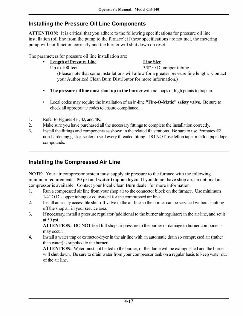
Operator's Manual: Model CB-140
4-17
Installing the Pressure Oil Line Components
Installing the Compressed Air Line
NOTE: Your air compressor system must supply air pressure to the furnace with the following minimum requirements: 50 psi and water trap or dryer. If you do not have shop air, an optional air compressor is available. Contact your local Clean Burn dealer for more information.1. Run a compressed air line from your shop air to the connector block on the furnace. Use minimum
1/4" O.D. copper tubing or equivalent for the compressed air line.2. Install an easily accessible shut-off valve in the air line so the burner can be serviced without shutting
off the shop air in your service area.3. If necessary, install a pressure regulator (additional to the burner air regulator) in the air line, and set it
at 50 psi. ATTENTION: DO NOT feed full shop air pressure to the burner or damage to burner components may occur.
4. Install a water trap or extractor/dryer in the air line with an automatic drain so compressed air (rather than water) is supplied to the burner. ATTENTION: Water must not be fed to the burner, or the flame will be extinguished and the burner will shut down. Be sure to drain water from your compressor tank on a regular basis to keep water out of the air line.
ATTENTION: It is critical that you adhere to the following specifications for pressure oil line installation (oil line from the pump to the furnace); if these specifications are not met, the metering pump will not function correctly and the burner will shut down on reset.
The parameters for pressure oil line installation are:• Length of Pressure Line Line Size
Up to 100 feet 3/8" O.D. copper tubing(Please note that some installations will allow for a greater pressure line length. Contact your Authorized Clean Burn Distributor for more information.)
• The pressure oil line must slant up to the burner with no loops or high points to trap air.
• Local codes may require the installation of an in-line "Fire-O-Matic" safety valve. Be sure to check all appropriate codes to ensure compliance.
1. Refer to Figures 4H, 4J, and 4K.2. Make sure you have purchased all the necessary fittings to complete the installation correctly.3. Install the fittings and components as shown in the related illustrations. Be sure to use Permatex #2
non-hardening gasket sealer to seal every threaded fitting. DO NOT use teflon tape or teflon pipe dope compounds.

Operator's Manual: Model CB-140
4-18
Installing the Stack
WARNING: Inappropriate stack materials or improper stack design/installation can adversely affect the proper, safe operation of your furnace. Contact your Clean Burn dealer to purchase the proper stack components for your furnace.
Stack designs are generally classified as follows:(1) "Class A" stack through the ceiling of the building (refer to Figure 4L)(2) "Class A" stack through the sidewall and up the side of the building (refer to Figure 4M)
Stack Design and Specifications
ATTENTION: The stack design must be single and dedicated for each unit (furnace) according to the following specifications. A single stack serving more than one unit MUST be engineered/certified for that specific installation (ref. NFPA 211, 3.3.39 and 10.2.1; NFPA 31 6.5.16-18). Failure to adhere to this rule may result in less than optimal system performance.
Figures 4L and 4M illustrate recommended stack designs. Choose the stack design which is appropriate for your furnace installation and review all specifications provided in the corresponding drawing. When designing your stack, adhere to the following specifications:
• Model CB-140 requires minimum 6" I.D. stack components.• Ensure that the vertical stack height is at least 10 feet PLUS one foot for every fitting (e.g. 45
degree, 90 degree, or T) in the stack run. If needed, increase the vertical length of the stack or install a draft inducer to obtain -.02" W.C. draft over fire. (Section 8 contains details on adjusting the draft.)
• Keep the horizontal stack run as short as possible; slant it upward at a minimum of 1/4" per foot of run.
• Keep the stack design simple. Complicated stacks (with long runs and many turns) reduce draft and result in poor burner performance. Your stack may include only one 90 degree turn. All other stack turns must be at 45 degrees or less to ensure optimal draft and burner performance
NOTE: If you plan to use an existing masonry chimney, the chimney must be lined and inside the building. Exterior masonry chimneys chill the stack gases and result in poor draft and poor burner performance.
ATTENTION: If you have an exhaust fan(s) in your shop, it is critical that you have adequate make up air (source of fresh air to replace the stale air exhausted by the fan). When an exhaust fan is run without adequate make up air, the resultant vacuum in the building will draw combustion products back into the burner. This back draft causes poor burner performance and may damage vital burner components. Refer to Section 8 in this manual for additional information.
Stack components should be installed in the following order: (1) Inside stack (the stack components from the furnace breach to within 18" of the ceiling, roof, or sidewall of your building) (2) Barometric damper (3) "Class A" stack penetration through the ceiling, roof, or sidewall (4) "Class A" stack on the exterior of the building (5) "Class A" stack cap

Operator's Manual: Model CB-140
4-19
Installing the Stack (continued)
Figure 4L - Installation of "Class A" Stack Through Roof/Ceiling
BEING SUCKED OUT OF THE
THE FAN TO PREVENTEXHAUST GASES FROM
IT IS FACING AWAY FROMMUST BE INSTALLED SOBAROMETRIC DAMPER
INSTALLING "CLASS A" STACK"CLASS A" KIT FOR
THROUGH CEILING
ATTENTION:
SEE SECTION 8
CLEAN OUT CAP
FURNACE OPERATION.
-.02" W.C. DRAFT OVER FIRE IS ESSENTIAL FOR PROPER
MIN. 6"STACK SIZE:
I89096-A
SIN
GLE
WA
LL S
TACK
MIN
. 24
GAU
GE
ROOF FLASHINGWATERTIGHT
"CLASS A" STACK CAP - NON-RESTRICTIVE TYPE TO ALLOW FREE FLOW OF THE STACK GASES
"CLA
SS A
" STA
CK C
OM
PON
ENTS
INSU
LLAT
ED S
TACK
WIT
H A
STA
INLE
SS S
TEEL
LIN
ER
3m (1
0') M
IN. V
ERTI
CAL
STAC
K H
EIG
HT
PLU
S 30
cm
(1')
FOR
EVER
Y FI
TTIN
G T
O M
AIN
TAIN
PRO
PER
DRA
FT O
VER
FIRE
10'
3'
SETTING DRAFT.ADJUST BAROMETRICDAMPER FOR -.02" W.C.DRAFT OVER FIRE
1/4" HOLE FOR
WARNING! MAKE SURE TO INSTALLTHE PROPER ROOF SUPPORTSYSTEM TO SAFELY SUPPORT THESTACK
DAMPER OPENING
WARNING! ENSURE PROPER CLEARANCES BETWEEN STACK COMPONENTS AND COMBUSTIBLES PER ALL APPLICABLE CODES.
NOTE: THE LAST STACK SECTION SHALL EXTEND AT LEAST 3' HIGHER THAN ANY RIDGE, PARAPET, WALL ORROOF STRUCTURE WITHIN 10' OF IT.
AIR OIL
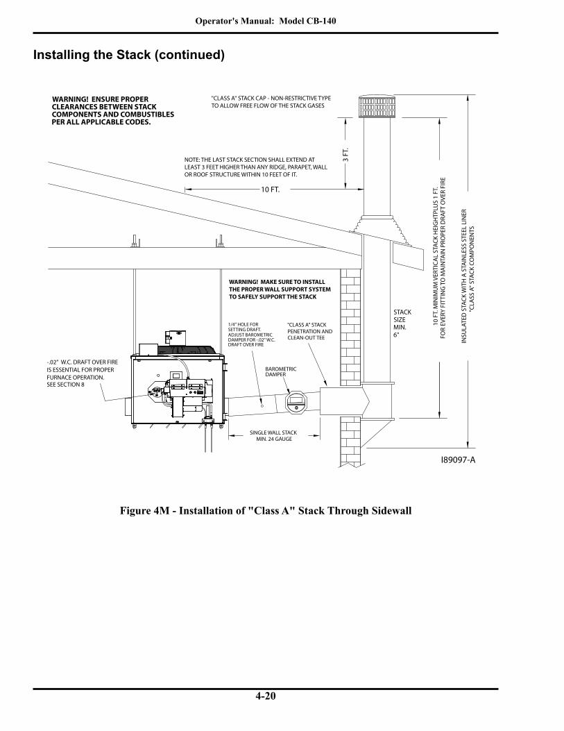
Operator's Manual: Model CB-140
4-20
Figure 4M - Installation of "Class A" Stack Through Sidewall
Installing the Stack (continued)
I89097-A
10 F
T. M
INIM
UM
VER
TICA
L ST
ACK
HEI
GH
TPLU
S 1
FT.
FOR
EVER
Y FI
TTIN
G T
O M
AIN
TAIN
PRO
PER
DRA
FT O
VER
FIRE
10 FT.
"CLASS A" STACK CAP - NON-RESTRICTIVE TYPETO ALLOW FREE FLOW OF THE STACK GASES
FURNACE OPERATION.IS ESSENTIAL FOR PROPER
DAMPER
-.02" W.C. DRAFT OVER FIRE
SEE SECTION 8
"CLA
SS A
" STA
CK C
OM
PON
ENTS
INSU
LATE
D S
TACK
WIT
H A
STA
INLE
SS S
TEEL
LIN
ER
"CLASS A" STACKPENETRATION AND CLEAN-OUT TEE
SINGLE WALL STACKMIN. 24 GAUGE
3 FT
.
SE SL
EROM
DRAFT
DRAFT OVER FIRE
SETTING DRAFT.ADJUST BAROMETRIC
1/4" HOLE FOR
DAMPER FOR -.02" W.C.
BAROMETRIC
WARNING! ENSURE PROPER CLEARANCES BETWEEN STACK COMPONENTS AND COMBUSTIBLES PER ALL APPLICABLE CODES.
STACK SIZE MIN. 6"
WARNING! MAKE SURE TO INSTALLTHE PROPER WALL SUPPORT SYSTEMTO SAFELY SUPPORT THE STACK
NOTE: THE LAST STACK SECTION SHALL EXTEND AT LEAST 3 FEET HIGHER THAN ANY RIDGE, PARAPET, WALLOR ROOF STRUCTURE WITHIN 10 FEET OF IT.
AIR OIL

Operator's Manual: Model CB-140
4-21
Installing the Interior Stack
WARNING: Single wall stack components may be used only for those portions of the stack which are located inside your building and away from any fire/burn hazards.
1. Install the single wall stack with proper clearances from combustibles. Also ensure that the stack is located a safe distance from all shop personnel.
2. Install an elbow at the junction of the horizontal and vertical stack components to allow for easy cleaning of the stack. ATTENTION: Avoid additional 90-degree turns in the stack. Each additional 90-degree turn slows down stack gases, creates back-pressure, and results in repeated burner shutdown and unnecessary service calls. All other turns in the stack should be at a 45-degree (or smaller) angle. NOTE: IMPORTANT for Canadian Installations - Local codes may require the installation of a clean-out tee.
Installing the Barometric Damper
1. Refer to Figure 4L. Install a single wall tee (min. 24 gauge) after the 90 degree elbow in the straight vertical stack section within three to five feet of the furnace breach. For horizontal stack runs (as shown in Figure 4M), install the tee after the first straight section of pipe. NOTE: The tee is required to support the barometric damper. You must purchase this tee when you purchase your stack materials (6" single wall tee - CB #70301).
2. Refer to Figure 4N. Install the barometric damper in the opening of the tee. Use a small spirit level to make sure that it is properly level.
3. Install two self-tapping screws as shown in Figure 4N (i.e. one on each side of the barometric damper) to hold the damper in place. DO NOT install a screw at the bottom of the barometric damper, or the flapper of the damper will not operate correctly.
NOTE: Specifications for adjusting the barometric damper for proper draft over fire are provided in Section 8 of this manual.
C770076" CLEAN BURN BAROMETRIC DAMPERINSTALLED IN SINGLE WALL TEE ADJUST THIS WEIGHT TO
OBTAIN PROPER DRAFT
1
No QTY PART # DESCRIPTION
6" BAROMETRIC DAMPER3115311
Figure 4N - Installation of Barometric Damper

Operator's Manual: Model CB-140
4-22
Installing the Stack Safety Switch For Canadian Installations
NOTE: CSA Standards require that all heating equipment must be installed with a stack safety switch. If your heating equipment is being installed in Canada, follow the instructions listed below.
CAUTION: For your safety and the safe operation of your heating equipment, the stack switch must be installed by a qualified installer in accordance with the installation instructions provided here. Wiring
must be accomplished in accordance with all applicable codes. Failure to adhere to these safety recommendations may result in serious personal injury and/or equipment damage.
1. Follow the instructions in the Operator’s Manual, Section 4 to install a proper stack, including the barometric damper which must be installed within 40 inches of the breach. NOTE: The barometric damper must be installed so that it is level and the flapper moves freely.
2. Ensure that main power to the heating equipment is turned OFF.3. Position the stack safety switch over the lip of the barometric damper as shown in Figure 4O.4. Drill a 1/8” pilot hole for the mounting screw, and mount the stack safety switch using the mounting
screw supplied with the switch. NOTE: The mounting screw must not interfere with the free movement of the flapper on the barometric damper.
5. Install the wall thermostat according to the instructions provided in the Operator’s Manual, Section 4. Wire the wall thermostat and stack safety switch in series as shown in Figure 4P. Install the wire so that it is secured away from any hot surfaces.
6. When the heating equipment installation is completed, follow the instructions in the Operator’s Manual, Sections 5 and 6 to prime the pump and start/adjust the burner.
7. Follow instructions in the Operator’s Manual, Section 8 to check the draft; this is crucial for the proper, safe operation of the heating equipment.
Figure 4O - Stack Safety Switch Installed on the Barometric Damper
I88964

Operator's Manual: Model CB-140
4-23
Resetting the Stack Safety Switch
WARNING: BURN HAZARD! To prevent serious personal injury, be sure to allow ample time, at least 30 minutes, for the stack, barometric damper, and switch to cool down before attempting to access and
service these components. It is crucial to identify the cause of the stack obstruction (e.g. heavy snowfall) and correct it before resetting the stack safety switch and re-starting the burner. DO NOT operate the heating equip-ment with an obstructed stack; failure to correct an obstructed stack may result in fire, explosion, and/or burn hazards causing serious personal injury or death.
NOTE: In locations where heavy snowfall occurs, it is critical that the stack remain unobstructed by snow. For safe heating equipment operation, be sure to keep the area surrounding the stack clear of snow.
1. Before resetting the stack safety switch, check the stack to make sure it is clear of any obstructions.2. Remove the cover from the stack safety switch, and push the small button in the middle of the switch.3. Pushing the stack safety switch reset button will re-establish the thermostat circuit, and the burner will
start (assuming the wall thermostat is calling for heat).
Understanding the Function of the Stack Safety Switch
The Stack Safety Switch monitors the temperature at the barometric damper on the stack and is designed to de-tect the obstruction of the free flow of stack gases from the heating equipment and shut down the burner. Obstruc-tion of the stack results in the “spillage” of stack gases from the barometric damper, which heats up the switch. The switch then opens, disconnecting the thermostat circuit to the burner, and the burner shuts off.
Figure 4P - Stack Safety Switch Wiring Diagram
Stack Safety Switch Specifications
Switching Voltage 24 voltsSwitch OPEN Temperature 180 degrees FSwitch Type L180, normally closed, manual reset
TT
FF
I88965
WALLTHERMOSTAT
OILPRIMARY
STACKSAFETYSWITCH(MOUNTED ON
BAROMETRIC DAMPER)

Operator's Manual: Model CB-140
4-24
Installing the Optional Draft Inducer
ATTENTION: The draft inducer, Field brand model DI-2, is optional equipment and may be installed to ensure proper draft. The Field brand draft inducer has been tested for use on Clean Burn furnaces. DO NOT use other models or brands of draft inducers.
Understanding the Importance of the Draft InducerThe draft inducer is designed to aid in the removal of the natural draft created by the appliance to vent the com-bustion gases to the outside of the building. As the paddle wheel turns, a negative pressure is maintained within the stack so that the combustion gases can leave the furnace and travel out of the stack. (See Figure 4Q.) Proper sizing, installation, and adjustment of the draft inducer are critical for optimal draft inducer operation.
Installing the Exterior Stack
ATTENTION: All exterior stack pieces must be Class A/UL103 HT double-wall insulated all-fuel stack compo-nents with a stainless steel liner.
• DO NOT use Class B or BW Vent/double-wall stack components (for gas fired appliances only). • DO NOT use Type L Vent/double-wall stack components (for approved fuel oil appliances only).• DO NOT use black stack pipe (for solid fuel burning appliances only).• DO NOT use single-wall stack for your exterior stack. Single-wall exterior stack chills the stack
gases and results in poor draft and poor burner performance.
1. Refer to Figure 4L / 4M as needed.2. Follow the installation instructions provided by the stack manufacturer.3. Install water-tight roof flashing around the penetration of the exterior stack.
NOTE: Clean Burn recommends the use of "Dektite" roof flashing (or equivalent) which ensures a water-tight seal when installed properly. Contact your local Clean Burn dealer for details.
Installing the Stack Cap
NOTE: Proper installation of a "Class A" stack cap ensures the free flow of stack gases which is essential for optimal burner performance.
1. Refer to Figure 4L / 4M as needed. Your stack cap should be classified as: "Class A" non-restrictive, all-fuel type.
2. Install the stack cap according to the manufacturer's instructions.
Installing the Stack Penetration
WARNING: When running the stack through your ceiling, roof, or sidewall, you must use Class A/UL 103 HT double-wall insulated all-fuel stack components with a stainless steel liner. DO NOT run sin-
gle-wall stack through your ceiling, roof or sidewall. NEVER locate a stack joint inside walls or in a joist spacer. Ensure proper clearances from combustibles per all applicable codes.
1. Refer to Figure 4L / 4M as needed.2. Follow the installation instructions provided by the stack manufacturer.

Operator's Manual: Model CB-140
4-25
Figure 4Q - Installation of the Optional Draft Inducer
WARNING: Turn OFF the main power to the furnace before proceeding with the installation of the draft inducer.
ATTENTION: It is very important to install the draft inducer on a vertical section of stack to isolate the inducer from excessive heat and ash buildup. Never install the draft inducer on a horizontal section of stack close to the furnace breach where heat and ash will damage the inducer motor.
Installing the Optional Draft Inducer (continued)
NOTE: Lubricate the motor as recommended by theDraft Inducer manufacturer.
I89098-A
CLEAN-OUT CAPINSTALLED ON L.H.FURNACE BREECH
5 FE
ET -
8 FE
ET
CHECK FOR-.02" W.C. DRAFT OVER FIRE
DRAFTOPTIONAL
ADJUSTMENT PLATE
DRAFT SIN
GLE
WA
LL24
GA
. IN
TERI
OR
STAC
K
SERVICEMAN ADJUSTSBAROMETRIC DAMPER TOOBTAIN -.02" W. C. DRAFTOVER FIRE
"CLASS A" STACK
INDUCER
NOTE: INSTALL THE DRAFT INDUCER INTHE LAST SECTION OF VERTICAL STACKTO POSITION THE DRAFT INDUCER AWAYFROM THE FURNACE BREECH SO THEMOTOR DOES NOT OVERHEAT. THIS ALSOREDUCES ASH ACCUMULATION IN THEDRAFT INDUCER.
DO NOT MOUNT THE DRAFT INDUCER INTHE HORIZONTALSTACK NEAR THEFURNACE BREECH.
AIR OIL

Operator's Manual: Model CB-140
4-26
Inspecting the Furnace Installation
Following completion of all installation activities described in this chapter, the furnace should be inspected by qualified personnel before firing. This ensures that your installation meets all applicable national and local codes and allows for any deficiencies to be corrected before furnace startup. Improper installation may void your warranty.
Installing the Wall Thermostat
1. Select a location for the thermostat on an interior wall away from any hot or cold drafts.2. Remove the top cover from the thermostat by pushing gently on the latch at the top center of the body.
(Hold the thermostat base in one hand, and grasp the body with the other hand; push in on the latch with your thumb, and pull the cover away from the base.) ATTENTION: DO NOT use a screwdriver to pry the cover off the base, or damage may occur.
3. Remove the green paper insert and the black plastic battery isolator from the battery section of the thermostat.
4. Refer to the Burner Wiring Diagram in Appendix B at the back of this manual. Run two wire, 18-gauge (minimum) thermostat cable from the terminals on the back of the thermostat base to the T/T terminals of the primary control on the burner. ATTENTION: NEVER jump between T/T terminals on the primary control without removing one of the wires. Failure to remove one of the wires will burn out the heat anticipator on the thermostat and will cause the thermostat to fail.
5. Mount the thermostat base 60" to 66" from the floor using the hardware provided.6. Reassemble the thermostat body onto the base. (Align the hinges at the bottom of the cover with
the slots at the bottom of the base, and swing the cover up into place.)
Replacing the Wall Thermostat Batteries
1. Proper battery level is indicated by the room temperature being displayed on the LCD screen.2. When the battery level becomes low, a battery icon along with the word "REPLACE" will be displayed in
the lower left corner of the LCD screen. Replace the batteries to ensure proper operation, following the previous instructions on the thermostat disassembly procedure.
3. If the batteries are not replaced, the display will slowly become dim and not display any information. The thermostat will eventually not function. If this happens, replace the batteries immediately.
1. Refer to Figure 4Q. Follow the instructions included with the draft inducer to mount the draft inducer on the section of single-wall vertical stack.
2. Position the draft plate all the way out so that it does not reduce the draft produced by the draft inducer Follow instructions in Section 8 (Adjusting the Draft Over Fire) to set the proper draft.
Wiring the Draft Inducer for Normal Operation* *(No exhaust fans in the building. Read pages 8-3 to 8-6 if exhaust fans are present.)1. Wire the draft inducer according to the Furnace Wiring Diagram provided in Appendix B at the
back of this manual.
Installing the Optional Draft Inducer (continued)
Operator's Manual: Model CB-140
5-1
SECTION 5: METERING PUMP PRIMING
Understanding Metering Pump Priming
Preparing your Clean Burn furnace for operation begins with priming the metering pump. The procedures in this section must be performed in sequence without interruption to properly prime the pump.
Required Tools and MaterialsThe following tools and materials are required for oil pump priming and should be gathered before starting any procedures:
• 3/8" open-end wrench• 5/8" open-end wrench• Rags• Two containers (minimum one-gallon)• Permatex #2 non-hardening gasket sealer• Adjustable Wrench• Pipe Wrench

Operator's Manual: Model CB-140
5-2
Priming the Metering PumpATTENTION: The priming process must be done precisely as described in this procedure to ensure that all air is thoroughly bled from the system. Failure to bleed all air from the system will result in repeated burner shutdowns on reset.
1. Refer to Figure 5A.2. Remove the 1/4" NPT plug from the side of the pump head, and set it aside.3. Remove the 1/2" brass cap from the 1/2" brass nipple. Place a funnel in the opening. Slowly pour used
oil into the funnel until oil comes out of the side of the pump head; this will fill the oil line, canister filter, and pump head with oil. ATTENTION: NEVER run the pump head dry (i.e. without oil in the pump head); doing so will severely damage the pump.
4. Apply Permatex #2 non-hardening gasket sealer to the threads of the plug (removed from the pump head). Re-install the plug and tighten.
5. Apply Permatex #2 non-hardening gasket sealer to the threads of the 1/2" brass nipple. Re-install the 1/2" brass cap on the brass nipple and tighten.
6. Open the bleeder valve on the pump two to three (2-3) full turns, and position a container to catch oil which will flow from the bleeder during pump priming.
7. Close the mini ball valve at the outlet port of the pump head. ATTENTION: Verify that the relief oil line is installed back to the tank before closing the mini ball valve. Closing the mini ball valve will cause the internal pump relief valve to open.
Figure 5A - Priming the Metering PumpI88756-C
SUCTION LINE
RETURN TO TANK
TO TANK
CANISTERFILTER
VACUUM GAUGE
PUMP
TO BURNER
GEARMOTOR
1/2" BRASS
1/2" BRASS
BLEEDER VALVE
NIPPLE
CAP
1/4" PLUG
MINI BALLVALVE
BALL VALVE

Operator's Manual: Model CB-140
5-3
8. Activating the Pump NOTE: The CB-140 furnace features a priming switch which is mounted on the right-hand side of the electrical junction box on the front of the furnace cabinet. The priming switch has two positions:• PRIME (switch is in the UP position): This is used only for pump priming. When the switch is in
the UP position, the pump circuit is activated for priming. The pump will continue to run as long as the switch is in this position. The oil primary control circuit is de-activated so the burner cannot run while the switch is in the UP position.
• BURNER (switch is in the DOWN position): This is used for normal burner operation. When the switch is in the DOWN position, the burner controls the operation of the pump. The pump will only run while the burner is running.
a. Refer to Figure 5B to locate the priming switch.b. Turn the priming switch to the prime (UP) position. The pump should immediately start running.
Priming the Metering Pump (continued)
Figure 5B - Locating the Pump Priming Switch
I89099-A
OIL PUMPPRIMINGSWITCH

Operator's Manual: Model CB-140
5-4
Priming the Metering Pump (continued)
Vacuum Testing the Oil Pump
Vacuum testing the oil pump is a very accurate way to determine the following:• The condition of the pump -- the ability of the pump to pull a vacuum and suck oil from the tank.• The condition of the fittings, gaskets and seals from the ball valve to the pump -- these components
must all be airtight to avoid suction leaks.The following procedure provides instructions for vacuum testing the pump and canister filter on systems equipped with a ball valve.
ATTENTION: For the pump to pull and hold vacuum, it is critical that all fittings are airtight. If any of these fit-tings are loose, the pump may not pull a vacuum or may lose the vacuum rapidly. It is also critical that all fittings in the suction line, including fittings on the canister filter, are 100% airtight.
1. Follow the instructions to prime the pump (previous procedure). NOTE: The pump will not pull a vacuum if the pump is dry. There must be oil in the gears of the pump before the pump can pull a vacuum.
2. With the pump running, open the bleeder two to three full turns, and make sure that oil is flowing from the bleeder. DO NOT close the bleeder yet.
3. Refer to Figure 5A. Close the ball valve at the inlet to the canister filter. Observe the vacuum gauge. NOTE: The ball valve must have a stainless steel ball and should be pressure tested by the manufacturer to ensure that it does not leak. If the ball valve leaks, the vacuum test will not be accurate.
4. The vacuum should increase within 30 seconds to 15 inches of vacuum. When the vacuum gauge reads 15 inches of vacuum, first close and tighten the bleeder, then turn the pump off and close the mini ball valve at the outlet port of the pump. Observe the vacuum gauge. NOTE: If the pump will not pull at least 15 inches of vacuum, there is a very serious suction leak, or the pump is damaged
9. Run the pump until a solid stream of oil flows from the pump bleeder. This will bleed all air out of the suction line, oil filter and pump head. ATTENTION: For the metering pump to operate correctly, it is very important that the system is entirely full of oil and all air is bled out. The burner will shut down if there is any air in the system
10. Open the mini ball valve at the outlet port of the pump head to allow the pressure oil line to be filled11. Close and tighten the bleeder on the pump.12. Turn the priming switch to the burner (DOWN) position so that the pump stops running.13. Disconnect the pressure oil line from the burner and position a container to catch oil which will flow
from the pressure oil line during pump priming.14. Turn the priming switch to the prime (UP) position. The pump should start running immediately .15. Run the oil pump until the proper flow of oil has been established, and the oil line has been completely
flushed out.16. Turn the priming switch to the burner (DOWN) position so that the pump stops running.17. Re-connect the oil line to the burner.

Operator's Manual: Model CB-140
5-5
Vacuum Testing the Oil Pump (continued)
5. If there are no suction leaks, the system will hold vacuum. NOTE: It is acceptable for the vacuum to drop one to five inches within one minute as the seal in the pump seats. The vacuum should then hold steady for 15 minutes.
ATTENTION: If the vacuum drops more than one to five inches within the first minute, there is one or more leaks somewhere between the pump and the ball valve. Do the following:
• Wipe your finger along the cylinder at the shaft of the pump. If there is oil here, the pump seal is damaged. Replace the pump.
• Disassemble and clean all the fittings from the pump to the ball valve. Properly seal all fittings with Permatex #2 non-hardening gasket sealer or equivalent. Check the condition of the o-ring on the canister filter and tighten the four canister filter bolts in a crisscross pattern.
• Repeat the procedure to vacuum test the system to ensure that the system is air tight.
6. Follow the instructions to prime the metering pump after a vacuum test has been performed.

Operator's Manual: Model CB-140
5-6
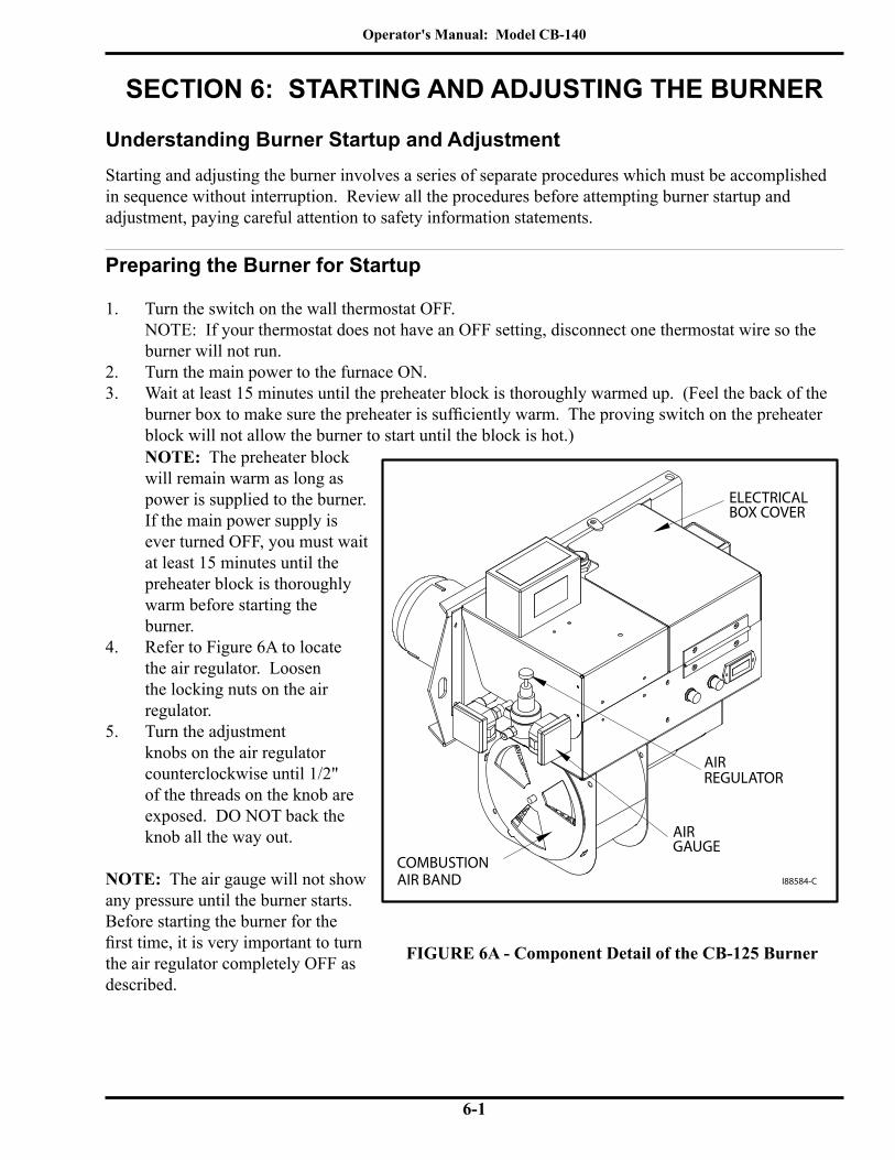
Operator's Manual: Model CB-140
6-1
SECTION 6: STARTING AND ADJUSTING THE BURNER
Understanding Burner Startup and AdjustmentStarting and adjusting the burner involves a series of separate procedures which must be accomplished in sequence without interruption. Review all the procedures before attempting burner startup and adjustment, paying careful attention to safety information statements.
Preparing the Burner for Startup
1. Turn the switch on the wall thermostat OFF. NOTE: If your thermostat does not have an OFF setting, disconnect one thermostat wire so the burner will not run.
2. Turn the main power to the furnace ON.3. Wait at least 15 minutes until the preheater block is thoroughly warmed up. (Feel the back of the
burner box to make sure the preheater is sufficiently warm. The proving switch on the preheater block will not allow the burner to start until the block is hot.)
FIGURE 6A - Component Detail of the CB-125 Burner
NOTE: The preheater block will remain warm as long as power is supplied to the burner. If the main power supply is ever turned OFF, you must wait at least 15 minutes until the preheater block is thoroughly warm before starting the burner.
4. Refer to Figure 6A to locate the air regulator. Loosen the locking nuts on the air regulator.
5. Turn the adjustment knobs on the air regulator counterclockwise until 1/2" of the threads on the knob are exposed. DO NOT back the knob all the way out.
NOTE: The air gauge will not show any pressure until the burner starts. Before starting the burner for the first time, it is very important to turn the air regulator completely OFF as described.
I88584-C
COMBUSTIONAIR BAND
REGULATORAIR
ELECTRICALBOX COVER
GAUGEAIR

Operator's Manual: Model CB-140
6-2
Oil Type Oil PSI / Flame Length Air PSI Air Band Nozzle #2 Fuel Oil check flame length 14-18 1/2" 9-5 #4 Fuel Oil check flame length 14-18 1/2" 9-5 Used Crankcase Oil check flame length 14-18 1/2" 9-5 Used ATF check flame length 14-18 1/2" 9-5 Used Hydraulic Oil check flame length 14-18 1/2" 9-5
Starting the Burner
1. Turn the switch on the wall thermostat to HEAT and adjust the thermostat setting above room temperature to start the burner.
2. Adjusting the Air Regulator: As soon as the burner starts running, turn the knob on the air regulator clockwise to achieve proper operating air pressure. Refer to the Initial Adjustment Charts. NOTE: If the safety reset on the primary control is activated and the burner stops running, see Section 7 for further instructions on restarting your burner.
3. Observing the Flame Length: Visually inspect the flame length through the observation port. Refer to Figure 6B for an illus-tration of the desired flame length. The flame should extend no more than one-half of the way down the combustion chamber. WARNING: The observation port gets hot as the burner fires. To avoid personal injury, always wear heavy work gloves and safety glasses when opening the port and viewing the flame.
Preparing the Burner for Startup (continued)
6. Initial Adjustment of the Combustion Air Band: WARNING: The combustion air band must be properly adjusted to ensure that the burner ignites and burns correctly. DO NOT attempt to start the burner with the combustion air band wide open or completely closed. The burner may not ignite correctly. Failure to heed this warning may result in a fire or explosion hazard.• Refer to Figure 6A to locate the combustion air band.• Rotate the combustion air band to adjust it to the appropriate initial slot opening as listed in the
following Initial Adjustment Charts. Use a ruler to accurately set the combustion air band gap. IMPORTANT NOTE: This initial setting of the combustion air band will allow you to start the burner. You will fine tune the combustion air band further as described later in these instructions.
ATTENTION: The settings shown in the charts below are only initial adjustments. Final adjustments must be done by inspecting the flame length according to the illustration provided on the following page.
NOTE: The oil pressure is automatically adjusted by the metering pump.
Initial Adjustments for the CB-140 Furnace Maximum Input = 140,000 BTUH @ 1.0 GPH with CB-125 Burner

Operator's Manual: Model CB-140
6-3
FIGURE 6B - Flame Length Adjustment
Correct Maximum Flame Adjustment(Proper Oil and Air Pressure with correct supply of Com-bustion Air):
• Flame goes half of the way down the combustion chamber
• Flame does not touch back or walls of combustion chamber.
Incorrect Flame Adjustment(Not Enough Combustion Air):
• Flame must not touch back or walls of combustion chamber
• Increase combustion air by opening the air band on the side of the burner.
Incorrect Flame Adjustment(Air Pressure Too High):
• Ensure proper air pressure setting.
Starting the Burner (continued)
NOTE: Increasing combustion air will shorten the flame; decreasing the combustion air will lengthen the flame.
4. Check the flame length after the burner has fired for 15 minutes.5. Tighten the locking nuts on the air regulator.6. Fine Tuning the Combustion Air Band:
NOTE: The initial setting of the combustion air band may require additional adjustment.• Refer to Figure 6A to identify the combustion air band location on the burner.• Observe the flame. The flame should be yellow-white with sharp tips and no "sparkles."• If the flame is orange in color or the flame length is too long, the oil you are burning
requires MORE combustion air. OPEN the air band 1/8" to 1/4", and re-check the flame for the proper characteristics.
• Re-check the flame after ten minutes. You should see a yellow-white flame with sharp tips and no "sparkles", and the flame should extend half of the way down the combustion chamber.
I89100
Operator's Manual: Model CB-140
6-4
Starting the Burner (continued)
7. Checking for a Smokeless Burn: Check for a smokeless burn by observing the stack while the burner is running. If you see any smoke, repeat the previous steps for setting the combustion air band and adjusting the air regulator. After adjusting the combustion air band, re-check the flame length. NOTE: Check for a smokeless burn periodically (as you do the flame length). Immediately readjust the burner if you ever see smoke coming from the stack. Smoke indicates improper combustion air adjustment. NOTE: When using instruments to adjust the burner for a smokeless burn, the following readings should be achieved:
• Draft over fire should be -.02 inch w.c.• Adjust for a smoke spot of a trace to 2• Adjust for a CO2 reading of 9% to 11% or an O2 reading of 7% to 8%• Cad cell reading below 500 ohms
Checking the Operation of the Fan Motor
NOTE: It is important to verify that the fan motor operates correctly to ensure that the fan switch is properly cycling the fan motor as described below. Also refer to Appendix A at the back of the manual for additional pertinent information.
1. Start the burner and adjust it as described previously in this section.2. The fan motor will not start until the burner has been running for 3 to 5 minutes to heat up the
combustion chamber and heat exchanger. At this point, the fan switch will activate the fan motor.
3. Once the fan motor has activated, turn the burner off by turning the wall thermostat to OFF.4. With the burner off, the fan motor should continue to run for 5 to 10 minutes until the
combustion chamber is cooled down. The fan switch will then shut off the motor.
WARNING: If the fan motor does not operate as described, immediately shut down your furnace to avoid potential equipment damage and/or fire hazard. Contact your Clean Burn dealer
immediately.
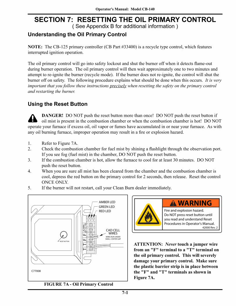
Operator's Manual: Model CB-140
7-1
SECTION 7: RESETTING THE OIL PRIMARY CONTROL
Understanding the Oil Primary Control
NOTE: The CB-125 primary controller (CB Part #33400) is a recycle type control, which features interrupted ignition operation.
The oil primary control will go into safety lockout and shut the burner off when it detects flame-out during burner operation. The oil primary control will then wait approximately one to two minutes and attempt to re-ignite the burner (recycle mode). If the burner does not re-ignite, the control will shut the burner off on safety. The following procedure explains what should be done when this occurs. It is very important that you follow these instructions precisely when resetting the safety on the primary control and restarting the burner.
Using the Reset Button
DANGER! DO NOT push the reset button more than once! DO NOT push the reset button if oil mist is present in the combustion chamber or when the combustion chamber is hot! DO NOT operate your furnace if excess oil, oil vapor or fumes have accumulated in or near your furnace. As with any oil burning furnace, improper operation may result in a fire or explosion hazard.
1. Refer to Figure 7A.2. Check the combustion chamber for fuel mist by shining a flashlight through the observation port.
If you see fog (fuel mist) in the chamber, DO NOT push the reset button.3. If the combustion chamber is hot, allow the furnace to cool for at least 30 minutes. DO NOT
push the reset button.4. When you are sure all mist has been cleared from the chamber and the combustion chamber is
cool, depress the red button on the primary control for 2 seconds, then release. Reset the control ONCE ONLY.
5. If the burner will not restart, call your Clean Burn dealer immediately.
FIGURE 7A - Oil Primary Control
ATTENTION: Never touch a jumper wire from an "F" terminal to a "T" terminal on the oil primary control. This will severely damage your primary control. Make sure the plastic barrier strip is in place between the "F" and "T" terminals as shown in Figure 7A.
Fire and explosion hazard.Do NOT press reset button untilyou read and understand ResetProcedures in Operator's Manual.
42000 Rev. 2
WARNING
FF
TT
CAD CELLWIRES
RESET BUTTON
C77008
GRNAMB RED
ALA
RM
AMBER LEDGREEN LEDRED LED
WIRES RUN UNDERSMALL CENTER GAP
( See Appendix B for additional information )

Operator's Manual: Model CB-140
7-2
The Blower/Fan SwitchThe CB-140 furnace features an F-180 blower/fan switch (normally open) which is surface mounted at the front of the combustion chamber (see Figure 7B). The blower/fan switch senses the temperature of the combustion chamber as the burner is firing. When the combustion chamber reaches the proper temperature, the blower/fan switch closes and sends power to the fan motor to turn ON the fan. When the wall thermostat is satisfied and the burner shuts off, the fan continues to run until the switch senses that the combustion chamber has cooled down. The switch then opens and shuts off the fan motor.
The Hi-Temp Limit SwitchesThese furnaces also feature two high temperature limit switches which are mounted on a bracket at the front of the combustion chamber as shown in Figure 7B. The switches sense the build-up of heat within the combustion chamber and are designed to protect the furnace from damage due to overheating. The limit switches are wired in series, and both are auto-resetting.
Understanding the Function of the L-200 Hi-Temp Limit SwitchIf the temperature of the combustion chamber is too hot, the L-200 hi-temp limit switch opens and shuts off power to the primary control on the burner, and the burner shuts off. The fan continues to run to cool down the furnace. After the combustion chamber has cooled down, the L-200 hi-temp limit switch will automatically reset and allow the burner to restart.ATTENTION: If the L-200 hi-temp limit switch is opening repeatedly, the burner MUST be readjusted according to the instructions in Section 6 to correct the overheating problem, or serious damage to the furnace may occur.
The L-200 hi-temp limit switch will open and shut down the burner if any of the following conditions exists:
• The furnace is over firing. Review the directions in Section 6 to properly adjust the burner• Ductwork is installed on the furnace. The CB-140 furnace is not designed for ductwork
applications.
Understanding the Function of the L-290 Auxiliary Auto-Reset Hi-Temp Limit SwitchThe L-290 auxiliary auto-reset high temperature limit switch is a back-up safety switch for the L-200 hi-temp limit switch.
Both the L-200 and L-290 auxiliary hi-temp limit switches will open and shut down the burner if:
• The fan has stopped running for any reason during furnace operation, the heat in the furnace will cause the limit switches to open. Ensure that the fan is functioning properly.
ATTENTION: It is very important to determine the reason for the opening of the limit switches and take steps to correct the cause; failure to do so may result in serious overheating and damage to the heat exchanger of the furnace. Additionally, if the burner is rapidly cycling on/off, contact your Clean Burn Distributor immediately; failure to address this situation may result in serious damage to the furnace.

Operator's Manual: Model CB-140
7-3
I89101-A
SURFACE MOUNT
BLACK AND TAN WIRE
RED & TAN WIRETO BURNER
SWITCHES IN SERIESRED & TAN WIRE LINKS THE 2
(33390) L-200 HI LIMIT NC
BLOCKFROM TERMINAL RED & TAN WIRE
TO TERMINAL BLOCK
(33230) F-180
FAN SWITCH
SWITCH (AUTO RESET)33288 L-290 HI LIMIT AUXILIARY
BREECH
CLEAN-OUT CAP
CLEAN-OUT
AUTO RESET
The Hi-Temp Limit Switches (continued)
Figure 7B - Locating the Hi-Temp Limit Switches

Operator's Manual: Model CB-140
7-4

Operator's Manual: Model CB-140
8-1
SECTION 8: ADJUSTING THE DRAFT OVER FIRE
Checking for Correct Draft Over Fire
WARNING: Correct draft over fire is essential for the proper and safe operation of
your furnace.
Your furnace is equipped with an observation/draft reading port to check draft over fire. Qualifiedservice personel with proper equipment must check/adjust your furnace for proper draft. Contact your Clean Burn dealer for this service.
1. Insert the probe of the draft gauge instrument into the draft reading port in the observation port as shown in Figure 8A. NOTE: Follow the directions with the draft gauge to use your specific type of gauge.
2. Note the draft over fire reading on the draft gauge. ATTENTION: The draft reading should be in the -.02 to -.04 w.c. range. Poor draft (i.e. -.01 to +.08) results in back pressure in the furnace and poor burner performance. Too much draft over fire (i.e. greater than -.04) sucks the heat from the furnace and results in abnormally high stack temperature. Figure 8A - Checking for Proper
Draft Over Fire
Understanding the Importance of Draft
Draft in the furnace is created as the hot combustion gases rise up the stack, creating a negative pressure inside the stack and the furnace. This negative pressure is measured as inches of water column (W.C.) of draft. A proper draft over fire of -.02 to -.04 w.c. is essential so that all combustion products travel away from the burner, down the combustion chamber, through the furnace flue tubes and up the stack.
I88257

Operator's Manual: Model CB-140
8-2
Adjusting the Barometric Damper
NOTE: If the draft over fire is not in the -.02 to -.04 w.c. range, it is necessary to adjust the barometric damper.
Figure 8B - Adjustment of Barometric Damper
1. Before starting the burner, turn the weight on the flapper COUNTERCLOCKWISE until the flapper remains closed. This will provide maximum draft for the furnace.
2. Follow the directions in Section 6 to start and adjust the burner.
3. With the burner running, check the draft over fire with a draft gauge.
4. As shown in Figure 8B, adjust the weight on the flapper to obtain a consistent -.02 w.c. draft over fire. Turn the weight COUNTERCLOCKWISE to increase draft (i.e. draft increases as the flapper closes). Turn the weight CLOCKWISE to decrease draft (i.e. draft decreases as the flapper opens).
5. Tighten the locking nut to securely hold the weight in position.
Solving Draft Over Fire Problems
WARNING! If you cannot achieve proper draft over fire, do not operate your furnace! Contact your Clean Burn dealer for assistance.
ATTENTION: Backdraft must be resolved or your furnace will not operate correctly!Under backdraft conditions, draft over fire readings will show positive pressure in the combustion chamber. Backdraft means that oil spray, combustion products, and heat are blown back against the burner. Backdraft results in oil-fouled retention heads and electrodes. Severe backdraft will force heat back against the burner and result in heat damage to the cad cell and transformer.
• Backdraft is caused by the following conditions:• Poor draft caused by improper stack design. (See Section 4.)• Poor draft caused by improper adjustment of the barometric damper. (See Above)• Incorrect combustion air band setting on the burner. (See Section 6.)• Furnace flues are plugged with ash. (See Section 9.)• Exhaust fans in your building are sucking gases down the stack. (See following pages)
TO OBTAIN PROPERADJUST THIS WEIGHT TO OBTAIN PROPERDRAFT OVERFIRE
I88572

Operator's Manual: Model CB-140
8-3
Understanding the Effect of Exhaust Fans on Draft
Any type of exhaust fan, paint booth, or exhaust system in a building will create negative pressure in the building unless there is a source of make-up air (i.e. fresh air which enters the building and replaces the air removed by the exhaust fans.) Refer to Figure 8C on the following page.
If there is insufficient make-up air, the exhaust fan will suck air and combustion gases down the furnace stack and create backdraft in the furnace. Even if the exhaust fan is on another level of the building or in another room away from the furnace, the exhaust fan will still create backdraft at the furnace.
Checking Draft Over Fire to Determine Severity of Backdraft
The following procedure is an accurate method of determining how much backdraft is created by the exhaust fans. Once this is determined, you can select the correct method for resolving the backdraft. Refer to Figure 8C on the following page as needed.
1. Turn off ALL exhaust fans and close ALL doors and windows in the building (any open door or window will allow make-up air to enter the building and will negate the test).
2. Start the furnace and adjust the barometric damper so that the draft over fire is -.02 w.c.3. Check the draft over fire again. Now have someone start the exhaust fans.4. Note how much the draft over fire has changed.
ATTENTION: If the draft over fire changed towards positive, it is mandatory that make-up air is provided to the building or severe damage to the furnace and burner will occur (voiding the warranty). If the draft over fire remained constant at -.02 w.c., there is sufficient make-up air entering the building, and the exhaust fan is not adversely affecting the draft.

Operator's Manual: Model CB-140
8-4Figure 8C - Proper Draft vs. Backdraft
DRAFTMO
RE
LESS
COMBUSTION AIRTO BURNER
DRAFTMO
RE
LESS
I89103-A
SERVICE PERSONNELSPECIAL NOTE TO
BACKDRAFTCREATED BYEXHAUST FAN
BACKDRAFTEXHUST FAN CREATES BACKDRAFT IN STACKAND SUCKS COMBUSTION GASES DOWN THESTACK AND BACK INTO THE FURNACE
PROPER DRAFT
RISING HOTCOMBUSTIONGASES PRODUCEPROPER DRAFT
64.1626
TO ARRIVE AT PROPER DRAFT MEASUREMENTS BE SURE THAT ALL FANS WITHIN THE BUILDING ARE RUNNING WHILE ADJUSTING THE DRAFT TO FINAL LEVELS!
OIL SPRAY AND HEAT IS FORCED BACK AGAINST THE BURNER AND RESULTS IN OIL FOULED ELECTRODES AND RETENTION HEAD. SEVERE BACKDRAFT WILL HEAT AND DAMAGE THE CAD CELL AND THE TRANSFORMER.
DRAFT OVERFIRE OF -.02 TO -.04 W.C. MEANS COMBUSTION GASES ARE FLOWING AWAY FROM THE BURNER,THROUGH THE FURNACE FLUES AND UP THE STACK
SERVICEMAN ADJUST BAROMETRIC DAMPER TO OBTAIN -.04 TO -.06 W.C. DRAFT AT STACK
Corresponding Draft Over Fire measurement should be -.02 to -.04 WC
Operator's Manual: Model CB-140
8-5
Installing a Make-up Air Louver
Exhaust Fans and Make-up Air Louvers
When exhaust fans are operated in tight buildings, there is little or no source of fresh air to replace the air removed from the building by the exhaust fan. This results in negative pressure (vacuum) in the building which creates severe backdraft problems at the furnace.
Properly sized make-up air louvers are designed to allow adequate fresh air to enter the building during operation of the exhaust fans. The louvers automatically open under the vacuum created by the exhaust fans. The louvers open just enough to provide the correct CFM of fresh air. The louvers automatically close when the exhaust fans are turned off.
Sizing the Make-up Air Louver
IMPORTANT NOTE: When using louvers and grills, and the actual free area of the louver or grill is not known, it is understood that wooden louvers/grills will have a free area of 25%, while metal louvers/grills will have a free area of 75%. ("Free area" translates into the actual space allowing air to flow through.)
Procedure 1:a. Determine the CFM rating of the exhaust fan. This information should be stamped on a label on the
exhaust fan. Make sure to add up the total CFM if more than one exhaust fan exists in the building.b. Select the correct size of make-up air louver to provide the required CFM of fresh air.
If you cannot determine the CFM rating of the exhaust fan, use the following procedure.
Procedure 2:a. Count the total number of exhaust fans in the building.b. Close all of the doors and windows in the building except for one overhead garage door.c. Start the furnace and allow it to run for 15 minutes to bring it up to temperature.d. Set the draft-over-fire for -.02" to -.04" W.C. e. Turn ON all of the exhaust fans in the building.f. Now close the opened overhead garage door slowly, just until the draft gauge moves down into a
positive (+) draft reading; as soon as it reaches this point, STOP the door at that position.g. Slowly open the door back up, just until the draft reading comes back up to the -.02" to -.04 W.C.h. Measure the size of the door opening, rounding this measurement off to the next largest even foot
Example of Calculations for Sizing Make-up Air LouverMeasured door opening: 12' wide x 9" high
• Round off to 12' wide x 1' high• Convert to square feet (in this case, equals 12 square feet)• Multiply by 1.1 correction factor (12 sq. ft. x 1.1 = 13.20 sq. ft.)• Multiply by free area factor (13.20 sq. ft. x 1.25 = 16.50 sq. ft.)• Refer to sizing chart (following page) - required grill size would be (1) 54" square grill

Operator's Manual: Model CB-140
8-6
Installing the Make-up Air Louver
All louvers and grills, regardless of the material from which they are made, must be FIXED in the OPEN position OR be interlocked with the appliance so that they will open automatically during the operation of the appliance. The interlock must be placed on the driven member.
NOTE: It is very important to follow these instructions carefully to ensure proper performance of the louver.
1. The louver must not be close to the furnace. The fresh air should travel at least 40 to 50 feet before reaching the furnace, so the air warms up. The furnace will not heat well if it is receiving cold return air.
2. The louver must be high in the sidewall of the building so the cold fresh air does not blow across the floor level and chill the service personnel.
3. The louver should be installed in the opposite wall from the location of the exhaust fan. This will quickly vent diesel exhaust from the top of the building and reduce the amount of run time for the exhaust fan.
Installing a Make-up Air Louver (continued)
Calculated Opening Size(Square Feet)
Required Louver / Grill Size(Inches)
From 0.000 to 0.569 10 x 10From 0.570 to 0.900 12 x 12From 0.901 to 1.556 16 x 16From 1.557 to 2.070 18 x 18From 2.071 to 2.574 20 x 20From 2.575 to 3.408 24 x 24From 3.409 to 5.133 30 x 30From 5.134 to 7.696 36 x 36From 7.697 to 9.883 42 x 42
From 9.884 to 13.299 48 x 48From 13.300 to 16.683 54 x 54From 13.684 to 21.152 60 x 60

Operator's Manual: Model CB-140
9-1
Servicing your Clean Burn furnace in a timely manner is very important to keep your furnace running in peak condition. Just as an automobile requires periodic maintenance such as oil changes, engine tune-ups, etc. your Clean Burn furnace also requires regularly scheduled service.
WARNING: Failuretomaintainand/orimproperservicingbyunqualifiedpersonnelmayadversely affect the proper, safe operation of your furnace, may reduce the service life of your
furnace, and may void your warranty.
The following chart summarizes all the service intervals which are required to maintain your furnace. Service instructions/procedures for these activities are included in this chapter.
*It is very important to clean ash from the furnace on schedule. Normal use of the furnace requires clean-out at least twice during the heating season. Heavy, around-the-clock usage requires more frequent clean-out. For instance, one month of continual running of the furnace is 720 hours (24 hours x 30 days = 720 hours).
NOTE: IMPORTANT! Record all maintenance activities in the Maintenance Record provided in Appendix C.
SECTION 9: MAINTENANCEUnderstanding Maintenance
CAUTIONWHEN OPENING INSPECTION PORT
PORT MAY BE HOTPROTECT HANDS
WEAR SAFETY GOGGLESKEEP FACE AWAY
OPEN PORT SLOWLY
Periodic Burner Inspection
Following initial start up of the burner, you should inspect the operation of the burner periodically--ideally on a monthly basis. Doing so ensures that the system is functioning efficiently and safely.
Maintenance Activity IntervalPeriodic Burner Inspection MonthlyCleaning the canister filter Before vacuum gauge reads 10" HG of vacuumServicing the metering pump At least once a year Cleaning the check valve/screen At least once a yearCleaning water/sludge out of tank At least once a yearCleaning out ash 800 - 1000 hours as indicated on the hour meter*Annual burner tune-up At least once a year
• Visually inspect the flame length through the observation port; the flame should extend no more than one-half of the way down the combustion chamber.• If the flame is diminishing or displays wide variations,
clean the canister filter and check valve/screen (procedures provided in this section).
• If the flame is firing too strongly (i.e. flame touches back and/or side walls of the combustion chamber), check the air pressure setting (see following guideline).

Operator's Manual: Model CB-140
9-2
Figure 9A - Canister Filter Component Detail
• Check the air pressure by observing the air gauge; proper air pressure settings are provided in Section 6. DO NOT over fire the burner; doing so on a continual basis will damage the furnace.
• Check the combustion air band setting for the proper opening and clean away any dust/debris as necessary. Note that the air band should NEVER be set fully open or closed.
• Check the draft over fire reading as specified in Section 8.
Periodic Burner Inspection (continued)
Cleaning the Canister Filter
ATTENTION: Never operate your furnace with more than 10" HG of vacuum on the suction side of the pump. High vacuum separates air from the oil and results in erratic burner operation.
The following protective gear should be worn when cleaning the filter:• Rubber gloves• Safety goggles
1. Close the ball valve adjacent to the filter. 2. Position a container under the filter.3. Unscrew the four bolts to drain the oil from the canister.4. Remove the canister bowl.5. Clean the screen and the bowl in a parts washer.6. Referring to Figure 9A, examine the filter components as you reassemble them.7. Check the condition of the O-rings. Replace any that are cracked or worn.8. Ensure that the canister filter is 100% airtight by firmly tightening the four bolts. 9. After the pump head screen is serviced as well (page 9-4) open the ball valve and refer to
Sections 5 and 6 for instructions on priming the pump and starting the burner.
I88259-C
USE A RATCHET WRENCH WITH A 6" EXTENSIONAND 3/16" "ALLEN" SOCKET TO REMOVE THEFOUR "ALLEN" SCREWS
TO BURNER
RETURN BACKTO TANK

Operator's Manual: Model CB-140
9-3
Servicing the Metering Pump
1. Refer to Figure 9B.2. Remove the pump head cover (part 1).3. Remove the screen (part 2) and wash it.4. Remove and discard the used gasket (part 3).5. Install a new gasket (Clean Burn Part #32422).6. Replace the screen and pump head cover.
Figure 9B - Servicing the Metering Pump
Cleaning the Check Valve And Check Valve Screen
This procedure applies to furnace installations with inside and outside tanks. The following protective gear should be worn when cleaning the check valve/screen:
• Rubber gloves• Safety goggles
1. Refer to Figure 9C. Remove the one-piece suction oil line from the tank.2. Remove the check valve and screen. Clean these components in a parts washer.3. Check the operation of the check valve. The valve must seat so it is airtight to hold pump prime.4. Re-assemble and re-install the components. Apply Permatex #2 non-hardening gasket sealer or
equivalent to the threaded fittings. Firmly tighten all connections so the suction line is 100% airtight.
5. Follow pump priming instructions in Section 5 to re-establish prime.
INLET
GAUGE
ROTATION
A2RA - 7720
I88332-A
3
2
1
PART No 32423
PART No 32422RELIEF

Operator's Manual: Model CB-140
9-4
Figure 9C - Check Valve Detail
Cleaning the Tank
DO NOT allow water, sludge, or other debris to accumulate in your oil supply tank to the point that non-combustible or harmful materials are drawn into the pump or burner.
Drain water and sludge from the bottom of your tank at least once a year, and more frequently with water accumulation.
NOTE: If your used oil tank has not been cleaned on a regular basis, a considerable amount of sludge, etc. may have accumulated on the bottom of the tank. Under these circumstances, it is advisable for you to hire your used oil hauler to pump the tank. Make sure the tank is pumped to the bottom to remove all sludge, etc. from the tank (your used oil hauler may charge an additional fee for this type of service).The best time to pump the used oil tank is at the end of the heating season when the tank is low. This allows sufficient time to refill the tank with used oil (generated by your company over the summer months) so that you have adequate fuel for the heating season.
SUCTION OIL LINE
VENTCAP
OIL STORAGE TANK
EMERGENCYVENT
METERING PUMP
CHECK VALVE
CHECK VALVE SCREEN
TO BURNER
FUNNEL WITHBALL VALVE
CLEANOUT
I88670-F
12"

Operator's Manual: Model CB-140
9-5
Figure 9D - Accessing the Combustion Chamber for Cleaning
Cleaning Ash from the Furnace
NOTE: The maintenance interval for cleaning ash from the furnace is 800 to 1000 hours of operation as indicated on the hour meter on the pump (refer to the servicing intervals at the beginning of this chapter). Be sure to clean the ash from your furnace at least twice during the heating season. Your furnace may require more frequent clean out of the ash due to contaminants in the oil or heavy use. As ash accumulates, furnace heat output declines, and the stack temperature rises. 1/8" of ash has the insulating capacity of one inch of fiberglass insulation and reduces heat transfer significantly. Never allow more than 1/4" of ash to accumulate in the combustion chamber, heat exchanger flues, or stack.
CAUTION: Be aware that used oils may contain heavy metallic compounds or foreign materials. When burned, these compounds are deposited within the furnace, necessitating careful
cleaning. The following protective gear should be worn when cleaning the ash:• Respirator for fine particles (a dust mask is not acceptable) • Rubber gloves • Safety goggles • Protective clothing
CAUTION: Make sure you use a sturdy ladder or scaffolding for safe access to ceiling-hung furnaces. When cleaning the furnace, static electricity may build up in the shop vac hose. If this
occurs, use #12 copper wire wrapped around the hose with the other end connected to the furnace (or other ground source) to eliminate the static.
I89104
CLEAN-OUTBREECH
CLEAN-OUT CAPCOMBUSTIONCHAMBER
CLEAN-OUTDOOR
COMBUSTION SLEEVEWITH SUPPORT BLOCKS
Operator's Manual: Model CB-140
9-6
Cleaning the Ash (continued) 1. Ensure that power has been turned OFF, and all "hot" components have been allowed to cool sufficiently.
(Allow at least one hour for the Combustion Sleeve to cool.) 2. Clean the ash from the stack components:
a. Brush accumulated ash from the stack cap.b. Lightly tap the stack components to loosen the ash.c. Allow ash and dust to settle in the elbow on the stack.
NOTE: It is not necessary to remove the stack to clean it. You will vacuum ash from the stack elbow as you clean out the back of the furnace as described below.
d. Remove the clean-out cap from the unused furnace breach.e. Thoroughly vacuum out the back of the furnace, including the stack elbow, through the clean-out
breach. A long wand on the hose of your shop vac is helpful in reaching all the way through the back of the furnace to the stack elbow.
3. Clean the ash from the combustion chamber (see Figure 9D):a. Bleed down pressure on the air and oil lines by slightly loosening the fittings at the bottom of the
connector block. NOTE: Turn off the shut-off on the air pressure line.
b. With air and oil pressure completely bled off, disconnect the air and oil pressure lines from the bottom of the connector block. NOTE: Cover the lines to keep dirt from entering the air / oil supply.
c. Remove the lock-down nuts on the clean-out door.d. Carefully swing open the clean-out door to expose the heat exchanger flues and the combustion
chamber. Carefully remove the Combustion Sleeve with a long handle or pipe. Lightly vacuum the Combustion Sleeve.
e. Check the color of the ash--it should be light gray or tan. ATTENTION: White ash indicates excessive air pressure. Black ash or soot indicates lack of combustion air. If these conditions exist, call your Clean Burn dealer. DO NOT over fire your furnace by turning up the compressed air. Overfiring will damage the combustion chamber and heat exchanger and will void your warranty.
f. Vacuum the ash from the combustion chamber and the flues. ATTENTION: When cleaning the combustion chamber, ensure that you do not gouge or damage the refractory material on the inside of the clean-out door. NOTE: Avoid "packing" the ash in the tubes by first vacuuming the flues before pushing the flue brush down the flues. DO NOT bump or bend burner components while cleaning the combustion chamber.
g. Use a flue brush to thoroughly clean the flues.h. Thoroughly vacuum any remaining ash residue from the flues. Make sure the back (at the breach) is
still clean.i. Check the flues for rust.
ATTENTION: The presence of rust in the flues indicates that chlorinated materials are being burned. Burning chlorinated materials will severely damage your heat exchanger and void your warranty. Contact your Clean Burn dealer for instructions to test your oil for chlorine contamination before firing your furnace.
j. Inspect the inside of the clean-out door. Make sure the refractory material on the inside of the clean-out door is in good condition and the clean-out door seals tightly when closed. If the door does not seal tightly, replace any damaged components.
Operator's Manual: Model CB-140
9-7
Cleaning the Ash (continued)
k. Re-install the furnace components: Swing the clean-out door shut; install and tighten the lock-down nuts so that the door seals properly. Re-install the air and oil lines on the bottom of the connector block. NOTE: You may need to bleed air from the oil line before starting the burner. See Section 5 for the pertinent instructions.
Annual Burner Tune-up
Your Clean Burn furnace requires annual periodic maintenance. The burner requires an annual tune-up (similar to an automotive tune-up) to keep it running in peak condition. The burner tune-up should be performedbyaqualifiedCleanBurnservicetechnicianwhohasthenecessarypartsandexpertise.
Contact your local Clean Burn dealer to schedule the annual periodic maintenance which is usually (preferably) performed during warm weather to prepare the furnace for the next heating season. Various levels of service are provided to fit your particular need.
End of Season Maintenance
ATTENTION: Turn main power to your furnace OFF at the end of the heating season. EPA regulations allow your used oil to be burned only for "heat recovery." DO NOT operate your furnace during warm weather just to burn oil, or severe damage to the combustion chamber/heat exchanger may occur.
Contact your local Clean Burn dealer to schedule your annual burner tune-up. Allow only trained, authorized service personnel to service your burner.
Cleaning and Maintaining the Optional Draft Inducer
The Draft Inducer will require periodic maintenance to ensure that the fan blades do not accumulate excessive ash which can create vibration, noise, and motor wear.
1. Ensure that power has been turned OFF, and all "hot" components have been allowed to cool sufficiently.
2. Disconnect the wires from the draft inducer and remove it from the stack penetration.3. Clean the fan blades with a scraper and wire brush.4. Oil the draft inducer motor according to the manufacturer's recommendations.

Operator's Manual: Model CB-140
9-8

Operator's Manual: Model CB-140
10-1
SECTION 10: TROUBLESHOOTINGThe following charts and tables are provided for reference in troubleshooting any difficulties encountered in furnace operation and adjustment.
• The Flow Chart outlines the proper sequence of events in furnace operation -- use this chart to help diagnose where a problem may be occurring.
• More specific troubleshooting information is provided in the Troubleshooting Tables following the flow charts. Each table lists a Problem, Possible Cause, and Possible Action(s) to fix the problem.

Operator's Manual: Model CB-140
10-2
Mai
n po
wer
ON
se
ndin
g po
wer
to
both
hig
h lim
it sw
itche
s.
Bur
ner c
able
plug
ged
in.
Gre
en in
dica
tor
light
ON
.
L-15
0 Te
mp.
Sw
itch
activ
ates
250
wat
t blo
ckhe
ater
ele
men
t and
hea
ts th
e pr
e-he
ater
blo
ck
INIT
IAL
STA
RT-
UP
Pre
heat
er th
erm
osta
t cyc
les
250
wat
t blo
ckhe
ater
ele
men
t and
mai
ntai
ns th
e bl
ock
tem
pera
ture
.
NO
RM
AL
BU
RN
ER
OP
ER
ATIO
N
Whe
n bl
ock
tem
pera
ture
reac
hes
120
°F ,
the
F120
pro
ving
sw
itch
clos
es a
nd s
ends
pow
erto
the
oil p
rimar
y co
ntro
l.
F120
pro
ving
sw
itch
rem
ains
clo
sed
and
oil
prim
ary
cont
rol h
as p
ower
.
Oil
prim
ary
cont
rol c
heck
s fo
r20
00+
ohm
s fro
m c
ad c
ell
indi
catin
g da
rk in
the
com
bust
ion
cham
ber (
NO
FLA
ME
)
BU
RN
ER P
RE-
IGN
ITIO
N S
EQU
ENC
E
Oil
prim
ary
cont
rol r
elay
clo
ses.
Bur
ner i
gniti
on s
eque
nce
begi
ns.
BU
RN
ER IG
NIT
ION
SEQ
UEN
CE
14,0
00 v
olt i
gnite
r sta
rts,
prov
idin
g sp
ark
at
elec
trode
gap
.
Air
sole
noid
open
s.
INIT
IAL
STA
RT-
UP
Air
regu
lato
r adj
uste
d to
prop
er p
si o
f air
pres
sure
.A
ir se
nsin
g sw
itch
clos
esas
it re
ceiv
es m
ore
than
10 p
si o
f air
pres
sure
.
Pum
p ci
rcui
t sta
rtsoi
l pum
p.
Pum
p ci
rcui
t ope
nsoi
l sol
enoi
d.
Air
sens
ing
switc
hre
ceiv
es p
ower
from
cent
rifug
al s
witc
h.
INIT
IAL
STA
RT-
UP
Com
bust
ion
air b
and
adju
sted
fo
r pro
per c
ombu
stio
n ai
r.
Cen
trifu
gal s
witc
h cl
oses
and
se
nds
pow
er to
air
sens
ing
switc
h.
Bur
ner m
otor
sta
rts a
ndre
ache
s fu
ll rp
m.
Bur
ner i
gnite
s.
Oil
prim
ary
cont
rol
rece
ives
<50
0 oh
m s
igna
lfro
m c
ad c
ell i
ndic
atin
gpr
oper
igni
tion.
Bur
ner c
ontin
ues
to ru
nun
til th
e w
all t
herm
osta
tis
sat
isfie
d.FU
RN
AC
E H
EATI
NG
SEQ
UEN
CE
Fan
switc
h on
com
bust
ion
cham
ber s
ense
s te
mpe
ratu
reris
e as
the
burn
er fi
res.
Fan
switc
h se
nses
ON
tem
pera
ture
(180
°F)
and
Fan
switc
h cl
oses
.Fa
n sw
itch
send
s po
wer
to F
an m
otor
and
fan
star
ts.
Wal
l the
rmos
tat i
ssa
tisfie
d an
d T
circ
uit o
pens
.
Prim
ary
cont
rol r
elay
open
s an
d th
e bu
rner
shut
s of
f.
Fan
cont
inue
s to
run
to d
rive
late
nt h
eat f
rom
the
heat
exc
hang
er.
Fan
switc
h se
nses
OFF
tem
pera
ture
(160
°F)
and
Fan
switc
h op
ens.
Fan
stop
s ru
nnin
g.
FUR
NA
CE
CO
OL
DO
WN
SEQ
UEN
CE
War
m a
ir de
liver
edto
hea
ted
area
.
Wal
l the
rmos
tat c
alls
for h
eat a
nd
clos
es 2
4V th
erm
osta
t.
FLO
W C
HA
RT
CB
140
115
V / 6
0 H
zI8
9111
Pum
p ci
rcui
t sta
rtsho
ur m
eter
.
Flam
e is
est
ablis
hed
and
igni
ter s
huts
off.

Operator's Manual: Model CB-140
10-3
PROBLEM POSSIBLE CAUSE(S) POSSIBLE ACTION(S)
Burner won't run at all and green power light is NOT ON
1. Circuit breaker / main switch open2. Fuse / breaker blown3. Burner cable is damaged or not
plugged in properly.
1. Close circuit breaker / switch.2. Electrician should check out
electrical system3. Check burner cable.
Burner won't run at all and green power light is ON
1. Oil primary control has shut down on safety reset.
2. Wall thermostat is not operating
3. heater block is not heating up
4. F-120 proving switch has not closed.
5. Oil primary control terminals are not wired correctly
6. Oil primary control is damaged.
7. The L290 or L-290 limit switches have opened.
1. Follow the directions in Section 7 to reset the oil primary control.
2. Check the wall thermostat and thermostat cable.
3. Feel the heater block; it should be at least 120 ºF. If the heater block is NOT HOT: (a) wait 15 minutes for the heater block to heat up and re-check, and (b) check the block heater thermostat and block heater element. Refer to the wiring diagram and ladder schematic in appendix B.
4. If the block is HOT: (a) check the red wire going to the F-120 proving switch in slot #13, of the terminal block for power. refer to the wiring diagram and ladder schematic in Appendix B to troubleshoot the circuit that provides power to the proving switch. (b) if there is power at #13 going to the proving switch check for power at the red wire in slot #4 on the terminal block. If there is NO power at #4, replace the F-120 proving switch.
5. Check the oil primary control: (a) Check that the "F" terminals are NOT jumped. (b) check that the two yellow cad cell wires are connected to the "F" terminals. (c) Check that the two thermostat wires are connected to the "T" terminals.
6. Replace oil primary control: (a) Check voltage - it must be 115 volts.
7. Test the switch for power. Note that power should be indicated on both sides of the switch. See section 7.

Operator's Manual: Model CB-140
10-4
PROBLEM POSSIBLE CAUSE(S) POSSIBLE ACTION(S)
Burner ignites but will not stay running and burner shuts off on reset within 15 seconds.
1. There is a fuel delivery problem.
2. The cad cell is dirty.
3. Cad cell wires are loose
4. Cad cell / cad cell wires are damaged
5. The primary control is not receiving the proper ohm signal from the cad cell.
1. Follow the procedures listed in the next problem
2. clean and check the condition of the cad cell and cad cell wires.
3. check that the yellow wires are connected properly at the "F" terminals on the oil primary control.
4. Replace the cad cell and cad cell wires. If the cad cell is heat damaged: (a) clean your furnace, including the combustion chamger, flues and stack. Refer to instructions in section 9. (b) Check for backdraft caused by exhaused fans in your building. Follow instructions in Section 8.
5. Disconnect the yellow wires from the "F" terminals. Start the burner and check the ohm reading from the cad cell. You have 10 seconds to perform this test before the burner shuts off on reset. Refer to Section 7 to reset the oil primary control. If the ohm reading is above 500 ohms: (a) check the position of the cad cell; the cad cell must "look" straight through the central hole in the retention head. (b) Check the position of the retention head according to Appendix A.
Burner ignites and runs properly, but the burner shuts off on reset periodically (e.g. the burner goes off on reset during the night and requires resetting in the morning).
1. There is air in the suction oil line due to leaks at the fittings
2. There is air trapped in a high point in the pressure oil line.
1. Follow the procedures in Section 5 to vacuum test the pump. Reinstall and properly seal the suction line fittings to eliminate air leaks.
2. Bleed the air out of the pressure oil line.

Operator's Manual: Model CB-140
10-5
PROBLEM POSSIBLE CAUSE(S) POSSIBLE ACTION(S)
Burner ignites and Burner shuts off on reset sometime later during the day or night.
1. There is air in the fuel supply.
2. The primary control is not receiving the proper ohm signal from the cad cell.
3. There is insufficient air pressure.
4. The heater block is cold.
5. The electrodes are fouled.
1. Prime the pump. If the pump will not prime or there is air in the oil stream from the pump bleeder, follow the steps in the next problem (“Pump will not prime.”)
2. Check for proper ohm signal. Follow the procedures in the previous problem (top, page 10-4)
3. Follow the instructions in Section to adjust the air regulator for proper air pressure. DO NOT turn the air compressor off while the furnace is operating. If you turn the air compressor off at night, turn the wall thermostat to OFF so the burner will not run.
4. DO NOT shut off power to the furnace overnight, or the heater block will cool down, and the burner will not re-start the next morning. To turn the furnace “off ” overnight, turn the wall thermostat to OFF. The heater block will stay hot.
5. If oil residues have built up on the electrodes and retention head, follow the instructions in Section 8 to check for proper draft overfire. Clean the electrodes and retention head as shown in Appendix A.

Operator's Manual: Model CB-140
10-6
PROBLEM POSSIBLE CAUSE(S) POSSIBLE ACTION(S)
Pump will not prime and Pump motor is running.
1. There is a leak(s) in the suction line.
2. The pump is not installed so it will fill with oil during the priming process.
3. The pump gears are dry.
4. The pump seal is damaged.
5. The ball valve is closed.
6. The canister filter is dirty.
7. The check valve is dirty.
8. The pump is damaged or worn out.
1. Follow the specifications in Section 4 to make sure the suction line is installed properly and that all fittings are 100% airtight.
2. Make sure the pump head is filled with oil prior to starting the pump. See Section 5.
3. Follow the procedure in Section 5 to fill the oil line and prime the pump.
4. With the pump not running, wipe your finger along the bottom of the cylinder at the pump shaft. If there is oil at the pump shaft, the seal is damaged. Replace the pump, or replace the seal NOTE: Some oils will expand as they warm up. Because there is a check valve in the suction line, the expanding oil may build up pressure and damage the oil seal. Install a mini-accumulator in the 1/8” port of the canister filter to prevent the pressure build-up.
5. Open the ball valve on the suction line.
6. Refer to Section 9 to clean the canister filter.
7. Refer to Section 9 to clean the check valve.
8. Replace the pump.

Operator's Manual: Model CB-140
10-7
PROBLEM POSSIBLE CAUSE(S) POSSIBLE ACTION(S)
Pump will not prime and Pump motor is NOT running.
1. There is NO power on the pump circuit from the burner.
2. The pump motor has shut off on thermal overload.
1. Start the burner and adjust the air pressure regulator to 15 PSI. (a) Refer to the wiring diagram and ladder schematic in Appendix B to troubleshoot the pump circuit from the burner to the pump. (b) With the burner running, check for power at the wires on the air pressure switch. If there is NO power at the air pressure switch, replace the burner motor. If there is power at the air pressure switch, replace the air pressure switch.
2. (a) The pump motor is too hot: the internal thermal protection switch shut the motor off. Wait for the motor to cool down; the thermal switch will automatically reset. Check voltage and amperage draw of the pump motor. Call your dealer if the problem persists. (b) The coupling is not adjusted properly, keeping the shafts of the motor and pump from turning freely. Re-position the coupling so that both shafts turn freely. (c) The shaft on the motor or oil pump will not turn freely. If you can’t turn the shafts, replace the faulty part(s).
Fan motor runs all the time. 1. Fan motor circuit is wired incorrectly.
1. Refer to wiring diagram and ladder schematic in Appendix B to troubleshoot the fan motor circuit.
Fan motor will not run. 1. The fanmotor is not wired correctly.
2. The Blower / Fan switch is defective
3. The fan motor has overheated and shut down on thermal reset.
1. Check the fan motor wiring. Refer to the wiring diagram and ladder schematic in Appendix B. Follow the directions in Section 6 to test for proper fan operation. If the fan does not operate, shut OFF power to the furnace and call your Clean Burn dealer for service.
2. Replace the Blower / Fan switch.
3. The fan motor is too hot : the internal thermal protection switch shut the motor off. Wait for the motor to cool down; the thermal switch will automatically reset. Check voltage and amperage draw of the fan motor. Call your dealer if the problem persists.

Operator's Manual: Model CB-140
10-8
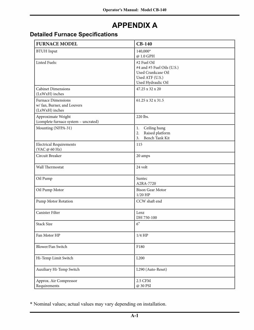
Operator's Manual: Model CB-140
A-1
APPENDIX ADetailed Furnace Specifications
* Nominal values; actual values may vary depending on installation.
FURNACE MODEL CB-140BTUH Input 140,000*
@ 1.0 GPHListed Fuels: #2 Fuel Oil
#4 and #5 Fuel Oils (U.S.)Used Crankcase OilUsed ATF (U.S.)Used Hydraulic Oil
Cabinet Dimensions(LxWxH) inches
47.25 x 32 x 20
Furnace Dimensionsw/ fan, Burner, and Louvers(LxWxH) inches
61.25 x 32 x 31.5
Approximate Weight(complete furnace system – uncrated)
220 lbs.
Mounting (NFPA-31) 1. Ceiling hung2. Raised platform3. Bench Tank Kit
Electrical Requirements(VAC @ 60 Hz)
115
Circuit Breaker 20 amps
Wall Thermostat 24 volt
Oil Pump SuntecA2RA-7720
Oil Pump Motor Bison Gear Motor1/20 HP
Pump Motor Rotation CCW shaft end
Canister Filter LenzDH 750-100
Stack Size 6”
Fan Motor HP 1/4 HP
Blower/Fan Switch F180
Hi-Temp Limit Switch L200
Auxiliary Hi-Temp Switch L290 (Auto-Reset)
Approx. Air CompressorRequirements
2.5 CFM@ 30 PSI
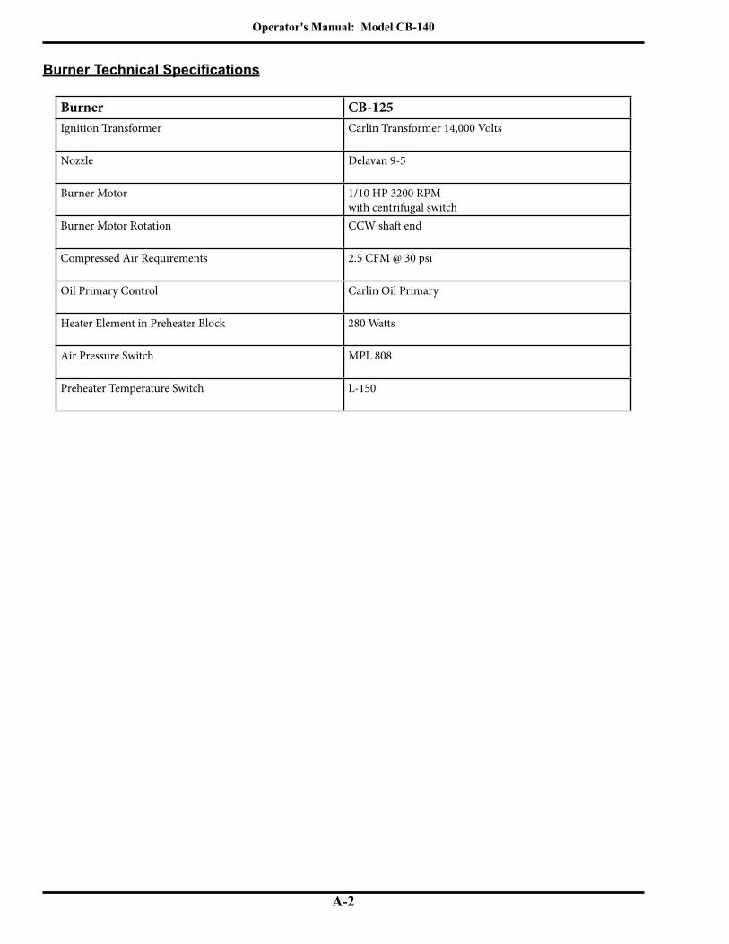
Operator's Manual: Model CB-140
A-2
Burner Technical Specifications
Burner CB-125Ignition Transformer Carlin Transformer 14,000 Volts
Nozzle Delavan 9-5
Burner Motor 1/10 HP 3200 RPMwith centrifugal switch
Burner Motor Rotation CCW shaft end
Compressed Air Requirements 2.5 CFM @ 30 psi
Oil Primary Control Carlin Oil Primary
Heater Element in Preheater Block 280 Watts
Air Pressure Switch MPL 808
Preheater Temperature Switch L-150

Operator's Manual: Model CB-140
A-3
CB-140 Dimensions
I89105-A
MOUNTING HOLE DIMENSIONS47.25" 10.38
9.5"
20"
39.25" 6.62"
26"
32" 29.5"
28"

Operator's Manual: Model CB-140
A-4
FIGURE A1 - Burner Component Detail
Burner Components
I89137
7
6
5
43
21
2322216
2019
18 17
16 15 14
1311
10
129
8
24

Operator's Manual: Model CB-140
A-5
Burner Components (continued)ITEM# PART# DESCRIPTION1 26136 COVER LH 1252 26135 COVER RH 1253 33247 TERMINAL BLOCK4 14088 CONNECTOR RECEPTACLE5 11308 RETENTION HEAD6 26078 LID TAB7 11633 HOUSING CB 125 A.8 33400 PRIMARY - 30 SEC, 4 WIR9 33175 BLOWER MOTOR10 26044 MOTOR MOUNTING PLATE11 31113 FAN SQUIRREL CAGE12 12159 BLOWER MOTER ASSEMBLEY13 26141 COVER MOTOR 12514 33297 HOUR METER, 60 Hz15 33168 AMBER LIGHT (PUMP)16 33169 GREEN LIGHT (POWER)17 11359 AIR INLET INNER PLATE18 26103 AIR INLET OUTER PLATE19 13183 HEATER BLOCK CB 125 A.20 33105 SNAP BUSHING21 33116 CAD CELL22 26056 CAD EYE BRACKET23 31284 HINGE AL 1.5 X 4.2524 33189 ELECTRIC IGNITER

Operator's Manual: Model CB-140
A-6
Burner Components (continued)
FIGURE A2 - Preheater Block Assembly Component Detail
45 46 47 48
2
1
3
4
5
65
7
8
910
11121314
1516
1718
1920
521
22
28
25
26
27
43
44
22
41
38
39
40
5
24
23
29 3031323334353637
42
I89136
49

Operator's Manual: Model CB-140
A-7
Burner Components (continued)
ITEM# PART# DESCRIPTION1 32000 NOZZLE 9-52 34436 MS Pan HD 10-32X5/8Z3 26134 SUPPORT NOZZLE HOLDER4 26140 GUIDE5 32199 PLUG,HEX SOC, 1/16 NPT6 33455 TEMPATURE SWITCH L-1507 33041 PROVING SWITCH 120D N.O.8 33321 NUT9 33319 COIL10 33320 COIL HOUSING11 33318 WASHER SEAL12 33317 FLUXPLATE13 33316 PLUNGER GUIDE ASSEMBLY14 33315 PLUNGER ASSEMBLY15 33314 BODY “O” RING16 33313 MANIFOLD MOUNT SOLENOID BODY17 33312 SOLENOID OUTER”O” RING18 33311 SOLENOID INNER”O” RING19 33057 AIR PRESSURE SWITCH20 33298 140 WATTS HEATER21 26142 SUPPORT BLOCK 12522 32505 1/8X 2 1/2 RND BRS NIPPLE23 32042 ST EL 90 1/8F 1/8M NPT24 32007 PLUG,HEX SOC., 1/8 NPT25 32179 SQ. AIR GAUGE, 0-60 PSI26 32049 PIPE THD ADPTOR, 1/8 NPT27 32202 FEMALE ELBOW (3/8 OIL LINE)28 32531 1/8 NPT COUPLING BRASS29 32178 SQ. OIL GAUGE, 0-15 PSI30 32221 POPPET SPRING31 32222 POPPET VALVE32 32223 POPPET “O” RING33 32305 BRASS POPPET SEAT34 32225 DIAPHRAGM35 32226 DIAPHRAGM RING36 32227 COMPRESSION SPRING37 32228 SPRING DISC38 33308 BONNET39 34022 NUT, 10-3240 33310 THREADED KNOB41 13142 REGULATOR KIT COMPONENTS42 32285 AIR REGULATOR43 32201 FEMALE ELBOW (3/8 OIL LINE)44 34070 SET SCREW 1/4 X 1/445 32322 AIR/OIL SOLENOID ASSEMBLY46 34326 SCREW 10-32 X 7/847 34165 BONDED WASHER48 33183 SINGLE PIECE ELECTRODE49 26130 HEATER BLOCK CB 125

Operator's Manual: Model CB-140
A-8
Burner Components (continued)
FIGURE A3 - Burner Electrode Component Detail
BURNER NOZZLE
NOZZLE IS STAMPEDEITHER 9-5 OR -5 ON
FLAT OF NOZZLE HEAD
SIDE VIEW - AA
3/16" GAP BETWEENELECTRODES & NOZZLE
CRITICAL DIMENSION:NOZZLE MUST BE 1/8"
AHEAD OF THE DISK.NOZZLE MUST NOT BE
BEHIND THE DISK.
1/8"SPARK
GAP
VIEW - AA
VIEW - BB
3X
I88340-B
SIDE VIEW - BB

Operator's Manual: Model CB-140
A-9
HEAD DISTRIBUTOR STEM
ORIFICE O-RING
NOZZLE SIZE ISSTAMPED ON
FLAT OFNOZZLE HEAD
I88378
Burner Components (continued)
Removing the Nozzle for Cleaning:
1. Remove the lock-down nut on the mounting flange bolt.2. Disconnect power from the burner.3. Carefully swing the burner open to its maintenance position.4. Remove the nozzle from the nozzle adapter with a 5/8" socket.
Cleaning the Nozzle:
1. Unscrew the stem from the nozzle head.2. Spray WD-40 or equivalent through the orifice to thoroughly remove any blockage.3. ATTENTION: DO NOT damage or deform the nozzle orifice; DO NOT use a torch
tip cleaner or other inappropriate device to clean the orifice. If the blockage is a "tarry" material or a hard, black material, call your Clean Burn dealer for service.
4. Flush all components with WD-40 to remove oil residues.5. Reassemble the nozzle components. When tightening the stem, just barely "snug" it
down. DO NOT overtighten.
6. Check the O-ring on the nozzle stem. Replace the O-ring if it is in the least bit cut or deformed.
7. Lubricate the O-ring on the nozzle stem with a couple of drops of new motor oil, then re install the nozzle.
8. Check the electrodes for proper gap and clearances.9. Re-install the burner and adjust for optimal performance as described in Section 6.
NOTE: If the nozzle plugs within a few days after cleaning, call your Clean Burn Dealer for service.
FIGURE A4 - Cleaning the Nozzle
Model Nozzle SizeCB-125 Delavan 9-5

Operator's Manual: Model CB-140
A-10
CB-140 Cabinet Components
3
4
5
6
910
1314
16
11
17
19
18
20
21
1
23
25
26
27
28
3837
45
46
30
31
39
40
41
42CB-140
2
22
44
47
7
29
DETAIL B
11
48
24
33
35
34
36
32
1512
11
I89107-A
43
8 (OPTIONAL)
DETAIL A
34
33
B
A

Operator's Manual: Model CB-140
A-11
CB-140 Cabinet Components (continued)
ITEM # PART # DESCRIPTION1 29212 SHROUD TOP 1402 29210 SHROUD REAR 1403 70479 DUCT CAP 6" 24 GA GALV4 29146 BREECH 6"5 23093 FLUE TUBE 3X33.756 34191 3/8-16 X 3/4 CARRIAGE BOLT7 29149 LOUVER 1408 90244 AIR DISCHARGE HOOD 140 A9 21185 COMBUSTION SLEEVE & FEET 140 A10 34119 3/8-16 X 3 HHCS GR-2 ZINC11 34118 5/16-18 X 3/4 HEX WASHER HEAD12 34095 3/8-16 STOVER L/N13 21056 HINGE BRACKET GALV14 11582 HINGE BRKT 3DEG BURNER WA - USE W 11583 MOUNT15 14343 CB-125 HOOK-UP A16 34120 5/16-18 X 2 3/4 CARR BOLT SS17 11583 BURNER MOUNT 3 DEG WA - USE WITH 11582 BRACJET18 21076 PORT CAP19 11325 INSPECTION DOOR A20 29211 DOOR 14021 31275 INSULATINO DOOR 14022 12314 SLEC PRIME SW BOX A23 33336 CONNECTOR PLUG24 33273 CONNECTOR 90 DEG SNAP-TITE (3/8 FLEX CONDUIT)25 33286 SWITCH DPDT ON-ON26 33486 TERMINAL BLK A27 21183 E-BOX FOR PRIME SWITCH28 21184 E-BOX COVER29 34051 5/16-18 X 1 1/2 HHCS ZINC30 21101 CONNECTOR BLOCK31 32039 ADAPT 1/4 OD X 1/8 P32 13188 AIR LINE 125 A33 32304 NUT LONG 3/8 COMP34 32303 SLEEVE 3/8 COMPRESSION35 13187 OIL LINE 125 A36 32245 SWIVEL 1/4 NPTM, 1/4 NPTF37 12057 FLEX CONDUIT RW 3/8 X 23 1/238 29090 SWITCH COVER39 33288 AUXIL HI LIMIT-AUTO RESET 29040 29064 MOUNT FAN START SWITCH41 33230 FAN - TEMP SWITCH42 33390 SWITCH TEMP (HL)43 29067 BRACKET TEMP HI LIMIT44 12308 140 FAN ASSEMBLY45 33586 MOTOR - 1/4 HP FAN46 31125 FAN GUARD47 31274 FAN 3-BLADE 20 IN DIA 20 DEG PITCH48 21057 HINGE BRACKET GALV 11589 CB 140 FURNACE WA

Operator's Manual: Model CB-140
A-12
Metering Pump Components
I89112-A
2
10
9
3
12
11
14
GAUGEINLET
ROTATION
NI
OUT
13
27
15
1
28
16
23
24
26
25
24
23
17 16
22
21
20
19
18
PACKAGED WITHCLEAN BURN EQUIPMENT
PACKAGED WITHCLEAN BURN EQUIPMENT
29
A2RA - 7710
GAUGE
INLET R.H. ROTATION
INLET
3031
SINGLE PIECE OFCOPPER TUBING(USER SUPPLIED)
7 4
8
SUPPLYTO BURNER
6 5
RETURNTO TANK
RELIEF

Operator's Manual: Model CB-140
A-13
Metering Pump Components (continued)
ITEM # PART # DESCRIPTION1 33363 CAPACITOR2 33291 GEAR MOTOR CB-1403 11322 MOUNT METER PUMP A4 32037 1/8 NPT X 1/4 TUBE COMPRESSION FITTING5 N/A 1/4 COPPER OR ALUMINUM TUBING6 N/A 3/8 OR 1/2 TUBE FLARE NUT7 N/A 3/8 0R 1/2 COPPER OR ALUMINUM TUBING8 N/A 1/8 M NPT X 3/8 OR 1/2 FLARE9 32526 MINI BALL VALVE 1/8 MNPT X 1/8 FNPT10 32475 PUMP-METERED OIL11 32467 NIPPLE 1/4 NPT X 3 ROUND BRASS12 32210 ST EL 90 1/4F-1/4M NPT13 32336 BUSHING 3/4 X 1/4 BR.14 32123 GAUGE (LENZ)15 32127 CANISTER FILTER16 32430 BUSHING 3/4" X 1/2"17 32446 NIPPLE 1/2 X 5"-BRASS18 32429 TEE 1/2" BRANCH19 32137 EXTERNAL PIPE ADAPTER20 32142 BALL VALVE 1/2 NPT21 32062 MALE CONNECTOR 1/4 TUBE22 32443 BUSHING 1/4 X 1/2" BRASS23 32141 FLARED TUB.TO PIPE STRAIGHT24 32140 LONG NUT 1/225 32139 TUBE TO PIPE MALE STRAIGHT26 32442 BUSHING DUPLEX SLIP THRU27 32021 CHECK VALVE28 32061 CHECK VALVE SCREEN 3/4"29 32445 PIPE CAP 1/2"-BRASS30 32423 SCREEN PUMP (M PUMP)31 32422 GASKET COVER (M PUMP)
33297 HOUR METER (60 Hz) 21182 MTR PUMP COVER FOR HOUR METER 13176 SUCTION FITTINGS PACKAGE

Operator's Manual: Model CB-140
A-14

Operator's Manual: Model CB-140
B-1
APPENDIX B
FIG
UR
E B
1 - C
B-1
40 F
urna
ce W
irin
g D
iagr
am
Wiring Diagrams
120
VAC
PUM
P
POW
ER IN
BRAC
KET
ON
CO
NTR
OL
HIG
HLI
MIT
AUTO
AUX.
(TEM
P)
HIG
HLI
MIT
HO
T (B
LK)
NEU
T (W
HT)
BLAC
K
OIL
WH
ITE
L2
GRN
D
L1
R/W
HT
Red / Wht HT
Red / Wht HT
WHITE
CON
NEC
TOR
RED
MO
UN
TED
FAN
(TEM
P)
SURF
ACE
SWIT
CH
FACE
Blk
/ Wht
HT
BLK
RED
BLK
WH
T
3 GRN
6
GRNW
HT
TO B
LOW
ER
1 2
4 5
L2 4 53L2L1L1RU
NBU
RNER
PRIM
EPU
MP
Blk
/ Wht
HT
BLK PURP
LE
CB-1
40I4
2451

Operator's Manual: Model CB-140
B-2
FIGURE B2 - CB-125 Burner Wiring Diagram
NO
TE
: Th
e C
B-1
25 p
rimar
y co
ntro
ller i
s a re
cycl
e ty
pe c
ontro
l with
four
wire
s and
feat
ures
inte
rrup
ted
igni
tion
oper
atio
n.
Wiring Diagrams (continued)
CAPA
CITO
R
BURN
ER
MO
TOR
140 W HEATER
FORM
ER
TRA
NS-
RED
SOLE
NO
IDA
IR
SOLE
NO
IDO
IL
JUM
PERS
13
24
AM
BER
LIG
HT
116
57
98
1012
13
WHITE
GRE
ENBLAC
K
MET
ER
HO
UR
RED
(OPT
ION
AL)
COM
PRES
SOR
AIR
BLU
E
BRO
WN
140 W HEATER
PREH
EATE
R TH
ERM
OST
AT
ORA
NG
E
PRO
VIN
G S
WIT
CH 1
20° N
.O.
BLAC
K
SWIT
CHA
IR
N.O
.
WH
ITE
CAD
CEL
LYE
LLO
W
YELL
OW
BLU
E
BROWN
WH
ITE
RED
BLU
E
WH
ITE
BLAC
K
BLACK
BLACK
WHITEG
REEN
LIG
HT
CON
NEC
TOR
(FAC
E)
RED
BLAC
K
CB-1
25I4
2538
OIL
PRIM
ARYF
FT
T
CARL
IN

Operator's Manual: Model CB-140
B-3
FIGURE B3 - Ladder Schematic for CB-140 with CB-125 Burner (120 Volts / 60 Hz)
HI LIMIT TEMP SWITCH N/C
CENTRIFUGAL SWITCH
SERVICESWITCH
CUSTOMER POWER - CONNECTION TO
WHT
GRN
WHT
GRN RD
BK
BK
RD
DISCONNECTOPTIONAL
WHT OILPRIMARYCONTROL
AIR COMPRESSOR (OPTIONAL)
250 WATTS BLOCK HEATERBLOCK TEMP. SWITCH
BURNER MOTOR
AIR PRESSURE
BL
POWER ONG
OIL SOL.
AIR SOL.
U
R
NE
R
B
MODEL CB-140
PROVING SWITCH120°
CADCELL
BK F F
HOT NEUTRAL
THERMOSTATWALL
T T
OIL PUMP MOTOR
I44125
FAN SWITCH(METAL SURFACE: 33230)
FAN MOTOR
(ON METAL SURFACE:33390)SECONDARY TEMP SWITCH N/C
(ON METAL SURFACE:33288)
FURNACE
DRAFT INDUCERMOTOR (OPTIONAL)
150°
OR
IGNITION TRANSF.
SPARK GAP
3M
M 2
M 1
PRIME BURNER
TOGGLE SWITCHON FURNACE CABINETTOGGLE DOWN : BURNERTOGGLE UP : PRIME
D P D T

Operator's Manual: Model CB-140
B-4
Figure B4 - Metering Pump Wiring Schematic
Wiring Diagrams (continued)
I42533
ENCLOSED J-BOX
* 115 V 60 HZ POWER FROM OIL PUMP CIRCUITSEE FURNACE SCHEMATIC
RED
GRN
BLK
BLUE
BLK
BLKCA
P.
*
GROUND
L 1 (BLK)
L 2 (WHT)
METERHOUR
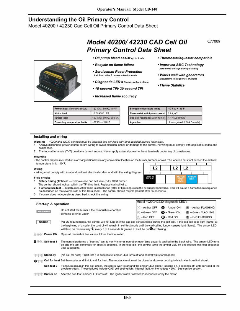
Operator's Manual: Model CB-140
B-5
Model 40200/ 42230 CAD Cell Oil Primary Control Data Sheet
• Oil pump bleed assist up to 1 min.
• Serviceman Reset Protection Latch-up after 3 consecutive lockouts
• Diagnostic LED’s
• 15-second TFI/ 30-second TFI
L2 L2 L2
LIMIT IN120V, 60 HZ
LINE HEAT-
ER
MOTOR10FLA 60LRA
IGNITOR500VA
VALVE
• Thermostat/aquastat compatible
• Improved SMC Technology zero bleed voltage during standby
• Works well with generators Insensitive to frequency changes
• Flame Stabilize
Model 40200/42230 diagnostic LED’s
– Amber OFF – Amber ON – Amber FLASHING
– Green OFF – Green ON – Green FLASHING
– Red OFF – Red ON – Red FLASHING
Installing and wiringWarning — 1. Always disconnect power source before wiring to avoid electrical shock or damage to the control. All wiring must comply with applicable codes and
ordinances.2. Thermostat terminals (T–T) provide a current source. Never apply external power to these terminals under any circumstances.
Mounting• The control may be mounted on a 4” x 4” junction box in any convenient location on the burner, furnace or wall. The location must not exceed the ambient temperature limit, 140°F.
Wiring• Wiring must comply with local and national electrical codes, and with the wiring diagram.
Field checks1. Safety timing (TFI) test — Remove one cad cell wire (F-F). Start burner. The control should lockout within the TFI time limit. Replace cad cell wire.2. Flame failure test
as described on the reverse side of this Data sheet. The control should recycle (restart after 65 seconds).3. If control does not operate as described, check the wiring.
Start-up & operation Do not start the burner if the combustion chamber
contains oil or oil vapor.
The amber LED
every 3 to 4 seconds & green LED will be on or blinking.
Power ON Open all manual oil line valves. Close the line switch.
Self-test 1 The control performs a “boot-up” test to verify internal operation each time power is applied to the black wire. The amber LED turns on and the test continues for about 5 seconds. If the test fails, the control turns the amber LED off and repeats this test sequence until successful.
Stand-by (No call for heat) If Self-test 1 is successful, amber LED turns off and control waits for heat call.
Call for heat Set thermostat and limit to call for heat. Thermostat circuit must be closed and power coming to black wire from limit circuit.
Self-test 2 If a failure occurs in this self-check, the control won’t start and the amber LED blinks 1 second on, 4 seconds off, until serviced or the problem clears. These failures include CAD cell seeing light, internal fault, or line voltage <90V. See service section.
Burner on After the self-test, amber LED turns off. The ignitor starts, followed 2 seconds later by the motor.
Power input (from limit circuit) 120 VAC, 60 HZ, 10 VA
Motor load 10 FLA/ 60 LRA
Ignitor load 120 VAC, 60 HZ, 500 VA
Operating temperature limits +32°F to +140°F
Storage temperature limits -40°F to +185°F
Thermostat anticipator current 0.1 A, AC
Cad cell resistance R < 1500 OHMS
Agencies UL recognized (US & Canada)
C77009
Understanding the Oil Primary ControlModel 40200 / 42230 Cad Cell Oil Primary Control Data Sheet

Operator's Manual: Model CB-140
B-6
Pump Prime To enter pump prime: 1. Start a CFH cycle. During Pre-Ignition or Pre-Purge, press Reset until motor turns off (10 seconds), then
in Pump Prime, release Reset button.
Optional Pump Prime notes: 1) If lost, press Reset for 1 second and release, then if the control is not in Pump Prime, restart the se-
Reset button is pressed.
TFI
Run The burn
Lockout lockout occurs. The control turns the red LED on constant, and closes the alarm contact.
To Reset Push in and hold reset button for 2 seconds, then release.
Latch-up If the control locks out 3 times during a single call for heat, latch-up occurs. The control turns on both the amber and red LED’s con-stant. You must use the special procedure below to reset the control after latch-up.
repeated burner lockouts must be corrected before returning the burner to normal operation.
the control will restart (releasing the button before the LED’s turn off will cause the control to remain in latch-up).
The 40200 & 42230 controls will retain lockout or latch-up if power is interrupted.
Flame failure Recycle: Control waits for 65 seconds (with f .
Stand-by Control remains in stand-by mode until limit circuit sends power to the black wire and thermostat circuit closes (call for heat).
Service & Troubleshooting
Burner (control) will not come onNo power to control
• Check limit circuit to the control (at least 102 VAC).• Check all electrical connections.
Control is in lockout• Red LED will be on. Press the reset button for 2 seconds.
CAD cell seeing light• Green LED on, and amber LED blinking 1 second on, 4 seconds
off. Remove one yellow lead from FF terminals. If the amber LED
If the amber LED goes OFF, the control is OK, and;• light is leaking into the burner housing, OR
• CAD cell is defective, OR
• there is a problem with the CAD cell wiring or holder.• If appliance was recently shut down, CAD cell may see residual
hot spots in chamber. To troubleshoot:
• Attach multimeter to monitor CAD cell resistance. Dark resistance should be over 50K ohms, and room light resis-
Replace cell if necessary, or reinstall and close the burner housing.
• Check for stray light by measuring the CAD cell resistance looking into the inactive combustion chamber. It should read
at least 50 KOHMS.
Other no start problems
If the CAD cell is OK, and the amber LED still blinks 1 second on, 4 seconds off, the other possible failures include:
• on, 1/2 second off, 1 second on, 3 seconds off, then repeats). Check line voltage.
• Internal fault: CAD cell, and line voltage OK, the issue may be an internal fault . Replace the control.
Check for: • CAD cell is defective. Replace.• -
• •
check for proper air band setting and draft.•
Control locks out at end of TFI ( red LED on)
Check for: • • Shorted electrodes- inspect for cracked porcelain and replace
as needed.• Poor spark- check electrode spacing and condition per burner
manual. Replace or realign if necessary.• Nozzle clogged- replace nozzle.• • Ignitor module defective- replace if no spark.• CAD cell defective• Oil valve (if used) stuck in closed position.• Check wiring connections.
Start-up & operation continued... C77010
Understanding the Oil Primary Control (continued)Model 40200 / 42230 Cad Cell Oil Primary Control Data Sheet
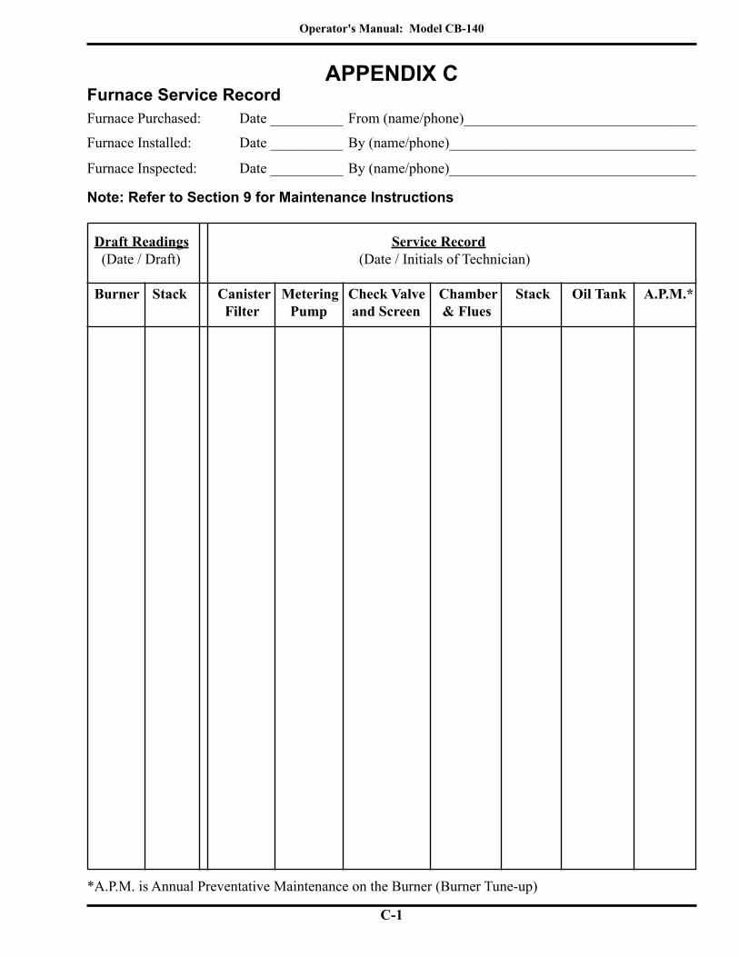
Operator's Manual: Model CB-140
C-1
Furnace Service RecordAPPENDIX C
*A.P.M. is Annual Preventative Maintenance on the Burner (Burner Tune-up)
Furnace Purchased: Date __________ From (name/phone)________________________________
Furnace Installed: Date __________ By (name/phone)__________________________________
Furnace Inspected: Date __________ By (name/phone)__________________________________
Note: Refer to Section 9 for Maintenance Instructions
Draft Readings Service Record (Date / Draft) (Date / Initials of Technician)
Burner Stack Canister Metering Check Valve Chamber Stack Oil Tank A.P.M.* Filter Pump and Screen & Flues

Operator's Manual: Model CB-140
C-2