fusing of pv arrays - emc | fuseco · fusing of pv arrays presented by nigel wilmot ... – 4...
TRANSCRIPT

© RISE, Murdoch University 2007 1
Fusing of PV arrays
Presented by Nigel WilmotOscar Arteaga, Andrew Ruscoe
And Martina Calais (Murdoch University)
2
Overview
– AS5033 requirements– Module and Array Faults – Protection Schemes– Fuse characteristics and test results– PV Module Characteristics– Fuse selection and module characteristics

© RISE, Murdoch University 2007 2
3
AS5033 Installation of photovoltaic arrays
General installation requirements for PV Arrays– 600V between positive and negative conductors– +/- 600V wrt earth
Provides requirements for protection of arrays in addition to AS/NZS3000 protection requirements
International draft IEC 62548 is based on AS5033
4
Faults in arrays
Failures in PV Modules due to– Overloading– Overheating– Mechanical
Typical Causes– Reverse current– Shading– Earth faults– Short circuits:- modules, junction boxes or module wiring– Backfeeding– Incorrect installation (reversed string or module)– Storms & projectiles
© RISE, Murdoch University 2007 3
5
Consequences of not protecting modules
Degradation of module performanceDegradation of parts
– Cells– Interconnects– Junction boxes
Failure of partsArcingFire
6
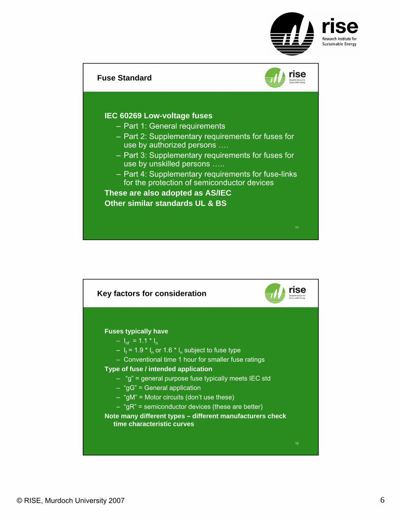
AS5033 Protection requirements
Bypass diodes– normally fitted by
manufacturerBlocking diodes
– are not a substitute for fault current protection.
– Refer to AS5033 section 2.3 for ratings of diodes
Fault Current Protection– (Next slide)
Blocking Diode
Bypass Diode

© RISE, Murdoch University 2007 4
7
Fault Current Protection
AS5033 Section 2.4 covers the requirements.
Discrimination – lower levels trip first
String protection is related to Module Reverse current rating (refer AS5033 Table 2.1)
Defines when and how large the sub array and array protection is required
8
PV Protection Current Rating
For strings where no manufacturer rating (AS5033 2.4.3)or
PV array (AS5033 2.4.4)or
PV sub array (AS 5033 2.4.5)Use Itrip
More than 1.25 x IscLess than 2 x Isc

© RISE, Murdoch University 2007 5
9
Fuses
Fuse ratings– Breaking Capacity– Voltage Rating (Vn)
– Rated current (In) – Note temperature current derating
– Conventional Non-Fusing Current (Inf)– Conventional Fusing Current (If)– Pre-arcing time (Joule Integral I2t)
10
Fuse time characteristic curve
10s
10s19 A
30 A
© RISE, Murdoch University 2007 6
11
Fuse Standard
IEC 60269 Low-voltage fuses – Part 1: General requirements– Part 2: Supplementary requirements for fuses for
use by authorized persons …. – Part 3: Supplementary requirements for fuses for
use by unskilled persons ….. – Part 4: Supplementary requirements for fuse-links
for the protection of semiconductor devicesThese are also adopted as AS/IECOther similar standards UL & BS
12
Key factors for consideration
Fuses typically have– Inf = 1.1 * In– If = 1.9 * In or 1.6 * In subject to fuse type– Conventional time 1 hour for smaller fuse ratings
Type of fuse / intended application– “g” = general purpose fuse typically meets IEC std– “gG” = General application– “gM” = Motor circuits (don’t use these)– “gR” = semiconductor devices (these are better)
Note many different types – different manufacturers check time characteristic curves

© RISE, Murdoch University 2007 7
13
Conventional use of fuses
Protection and safetyTypically
– Used with sources having high fault (kA) capability– Protection of cabling and traditional circuit
components– Used to avoid fires in installation– Equipment designs attached are “fail safe” (ie
meets AS 3100 or similar standard)
14
Example of String Protection
Following slides depict PV Application of fusesProtection against string faultsIgnores any other sources (grid or batteries)
– i.e. low fault current situationExample uses a BP Solar Module, however, other
module manufacturers recommend a similar fuse rating for their modules.

© RISE, Murdoch University 2007 8
15
PV Strings – Rated Trip Current
As per manufacturer
16
For BP 4175: Isc = 5.5A, Imod reverse = 16.5A,(Imodreverse / Isc) = 3 therefore np = 4 (table 2.1)
Explanatory Example
5.5A11A16.5A22.0A

© RISE, Murdoch University 2007 9
17
5.5A11A
BP 4175 - Isc = 5.5A, Imod reverse = 16.5A,Use say a 10 Amp fuse
Solution – Use Fuse
16.5A22.0A0 A
18
Review time characteristic curve
0.6s
100s22 A
22 A

© RISE, Murdoch University 2007 10
19
What can a PV Module handle
Swiss and German research shows:– Reverse currents (IR) up 3 time Isc no change IV
curve– Thermal losses of 800 to 900 W/m2
– With 1000 W/m2 radiation typical cell temperature increase 50C
– Max cell operating temperatures of 90 -100 C– Crystalline silicon cells
20
What can’t a PV Module handle
Swiss and German research shows:– Reverse currents (IR) up 7 time Isc results in
permanent damage after short time– Cell temperatures reached over 150C– Damage to EVA encapsulation– Damage to internal connections
© RISE, Murdoch University 2007 11
21
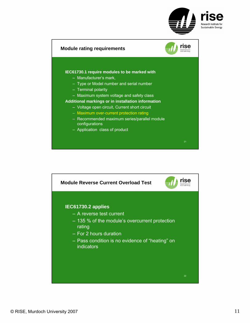
Module rating requirements
IEC61730.1 require modules to be marked with– Manufacturer’s mark, – Type or Model number and serial number– Terminal polarity– Maximum system voltage and safety class
Additional markings or in installation information– Voltage open circuit, Current short circuit– Maximum over-current protection rating– Recommended maximum series/parallel module
configurations– Application class of product
22
Module Reverse Current Overload Test
IEC61730.2 applies– A reverse test current– 135 % of the module’s overcurrent protection
rating– For 2 hours duration– Pass condition is no evidence of “heating” on
indicators
© RISE, Murdoch University 2007 12
23
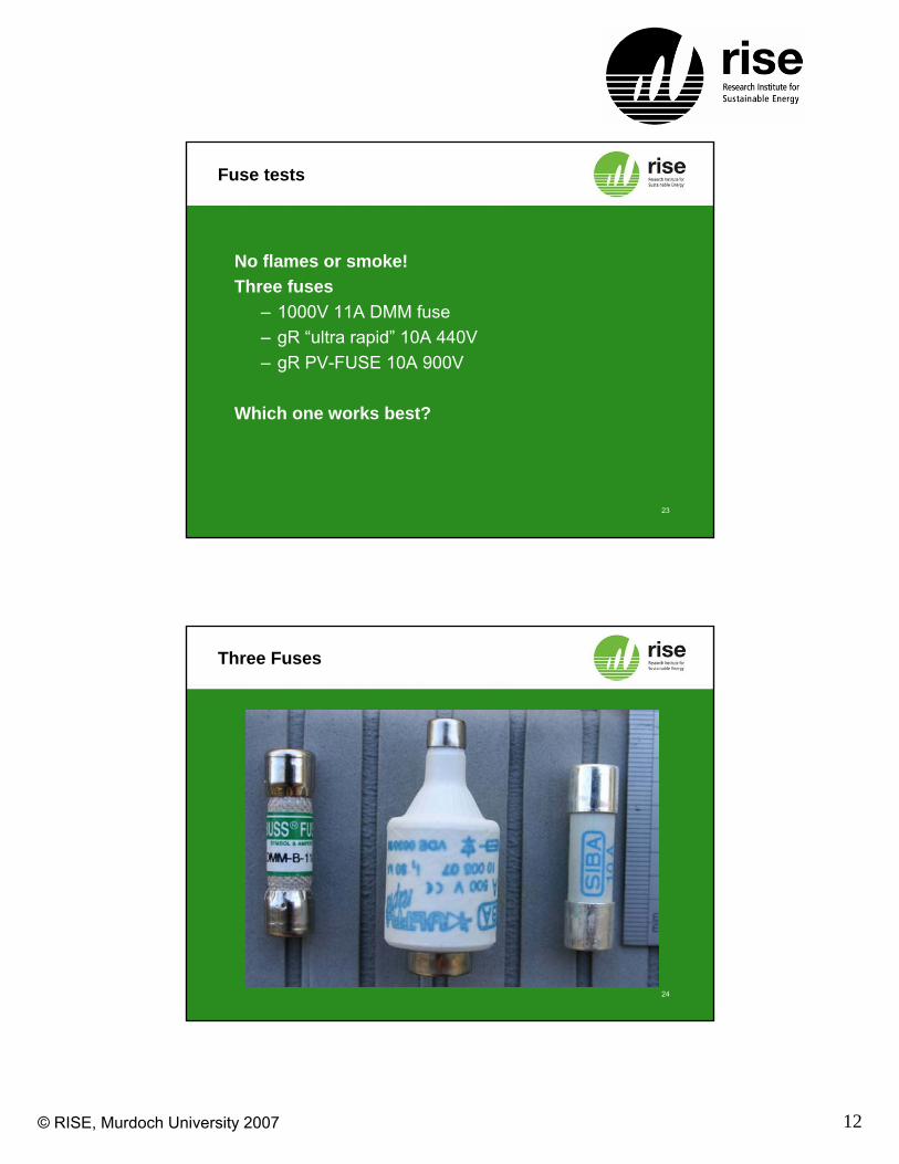
Fuse tests
No flames or smoke!Three fuses
– 1000V 11A DMM fuse– gR “ultra rapid” 10A 440V– gR PV-FUSE 10A 900V
Which one works best?
24
Three Fuses

© RISE, Murdoch University 2007 13
25
Specifications
100 000 A440 V10 ASIBA
Ultra RapidgR
30 000 A900 V10 ASIBA
PV-FusegR
20 000 A1000 V11 ABussmannDMM-B-11A
Breaking Capacity
Vn
DCInFuse
26
Current source Results
The setup– 60V 100 A Power supply – Current control mode– Applied voltage limit 50 V – Short circuit across fuse
What is a suitable response time?

© RISE, Murdoch University 2007 14
27
Time results (current source)
0.001
0.01
0.1
1
10
100
1000
10000
10 100
Current (Amps)
Pre
Arc
Tim
e (s
ec)
10A Ultra specUltra exp11A DMM specDMM exp10A PV specPV exp
20 30 40 50
28
Real Array Results
The setup– 4 strings of BP275’s– 15 module in series – 300 V open circuit– Short circuit across fuse– Real sunshine conditions
What is a suitable response time?
© RISE, Murdoch University 2007 15
29
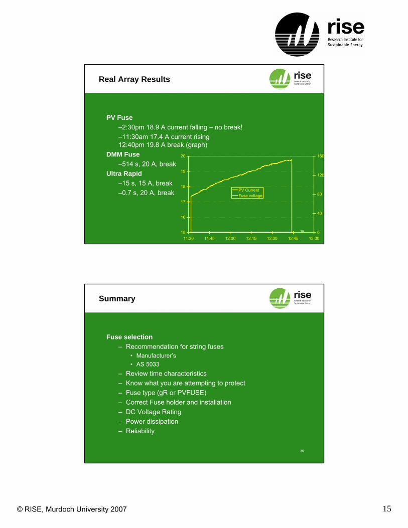
Real Array Results
PV Fuse–2:30pm 18.9 A current falling – no break!–11:30am 17.4 A current rising 12:40pm 19.8 A break (graph)
DMM Fuse–514 s, 20 A, break
Ultra Rapid–15 s, 15 A, break–0.7 s, 20 A, break
15
16
17
18
19
20
11:30 11:45 12:00 12:15 12:30 12:45 13:000
40
80
120
160
PV CurrentFuse voltage
30
Summary
Fuse selection– Recommendation for string fuses
• Manufacturer’s• AS 5033
– Review time characteristics– Know what you are attempting to protect– Fuse type (gR or PVFUSE)– Correct Fuse holder and installation– DC Voltage Rating– Power dissipation– Reliability

© RISE, Murdoch University 2007 16
31
Summary
Standards Development– Recommendation for string fuses?– 1.25×ISC MOD ≤ ITRIP ≤ 2×ISC MOD
• IEC draft 1.4 × ISC MOD ≤ ITRIP ≤ 2.4 × ISC MOD
– What is the definition of ITRIP• Fuse rated current (as it is now)• Conventional Non fusing current• Conventional fusing current