fw102b motorized filter wheel - thorlabs
TRANSCRIPT

FW102B
Motorized Filter Wheel
Operating Manual
FW102B
16667-D02, Rev C 5/17/2010 Page 2 www.thorlabs.com
Table of Contents
Part 1. Description ........................................................................................................................................ 4
Part 2. Basic Operation ................................................................................................................................. 5 Changing and Removing Filters ....................................................................................................................................... 5 Mounting ........................................................................................................................................................................... 5 Power ................................................................................................................................................................................ 5 Aperture ............................................................................................................................................................................ 5 Accessories ....................................................................................................................................................................... 6
2.1. Manual Control .............................................................................................................................................. 6
2.2. External Trigger ............................................................................................................................................. 6
2.3. Application Software Operation ................................................................................................................... 6 Establishing Communications with FW102B ................................................................................................................... 7 Programmed Sequence Operation (Scan Mode) ............................................................................................................... 8 Help................................................................................................................................................................................... 8
2.4. Command Line Interface .............................................................................................................................. 8 Keywords (Commands and Queries) .............................................................................................................................. 10 Software Installation ....................................................................................................................................................... 10 Minimum PC Requirements ........................................................................................................................................... 10
Part 3. Specifications .................................................................................................................................. 11 3.1. Performance.................................................................................................................................................. 11
3.2. Electrical ....................................................................................................................................................... 11
3.3. Physical Characteristics and Interface ....................................................................................................... 12
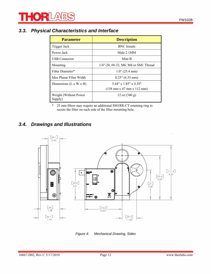
3.4. Drawings and Illustrations .......................................................................................................................... 12
3.5. Supplied Equipment ..................................................................................................................................... 14
Part 4. Regulatory ....................................................................................................................................... 16
Part 5. Thorlabs, Inc Worldwide Contacts ................................................................................................. 17
FW102B
16667-D02, Rev C 5/17/2010 Page 3 www.thorlabs.com
Table of Figures Figure 1: Software Screen Shot: Initial Startup Screen ......................................................................... 7 Figure 2: Software Screen Shot: Setting the Com Port ......................................................................... 7 Figure 3: Software Screen Shot: Changing the Filter Position.............................................................. 8 Figure 4: Mechanical Drawing, Sides ................................................................................................. 12 Figure 5: Mechanical Drawing, Top and Bottom ................................................................................ 13 Figure 6: Mechanical Drawing, Front ................................................................................................. 13

FW102B
16667-D02, Rev C 5/17/2010 Page 4 www.thorlabs.com
Part 1. Description The FW102B is a high precision motor driven filter wheel used for a host of applications including color CCD photography, fluorescence microscopy, and photometry.
The unit consists of a control unit, filter wheel housing, and a removable 4" diameter filter wheel. The filter wheel accommodates up to 6, 1" filters or optics. Filter selection can be made manually from the push button controls on the display panel or remotely from either a USB 2.0 interface or a TTL level active low (BNC) input. The FW102B contains an active display to indicate the selected filter and two unique aperture openings at the top and at 90°.
The unique design of the FW102B makes the filter locations very accurate and very repeatable.
The lightweight design provides easy mounting to optical instruments via two SM1 (1.035"-40) threaded mounts. Adaptors are available to interface to other popular camera, microscope and telescope thread sizes. The unit also has 1/4"-20 and M6 tapped holes for mounting to an optic table or breadboard. The flexible mounting system makes the FW102B ideal for both instrument and laboratory applications.
The unit comes with a CD-ROM which contains a Windows™ based standalone application program. In addition, LabWindows/CVI™ and LabVIEW™ instrument drivers are included to facilitate integrated instrumentation software development. The filter wheel can also be controlled via a set of command line prompts using terminal server software. This allows the user to also create scripts in their own programs.
The unit is powered from a low voltage 5 VDC input (converter supplied with the unit).
Features
• Automated Computer Control Capability (Application Software Provided) • Holds Six 1" Diameter Filters • External Trigger In (Increment Control) • External Trigger Out (Provisioned From Software) • Bidirectional Controls • 300 Millisecond Typical Access Time • Selectable Aperture Openings at 12:00 O’clock and 3:00 O’clock • Dimmable Display • MTF +2 Years Based on 75 wheel moves per hour, 8 hr day • Limited Use for Continuous Operation
™ LabWindows/CVI™ and LabVIEW™ are registered trademarks of National Instruments Corporation. Windows™ is a registered trademark of Microsoft Corporation. Pentium™ is a registered trademark of Intel Corporation.

FW102B
16667-D02, Rev C 5/17/2010 Page 5 www.thorlabs.com
Part 2. Basic Operation The following sections describe the basic operation of the motorized filter wheel and operation of the software.
Changing and Removing Filters
Warning Prior to changing filters, ensure that the power is off and the unit is disconnected
from the DC source.
The filters can be changed by first removing the filter wheel cover. Using the 5/64 hex key provided, remove the three button head hex screws shown in Figure 4:. Filters can now be inserted into the desired locations. Filters are secured to the wheel by inserting the provided the SM1RR-1CT retaining rings. Optionally, the entire filter wheel can be removed by unscrewing the locking knob Figure 6: after removing the cover. Please note that the rear edge of the threaded filter holes contain a retaining lip to secure one edge of a 1” filter, 25mm filters may require a SM1RR-1CT on each side of the filter.
When reattaching the filter wheel to the housing, align the guide pins from the housing to the guide holes on the wheel before attaching the locking knob. The unit will reorient after the first selection is made.
Mounting The base of the unit contains two sets of mounting holes a 1/4"- 20 and #8-32 set, and a metric M6 and M4 set for mounting to optical tables and breadboards, see Figure 5:. Note the metric set is closest to the indicator mark ‘o’. The filter wheel cover contains SM1 threads for attaching lens tubes or for mounting the FW102B directly to cameras, microscopes, and telescopes. Thorlabs sells a host of adapters for the SM1 threads.
Power The unit comes with an AC wall adapter to supply +5 VDC to the unit. Plug the 2.1 mm plug from the AC adapter into the DC input jack on the unit. The ON/OFF (0/1) switch is located on the side of the unit, shown in Figure 4:. Upon power up, the unit will display the filter number located at the selected aperture. If the wheel is not located at a valid location, it will rotate to position 1.
Aperture The unit has two aperture locations labeled “A” and “B” for the top and 90° positions respectively. The A/B switch on the side of the unit selects the aperture, see the figure on page 13.
In order to change the position after changing the aperture switch, the user must manually press either the up or down filter selection arrow. The aperture position
will not change when the toggle switch is changed.

FW102B
16667-D02, Rev C 5/17/2010 Page 6 www.thorlabs.com
Accessories The following is a list of items available from Thorlabs, which may complement the capabilities of the FW102B.
Item# Description SM1A9 Cmount to SM1 Adapter
SM1A3 RMS to SM1 Adapter
SM1RR SM1 retaining ring for holding optics and lenses in place
SPW602 Spanner wrench for SM1 series products
SM1L10 SM1 series lens tubes
DCU220 Series CCD camera with C-mount, use with SM1A10 Adapter
FL and FB Series Filters Family of bandpass filters
FG series filters Family of colored glass filters
NE and ND series filters Family of absorptive and reflective neutral density filters
XT66 series Family of rail mounting products
2.1. Manual Control Depressing the UP/DOWN arrow switches on the top of the unit (see the figure on page 13) will increment and decrement the filter location. The arrows also indicate the direction of rotation for the wheel and the display will indicate the filter selection. The display brightness can be adjusted using a small screwdriver at the hole marked DIM.
2.2. External Trigger The unit may be remotely triggered to advance to the next position. This is done by applying an active low pulse to the BNC trigger input. The input is TTL compatible and should not exceed 5 V. The input is internally pulled up; therefore the trigger will also operate with a passive connection to ground. The trigger mode defaults on power up to an input mode; however software provisioning can change the mode of the trigger to become an output trigger. In the output mode the unit generates an active high (TTL level, see specifications) 10 ms pulse to indicate the wheel has completed its rotation to the selected position. This pulse may be used to activate other equipment. The trigger can be changed to the output mode from the application software or by sending the command “Trig=1” over the USB interface (see command line interface).
2.3. Application Software Operation The FW102B comes with a CD-ROM containing application software to control the unit from a PC. After installing the software (see software installation), apply power to the unit. Connect a USB cable between the FW102B and a PC. To execute the FW102B standalone application, select Programs > Thorlabs > FW102B from the Start menu.
FW102B
16667-D02, Rev C 5/17/2010 Page 7 www.thorlabs.com
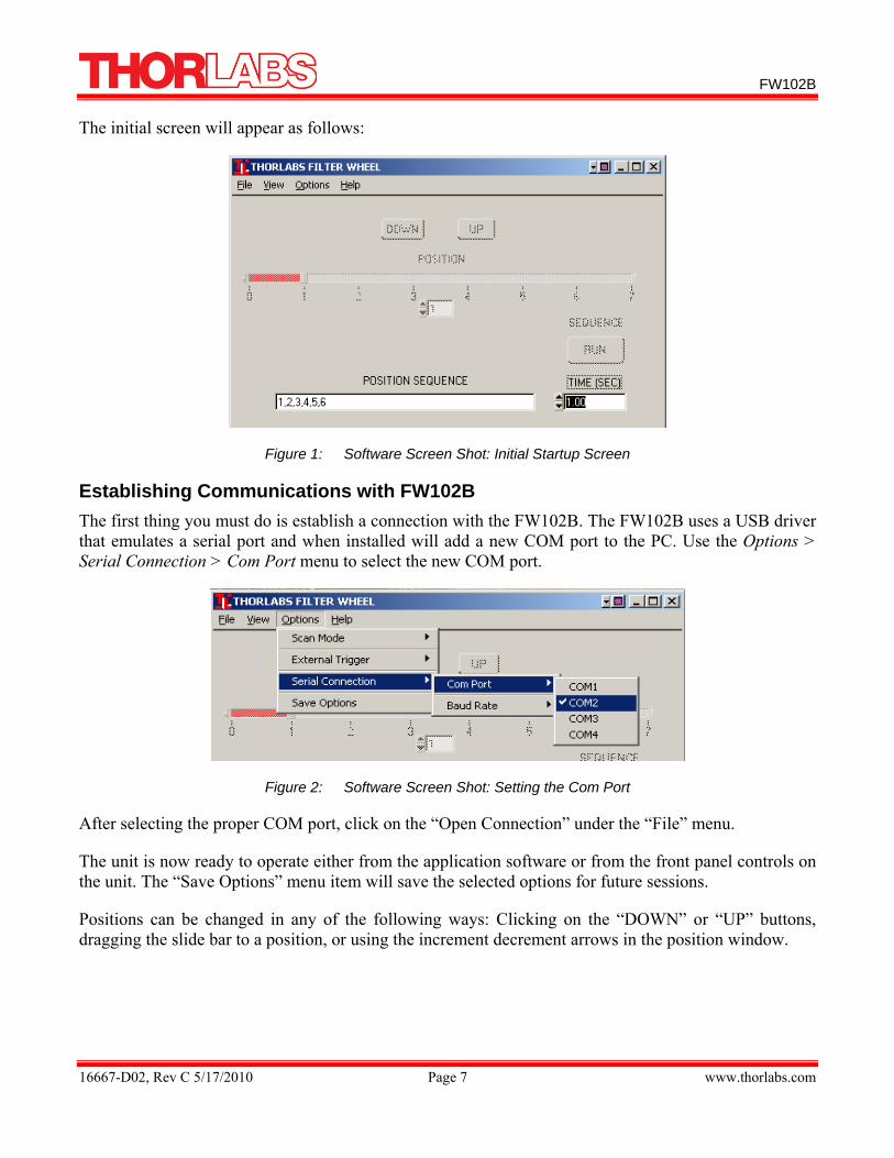
The initial screen will appear as follows:
Figure 1: Software Screen Shot: Initial Startup Screen
Establishing Communications with FW102B The first thing you must do is establish a connection with the FW102B. The FW102B uses a USB driver that emulates a serial port and when installed will add a new COM port to the PC. Use the Options > Serial Connection > Com Port menu to select the new COM port.
Figure 2: Software Screen Shot: Setting the Com Port
After selecting the proper COM port, click on the “Open Connection” under the “File” menu.
The unit is now ready to operate either from the application software or from the front panel controls on the unit. The “Save Options” menu item will save the selected options for future sessions.
Positions can be changed in any of the following ways: Clicking on the “DOWN” or “UP” buttons, dragging the slide bar to a position, or using the increment decrement arrows in the position window.

FW102B
16667-D02, Rev C 5/17/2010 Page 8 www.thorlabs.com
Figure 3: Software Screen Shot: Changing the Filter Position
Programmed Sequence Operation (Scan Mode) The application software also contains the capability to control filter wheel in a programmed sequence.
To operate in this mode, enter the filter number(s) in the desired sequence in the POSITION SEQUENCE box. A comma should separate each entry. The TIME (SEC) box sets the desired repetition rate of the filter changes. It is not recommended to go below 0.5 seconds in this mode of operation.
The programmed sequence may be set to run a single event or in a continuous mode. This is selected in the Options->Scan Mode. The sequence will begin by clicking on the RUN button.
Help The HELP menu contains a synopsis of the Command Line language for those who need to generate a scripting program to control the FW102B.
2.4. Command Line Interface The FW102B may also be controlled by a command line language through the USB port. This is offered to enable operation through a terminal interface or for those who may want to write their own program to control the wheel. The command language is described below. Prior to running the command line interface the unit should be powered and a USB cable should be connected between the FW102B and the host. The terminal emulator should be set as follows:
• Baud Rate = 115.2K Bits Per Second • Data Bits = 8 • Parity = None • Stop Bits = 1 • Flow Control = None
FW102B
16667-D02, Rev C 5/17/2010 Page 9 www.thorlabs.com
If the connection is correct you will see the following after pressing the Enter key.
Command error CMD_NOT_DEFINED
Followed immediately by the prompt:
>
The basic structure of the interface is a keyword followed by either an equals sign “=” or a question mark “?”. The “=” or “?” will determine if the string is a command or a query. All strings (commands and queries) must be terminated by a carriage return (CR) or pressing the ENTER key on the computer.
The command structure is as follows:
Keyword = argument (CR)
Where “keyword” defines the function and “argument” is a numerical value followed by a carriage return (CR). See listing below.
The query structure is a follows:
Keyword? (CR)
The “keyword” defines the function and the question mark (?) indicates a query. The string is terminated with a carriage return (CR). See listing below. There are a few exceptions to this which are noted below, also noted are unique shortcut keys.
The prompt symbol “>” will appear on power up and after a command is accepted by the FW102B indicating it is ready to receive another command line.

FW102B
16667-D02, Rev C 5/17/2010 Page 10 www.thorlabs.com
Keywords (Commands and Queries) The following list shows all of the available commands and queries, and summarizes their functions:
Command Syntax* Description Get ID *idn? Returns the model number and firmware version.
Set Position pos=(n) Where (n) equals a filter position number of 1 through 6.
Get Position- pos? Where (n) equals the location of the filter selection (1 through 6).
Set Trigger Mode trig=0 Sets the external trigger to the input mode.
trig=1 Sets the external trigger to the output mode.
Get Trigger Mode trig? Returns the trigger mode.
Set Sensor Mode sensors=0 Sensors turn off when wheel is idol to eliminate stray light
sensors=1 Sensors remain active
Get Sensor Mode sensors? Returns the sensor mode
Save Settings save This will save the current baud rate and trigger mode as the default on power up.
* All commands and queries are in lower case letters.
If the keyword, format, or argument are incorrect or out of range the unit will return an error string.
In addition to the above commands there is also special functionality added to the arrow keys of the computer’s keyboard.
• Up Arrow Key – Increments the filter position by 1. • Down Arrow Key – Decrements the filter position by 1.
Software Installation Insert the FW102B CD into the CD ROM drive. Installation instructions are contained in the Readme.txt file in the FW102B subdirectory of the CD ROM.
Minimum PC Requirements The application program requires a minimum of a Pentium class machine running Windows 98, 2000, NT or XP.

FW102B
16667-D02, Rev C 5/17/2010 Page 11 www.thorlabs.com
Part 3. Specifications
3.1. Performance
Parameter Min Typical Max Access Time Adjacent Locations - 300 ms -
Access Time Any Other Location - 600 ms -
Accuracy/Repeatability ±1° < ±2°
3.2. Electrical
Parameter Min Typical Max BNC Input Trigger
Max Rate – – 0.5 pulses/sec
Minimum Pulse width 1.0 ms – –
BNC Input Trigger*
Input High 3.3 V 4.5 V 5.3 V
Input Low -0.3 V 0.0 V 1.0 V
BNC Output Trigger -
Output Pulse Width 9.0 ms 10.0 ms 11.0 ms
Output High† 2.5 V (1K Ω) 3.3 V (1.95 K Ω) 5.0 (Hi Z)
Output Low† 0.0 V 0.0 V 1.0 V
Power @ DC Input. @ 1 A +4.75 VDC +5 VDC +5.25 VDC
Operating Temperature 0°C – 60°C
* The BNC input trigger is an active low input. The input has an internal 1 KΩ input resistor. Grounding the center conductor of the jack will activate the trigger.
† When configured as an output, the unit output driver is configured in series with a 1 KΩ resistor.
FW102B
16667-D02, Rev C 5/17/2010 Page 12 www.thorlabs.com
3.3. Physical Characteristics and Interface
Parameter Description Trigger Jack BNC female
Power Jack Male 2.1MM
USB Connector Mini B
Mounting 1/4"-20, #8-32, M6, M4 or SM1 Thread
Filter Diameter* 1.0" (25.4 mm)
Max Planar Filter Width 0.25" (6.35 mm)
Dimensions (L x W x H) 5.44" x 1.85" x 4.39" (138 mm x 47 mm x 112 mm)
Weight (Without Power Supply)
12 oz (340 g)
* 25 mm filters may require an additional SM1RR-CT retaining ring to secure the filter on each side of the filter mounting hole.
3.4. Drawings and Illustrations
Figure 4: Mechanical Drawing, Sides

FW102B
16667-D02, Rev C 5/17/2010 Page 13 www.thorlabs.com
Figure 5: Mechanical Drawing, Top and Bottom
Figure 6: Mechanical Drawing, Front

FW102B
16667-D02, Rev C 5/17/2010 Page 14 www.thorlabs.com
3.5. Supplied Equipment The FW102B comes with the following.
Qty Description 1 Controller with Filter Housing
1 FW102B Filter Wheel
1 5 Volt DC Converter
1 Power Cord
1 Hex Key Tool (5/64")
2 SM1CP2 End Caps
6 SM1RR Retaining Rings

FW102B
16667-D02, Rev C 5/17/2010 Page 15 www.thorlabs.com
Part 4. Troubleshooting
Problem Solution Filter wheel fails to change aperture position when A/B switch changed.
The wheel will not change positions until either the up or down filter position selector is pushed. Try setting the A/B switch to the desired aperture setting and then hitting the up arrow key on the top of the filter box.
Filter wheel will not set to the correct position or jitters back and forth around position before settling.
Try removing the filter holder from the assembly and cleaning the flat surface with a paper towel or buffing cloth to remove any shiny surfaces.
The wheel keeps spinning and can’t locate the proper filter position selected.
This problem can generally be fixed by turning the unit off, unplugging the power cord, and removing the USB cable (if attached). Then plugging in the power cord, turning the unit on, and plugging in the UBS cable.
The filter wheel jumps past the position desired or goes to the wrong position.
Dust or debris can sometimes get into the filter where housing and block the sensors. Remove the filter wheel tray and try using compressed air to clear away any contaminates.
The devices turns off a few seconds after being turned on. Something maybe caught in the wheel preventing it from turning. Turn the unit off and unplug the power cord. Try removing the filter wheel cover and filter tray and cleaning out area.
If you have any other technical problems, or cannot resolve the above issues, please call your local technical support center for assistance.

FW102B
16667-D02, Rev C 5/17/2010 Page 16 www.thorlabs.com
Part 5. Regulatory As required by the WEEE (Waste Electrical and Electronic Equipment Directive) of the European Community and the corresponding national laws, Thorlabs offers all end users in the EC the possibility to return “end of life” units without incurring disposal charges.
• This offer is valid for Thorlabs electrical and electronic equipment: • Sold after August 13th 2005 • Marked correspondingly with the crossed out “wheelie bin” logo (see) • Sold to a company or institute within the EC • Currently owned by a company or institute within the EC • Still complete, not disassembled and not contaminated
As the WEEE directive applies to self contained operational electrical and electronic products, this end of life take back service does not refer to other Thorlabs products, such as:
• Pure OEM products, that means assemblies to be built into a unit by the user (e. g. OEM laser driver cards)
• Components • Mechanics and optics • Left over parts of units disassembled by the user (PCB’s, housings etc.).
If you wish to return a Thorlabs unit for waste recovery, please contact Thorlabs or your nearest dealer for further information.
5.1. Waste Treatment is Your Own Responsibility If you do not return an “end of life” unit to Thorlabs, you must hand it to a company specialized in waste recovery. Do not dispose of the unit in a litter bin or at a public waste disposal site.
5.2. Ecological Background It is well known that WEEE pollutes the environment by releasing toxic products during decomposition. The aim of the European RoHS directive is to reduce the content of toxic substances in electronic products in the future.
The intent of the WEEE directive is to enforce the recycling of WEEE. A controlled recycling of end of live products will thereby avoid negative impacts on the environment.
Wheelie Bin Logo

FW102B
16667-D02, Rev C 5/17/2010 Page 17 www.thorlabs.com
Part 6. Thorlabs, Inc Worldwide Contacts For technical support or sales inquiries, please visit us at www.thorlabs.com/contact for our most up-to-date contact information.
USA, Canada, and South America Thorlabs, Inc. [email protected] [email protected]
Europe Thorlabs GmbH [email protected]
France Thorlabs SAS [email protected]
Japan Thorlabs Japan, Inc. [email protected]
UK and Ireland Thorlabs Ltd. [email protected] [email protected]
Scandinavia Thorlabs Sweden AB [email protected]
Brazil Thorlabs Vendas de Fotônicos Ltda. [email protected]
China Thorlabs China [email protected]

www.thorlabs.com