fx3u-cf-adp user's manual - mitsubishi electric1) before installation, operation, ... • do...
TRANSCRIPT
FX3U-CF-ADP
USER'S MANUAL

Before installation, operation, maintenance or inspection of this product, thoroughly read through andunderstand this manual and all of the associated manuals. Also, take care to handle the module properly andsafely.
This manual classifies the safety precautions into two categories: and .
Depending on the circumstances, procedures indicated by may also cause severe injury.It is important to follow all precautions for personal safety.Store this manual in a safe place so that it can be taken out and read whenever necessary. Always forward itto the end user.
1. DESIGN PRECAUTIONS
Indicates that incorrect handling may cause hazardous conditions, resulting in death or severeinjury.
Indicates that incorrect handling may cause hazardous conditions, resulting in medium or slightpersonal injury or physical damage.
Reference
• Make sure to include the following safety circuits outside the PLC to ensure safe system operation even duringexternal power supply problems or PLC failure.Otherwise, malfunctions may cause serious accidents.1) Above all, the following components should be included: an emergency stop circuit, a protection circuit, an
interlock circuit for opposite movements (such as normal vs. reverse rotation), and an interlock circuit (to preventdamage to the equipment at the upper and lower positioning limits).
2) Note that when the PLC main unit detects an error during self diagnosis, such as a watchdog timer error, alloutputs are turned off. Also, when an error that cannot be detected by the PLC main unit occurs in an input/output control block, output control may be disabled.External circuits and mechanisms should be designed to ensure safe machinery operation in such cases.
1528
Reference
• Observe the following items. Failure to do so may cause incorrect data-writing through noise to the PLC and resultin PLC failure, machine damage or other accident.1) Do not bundle the control line together with or lay it close to the main circuit or power line. As a guideline, lay the
control line at least 100mm (3.94") or more away from the main circuit or power line.Noise may cause malfunctions.
2) Ground the shield wire or shield of a shielded cable. Do not use common grounding with heavy electricalsystems
• During access (ACCESS LED is lit or flickering) to CompactFlashTM card, do not remove the CompactFlashTM cardor power off the FX3U-CF-ADP.
Failure to do so may cause CompactFlashTM card failures or malfunctions.
• If the power is turned OFF while the CompactFlashTM card is being accessed (ACCESS LED is lit or flickering), the
buffered data is erased. Also files or CompactFlashTM card itself may be damaged. Do not turn the power OFFwhile the ACCESS LED is lit or flickering.
• Do not apply excessive pressure to the power supply cable or power supply connector. Excessive pressure may cause damage or error.
1528
Safety Precautions(Read these precautions before use.)
(1)
Safety Precautions(Read these precautions before use.)
2. INSTALLATION PRECAUTIONS
3. WIRING PRECAUTIONS
Reference
• Make sure to shut down all phases of the power supply externally before installing the FX3U-CF-ADP.Failure to do so may cause electric shock or damage to the product.
22100
Reference
• Use the product within the generic environment specifications described in PLC main unit manual (HardwareEdition). Never use the product in areas with excessive dust, oily smoke, conductive dusts, corrosive gas (salt air,Cl2, H2S, SO2, or NO2), flammable gas, vibration or impacts, or expose it to high temperature, condensation, orrain and wind. If the product is used in such conditions, electric shock, fire, malfunctions, deterioration or damagemay occur.
• Do not touch the conductive parts of the product directly.Doing so may cause device failures or malfunctions.
• Install the product securely using a DIN rail or mounting screws.• Install the product on a flat surface.
If the mounting surface is rough, undue force will be applied to the PC board, thereby causing nonconformities.• When drilling screw holes or wiring, make sure that cutting and wiring debris do not enter the ventilation slits.
Failure to do so may cause fire, equipment failures or malfunctions.• Be sure to remove the dust proof sheet from the PLC's ventilation port when installation work is completed.
Failure to do so may cause fire, equipment failures or malfunctions.• Connect the FX3U-CF-ADP securely to special adapter connector.
Loose connections may cause malfunctions.• Connect the power connector of the power supply cable securely to the CF-ADP power supply connector.
Loose connections may cause malfunctions.
• When inserting a CompactFlashTM card into the FX3U-CF-ADP, push it into the CF card slot until the EJECT buttonpops out.Loose connections may cause malfunctions.
• Before inserting/removing a CompactFlashTM card into/from the FX3U-CF-ADP, set the CF card ACCESS switch toOFF and confirm that the BUFFER LED and ACCESS LED are both OFF.
Failure to do so may corrupt data within the CompactFlashTM card.
• When removing a CompactFlashTM card from the FX3U-CF-ADP, make sure to support the CompactFlashTM cardby hand, as it may pop out.
Failure to do so may cause the CompactFlashTM card to fall from the FX3U-CF-ADP and break.• Turn off the power to the PLC before attaching or detaching the following devices.
Failure to do so may cause device failures or malfunctions.- Peripheral devices, display modules, expansion boards and special adapters- I/O extension units/blocks, FX Series terminal block and the special function units/blocks- Battery and memory cassette
22100
Reference
• Make sure to cut off all phases of the power supply externally before attempting wiring work.Failure to do so may cause electric shock or damage to the product.
28100
Reference
• Connect the DC power supply wiring to the dedicated terminal described in this manual.If an AC power supply is connected to a DC input/output terminal or DC power supply terminal, the PLC will burnout.
• Connect the DC power supply wiring to the dedicated connector described in this manual.If an AC power supply is connected to a DC power supply connector, the PLC will burn out.
• When drilling screw holes or wiring, make sure that cutting and wiring debris do not enter the ventilation slits.Failure to do so may cause fire, equipment failures or malfunctions.
28100
(2)
Safety Precautions(Read these precautions before use.)
4. STARTUP AND MAINTENANCE PRECAUTIONS
5. DISPOSAL PRECAUTIONS
6. TRANSPORTATION AND STORAGE PRECAUTIONS
Reference
• Make sure to connect the battery for memory backup correctly. Do not charge, disassemble, heat, short-circuit, orexpose the battery to fire.Doing so may rupture or ignite it.
• Do not touch any terminal while the PLC's power is on.Doing so may cause electric shock or malfunctions.
• Before modifying or disrupting the program in operation or running the PLC, carefully read through this manual andthe associated manuals and ensure the safety of the operation. An operation error may damage the machinery or cause accidents.
2882
101
Reference
• Do not disassemble or modify the PLC.Doing so may cause fire, equipment failures, or malfunctions.For repair, contact your local Mitsubishi Electric representative.
• Turn off the power to the PLC before attaching or detaching the following devices.Failure to do so may cause device failures or malfunctions.- Peripheral devices, display modules, expansion boards and special adapters- I/O extension units/blocks, FX Series terminal block and the special function units/blocks- Battery and memory cassette
2982
101
Reference
• Please contact a certified electronic waste disposal company for the environmentally safe recycling and disposal ofyour device.
15
Reference
• The PLC is a precision instrument. During transportation, avoid impacts larger than those specified in the generalspecifications of the PLC main unit manual by using dedicated packaging boxes and shock-absorbing palettes.Failure to do so may cause failures in the PLC.After transportation, verify operation of the PLC and check for damage of the mounting part, etc.
15
(3)

(4)
FX3U-CF-ADP User's Manual
FX3U-CF-ADP
User's Manual
Foreword
This manual describes the FX3U-CF-ADP CF card special adapter and should be read and understood before attempting to install the hardware.Store this manual in a safe place so that you can take it out and read it whenever necessary. Always forward it to the end user.
© 2009 MITSUBISHI ELECTRIC CORPORATION
Manual number JY997D35401
Manual revision E
Date 4/2015
This manual confers no industrial property rights or any rights of any other kind, nor does it confer any patent licenses. MitsubishiElectric Corporation cannot be held responsible for any problems involving industrial property rights which may occur as a result ofusing the contents noted in this manual.
1
FX3U-CF-ADP User's Manual
Outline Precautions
• This manual provides information for the use of the FX3U-CF-ADP CF card special adapter.The manual has been written to be used by trained and competent personnel. The definition of such a person or persons is as follows;
1) Any engineer who is responsible for the planning, design and construction of automatic equipment usingthe product associated with this manual should be of a competent nature, trained and qualified to thelocal and national standards required to fulfill that role. These engineers should be fully aware of allaspects of safety with aspects regarding to automated equipment.
2) Any commissioning or maintenance engineer must be of a competent nature, trained and qualified to thelocal and national standards required to fulfill the job. These engineers should also be trained in the useand maintenance of the completed product. This includes being familiar with all associated manuals anddocumentation for the product. All maintenance should be carried out in accordance with establishedsafety practices.
3) All operators of the completed equipment should be trained to use that product in a safe and coordinatedmanner in compliance with established safety practices. The operators should also be familiar withdocumentation that is connected with the actual operation of the completed equipment.
Note: the term 'completed equipment' refers to a third party constructed device that contains or uses the product associated with this manual.
• This product has been manufactured as a general-purpose part for general industries, and has not been designed or manufactured to be incorporated in a device or system used in purposes related to human life.
• Before using the product for special purposes such as nuclear power, electric power, aerospace, medicine or passenger movement vehicles, consult with Mitsubishi Electric.
• This product has been manufactured under strict quality control. However when installing the product where major accidents or losses could occur if the product fails, install appropriate backup or failsafe functions into the system.
• When combining this product with other products, please confirm the standards and codes of regulation to which the user should follow. Moreover, please confirm the compatibility of this product with the system, machines, and apparatuses to be used.
• If there is doubt at any stage during installation of the product, always consult a professional electrical engineer who is qualified and trained in the local and national standards. If there is doubt about the operation or use, please consult your local Mitsubishi Electric representative.
• Since the examples within this manual, technical bulletin, catalog, etc. are used as reference; please use it after confirming the function and safety of the equipment and system. Mitsubishi Electric will not accept responsibility for actual use of the product based on these illustrative examples.
• The content, specification etc. of this manual may be changed for improvement without notice.• The information in this manual has been carefully checked and is believed to be accurate; however, if you
notice any doubtful point, error, etc., please contact your local Mitsubishi Electric representative.
Registration
• CompactFlash is a trademark of SanDisk Corporation in the United States and other countries.
• MODBUS® is a registered trademark of Schneider Electric SA.• The company name and the product name to be described in this manual are the registered trademarks or
trademarks of each company.
2
FX3U-CF-ADP User's Manual Table of Contents
Table of ContentsSAFETY PRECAUTIONS .................................................................................................. (1)Standards................................................................................................................................... 7
Certification of UL, cUL standards ....................................................................................................... 7 Compliance with EC directive (CE Marking) ........................................................................................ 7
Associated Manuals.................................................................................................................. 9Generic Names and Abbreviations Used in the Manual ...................................................... 10Reading the Manual ................................................................................................................ 12
1. Introduction 13
1.1 Outline........................................................................................................................................... 131.2 External Dimensions and Part Names .......................................................................................... 131.3 Power and status LEDs................................................................................................................. 14
2. Specification 15
2.1 General specifications................................................................................................................... 162.2 Power supply specification............................................................................................................ 162.3 Performance specification............................................................................................................. 162.4 CF card ACCESS switch specification.......................................................................................... 17
2.5 CompactFlashTM card specification .............................................................................................. 17
2.6 Applicable CompactFlashTM card ................................................................................................. 17
3. System Configuration 18
3.1 General configuration.................................................................................................................... 183.2 Applicable PLC.............................................................................................................................. 19
3.2.1 Connectable PLC .......................................................................................................................... 193.2.2 Applicable versions of the programming tool................................................................................. 19
3.3 Connection with PLC..................................................................................................................... 193.4 Assignment of channels ................................................................................................................ 20
4. Installation 22
4.1 CF-ADP Connection...................................................................................................................... 234.2 DIN rail mounting .......................................................................................................................... 244.3 Direct mounting ............................................................................................................................. 254.4 Inserting and Removal Procedures............................................................................................... 26
4.4.1 Inserting the CompactFlashTM card .............................................................................................. 26
4.4.2 Removing the CompactFlashTM card ............................................................................................ 27
3
FX3U-CF-ADP User's Manual Table of Contents
5. Wiring 28
5.1 Which Power Supply Cable to Use ............................................................................................... 295.1.1 Power supply cable ....................................................................................................................... 29
5.2 Power Supply Wiring..................................................................................................................... 305.2.1 Power supply wiring....................................................................................................................... 30
5.3 Grounding ..................................................................................................................................... 305.4 Power OFF procedure................................................................................................................... 31
5.4.1 Power OFF procedure using the CF card ACCESS switch........................................................... 315.4.2 Power OFF procedure using the applied instruction for the CF-ADP............................................ 315.4.3 Caution on power OFF .................................................................................................................. 31
5.5 Connection of the power supply cable .......................................................................................... 325.5.1 Connection/removal of the power supply cable............................................................................. 32
6. Functions 33
6.1 Details of functions........................................................................................................................ 336.2 Status information ......................................................................................................................... 34
7. Before Programming 35
7.1 File format available in the CF-ADP.............................................................................................. 357.1.1 Files created by the CF-ADP......................................................................................................... 357.1.2 Files created by the user ............................................................................................................... 367.1.3 Characters available in files........................................................................................................... 377.1.4 Data size calculation...................................................................................................................... 387.1.5 Data writing destination ................................................................................................................. 407.1.6 File ID ............................................................................................................................................ 417.1.7 FIFO file......................................................................................................................................... 42
7.2 Directory structure......................................................................................................................... 437.3 Date/time setting ........................................................................................................................... 437.4 General Rules for Applied Instructions.......................................................................................... 44
7.4.1 Expression and operation type of applied instructions .................................................................. 447.4.2 Programming using "Instruction execution complete" flag and
"Instruction execution abnormal end" flag ................................................................................ 45
8. CF-ADP Applied Instructions Explanation 47
8.1 CF-ADP Instructions types............................................................................................................ 478.2 Common Items in CF-ADP Instructions ........................................................................................ 47
8.2.1 Function and operation.................................................................................................................. 478.2.2 Cautions on programming ............................................................................................................. 48
8.3 FNC 300 - FLCRT / File create•check .......................................................................................... 498.3.1 Detailed explanation of setting data .............................................................................................. 50
8.4 FNC 301 - FLDEL / File delete•CF card format ............................................................................ 528.4.1 Detailed explanation of setting data .............................................................................................. 53
8.5 FNC 302 - FLWR / Data write ....................................................................................................... 558.5.1 Detailed explanation of setting data .............................................................................................. 578.5.2 Writing data of same type.............................................................................................................. 588.5.3 Writing data of different types........................................................................................................ 62
8.6 FNC 303 - FLRD / Data read ........................................................................................................ 698.6.1 Detailed explanation of setting data .............................................................................................. 708.6.2 Reading data of the same type from a file..................................................................................... 718.6.3 Reading data of different types from a file..................................................................................... 72
8.7 FNC 304 - FLCMD / FX3U-CF-ADP command ............................................................................. 758.7.1 Detailed explanation of setting data .............................................................................................. 76
4
FX3U-CF-ADP User's Manual Table of Contents
8.8 FNC 305 - FLSTRD / FX3U-CF-ADP status read ......................................................................... 778.8.1 Detailed explanation of setting data .............................................................................................. 78
8.9 Contents of Related Devices......................................................................................................... 81
9. Program Examples 82
9.1 System Configuration.................................................................................................................... 829.2 Program Example 1 ...................................................................................................................... 83
9.2.1 Operation details ........................................................................................................................... 839.2.2 Example of a 32-bit decimal type file in "csv" format after writing ................................................. 839.2.3 Device Assignments ...................................................................................................................... 849.2.4 Sequence Program........................................................................................................................ 85
9.3 Program Example 2 ...................................................................................................................... 909.3.1 Operation details ........................................................................................................................... 909.3.2 Example of a mixed type file in "csv" format after writing .............................................................. 909.3.3 Device Assignments ...................................................................................................................... 909.3.4 Sequence Program........................................................................................................................ 92
9.4 Program Example 3 ...................................................................................................................... 989.4.1 Operation details ........................................................................................................................... 989.4.2 Device Assignments ...................................................................................................................... 989.4.3 Sequence Program........................................................................................................................ 99
10. Troubleshooting 100
10.1 Troubleshooting procedure ....................................................................................................... 10210.1.1 LED status check....................................................................................................................... 10210.1.2 Troubleshooting by error code................................................................................................... 10210.1.3 Error Code List and Action ........................................................................................................ 103
10.2 Diagnostics on the PLC Main Unit ............................................................................................ 10810.2.1 POWER(POW) LED [on/flashing/off]......................................................................................... 10810.2.2 BATT(BAT) LED [on/off] ............................................................................................................ 10810.2.3 ERROR(ERR) LED [on/flashing/off] .......................................................................................... 109
Appendix A: Related Devices 110
Appendix A-1 Related Device List ............................................................................................ 110Appendix A-2 Details of related devices ................................................................................... 111
Appendix A-2-1 Instruction execution complete [M8029] ..................................................................... 111Appendix A-2-2 Instruction execution abnormal end [M8329].............................................................. 111Appendix A-2-3 CF-ADP instruction executing [M8402, M8422].......................................................... 111Appendix A-2-4 CF-ADP unit ready [M8404, M8424]........................................................................... 111Appendix A-2-5 CF card mount status [M8405, M8425] ...................................................................... 112Appendix A-2-6 CF-ADP status renewal stop [M8410, M8430] ........................................................... 112Appendix A-2-7 CF-ADP instruction error [M8418, M8438] ................................................................. 112Appendix A-2-8 CF-ADP status [D8406, D8426].................................................................................. 112Appendix A-2-9 CF-ADP version [D8408, D8428]................................................................................ 112Appendix A-2-10 Step number of an instruction for the CF-ADP where an error has occurred
[D8415, D8414][D8435, D8434].............................................................................. 113Appendix A-2-11 Error code for CF-ADP instructions [D8418, D8438] ................................................ 113Appendix A-2-12 Operation mode display [D8419, D8439].................................................................. 113
5

FX3U-CF-ADP User's Manual Table of Contents
Appendix B: Version Information 115
Appendix B-1 Version information ............................................................................................ 115Appendix B-1-1 Version check method ................................................................................................ 115Appendix B-1-2 Version upgrade history.............................................................................................. 115
Warranty................................................................................................................................. 117Revised History ..................................................................................................................... 118
6
StandardsFX3U-CF-ADP User's Manual
Standards
Certification of UL, cUL standards
FX3U-CF-ADP units comply with the UL standards (UL, cUL).
UL, cUL File number :E95239
Regarding the standards that comply with the main unit, please refer to either the FX series product catalog orconsult with your nearest Mitsubishi product provider.
Compliance with EC directive (CE Marking)
This document does not guarantee that a mechanical system including this product will comply with thefollowing standards.Compliance to EMC directive and LVD directive for the entire mechanical module should be checked by theuser / manufacturer. For more information please consult with your nearest Mitsubishi product provider.Regarding the standards that comply with the main unit, please refer to either the FX series product catalog orconsult with your nearest Mitsubishi product provider.
Attention
• This product is designed for use in industrial applications.
Note
• Authorized Representative in the European Community: Mitsubishi Electric Europe B.V.Gothaer Str. 8, 40880 Ratingen, Germany
Requirement for Compliance with EMC directive
The following products have shown compliance through direct testing (of the identified standards below) and design analysis (through the creation of a technical construction file) to the European Directive for Electromagnetic Compatibility (2004/108/EC) when used as directed by the appropriate documentation.
Type: Programmable Controller (Open Type Equipment)Models: MELSEC FX3U series manufactured from June 1st, 2009 FX3U-CF-ADP
Standard Remark
EN61131-2:2007Programmable controllers
- Equipment requirements and tests
Compliance with all relevant aspects of the standard.EMI• Radiated Emission• Conducted EmissionEMS• Radiated electromagnetic field• Fast Transient burst• Electrostatic discharge• High-energy surge• Voltage drops and interruptions• Conducted RF• Power frequency magnetic field
7
StandardsFX3U-CF-ADP User's Manual
Caution to conform with EC Directives
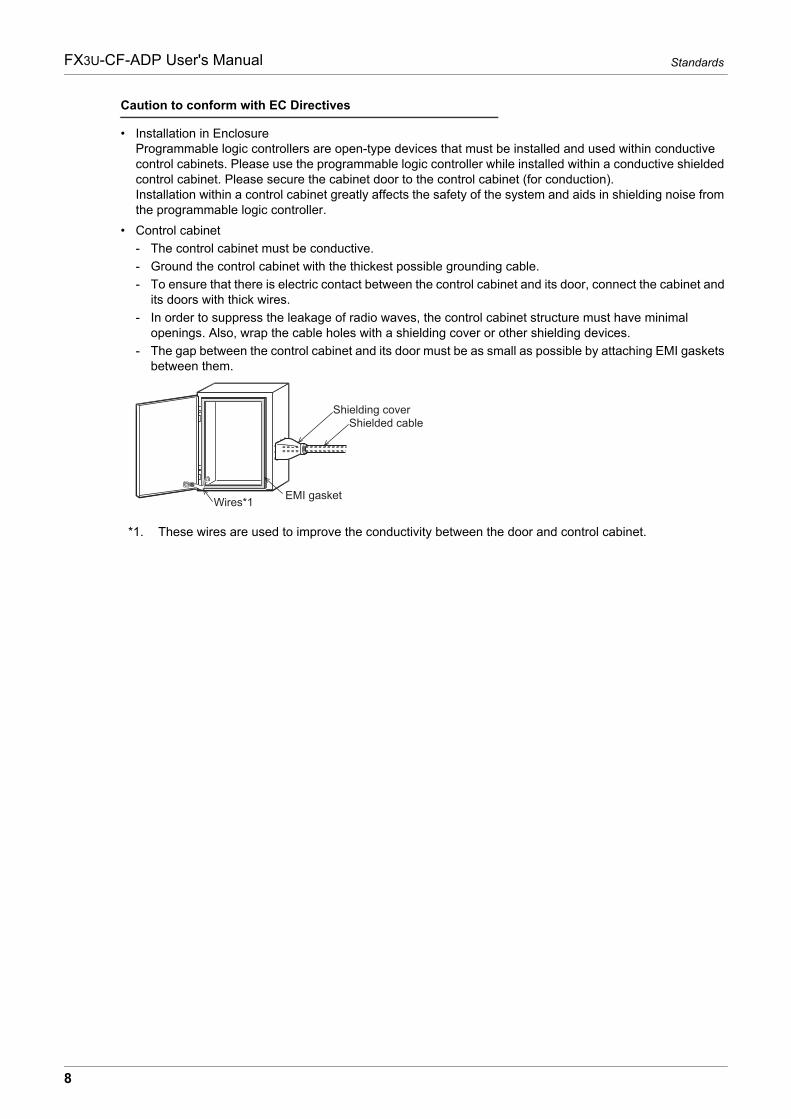
• Installation in EnclosureProgrammable logic controllers are open-type devices that must be installed and used within conductive control cabinets. Please use the programmable logic controller while installed within a conductive shielded control cabinet. Please secure the cabinet door to the control cabinet (for conduction).Installation within a control cabinet greatly affects the safety of the system and aids in shielding noise from the programmable logic controller.
• Control cabinet
- The control cabinet must be conductive.
- Ground the control cabinet with the thickest possible grounding cable.
- To ensure that there is electric contact between the control cabinet and its door, connect the cabinet and its doors with thick wires.
- In order to suppress the leakage of radio waves, the control cabinet structure must have minimal openings. Also, wrap the cable holes with a shielding cover or other shielding devices.
- The gap between the control cabinet and its door must be as small as possible by attaching EMI gaskets between them.
*1. These wires are used to improve the conductivity between the door and control cabinet.
Shielding coverShielded cable
Wires*1 EMI gasket
8
Associated ManualsFX3U-CF-ADP User's Manual
Associated Manuals
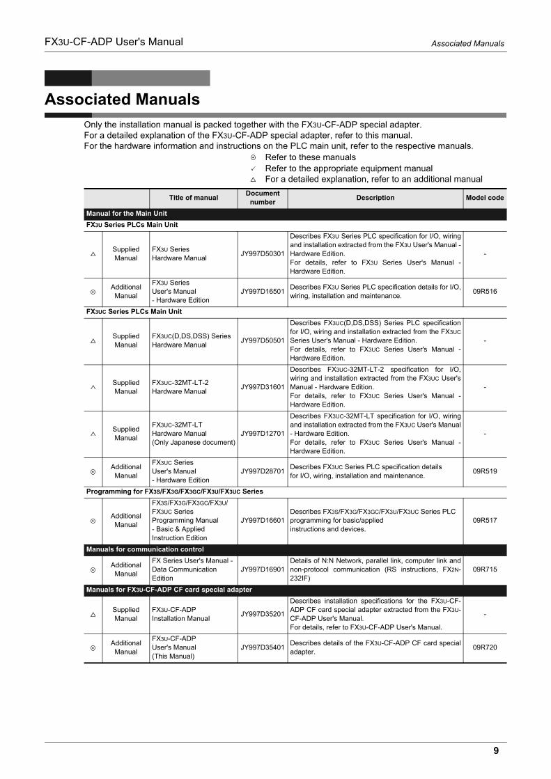
Only the installation manual is packed together with the FX3U-CF-ADP special adapter.For a detailed explanation of the FX3U-CF-ADP special adapter, refer to this manual.For the hardware information and instructions on the PLC main unit, refer to the respective manuals.
Refer to these manualsRefer to the appropriate equipment manualFor a detailed explanation, refer to an additional manual
Title of manualDocument
numberDescription Model code
Manual for the Main Unit
FX3U Series PLCs Main Unit
SuppliedManual
FX3U SeriesHardware Manual
JY997D50301
Describes FX3U Series PLC specification for I/O, wiringand installation extracted from the FX3U User's Manual -Hardware Edition.For details, refer to FX3U Series User's Manual -Hardware Edition.
-
AdditionalManual
FX3U SeriesUser's Manual- Hardware Edition
JY997D16501Describes FX3U Series PLC specification details for I/O,wiring, installation and maintenance.
09R516
FX3UC Series PLCs Main Unit
SuppliedManual
FX3UC(D,DS,DSS) SeriesHardware Manual
JY997D50501
Describes FX3UC(D,DS,DSS) Series PLC specificationfor I/O, wiring and installation extracted from the FX3UC
Series User's Manual - Hardware Edition.For details, refer to FX3UC Series User's Manual -Hardware Edition.
-
SuppliedManual
FX3UC-32MT-LT-2Hardware Manual
JY997D31601
Describes FX3UC-32MT-LT-2 specification for I/O,wiring and installation extracted from the FX3UC User'sManual - Hardware Edition.For details, refer to FX3UC Series User's Manual -Hardware Edition.
-
SuppliedManual
FX3UC-32MT-LTHardware Manual(Only Japanese document)
JY997D12701
Describes FX3UC-32MT-LT specification for I/O, wiringand installation extracted from the FX3UC User's Manual- Hardware Edition.For details, refer to FX3UC Series User's Manual -Hardware Edition.
-
AdditionalManual
FX3UC SeriesUser's Manual- Hardware Edition
JY997D28701Describes FX3UC Series PLC specification detailsfor I/O, wiring, installation and maintenance.
09R519
Programming for FX3S/FX3G/FX3GC/FX3U/FX3UC Series
AdditionalManual
FX3S/FX3G/FX3GC/FX3U/FX3UC SeriesProgramming Manual- Basic & AppliedInstruction Edition
JY997D16601Describes FX3S/FX3G/FX3GC/FX3U/FX3UC Series PLC programming for basic/applied instructions and devices.
09R517
Manuals for communication control
AdditionalManual
FX Series User's Manual -Data CommunicationEdition
JY997D16901Details of N:N Network, parallel link, computer link andnon-protocol communication (RS instructions, FX2N-232IF)
09R715
Manuals for FX3U-CF-ADP CF card special adapter
SuppliedManual
FX3U-CF-ADPInstallation Manual
JY997D35201
Describes installation specifications for the FX3U-CF-ADP CF card special adapter extracted from the FX3U-CF-ADP User's Manual.For details, refer to FX3U-CF-ADP User's Manual.
-
AdditionalManual
FX3U-CF-ADPUser's Manual(This Manual)
JY997D35401Describes details of the FX3U-CF-ADP CF card specialadapter.
09R720
9
Generic Names and Abbreviations Used in the ManualFX3U-CF-ADP User's Manual
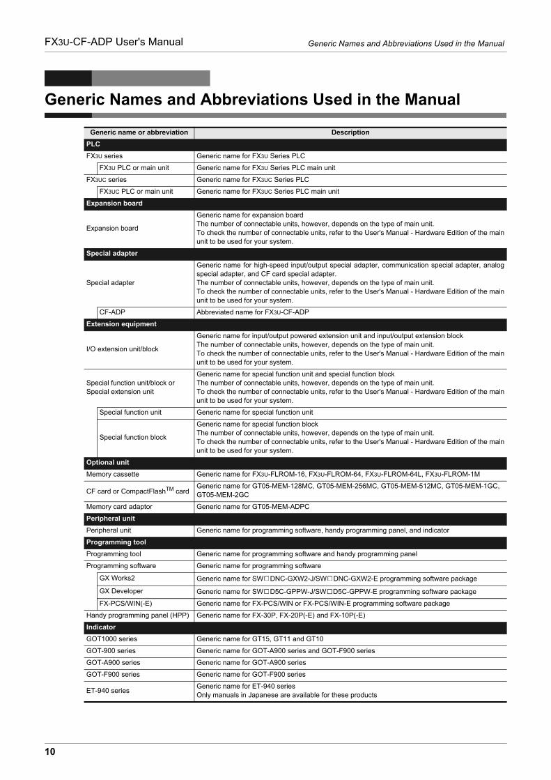
Generic Names and Abbreviations Used in the Manual
Generic name or abbreviation Description
PLC
FX3U series Generic name for FX3U Series PLC
FX3U PLC or main unit Generic name for FX3U Series PLC main unit
FX3UC series Generic name for FX3UC Series PLC
FX3UC PLC or main unit Generic name for FX3UC Series PLC main unit
Expansion board
Expansion board
Generic name for expansion boardThe number of connectable units, however, depends on the type of main unit.To check the number of connectable units, refer to the User's Manual - Hardware Edition of the mainunit to be used for your system.
Special adapter
Special adapter
Generic name for high-speed input/output special adapter, communication special adapter, analogspecial adapter, and CF card special adapter.The number of connectable units, however, depends on the type of main unit.To check the number of connectable units, refer to the User's Manual - Hardware Edition of the mainunit to be used for your system.
CF-ADP Abbreviated name for FX3U-CF-ADP
Extension equipment
I/O extension unit/block
Generic name for input/output powered extension unit and input/output extension blockThe number of connectable units, however, depends on the type of main unit.To check the number of connectable units, refer to the User's Manual - Hardware Edition of the mainunit to be used for your system.
Special function unit/block orSpecial extension unit
Generic name for special function unit and special function blockThe number of connectable units, however, depends on the type of main unit.To check the number of connectable units, refer to the User's Manual - Hardware Edition of the mainunit to be used for your system.
Special function unit Generic name for special function unit
Special function block
Generic name for special function blockThe number of connectable units, however, depends on the type of main unit.To check the number of connectable units, refer to the User's Manual - Hardware Edition of the mainunit to be used for your system.
Optional unit
Memory cassette Generic name for FX3U-FLROM-16, FX3U-FLROM-64, FX3U-FLROM-64L, FX3U-FLROM-1M
CF card or CompactFlashTM cardGeneric name for GT05-MEM-128MC, GT05-MEM-256MC, GT05-MEM-512MC, GT05-MEM-1GC, GT05-MEM-2GC
Memory card adaptor Generic name for GT05-MEM-ADPC
Peripheral unit
Peripheral unit Generic name for programming software, handy programming panel, and indicator
Programming tool
Programming tool Generic name for programming software and handy programming panel
Programming software Generic name for programming software
GX Works2 Generic name for SW DNC-GXW2-J/SW DNC-GXW2-E programming software package
GX Developer Generic name for SW D5C-GPPW-J/SW D5C-GPPW-E programming software package
FX-PCS/WIN(-E) Generic name for FX-PCS/WIN or FX-PCS/WIN-E programming software package
Handy programming panel (HPP) Generic name for FX-30P, FX-20P(-E) and FX-10P(-E)
Indicator
GOT1000 series Generic name for GT15, GT11 and GT10
GOT-900 series Generic name for GOT-A900 series and GOT-F900 series
GOT-A900 series Generic name for GOT-A900 series
GOT-F900 series Generic name for GOT-F900 series
ET-940 seriesGeneric name for ET-940 seriesOnly manuals in Japanese are available for these products
10

Generic Names and Abbreviations Used in the ManualFX3U-CF-ADP User's Manual
Generic name or abbreviation Description
Manual
FX3U Hardware Edition FX3U Series User's Manual - Hardware Edition
FX3UC Hardware Edition FX3UC Series User's Manual - Hardware Edition
Programming manual FX3S/FX3G/FX3GC/FX3U/FX3UC Series Programming Manual - Basic and Applied Instructions Edition
Communication control Edition FX Series User's Manual - Data Communication Edition
Analog control Edition FX3S/FX3G/FX3GC/FX3U/FX3UC Series User's Manual - Analog Control Edition
Positioning control Edition FX3S/FX3G/FX3GC/FX3U/FX3UC Series User's Manual - Positioning Control Edition
11
Reading the ManualFX3U-CF-ADP User's Manual
Reading the Manual
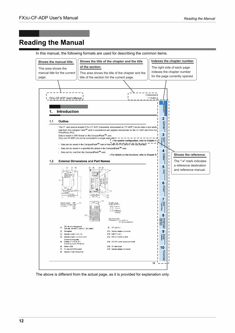
In this manual, the following formats are used for describing the common items.
The above is different from the actual page, as it is provided for explanation only.
This area shows the title of the chapter and the title of the section for the current page.
The right side of each page indexes the chapter number for the page currently opened.
This area shows the manual title for the current page.
The " " mark indicates a reference destination and reference manual.
Shows the reference.
Indexes the chapter number.Shows the title of the chapter and the title
of the section.Shows the manual title.
12
1 Introduction
1.1 OutlineFX3U-CF-ADP User's Manual
1
Introduction
2
Specification
3
System
C
onfiguration
4
Installation
5
Wiring
6
Functions
7
Before
Program
ming
8
CF-A
DP
Applied
Instructions E
xplanation
9
Program
E
xamples
10
Troubleshooting
1. Introduction
1.1 Outline
The CF card special adapter FX3U-CF-ADP (hereinafter abbreviated as "CF-ADP") stores data to and reads
data from the CompactFlashTM card in accordance with applied instructions for the CF-ADP sent from theFX3U/FX3UC PLC.
Data is stored in CSV format on the CompactFlashTM card. Only one CF-ADP unit can be connected to a single main unit.
For system configuration, refer to Chapter 3.
• Data can be saved in the CompactFlashTM card in files with the FIFO (first in, first out) function.
• Data can be saved in a specified file stored in the CompactFlashTM card.
• Data can be read from the CompactFlashTM card.For details on the functions, refer to Chapter 6.
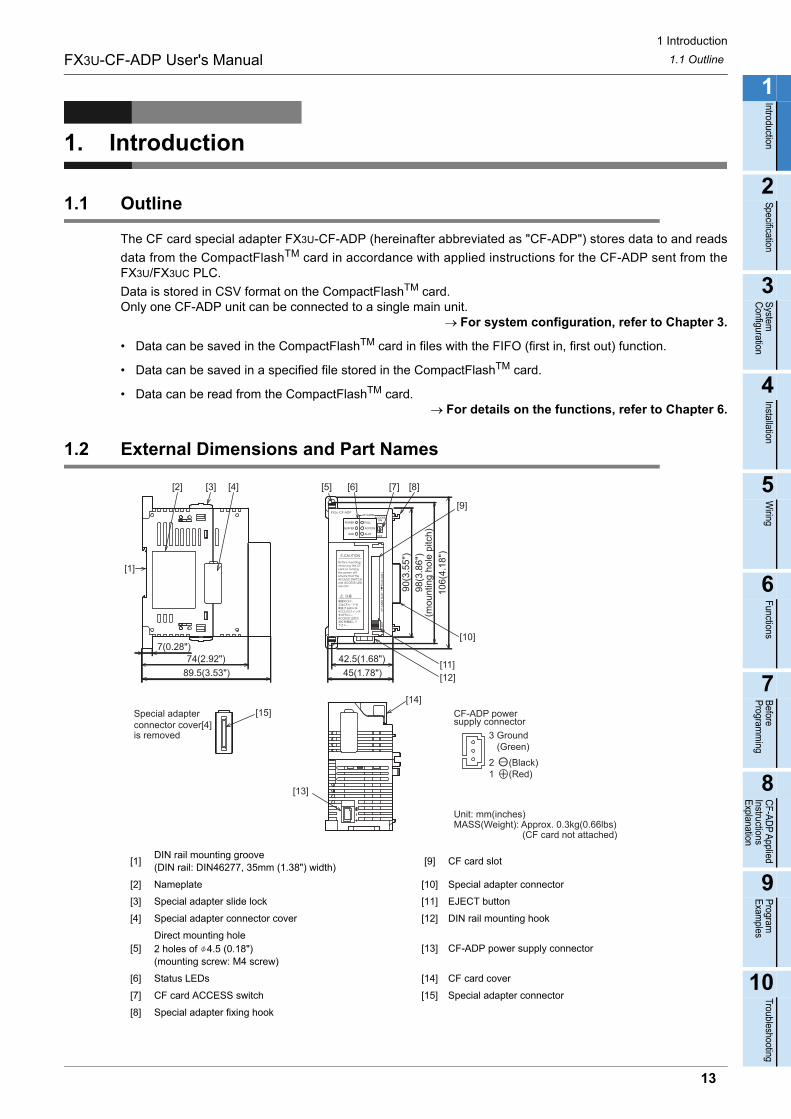
1.2 External Dimensions and Part Names
[1]DIN rail mounting groove(DIN rail: DIN46277, 35mm (1.38") width)
[9] CF card slot
[2] Nameplate [10] Special adapter connector
[3] Special adapter slide lock [11] EJECT button
[4] Special adapter connector cover [12] DIN rail mounting hook
[5] Direct mounting hole2 holes of 4.5 (0.18") (mounting screw: M4 screw)
[13] CF-ADP power supply connector
[6] Status LEDs [14] CF card cover
[7] CF card ACCESS switch [15] Special adapter connector
[8] Special adapter fixing hook
7(0.28")
89.5(3.53")
90(3
.55"
)98
(3.8
6")
(mou
ntin
g ho
le p
itch)
106(
4.18
")
45(1.78")
42.5(1.68")
[6][5] [8][7]
[10]
[12]
[3][2] [4]
Unit: mm(inches)MASS(Weight): Approx. 0.3kg(0.66lbs) (CF card not attached)
Special adapterconnector cover[4]is removed
[15]
[1]
74(2.92")
[14]
[13]
CF-ADP powersupply connector
3 Ground (Green)
21
(Black)(Red)
[9]
[11]
13
1 Introduction
1.3 Power and status LEDsFX3U-CF-ADP User's Manual
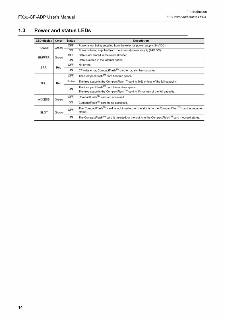
1.3 Power and status LEDs
LED display Color Status Description
POWER GreenOFF Power is not being supplied from the external power supply (24V DC).
ON Power is being supplied from the external power supply (24V DC).
BUFFER GreenOFF Data is not stored in the internal buffer.
ON Data is stored in the internal buffer.
ERR. RedOFF No errors.
ON CF write error, CompactFlashTM card error, etc. has occurred.
FULL Red
OFF The CompactFlashTM card has free space.
Flicker The free space in the CompactFlashTM card is 20% or less of the full capacity.
ONThe CompactFlashTM card has no free space.
The free space in the CompactFlashTM card is 1% or less of the full capacity.
ACCESS GreenOFF CompactFlashTM card not accessed.
ON CompactFlashTM card being accessed.
SLOT GreenOFF The CompactFlashTM card is not inserted, or the slot is in the CompactFlashTM card unmounted
status.
ON The CompactFlashTM card is inserted, or the slot is in the CompactFlashTM card mounted status.
14
2 Specification
FX3U-CF-ADP User's Manual
1
Introduction
2
Specification
3
System
C
onfiguration
4
Installation
5
Wiring
6
Functions
7
Before
Program
ming
8
CF-A
DP
Applied
Instructions E
xplanation
9
Program
E
xamples
10
Troubleshooting
2. Specification
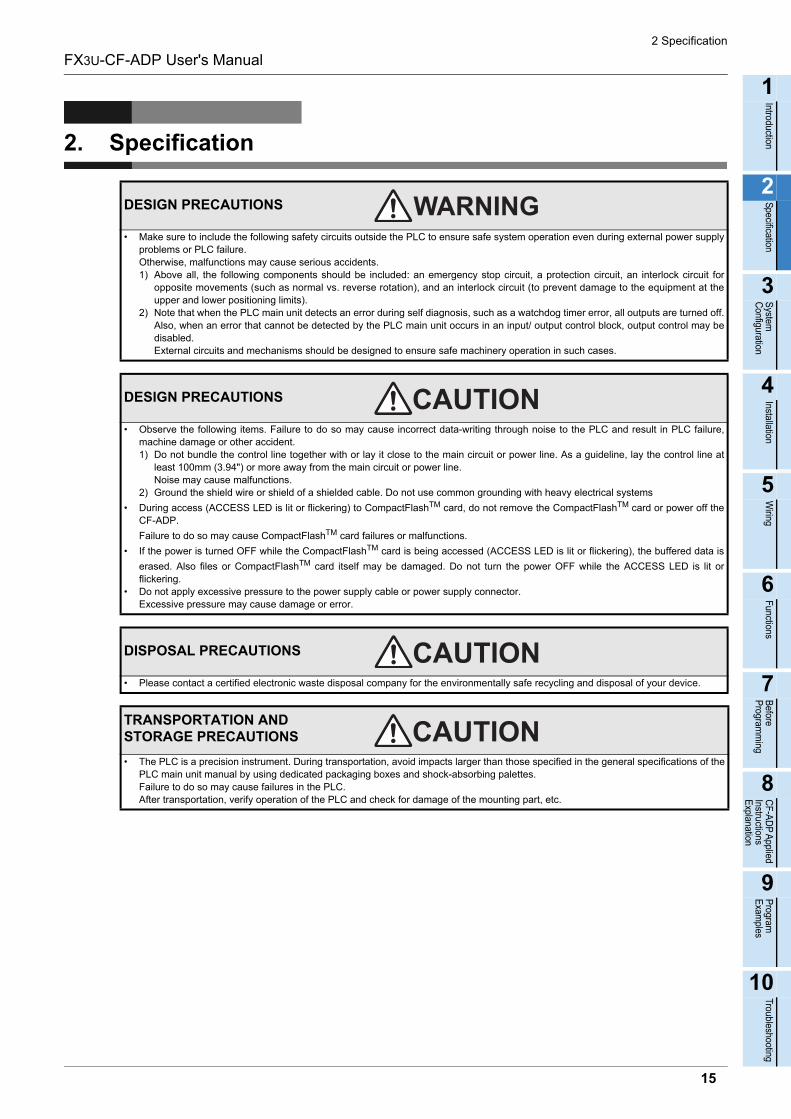
DESIGN PRECAUTIONS
• Make sure to include the following safety circuits outside the PLC to ensure safe system operation even during external power supplyproblems or PLC failure.Otherwise, malfunctions may cause serious accidents.1) Above all, the following components should be included: an emergency stop circuit, a protection circuit, an interlock circuit for
opposite movements (such as normal vs. reverse rotation), and an interlock circuit (to prevent damage to the equipment at theupper and lower positioning limits).
2) Note that when the PLC main unit detects an error during self diagnosis, such as a watchdog timer error, all outputs are turned off.Also, when an error that cannot be detected by the PLC main unit occurs in an input/ output control block, output control may bedisabled.External circuits and mechanisms should be designed to ensure safe machinery operation in such cases.
DESIGN PRECAUTIONS
• Observe the following items. Failure to do so may cause incorrect data-writing through noise to the PLC and result in PLC failure,machine damage or other accident.1) Do not bundle the control line together with or lay it close to the main circuit or power line. As a guideline, lay the control line at
least 100mm (3.94") or more away from the main circuit or power line.Noise may cause malfunctions.
2) Ground the shield wire or shield of a shielded cable. Do not use common grounding with heavy electrical systems
• During access (ACCESS LED is lit or flickering) to CompactFlashTM card, do not remove the CompactFlashTM card or power off theCF-ADP.
Failure to do so may cause CompactFlashTM card failures or malfunctions.
• If the power is turned OFF while the CompactFlashTM card is being accessed (ACCESS LED is lit or flickering), the buffered data is
erased. Also files or CompactFlashTM card itself may be damaged. Do not turn the power OFF while the ACCESS LED is lit orflickering.
• Do not apply excessive pressure to the power supply cable or power supply connector. Excessive pressure may cause damage or error.
DISPOSAL PRECAUTIONS
• Please contact a certified electronic waste disposal company for the environmentally safe recycling and disposal of your device.
TRANSPORTATION AND STORAGE PRECAUTIONS
• The PLC is a precision instrument. During transportation, avoid impacts larger than those specified in the general specifications of thePLC main unit manual by using dedicated packaging boxes and shock-absorbing palettes.Failure to do so may cause failures in the PLC.After transportation, verify operation of the PLC and check for damage of the mounting part, etc.
15
2 Specification
2.1 General specificationsFX3U-CF-ADP User's Manual
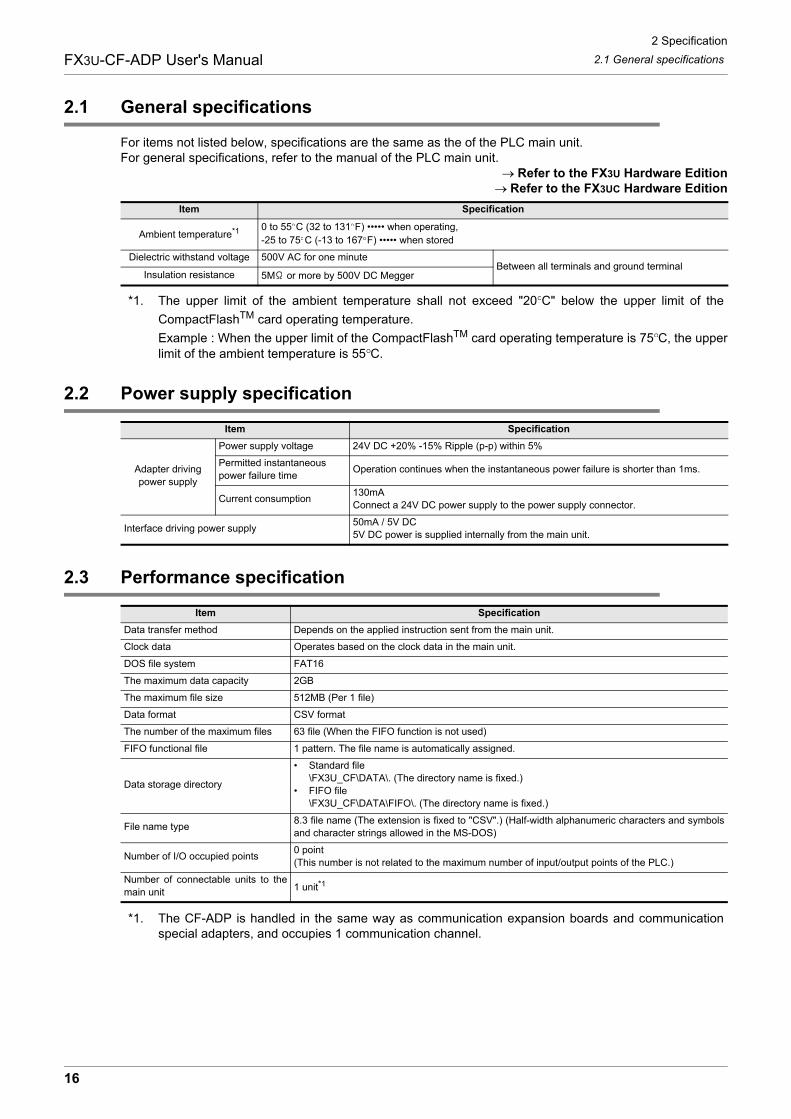
2.1 General specifications
For items not listed below, specifications are the same as the of the PLC main unit.For general specifications, refer to the manual of the PLC main unit.
Refer to the FX3U Hardware EditionRefer to the FX3UC Hardware Edition
*1. The upper limit of the ambient temperature shall not exceed "20 C" below the upper limit of the
CompactFlashTM card operating temperature.
Example : When the upper limit of the CompactFlashTM card operating temperature is 75 C, the upperlimit of the ambient temperature is 55 C.
2.2 Power supply specification
2.3 Performance specification
*1. The CF-ADP is handled in the same way as communication expansion boards and communicationspecial adapters, and occupies 1 communication channel.
Item Specification
Ambient temperature*1 0 to 55 C (32 to 131 F) ••••• when operating, -25 to 75 C (-13 to 167 F) ••••• when stored
Dielectric withstand voltage 500V AC for one minuteBetween all terminals and ground terminal
Insulation resistance 5M or more by 500V DC Megger
Item Specification
Adapter drivingpower supply
Power supply voltage 24V DC +20% -15% Ripple (p-p) within 5%
Permitted instantaneouspower failure time
Operation continues when the instantaneous power failure is shorter than 1ms.
Current consumption130mAConnect a 24V DC power supply to the power supply connector.
Interface driving power supply50mA / 5V DC5V DC power is supplied internally from the main unit.
Item Specification
Data transfer method Depends on the applied instruction sent from the main unit.
Clock data Operates based on the clock data in the main unit.
DOS file system FAT16
The maximum data capacity 2GB
The maximum file size 512MB (Per 1 file)
Data format CSV format
The number of the maximum files 63 file (When the FIFO function is not used)
FIFO functional file 1 pattern. The file name is automatically assigned.
Data storage directory
• Standard file\FX3U_CF\DATA\. (The directory name is fixed.)
• FIFO file\FX3U_CF\DATA\FIFO\. (The directory name is fixed.)
File name type8.3 file name (The extension is fixed to "CSV".) (Half-width alphanumeric characters and symbolsand character strings allowed in the MS-DOS)
Number of I/O occupied points0 point (This number is not related to the maximum number of input/output points of the PLC.)
Number of connectable units to themain unit 1 unit*1
16
2 Specification
2.4 CF card ACCESS switch specificationFX3U-CF-ADP User's Manual
1
Introduction
2
Specification
3
System
C
onfiguration
4
Installation
5
Wiring
6
Functions
7
Before
Program
ming
8
CF-A
DP
Applied
Instructions E
xplanation
9
Program
E
xamples
10
Troubleshooting
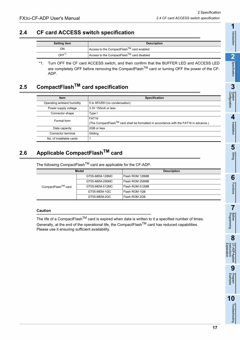
2.4 CF card ACCESS switch specification
*1. Turn OFF the CF card ACCESS switch, and then confirm that the BUFFER LED and ACCESS LED
are completely OFF before removing the CompactFlashTM card or turning OFF the power of the CF-ADP.
2.5 CompactFlashTM card specification
2.6 Applicable CompactFlashTM card
The following CompactFlashTM card are applicable for the CF-ADP.
Caution
The life of a CompactFlashTM card is expired when data is written to it a specified number of times.
Generally, at the end of the operational life, the CompactFlashTM card has reduced capabilities.Please use it ensuring sufficient availability.
Setting item Description
ON Access to the CompactFlashTM card enabled
OFF*1 Access to the CompactFlashTM card disabled
Item Specification
Operating ambient humidity 5 to 95%RH (no condensation)
Power supply voltage 3.3V 150mA or less
Connector shape Type I
Format formFAT16
(The CompactFlashTM card shall be formatted in accordance with the FAT16 in advance.)
Data capacity 2GB or less
Connector terminal Gilding
No. of installable cards 1
Model Description
CompactFlashTM card
GT05-MEM-128MC Flash ROM 128MB
GT05-MEM-256MC Flash ROM 256MB
GT05-MEM-512MC Flash ROM 512MB
GT05-MEM-1GC Flash ROM 1GB
GT05-MEM-2GC Flash ROM 2GB
17
3 System Configuration
3.1 General configurationFX3U-CF-ADP User's Manual
3. System Configuration
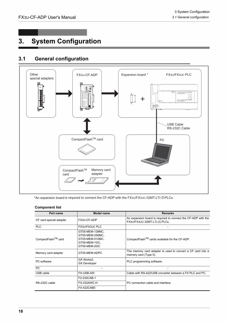
3.1 General configuration
Component list
Part name Model name Remarks
CF card special adapter FX3U-CF-ADPAn expansion board is required to connect the CF-ADP with theFX3U/FX3UC-32MT-LT(-2) PLCs.
PLC FX3U/FX3UC PLC -
CompactFlashTM card
GT05-MEM-128MC,GT05-MEM-256MC,GT05-MEM-512MC,GT05-MEM-1GC,GT05-MEM-2GC
CompactFlashTM cards available for the CF-ADP.
Memory card adapter GT05-MEM-ADPCThe memory card adapter is used to convert a CF card into amemory card (Type II).
PC softwareGX Works2,GX Developer
PLC programming software.
PC - -
USB cable FX-USB-AW Cable with RS-422/USB converter between a FX PLC and PC.
RS-232C cable
F2-232CAB-1
PC connection cable and interface.FX-232AWC-H
FX-422CAB0
CompactFlashTM card
CompactFlashTM card
Memory card adapter
*An expansion board
18
3 System Configuration
3.2 Applicable PLCFX3U-CF-ADP User's Manual
1
Introduction
2
Specification
3
System
C
onfiguration
4
Installation
5
Wiring
6
Functions
7
Before
Program
ming
8
CF-A
DP
Applied
Instructions E
xplanation
9
Program
E
xamples
10
Troubleshooting
3.2 Applicable PLC
3.2.1 Connectable PLC
The version number can be checked by reading the last three digits of device D8001/D8101.
*1. An expansion board is required to connect the CF-ADP with FX3U/FX3UC-32MT-LT(-2) PLCs.
*2. FX3UC-32MT-LT-2 Ver. 2.70 or later is applicable.
3.2.2 Applicable versions of the programming tool
Use the programming tool with the following version number to create programs for the CF-ADP of the FX3U/FX3UC Series PLC.
Caution
If a programming tool with the wrong version number is used, programming will not be possible.
3.3 Connection with PLC
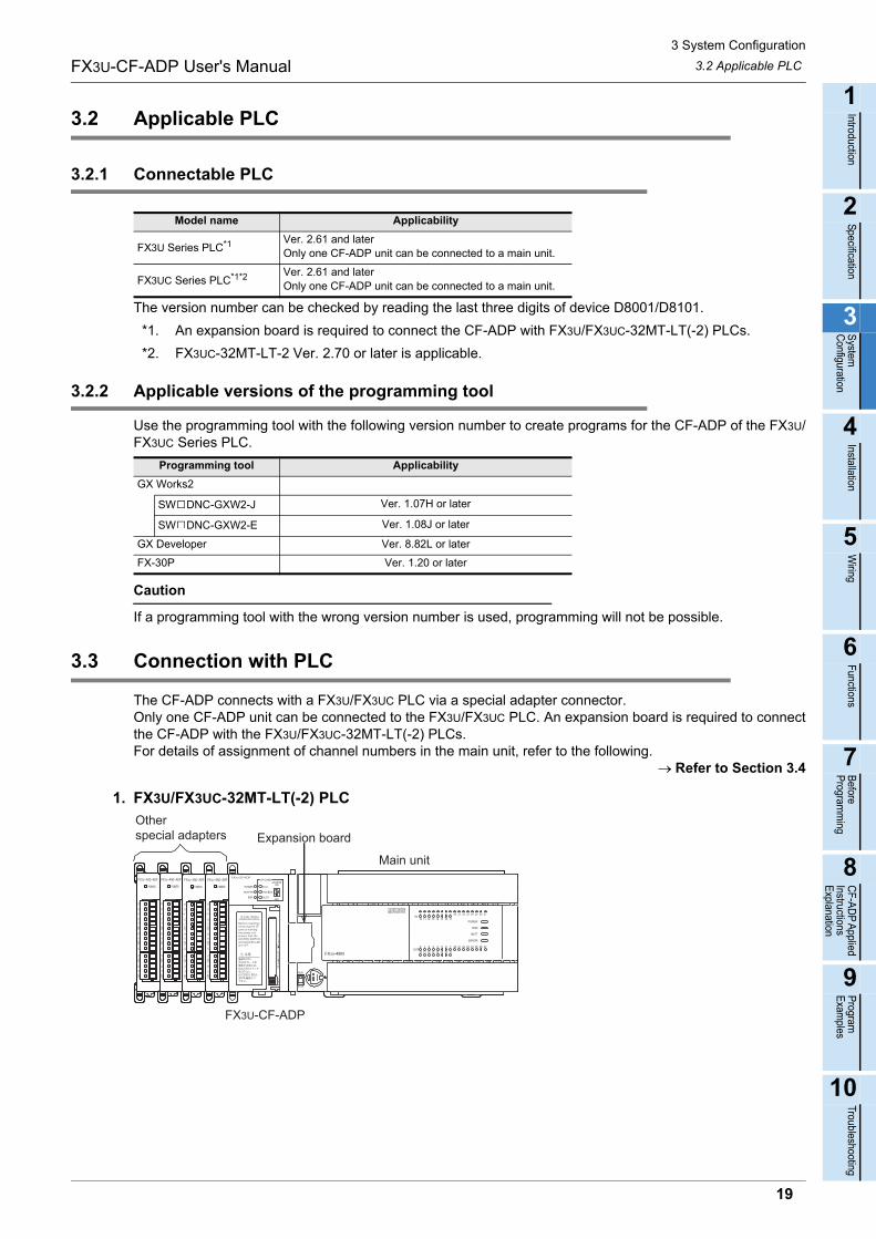
The CF-ADP connects with a FX3U/FX3UC PLC via a special adapter connector.Only one CF-ADP unit can be connected to the FX3U/FX3UC PLC. An expansion board is required to connectthe CF-ADP with the FX3U/FX3UC-32MT-LT(-2) PLCs.For details of assignment of channel numbers in the main unit, refer to the following.
Refer to Section 3.4
1. FX3U/FX3UC-32MT-LT(-2) PLC
Model name Applicability
FX3U Series PLC*1 Ver. 2.61 and laterOnly one CF-ADP unit can be connected to a main unit.
FX3UC Series PLC*1*2 Ver. 2.61 and laterOnly one CF-ADP unit can be connected to a main unit.
Programming tool Applicability
GX Works2
SW DNC-GXW2-J Ver. 1.07H or later
SW DNC-GXW2-E Ver. 1.08J or later
GX Developer Ver. 8.82L or later
FX-30P Ver. 1.20 or later
Otherspecial adapters Expansion board
Main unit
FX3U-CF-ADP
19
3 System Configuration
3.4 Assignment of channelsFX3U-CF-ADP User's Manual
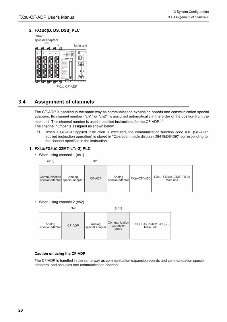
2. FX3UC(D, DS, DSS) PLC
3.4 Assignment of channels
The CF-ADP is handled in the same way as communication expansion boards and communication specialadapters. Its channel number ("ch1" or "ch2") is assigned automatically in the order of the position from the
main unit. This channel number is used in applied instructions for the CF-ADP.*1
The channel number is assigned as shown below.
*1. When a CF-ADP applied instruction is executed, the communication function code K10 (CF-ADPapplied instruction operation) is stored in "Operation mode display (D8419/D8439)" corresponding tothe channel specified in the instruction.
1. FX3U/FX3UC-32MT-LT(-2) PLC
• When using channel 1 (ch1)
• When using channel 2 (ch2)
Caution on using the CF-ADP
The CF-ADP is handled in the same way as communication expansion boards and communication special adapters, and occupies one communication channel.
Otherspecial adapters
Main unit
FX3U-CF-ADP
FX3U, FX3UC-32MT-LT(-2)Main unitFX3U-CNV-BDCF-ADP
ch1
Analogspecial adapter
Communicationspecial adapter
(ch2)
Analogspecial adapter
FX3U, FX3UC-32MT-LT(-2)Main unit
Communicationexpansion
boardCF-ADP
ch2 (ch1)
Analogspecial adapter
Analogspecial adapter
20
3 System Configuration
3.4 Assignment of channelsFX3U-CF-ADP User's Manual
1
Introduction
2
Specification
3
System
C
onfiguration
4
Installation
5
Wiring
6
Functions
7
Before
Program
ming
8
CF-A
DP
Applied
Instructions E
xplanation
9
Program
E
xamples
10
Troubleshooting
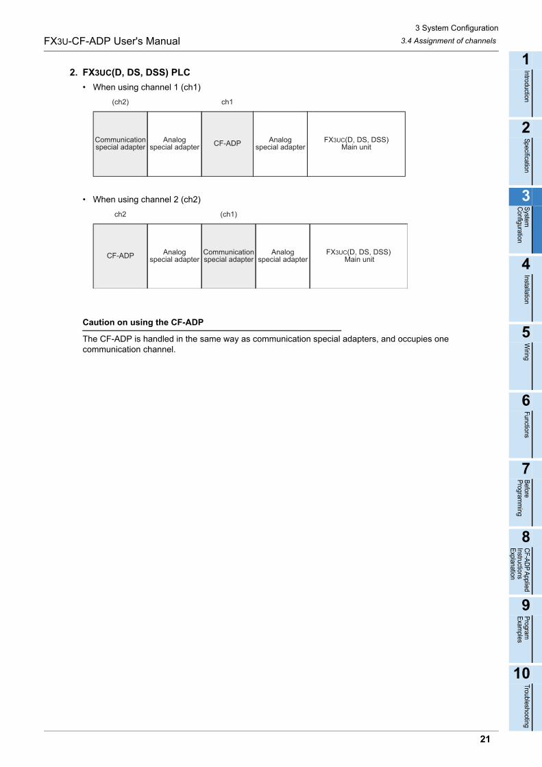
2. FX3UC(D, DS, DSS) PLC
• When using channel 1 (ch1)
• When using channel 2 (ch2)
Caution on using the CF-ADP
The CF-ADP is handled in the same way as communication special adapters, and occupies one communication channel.
FX3UC(D, DS, DSS)Main unitCF-ADPCommunication
special adapter
(ch2) ch1
Analogspecial adapter
Analogspecial adapter
FX3UC(D, DS, DSS) Main unit
Communicationspecial adapterCF-ADP
ch2 (ch1)
Analogspecial adapter
Analogspecial adapter
21
4 Installation
FX3U-CF-ADP User's Manual
4. Installation
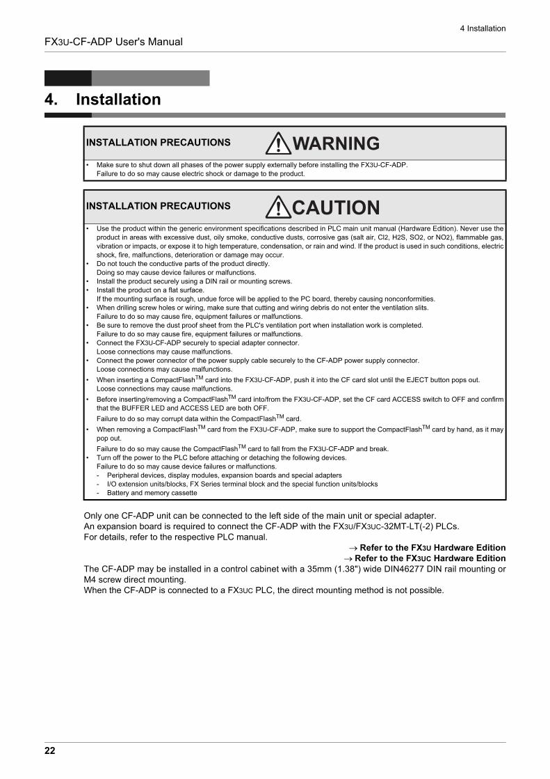
Only one CF-ADP unit can be connected to the left side of the main unit or special adapter.An expansion board is required to connect the CF-ADP with the FX3U/FX3UC-32MT-LT(-2) PLCs.For details, refer to the respective PLC manual.
Refer to the FX3U Hardware EditionRefer to the FX3UC Hardware Edition
The CF-ADP may be installed in a control cabinet with a 35mm (1.38") wide DIN46277 DIN rail mounting orM4 screw direct mounting. When the CF-ADP is connected to a FX3UC PLC, the direct mounting method is not possible.
INSTALLATION PRECAUTIONS
• Make sure to shut down all phases of the power supply externally before installing the FX3U-CF-ADP.Failure to do so may cause electric shock or damage to the product.
INSTALLATION PRECAUTIONS
• Use the product within the generic environment specifications described in PLC main unit manual (Hardware Edition). Never use theproduct in areas with excessive dust, oily smoke, conductive dusts, corrosive gas (salt air, Cl2, H2S, SO2, or NO2), flammable gas,vibration or impacts, or expose it to high temperature, condensation, or rain and wind. If the product is used in such conditions, electricshock, fire, malfunctions, deterioration or damage may occur.
• Do not touch the conductive parts of the product directly.Doing so may cause device failures or malfunctions.
• Install the product securely using a DIN rail or mounting screws.• Install the product on a flat surface.
If the mounting surface is rough, undue force will be applied to the PC board, thereby causing nonconformities.• When drilling screw holes or wiring, make sure that cutting and wiring debris do not enter the ventilation slits.
Failure to do so may cause fire, equipment failures or malfunctions.• Be sure to remove the dust proof sheet from the PLC's ventilation port when installation work is completed.
Failure to do so may cause fire, equipment failures or malfunctions.• Connect the FX3U-CF-ADP securely to special adapter connector.
Loose connections may cause malfunctions.• Connect the power connector of the power supply cable securely to the CF-ADP power supply connector.
Loose connections may cause malfunctions.
• When inserting a CompactFlashTM card into the FX3U-CF-ADP, push it into the CF card slot until the EJECT button pops out.Loose connections may cause malfunctions.
• Before inserting/removing a CompactFlashTM card into/from the FX3U-CF-ADP, set the CF card ACCESS switch to OFF and confirmthat the BUFFER LED and ACCESS LED are both OFF.
Failure to do so may corrupt data within the CompactFlashTM card.
• When removing a CompactFlashTM card from the FX3U-CF-ADP, make sure to support the CompactFlashTM card by hand, as it maypop out.
Failure to do so may cause the CompactFlashTM card to fall from the FX3U-CF-ADP and break.• Turn off the power to the PLC before attaching or detaching the following devices.
Failure to do so may cause device failures or malfunctions.- Peripheral devices, display modules, expansion boards and special adapters- I/O extension units/blocks, FX Series terminal block and the special function units/blocks- Battery and memory cassette
22
4 Installation
4.1 CF-ADP ConnectionFX3U-CF-ADP User's Manual
1
Introduction
2
Specification
3
System
C
onfiguration
4
Installation
5
Wiring
6
Functions
7
Before
Program
ming
8
CF-A
DP
Applied
Instructions E
xplanation
9
Program
E
xamples
10
Troubleshooting
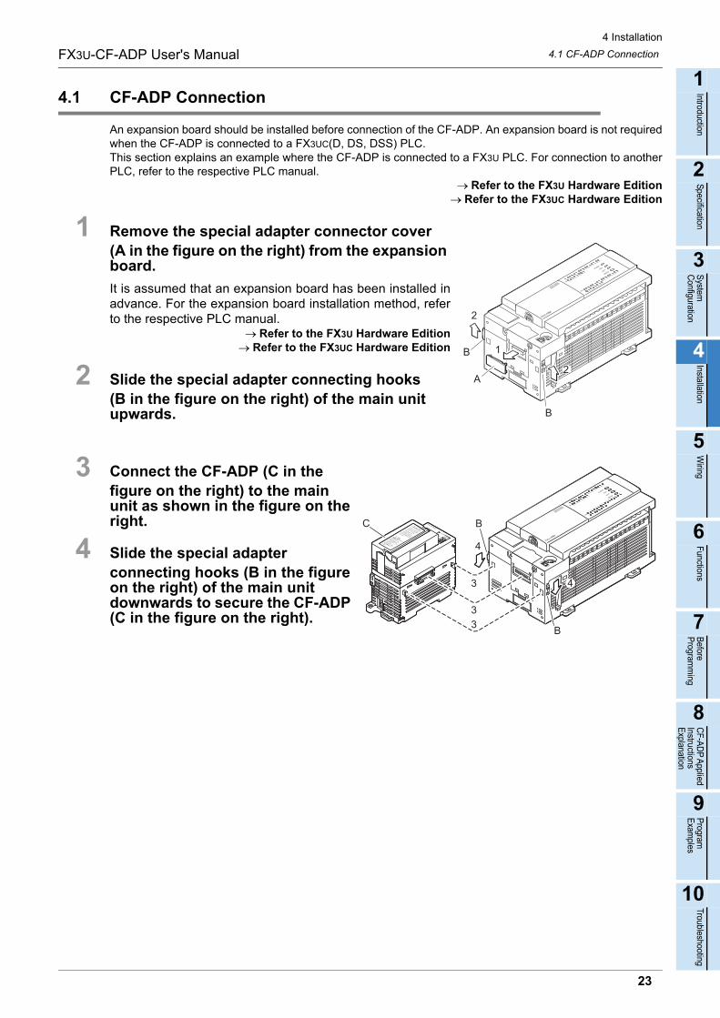
4.1 CF-ADP Connection
An expansion board should be installed before connection of the CF-ADP. An expansion board is not requiredwhen the CF-ADP is connected to a FX3UC(D, DS, DSS) PLC.This section explains an example where the CF-ADP is connected to a FX3U PLC. For connection to anotherPLC, refer to the respective PLC manual.
Refer to the FX3U Hardware EditionRefer to the FX3UC Hardware Edition
1 Remove the special adapter connector cover (A in the figure on the right) from the expansion board.
It is assumed that an expansion board has been installed inadvance. For the expansion board installation method, referto the respective PLC manual.
Refer to the FX3U Hardware EditionRefer to the FX3UC Hardware Edition
2 Slide the special adapter connecting hooks (B in the figure on the right) of the main unit upwards.
3 Connect the CF-ADP (C in the figure on the right) to the main unit as shown in the figure on the right.
4 Slide the special adapter connecting hooks (B in the figure on the right) of the main unit downwards to secure the CF-ADP (C in the figure on the right).
2
2
B
A
B 1
4
4
B
B
3
33
C
23
4 Installation
4.2 DIN rail mountingFX3U-CF-ADP User's Manual
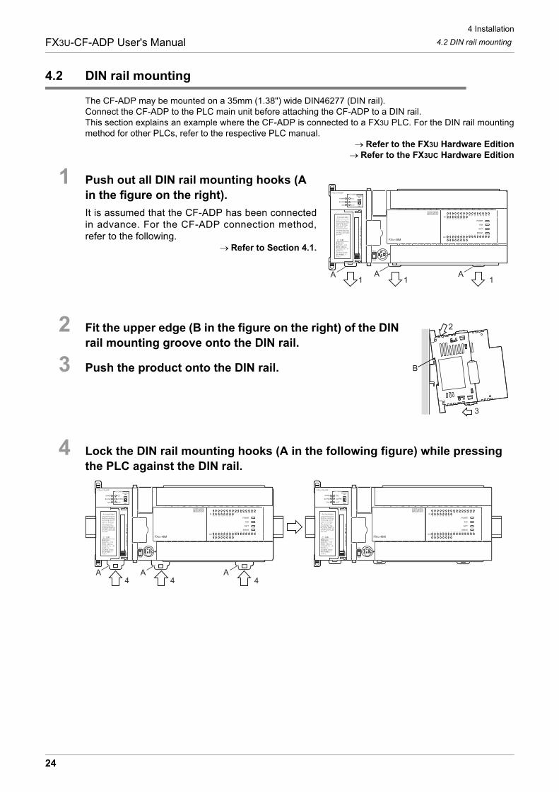
4.2 DIN rail mounting
The CF-ADP may be mounted on a 35mm (1.38") wide DIN46277 (DIN rail).Connect the CF-ADP to the PLC main unit before attaching the CF-ADP to a DIN rail.This section explains an example where the CF-ADP is connected to a FX3U PLC. For the DIN rail mountingmethod for other PLCs, refer to the respective PLC manual.
Refer to the FX3U Hardware EditionRefer to the FX3UC Hardware Edition
1 Push out all DIN rail mounting hooks (A in the figure on the right).
It is assumed that the CF-ADP has been connectedin advance. For the CF-ADP connection method,refer to the following.
Refer to Section 4.1.
2 Fit the upper edge (B in the figure on the right) of the DIN rail mounting groove onto the DIN rail.
3 Push the product onto the DIN rail.
4 Lock the DIN rail mounting hooks (A in the following figure) while pressing the PLC against the DIN rail.
111A A A
2
B
3
A44 4
AA
24
4 Installation
4.3 Direct mountingFX3U-CF-ADP User's Manual
1
Introduction
2
Specification
3
System
C
onfiguration
4
Installation
5
Wiring
6
Functions
7
Before
Program
ming
8
CF-A
DP
Applied
Instructions E
xplanation
9
Program
E
xamples
10
Troubleshooting
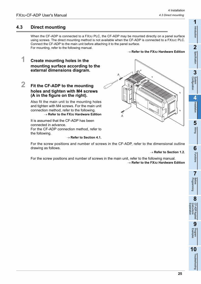
4.3 Direct mounting
When the CF-ADP is connected to a FX3U PLC, the CF-ADP may be mounted directly on a panel surfaceusing screws. The direct mounting method is not available when the CF-ADP is connected to a FX3UC PLC.Connect the CF-ADP to the main unit before attaching it to the panel surface.For mounting, refer to the following manual.
Refer to the FX3U Hardware Edition
1 Create mounting holes in the mounting surface according to the external dimensions diagram.
2 Fit the CF-ADP to the mounting holes and tighten with M4 screws (A in the figure on the right).
Also fit the main unit to the mounting holesand tighten with M4 screws. For the main unitconnection method, refer to the following.
Refer to the FX3U Hardware Edition
It is assumed that the CF-ADP has been connected in advance. For the CF-ADP connection method, refer tothe following.
Refer to Section 4.1.
For the screw positions and number of screws in the CF-ADP, refer to the dimensional outlinedrawing as follows.
Refer to Section 1.2.
For the screw positions and number of screws in the main unit, refer to the following manual.Refer to the FX3U Hardware Edition
A
A
25
4 Installation
4.4 Inserting and Removal ProceduresFX3U-CF-ADP User's Manual
4.4 Inserting and Removal Procedures
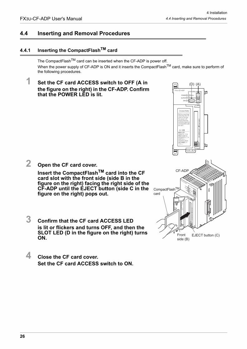
4.4.1 Inserting the CompactFlashTM card
The CompactFlashTM card can be inserted when the CF-ADP is power off.
When the power supply of CF-ADP is ON and it inserts the CompactFlashTM card, make sure to perform ofthe following procedures.
1 Set the CF card ACCESS switch to OFF (A in the figure on the right) in the CF-ADP. Confirm that the POWER LED is lit.
2 Open the CF card cover.
Insert the CompactFlashTM card into the CF card slot with the front side (side B in the figure on the right) facing the right side of the CF-ADP until the EJECT button (side C in the figure on the right) pops out.
3 Confirm that the CF card ACCESS LED is lit or flickers and turns OFF, and then the SLOT LED (D in the figure on the right) turns ON.
4 Close the CF card cover.Set the CF card ACCESS switch to ON.
(A)(D)
Front side (B)
CompactFlashTM card
CF-ADP
EJECT button (C)
26
4 Installation
4.4 Inserting and Removal ProceduresFX3U-CF-ADP User's Manual
1
Introduction
2
Specification
3
System
C
onfiguration
4
Installation
5
Wiring
6
Functions
7
Before
Program
ming
8
CF-A
DP
Applied
Instructions E
xplanation
9
Program
E
xamples
10
Troubleshooting
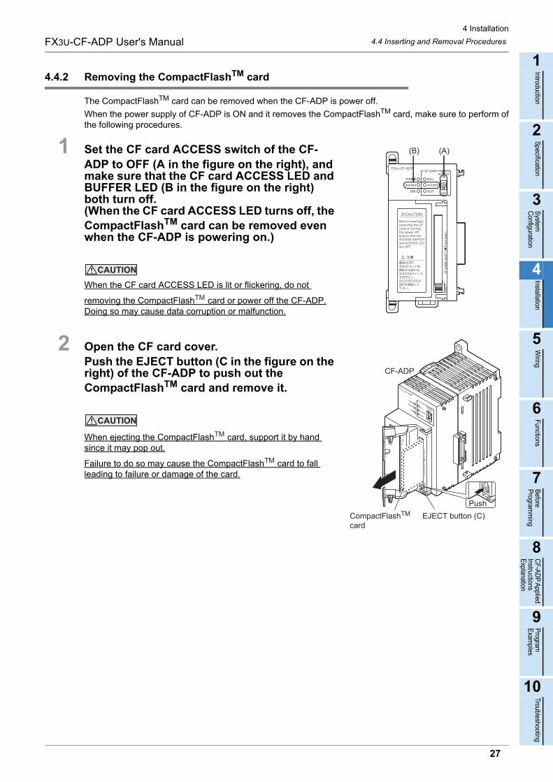
4.4.2 Removing the CompactFlashTM card
The CompactFlashTM card can be removed when the CF-ADP is power off.
When the power supply of CF-ADP is ON and it removes the CompactFlashTM card, make sure to perform ofthe following procedures.
1 Set the CF card ACCESS switch of the CF-ADP to OFF (A in the figure on the right), and make sure that the CF card ACCESS LED and BUFFER LED (B in the figure on the right) both turn off.(When the CF card ACCESS LED turns off, the CompactFlashTM card can be removed even when the CF-ADP is powering on.)
When the CF card ACCESS LED is lit or flickering, do not
removing the CompactFlash card or power off the CF-ADP.Doing so may cause data corruption or malfunction.
2 Open the CF card cover.Push the EJECT button (C in the figure on the right) of the CF-ADP to push out the CompactFlashTM card and remove it.
When ejecting the CompactFlash card, support it by hand since it may pop out.
Failure to do so may cause the CompactFlash card to fall leading to failure or damage of the card.
(A)(B)
TM
PushCompactFlashTM card
CF-ADP
EJECT button (C)
TM
TM
27
5 Wiring
FX3U-CF-ADP User's Manual
5. Wiring
DESIGN PRECAUTIONS
• Make sure to include the following safety circuits outside the PLC to ensure safe system operation even during external power supplyproblems or PLC failure.Otherwise, malfunctions may cause serious accidents.1) Above all, the following components should be included: an emergency stop circuit, a protection circuit, an interlock circuit for
opposite movements (such as normal vs. reverse rotation), and an interlock circuit (to prevent damage to the equipment at theupper and lower positioning limits).
2) Note that when the PLC main unit detects an error during self diagnosis, such as a watchdog timer error, all outputs are turned off.Also, when an error that cannot be detected by the PLC main unit occurs in an input/ output control block, output control may bedisabled.External circuits and mechanisms should be designed to ensure safe machinery operation in such cases.
DESIGN PRECAUTIONS
• Observe the following items. Failure to do so may cause incorrect data-writing through noise to the PLC and result in PLC failure,machine damage or other accident.1) Do not bundle the control line together with or lay it close to the main circuit or power line. As a guideline, lay the control line at
least 100mm (3.94") or more away from the main circuit or power line.Noise may cause malfunctions.
2) Ground the shield wire or shield of a shielded cable. Do not use common grounding with heavy electrical systems
• During access (ACCESS LED is lit or flickering) to CompactFlashTM card, do not remove the CompactFlashTM card or power off theCF-ADP.
Failure to do so may cause CompactFlashTM card failures or malfunctions.
• If the power is turned OFF while the CompactFlashTM card is being accessed (ACCESS LED is lit or flickering), the buffered data is
erased. Also files or CompactFlashTM card itself may be damaged. Do not turn the power OFF while the ACCESS LED is lit orflickering.
• Do not apply excessive pressure to the power supply cable or power supply connector. Excessive pressure may cause damage or error.
WIRING PRECAUTIONS
• Make sure to cut off all phases of the power supply externally before attempting wiring work.Failure to do so may cause electric shock or damage to the product.
WIRING PRECAUTIONS
• Connect the DC power supply wiring to the dedicated terminal described in this manual.If an AC power supply is connected to a DC input/output terminal or DC power supply terminal, the PLC will burn out.
• Connect the DC power supply wiring to the dedicated connector described in this manual.If an AC power supply is connected to a DC power supply connector, the PLC will burn out.
• When drilling screw holes or wiring, make sure that cutting and wiring debris do not enter the ventilation slits.Failure to do so may cause fire, equipment failures or malfunctions.
STARTUP AND MAINTENANCE PRECAUTIONS
• Make sure to connect the battery for memory backup correctly. Do not charge, disassemble, heat, short-circuit, or expose the batteryto fire.Doing so may rupture or ignite it.
• Do not touch any terminal while the PLC's power is on.Doing so may cause electric shock or malfunctions.
• Before modifying or disrupting the program in operation or running the PLC, carefully read through this manual and the associatedmanuals and ensure the safety of the operation.An operation error may damage the machinery or cause accidents.
28
5 Wiring
5.1 Which Power Supply Cable to UseFX3U-CF-ADP User's Manual
1
Introduction
2
Specification
3
System
C
onfiguration
4
Installation
5
Wiring
6
Functions
7
Before
Program
ming
8
CF-A
DP
Applied
Instructions E
xplanation
9
Program
E
xamples
10
Troubleshooting
5.1 Which Power Supply Cable to Use
The cable for connecting the CF-ADP power supply connector with the power supply is described here.
5.1.1 Power supply cable
A dedicated power supply cable offered as an accessory of the CF-ADP is available.
STARTUP AND MAINTENANCE PRECAUTIONS
• Do not disassemble or modify the PLC.Doing so may cause fire, equipment failures, or malfunctions.For repair, contact your local Mitsubishi Electric representative.
• Turn off the power to the PLC before attaching or detaching the following devices.Failure to do so may cause device failures or malfunctions.- Peripheral devices, display modules, expansion boards and special adapters- I/O extension units/blocks, FX Series terminal block and the special function units/blocks- Battery and memory cassette
Model name Length Remarks
FX2NC-100MPCB 1m (3’3") Accessory of CF-ADP
29
5 Wiring
5.2 Power Supply WiringFX3U-CF-ADP User's Manual
5.2 Power Supply Wiring
5.2.1 Power supply wiring
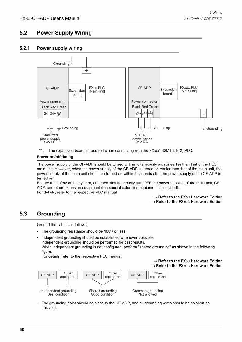
*1. The expansion board is required when connecting with the FX3UC-32MT-LT(-2) PLC.
Power-on/off timing
The power supply of the CF-ADP should be turned ON simultaneously with or earlier than that of the PLC main unit. However, when the power supply of the CF-ADP is turned on earlier than that of the main unit, the power supply of the main unit should be turned on within 5 seconds after the power supply of the CF-ADP is turned on.Ensure the safety of the system, and then simultaneously turn OFF the power supplies of the main unit, CF-ADP, and other extension equipment (the special extension equipment is included).For details, refer to the respective PLC manual.
Refer to the FX3U Hardware EditionRefer to the FX3UC Hardware Edition
5.3 Grounding
Ground the cables as follows
• The grounding resistance should be 100 or less.
• Independent grounding should be established whenever possible.Independent grounding should be performed for best results.When independent grounding is not configured, perform "shared grounding" as shown in the following figure.For details, refer to the respective PLC manual.
Refer to the FX3U Hardware EditionRefer to the FX3UC Hardware Edition
• The grounding point should be close to the CF-ADP, and all grounding wires should be as short as possible.
Grounding
FX3U PLC[Main unit]
CF-ADP
24+24-
Grounding
Stabilizedpower supply
24V DC
Power connectorGreenRedBlack
Expansion board
FX3UC PLC[Main unit]
Grounding
CF-ADP
24+24-
Grounding
Stabilizedpower supply
24V DC
Power connectorGreenRedBlack
Expansion board*1
CF-ADP Otherequipment
Shared groundingGood condition
Common groundingNot allowed
Independent groundingBest condition
CF-ADP Otherequipment CF-ADP Other
equipment
30
5 Wiring
5.4 Power OFF procedureFX3U-CF-ADP User's Manual
1
Introduction
2
Specification
3
System
C
onfiguration
4
Installation
5
Wiring
6
Functions
7
Before
Program
ming
8
CF-A
DP
Applied
Instructions E
xplanation
9
Program
E
xamples
10
Troubleshooting
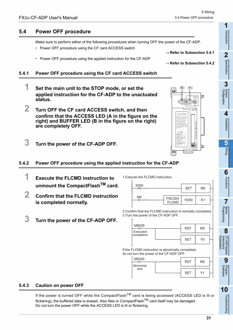
5.4 Power OFF procedure
Make sure to perform either of the following procedures when turning OFF the power of the CF-ADP.
• Power OFF procedure using the CF card ACCESS switchRefer to Subsection 5.4.1
• Power OFF procedure using the applied instruction for the CF-ADPRefer to Subsection 5.4.2
5.4.1 Power OFF procedure using the CF card ACCESS switch
1 Set the main unit to the STOP mode, or set the applied instruction for the CF-ADP to the unactuated status.
2 Turn OFF the CF card ACCESS switch, and then confirm that the ACCESS LED (A in the figure on the right) and BUFFER LED (B in the figure on the right) are completely OFF.
3 Turn the power of the CF-ADP OFF.
5.4.2 Power OFF procedure using the applied instruction for the CF-ADP
1 Execute the FLCMD instruction to
unmount the CompactFlashTM card.
2 Confirm that the FLCMD instruction is completed normally.
3 Turn the power of the CF-ADP OFF.
5.4.3 Caution on power OFF
If the power is turned OFF while the CompactFlashTM card is being accessed (ACCESS LED is lit or
flickering), the buffered data is erased. Also files or CompactFlashTM card itself may be damaged.Do not turn the power OFF while the ACCESS LED is lit or flickering.
(A)(B)
M0RSTM8329
1.Execute the FLCMD instruction,
K1H200 FNC304 FLCMD
M0
Y0SET
M0SETX000
Y1SET
M8029M0RST
If the FLCMD instruction is abnormally completed,do not turn the power of the CF-ADP OFF .
2.Confirm that the FLCMD instruction is normally completed.3.Turn the power of the CF-ADP OFF.
Executioncompletion
Abnormalend
31
5 Wiring
5.5 Connection of the power supply cableFX3U-CF-ADP User's Manual
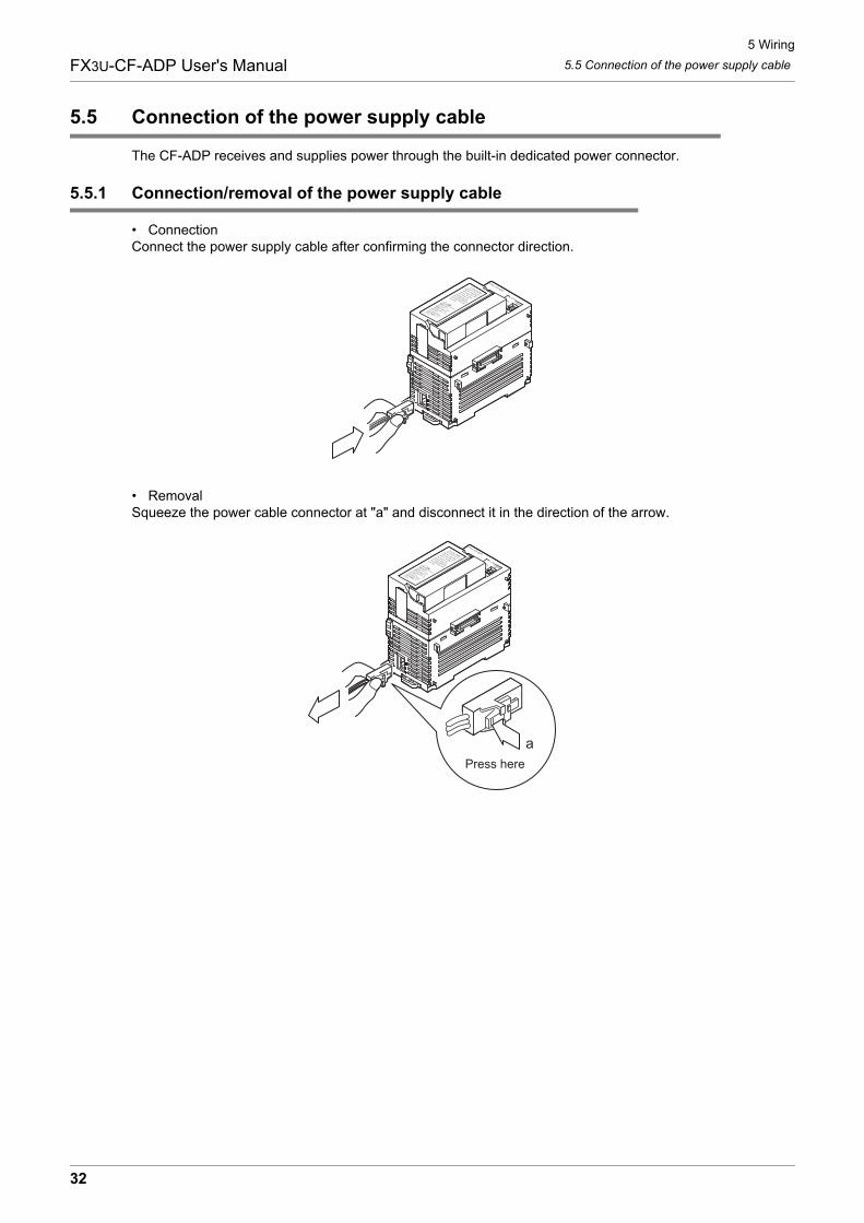
5.5 Connection of the power supply cable
The CF-ADP receives and supplies power through the built-in dedicated power connector.
5.5.1 Connection/removal of the power supply cable
• ConnectionConnect the power supply cable after confirming the connector direction.
• RemovalSqueeze the power cable connector at "a" and disconnect it in the direction of the arrow.
Press herea
32
6 Functions
6.1 Details of functionsFX3U-CF-ADP User's Manual
1
Introduction
2
Specification
3
System
C
onfiguration
4
Installation
5
Wiring
6
Functions
7
Before
Program
ming
8
CF-A
DP
Applied
Instructions E
xplanation
9
Program
E
xamples
10
Troubleshooting
6. Functions
6.1 Details of functions
The user can perform the following procedures for CompactFlashTM cards using applied instructions for theCF-ADP.
• Creating FIFO function files inside the CompactFlashTM card.(Only one pattern is available for FIFO function files. Multiple FIFO function files are created automatically with a predetermined file name. If the created FIFO function files exceed the allowable capacity, old files are deleted. The FIFO function is executed in units of files.)
• Creating files inside the CompactFlashTM card.(Up to 63 files can be created.)
• Deleting specified files stored in the CompactFlashTM card.
• Writing bit data, word data, double-word data, floating point data and character string data to a specified
file stored in the CompactFlashTM card.
Data can be written to the CompactFlashTM card using the following two methods:
- Data is directly written to the CompactFlashTM card without using the internal buffer. Up to 254 data points can be written to one line.
- Data is collected in the internal buffer. When the internal buffer becomes full, data is written to the
CompactFlashTM card. Up to 254 data points can be written to one line.
• Forcibly writing data of a specified file stored in the internal buffer to the CompactFlashTM card.
• Reading the number from the final line in a specified file stored in the CompactFlashTM card.
• Reading the data from a specified line in a specified file stored in the CompactFlashTM card.(Up to 254 data points can be read from one line.)
• Writing the data name.(Up to 254 data points names can be written.)
• Formatting the CompactFlashTM card.
• Sending a mount command to the CompactFlashTM card.
• Sending an unmount command to the CompactFlashTM card.
33
6 Functions
6.2 Status informationFX3U-CF-ADP User's Manual
6.2 Status information
The user can read the following status information using applied instructions for the CF-ADP.
• Detecting that a CompactFlashTM card is mounted.
• Detecting that the CompactFlashTM card is full.
• Detecting errors that have occurred in the CF-ADP.
• Reading error codes of the CF-ADP.
• Data capacity of the CompactFlashTM card. (Unit: kB)1(MB)=1024(kB), 1(GB)=1024(MB)=1,048,576(kB)Capacity less than 1 kB is regarded as "1 kB".
• Used space of the CompactFlashTM card. (Unit: kB)1(MB)=1024(kB), 1(GB)=1024(MB)=1,048,576(kB)Capacity less than 1 kB is regarded as "1 kB".
• Free space of the CompactFlashTM card. (Unit: kB)1(MB)=1024(kB), 1(GB)=1024(MB)=1,048,576(kB)Capacity less than 1 kB is regarded as "1 kB".
• File ID list.(File ID: The file name is associated with the file ID, and the file ID is used in sequence programs (applied instructions).)
• CF-ADP version information.
34
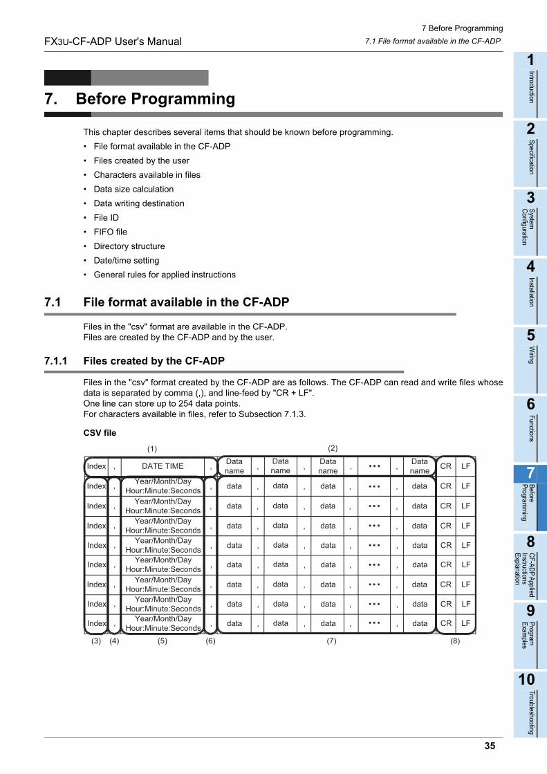
7 Before Programming
7.1 File format available in the CF-ADPFX3U-CF-ADP User's Manual
1
Introduction
2
Specification
3
System
C
onfiguration
4
Installation
5
Wiring
6
Functions
7
Before
Program
ming
8
CF-A
DP
Applied
Instructions E
xplanation
9
Program
E
xamples
10
Troubleshooting
7. Before Programming
This chapter describes several items that should be known before programming.
• File format available in the CF-ADP
• Files created by the user
• Characters available in files
• Data size calculation
• Data writing destination
• File ID
• FIFO file
• Directory structure
• Date/time setting
• General rules for applied instructions
7.1 File format available in the CF-ADP
Files in the "csv" format are available in the CF-ADP.Files are created by the CF-ADP and by the user.
7.1.1 Files created by the CF-ADP
Files in the "csv" format created by the CF-ADP are as follows. The CF-ADP can read and write files whosedata is separated by comma (,), and line-feed by "CR + LF".One line can store up to 254 data points.For characters available in files, refer to Subsection 7.1.3.
CSV file
DATE TIMEIndex , , ,, , , CRDataname
Dataname
Dataname
Dataname LF
Year/Month/DayHour:Minute:SecondsIndex , , ,, , , CRdata data data data LF
Year/Month/DayHour:Minute:SecondsIndex , , ,, , , CRdata data data data LF
Year/Month/DayHour:Minute:SecondsIndex , , ,, , , CRdata data data data LF
Year/Month/DayHour:Minute:SecondsIndex , , ,, , , CRdata data data data LF
Year/Month/DayHour:Minute:SecondsIndex , , ,, , , CRdata data data data LF
Year/Month/DayHour:Minute:SecondsIndex , , ,, , , CRdata data data data LF
Year/Month/DayHour:Minute:SecondsIndex , , ,, , , CRdata data data data LF
Year/Month/DayHour:Minute:SecondsIndex , , ,, , , CRdata data data data LF
(1) (2)
(3) (4) (5) (6) (7) (8)
35
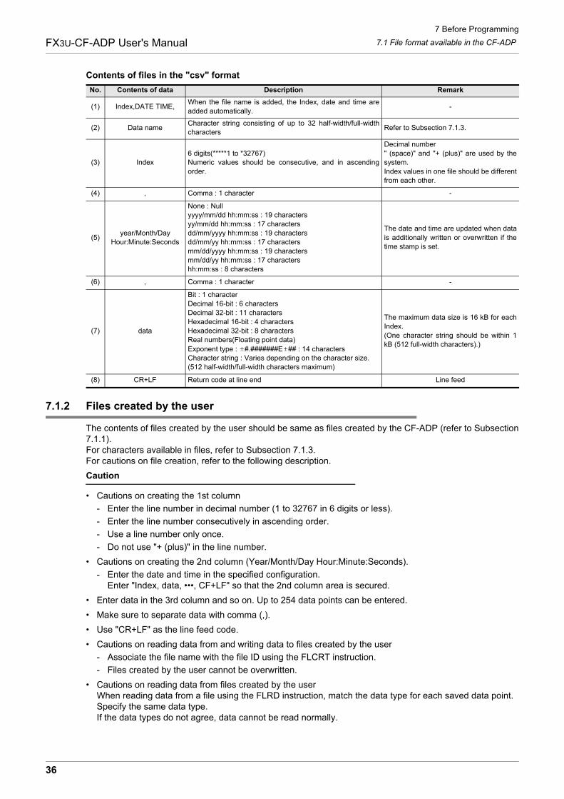
7 Before Programming
7.1 File format available in the CF-ADPFX3U-CF-ADP User's Manual
Contents of files in the "csv" format
7.1.2 Files created by the user
The contents of files created by the user should be same as files created by the CF-ADP (refer to Subsection7.1.1).For characters available in files, refer to Subsection 7.1.3.For cautions on file creation, refer to the following description.
Caution
• Cautions on creating the 1st column
- Enter the line number in decimal number (1 to 32767 in 6 digits or less).
- Enter the line number consecutively in ascending order.
- Use a line number only once.
- Do not use "+ (plus)" in the line number.
• Cautions on creating the 2nd column (Year/Month/Day Hour:Minute:Seconds).
- Enter the date and time in the specified configuration.Enter "Index, data, •••, CF+LF" so that the 2nd column area is secured.
• Enter data in the 3rd column and so on. Up to 254 data points can be entered.
• Make sure to separate data with comma (,).
• Use "CR+LF" as the line feed code.
• Cautions on reading data from and writing data to files created by the user
- Associate the file name with the file ID using the FLCRT instruction.
- Files created by the user cannot be overwritten.
• Cautions on reading data from files created by the userWhen reading data from a file using the FLRD instruction, match the data type for each saved data point. Specify the same data type.If the data types do not agree, data cannot be read normally.
No. Contents of data Description Remark
(1) Index,DATE TIME,When the file name is added, the Index, date and time areadded automatically.
-
(2) Data nameCharacter string consisting of up to 32 half-width/full-widthcharacters
Refer to Subsection 7.1.3.
(3) Index6 digits(*****1 to *32767)Numeric values should be consecutive, and in ascendingorder.
Decimal number" (space)" and "+ (plus)" are used by thesystem.Index values in one file should be differentfrom each other.
(4) , Comma : 1 character -
(5)year/Month/Day
Hour:Minute:Seconds
None : Nullyyyy/mm/dd hh:mm:ss : 19 charactersyy/mm/dd hh:mm:ss : 17 charactersdd/mm/yyyy hh:mm:ss : 19 charactersdd/mm/yy hh:mm:ss : 17 charactersmm/dd/yyyy hh:mm:ss : 19 charactersmm/dd/yy hh:mm:ss : 17 charactershh:mm:ss : 8 characters
The date and time are updated when datais additionally written or overwritten if thetime stamp is set.
(6) , Comma : 1 character -
(7) data
Bit : 1 characterDecimal 16-bit : 6 charactersDecimal 32-bit : 11 charactersHexadecimal 16-bit : 4 charactersHexadecimal 32-bit : 8 charactersReal numbers(Floating point data)Exponent type : #.#######E ## : 14 charactersCharacter string : Varies depending on the character size.(512 half-width/full-width characters maximum)
The maximum data size is 16 kB for eachIndex.(One character string should be within 1kB (512 full-width characters).)
(8) CR+LF Return code at line end Line feed
36
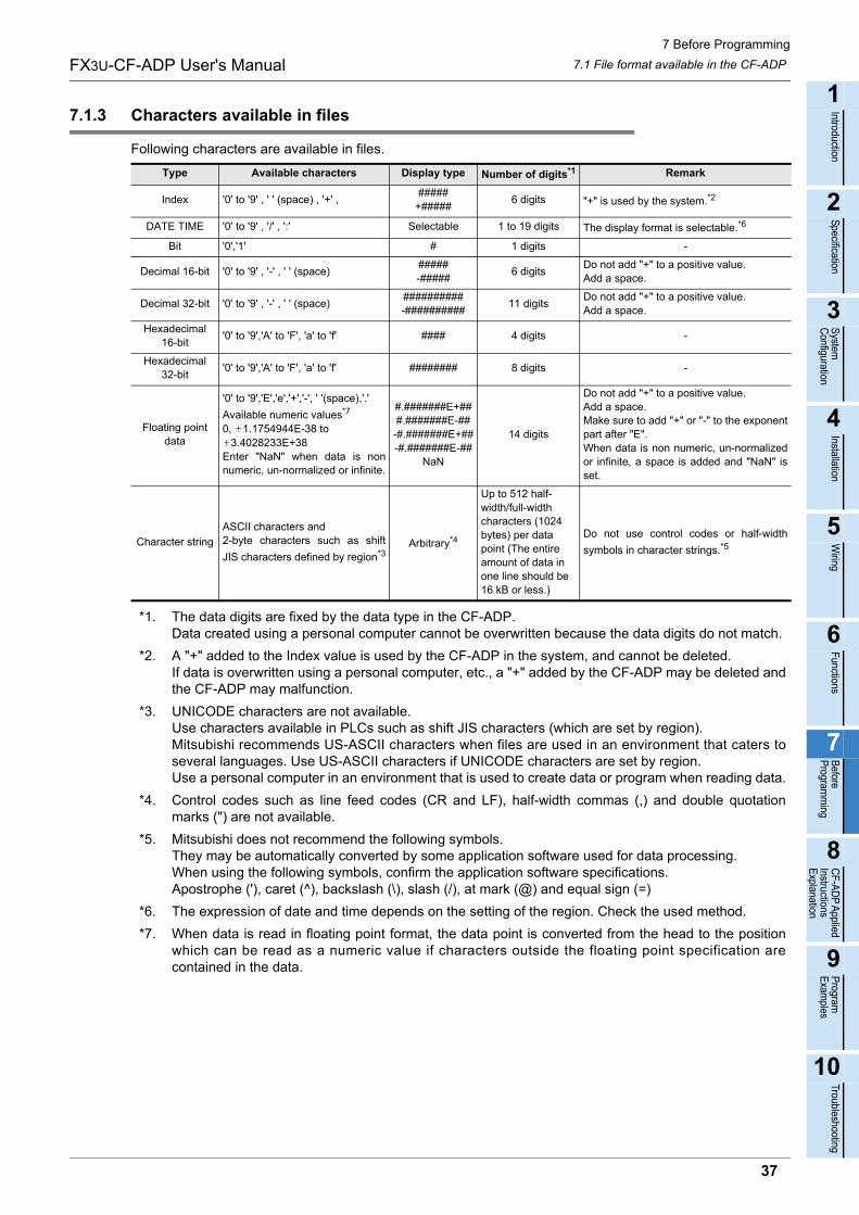
7 Before Programming
7.1 File format available in the CF-ADPFX3U-CF-ADP User's Manual
1
Introduction
2
Specification
3
System
C
onfiguration
4
Installation
5
Wiring
6
Functions
7
Before
Program
ming
8
CF-A
DP
Applied
Instructions E
xplanation
9
Program
E
xamples
10
Troubleshooting
7.1.3 Characters available in files
Following characters are available in files.
*1. The data digits are fixed by the data type in the CF-ADP.Data created using a personal computer cannot be overwritten because the data digits do not match.
*2. A "+" added to the Index value is used by the CF-ADP in the system, and cannot be deleted.If data is overwritten using a personal computer, etc., a "+" added by the CF-ADP may be deleted andthe CF-ADP may malfunction.
*3. UNICODE characters are not available.Use characters available in PLCs such as shift JIS characters (which are set by region).Mitsubishi recommends US-ASCII characters when files are used in an environment that caters toseveral languages. Use US-ASCII characters if UNICODE characters are set by region.Use a personal computer in an environment that is used to create data or program when reading data.
*4. Control codes such as line feed codes (CR and LF), half-width commas (,) and double quotationmarks (") are not available.
*5. Mitsubishi does not recommend the following symbols.They may be automatically converted by some application software used for data processing.When using the following symbols, confirm the application software specifications.Apostrophe ('), caret (^), backslash (\), slash (/), at mark (@) and equal sign (=)
*6. The expression of date and time depends on the setting of the region. Check the used method.
*7. When data is read in floating point format, the data point is converted from the head to the positionwhich can be read as a numeric value if characters outside the floating point specification arecontained in the data.
Type Available characters Display type Number of digits*1 Remark
Index '0' to '9' , ' ' (space) , '+' , #####
+#####6 digits "+" is used by the system.*2
DATE TIME '0' to '9' , '/' , ':' Selectable 1 to 19 digits The display format is selectable.*6
Bit '0','1' # 1 digits -
Decimal 16-bit '0' to '9' , '-' , ' ' (space)#####-#####
6 digitsDo not add "+" to a positive value.Add a space.
Decimal 32-bit '0' to '9' , '-' , ' ' (space)##########-##########
11 digitsDo not add "+" to a positive value.Add a space.
Hexadecimal16-bit
'0' to '9','A' to 'F', 'a' to 'f' #### 4 digits -
Hexadecimal32-bit
'0' to '9','A' to 'F', 'a' to 'f' ######## 8 digits -
Floating point data
'0' to '9','E','e','+','-', ' '(space),'.'
Available numeric values*7
0, 1.1754944E-38 to 3.4028233E+38
Enter "NaN" when data is nonnumeric, un-normalized or infinite.
#.#######E+###.#######E-##
-#.#######E+##-#.#######E-##
NaN
14 digits
Do not add "+" to a positive value. Add a space.Make sure to add "+" or "-" to the exponentpart after "E".When data is non numeric, un-normalizedor infinite, a space is added and "NaN" isset.
Character string
ASCII characters and 2-byte characters such as shift
JIS characters defined by region*3Arbitrary*4
Up to 512 half-width/full-widthcharacters (1024 bytes) per data point (The entire amount of data in one line should be 16 kB or less.)
Do not use control codes or half-width
symbols in character strings.*5
37
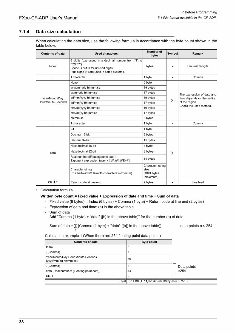
7 Before Programming
7.1 File format available in the CF-ADPFX3U-CF-ADP User's Manual
7.1.4 Data size calculation
When calculating the data size, use the following formula in accordance with the byte count shown in thetable below.
• Calculation formula
Written byte count = Fixed value + Expression of date and time + Sum of data
- Fixed value (9 bytes) = Index (6 bytes) + Comma (1 byte) + Return code at line end (2 bytes)
- Expression of date and time: (a) in the above table
- Sum of dataAdd "Comma (1 byte) + "data" ([b] in the above table)" for the number (n) of data.
- Calculation example 1 (When there are 254 floating point data points)
Contents of data Used charactersNumber of
bytesSymbol Remark
Index
6 digits (expressed in a decimal number from "1" to"32767")Space is put in for unused digits.Plus signs (+) are used in some systems.
6 bytes - Decimal 6 digits
, 1 character 1 byte - Comma
year/Month/Day Hour:Minute:Seconds
None 0 byte
(a)
The expression of date andtime depends on the settingof the region. Check the used method.
yyyy/mm/dd hh:mm:ss 19 bytes
yy/mm/dd hh:mm:ss 17 bytes
dd/mm/yyyy hh:mm:ss 19 bytes
dd/mm/yy hh:mm:ss 17 bytes
mm/dd/yyyy hh:mm:ss 19 bytes
mm/dd/yy hh:mm:ss 17 bytes
hh:mm:ss 8 bytes
, 1 character 1 byte - Comma
data
Bit 1 byte
(b) -
Decimal 16-bit 6 bytes
Decimal 32-bit 11 bytes
Hexadecimal 16-bit 4 bytes
Hexadecimal 32-bit 8 bytes
Real numbers(Floating point data)Exponent expression type= #.#######E ##
14 bytes
Character string(512 half-width/full-width characters maximum)
Character stringsize(1024 bytes maximum)
CR+LF Return code at line end 2 bytes - Line feed
Contents of data Byte count
Index 6
, (Comma) 1
Year/Month/Day Hour:Minute:Seconds(yyyy/mm/dd hh:mm:ss)
19
, (Comma) 1
data (Real numbers (Floating point data)) 14
CR+LF 2
Total 6+1+19+(1+14)×254+2=3838 bytes ≈ 3.75KB
Sum of data = ∑ {Comma (1 byte) + "data" ([b]) in the above table)} data points n ≤ 2541
n
Data points×254
38
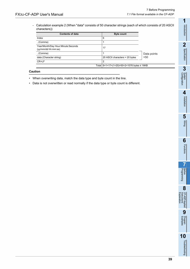
7 Before Programming
7.1 File format available in the CF-ADPFX3U-CF-ADP User's Manual
1
Introduction
2
Specification
3
System
C
onfiguration
4
Installation
5
Wiring
6
Functions
7
Before
Program
ming
8
CF-A
DP
Applied
Instructions E
xplanation
9
Program
E
xamples
10
Troubleshooting
- Calculation example 2 (When "data" consists of 50 character strings (each of which consists of 20 ASCII characters))
Caution
• When overwriting data, match the data type and byte count in the line.
• Data is not overwritten or read normally if the data type or byte count is different.
Contents of data Byte count
Index 6
, (Comma) 1
Year/Month/Day Hour:Minute:Seconds(yy/mm/dd hh:mm:ss)
17
, (Comma) 1
data (Character string) 20 ASCII characters = 20 bytes
CR+LF 2
Total 6+1+17+(1+20)×50+2=1076 bytes ≤ 16KB
Data points×50
39
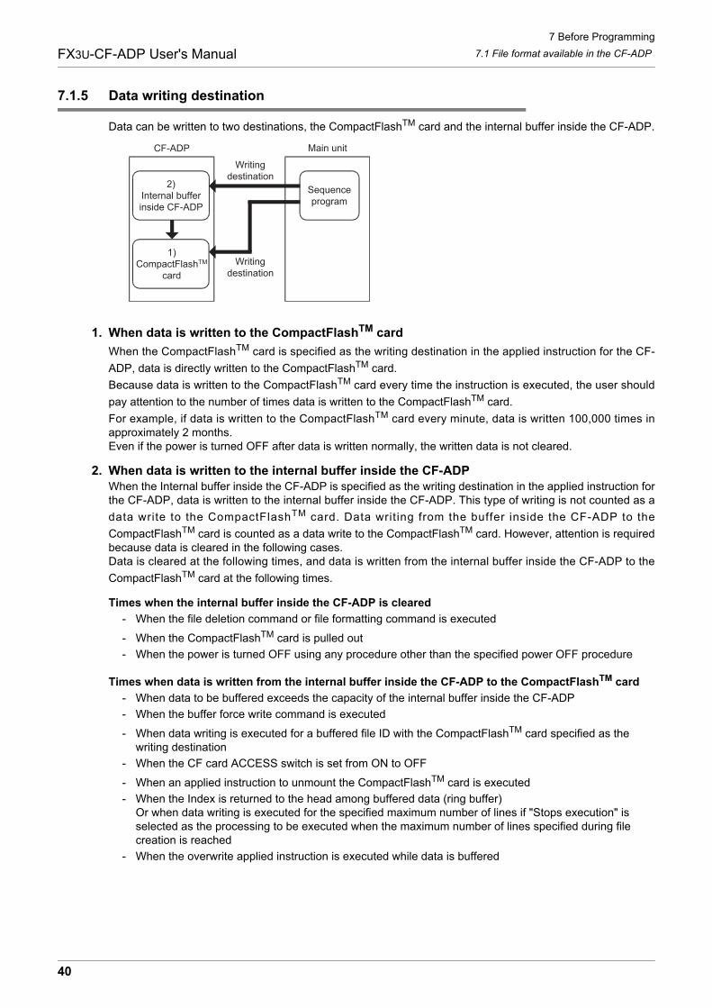
7 Before Programming
7.1 File format available in the CF-ADPFX3U-CF-ADP User's Manual
7.1.5 Data writing destination
Data can be written to two destinations, the CompactFlashTM card and the internal buffer inside the CF-ADP.
1. When data is written to the CompactFlashTM card
When the CompactFlashTM card is specified as the writing destination in the applied instruction for the CF-
ADP, data is directly written to the CompactFlashTM card.
Because data is written to the CompactFlashTM card every time the instruction is executed, the user should
pay attention to the number of times data is written to the CompactFlashTM card.
For example, if data is written to the CompactFlashTM card every minute, data is written 100,000 times inapproximately 2 months.Even if the power is turned OFF after data is written normally, the written data is not cleared.
2. When data is written to the internal buffer inside the CF-ADPWhen the Internal buffer inside the CF-ADP is specified as the writing destination in the applied instruction forthe CF-ADP, data is written to the internal buffer inside the CF-ADP. This type of writing is not counted as a
data write to the CompactFlashTM card. Data writing from the buffer inside the CF-ADP to the
CompactFlashTM card is counted as a data write to the CompactFlashTM card. However, attention is requiredbecause data is cleared in the following cases.Data is cleared at the following times, and data is written from the internal buffer inside the CF-ADP to the
CompactFlashTM card at the following times.
Times when the internal buffer inside the CF-ADP is cleared
- When the file deletion command or file formatting command is executed
- When the CompactFlashTM card is pulled out
- When the power is turned OFF using any procedure other than the specified power OFF procedure
Times when data is written from the internal buffer inside the CF-ADP to the CompactFlashTM card
- When data to be buffered exceeds the capacity of the internal buffer inside the CF-ADP
- When the buffer force write command is executed
- When data writing is executed for a buffered file ID with the CompactFlashTM card specified as the writing destination
- When the CF card ACCESS switch is set from ON to OFF
- When an applied instruction to unmount the CompactFlashTM card is executed
- When the Index is returned to the head among buffered data (ring buffer)Or when data writing is executed for the specified maximum number of lines if "Stops execution" is selected as the processing to be executed when the maximum number of lines specified during file creation is reached
- When the overwrite applied instruction is executed while data is buffered
Main unitCF-ADP
1)CompactFlashTM
card
Sequenceprogram
2)Internal bufferinside CF-ADP
Writingdestination
Writingdestination
40
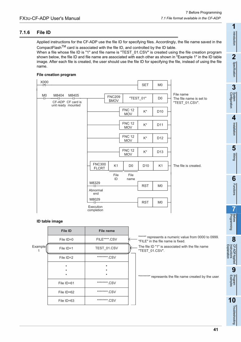
7 Before Programming
7.1 File format available in the CF-ADPFX3U-CF-ADP User's Manual
1
Introduction
2
Specification
3
System
C
onfiguration
4
Installation
5
Wiring
6
Functions
7
Before
Program
ming
8
CF-A
DP
Applied
Instructions E
xplanation
9
Program
E
xamples
10
Troubleshooting
7.1.6 File ID
Applied instructions for the CF-ADP use the file ID for specifying files. Accordingly, the file name saved in the
CompactFlashTM card is associated with the file ID, and controlled by the ID table.When a file whose file ID is "1" and file name is "TEST_01.CSV" is created using the file creation programshown below, the file ID and file name are associated with each other as shown in "Example 1" in the ID tableimage. After each file is created, the user should use the file ID for specifying the file, instead of using the filename.
File creation program
ID table image
D11K*
D12K*
The file is created.
D0"TEST_01"FNC209$MOV
M8405
CF card ismounted
M0 M8404
CF-ADPunit ready
File nameThe file name is set to"TEST_01.CSV".
D10K* FNC 12 MOV
D13K*
K1D10D0FNC300FLCRT
K1
M0SETX000
FileID
Filename
FNC 12 MOV
FNC 12 MOV
FNC 12 MOV
M0RSTM8329
Abnormalend
M0RSTM8029
Executioncompletion
File ID File neme
File ID=0 FILE****.CSV
File ID=1 TEST_01.CSV
File ID=2 ********.CSV
File ID=61 ********.CSV
File ID=62 ********.CSV
File ID=63 ********.CSV
Example1
"****" represents a numeric value from 0000 to 0999."FILE" in the file name is fixed.
"*******" represents the file name created by the user.
The file ID "1" is associated with the file name"TEST_01.CSV".
41
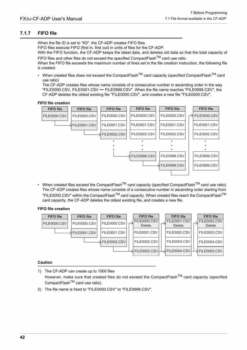
7 Before Programming
7.1 File format available in the CF-ADPFX3U-CF-ADP User's Manual
7.1.7 FIFO file
When the file ID is set to "K0", the CF-ADP creates FIFO files.FIFO files execute FIFO (first in, first out) in units of files for the CF-ADP.With the FIFO function, the CF-ADP keeps the latest data, and deletes old data so that the total capacity of
FIFO files and other files do not exceed the specified CompactFlashTM card use ratio.When the FIFO file exceeds the maximum number of lines set in the file creation instruction, the following fileis created:
• When created files does not exceed the CompactFlashTM card capacity (specified CompactFlashTM card use ratio)The CF-ADP creates files whose name consists of a consecutive number in ascending order in the way "FILE0000.CSV, FILE0001.CSV ••• FILE0999.CSV". When the file name reaches "FILE0999.CSV", the CF-ADP deletes the oldest existing file "FILE0000.CSV", and creates a new file "FILE0000.CSV".
FIFO file creation
• When created files exceed the CompactFlashTM card capacity (specified CompactFlashTM card use ratio)The CF-ADP creates files whose name consists of a consecutive number in ascending order starting from
"FILE0000.CSV" within the CompactFlashTM card capacity. When created files reach the CompactFlashTM card capacity, the CF-ADP deletes the oldest existing file, and creates a new file.
FIFO file creation
Caution
1) The CF-ADP can create up to 1000 files
However, make sure that created files do not exceed the CompactFlashTM card capacity (specified
CompactFlashTM card use ratio).
2) The file name is fixed to "FILE0000.CSV" to "FILE0999.CSV".
FILE0000.CSVFILE0000.CSV
FILE0001.CSV
FILE0002.CSV
FILE0998.CSV
FILE0999.CSV
FIFO file FIFO file
FILE0000.CSV
FIFO file
FILE0000.CSV
FILE0001.CSV
FIFO file
FILE0000.CSV
FILE0001.CSV
FILE0002.CSV
FIFO file
FILE0000.CSV
FILE0001.CSV
FILE0002.CSV
FILE0998.CSV
FILE0999.CSV
FIFO file
FILE0001.CSV
FILE0002.CSV
FILE0998.CSV
FILE0002.CSVDelete
FILE0000.CSVDelete
FILE0001.CSVDelete
FILE0005.CSV
FILE0000.CSV
FILE0001.CSV
FILE0002.CSV
FILE0003.CSV FILE0004.CSV
FIFO file FIFO file
FILE0000.CSV
FIFO file
FILE0000.CSV
FILE0001.CSV
FIFO file
FILE0001.CSV
FILE0002.CSV
FIFO file
FILE0002.CSV
FILE0003.CSV FILE0004.CSV
FIFO file
FILE0003.CSV
42
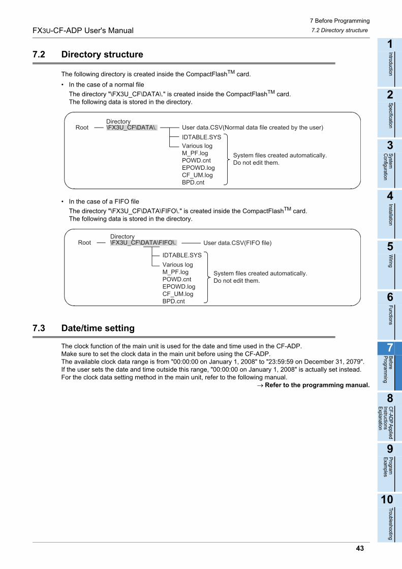
7 Before Programming
7.2 Directory structureFX3U-CF-ADP User's Manual
1
Introduction
2
Specification
3
System
C
onfiguration
4
Installation
5
Wiring
6
Functions
7
Before
Program
ming
8
CF-A
DP
Applied
Instructions E
xplanation
9
Program
E
xamples
10
Troubleshooting
7.2 Directory structure
The following directory is created inside the CompactFlashTM card.
• In the case of a normal file
The directory "\FX3U_CF\DATA\." is created inside the CompactFlashTM card.The following data is stored in the directory.
• In the case of a FIFO file
The directory "\FX3U_CF\DATA\FIFO\." is created inside the CompactFlashTM card.The following data is stored in the directory.
7.3 Date/time setting
The clock function of the main unit is used for the date and time used in the CF-ADP.Make sure to set the clock data in the main unit before using the CF-ADP.The available clock data range is from "00:00:00 on January 1, 2008" to "23:59:59 on December 31, 2079".If the user sets the date and time outside this range, "00:00:00 on January 1, 2008" is actually set instead.For the clock data setting method in the main unit, refer to the following manual.
Refer to the programming manual.
Root \FX3U_CF\DATA\. User data.CSV(Normal data file created by the user)IDTABLE.SYSVarious logM_PF.logPOWD.cntEPOWD.logCF_UM.logBPD.cnt
Directory
System files created automatically.Do not edit them.
Root \FX3U_CF\DATA\FIFO\. User data.CSV(FIFO file)
IDTABLE.SYSVarious logM_PF.logPOWD.cntEPOWD.logCF_UM.logBPD.cnt
Directory
System files created automatically.Do not edit them.
43
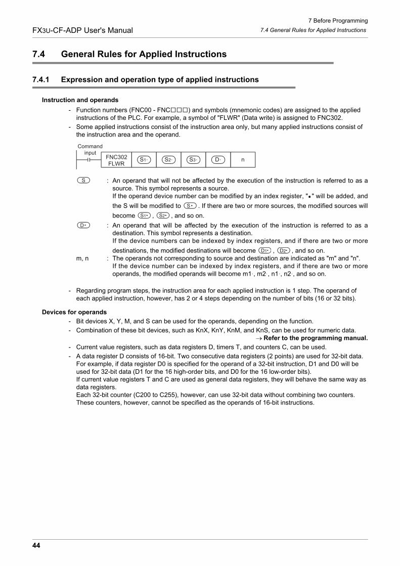
7 Before Programming
7.4 General Rules for Applied InstructionsFX3U-CF-ADP User's Manual
7.4 General Rules for Applied Instructions
7.4.1 Expression and operation type of applied instructions
Instruction and operands
- Function numbers (FNC00 - FNC ) and symbols (mnemonic codes) are assigned to the applied instructions of the PLC. For example, a symbol of "FLWR" (Data write) is assigned to FNC302.
- Some applied instructions consist of the instruction area only, but many applied instructions consist of the instruction area and the operand.
: An operand that will not be affected by the execution of the instruction is referred to as asource. This symbol represents a source.If the operand device number can be modified by an index register, " " will be added, and
the S will be modified to . If there are two or more sources, the modified sources will
become , , and so on.
: An operand that will be affected by the execution of the instruction is referred to as adestination. This symbol represents a destination.If the device numbers can be indexed by index registers, and if there are two or more
destinations, the modified destinations will become , , and so on.m, n : The operands not corresponding to source and destination are indicated as "m" and "n".
If the device number can be indexed by index registers, and if there are two or moreoperands, the modified operands will become m1 , m2 , n1 , n2 , and so on.
- Regarding program steps, the instruction area for each applied instruction is 1 step. The operand of each applied instruction, however, has 2 or 4 steps depending on the number of bits (16 or 32 bits).
Devices for operands
- Bit devices X, Y, M, and S can be used for the operands, depending on the function.
- Combination of these bit devices, such as KnX, KnY, KnM, and KnS, can be used for numeric data.Refer to the programming manual.
- Current value registers, such as data registers D, timers T, and counters C, can be used.
- A data register D consists of 16-bit. Two consecutive data registers (2 points) are used for 32-bit data.For example, if data register D0 is specified for the operand of a 32-bit instruction, D1 and D0 will be used for 32-bit data (D1 for the 16 high-order bits, and D0 for the 16 low-order bits).If current value registers T and C are used as general data registers, they will behave the same way as data registers.Each 32-bit counter (C200 to C255), however, can use 32-bit data without combining two counters. These counters, however, cannot be specified as the operands of 16-bit instructions.
Commandinput
FNC302FLWR
S1 nS2 S3 D
S
S
S1 S2
D
D1 D2
44
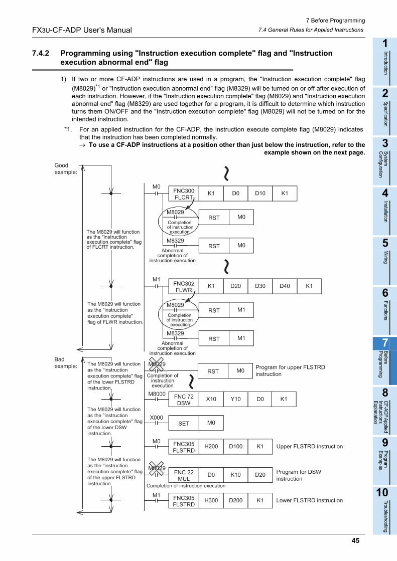
7 Before Programming
7.4 General Rules for Applied InstructionsFX3U-CF-ADP User's Manual
1
Introduction
2
Specification
3
System
C
onfiguration
4
Installation
5
Wiring
6
Functions
7
Before
Program
ming
8
CF-A
DP
Applied
Instructions E
xplanation
9
Program
E
xamples
10
Troubleshooting
7.4.2 Programming using "Instruction execution complete" flag and "Instruction execution abnormal end" flag
1) If two or more CF-ADP instructions are used in a program, the "Instruction execution complete" flag
(M8029)*1 or "Instruction execution abnormal end" flag (M8329) will be turned on or off after execution ofeach instruction. However, if the "Instruction execution complete" flag (M8029) and "Instruction executionabnormal end" flag (M8329) are used together for a program, it is difficult to determine which instructionturns them ON/OFF and the "Instruction execution complete" flag (M8029) will not be turned on for theintended instruction.
*1. For an applied instruction for the CF-ADP, the instruction execute complete flag (M8029) indicatesthat the instruction has been completed normally. To use a CF-ADP instructions at a position other than just below the instruction, refer to the
example shown on the next page.
Badexample:
The M8029 will functionas the "instructionexecution complete" flagof the lower DSWinstruction.
The M8029 will functionas the "instructionexecution complete" flagof the upper FLSTRDinstruction.
The M8029 will functionas the "instructionexecution complete" flagof the lower FLSTRDinstruction.
RST M0
FNC 22MUL
D0 K10 D20
M8000X10 Y10 D0
Completion ofinstructionexecution
FNC 72DSW
K1
X000M0SET
M0H200 D100 K1FNC305
FLSTRD
M8029
M8029
Completion of instruction execution
M1H300 D200 K1FNC305
FLSTRD
Program for upper FLSTRDinstruction
Program for DSWinstruction
Upper FLSTRD instruction
Lower FLSTRD instruction
M0FNC300FLCRT
K1 D0 D10 K1
K1
M0M8029
Completion of instruction
execution
M1FNC302FLWR
K1 D20 D30
RST M1M8029
M8329The M8029 will functionas the "instructionexecution complete" flagof FLCRT instruction.
The M8029 will functionas the "instructionexecution complete"flag of FLWR instruction.
Goodexample:
Abnormalcompletion of
instruction execution
M0
D40
RST
RST
Completionof instruction
execution
M8329M1RST
Abnormalcompletion of
instruction execution
45
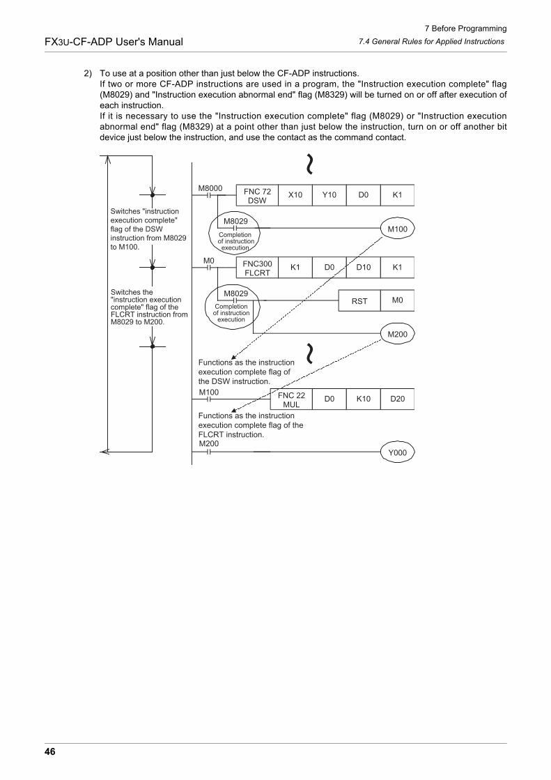
7 Before Programming
7.4 General Rules for Applied InstructionsFX3U-CF-ADP User's Manual
2) To use at a position other than just below the CF-ADP instructions.If two or more CF-ADP instructions are used in a program, the "Instruction execution complete" flag(M8029) and "Instruction execution abnormal end" flag (M8329) will be turned on or off after execution ofeach instruction.If it is necessary to use the "Instruction execution complete" flag (M8029) or "Instruction executionabnormal end" flag (M8329) at a point other than just below the instruction, turn on or off another bitdevice just below the instruction, and use the contact as the command contact.
M8000 FNC 72DSW
X10 Y10 D0 K1
FNC 22MUL
D0 K10 D20
M8029Completion
of instructionexecution
M0 FNC300FLCRT
K1 D0 D10
M8029Completion
of instructionexecution
Switches "instructionexecution complete"flag of the DSWinstruction from M8029to M100.
M100
M200
Switches the"instruction executioncomplete" flag of theFLCRT instruction fromM8029 to M200.
M100
Functions as the instructionexecution complete flag ofthe DSW instruction.
RST M0
M200
Functions as the instructionexecution complete flag of theFLCRT instruction.
Y000
K1
46
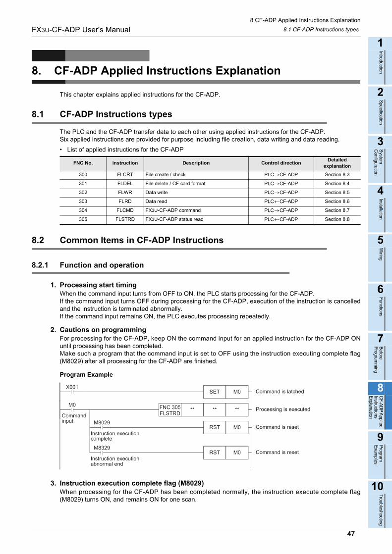
8 CF-ADP Applied Instructions Explanation
8.1 CF-ADP Instructions typesFX3U-CF-ADP User's Manual
1
Introduction
2
Specification
3
System
C
onfiguration
4
Installation
5
Wiring
6
Functions
7
Before
Program
ming
8
CF-A
DP
Applied
Instructions E
xplanation
9
Program
E
xamples
10
Troubleshooting
8. CF-ADP Applied Instructions Explanation
This chapter explains applied instructions for the CF-ADP.
8.1 CF-ADP Instructions types
The PLC and the CF-ADP transfer data to each other using applied instructions for the CF-ADP.Six applied instructions are provided for purpose including file creation, data writing and data reading.
• List of applied instructions for the CF-ADP
8.2 Common Items in CF-ADP Instructions
8.2.1 Function and operation
1. Processing start timingWhen the command input turns from OFF to ON, the PLC starts processing for the CF-ADP.If the command input turns OFF during processing for the CF-ADP, execution of the instruction is cancelledand the instruction is terminated abnormally.If the command input remains ON, the PLC executes processing repeatedly.
2. Cautions on programmingFor processing for the CF-ADP, keep ON the command input for an applied instruction for the CF-ADP ONuntil processing has been completed.Make such a program that the command input is set to OFF using the instruction executing complete flag(M8029) after all processing for the CF-ADP are finished.
Program Example
3. Instruction execution complete flag (M8029)When processing for the CF-ADP has been completed normally, the instruction execute complete flag(M8029) turns ON, and remains ON for one scan.
FNC No. instruction Description Control directionDetailed
explanation
300 FLCRT File create / check PLC CF-ADP Section 8.3
301 FLDEL File delete / CF card format PLC CF-ADP Section 8.4
302 FLWR Data write PLC CF-ADP Section 8.5
303 FLRD Data read PLC CF-ADP Section 8.6
304 FLCMD FX3U-CF-ADP command PLC CF-ADP Section 8.7
305 FLSTRD FX3U-CF-ADP status read PLC CF-ADP Section 8.8
X001SET M0 Command is latched
RST M0M8029
Instruction executioncomplete
** **FNC 305FLSTRD
**M0
Processing is executed
Command is reset
Commandinput
RST M0M8329
Instruction executionabnormal end
Command is reset
47
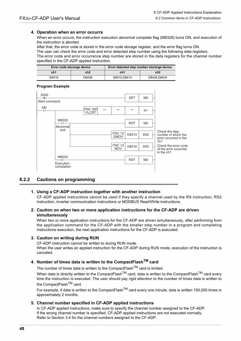
8 CF-ADP Applied Instructions Explanation
8.2 Common Items in CF-ADP InstructionsFX3U-CF-ADP User's Manual
4. Operation when an error occurrsWhen an error occurs, the instruction execution abnormal complete flag (M8329) turns ON, and execution ofthe instruction is aborted.After that, the error code is stored in the error code storage register, and the error flag turns ON.The user can check the error code and error detected step number using the following data registers.The error code and error occurrence step number are stored in the data registers for the channel numberspecified in the CF-ADP applied instruction.
Program Example
8.2.2 Cautions on programming
1. Using a CF-ADP instruction together with another instructionCF-ADP applied instructions cannot be used if they specify a channel used by the RS instruction, RS2instruction, inverter communication instructions or MODBUS Read/Write instructions.
2. Caution on when two or more application instructions for the CF-ADP are driven simultaneouslyWhen two or more application instructions for the CF-ADP are driven simultaneously, after performing fromthe application command for the CF-ADP with the smaller step number in a program and completinginstructions execution, the next application instructions for the CF-ADP is executed.
3. Caution on writing during RUNCF-ADP instruction cannot be written to during RUN mode.When the user writes an applied instruction for the CF-ADP during RUN mode, execution of the instruction iscanceled.
4. Number of times data is written to the CompactFlashTM card
The number of times data is written to the CompactFlashTM card is limited.
When data is directly written to the CompactFlashTM card, data is written to the CompactFlashTM card everytime the instruction is executed. The user should pay rigid attention to the number of times data is written to
the CompactFlashTM card.
For example, if data is written to the CompactFlashTM card every one minute, data is written 100,000 times inapproximately 2 months.
5. Channel number specified in CF-ADP applied instructionsIn CF-ADP applied instructions, make sure to specify the channel number assigned to the CF-ADP.If the wrong channel number is specified, CF-ADP applied instructions are not executed normally.Refer to Section 3.4 for the channel numbers assigned to the CF-ADP.
Error code storange device Error detected step number storange device
ch1 ch2 ch1 ch2
D8418 D8438 D8415,D8414 D8435,D8434
FNC 12MOV
SET M0Start command
M8329
D8414 D50FNC 12DMOV
RST M0
** K1FNC 300FLCRT
** **M0
Check the stepnumber in which theerror occurred in thech1.
D8418 D53 Check the error codeof the error occurredin the ch1.
X000
M8029RST M0
Executioncompletion
Abnormalend
48
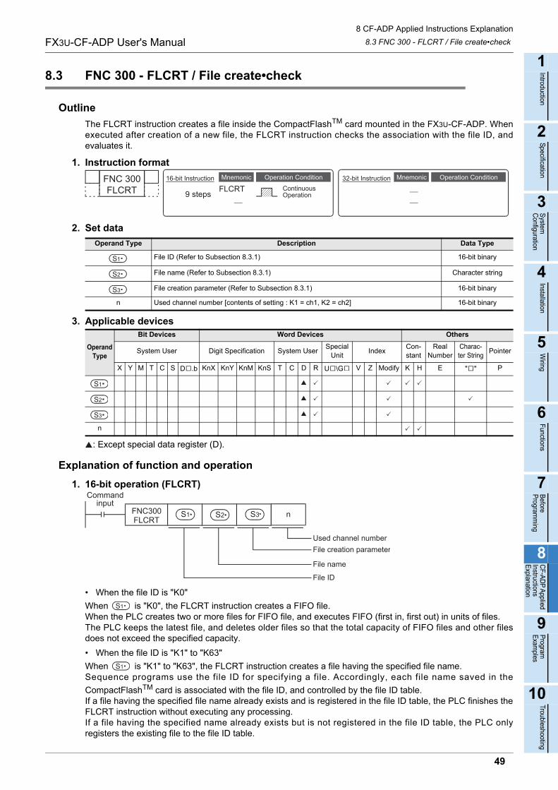
8 CF-ADP Applied Instructions Explanation
8.3 FNC 300 - FLCRT / File create•checkFX3U-CF-ADP User's Manual
1
Introduction
2
Specification
3
System
C
onfiguration
4
Installation
5
Wiring
6
Functions
7
Before
Program
ming
8
CF-A
DP
Applied
Instructions E
xplanation
9
Program
E
xamples
10
Troubleshooting
8.3 FNC 300 - FLCRT / File create•check
Outline
The FLCRT instruction creates a file inside the CompactFlashTM card mounted in the FX3U-CF-ADP. Whenexecuted after creation of a new file, the FLCRT instruction checks the association with the file ID, andevaluates it.
1. Instruction format
2. Set data
3. Applicable devices
: Except special data register (D).
Explanation of function and operation
1. 16-bit operation (FLCRT)
• When the file ID is "K0"
When is "K0", the FLCRT instruction creates a FIFO file.When the PLC creates two or more files for FIFO file, and executes FIFO (first in, first out) in units of files.The PLC keeps the latest file, and deletes older files so that the total capacity of FIFO files and other filesdoes not exceed the specified capacity.
• When the file ID is "K1" to "K63"
When is "K1" to "K63", the FLCRT instruction creates a file having the specified file name.Sequence programs use the file ID for specifying a file. Accordingly, each file name saved in the
CompactFlashTM card is associated with the file ID, and controlled by the file ID table.If a file having the specified file name already exists and is registered in the file ID table, the PLC finishes theFLCRT instruction without executing any processing.If a file having the specified name already exists but is not registered in the file ID table, the PLC onlyregisters the existing file to the file ID table.
Operand Type Description Data Type
File ID (Refer to Subsection 8.3.1) 16-bit binary
File name (Refer to Subsection 8.3.1) Character string
File creation parameter (Refer to Subsection 8.3.1) 16-bit binary
n Used channel number [contents of setting : K1 = ch1, K2 = ch2] 16-bit binary
Operand Type
Bit Devices Word Devices Others
System User Digit Specification System UserSpecial
UnitIndex
Con-stant
Real Number
Charac-ter String
Pointer
X Y M T C S D .b KnX KnY KnM KnS T C D R U \G V Z Modify K H E " " P
n
FNC 300FLCRT
Mnemonic Operation Condition16-bit Instruction
9 steps FLCRTMnemonic Operation Condition
ContinuousOperation
32-bit Instruction
S1
S2
S3
S1
S2
S3
FNC300FLCRT
n
Commandinput
S1 S2 S3
File ID
Used channel numberFile creation parameter
File name
S1
S1
49
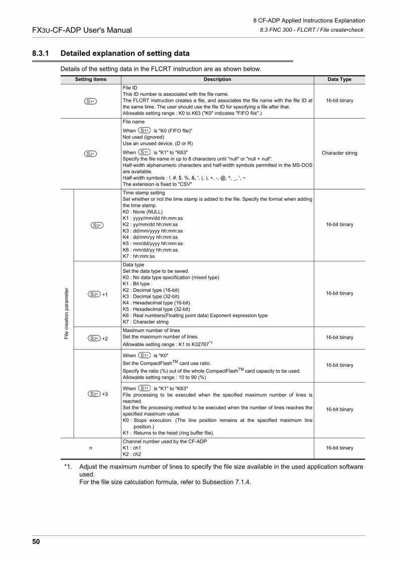
8 CF-ADP Applied Instructions Explanation
8.3 FNC 300 - FLCRT / File create•checkFX3U-CF-ADP User's Manual
8.3.1 Detailed explanation of setting data
Details of the setting data in the FLCRT instruction are as shown below.
*1. Adjust the maximum number of lines to specify the file size available in the used application softwareused.For the file size calculation formula, refer to Subsection 7.1.4.
Setting items Description Data Type
File IDThis ID number is associated with the file name.The FLCRT instruction creates a file, and associates the file name with the file ID atthe same time. The user should use the file ID for specifying a file after that.Allowable setting range : K0 to K63 ("K0" indicates "FIFO file".)
16-bit binary
File name
When is "K0 (FIFO file)"Not used (ignored)Use an unused device. (D or R)
When is "K1" to "K63"Specify the file name in up to 8 characters until "null" or "null + null".Half-width alphanumeric characters and half-width symbols permitted in the MS-DOSare available.Half-width symbols : !, #, $, %, &, ', (, ), +, -, @, ^, _, ', ~The extension is fixed to "CSV"
Character string
File
cre
atio
n p
aram
ete
r
Time stamp settingSet whether or not the time stamp is added to the file. Specify the format when addingthe time stamp.K0 : None (NULL)K1 : yyyy/mm/dd hh:mm:ssK2 : yy/mm/dd hh:mm:ssK3 : dd/mm/yyyy hh:mm:ssK4 : dd/mm/yy hh:mm:ssK5 : mm/dd/yyyy hh:mm:ssK6 : mm/dd/yy hh:mm:ssK7 : hh:mm:ss
16-bit binary
+1
Data typeSet the data type to be saved.K0 : No data type specification (mixed type)K1 : Bit typeK2 : Decimal type (16-bit)K3 : Decimal type (32-bit)K4 : Hexadecimal type (16-bit)K5 : Hexadecimal type (32-bit)K6 : Real numbers(Floating point data) Exponent expression typeK7 : Character string
16-bit binary
+2
Maximum number of linesSet the maximum number of lines.
Allowable setting range : K1 to K32767*116-bit binary
+3
When is "K0"
Set the CompactFlashTM card use ratio.
Specify the ratio (%) out of the whole CompactFlashTM card capacity to be used.Allowable setting range : 10 to 90 (%)
16-bit binary
When is "K1" to "K63"File processing to be executed when the specified maximum number of lines isreached.Set the file processing method to be executed when the number of lines reaches thespecified maximum value.K0 : Stops execution. (The line position remains at the specified maximum line
position.)K1 : Returns to the head (ring buffer file).
16-bit binary
nChannel number used by the CF-ADPK1 : ch1K2 : ch2
16-bit binary
S1
S2
S1
S1
S3
S3
S3
S3
S1
S1
50
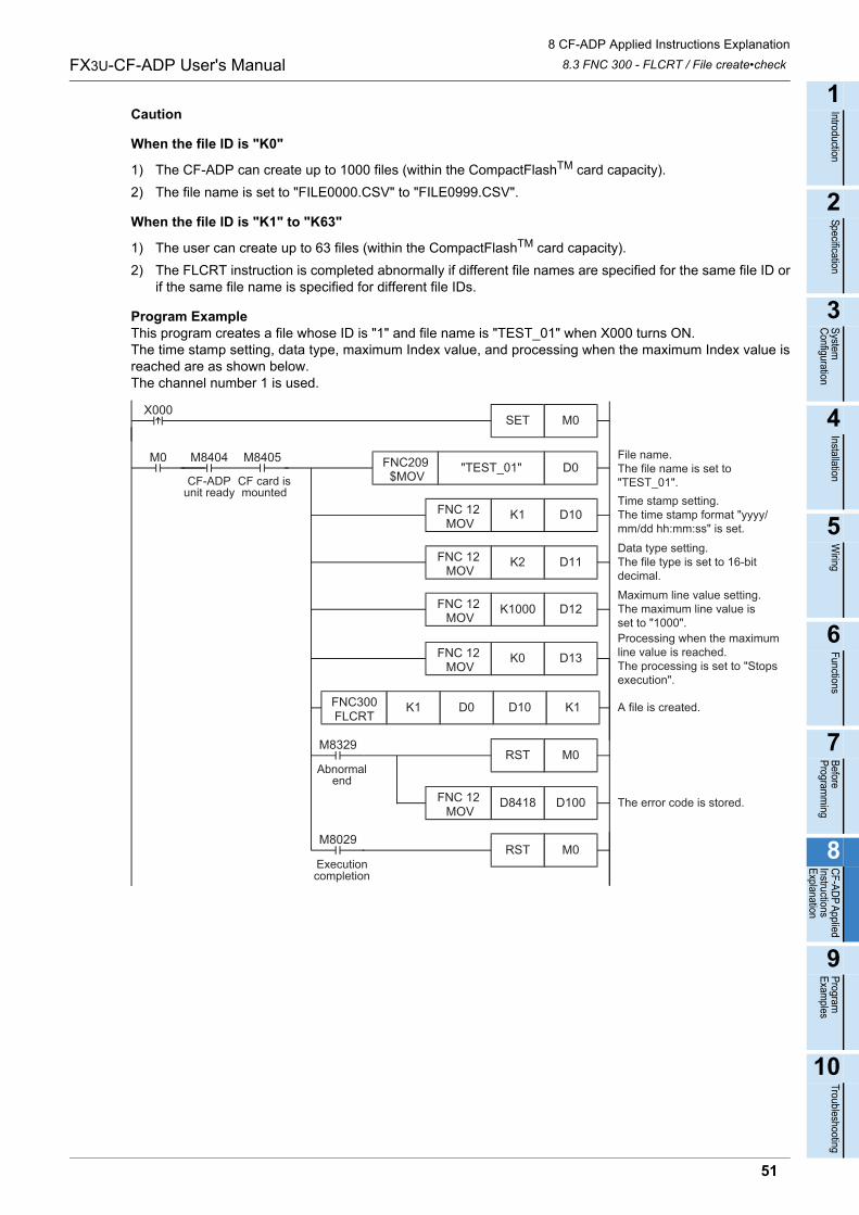
8 CF-ADP Applied Instructions Explanation
8.3 FNC 300 - FLCRT / File create•checkFX3U-CF-ADP User's Manual
1
Introduction
2
Specification
3
System
C
onfiguration
4
Installation
5
Wiring
6
Functions
7
Before
Program
ming
8
CF-A
DP
Applied
Instructions E
xplanation
9
Program
E
xamples
10
Troubleshooting
Caution
When the file ID is "K0"
1) The CF-ADP can create up to 1000 files (within the CompactFlashTM card capacity).
2) The file name is set to "FILE0000.CSV" to "FILE0999.CSV".
When the file ID is "K1" to "K63"
1) The user can create up to 63 files (within the CompactFlashTM card capacity).
2) The FLCRT instruction is completed abnormally if different file names are specified for the same file ID orif the same file name is specified for different file IDs.
Program ExampleThis program creates a file whose ID is "1" and file name is "TEST_01" when X000 turns ON.The time stamp setting, data type, maximum Index value, and processing when the maximum Index value isreached are as shown below.The channel number 1 is used.
Time stamp setting.The time stamp format "yyyy/mm/dd hh:mm:ss" is set.
D11K2
D12K1000FNC 12 MOV
Data type setting.The file type is set to 16-bitdecimal.
Processing when the maximumline value is reached.The processing is set to "Stopsexecution".
A file is created.
Maximum line value setting.The maximum line value isset to "1000".
D0"TEST_01"FNC209 $MOV
M8405
CF card ismounted
M0 M8404
CF-ADPunit ready
File name.The file name is set to"TEST_01".
FNC 12 MOV
D10K1FNC 12 MOV
D13K0FNC 12 MOV
K1D10D0FNC300FLCRT
K1
D100D8418 The error code is stored.FNC 12 MOV
M0RST
M0RST
M8029
M8329
M0SETX000
Executioncompletion
Abnormalend
51
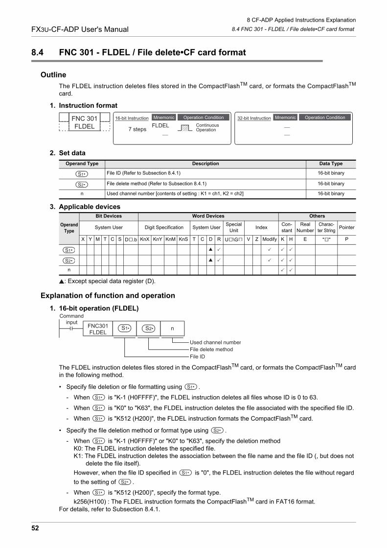
8 CF-ADP Applied Instructions Explanation
8.4 FNC 301 - FLDEL / File delete•CF card formatFX3U-CF-ADP User's Manual
8.4 FNC 301 - FLDEL / File delete•CF card format
Outline
The FLDEL instruction deletes files stored in the CompactFlashTM card, or formats the CompactFlashTM
card.
1. Instruction format
2. Set data
3. Applicable devices
: Except special data register (D).
Explanation of function and operation
1. 16-bit operation (FLDEL)
The FLDEL instruction deletes files stored in the CompactFlashTM card, or formats the CompactFlashTM cardin the following method.
• Specify file deletion or file formatting using .
- When is "K-1 (H0FFFF)", the FLDEL instruction deletes all files whose ID is 0 to 63.
- When is "K0" to "K63", the FLDEL instruction deletes the file associated with the specified file ID.
- When is "K512 (H200)", the FLDEL instruction formats the CompactFlashTM card.
• Specify the file deletion method or format type using .
- When is "K-1 (H0FFFF)" or "K0" to "K63", specify the deletion methodK0: The FLDEL instruction deletes the specified file.K1: The FLDEL instruction deletes the association between the file name and the file ID (, but does not delete the file itself).
However, when the file ID specified in is "0", the FLDEL instruction deletes the file without regard
to the setting of .
- When is "K512 (H200)", specify the format type.
k256(H100) : The FLDEL instruction formats the CompactFlashTM card in FAT16 format.For details, refer to Subsection 8.4.1.
Operand Type Description Data Type
File ID (Refer to Subsection 8.4.1) 16-bit binary
File delete method (Refer to Subsection 8.4.1) 16-bit binary
n Used channel number [contents of setting : K1 = ch1, K2 = ch2] 16-bit binary
Operand Type
Bit Devices Word Devices Others
System User Digit Specification System UserSpecial
UnitIndex
Con-stant
Real Number
Charac-ter String
Pointer
X Y M T C S D .b KnX KnY KnM KnS T C D R U \G V Z Modify K H E " " P
n
FNC 301FLDEL
Mnemonic Operation Condition16-bit Instruction
7 steps FLDELMnemonic Operation Condition
ContinuousOperation
32-bit Instruction
S1
S2
S1
S2
S1 S2
Commandinput
FNC301FLDEL
n
Used channel numberFile delete methodFile ID
S1
S1
S1
S1
S2
S1
S1
S2
S1
52
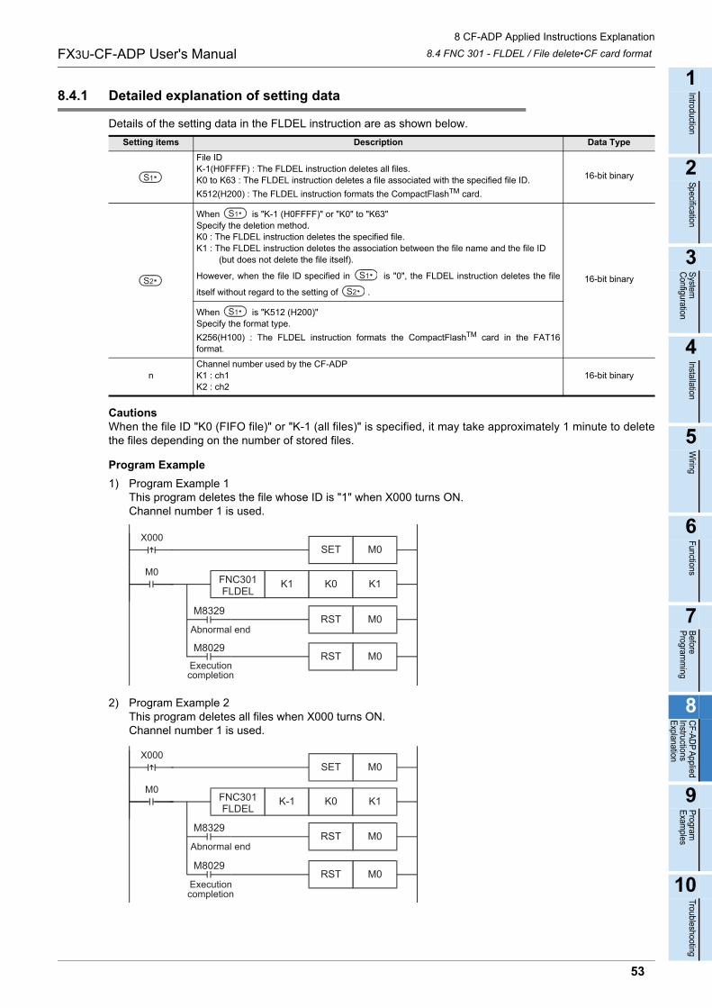
8 CF-ADP Applied Instructions Explanation
8.4 FNC 301 - FLDEL / File delete•CF card formatFX3U-CF-ADP User's Manual
1
Introduction
2
Specification
3
System
C
onfiguration
4
Installation
5
Wiring
6
Functions
7
Before
Program
ming
8
CF-A
DP
Applied
Instructions E
xplanation
9
Program
E
xamples
10
Troubleshooting
8.4.1 Detailed explanation of setting data
Details of the setting data in the FLDEL instruction are as shown below.
CautionsWhen the file ID "K0 (FIFO file)" or "K-1 (all files)" is specified, it may take approximately 1 minute to deletethe files depending on the number of stored files.
Program Example
1) Program Example 1This program deletes the file whose ID is "1" when X000 turns ON.Channel number 1 is used.
2) Program Example 2This program deletes all files when X000 turns ON.Channel number 1 is used.
Setting items Description Data Type
File IDK-1(H0FFFF) : The FLDEL instruction deletes all files.K0 to K63 : The FLDEL instruction deletes a file associated with the specified file ID.
K512(H200) : The FLDEL instruction formats the CompactFlashTM card.
16-bit binary
When is "K-1 (H0FFFF)" or "K0" to "K63"Specify the deletion method.K0 : The FLDEL instruction deletes the specified file.K1 : The FLDEL instruction deletes the association between the file name and the file ID (but does not delete the file itself).
However, when the file ID specified in is "0", the FLDEL instruction deletes the file
itself without regard to the setting of .
16-bit binary
When is "K512 (H200)"Specify the format type.
K256(H100) : The FLDEL instruction formats the CompactFlashTM card in the FAT16format.
nChannel number used by the CF-ADPK1 : ch1K2 : ch2
16-bit binary
S1
S2
S1
S1
S2
S1
X000M0SET
FNC301FLDEL
K1 K0 K1M0
M8029
Executioncompletion
M0RST
M8329
Abnormal endM0RST
X000M0SET
FNC301FLDEL
K-1 K0 K1M0
M8029
Executioncompletion
M0RST
M8329
Abnormal endM0RST
53
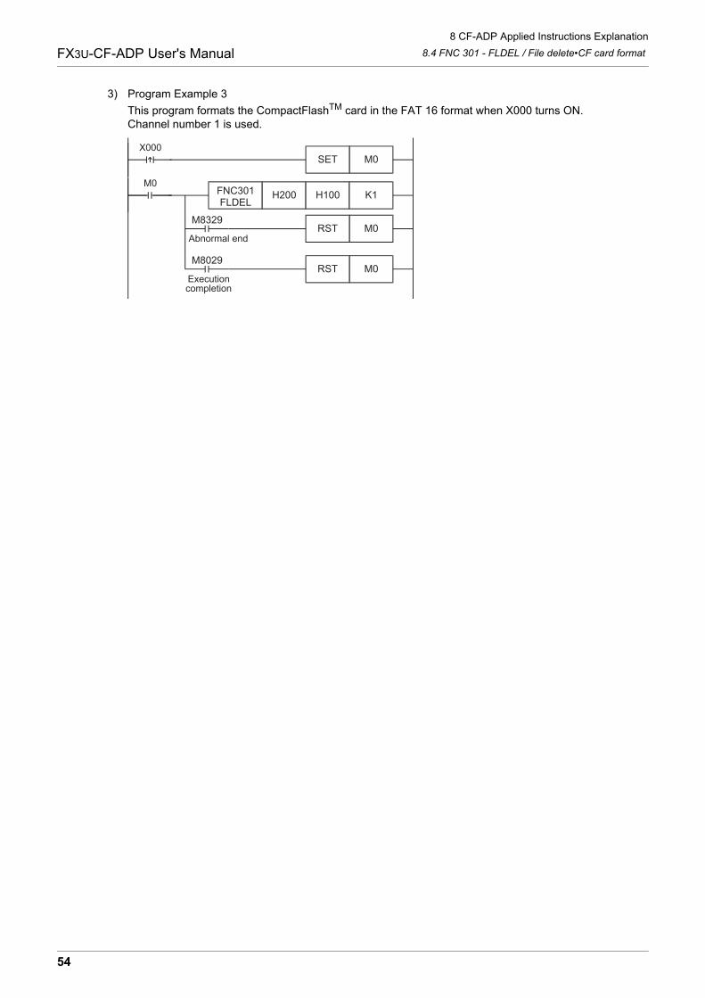
8 CF-ADP Applied Instructions Explanation
8.4 FNC 301 - FLDEL / File delete•CF card formatFX3U-CF-ADP User's Manual
3) Program Example 3
This program formats the CompactFlashTM card in the FAT 16 format when X000 turns ON.Channel number 1 is used.
X000M0SET
FNC301FLDEL
H200 H100 K1M0
M8029
Executioncompletion
M0RST
M8329
Abnormal endM0RST
54
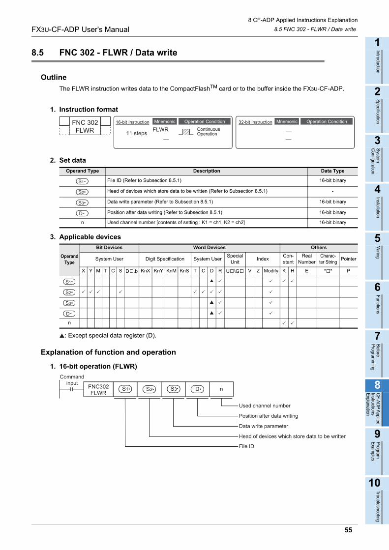
8 CF-ADP Applied Instructions Explanation
8.5 FNC 302 - FLWR / Data writeFX3U-CF-ADP User's Manual
1
Introduction
2
Specification
3
System
C
onfiguration
4
Installation
5
Wiring
6
Functions
7
Before
Program
ming
8
CF-A
DP
Applied
Instructions E
xplanation
9
Program
E
xamples
10
Troubleshooting
8.5 FNC 302 - FLWR / Data write
Outline
The FLWR instruction writes data to the CompactFlashTM card or to the buffer inside the FX3U-CF-ADP.
1. Instruction format
2. Set data
3. Applicable devices
: Except special data register (D).
Explanation of function and operation
1. 16-bit operation (FLWR)
Operand Type Description Data Type
File ID (Refer to Subsection 8.5.1) 16-bit binary
Head of devices which store data to be written (Refer to Subsection 8.5.1) -
Data write parameter (Refer to Subsection 8.5.1) 16-bit binary
Position after data writing (Refer to Subsection 8.5.1) 16-bit binary
n Used channel number [contents of setting : K1 = ch1, K2 = ch2] 16-bit binary
Operand Type
Bit Devices Word Devices Others
System User Digit Specification System UserSpecial
UnitIndex
Con-stant
Real Number
Charac-ter String
Pointer
X Y M T C S D .b KnX KnY KnM KnS T C D R U \G V Z Modify K H E " " P
n
FNC 302FLWR
Mnemonic Operation Condition16-bit Instruction
11 steps FLWRMnemonic Operation Condition
ContinuousOperation
32-bit Instruction
S1
S2
S3
D
S1
S2
S3
D
DS1 S2 S3
Commandinput FNC302
FLWRn
Head of devices which store data to be written
Used channel number
Position after data writing
Data write parameter
File ID
55
8 CF-ADP Applied Instructions Explanation
8.5 FNC 302 - FLWR / Data writeFX3U-CF-ADP User's Manual
The FLWR instruction writes data specified by the device to a file stored in the CompactFlashTM cardspecified by the file ID or to the buffer inside the CF-ADP. The FLWR instruction can overwrite data in the line
position specified by the device +1, and can write additional data (K-1). When the writing destination isthe buffer inside the CF-ADP, the FLWR instruction can only execute additional writing. When writing iscompleted, the line position and column position after writing are as follows.
• When data in 1 line is written additionally
- Line position after writing : Written line position + K1
- Column position after writing : K1
• When a line having existing data is overwritten
- Line position after writing : Written line position if data is not written to the final column position of the specified line positionLine position next to the written line position if data is written to the final column position of the line
- Column position after writing: Column position next to the final written data point K1 if data is written to the final data point in the line "K1" if data is written to the final data point in the line
Both additional writing and overwriting are executed to the maximum number of lines specified during filecreation. If data is written up to the final column position, the line position after writing varies depending on thefile type and setting.
• When the processing is stopped by the maximum line position in a normal fileLine position value after writing = Maximum line position + K1K-32768 when the maximum line position is "K32767"
• In the case of a normal file in which processing returns to the head of the file from the end of the file (ring buffer file)Line position after writing = K1
• In the case of FIFO fileLine position after writing = K1
In either case, the column position after writing is "K1".
S2
S3
56
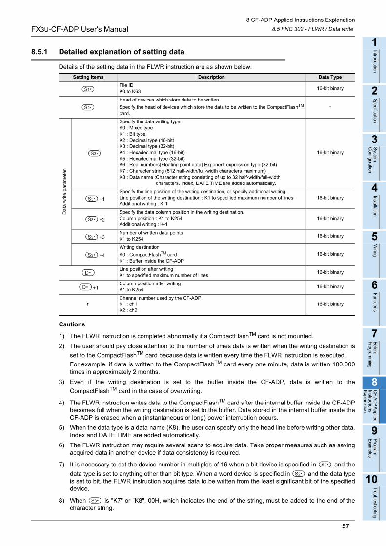
8 CF-ADP Applied Instructions Explanation
8.5 FNC 302 - FLWR / Data writeFX3U-CF-ADP User's Manual
1
Introduction
2
Specification
3
System
C
onfiguration
4
Installation
5
Wiring
6
Functions
7
Before
Program
ming
8
CF-A
DP
Applied
Instructions E
xplanation
9
Program
E
xamples
10
Troubleshooting
8.5.1 Detailed explanation of setting data
Details of the setting data in the FLWR instruction are as shown below.
Cautions
1) The FLWR instruction is completed abnormally if a CompactFlashTM card is not mounted.
2) The user should pay close attention to the number of times data is written when the writing destination is
set to the CompactFlashTM card because data is written every time the FLWR instruction is executed.
For example, if data is written to the CompactFlashTM card every one minute, data is written 100,000times in approximately 2 months.
3) Even if the writing destination is set to the buffer inside the CF-ADP, data is written to the
CompactFlashTM card in the case of overwriting.
4) The FLWR instruction writes data to the CompactFlashTM card after the internal buffer inside the CF-ADPbecomes full when the writing destination is set to the buffer. Data stored in the internal buffer inside theCF-ADP is erased when a (instantaneous or long) power interruption occurs.
5) When the data type is a data name (K8), the user can specify only the head line before writing other data.Index and DATE TIME are added automatically.
6) The FLWR instruction may require several scans to acquire data. Take proper measures such as savingacquired data in another device if data consistency is required.
7) It is necessary to set the device number in multiples of 16 when a bit device is specified in and the
data type is set to anything other than bit type. When a word device is specified in and the data typeis set to bit, the FLWR instruction acquires data to be written from the least significant bit of the specifieddevice.
8) When is "K7" or "K8", 00H, which indicates the end of the string, must be added to the end of thecharacter string.
Setting items Description Data Type
File IDK0 to K63
16-bit binary
Head of devices which store data to be written.
Specify the head of devices which store the data to be written to the CompactFlashTM
card.
-
Da
ta w
rite
para
met
er
Specify the data writing typeK0 : Mixed typeK1 : Bit typeK2 : Decimal type (16-bit)K3 : Decimal type (32-bit)K4 : Hexadecimal type (16-bit)K5 : Hexadecimal type (32-bit)K6 : Real numbers(Floating point data) Exponent expression type (32-bit)K7 : Character string (512 half-width/full-width characters maximum)K8 : Data name :Character string consisting of up to 32 half-width/full-width characters. Index, DATE TIME are added automatically.
16-bit binary
+1
Specify the line position of the writing destination, or specify additional writing.Line position of the writing destination : K1 to specified maximum number of linesAdditional writing : K-1
16-bit binary
+2
Specify the data column position in the writing destination.Column position : K1 to K254Additional writing : K-1
16-bit binary
+3Number of written data pointsK1 to K254
16-bit binary
+4
Writing destination
K0 : CompactFlashTM cardK1 : Buffer inside the CF-ADP
16-bit binary
Line position after writingK1 to specified maximum number of lines
16-bit binary
+1Column position after writingK1 to K254
16-bit binary
nChannel number used by the CF-ADPK1 : ch1K2 : ch2
16-bit binary
S1
S2
S3
S3
S3
S3
S3
D
D
S2
S2
S3
57
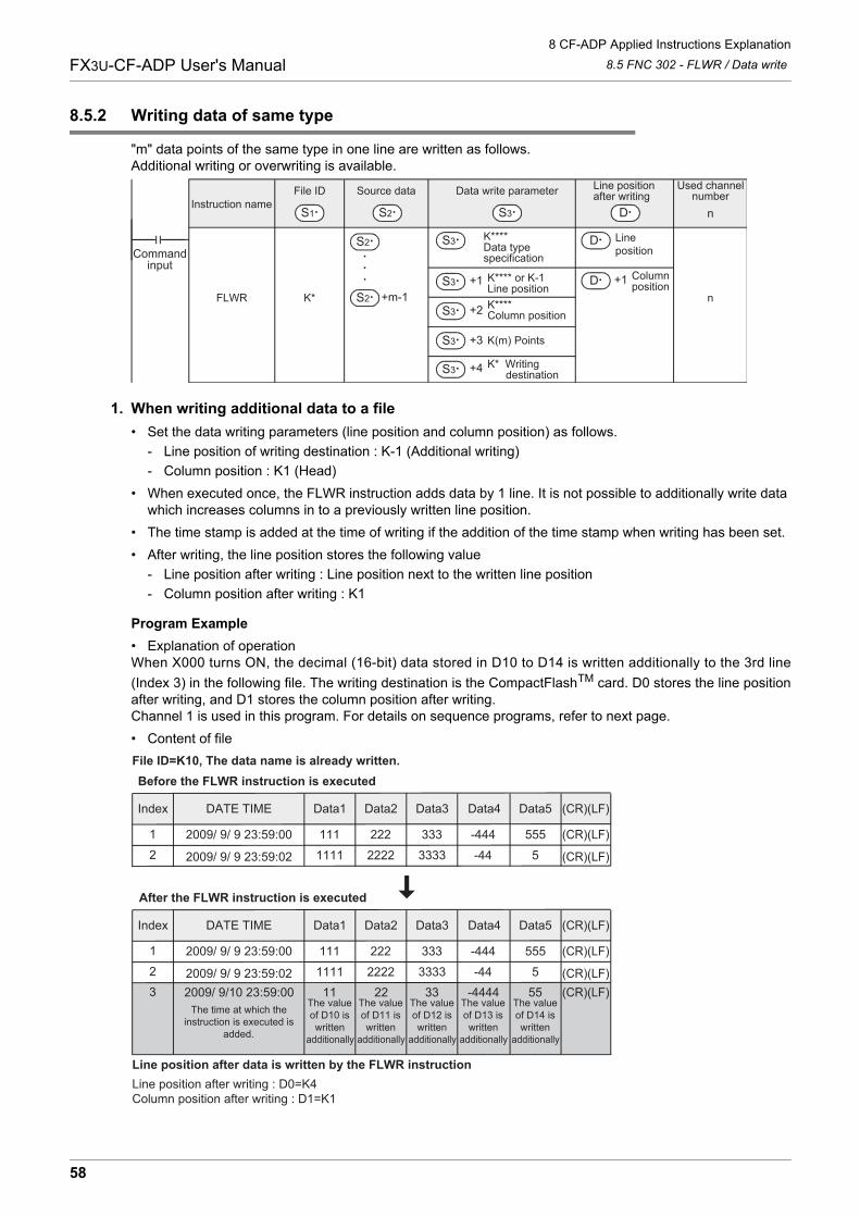
8 CF-ADP Applied Instructions Explanation
8.5 FNC 302 - FLWR / Data writeFX3U-CF-ADP User's Manual
8.5.2 Writing data of same type
"m" data points of the same type in one line are written as follows.Additional writing or overwriting is available.
1. When writing additional data to a file
• Set the data writing parameters (line position and column position) as follows.
- Line position of writing destination : K-1 (Additional writing)
- Column position : K1 (Head)
• When executed once, the FLWR instruction adds data by 1 line. It is not possible to additionally write data which increases columns in to a previously written line position.
• The time stamp is added at the time of writing if the addition of the time stamp when writing has been set.
• After writing, the line position stores the following value
- Line position after writing : Line position next to the written line position
- Column position after writing : K1
Program Example
• Explanation of operationWhen X000 turns ON, the decimal (16-bit) data stored in D10 to D14 is written additionally to the 3rd line
(Index 3) in the following file. The writing destination is the CompactFlashTM card. D0 stores the line positionafter writing, and D1 stores the column position after writing.Channel 1 is used in this program. For details on sequence programs, refer to next page.
• Content of file
Instruction name
FLWR K*
K****Data typespecification
Line position
n
Source data Data write parameter
S3S1
File ID Line position after writing
D
Used channelnumber
K**** or K-1Line positionK****Column position
K(m) Points
Columnposition
D
S2
S2
S2
+m-1
S3
S3 +1
S3 +2
S3 +3
S3 +4
D +1
K* Writing destination
Commandinput
n
DATE TIMEIndex Data1 (CR)(LF)Data5Data4Data3Data2
1111
22009/ 9/ 9 23:59:00 222 333 -444 555 (CR)(LF)
1111 2222 3333 -44 52009/ 9/ 9 23:59:02 (CR)(LF)
DATE TIMEIndex Data1 (CR)(LF)Data5Data4Data3Data2
1111
23
2009/ 9/ 9 23:59:00 222 333 -444 555 (CR)(LF)
1111 2222 3333 -44 511 22 33 -4444 55
2009/ 9/ 9 23:59:022009/ 9/10 23:59:00
(CR)(LF)(CR)(LF)
File ID=K10, The data name is already written.
The time at which theinstruction is executed is
added.
The valueof D10 iswritten
additionally.
The valueof D11 iswritten
additionally.
The valueof D12 iswritten
additionally.
The valueof D13 iswritten
additionally.
The valueof D14 iswritten
additionally.
Line position after writing : D0=K4 Column position after writing : D1=K1
Line position after data is written by the FLWR instruction
After the FLWR instruction is executed
Before the FLWR instruction is executed
58
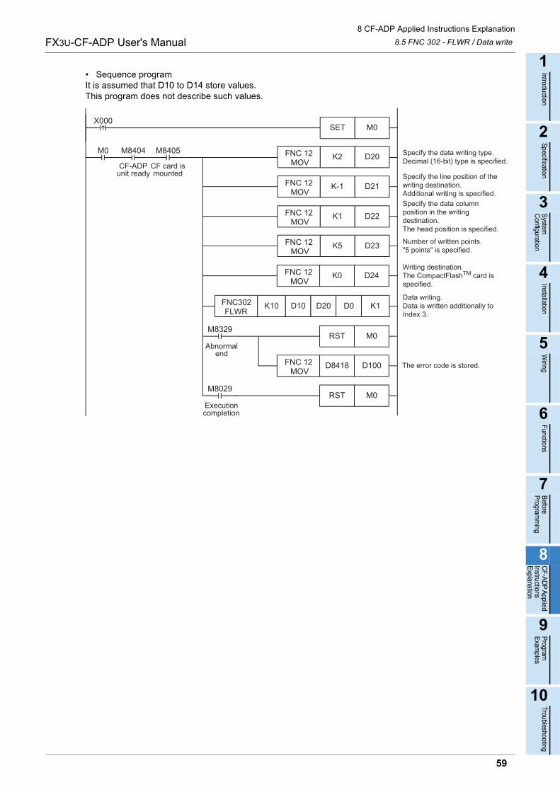
8 CF-ADP Applied Instructions Explanation
8.5 FNC 302 - FLWR / Data writeFX3U-CF-ADP User's Manual
1
Introduction
2
Specification
3
System
C
onfiguration
4
Installation
5
Wiring
6
Functions
7
Before
Program
ming
8
CF-A
DP
Applied
Instructions E
xplanation
9
Program
E
xamples
10
Troubleshooting
• Sequence programIt is assumed that D10 to D14 store values.This program does not describe such values.
Specify the line position of thewriting destination.Additional writing is specified.
D22K1
D23K5FNC 12 MOV
Specify the data columnposition in the writingdestination.The head position is specified.
Number of written points."5 points" is specified.
M8405
CF card ismounted
M0 M8404
CF-ADPunit ready
Specify the data writing type.Decimal (16-bit) type is specified.
FNC 12 MOV
D21K-1
D20K2FNC 12 MOV
FNC 12 MOV
M0SETX000
D24K0FNC 12 MOV
Writing destination.The CompactFlashTM card is specified.
D100D8418 The error code is stored.FNC 12 MOV
M0RST
M0RST
M8029
M8329
Executioncompletion
Abnormalend
Data writing.Data is written additionally toIndex 3.
FNC302FLWR
K10 D10 D20 D0 K1
59
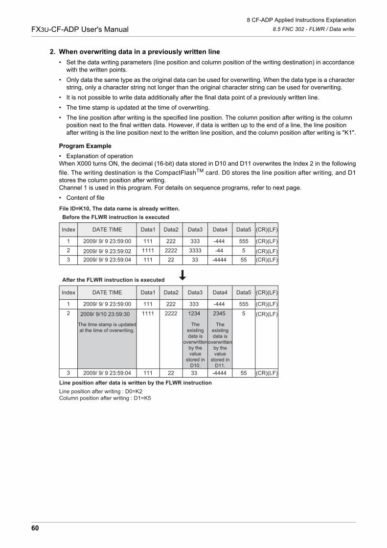
8 CF-ADP Applied Instructions Explanation
8.5 FNC 302 - FLWR / Data writeFX3U-CF-ADP User's Manual
2. When overwriting data in a previously written line
• Set the data writing parameters (line position and column position of the writing destination) in accordance with the written points.
• Only data the same type as the original data can be used for overwriting. When the data type is a character string, only a character string not longer than the original character string can be used for overwriting.
• It is not possible to write data additionally after the final data point of a previously written line.
• The time stamp is updated at the time of overwriting.
• The line position after writing is the specified line position. The column position after writing is the column position next to the final written data. However, if data is written up to the end of a line, the line position after writing is the line position next to the written line position, and the column position after writing is "K1".
Program Example
• Explanation of operationWhen X000 turns ON, the decimal (16-bit) data stored in D10 and D11 overwrites the Index 2 in the following
file. The writing destination is the CompactFlashTM card. D0 stores the line position after writing, and D1stores the column position after writing.Channel 1 is used in this program. For details on sequence programs, refer to next page.
• Content of file
Data3Data2DATE TIMEIndex Data1 (CR)(LF)Data5Data4
DATE TIMEIndex Data1 (CR)(LF)Data5Data4Data3Data2
11112
2009/ 9/ 9 23:59:00 222 333 -444 555 (CR)(LF)
1111 2222 3333 -44 52009/ 9/ 9 23:59:02 (CR)(LF)
11112
3
2009/ 9/ 9 23:59:00 222 333 -444 555 (CR)(LF)
1111 2222 1234 2345 5
111 22 33 -4444 55
2009/ 9/10 23:59:30
2009/ 9/ 9 23:59:04
(CR)(LF)
(CR)(LF)
3 111 22 33 -4444 552009/ 9/ 9 23:59:04 (CR)(LF)
The time stamp is updatedat the time of overwriting.
Theexistingdata is
overwrittenby thevalue
stored inD10.
Theexistingdata is
overwrittenby thevalue
stored inD11.
File ID=K10, The data name is already written.
Line position after writing : D0=K2 Column position after writing : D1=K5
Line position after data is written by the FLWR instruction
After the FLWR instruction is executed
Before the FLWR instruction is executed
60

8 CF-ADP Applied Instructions Explanation
8.5 FNC 302 - FLWR / Data writeFX3U-CF-ADP User's Manual
1
Introduction
2
Specification
3
System
C
onfiguration
4
Installation
5
Wiring
6
Functions
7
Before
Program
ming
8
CF-A
DP
Applied
Instructions E
xplanation
9
Program
E
xamples
10
Troubleshooting
• Sequence programIt is assumed that D10 and D11 store values.This program does not describe such values.
Specify the line position of thewriting destination.Index 2 is specified as the targetof overwriting.
D22K3
D23K2FNC 12 MOV
Specify the data column positionin the writing destination.The 3rd column is specified.
Number of written points."2 points" is specified.
M8405
CF card ismounted
M0 M8404
CF-ADPunit ready
Specify the data writing type.Decimal (16-bit) type is specified.
FNC 12 MOV
D21K2
D20K2FNC 12 MOV
FNC 12 MOV
M0SETX000
D24K0FNC 12 MOV
Writing destination.The CompactFlashTM card is specified.
D100D8418 The error code is stored.FNC 12 MOV
M0RST
M0RST
M8029
M8329
Data writing.Index 2 is overwritten.
FNC302FLWR
K10 D10 D20 D0 K1
Executioncompletion
Abnormalend
61
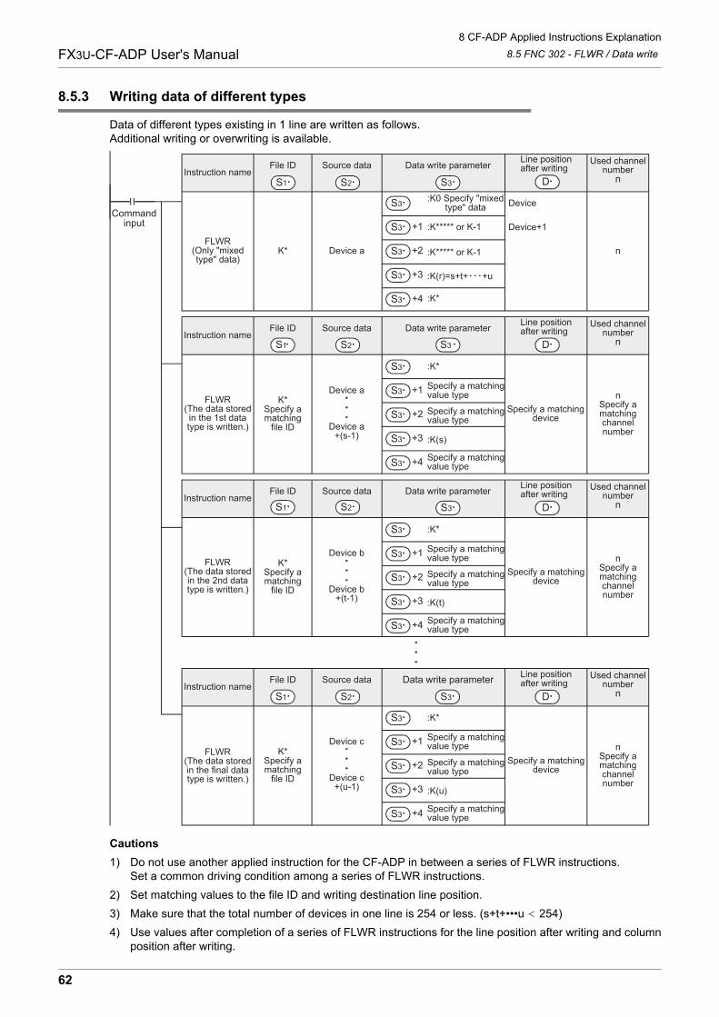
8 CF-ADP Applied Instructions Explanation
8.5 FNC 302 - FLWR / Data writeFX3U-CF-ADP User's Manual
8.5.3 Writing data of different types
Data of different types existing in 1 line are written as follows.Additional writing or overwriting is available.
Cautions
1) Do not use another applied instruction for the CF-ADP in between a series of FLWR instructions.Set a common driving condition among a series of FLWR instructions.
2) Set matching values to the file ID and writing destination line position.
3) Make sure that the total number of devices in one line is 254 or less. (s+t+•••u 254)
4) Use values after completion of a series of FLWR instructions for the line position after writing and columnposition after writing.
FLWR(The data storedin the 2nd datatype is written.)
Instruction name
K*
:K0 Specify "mixed type" data Device
n
Source data Data write parameter
S3S1
File IDLine position after writing
D
Line position after writing
D
Line position after writing
D
Line position after writing
D
Used channelnumber
n
:K***** or K-1
:K***** or K-1
:K(r)=s+t+ +u
Device+1
:K*
Device a
Instruction name
K*Specify amatching
file ID
Specify a matchingdevice
nSpecify amatchingchannelnumber
Source data Data write parameter
S3S1
File ID Used channelnumber
n
Instruction name
K*Specify amatching
file ID
Specify a matchingdevice
nSpecify amatchingchannelnumber
Source data
S2
Data write parameter
S3S1
File ID Used channelnumber
n
Instruction name
K*Specify amatching
file ID
Specify a matchingdevice
nSpecify amatchingchannelnumber
Source data
S2
Data write parameter
S3S1
File ID Used channelnumber
n
FLWR(Only "mixedtype" data)
FLWR(The data storedin the 1st datatype is written.)
FLWR(The data storedin the final datatype is written.)
Device a
Device a+(s-1)
Device b
Device b+(t-1)
Device c
Device c+(u-1)
S3
S3 +1
S3 +2
S3 +3
S3 +4
:K*
Specify a matchingvalue type
Specify a matchingvalue type
:K(s)
Specify a matchingvalue type
S3
S3 +1
S3 +2
S3 +3
S3 +4
:K*
Specify a matchingvalue type
Specify a matchingvalue type
:K(t)
Specify a matchingvalue type
S3
S3 +1
S3 +2
S3 +3
S3 +4
:K*
Specify a matchingvalue type
Specify a matchingvalue type
:K(u)
Specify a matchingvalue type
S3
S3 +1
S3 +2
S3 +3
S3 +4
Commandinput
S2
S2
62
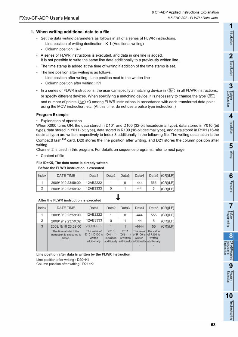
8 CF-ADP Applied Instructions Explanation
8.5 FNC 302 - FLWR / Data writeFX3U-CF-ADP User's Manual
1
Introduction
2
Specification
3
System
C
onfiguration
4
Installation
5
Wiring
6
Functions
7
Before
Program
ming
8
CF-A
DP
Applied
Instructions E
xplanation
9
Program
E
xamples
10
Troubleshooting
1. When writing additional data to a file
• Set the data writing parameters as follows in all of a series of FLWR instructions.
- Line position of writing destination : K-1 (Additional writing)
- Column position : K-1
• A series of FLWR instructions is executed, and data in one line is added.It is not possible to write the same line data additionally to a previously written line.
• The time stamp is added at the time of writing if addition of the time stamp is set.
• The line position after writing is as follows.
- Line position after writing : Line position next to the written line
- Column position after writing : K1
• In a series of FLWR instructions, the user can specify a matching device in in all FLWR instructions,
or specify different devices. When specifying a matching device, it is necessary to change the type
and number of points +3 among FLWR instructions in accordance with each transferred data point using the MOV instruction, etc. (At this time, do not use a pulse type instruction.)
Program Example
• Explanation of operationWhen X000 turns ON, the data stored in D101 and D100 (32-bit hexadecimal type), data stored in Y010 (bittype), data stored in Y011 (bit type), data stored in R100 (16-bit decimal type), and data stored in R101 (16-bitdecimal type) are written respectively to Index 3 additionally in the following file. The writing destination is the
CompactFlashTM card. D20 stores the line position after writing, and D21 stores the column position afterwriting. Channel 2 is used in this program. For details on sequence programs, refer to next page.
• Content of file
S3
S3
S3
DATE TIMEIndex Data1 (CR)(LF)Data5Data4Data3Data2
12AB222212
2009/ 9/ 9 23:59:00 1 0 -444 555 (CR)(LF)
12AB3333 0 1 -44 52009/ 9/ 9 23:59:02 (CR)(LF)
DATE TIMEIndex Data1 (CR)(LF)Data5Data4Data3Data2
12AB2222123
2009/ 9/ 9 23:59:00 1 0 -444 555 (CR)(LF)12AB3333 0 1 -44 523CDFFFF 1 1 -4444 55
2009/ 9/ 9 23:59:022009/ 9/10 23:59:00
(CR)(LF)(CR)(LF)
File ID=K5, The data name is already written.
The time at which theinstruction is executed is
added.
The value ofD101, D100 is
writtenadditionally.
Y010(ON = 1)is written
additionally.
Y011(ON = 1)is written
additionally.
The valueof R100 is
writtenadditionally
.
The valueof R101 is
writtenadditionally
.
Line position after writing : D20=K4 Column position after writing : D21=K1
Line position after data is written by the FLWR instruction
After the FLWR instruction is executed
Before the FLWR instruction is executed
63
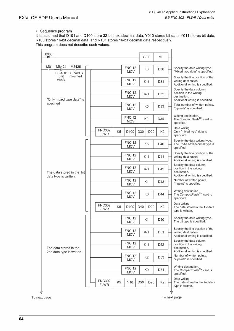
8 CF-ADP Applied Instructions Explanation
8.5 FNC 302 - FLWR / Data writeFX3U-CF-ADP User's Manual
• Sequence programIt is assumed that D101 and D100 store 32-bit hexadecimal data, Y010 stores bit data, Y011 stores bit data,R100 stores 16-bit decimal data, and R101 stores 16-bit decimal data respectively.This program does not describe such values.
Specify the line position of thewriting destination.Additional writing is specified.
D32K-1
D33K5FNC 12 MOV
Specify the data columnposition in the writingdestination.Additional writing is specified.
Data writing.Only "mixed type" data isspecified.
Total number of written points."5 points" is specified.
M8425
CF card ismounted
M0 M8424
CF-ADPunit
ready
Specify the data writing type."Mixed type data" is specified.
FNC 12 MOV
D31K-1
FNC302FLWR
K5
D30K0FNC 12 MOV
D100 D30 D20 K2
FNC 12 MOV
M0SETX000
Specify the line position of thewriting destination.Additional writing is specified.
D52K-1
D53K2FNC 12 MOV
Specify the data columnposition in the writingdestination.Additional writing is specified.Number of written points."2 points" is specified.
FNC 12 MOV
D51K-1
D50K1FNC 12 MOV
FNC 12 MOV
Specify the data writing type.The bit type is specified.
Data writing.The data stored in the 2nd datatype is written.
FNC302FLWR
K5 Y10 D50 D20 K2
To next pageTo next page
The data stored in the2nd data type is written.
"Only mixed type data" isspecified
D34K0FNC 12 MOV
Writing destination.The CompactFlashTM card is
D54K0FNC 12 MOV
Writing destination.The CompactFlashTM card is
Specify the line position of thewriting destination.Additional writing is specified.
D42K-1
D43K1FNC 12 MOV
Specify the data columnposition in the writingdestination.Additional writing is specified.Number of written points."1 point" is specified.
FNC 12 MOV
D41K-1
D40K5FNC 12 MOV
FNC 12 MOV
Specify the data writing type.The 32-bit hexadecimal type isspecified.
Data writing.The data stored in the 1st datatype is written.
FNC302FLWR
K5 D100 D40 D20 K2
The data stored in the 1stdata type is written.
D44K0FNC 12 MOV
Writing destination.The CompactFlashTM card is specified.
specified.
specified.
64
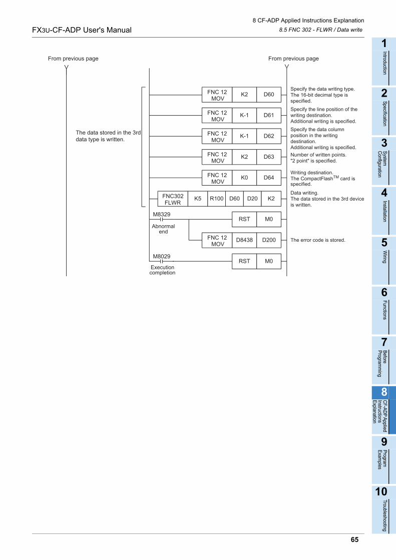
8 CF-ADP Applied Instructions Explanation
8.5 FNC 302 - FLWR / Data writeFX3U-CF-ADP User's Manual
1
Introduction
2
Specification
3
System
C
onfiguration
4
Installation
5
Wiring
6
Functions
7
Before
Program
ming
8
CF-A
DP
Applied
Instructions E
xplanation
9
Program
E
xamples
10
Troubleshooting
D200D8438 The error code is stored.FNC 12 MOV
M0RST
M0RST
M8029
M8329
Specify the line position of thewriting destination.Additional writing is specified.
D62K-1
D63K2FNC 12 MOV
Specify the data columnposition in the writingdestination.Additional writing is specified.
Writing destination.The CompactFlashTM card is
Number of written points."2 point" is specified.
FNC 12 MOV
D61K-1
D60K2FNC 12 MOV
FNC 12 MOV
FNC302FLWR
K5
D64K0FNC 12 MOV
R100 D60 D20 K2
Specify the data writing type.The 16-bit decimal type isspecified.
Data writing.The data stored in the 3rd deviceis written.
From previous pageFrom previous page
The data stored in the 3rddata type is written.
Executioncompletion
Abnormalend
specified.
65
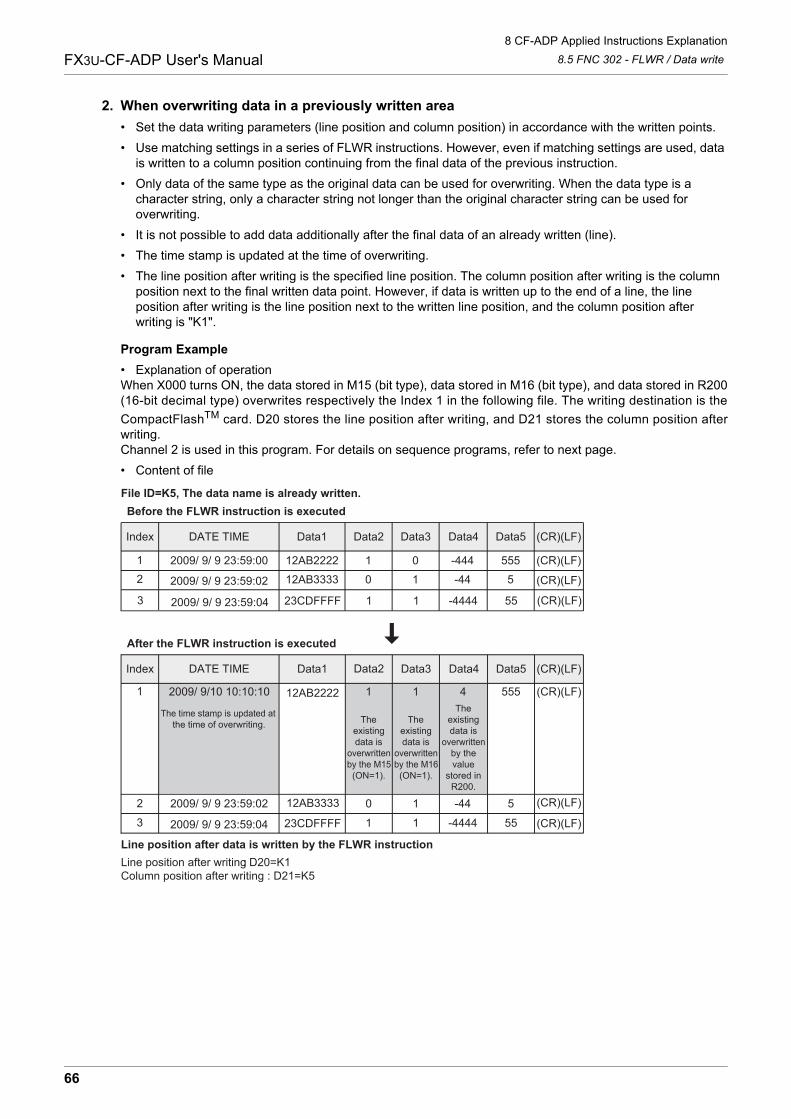
8 CF-ADP Applied Instructions Explanation
8.5 FNC 302 - FLWR / Data writeFX3U-CF-ADP User's Manual
2. When overwriting data in a previously written area
• Set the data writing parameters (line position and column position) in accordance with the written points.
• Use matching settings in a series of FLWR instructions. However, even if matching settings are used, data is written to a column position continuing from the final data of the previous instruction.
• Only data of the same type as the original data can be used for overwriting. When the data type is a character string, only a character string not longer than the original character string can be used for overwriting.
• It is not possible to add data additionally after the final data of an already written (line).
• The time stamp is updated at the time of overwriting.
• The line position after writing is the specified line position. The column position after writing is the column position next to the final written data point. However, if data is written up to the end of a line, the line position after writing is the line position next to the written line position, and the column position after writing is "K1".
Program Example
• Explanation of operationWhen X000 turns ON, the data stored in M15 (bit type), data stored in M16 (bit type), and data stored in R200(16-bit decimal type) overwrites respectively the Index 1 in the following file. The writing destination is the
CompactFlashTM card. D20 stores the line position after writing, and D21 stores the column position afterwriting. Channel 2 is used in this program. For details on sequence programs, refer to next page.
• Content of file
DATE TIMEIndex Data1 (CR)(LF)Data5Data4Data3Data2
12AB222212
2009/ 9/ 9 23:59:00 1 0 -444 555 (CR)(LF)
12AB3333 0 1 -44 52009/ 9/ 9 23:59:02 (CR)(LF)
DATE TIMEIndex Data1 (CR)(LF)Data5Data4Data3Data2
12AB33332
3
1
2009/ 9/ 9 23:59:02 0 1 -44 5 (CR)(LF)
23CDFFFF 1 1 -4444 55
12AB2222 1 1 4 555
2009/ 9/ 9 23:59:04
2009/ 9/10 10:10:10
(CR)(LF)
(CR)(LF)
File ID=K5, The data name is already written.
The time stamp is updated atthe time of overwriting. The
existingdata is
overwrittenby the M15
(ON=1).
Theexistingdata is
overwrittenby the M16
(ON=1).
Theexistingdata is
overwrittenby thevalue
stored inR200.
Line position after writing : D20=K1Column position after writing : D21=K5
Line position after data is written by the FLWR instruction
3 23CDFFFF 1 1 -4444 552009/ 9/ 9 23:59:04 (CR)(LF)
After the FLWR instruction is executed
Before the FLWR instruction is executed
66
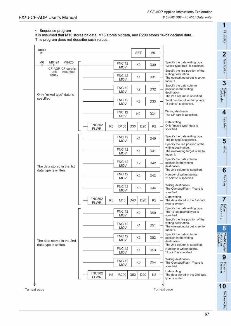
8 CF-ADP Applied Instructions Explanation
8.5 FNC 302 - FLWR / Data writeFX3U-CF-ADP User's Manual
1
Introduction
2
Specification
3
System
C
onfiguration
4
Installation
5
Wiring
6
Functions
7
Before
Program
ming
8
CF-A
DP
Applied
Instructions E
xplanation
9
Program
E
xamples
10
Troubleshooting
• Sequence programIt is assumed that M15 stores bit data, M16 stores bit data, and R200 stores 16-bit decimal data.This program does not describe such values.
Specify the line position of thewriting destination.The overwriting target is set toIndex 1.
D32K2
D33K3FNC 12 MOV
Specify the data columnposition in the writingdestination.The 2nd column is specified.
Data writing.Only "mixed type" data isspecified.
Total number of written points."3 points" is specified.
M8425
CF card ismounted
M0 M8424
CF-ADPunit
ready
Specify the data writing type."Mixed type data" is specified.
FNC 12 MOV
D31K1
FNC302FLWR
K5
D30K0FNC 12 MOV
D100 D30 D20 K2
FNC 12 MOV
M0SETX000
Specify the line position of thewriting destination.The overwriting target is set toIndex 1.
D52K2
D53K1FNC 12 MOV
Specify the data columnposition in the writingdestination.The 2nd column is specified.Number of written points."1 point" is specified.
FNC 12 MOV
D51K1
D50K2FNC 12 MOV
FNC 12 MOV
Specify the data writing type.The 16-bit decimal type isspecified.
Data writing.The data stored in the 2nd datatype is written.
FNC302FLWR
K5 R200 D50 D20 K2
To next pageTo next page
The data stored in the 2nddata type is written.
Only "mixed type" data isspecified
D34K0FNC 12 MOV
Writing destination.The CF card is specified.
D54K0FNC 12 MOV
Writing destination.The CompactFlashTM card is
Specify the line position of thewriting destination.The overwriting target is set toIndex 1.
D42K2
D43K2FNC 12 MOV
Specify the data columnposition in the writingdestination.The 2nd column is specified.Number of written points."2 points" is specified.
FNC 12 MOV
D41K1
D40K1FNC 12 MOV
FNC 12 MOV
Specify the data writing type.The bit type is specified.
Data writing.The data stored in the 1st datatype is written.
FNC302FLWR
K5 M15 D40 D20 K2
The data stored in the 1stdata type is written.
D44K0FNC 12 MOV
Writing destination.The CompactFlashTM card is
specified.
specified.
67
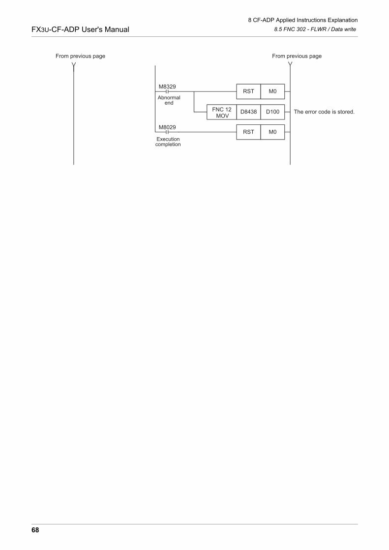
8 CF-ADP Applied Instructions Explanation
8.5 FNC 302 - FLWR / Data writeFX3U-CF-ADP User's Manual
D100D8438 The error code is stored.FNC 12 MOV
M0RST
M0RST
M8029
M8329
From previous pageFrom previous page
Executioncompletion
Abnormalend
68
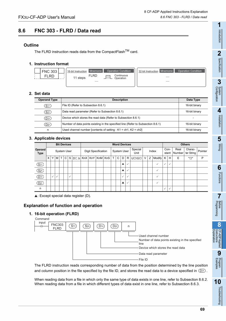
8 CF-ADP Applied Instructions Explanation
8.6 FNC 303 - FLRD / Data readFX3U-CF-ADP User's Manual
1
Introduction
2
Specification
3
System
C
onfiguration
4
Installation
5
Wiring
6
Functions
7
Before
Program
ming
8
CF-A
DP
Applied
Instructions E
xplanation
9
Program
E
xamples
10
Troubleshooting
8.6 FNC 303 - FLRD / Data read
Outline
The FLRD instruction reads data from the CompactFlashTM card.
1. Instruction format
2. Set data
3. Applicable devices
: Except special data register (D).
Explanation of function and operation
1. 16-bit operation (FLRD)
The FLRD instruction reads corresponding number of data from the position determined by the line position
and column position in the file specified by the file ID, and stores the read data to a device specified in .
When reading data from a file in which only the same type of data exists in one line, refer to Subsection 8.6.2.When reading data from a file in which different types of data exist in one line, refer to Subsection 8.6.3.
Operand Type Description Data Type
File ID (Refer to Subsection 8.6.1) 16-bit binary
Data read parameter (Refer to Subsection 8.6.1) 16-bit binary
Device which stores the read data (Refer to Subsection 8.6.1) -
Number of data points existing in the specified line (Refer to Subsection 8.6.1) 16-bit binary
n Used channel number [contents of setting : K1 = ch1, K2 = ch2] 16-bit binary
Operand Type
Bit Devices Word Devices Others
System User Digit Specification System UserSpecial
UnitIndex
Con-stant
Real Number
Charac-ter String
Pointer
X Y M T C S D .b KnX KnY KnM KnS T C D R U \G V Z Modify K H E " " P
n
FNC 303FLRD
Mnemonic Operation Condition16-bit Instruction
11 steps FLRDMnemonic Operation Condition
ContinuousOperation
32-bit Instruction
S1
S2
D1
D2
S1
S2
D1
D2
D2 D1S1 S2
Commandinput
FNC303FLRD
n
Data read parameter
Used channel numberNumber of data points existing in the specifiedlineDevice which stores the read data
File ID
D1
69
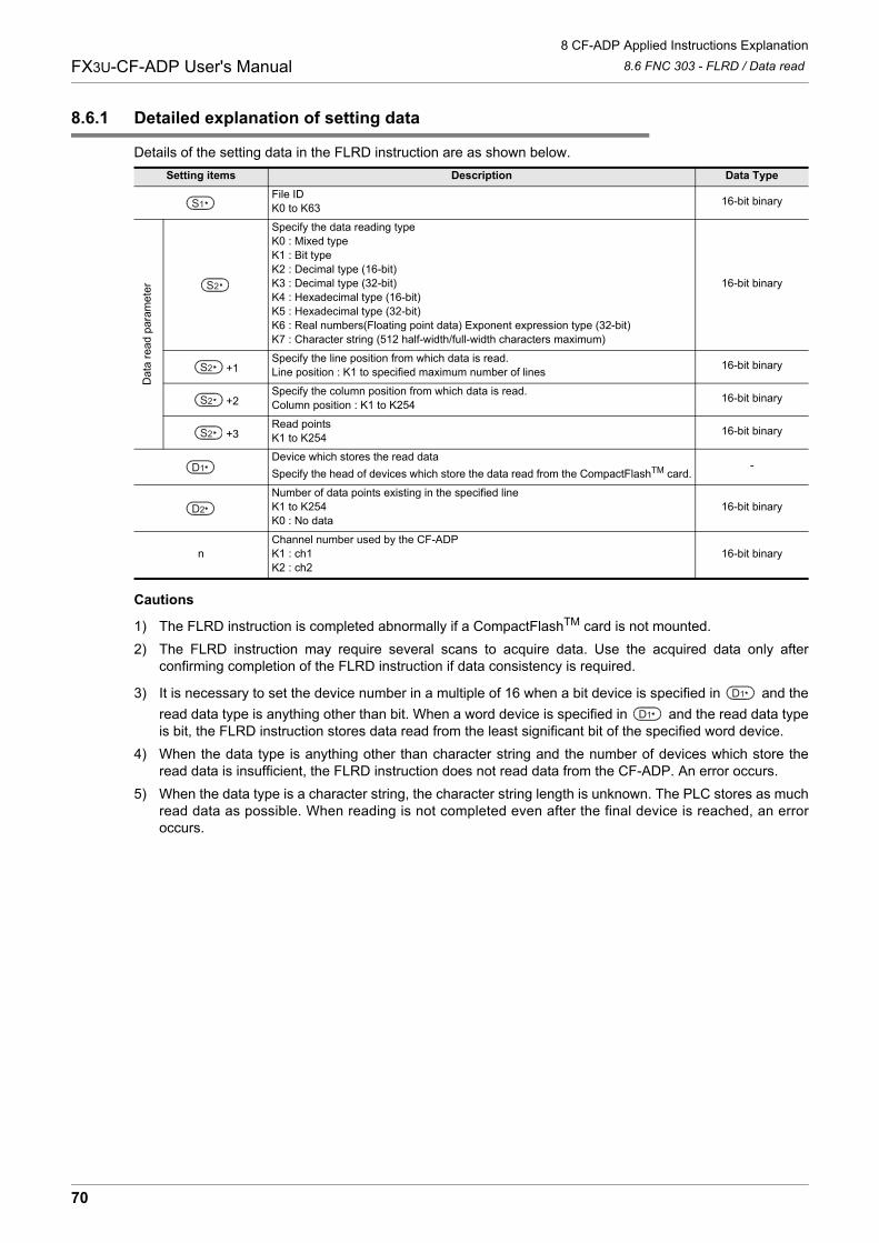
8 CF-ADP Applied Instructions Explanation
8.6 FNC 303 - FLRD / Data readFX3U-CF-ADP User's Manual
8.6.1 Detailed explanation of setting data
Details of the setting data in the FLRD instruction are as shown below.
Cautions
1) The FLRD instruction is completed abnormally if a CompactFlashTM card is not mounted.
2) The FLRD instruction may require several scans to acquire data. Use the acquired data only afterconfirming completion of the FLRD instruction if data consistency is required.
3) It is necessary to set the device number in a multiple of 16 when a bit device is specified in and the
read data type is anything other than bit. When a word device is specified in and the read data typeis bit, the FLRD instruction stores data read from the least significant bit of the specified word device.
4) When the data type is anything other than character string and the number of devices which store theread data is insufficient, the FLRD instruction does not read data from the CF-ADP. An error occurs.
5) When the data type is a character string, the character string length is unknown. The PLC stores as muchread data as possible. When reading is not completed even after the final device is reached, an erroroccurs.
Setting items Description Data Type
File IDK0 to K63
16-bit binary
Dat
a re
ad p
aram
ete
r
Specify the data reading typeK0 : Mixed typeK1 : Bit typeK2 : Decimal type (16-bit)K3 : Decimal type (32-bit)K4 : Hexadecimal type (16-bit)K5 : Hexadecimal type (32-bit)K6 : Real numbers(Floating point data) Exponent expression type (32-bit)K7 : Character string (512 half-width/full-width characters maximum)
16-bit binary
+1Specify the line position from which data is read.Line position : K1 to specified maximum number of lines
16-bit binary
+2Specify the column position from which data is read.Column position : K1 to K254
16-bit binary
+3Read pointsK1 to K254
16-bit binary
Device which stores the read data
Specify the head of devices which store the data read from the CompactFlashTM card.-
Number of data points existing in the specified lineK1 to K254K0 : No data
16-bit binary
nChannel number used by the CF-ADPK1 : ch1K2 : ch2
16-bit binary
S1
S2
S2
S2
S2
D1
D2
D1
D1
70
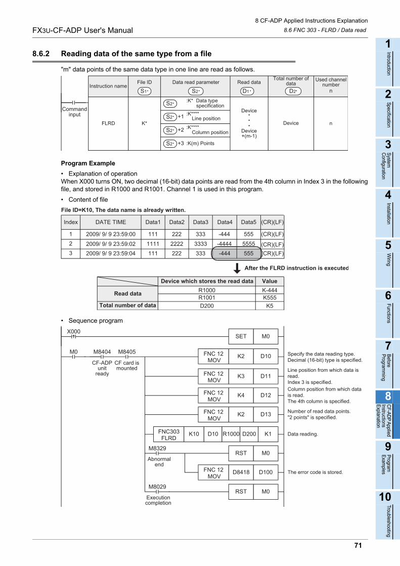
8 CF-ADP Applied Instructions Explanation
8.6 FNC 303 - FLRD / Data readFX3U-CF-ADP User's Manual
1
Introduction
2
Specification
3
System
C
onfiguration
4
Installation
5
Wiring
6
Functions
7
Before
Program
ming
8
CF-A
DP
Applied
Instructions E
xplanation
9
Program
E
xamples
10
Troubleshooting
8.6.2 Reading data of the same type from a file
"m" data points of the same data type in one line are read as follows.
Program Example
• Explanation of operationWhen X000 turns ON, two decimal (16-bit) data points are read from the 4th column in Index 3 in the followingfile, and stored in R1000 and R1001. Channel 1 is used in this program.
• Content of file
• Sequence program
Instruction name
FLRD
:K* Data type specificationS2
S2 +1
S2 +2
S2 +3
:K**** Line position
:K**** Column position
:K(m) Points
K*
Device
Device+(m-1)
Device n
S2
Data read parameter
D1
Read data
S1
File ID
D2
Total number ofdata
Used channelnumber
n
Commandinput
DATE TIMEIndex Data1 (CR)(LF)Data5Data4Data3Data2
111123
2009/ 9/ 9 23:59:00 222 333 -444 555 (CR)(LF)
1111 2222 3333 -4444 5555111 222 333 -444 555
2009/ 9/ 9 23:59:022009/ 9/ 9 23:59:04
(CR)(LF)(CR)(LF)
Device which stores the read data Value
Read data
Total number of data
R1000 K-444R1001 K555D200 K5
File ID=K10, The data name is already written.
After the FLRD instruction is executed
Line position from which data isread.Index 3 is specified.
D12K4
D13K2FNC 12 MOV
Column position from which datais read.The 4th column is specified.
Data reading.
Number of read data points."2 points" is specified.
M8405
CF card ismounted
M0 M8404
CF-ADPunit
ready
Specify the data reading type.Decimal (16-bit) type is specified.
FNC 12 MOV
D11K3
FNC303FLRD
K10
D100D8418 The error code is stored.FNC 12 MOV
M0RST
M0RST
M8029
M8329
D10K2FNC 12 MOV
D10 R1000 D200 K1
FNC 12 MOV
M0SETX000
Executioncompletion
Abnormalend
71
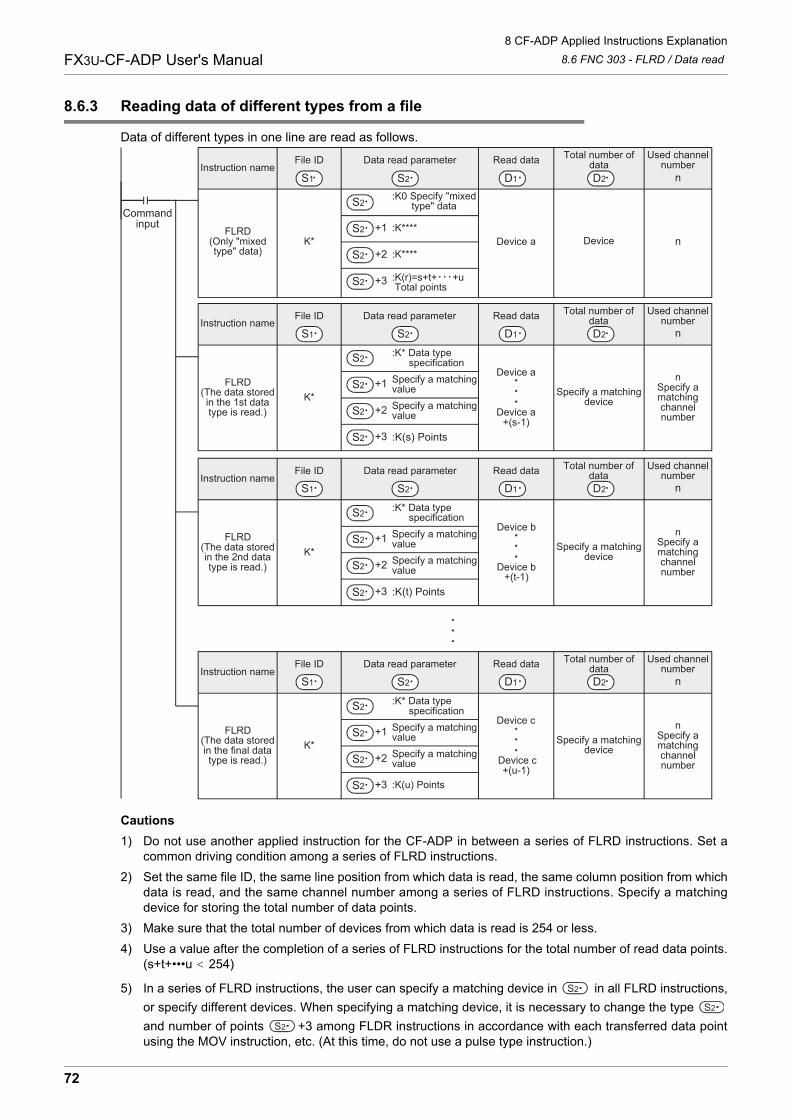
8 CF-ADP Applied Instructions Explanation
8.6 FNC 303 - FLRD / Data readFX3U-CF-ADP User's Manual
8.6.3 Reading data of different types from a file
Data of different types in one line are read as follows.
Cautions
1) Do not use another applied instruction for the CF-ADP in between a series of FLRD instructions. Set acommon driving condition among a series of FLRD instructions.
2) Set the same file ID, the same line position from which data is read, the same column position from whichdata is read, and the same channel number among a series of FLRD instructions. Specify a matchingdevice for storing the total number of data points.
3) Make sure that the total number of devices from which data is read is 254 or less.
4) Use a value after the completion of a series of FLRD instructions for the total number of read data points.(s+t+•••u 254)
5) In a series of FLRD instructions, the user can specify a matching device in in all FLRD instructions,
or specify different devices. When specifying a matching device, it is necessary to change the type
and number of points +3 among FLDR instructions in accordance with each transferred data pointusing the MOV instruction, etc. (At this time, do not use a pulse type instruction.)
Commandinput
S1 D1 D2Instruction name
Data read parameterFile ID Read data Total number ofdata
Used channelnumber
FLRD(Only "mixedtype" data)
n
:K0 Specify "mixed type" data
+1
+2
+3
:K****
:K****
:K(r)=s+t+ +u Total points
K* Device nDevice a
S1 D1 D2Instruction name
Data read parameterFile ID Read data Total number ofdata
Used channelnumber
FLRD(The data storedin the 1st datatype is read.)
n
:K* Data type specification
+1
+2
+3
Specify a matchingvalueSpecify a matchingvalue
:K(s) Points
K* Specify a matchingdevice
nSpecify amatchingchannelnumber
Device a
Device a+(s-1)
S1 D1 D2Instruction name
Data read parameterFile ID Read data Total number ofdata
Used channelnumber
FLRD(The data storedin the 2nd datatype is read.)
n
:K* Data type specification
+1
+2
+3
Specify a matchingvalueSpecify a matchingvalue
:K(t) Points
K* Specify a matchingdevice
nSpecify amatchingchannelnumber
Device b
Device b+(t-1)
S1 D1 D2Instruction name
Data read parameterFile ID Read data Total number ofdata
Used channelnumber
FLRD(The data storedin the final datatype is read.)
n
:K* Data type specification
+1
+2
+3
Specify a matchingvalueSpecify a matchingvalue
:K(u) Points
K* Specify a matchingdevice
nSpecify amatchingchannelnumber
Device c
Device c+(u-1)
S2
S2
S2
S2
S2
S2
S2
S2
S2
S2
S2
S2
S2
S2
S2
S2
S2
S2
S2
S2
S2
S2
S2
72
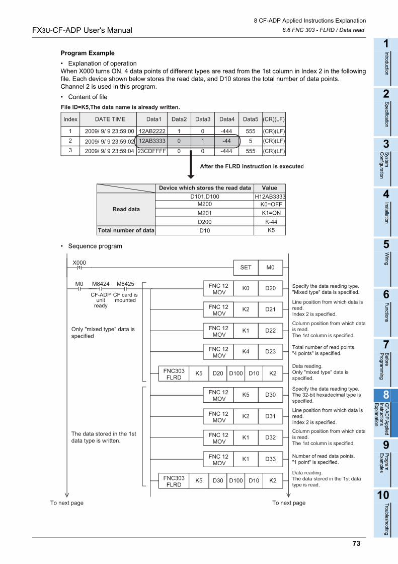
8 CF-ADP Applied Instructions Explanation
8.6 FNC 303 - FLRD / Data readFX3U-CF-ADP User's Manual
1
Introduction
2
Specification
3
System
C
onfiguration
4
Installation
5
Wiring
6
Functions
7
Before
Program
ming
8
CF-A
DP
Applied
Instructions E
xplanation
9
Program
E
xamples
10
Troubleshooting
Program Example
• Explanation of operationWhen X000 turns ON, 4 data points of different types are read from the 1st column in Index 2 in the followingfile. Each device shown below stores the read data, and D10 stores the total number of data points. Channel 2 is used in this program.
• Content of file
• Sequence program
DATE TIMEIndex Data1 (CR)(LF)Data5Data4Data3Data2
12AB2222123
2009/ 9/ 9 23:59:00 1 0 -444 555 (CR)(LF)
12AB3333 0 1 -44 5
23CDFFFF 0 0 -444 5552009/ 9/ 9 23:59:022009/ 9/ 9 23:59:04
(CR)(LF)
(CR)(LF)
File ID=K5,The data name is already written.
After the FLRD instruction is executed
Device which stores the read data Value
Read data
Total number of data
D101,D100 H12AB3333M200 K0=OFF
D10 K5
M201 K1=OND200 K-44
Line position from which data isread.Index 2 is specified.
D22K1
D23K4FNC 12 MOV
Column position from which datais read.The 1st column is specified.
Data reading.Only "mixed type" data isspecified.
Total number of read points."4 points" is specified.
M8425
CF card ismounted
M0 M8424
CF-ADPunit
ready
Specify the data reading type."Mixed type" data is specified.
FNC 12 MOV
D21K2
FNC303FLRD
K5
D20K0FNC 12 MOV
D20 D100 D10 K2
FNC 12 MOV
M0SETX000
Line position from which data isread.Index 2 is specified.
D32K1
D33K1FNC 12 MOV
Column position from which datais read.The 1st column is specified.
Number of read data points."1 point" is specified.
FNC 12 MOV
D31K2
D30K5FNC 12 MOV
FNC 12 MOV
Specify the data reading type.The 32-bit hexadecimal type isspecified.
Data reading.The data stored in the 1st datatype is read.
FNC303FLRD
K5 D30 D100 D10 K2
To next pageTo next page
The data stored in the 1stdata type is written.
Only "mixed type" data isspecified
73
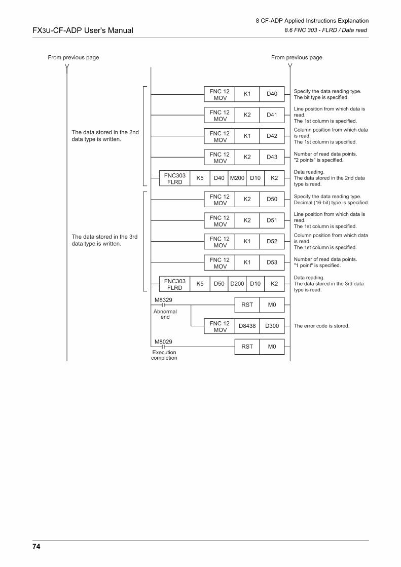
8 CF-ADP Applied Instructions Explanation
8.6 FNC 303 - FLRD / Data readFX3U-CF-ADP User's Manual
D300D8438 The error code is stored.FNC 12 MOV
M0RST
M0RST
M8029
M8329
Line position from which data isread.The 1st column is specified.
D42K1
D43K2FNC 12 MOV
Column position from which datais read.The 1st column is specified.
Data reading.The data stored in the 2nd datatype is read.
Number of read data points."2 points" is specified.
FNC 12 MOV
D41K2
FNC303FLRD
K5
D40K1FNC 12 MOV
D40 M200 D10 K2
FNC 12 MOV
Line position from which data isread.The 1st column is specified.
D52K1
D53K1FNC 12 MOV
Column position from which datais read.The 1st column is specified.
Data reading.The data stored in the 3rd datatype is read.
Number of read data points."1 point" is specified.
FNC 12 MOV
D51K2
FNC303FLRD
K5
D50K2FNC 12 MOV
D50 D200 D10 K2
FNC 12 MOV
Specify the data reading type.The bit type is specified.
Specify the data reading type.Decimal (16-bit) type is specified.
From previous pageFrom previous page
The data stored in the 2nddata type is written.
The data stored in the 3rddata type is written.
Executioncompletion
Abnormalend
74
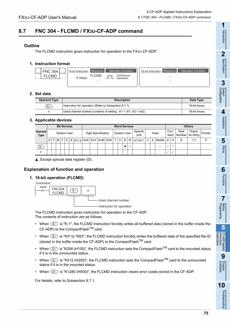
8 CF-ADP Applied Instructions Explanation
8.7 FNC 304 - FLCMD / FX3U-CF-ADP commandFX3U-CF-ADP User's Manual
1
Introduction
2
Specification
3
System
C
onfiguration
4
Installation
5
Wiring
6
Functions
7
Before
Program
ming
8
CF-A
DP
Applied
Instructions E
xplanation
9
Program
E
xamples
10
Troubleshooting
8.7 FNC 304 - FLCMD / FX3U-CF-ADP command
OutlineThe FLCMD instruction gives instruction for operation to the FX3U-CF-ADP.
1. Instruction format
2. Set data
3. Applicable devices
: Except special data register (D).
Explanation of function and operation
1. 16-bit operation (FLCMD)
The FLCMD instruction gives instruction for operation to the CF-ADP. The contents of instruction are as follows.
• When is "K-1", the FLCMD instruction forcibly writes all buffered data (stored in the buffer inside the
CF-ADP) to the CompactFlashTM card.
• When is "K0" to "K63", the FLCMD instruction forcibly writes the buffered data of the specified file ID
(stored in the buffer inside the CF-ADP) to the CompactFlashTM card.
• When is "K256 (H100)", the FLCMD instruction sets the CompactFlashTM card to the mounted status if it is in the unmounted status.
• When is "K512 (H200)", the FLCMD instruction sets the CompactFlashTM card to the unmounted status if it is in the mounted status.
• When is "K1280 (H500)", the FLCMD instruction clears error codes stored in the CF-ADP.
For details, refer to Subsection 8.7.1.
Operand Type Description Data Type
Instruction for operation (Refer to Subsection 8.7.1) 16-bit binary
n Used channel number [contents of setting : K1 = ch1, K2 = ch2] 16-bit binary
Operand Type
Bit Devices Word Devices Others
System User Digit Specification System UserSpecial
UnitIndex
Con-stant
Real Number
Charac-ter String
Pointer
X Y M T C S D .b KnX KnY KnM KnS T C D R U \G V Z Modify K H E " " P
n
FNC 304FLCMD
Mnemonic Operation Condition16-bit Instruction
5 steps FLCMDMnemonic Operation Condition
ContinuousOperation
32-bit Instruction
S
S
S
Commandinput
FNC304FLCMD
n
Used channel number
Instruction for operation
S
S
S
S
S
75
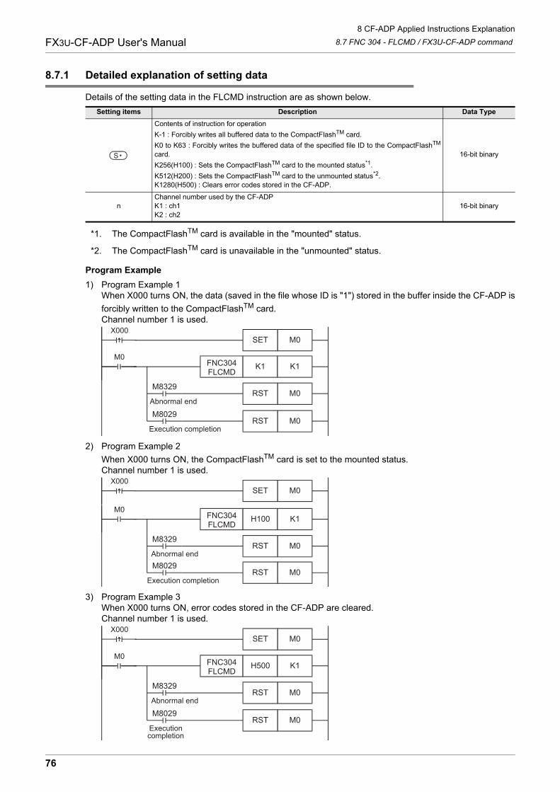
8 CF-ADP Applied Instructions Explanation
8.7 FNC 304 - FLCMD / FX3U-CF-ADP commandFX3U-CF-ADP User's Manual
8.7.1 Detailed explanation of setting data
Details of the setting data in the FLCMD instruction are as shown below.
*1. The CompactFlashTM card is available in the "mounted" status.
*2. The CompactFlashTM card is unavailable in the "unmounted" status.
Program Example
1) Program Example 1When X000 turns ON, the data (saved in the file whose ID is "1") stored in the buffer inside the CF-ADP is
forcibly written to the CompactFlashTM card.Channel number 1 is used.
2) Program Example 2
When X000 turns ON, the CompactFlashTM card is set to the mounted status.Channel number 1 is used.
3) Program Example 3When X000 turns ON, error codes stored in the CF-ADP are cleared.Channel number 1 is used.
Setting items Description Data Type
Contents of instruction for operation
K-1 : Forcibly writes all buffered data to the CompactFlashTM card.
K0 to K63 : Forcibly writes the buffered data of the specified file ID to the CompactFlashTM
card.
K256(H100) : Sets the CompactFlashTM card to the mounted status*1.
K512(H200) : Sets the CompactFlashTM card to the unmounted status*2.K1280(H500) : Clears error codes stored in the CF-ADP.
16-bit binary
nChannel number used by the CF-ADPK1 : ch1K2 : ch2
16-bit binary
S
X000M0SET
M0FNC304FLCMD
K1 K1
M8329
Abnormal endM0RST
M8029
Execution completionM0RST
X000M0SET
M0FNC304FLCMD
H100 K1
M8329
Abnormal endM0RST
M8029
Execution completionM0RST
X000M0SET
M0FNC304FLCMD
H500 K1
M8329
Abnormal endM0RST
M8029
Executioncompletion
M0RST
76
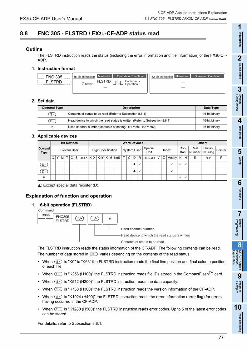
8 CF-ADP Applied Instructions Explanation
8.8 FNC 305 - FLSTRD / FX3U-CF-ADP status readFX3U-CF-ADP User's Manual
1
Introduction
2
Specification
3
System
C
onfiguration
4
Installation
5
Wiring
6
Functions
7
Before
Program
ming
8
CF-A
DP
Applied
Instructions E
xplanation
9
Program
E
xamples
10
Troubleshooting
8.8 FNC 305 - FLSTRD / FX3U-CF-ADP status read
OutlineThe FLSTRD instruction reads the status (including the error information and file information) of the FX3U-CF-ADP.
1. Instruction format
2. Set data
3. Applicable devices
: Except special data register (D).
Explanation of function and operation
1. 16-bit operation (FLSTRD)
The FLSTRD instruction reads the status information of the CF-ADP. The following contents can be read.
The number of data stored in varies depending on the contents of the read status.
• When is "K0" to "K63" the FLSTRD instruction reads the final line position and final column position of each file.
• When is "K256 (H100)" the FLSTRD instruction reads file IDs stored in the CompactFlashTM card.
• When is "K512 (H200)" the FLSTRD instruction reads the data capacity.
• When is "K768 (H300)" the FLSTRD instruction reads the version information of the CF-ADP.
• When is "K1024 (H400)" the FLSTRD instruction reads the error information (error flag) for errors having occurred in the CF-ADP.
• When is "K1280 (H500)" the FLSTRD instruction reads error codes. Up to 5 of the latest error codes can be stored.
For details, refer to Subsection 8.8.1.
Operand Type Description Data Type
Contents of status to be read (Refer to Subsection 8.8.1) 16-bit binary
Head device to which the read status is written (Refer to Subsection 8.8.1) 16-bit binary
n Used channel number [contents of setting : K1 = ch1, K2 = ch2] 16-bit binary
Operand Type
Bit Devices Word Devices Others
System User Digit Specification System UserSpecial
UnitIndex
Con-stant
Real Number
Charac-ter String
Pointer
X Y M T C S D .b KnX KnY KnM KnS T C D R U \G V Z Modify K H E " " P
n
FNC 305FLSTRD
Mnemonic Operation Condition16-bit Instruction
7 steps FLSTRDMnemonic Operation Condition
ContinuousOperation
32-bit Instruction
S
D
S
D
S D
Commandinput
FNC305FLSTRD
n
Used channel number
Head device to which the read status is written
Contents of status to be read
D
S
S
S
S
S
S
77
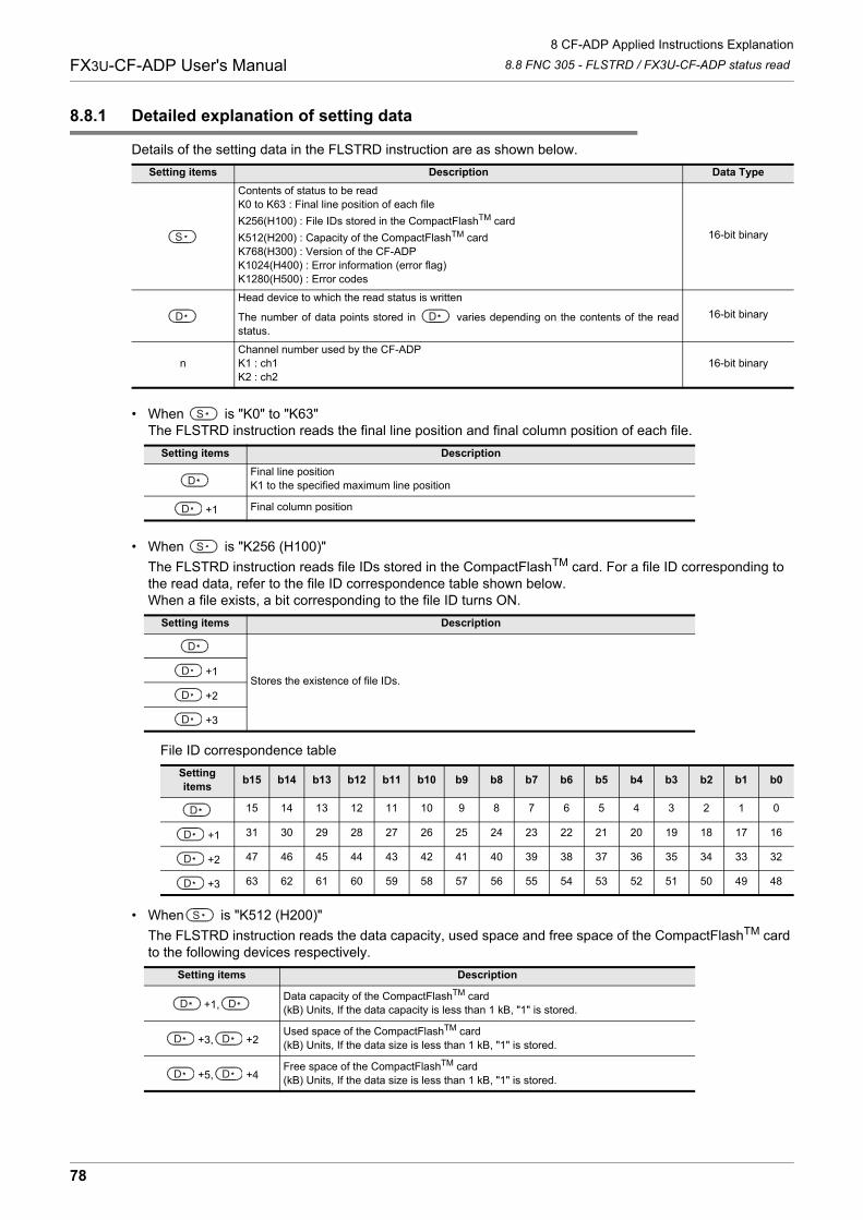
8 CF-ADP Applied Instructions Explanation
8.8 FNC 305 - FLSTRD / FX3U-CF-ADP status readFX3U-CF-ADP User's Manual
8.8.1 Detailed explanation of setting data
Details of the setting data in the FLSTRD instruction are as shown below.
• When is "K0" to "K63"The FLSTRD instruction reads the final line position and final column position of each file.
• When is "K256 (H100)"
The FLSTRD instruction reads file IDs stored in the CompactFlashTM card. For a file ID corresponding to the read data, refer to the file ID correspondence table shown below. When a file exists, a bit corresponding to the file ID turns ON.
File ID correspondence table
• When is "K512 (H200)"
The FLSTRD instruction reads the data capacity, used space and free space of the CompactFlashTM card to the following devices respectively.
Setting items Description Data Type
Contents of status to be readK0 to K63 : Final line position of each file
K256(H100) : File IDs stored in the CompactFlashTM card
K512(H200) : Capacity of the CompactFlashTM cardK768(H300) : Version of the CF-ADPK1024(H400) : Error information (error flag)K1280(H500) : Error codes
16-bit binary
Head device to which the read status is written
The number of data points stored in varies depending on the contents of the readstatus.
16-bit binary
nChannel number used by the CF-ADPK1 : ch1K2 : ch2
16-bit binary
Setting items Description
Final line positionK1 to the specified maximum line position
+1 Final column position
Setting items Description
Stores the existence of file IDs.+1
+2
+3
Setting items
b15 b14 b13 b12 b11 b10 b9 b8 b7 b6 b5 b4 b3 b2 b1 b0
15 14 13 12 11 10 9 8 7 6 5 4 3 2 1 0
+1 31 30 29 28 27 26 25 24 23 22 21 20 19 18 17 16
+2 47 46 45 44 43 42 41 40 39 38 37 36 35 34 33 32
+3 63 62 61 60 59 58 57 56 55 54 53 52 51 50 49 48
Setting items Description
+1,Data capacity of the CompactFlashTM card(kB) Units, If the data capacity is less than 1 kB, "1" is stored.
+3, +2Used space of the CompactFlashTM card(kB) Units, If the data size is less than 1 kB, "1" is stored.
+5, +4Free space of the CompactFlashTM card(kB) Units, If the data size is less than 1 kB, "1" is stored.
S
D D
S
D
D
S
D
D
D
D
D
D
D
D
S
D D
D D
D D
78
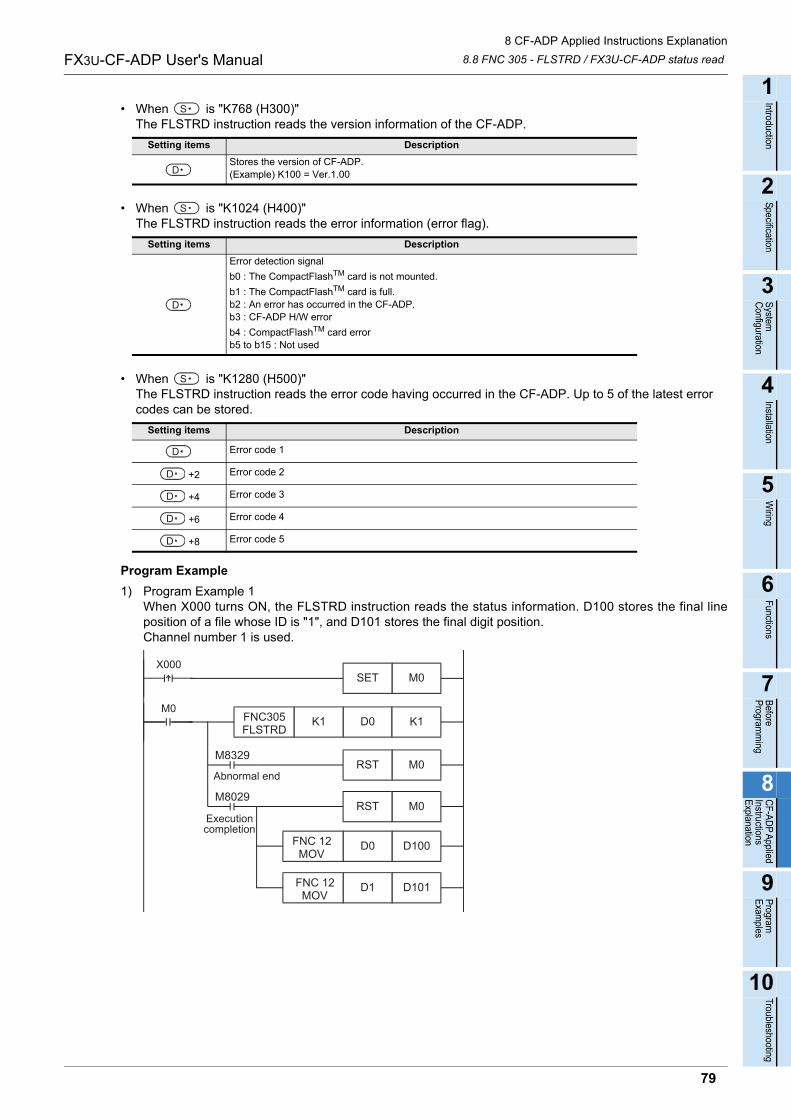
8 CF-ADP Applied Instructions Explanation
8.8 FNC 305 - FLSTRD / FX3U-CF-ADP status readFX3U-CF-ADP User's Manual
1
Introduction
2
Specification
3
System
C
onfiguration
4
Installation
5
Wiring
6
Functions
7
Before
Program
ming
8
CF-A
DP
Applied
Instructions E
xplanation
9
Program
E
xamples
10
Troubleshooting
• When is "K768 (H300)"The FLSTRD instruction reads the version information of the CF-ADP.
• When is "K1024 (H400)"The FLSTRD instruction reads the error information (error flag).
• When is "K1280 (H500)"The FLSTRD instruction reads the error code having occurred in the CF-ADP. Up to 5 of the latest error codes can be stored.
Program Example
1) Program Example 1When X000 turns ON, the FLSTRD instruction reads the status information. D100 stores the final lineposition of a file whose ID is "1", and D101 stores the final digit position.Channel number 1 is used.
Setting items Description
Stores the version of CF-ADP.(Example) K100 = Ver.1.00
Setting items Description
Error detection signal
b0 : The CompactFlashTM card is not mounted.
b1 : The CompactFlashTM card is full.b2 : An error has occurred in the CF-ADP.b3 : CF-ADP H/W error
b4 : CompactFlashTM card errorb5 to b15 : Not used
Setting items Description
Error code 1
+2 Error code 2
+4 Error code 3
+6 Error code 4
+8 Error code 5
S
D
S
D
S
D
D
D
D
D
X000M0SET
M0FNC305FLSTRD
D0 K1K1
M8029
D100D0
D101D1 FNC 12 MOV
FNC 12 MOV
Executioncompletion
M8329
Abnormal endM0RST
M0RST
79
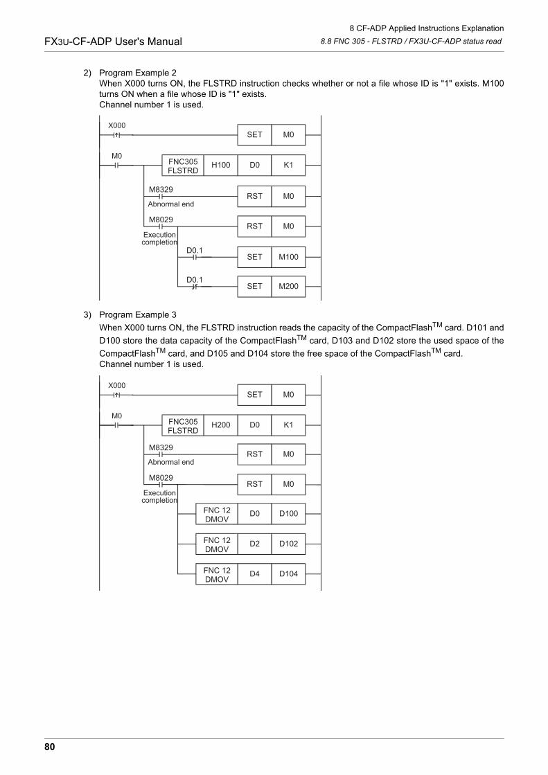
8 CF-ADP Applied Instructions Explanation
8.8 FNC 305 - FLSTRD / FX3U-CF-ADP status readFX3U-CF-ADP User's Manual
2) Program Example 2When X000 turns ON, the FLSTRD instruction checks whether or not a file whose ID is "1" exists. M100turns ON when a file whose ID is "1" exists.Channel number 1 is used.
3) Program Example 3
When X000 turns ON, the FLSTRD instruction reads the capacity of the CompactFlashTM card. D101 and
D100 store the data capacity of the CompactFlashTM card, D103 and D102 store the used space of the
CompactFlashTM card, and D105 and D104 store the free space of the CompactFlashTM card.Channel number 1 is used.
X000M0SET
M0FNC305FLSTRD
D0 K1H100
M100SET
M200SET
M8029
D0.1
D0.1
Executioncompletion
M8329
Abnormal endM0RST
M0RST
X000M0SET
M0FNC305FLSTRD
D0 K1H200
M8029
D100D0
D102D2FNC 12DMOV
FNC 12DMOV
D104D4FNC 12DMOV
Executioncompletion
M8329
Abnormal endM0RST
M0RST
80
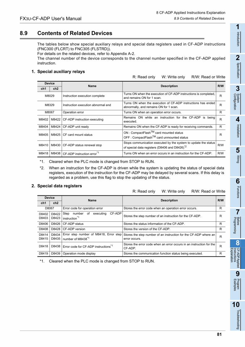
8 CF-ADP Applied Instructions Explanation
8.9 Contents of Related DevicesFX3U-CF-ADP User's Manual
1
Introduction
2
Specification
3
System
C
onfiguration
4
Installation
5
Wiring
6
Functions
7
Before
Program
ming
8
CF-A
DP
Applied
Instructions E
xplanation
9
Program
E
xamples
10
Troubleshooting
8.9 Contents of Related Devices
The tables below show special auxiliary relays and special data registers used in CF-ADP instructions(FNC300 (FLCRT) to FNC305 (FLSTRD)).For details on the related devices, refer to Appendix A-2.The channel number of the device corresponds to the channel number specified in the CF-ADP appliedinstruction.
1. Special auxiliary relaysR: Read only W: Write only R/W: Read or Write
*1. Cleared when the PLC mode is changed from STOP to RUN.
*2. When an instruction for the CF-ADP is driven while the system is updating the status of special dataregisters, execution of the instruction for the CF-ADP may be delayed by several scans. If this delay isregarded as a problem, use this flag to stop the updating of the status.
2. Special data registersR: Read only W: Write only R/W: Read or Write
*1. Cleared when the PLC mode is changed from STOP to RUN.
DeviceName Description R/W
ch1 ch2
M8029 Instruction execution completeTurns ON when the execution of CF-ADP instructions is completed,and remains ON for 1 scan.
R
M8329 Instruction execution abnormal endTurns ON when the execution of CF-ADP instructions has endedabnormally, and remains ON for 1 scan.
R
M8067 Operation error Turns ON when an operation error occurs. R
M8402 M8422 CF-ADP instruction executingRemains ON while an instruction for the CF-ADP is beingexecuted.
R
M8404 M8424 CF-ADP unit ready Remains ON when the CF-ADP is ready for receiving commands. R
M8405 M8425 CF card mount statusON : CompactFlashTM card mounted status
OFF : CompactFlashTM card unmounted statusR
M8410 M8430 CF-ADP status renewal stopStops communication executed by the system to update the status
of special data registers (D8406 and D8426)*2R/W
M8418 M8438 CF-ADP instruction error*1 Turns ON when an error occurs in an instruction for the CF-ADP. R/W
DeviceName Description R/W
ch1 ch2
D8067 Error code for operation error Stores the error code when an operation error occurs. R
D8402D8403
D8422D8423
Step number of executing CF-ADP
instruction*1 Stores the step number of an instruction for the CF-ADP. R
D8406 D8426 CF-ADP status Stores the status information of the CF-ADP. R
D8408 D8428 CF-ADP version Stores the version of the CF-ADP. R
D8414D8415
D8434D8435
Error step number of M8418, Error step
number of M8438*1Stores the step number of an instruction for the CF-ADP where anerror occurs.
R
D8418 D8438 Error code for CF-ADP instructions*1 Stores the error code when an error occurs in an instruction for theCF-ADP.
R
D8419 D8439 Operation mode display Stores the communication function status being executed. R
81
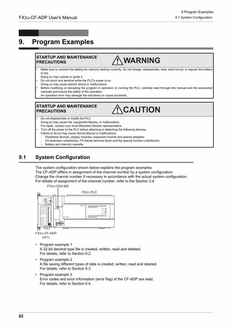
9 Program Examples
9.1 System ConfigurationFX3U-CF-ADP User's Manual
9. Program Examples
9.1 System Configuration
The system configuration shown below explains the program examples.The CF-ADP differs in assignment of the channel number by a system configuration.Change the channel number if necessary in accordance with the actual system configuration. For details of assignment of the channel number, refer to the Section 3.4.
• Program example 1A 32-bit decimal type file is created, written, read and deleted.For details, refer to Section 9.2.
• Program example 2A file saving different types of data is created, written, read and deleted.For details, refer to Section 9.3.
• Program example 3Error codes and error information (error flag) of the CF-ADP are read.For details, refer to Section 9.4.
STARTUP AND MAINTENANCE PRECAUTIONS
• Make sure to connect the battery for memory backup correctly. Do not charge, disassemble, heat, short-circuit, or expose the batteryto fire.Doing so may rupture or ignite it.
• Do not touch any terminal while the PLC's power is on.Doing so may cause electric shock or malfunctions.
• Before modifying or disrupting the program in operation or running the PLC, carefully read through this manual and the associatedmanuals and ensure the safety of the operation.An operation error may damage the machinery or cause accidents.
STARTUP AND MAINTENANCE PRECAUTIONS
• Do not disassemble or modify the PLC.Doing so may cause fire, equipment failures, or malfunctions.For repair, contact your local Mitsubishi Electric representative.
• Turn off the power to the PLC before attaching or detaching the following devices.Failure to do so may cause device failures or malfunctions.- Peripheral devices, display modules, expansion boards and special adapters- I/O extension units/blocks, FX Series terminal block and the special function units/blocks- Battery and memory cassette
FX3U-CNV-BD
FX3U PLC
FX3U-CF-ADP(ch1)
82
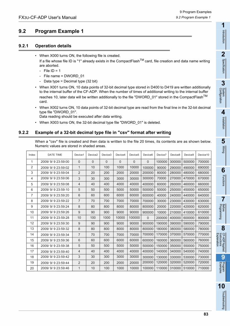
9 Program Examples
9.2 Program Example 1FX3U-CF-ADP User's Manual
1
Introduction
2
Specification
3
System
C
onfiguration
4
Installation
5
Wiring
6
Functions
7
Before
Program
ming
8
CF-A
DP
Applied
Instructions E
xplanation
9
Program
E
xamples
10
Troubleshooting
9.2 Program Example 1
9.2.1 Operation details
• When X000 turns ON, the following file is created.
If a file whose file ID is "1" already exists in the CompactFlashTM card, file creation and data name writing are aborted.
- File ID = 1
- File name = DWORD_01
- Data type = Decimal type (32 bit)
• When X001 turns ON, 10 data points of 32-bit decimal type stored in D400 to D419 are written additionally to the internal buffer of the CF-ADP. When the number of times of additional writing to the internal buffer
reaches 10, later data will be written additionally to the file "DWORD_01" stored in the CompactFlashTM card.
• When X002 turns ON, 10 data points of 32-bit decimal type are read from the final line in the 32-bit decimal type file "DWORD_01".Data reading should be executed after data writing.
• When X003 turns ON, the 32-bit decimal type file "DWORD_01" is deleted.
9.2.2 Example of a 32-bit decimal type file in "csv" format after writing
When a "csv" file is created and then data is written to the file 20 times, its contents are as shown below.Numeric values are stored in shaded areas.
700000
690000680000670000
660000650000
640000
630000
620000
610000
800000790000780000770000
760000
750000740000
730000720000
710000
02009/ 9/ 9 23:59:00 0
2009/ 9/ 9 23:59:28
0 0 0 0 100000 300000 500000
1 10 100 1000 100002 20 200 2000 20000
3 30 300 3000 30000
4 40 400 4000 40000
5 50 500 5000 50000
6 60 600 6000 60000
7 70 700 7000 70000
8 80 800 8000 80000
9 90 900 9000 90000
9 90 900 9000 900008 80 800 8000 80000
7 70 700 7000 700006 60 600 6000 600005 50 500 5000 50000
4 40 400 4000 400003 30 300 3000 30000
2 20 200 2000 200001 10 100 1000 10000
10 100 1000 10000 100000
2009/ 9/ 9 23:59:022009/ 9/ 9 23:59:042009/ 9/ 9 23:59:06
2009/ 9/ 9 23:59:082009/ 9/ 9 23:59:10
2009/ 9/ 9 23:59:202009/ 9/ 9 23:59:22
2009/ 9/ 9 23:59:24
2009/ 9/ 9 23:59:26
2009/ 9/ 9 23:59:302009/ 9/ 9 23:59:32
2009/ 9/ 9 23:59:342009/ 9/ 9 23:59:362009/ 9/ 9 23:59:38
2009/ 9/ 9 23:59:402009/ 9/ 9 23:59:42
2009/ 9/ 9 23:59:442009/ 9/ 9 23:59:46
100000 90000 290000 490000200000 80000 280000 480000300000 70000 270000 470000
400000 60000 260000 460000500000 50000 250000 450000
600000 40000 240000 440000
700000 30000 230000 430000
800000 20000 220000 420000
900000 10000 210000 4100000 200000 400000 600000
900000 190000 390000 590000800000 180000 380000 580000700000 170000 370000 570000
600000 160000 360000 560000500000 150000 350000 550000400000 140000 340000 540000
300000 130000 330000 530000200000 120000 320000 520000
100000 110000 310000 510000
Index DATE TIME Device1 Device7Device6 Device10Device8 Device9Device5Device4Device3Device2
123
4
56
7
8
9
10111213
14
1516
17
18
19
20
83
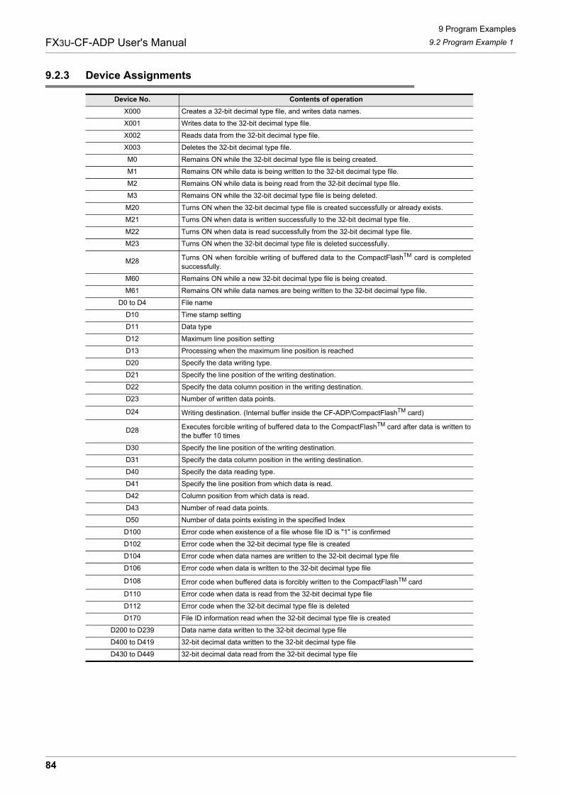
9 Program Examples
9.2 Program Example 1FX3U-CF-ADP User's Manual
9.2.3 Device Assignments
Device No. Contents of operation
X000 Creates a 32-bit decimal type file, and writes data names.
X001 Writes data to the 32-bit decimal type file.
X002 Reads data from the 32-bit decimal type file.
X003 Deletes the 32-bit decimal type file.
M0 Remains ON while the 32-bit decimal type file is being created.
M1 Remains ON while data is being written to the 32-bit decimal type file.
M2 Remains ON while data is being read from the 32-bit decimal type file.
M3 Remains ON while the 32-bit decimal type file is being deleted.
M20 Turns ON when the 32-bit decimal type file is created successfully or already exists.
M21 Turns ON when data is written successfully to the 32-bit decimal type file.
M22 Turns ON when data is read successfully from the 32-bit decimal type file.
M23 Turns ON when the 32-bit decimal type file is deleted successfully.
M28 Turns ON when forcible writing of buffered data to the CompactFlashTM card is completedsuccessfully.
M60 Remains ON while a new 32-bit decimal type file is being created.
M61 Remains ON while data names are being written to the 32-bit decimal type file.
D0 to D4 File name
D10 Time stamp setting
D11 Data type
D12 Maximum line position setting
D13 Processing when the maximum line position is reached
D20 Specify the data writing type.
D21 Specify the line position of the writing destination.
D22 Specify the data column position in the writing destination.
D23 Number of written data points.
D24 Writing destination. (Internal buffer inside the CF-ADP/CompactFlashTM card)
D28 Executes forcible writing of buffered data to the CompactFlashTM card after data is written tothe buffer 10 times
D30 Specify the line position of the writing destination.
D31 Specify the data column position in the writing destination.
D40 Specify the data reading type.
D41 Specify the line position from which data is read.
D42 Column position from which data is read.
D43 Number of read data points.
D50 Number of data points existing in the specified Index
D100 Error code when existence of a file whose file ID is "1" is confirmed
D102 Error code when the 32-bit decimal type file is created
D104 Error code when data names are written to the 32-bit decimal type file
D106 Error code when data is written to the 32-bit decimal type file
D108 Error code when buffered data is forcibly written to the CompactFlashTM card
D110 Error code when data is read from the 32-bit decimal type file
D112 Error code when the 32-bit decimal type file is deleted
D170 File ID information read when the 32-bit decimal type file is created
D200 to D239 Data name data written to the 32-bit decimal type file
D400 to D419 32-bit decimal data written to the 32-bit decimal type file
D430 to D449 32-bit decimal data read from the 32-bit decimal type file
84
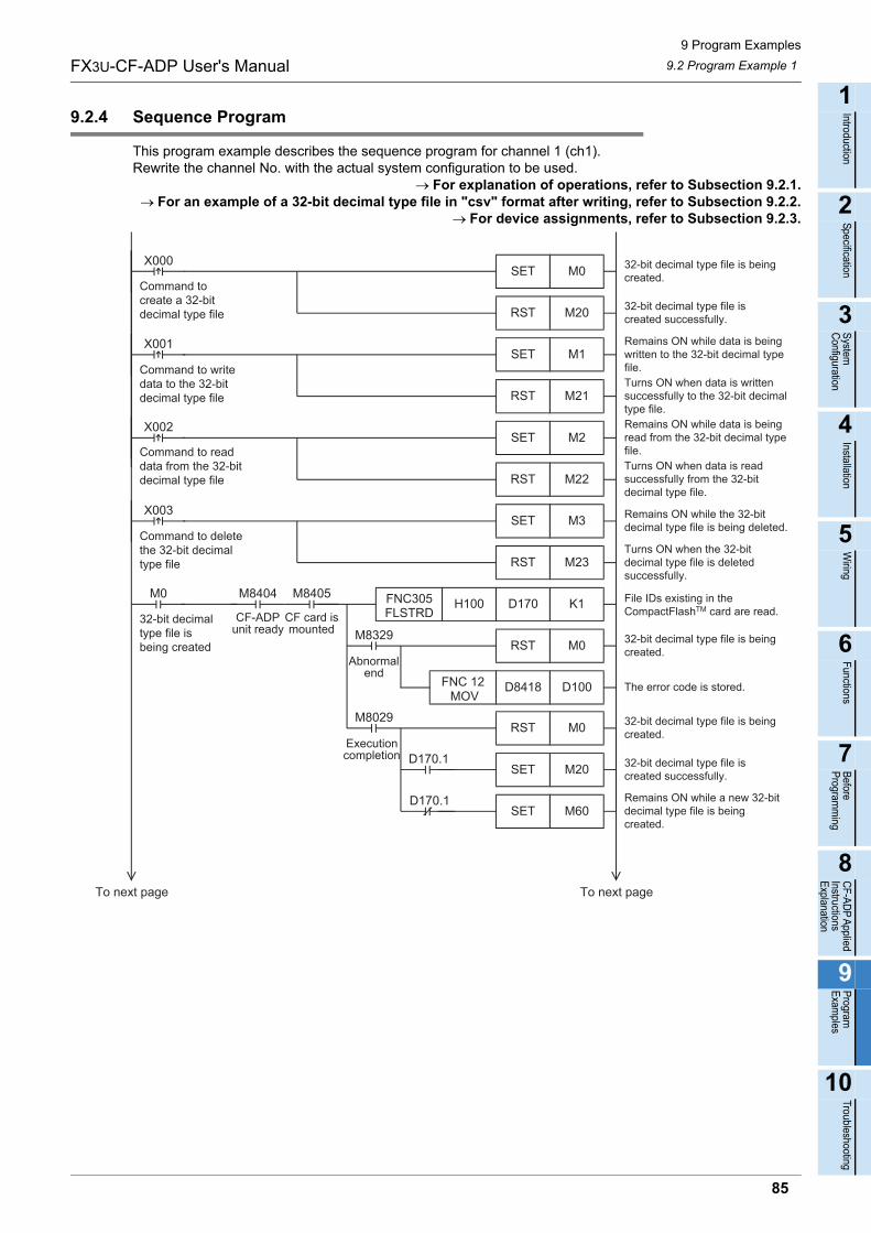
9 Program Examples
9.2 Program Example 1FX3U-CF-ADP User's Manual
1
Introduction
2
Specification
3
System
C
onfiguration
4
Installation
5
Wiring
6
Functions
7
Before
Program
ming
8
CF-A
DP
Applied
Instructions E
xplanation
9
Program
E
xamples
10
Troubleshooting
9.2.4 Sequence Program
This program example describes the sequence program for channel 1 (ch1).Rewrite the channel No. with the actual system configuration to be used.
For explanation of operations, refer to Subsection 9.2.1.For an example of a 32-bit decimal type file in "csv" format after writing, refer to Subsection 9.2.2.
For device assignments, refer to Subsection 9.2.3.
M1SET
M21RST
M0SETX000 32-bit decimal type file is being
created.
32-bit decimal type file is beingcreated.
Command tocreate a 32-bitdecimal type file
D100D8418 The error code is stored.
32-bit decimal type file is beingcreated.
32-bit decimal type file iscreated successfully.
Remains ON while a new 32-bitdecimal type file is beingcreated.
M20RST32-bit decimal type file iscreated successfully.
Remains ON while data is beingwritten to the 32-bit decimal typefile.Turns ON when data is writtensuccessfully to the 32-bit decimaltype file.
X001
M2SET
M22RST
Remains ON while data is beingread from the 32-bit decimal typefile.Turns ON when data is readsuccessfully from the 32-bitdecimal type file.
X002
M3SET
M23RST
Remains ON while the 32-bitdecimal type file is being deleted.
Turns ON when the 32-bitdecimal type file is deletedsuccessfully.
X003
Command to writedata to the 32-bitdecimal type file
Command to readdata from the 32-bitdecimal type file
Command to deletethe 32-bit decimaltype file
K1D170H100FNC305FLSTRD
M8405
CF card ismounted
M0 M8404
CF-ADPunit ready
32-bit decimaltype file isbeing created
File IDs existing in theCompactFlashTM card are read.
FNC 12 MOV
M20SET
M60SET
M0RST
M0RST
M8029
M8329
Executioncompletion
Abnormalend
D170.1
D170.1
To next pageTo next page
85
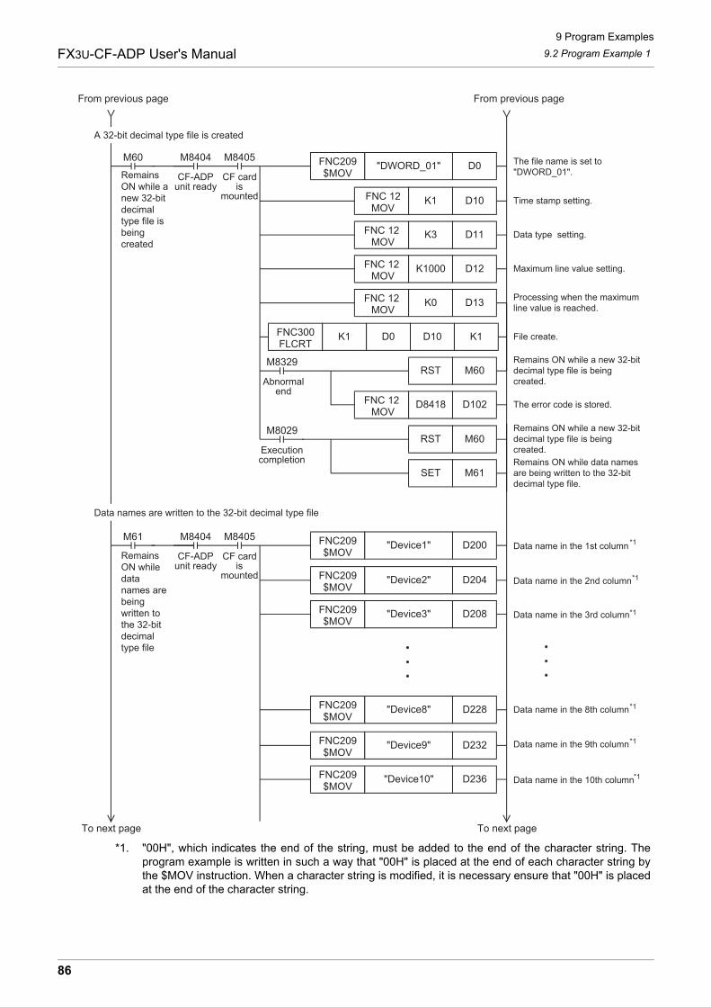
9 Program Examples
9.2 Program Example 1FX3U-CF-ADP User's Manual
*1. "00H", which indicates the end of the string, must be added to the end of the character string. Theprogram example is written in such a way that "00H" is placed at the end of each character string bythe $MOV instruction. When a character string is modified, it is necessary ensure that "00H" is placedat the end of the character string.
Time stamp setting.
D11K3
D12K1000FNC 12 MOV
Data type setting.
Processing when the maximumline value is reached.
File create.
Maximum line value setting.
D0"DWORD_01"FNC209$MOV
M8405
CF cardis
mounted
M60 M8404
CF-ADPunit ready
RemainsON while anew 32-bitdecimaltype file isbeingcreated
The file name is set to"DWORD_01".
FNC 12 MOV
D10K1 FNC 12 MOV
D13K0FNC 12 MOV
K1D10D0FNC300FLCRT
K1
Remains ON while a new 32-bitdecimal type file is beingcreated.
D102D8418 The error code is stored.
Remains ON while a new 32-bitdecimal type file is beingcreated.
FNC 12 MOV
M61SET
M60RST
M60RST
M8029
M8329
D200"Device1"FNC209$MOV
M8405
CF cardis
mounted
M61 M8404
CF-ADPunit ready
RemainsON whiledatanames arebeingwritten tothe 32-bitdecimaltype file
Data name in the 1st column*1
*1
*1
*1
*1
*1
D204"Device2"FNC209$MOV
Data name in the 2nd column
D208"Device3"FNC209$MOV
Data name in the 3rd column
D228"Device8"FNC209$MOV
D232"Device9"FNC209$MOV
D236"Device10"FNC209$MOV
Data name in the 8th column
Data name in the 9th column
Data name in the 10th column
A 32-bit decimal type file is created
Data names are written to the 32-bit decimal type file
To next pageTo next page
From previous pageFrom previous page
Executioncompletion
Abnormalend
Remains ON while data namesare being written to the 32-bitdecimal type file.
86
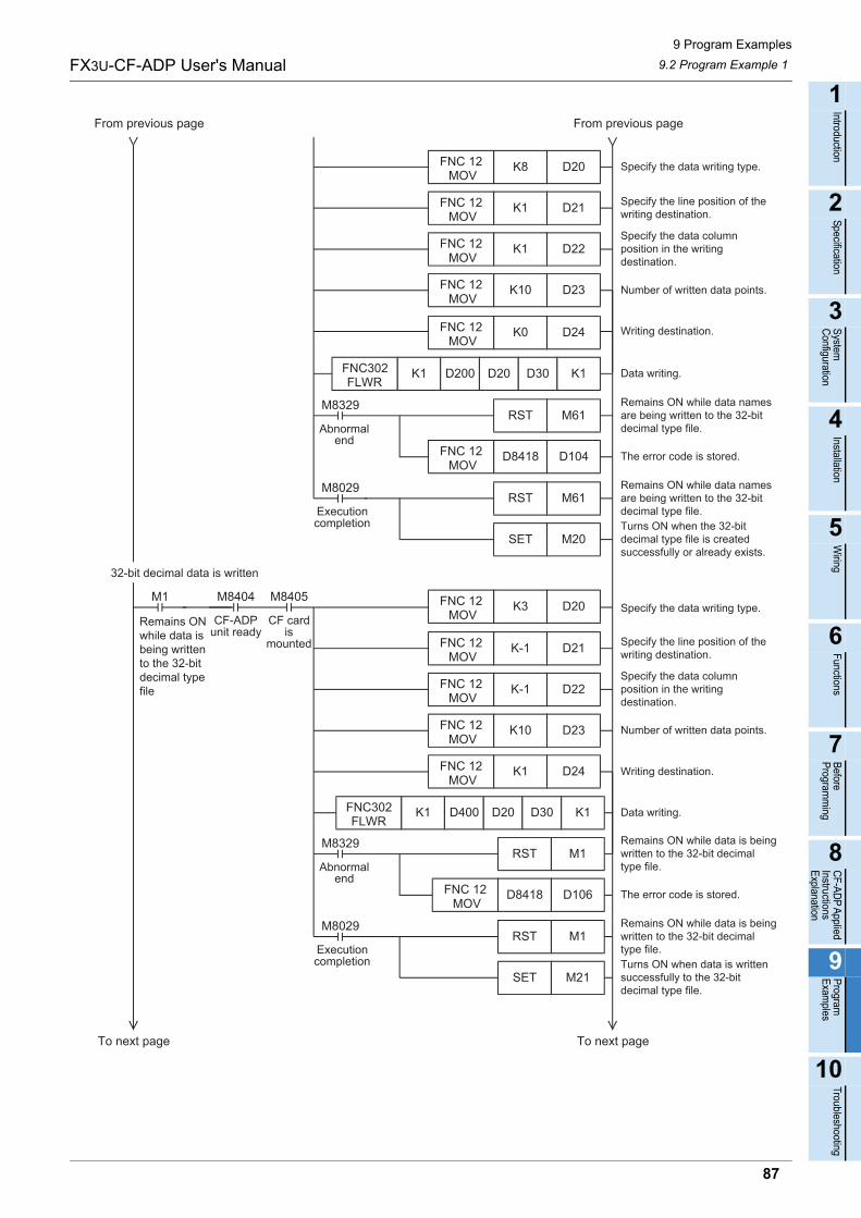
9 Program Examples
9.2 Program Example 1FX3U-CF-ADP User's Manual
1
Introduction
2
Specification
3
System
C
onfiguration
4
Installation
5
Wiring
6
Functions
7
Before
Program
ming
8
CF-A
DP
Applied
Instructions E
xplanation
9
Program
E
xamples
10
Troubleshooting
Specify the data writing type.
D21K1
D22K1FNC 12 MOV
Specify the line position of thewriting destination.
Number of written data points.
Writing destination.
Specify the data columnposition in the writingdestination.
FNC 12 MOV
D20K8FNC 12 MOV
D23K10FNC 12 MOV
D104D8418 The error code is stored.FNC 12 MOV
M20
M61RST
M61RST
M8029
M8329
D24K0FNC 12 MOV
Data writing.
SET
From previous pageFrom previous page
To next pageTo next page
Remains ON while data namesare being written to the 32-bitdecimal type file.
Remains ON while data namesare being written to the 32-bitdecimal type file.Turns ON when the 32-bitdecimal type file is createdsuccessfully or already exists.
Specify the line position of thewriting destination.
D22K-1
D23K10FNC 12 MOV
Specify the data columnposition in the writingdestination.
Writing destination.
Data writing.
Number of written data points.
M8405
CF cardis
mounted
M1 M8404
CF-ADPunit ready
Remains ONwhile data isbeing writtento the 32-bitdecimal typefile
Specify the data writing type.
FNC 12 MOV
D21K-1FNC 12 MOV
D24K1FNC 12 MOV
FNC302FLWR
K1
Remains ON while data is beingwritten to the 32-bit decimaltype file.
D106D8418 The error code is stored.
Remains ON while data is beingwritten to the 32-bit decimaltype file.Turns ON when data is writtensuccessfully to the 32-bitdecimal type file.
FNC 12 MOV
M21SET
M1RST
M1RST
M8029
M8329
D20K3FNC 12 MOV
D400 D20 D30 K1
32-bit decimal data is written
Executioncompletion
Abnormalend
Executioncompletion
Abnormalend
FNC302FLWR
K1 D200 D20 D30 K1
87
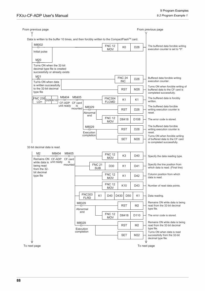
9 Program Examples
9.2 Program Example 1FX3U-CF-ADP User's Manual
The buffered data forcible writingexecution counter is set to "0".
M8002
Initial pulse
D28K0FNC 12 MOV
M20
Buffered data forcible writingexecution counter.
M21
Turns ON when the 32-bitdecimal type file is createdsuccessfully or already exists
D28FNC 24 INC
M28RST
The buffered data is forciblywritten.
FNC304FLCMD
The buffered data forciblewriting execution counter isreset.
D108D8418 The error code is stored.
The buffered data forciblewriting execution counter isreset.Turns ON when forcible writingof buffered data to the CF cardis completed successfully.
FNC 12 MOV
M28SET
D28RST
D28RST
M8029
M8329
M8405
CF cardis
mounted
M8404
CF-ADPunit ready
K1K1D28FNC 230
LD=K10
From previous pageFrom previous page
To next pageTo next page
Specify the line position fromwhich data is read. (Final line)
D42K1
D43K10FNC 12 MOV
Column position from whichdata is read.
Data reading.
Number of read data points.
M8405
CF cardis
mounted
M2 M8404
CF-ADPunit ready
Remains ONwhile data isbeing readfrom the 32-bit decimaltype file
Specify the data reading type.
FNC 12 MOV
D41K1
FNC303FLRD
K1
Remains ON while data is beingread from the 32-bit decimaltype file.
D110D8418 The error code is stored.
Remains ON while data is beingread from the 32-bit decimaltype file.Turns ON when data is readsuccessfully from the 32-bitdecimal type file.
FNC 12 MOV
M22SET
M2RST
M2RST
M8029
M8329
D40K3FNC 12 MOV
D40 D430 D50 K1
Data is written to the buffer 10 times, and then forcibly written to the CompactFlashTM card.
32-bit decimal data is read.
Turns ON when datais written successfullyto the 32-bit decimaltype file
Turns ON when forcible writing ofbuffered data to the CF card iscompleted successfully.
FNC 21 SUB
D30
Executioncompletion
Abnormalend
Executioncompletion
Abnormalend
88
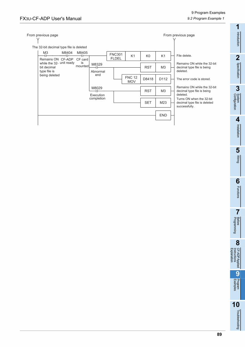
9 Program Examples
9.2 Program Example 1FX3U-CF-ADP User's Manual
1
Introduction
2
Specification
3
System
C
onfiguration
4
Installation
5
Wiring
6
Functions
7
Before
Program
ming
8
CF-A
DP
Applied
Instructions E
xplanation
9
Program
E
xamples
10
Troubleshooting
File delete.M8405
CF cardis
mounted
M3 M8404
CF-ADPunit ready
Remains ONwhile the 32-bit decimaltype file isbeing deleted
Remains ON while the 32-bitdecimal type file is beingdeleted.
D112D8418 The error code is stored.
Remains ON while the 32-bitdecimal type file is beingdeleted.Turns ON when the 32-bitdecimal type file is deletedsuccessfully.
FNC 12 MOV
M23SET
M3RST
M3RST
M8029
M8329
K1K0K1FNC301FLDEL
END
From previous pageFrom previous page
The 32-bit decimal type file is deleted
Executioncompletion
Abnormalend
89
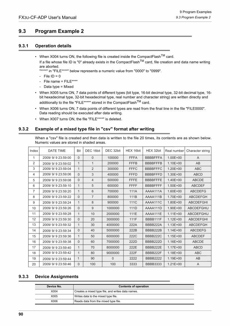
9 Program Examples
9.3 Program Example 2FX3U-CF-ADP User's Manual
9.3 Program Example 2
9.3.1 Operation details
• When X004 turns ON, the following file is created inside the CompactFlashTM card.
If a file whose file ID is "0" already exists in the CompactFlashTM card, file creation and data name writing are aborted."****" in "FILE****" below represents a numeric value from "0000" to "0999".
- File ID = 0
- File name = FILE****
- Data type = Mixed
• When X005 turns ON, 7 data points of different types (bit type, 16-bit decimal type, 32-bit decimal type, 16-bit hexadecimal type, 32-bit hexadecimal type, real number and character string) are written directly and
additionally to the file "FILE****" stored in the CompactFlashTM card.
• When X006 turns ON, 7 data points of different types are read from the final line in the file "FILE0000". Data reading should be executed after data writing.
• When X007 turns ON, the file "FILE****" is deleted.
9.3.2 Example of a mixed type file in "csv" format after writing
When a "csv" file is created and then data is written to the file 20 times, its contents are as shown below.Numeric values are stored in shaded areas.
9.3.3 Device Assignments
Device No. Contents of operation
X004 Creates a mixed type file, and writes data names.
X005 Writes data to the mixed type file.
X006 Reads data from the mixed type file.
1 10 2000000 1.11E+00111E AAAA111E ABCDEFGHIJ0 20 3000000 1.12E+00111F BBBB111F ABCDEFGHI1 30 4000000 1.13E+00222A BBBB222A ABCDEFGH0 40 5000000 1.14E+00222B BBBB222B ABCDEFG
1 50 6000000 1.15E+00222C BBBB222C ABCDEF0 60 7000000 1.16E+00222D BBBB222D ABCDE
1 70 8000000 1.17E+00222E BBBB222E ABCD1 80 9000000 1.18E+00222F BBBB222F ABC1 90 0 1.19E+002222 BBBB2222 AB
0 100 100 1.21E+003333 BBBB3333 A
2 300000 1.20E+00FFFC BBBBFFFC ABC
0 3 400000 1.30E+00FFFD BBBBFFFD ABCD
0 4 500000 1.40E+00FFFE BBBBFFFE ABCDE
1 5 600000 1.50E+00FFFF BBBBFFFF ABCDEF
1 6 700000 1.60E+00111A AAAA111A ABCDEFG
0 7 800000 1.70E+00111B AAAA111B ABCDEFGH
1 8 900000 1.80E+00111C AAAA111C ABCDEFGHI
0 9 1000000 1.90E+00111D AAAA111D ABCDEFGHIJ
0 0 100000 1.00E+00FFFA BBBBFFFA A
1 1 200000 1.10E+00FFFB BBBBFFFB AB
1
DATE TIMEIndex Bit Character stringReal numberDEC 16bit
123
4
56
7
8
9
10
2009/ 9/ 9 23:59:00
111213
14
1516
17
18
19
20
2009/ 9/ 9 23:59:28
2009/ 9/ 9 23:59:022009/ 9/ 9 23:59:042009/ 9/ 9 23:59:06
2009/ 9/ 9 23:59:082009/ 9/ 9 23:59:10
2009/ 9/ 9 23:59:202009/ 9/ 9 23:59:22
2009/ 9/ 9 23:59:24
2009/ 9/ 9 23:59:26
2009/ 9/ 9 23:59:302009/ 9/ 9 23:59:32
2009/ 9/ 9 23:59:342009/ 9/ 9 23:59:362009/ 9/ 9 23:59:38
2009/ 9/ 9 23:59:402009/ 9/ 9 23:59:42
2009/ 9/ 9 23:59:442009/ 9/ 9 23:59:46
DEC 32bit HEX 16bit HEX 32bit
90
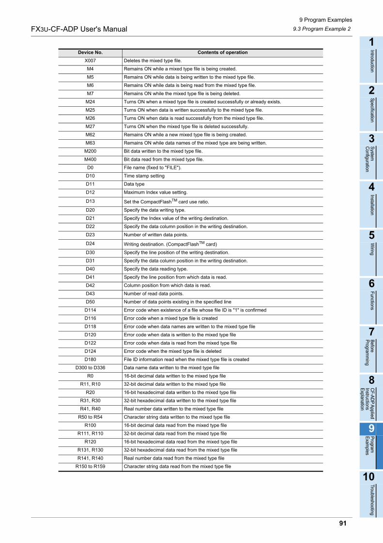
9 Program Examples
9.3 Program Example 2FX3U-CF-ADP User's Manual
1
Introduction
2
Specification
3
System
C
onfiguration
4
Installation
5
Wiring
6
Functions
7
Before
Program
ming
8
CF-A
DP
Applied
Instructions E
xplanation
9
Program
E
xamples
10
Troubleshooting
X007 Deletes the mixed type file.
M4 Remains ON while a mixed type file is being created.
M5 Remains ON while data is being written to the mixed type file.
M6 Remains ON while data is being read from the mixed type file.
M7 Remains ON while the mixed type file is being deleted.
M24 Turns ON when a mixed type file is created successfully or already exists.
M25 Turns ON when data is written successfully to the mixed type file.
M26 Turns ON when data is read successfully from the mixed type file.
M27 Turns ON when the mixed type file is deleted successfully.
M62 Remains ON while a new mixed type file is being created.
M63 Remains ON while data names of the mixed type are being written.
M200 Bit data written to the mixed type file.
M400 Bit data read from the mixed type file.
D0 File name (fixed to "FILE").
D10 Time stamp setting
D11 Data type
D12 Maximum Index value setting.
D13 Set the CompactFlashTM card use ratio.
D20 Specify the data writing type.
D21 Specify the Index value of the writing destination.
D22 Specify the data column position in the writing destination.
D23 Number of written data points.
D24 Writing destination. (CompactFlashTM card)
D30 Specify the line position of the writing destination.
D31 Specify the data column position in the writing destination.
D40 Specify the data reading type.
D41 Specify the line position from which data is read.
D42 Column position from which data is read.
D43 Number of read data points.
D50 Number of data points existing in the specified line
D114 Error code when existence of a file whose file ID is "1" is confirmed
D116 Error code when a mixed type file is created
D118 Error code when data names are written to the mixed type file
D120 Error code when data is written to the mixed type file
D122 Error code when data is read from the mixed type file
D124 Error code when the mixed type file is deleted
D180 File ID information read when the mixed type file is created
D300 to D336 Data name data written to the mixed type file
R0 16-bit decimal data written to the mixed type file
R11, R10 32-bit decimal data written to the mixed type file
R20 16-bit hexadecimal data written to the mixed type file
R31, R30 32-bit hexadecimal data written to the mixed type file
R41, R40 Real number data written to the mixed type file
R50 to R54 Character string data written to the mixed type file
R100 16-bit decimal data read from the mixed type file
R111, R110 32-bit decimal data read from the mixed type file
R120 16-bit hexadecimal data read from the mixed type file
R131, R130 32-bit hexadecimal data read from the mixed type file
R141, R140 Real number data read from the mixed type file
R150 to R159 Character string data read from the mixed type file
Device No. Contents of operation
91
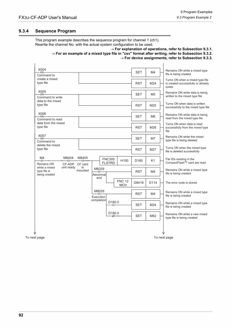
9 Program Examples
9.3 Program Example 2FX3U-CF-ADP User's Manual
9.3.4 Sequence Program
This program example describes the sequence program for channel 1 (ch1).Rewrite the channel No. with the actual system configuration to be used.
For explanation of operations, refer to Subsection 9.3.1.For an example of a mixed type file in "csv" format after writing, refer to Subsection 9.3.2.
For device assignments, refer to Subsection 9.3.3.
M5SET
M25RST
M4SETX004 Remains ON while a mixed type
file is being created
Remains ON while a mixed typefile is being created
Command tocreate a mixedtype file
D114D8418 The error code is stored.
Remains ON while a mixed typefile is being created
Remains ON while a mixed typefile is being created
Remains ON while a new mixedtype file is being created
M24RSTTurns ON when a mixed type fileis created successfully or alreadyexists
Remains ON while data is beingwritten to the mixed type file
Turns ON when data is writtensuccessfully to the mixed type file
X005
M6SET
M26RST
Remains ON while data is beingread from the mixed type file
Turns ON when data is readsuccessfully from the mixed typefile
X006
M7SET
M27RST
Remains ON while the mixedtype file is being deleted
Turns ON when the mixed typefile is deleted successfully
X007
Command to writedata to the mixedtype file
Command to readdata from the mixedtype file
Command todelete the mixedtype file
K1D180H100FNC305FLSTRD
M8405
CF cardis
mounted
M4 M8404
CF-ADPunit ready
Remains ONwhile a mixedtype file isbeing created
File IDs existing in theCompactFlashTM card are read.
FNC 12 MOV
M24SET
M62SET
M4RST
M4RST
M8029
M8329
D180.0
D180.0
To next pageTo next page
Executioncompletion
Abnormalend
92
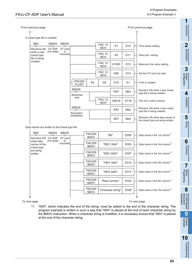
9 Program Examples
9.3 Program Example 2FX3U-CF-ADP User's Manual
1
Introduction
2
Specification
3
System
C
onfiguration
4
Installation
5
Wiring
6
Functions
7
Before
Program
ming
8
CF-A
DP
Applied
Instructions E
xplanation
9
Program
E
xamples
10
Troubleshooting
*1. "00H", which indicates the end of the string, must be added to the end of the character string. Theprogram example is written in such a way that "00H" is placed at the end of each character string bythe $MOV instruction. When a character string is modified, it is necessary ensure that "00H" is placedat the end of the character string.
Time stamp setting.
D11K0
D12K1000FNC 12 MOV
Data type setting.
Set the CF card use ratio.
A file is created.
Maximum line value setting.
M8405
CF cardis
mounted
M62 M8404
CF-ADPunit ready
Remains ONwhile a newmixed typefile is beingcreated
FNC 12 MOV
D10K1FNC 12 MOV
D13K80FNC 12 MOV
K1D10D0FNC305FLCRT
K0
Remains ON while a new mixedtype file is being created.
D116D8418 The error code is stored.
Remains ON while a new mixedtype file is being created.
Remains ON while data names ofthe mixed type are being written.
FNC 12 MOV
M63SET
M62RST
M62RST
M8029
M8329
D300"Bit"FNC209$MOV
M8405
CF cardis
mounted
M63 M8404
CF-ADPunit ready
Remains ONwhile datanames of themixed typeare beingwritten
Data name in the 1st column
D302"DEC 16bit"FNC209$MOV
Data name in the 2nd column
D307"DEC 32bit"FNC209$MOV
Data name in the 3rd column
D312"HEX 16bit"FNC209$MOV
Data name in the 4th column
D317FNC209$MOV
Data name in the 5th column
D322"Real number"FNC209$MOV
Data name in the 6th column
D328"Character string"FNC209$MOV
Data name in the 7th column
A mixed type file is created
Data names are written to the mixed type file.
"HEX 32bit"
To next pageTo next page
From previous pageFrom previous page
Executioncompletion
Abnormalend
*1
*1
*1
*1
*1
*1
*1
93
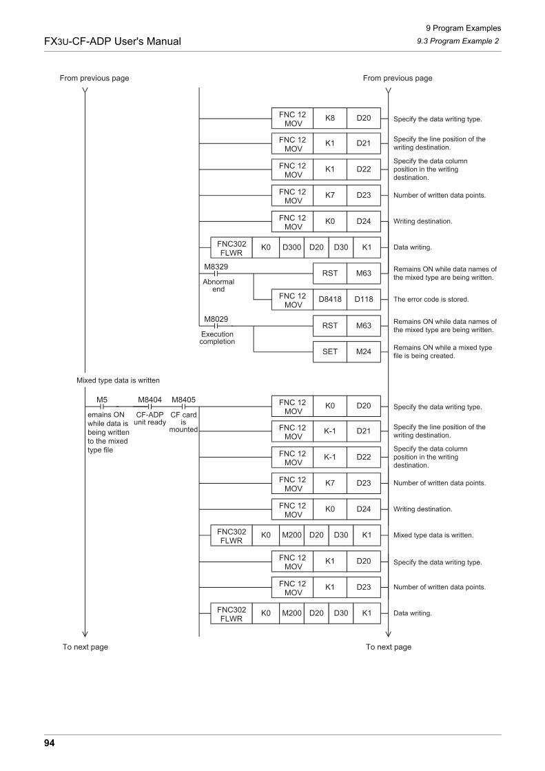
9 Program Examples
9.3 Program Example 2FX3U-CF-ADP User's Manual
Specify the line position of thewriting destination.
D22K1
D23K7FNC 12 MOV
Specify the data columnposition in the writingdestination.
Writing destination.
Data writing.
Number of written data points.
Specify the data writing type.
FNC 12 MOV
D21K1FNC 12 MOV
D24K0FNC 12 MOV
FNC302FLWR
K0
Remains ON while data names ofthe mixed type are being written.
D118D8418 The error code is stored.
Remains ON while data names ofthe mixed type are being written.
Remains ON while a mixed typefile is being created.
FNC 12 MOV
M24SET
M63RST
M63RST
M8029
M8329
D20K8FNC 12 MOV
D300 D20 D30 K1
Specify the line position of thewriting destination.
D22K-1
D23K7FNC 12 MOV
Specify the data columnposition in the writingdestination.
Writing destination.
Mixed type data is written.
Number of written data points.
M8405
CF cardis
mounted
M5 M8404
CF-ADPunit ready
emains ONwhile data isbeing writtento the mixedtype file
Specify the data writing type.
FNC 12 MOV
D21K-1FNC 12 MOV
D24K0FNC 12 MOV
FNC302FLWR
K0
D20K0FNC 12 MOV
M200 D20 D30 K1
From previous pageFrom previous page
Mixed type data is written
Number of written data points.
Data writing.
Specify the data writing type.
D23K1FNC 12 MOV
FNC302FLWR
K0
D20K1FNC 12 MOV
M200 D20 D30 K1
To next pageTo next page
Executioncompletion
Abnormalend
94
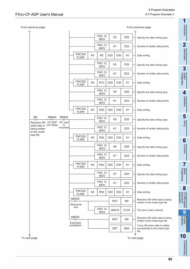
9 Program Examples
9.3 Program Example 2FX3U-CF-ADP User's Manual
1
Introduction
2
Specification
3
System
C
onfiguration
4
Installation
5
Wiring
6
Functions
7
Before
Program
ming
8
CF-A
DP
Applied
Instructions E
xplanation
9
Program
E
xamples
10
Troubleshooting
From previous pageFrom previous page
To next pageTo next page
Number of written data points.
Data writing.
Specify the data writing type.
D23K1FNC 12 MOV
FNC302FLWR
K0
D20K2FNC 12 MOV
R0 D20 D30 K1
Number of written data points.
Data writing.
Specify the data writing type.
D23K1FNC 12 MOV
FNC302FLWR
K0
D20K3FNC 12 MOV
R10 D20 D30 K1
Number of written data points.
Data writing.
Specify the data writing type.
D23K1FNC 12 MOV
FNC302FLWR
K0
D20K4FNC 12 MOV
R20 D20 D30 K1
Number of written data points.
Data writing.
Specify the data writing type.
D23K1FNC 12 MOV
FNC302FLWR
K0
D20K5FNC 12 MOV
R30 D20 D30 K1
Number of written data points.
Data writing.
Specify the data writing type.
D23K1FNC 12 MOV
FNC302FLWR
K0
D20K6FNC 12 MOV
R40 D20 D30 K1
Number of written data points.
Data writing.
Specify the data writing type.
D23K1FNC 12 MOV
FNC302FLWR
K0
D20K7FNC 12 MOV
R50 D20 D30 K1
M8405
CF cardis
mounted
M5 M8404
CF-ADPunit ready
Remains ONwhile data isbeing writtento the mixedtype file
Remains ON while data is beingwritten to the mixed type file
D120D8418 The error code is stored.
Remains ON while data is beingwritten to the mixed type file
Turns ON when data is writtensuccessfully to the mixed typefile.
FNC 12 MOV
M25SET
M5RST
M5RST
M8029
M8329
Executioncompletion
Abnormalend
95
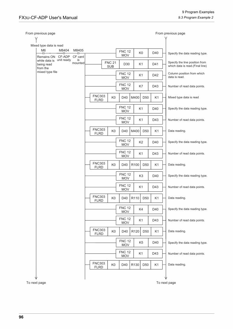
9 Program Examples
9.3 Program Example 2FX3U-CF-ADP User's Manual
Specify the line position fromwhich data is read.(Final line)
D42K1
D43K7FNC 12 MOV
Column position from whichdata is read.
Mixed type data is read
Specify the data reading type.
Number of read data points.
M8405
CF cardis
mounted
M6 M8404
CF-ADPunit ready
Remains ONwhile data isbeing readfrom themixed type file
Specify the data reading type.
FNC 12 MOV
D41K1FNC 21SUB
FNC303FLRD
K0
D40K0FNC 12 MOV
D40 M400 D50 K1
D30
D40K1FNC 12 MOV
D43K1FNC 12 MOV
Number of read data points.
Data reading.FNC303FLRD
K0 D40 M400 D50 K1
Specify the data reading type.D40K2FNC 12 MOV
D43K1FNC 12 MOV
Number of read data points.
Data reading.FNC303FLRD
K0 D40 R100 D50 K1
Specify the data reading type.D40K3FNC 12 MOV
D43K1FNC 12 MOV
Number of read data points.
Data reading.FNC303FLRD
K0 D40 R110 D50 K1
Specify the data reading type.D40K4FNC 12 MOV
D43K1FNC 12 MOV
Number of read data points.
Data reading.FNC303FLRD
K0 D40 R120 D50 K1
From previous pageFrom previous page
Mixed type data is read
Specify the data reading type.D40K5FNC 12 MOV
D43K1FNC 12 MOV
Number of read data points.
Data reading.FNC303FLRD
K0 D40 R130 D50 K1
To next pageTo next page
96
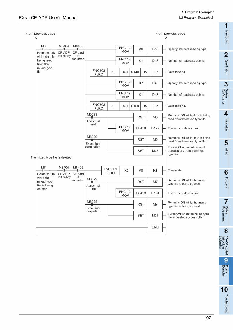
9 Program Examples
9.3 Program Example 2FX3U-CF-ADP User's Manual
1
Introduction
2
Specification
3
System
C
onfiguration
4
Installation
5
Wiring
6
Functions
7
Before
Program
ming
8
CF-A
DP
Applied
Instructions E
xplanation
9
Program
E
xamples
10
Troubleshooting
Specify the data reading type.D40K6FNC 12 MOV
D43K1FNC 12 MOV
Number of read data points.
Data reading.FNC303FLRD
K0 D40 R140 D50 K1
Specify the data reading type.D40K7FNC 12 MOV
D43K1FNC 12 MOV
Number of read data points.
Data reading.FNC303FLRD
K0 D40 R150 D50 K1
M8405
CF cardis
mounted
M6 M8404
CF-ADPunit ready
Remains ONwhile data isbeing readfrom themixed typefile
Remains ON while data is beingread from the mixed type file
D122D8418 The error code is stored.
Remains ON while data is beingread from the mixed type file
Turns ON when data is readsuccessfully from the mixedtype file
FNC 12 MOV
M26SET
M6RST
M6RST
M8029
M8329
File deleteK1K0FNC 301 FLDEL
M8405
CF cardis
mounted
M7 M8404
CF-ADPunit ready
Remains ONwhile themixed typefile is beingdeleted
Remains ON while the mixedtype file is being deleted.
D124D8418 The error code is stored.
Remains ON while the mixedtype file is being deleted
Turns ON when the mixed typefile is deleted successfully
FNC 12 MOV
M27SET
M7RST
M7RST
M8029
M8329
K0
END
From previous pageFrom previous page
The mixed type file is deleted
Executioncompletion
Abnormalend
Executioncompletion
Abnormalend
97
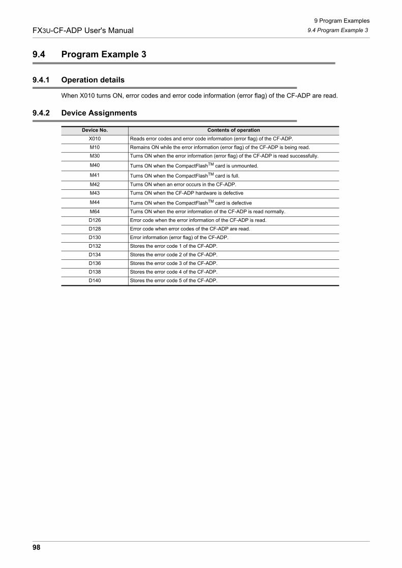
9 Program Examples
9.4 Program Example 3FX3U-CF-ADP User's Manual
9.4 Program Example 3
9.4.1 Operation details
When X010 turns ON, error codes and error code information (error flag) of the CF-ADP are read.
9.4.2 Device Assignments
Device No. Contents of operation
X010 Reads error codes and error code information (error flag) of the CF-ADP.
M10 Remains ON while the error information (error flag) of the CF-ADP is being read.
M30 Turns ON when the error information (error flag) of the CF-ADP is read successfully.
M40 Turns ON when the CompactFlashTM card is unmounted.
M41 Turns ON when the CompactFlashTM card is full.
M42 Turns ON when an error occurs in the CF-ADP.
M43 Turns ON when the CF-ADP hardware is defective
M44 Turns ON when the CompactFlashTM card is defective
M64 Turns ON when the error information of the CF-ADP is read normally.
D126 Error code when the error information of the CF-ADP is read.
D128 Error code when error codes of the CF-ADP are read.
D130 Error information (error flag) of the CF-ADP.
D132 Stores the error code 1 of the CF-ADP.
D134 Stores the error code 2 of the CF-ADP.
D136 Stores the error code 3 of the CF-ADP.
D138 Stores the error code 4 of the CF-ADP.
D140 Stores the error code 5 of the CF-ADP.
98
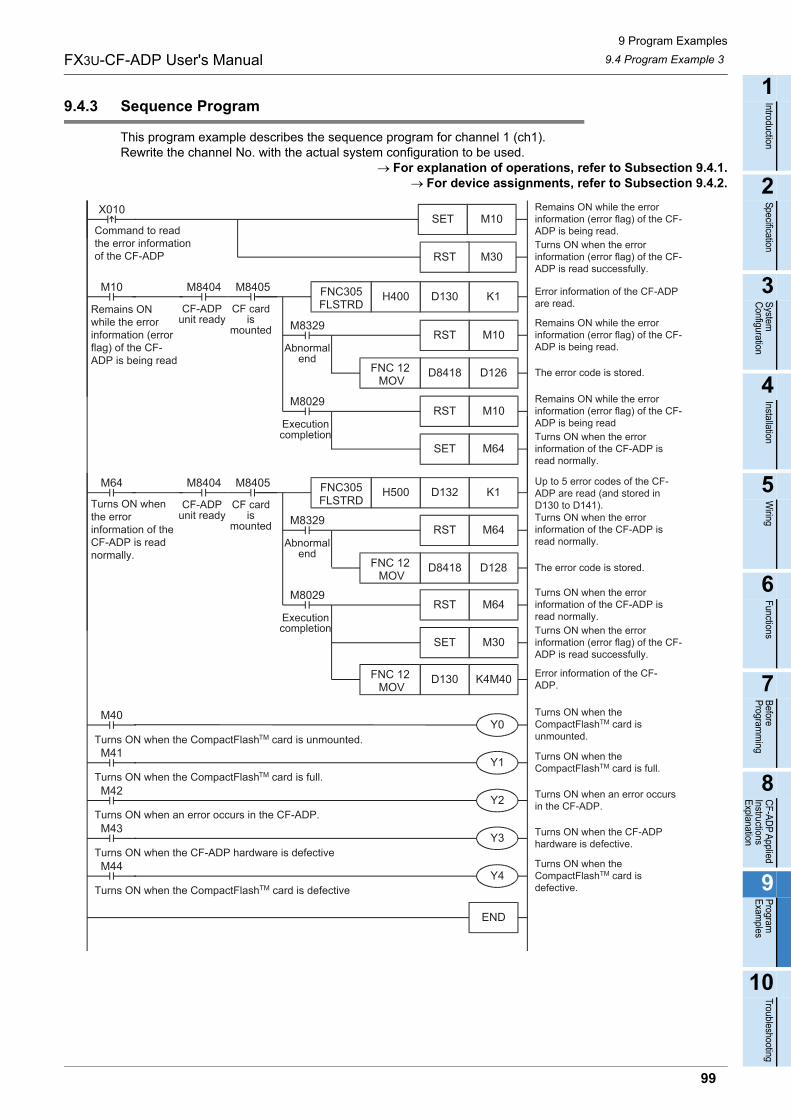
9 Program Examples
9.4 Program Example 3FX3U-CF-ADP User's Manual
1
Introduction
2
Specification
3
System
C
onfiguration
4
Installation
5
Wiring
6
Functions
7
Before
Program
ming
8
CF-A
DP
Applied
Instructions E
xplanation
9
Program
E
xamples
10
Troubleshooting
9.4.3 Sequence Program
This program example describes the sequence program for channel 1 (ch1).Rewrite the channel No. with the actual system configuration to be used.
For explanation of operations, refer to Subsection 9.4.1.For device assignments, refer to Subsection 9.4.2.
M10SETX010 Remains ON while the error
information (error flag) of the CF-ADP is being read.Command to read
the error informationof the CF-ADP M30RST
Turns ON when the errorinformation (error flag) of the CF-ADP is read successfully.
K1D130H400FNC305FLSTRD
M8405
CF cardis
mounted
M10 M8404
CF-ADPunit ready
Remains ONwhile the errorinformation (errorflag) of the CF-ADP is being read
Error information of the CF-ADPare read.
K1D132H500FNC305FLSTRD
M8405
CF cardis
mounted
M64 M8404
CF-ADPunit ready
Turns ON whenthe errorinformation of theCF-ADP is readnormally.
Up to 5 error codes of the CF-ADP are read (and stored inD130 to D141).
END
Y0M40
Turns ON when the CompactFlashTM card is unmounted.
Y1M41
Turns ON when the CompactFlashTM card is full.
Y2M42
Turns ON when an error occurs in the CF-ADP.
Y3M43
Turns ON when the CF-ADP hardware is defective
Y4M44
Turns ON when the CompactFlashTM card is defective
Turns ON when theCompactFlashTM card isunmounted.
Turns ON when theCompactFlashTM card is full.
Turns ON when an error occursin the CF-ADP.
Turns ON when the CF-ADPhardware is defective.
Turns ON when theCompactFlashTM card isdefective.
D126D8418 The error code is stored.
Turns ON when the errorinformation of the CF-ADP isread normally.
FNC 12 MOV
M64SET
M10RST
M10RST
M8029
M8329
D128D8418 The error code is stored.
Turns ON when the errorinformation (error flag) of the CF-ADP is read successfully.
FNC 12 MOV
M30SET
M64RST
M64RST
M8029
M8329
K4M40D130FNC 12 MOV
Error information of the CF-ADP.
Remains ON while the errorinformation (error flag) of the CF-ADP is being read.
Remains ON while the errorinformation (error flag) of the CF-ADP is being read
Turns ON when the errorinformation of the CF-ADP isread normally.
Turns ON when the errorinformation of the CF-ADP isread normally.
Executioncompletion
Abnormalend
Executioncompletion
Abnormalend
99
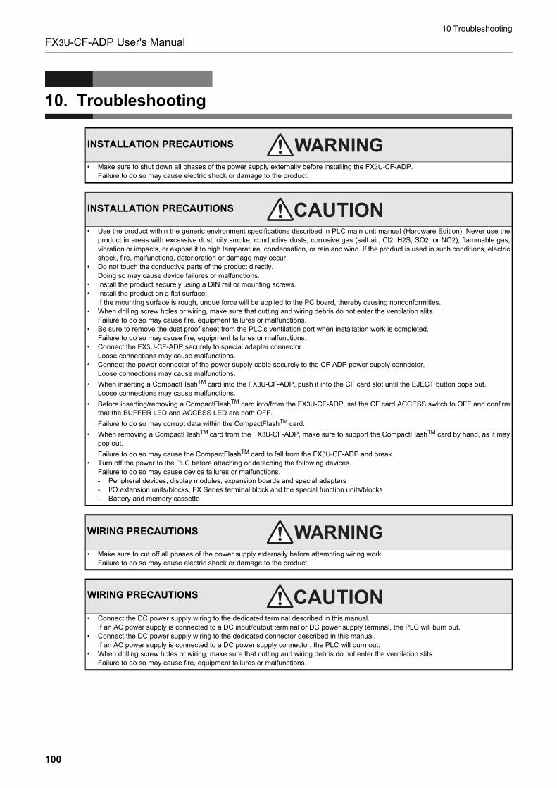
10 Troubleshooting
FX3U-CF-ADP User's Manual
10. Troubleshooting
INSTALLATION PRECAUTIONS
• Make sure to shut down all phases of the power supply externally before installing the FX3U-CF-ADP.Failure to do so may cause electric shock or damage to the product.
INSTALLATION PRECAUTIONS
• Use the product within the generic environment specifications described in PLC main unit manual (Hardware Edition). Never use theproduct in areas with excessive dust, oily smoke, conductive dusts, corrosive gas (salt air, Cl2, H2S, SO2, or NO2), flammable gas,vibration or impacts, or expose it to high temperature, condensation, or rain and wind. If the product is used in such conditions, electricshock, fire, malfunctions, deterioration or damage may occur.
• Do not touch the conductive parts of the product directly.Doing so may cause device failures or malfunctions.
• Install the product securely using a DIN rail or mounting screws.• Install the product on a flat surface.
If the mounting surface is rough, undue force will be applied to the PC board, thereby causing nonconformities.• When drilling screw holes or wiring, make sure that cutting and wiring debris do not enter the ventilation slits.
Failure to do so may cause fire, equipment failures or malfunctions.• Be sure to remove the dust proof sheet from the PLC's ventilation port when installation work is completed.
Failure to do so may cause fire, equipment failures or malfunctions.• Connect the FX3U-CF-ADP securely to special adapter connector.
Loose connections may cause malfunctions.• Connect the power connector of the power supply cable securely to the CF-ADP power supply connector.
Loose connections may cause malfunctions.
• When inserting a CompactFlashTM card into the FX3U-CF-ADP, push it into the CF card slot until the EJECT button pops out.Loose connections may cause malfunctions.
• Before inserting/removing a CompactFlashTM card into/from the FX3U-CF-ADP, set the CF card ACCESS switch to OFF and confirmthat the BUFFER LED and ACCESS LED are both OFF.
Failure to do so may corrupt data within the CompactFlashTM card.
• When removing a CompactFlashTM card from the FX3U-CF-ADP, make sure to support the CompactFlashTM card by hand, as it maypop out.
Failure to do so may cause the CompactFlashTM card to fall from the FX3U-CF-ADP and break.• Turn off the power to the PLC before attaching or detaching the following devices.
Failure to do so may cause device failures or malfunctions.- Peripheral devices, display modules, expansion boards and special adapters- I/O extension units/blocks, FX Series terminal block and the special function units/blocks- Battery and memory cassette
WIRING PRECAUTIONS
• Make sure to cut off all phases of the power supply externally before attempting wiring work.Failure to do so may cause electric shock or damage to the product.
WIRING PRECAUTIONS
• Connect the DC power supply wiring to the dedicated terminal described in this manual.If an AC power supply is connected to a DC input/output terminal or DC power supply terminal, the PLC will burn out.
• Connect the DC power supply wiring to the dedicated connector described in this manual.If an AC power supply is connected to a DC power supply connector, the PLC will burn out.
• When drilling screw holes or wiring, make sure that cutting and wiring debris do not enter the ventilation slits.Failure to do so may cause fire, equipment failures or malfunctions.
100
10 Troubleshooting
FX3U-CF-ADP User's Manual
1
Introduction
2
Specification
3
System
C
onfiguration
4
Installation
5
Wiring
6
Functions
7
Before
Program
ming
8
CF-A
DP
Applied
Instructions E
xplanation
9
Program
E
xamples
10
Troubleshooting
STARTUP AND MAINTENANCE PRECAUTIONS
• Make sure to connect the battery for memory backup correctly. Do not charge, disassemble, heat, short-circuit, or expose the batteryto fire.Doing so may rupture or ignite it.
• Do not touch any terminal while the PLC's power is on.Doing so may cause electric shock or malfunctions.
• Before modifying or disrupting the program in operation or running the PLC, carefully read through this manual and the associatedmanuals and ensure the safety of the operation.An operation error may damage the machinery or cause accidents.
STARTUP AND MAINTENANCE PRECAUTIONS
• Do not disassemble or modify the PLC.Doing so may cause fire, equipment failures, or malfunctions.For repair, contact your local Mitsubishi Electric representative.
• Turn off the power to the PLC before attaching or detaching the following devices.Failure to do so may cause device failures or malfunctions.- Peripheral devices, display modules, expansion boards and special adapters- I/O extension units/blocks, FX Series terminal block and the special function units/blocks- Battery and memory cassette
101
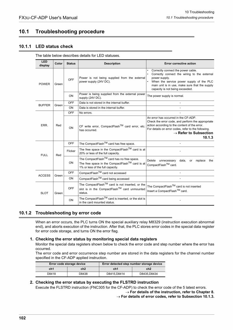
10 Troubleshooting
10.1 Troubleshooting procedureFX3U-CF-ADP User's Manual
10.1 Troubleshooting procedure
10.1.1 LED status check
The table below describes details for LED statuses.
10.1.2 Troubleshooting by error code
When an error occurs, the PLC turns ON the special auxiliary relay M8329 (instruction execution abnormalend), and aborts execution of the instruction. After that, the PLC stores error codes in the special data registerfor error code storage, and turns ON the error flag.
1. Checking the error status by monitoring special data registersMonitor the special data registers shown below to check the error code and step number where the error hasoccurred.The error code and error occurrence step number are stored in the data registers for the channel numberspecified in the CF-ADP applied instruction.
2. Checking the error status by executing the FLSTRD instructionExecute the FLSTRD instruction (FNC305 for the CF-ADP) to check the error code of the 5 latest errors.
For details of the instruction, refer to Chapter 8.For details of error codes, refer to Subsection 10.1.3.
LED display
Color Status Description Error corrective action
POWER Green
OFFPower is not being supplied from the externalpower supply (24V DC).
• Correctly connect the power cable.• Correctly connect the wiring to the external
power supply.• When the service power supply of the PLC
main unit is in use, make sure that the supplycapacity is not being exceeded.
ONPower is being supplied from the external powersupply (24V DC).
The power supply is normal.
BUFFER GreenOFF Data is not stored in the internal buffer. -
ON Data is stored in the internal buffer. -
ERR. Red
OFF No errors. -
ON CF write error, CompactFlashTM card error, etc.has occurred.
An error has occurred in the CF-ADP.Check the error code, and perform the appropriateaction according to the content of the error.For details on error codes, refer to the following.
Refer to Subsection10.1.3
FULL Red
OFF The CompactFlashTM card has free space. -
Flicker The free space in the CompactFlashTM card is at20% or less of the full capacity.
-
ONThe CompactFlashTM card has no free space.
The free space in the CompactFlashTM card is at1% or less of the full capacity.
Delete unnecessary data, or replace the
CompactFlashTM card.
ACCESS GreenOFF CompactFlashTM card not accessed -
ON CompactFlashTM card being accessed -
SLOT Green
OFFThe CompactFlashTM card is not inserted, or the
slot is in the CompactFlashTM card unmountedstatus.
The CompactFlashTM card is not inserted
Insert a CompactFlashTM card.
ON The CompactFlashTM card is inserted, or the slot isin the card mounted status.
-
Error code storage device Error detected step number storage device
ch1 ch2 ch1 ch2
D8418 D8438 D8415,D8414 D8435,D8434
102
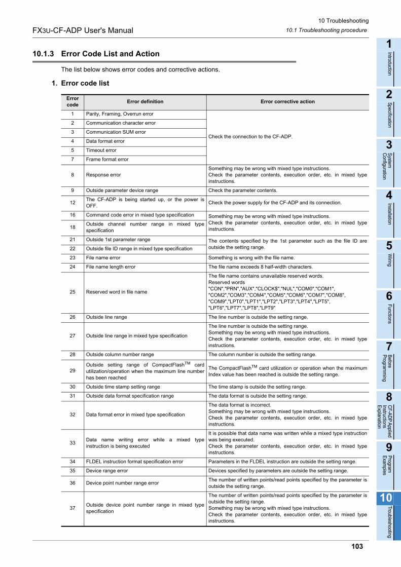
10 Troubleshooting
10.1 Troubleshooting procedureFX3U-CF-ADP User's Manual
1
Introduction
2
Specification
3
System
C
onfiguration
4
Installation
5
Wiring
6
Functions
7
Before
Program
ming
8
CF-A
DP
Applied
Instructions E
xplanation
9
Program
E
xamples
10
Troubleshooting
10.1.3 Error Code List and Action
The list below shows error codes and corrective actions.
1. Error code list
Error code
Error definition Error corrective action
1 Parity, Framing, Overrun error
Check the connection to the CF-ADP.
2 Communication character error
3 Communication SUM error
4 Data format error
5 Timeout error
7 Frame format error
8 Response errorSomething may be wrong with mixed type instructions.Check the parameter contents, execution order, etc. in mixed typeinstructions.
9 Outside parameter device range Check the parameter contents.
12The CF-ADP is being started up, or the power isOFF.
Check the power supply for the CF-ADP and its connection.
16 Command code error in mixed type specification Something may be wrong with mixed type instructions.Check the parameter contents, execution order, etc. in mixed typeinstructions.18
Outside channel number range in mixed typespecification
21 Outside 1st parameter range The contents specified by the 1st parameter such as the file ID areoutside the setting range.22 Outside file ID range in mixed type specification
23 File name error Something is wrong with the file name.
24 File name length error The file name exceeds 8 half-width characters.
25 Reserved word in file name
The file name contains unavailable reserved words.Reserved words"CON","PRN","AUX","CLOCK$","NUL","COM0","COM1","COM2","COM3","COM4","COM5","COM6","COM7","COM8","COM9","LPT0","LPT1","LPT2","LPT3","LPT4","LPT5","LPT6","LPT7","LPT8","LPT9"
26 Outside line range The line number is outside the setting range.
27 Outside line range in mixed type specification
The line number is outside the setting range.Something may be wrong with mixed type instructions.Check the parameter contents, execution order, etc. in mixed typeinstructions.
28 Outside column number range The column number is outside the setting range.
29Outside setting range of CompactFlashTM cardutilization/operation when the maximum line numberhas been reached
The CompactFlashTM card utilization or operation when the maximumIndex value has been reached is outside the setting range.
30 Outside time stamp setting range The time stamp is outside the setting range.
31 Outside data format specification range The data format is outside the setting range.
32 Data format error in mixed type specification
The data format is incorrect.Something may be wrong with mixed type instructions.Check the parameter contents, execution order, etc. in mixed typeinstructions.
33Data name writing error while a mixed typeinstruction is being executed
It is possible that data name was written while a mixed type instructionwas being executed.Check the parameter contents, execution order, etc. in mixed typeinstructions.
34 FLDEL instruction format specification error Parameters in the FLDEL instruction are outside the setting range.
35 Device range error Devices specified by parameters are outside the setting range.
36 Device point number range errorThe number of written points/read points specified by the parameter isoutside the setting range.
37Outside device point number range in mixed typespecification
The number of written points/read points specified by the parameter isoutside the setting range.Something may be wrong with mixed type instructions.Check the parameter contents, execution order, etc. in mixed typeinstructions.
103

10 Troubleshooting
10.1 Troubleshooting procedureFX3U-CF-ADP User's Manual
38 Mixed type instruction execution error The number of written/read points specified by the parameter is outsidethe setting range.Check the parameter contents, execution order, etc. in mixed typeinstructions.
42 Response device type error
43 Frame number error
46 Too many charactersThe character string exceeds 512 full-width characters, or the dataname exceeds 32 full-width characters.
200 System errorSomething may be wrong with the hardware.Contact your local Mitsubishi Electric representative.
201 Power shutdown history reading errorCheck whether a CompactFlashTM card having sufficient free space is
mounted correctly. When a CompactFlashTM card is mounted correctly,something may be wrong with the hardware.Contact your local Mitsubishi Electric representative.
202 Power shutdown history writing error
203 Power shutdown history corruption
204 Power shutdown history backup error
205 System errorSomething may be wrong with the hardware.Contact your local Mitsubishi Electric representative.
206 Power shutdown detectionShutdown of the supply voltage is detected.Check whether the power is supplied correctly.
300 SDRAM error
Something may be wrong with the hardware.Contact your local Mitsubishi Electric representative.
301 ROM error
302 EPROM error
303 SRAM error
304 SUM check error
400 CompactFlashTM card unmounted error
The CompactFlashTM card is not mounted in the CompactFlashTM cardslot.
Mount the CompactFlashTM card correctly in the CompactFlashTM cardslot.
401 CompactFlashTM card errorThe CompactFlashTM card may be defective.
Replace the CompactFlashTM card with another one.
402 CompactFlashTM card mount errorThe CompactFlashTM card is not formatted correctly.
Format the CompactFlashTM card, or replace it with another one.
404 CF free space acquisition errorThe CompactFlashTM card may be defective.
Format the CompactFlashTM card, or replace it with another one.
405 CF FULLThe CompactFlashTM card is full.
Delete unnecessary data, or replace the CompactFlashTM card withanother one.
406 Directory creation error
A folder was not able to be created in the CompactFlashTM card.Check whether the number of files and folders in the root directory in
the CompactFlashTM card does not exceed 512.
Check whether the CompactFlashTM card is formatted, and whether itis ready for data writing.
407 CompactFlashTM card format error
The CompactFlashTM card is not formatted correctly.
Check whether the CompactFlashTM card is mounted correctly.
Format the CompactFlashTM card, or replace it with another one.
500 Line file errorAccess to the file management information file has failed.
Check whether the CompactFlashTM card is mounted correctly.
501 ID table open error
The file management information was not able to be read from the
CompactFlashTM card.When reading or deleting a file, confirm that the target file exists.
502 ID table write error
The file management information was not able to be created in the
CompactFlashTM card.
Check whether the CompactFlashTM card is ready for data writing.
503 ID table read error
The file management information was not able to be read from the
CompactFlashTM card.When reading or deleting a file, confirm that the target file exists.
504 ID table corruption error The file management information is corrupt.
505 ID table not foundThe file management information does not exist in the
CompactFlashTM card.
Error code
Error definition Error corrective action
104
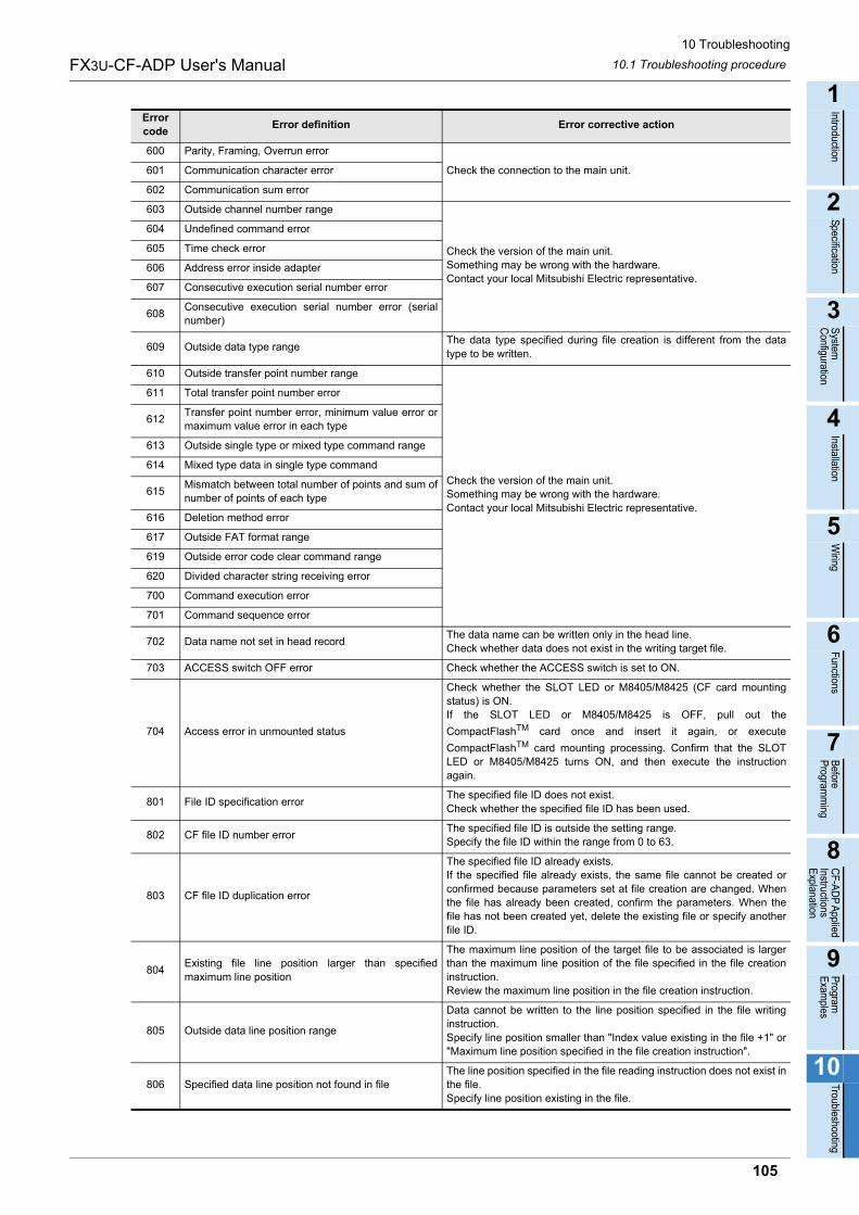
10 Troubleshooting
10.1 Troubleshooting procedureFX3U-CF-ADP User's Manual
1
Introduction
2
Specification
3
System
C
onfiguration
4
Installation
5
Wiring
6
Functions
7
Before
Program
ming
8
CF-A
DP
Applied
Instructions E
xplanation
9
Program
E
xamples
10
Troubleshooting
600 Parity, Framing, Overrun error
Check the connection to the main unit.601 Communication character error
602 Communication sum error
603 Outside channel number range
Check the version of the main unit.Something may be wrong with the hardware.Contact your local Mitsubishi Electric representative.
604 Undefined command error
605 Time check error
606 Address error inside adapter
607 Consecutive execution serial number error
608Consecutive execution serial number error (serialnumber)
609 Outside data type rangeThe data type specified during file creation is different from the datatype to be written.
610 Outside transfer point number range
Check the version of the main unit.Something may be wrong with the hardware.Contact your local Mitsubishi Electric representative.
611 Total transfer point number error
612Transfer point number error, minimum value error ormaximum value error in each type
613 Outside single type or mixed type command range
614 Mixed type data in single type command
615Mismatch between total number of points and sum ofnumber of points of each type
616 Deletion method error
617 Outside FAT format range
619 Outside error code clear command range
620 Divided character string receiving error
700 Command execution error
701 Command sequence error
702 Data name not set in head recordThe data name can be written only in the head line.Check whether data does not exist in the writing target file.
703 ACCESS switch OFF error Check whether the ACCESS switch is set to ON.
704 Access error in unmounted status
Check whether the SLOT LED or M8405/M8425 (CF card mountingstatus) is ON.If the SLOT LED or M8405/M8425 is OFF, pull out the
CompactFlashTM card once and insert it again, or execute
CompactFlashTM card mounting processing. Confirm that the SLOTLED or M8405/M8425 turns ON, and then execute the instructionagain.
801 File ID specification errorThe specified file ID does not exist.Check whether the specified file ID has been used.
802 CF file ID number errorThe specified file ID is outside the setting range.Specify the file ID within the range from 0 to 63.
803 CF file ID duplication error
The specified file ID already exists.If the specified file already exists, the same file cannot be created orconfirmed because parameters set at file creation are changed. Whenthe file has already been created, confirm the parameters. When thefile has not been created yet, delete the existing file or specify anotherfile ID.
804Existing file line position larger than specifiedmaximum line position
The maximum line position of the target file to be associated is largerthan the maximum line position of the file specified in the file creationinstruction.Review the maximum line position in the file creation instruction.
805 Outside data line position range
Data cannot be written to the line position specified in the file writinginstruction.Specify line position smaller than "Index value existing in the file +1" or"Maximum line position specified in the file creation instruction".
806 Specified data line position not found in fileThe line position specified in the file reading instruction does not exist inthe file.Specify line position existing in the file.
Error code
Error definition Error corrective action
105
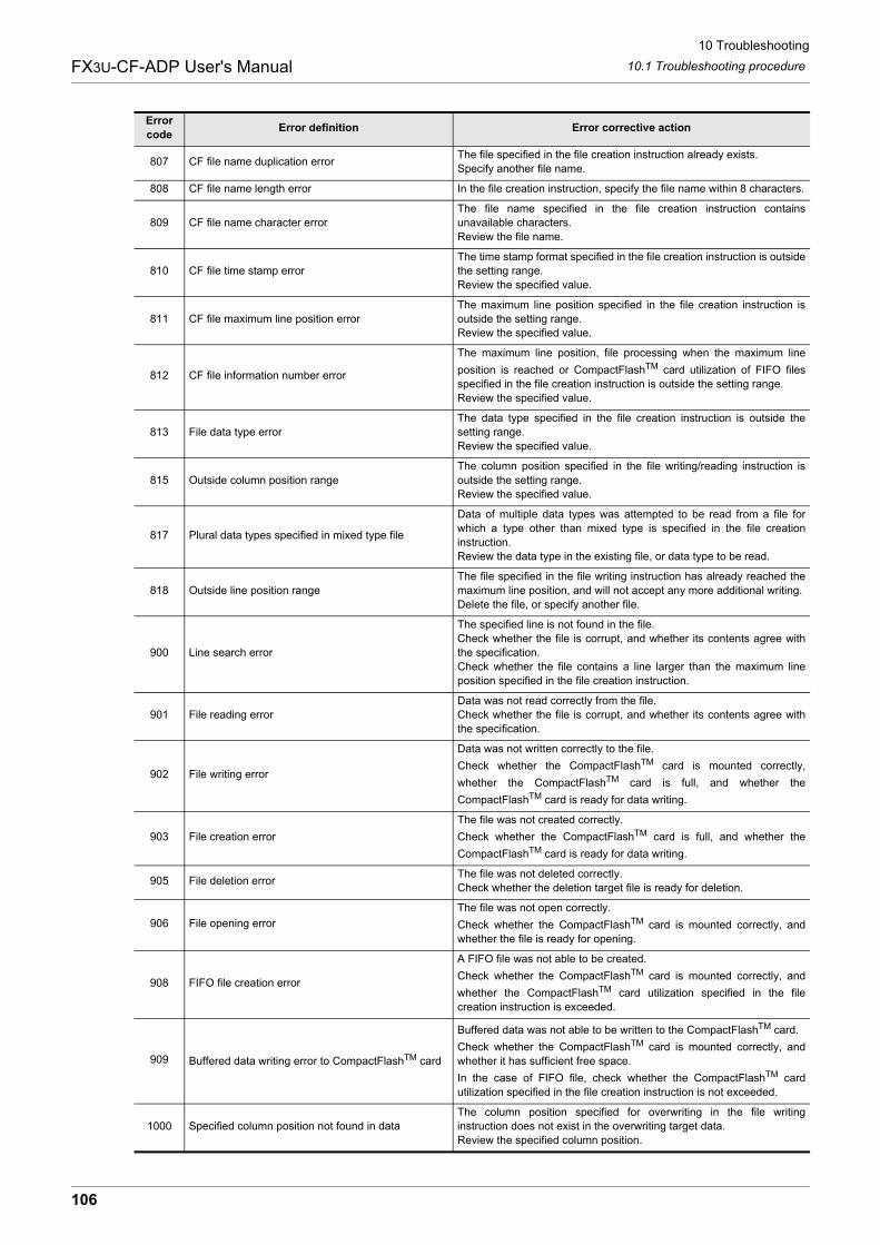
10 Troubleshooting
10.1 Troubleshooting procedureFX3U-CF-ADP User's Manual
807 CF file name duplication errorThe file specified in the file creation instruction already exists.Specify another file name.
808 CF file name length error In the file creation instruction, specify the file name within 8 characters.
809 CF file name character errorThe file name specified in the file creation instruction containsunavailable characters.Review the file name.
810 CF file time stamp errorThe time stamp format specified in the file creation instruction is outsidethe setting range.Review the specified value.
811 CF file maximum line position errorThe maximum line position specified in the file creation instruction isoutside the setting range.Review the specified value.
812 CF file information number error
The maximum line position, file processing when the maximum line
position is reached or CompactFlashTM card utilization of FIFO filesspecified in the file creation instruction is outside the setting range.Review the specified value.
813 File data type errorThe data type specified in the file creation instruction is outside thesetting range.Review the specified value.
815 Outside column position rangeThe column position specified in the file writing/reading instruction isoutside the setting range.Review the specified value.
817 Plural data types specified in mixed type file
Data of multiple data types was attempted to be read from a file forwhich a type other than mixed type is specified in the file creationinstruction.Review the data type in the existing file, or data type to be read.
818 Outside line position rangeThe file specified in the file writing instruction has already reached themaximum line position, and will not accept any more additional writing.Delete the file, or specify another file.
900 Line search error
The specified line is not found in the file.Check whether the file is corrupt, and whether its contents agree withthe specification.Check whether the file contains a line larger than the maximum lineposition specified in the file creation instruction.
901 File reading errorData was not read correctly from the file.Check whether the file is corrupt, and whether its contents agree withthe specification.
902 File writing error
Data was not written correctly to the file.
Check whether the CompactFlashTM card is mounted correctly,
whether the CompactFlashTM card is full, and whether the
CompactFlashTM card is ready for data writing.
903 File creation error
The file was not created correctly.
Check whether the CompactFlashTM card is full, and whether the
CompactFlashTM card is ready for data writing.
905 File deletion errorThe file was not deleted correctly.Check whether the deletion target file is ready for deletion.
906 File opening error
The file was not open correctly.
Check whether the CompactFlashTM card is mounted correctly, andwhether the file is ready for opening.
908 FIFO file creation error
A FIFO file was not able to be created.
Check whether the CompactFlashTM card is mounted correctly, and
whether the CompactFlashTM card utilization specified in the filecreation instruction is exceeded.
909 Buffered data writing error to CompactFlashTM card
Buffered data was not able to be written to the CompactFlashTM card.
Check whether the CompactFlashTM card is mounted correctly, andwhether it has sufficient free space.
In the case of FIFO file, check whether the CompactFlashTM cardutilization specified in the file creation instruction is not exceeded.
1000 Specified column position not found in dataThe column position specified for overwriting in the file writinginstruction does not exist in the overwriting target data.Review the specified column position.
Error code
Error definition Error corrective action
106
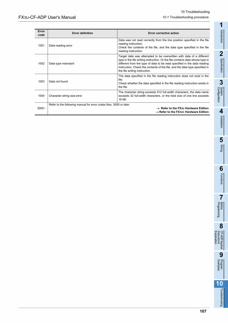
10 Troubleshooting
10.1 Troubleshooting procedureFX3U-CF-ADP User's Manual
1
Introduction
2
Specification
3
System
C
onfiguration
4
Installation
5
Wiring
6
Functions
7
Before
Program
ming
8
CF-A
DP
Applied
Instructions E
xplanation
9
Program
E
xamples
10
Troubleshooting
1001 Data reading error
Data was not read correctly from the line position specified in the filereading instruction.Check the contents of the file, and the data type specified in the filereading instruction.
1002 Data type mismatch
Target data was attempted to be overwritten with data of a differenttype in the file writing instruction. Or the file contains data whose type isdifferent from the type of data to be read specified in the data readinginstruction. Check the contents of the file, and the data type specified inthe file writing instruction.
1003 Data not found
The data specified in the file reading instruction does not exist in thefile.Check whether the data specified in the file reading instruction exists inthe file.
1004 Character string size errorThe character string exceeds 512 full-width characters, the data nameexceeds 32 full-width characters, or the total size of one line exceeds16 kB.
3000~Refer to the following manual for error codes Nos. 3000 or later.
Refer to the FX3U Hardware EditionRefer to the FX3UC Hardware Edition
Error code
Error definition Error corrective action
107
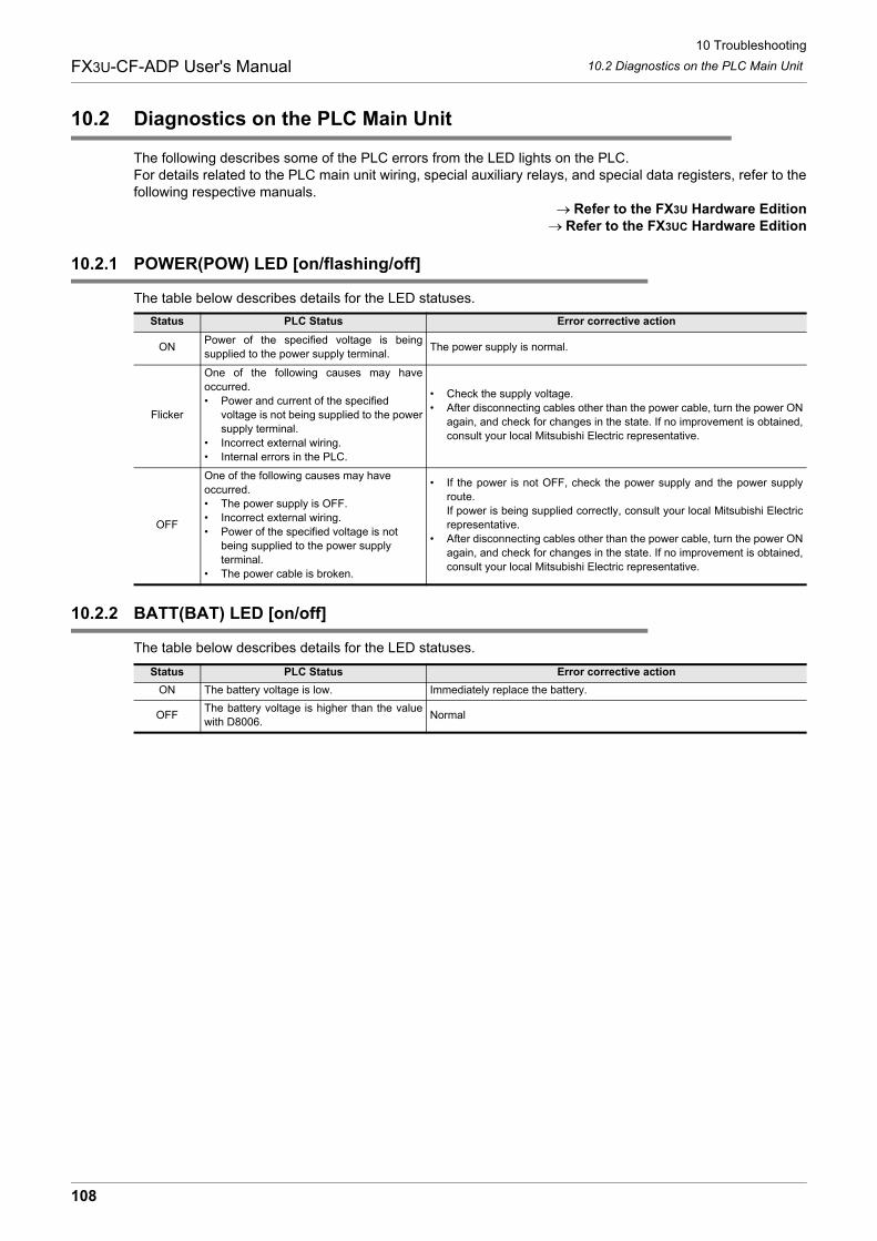
10 Troubleshooting
10.2 Diagnostics on the PLC Main UnitFX3U-CF-ADP User's Manual
10.2 Diagnostics on the PLC Main Unit
The following describes some of the PLC errors from the LED lights on the PLC.For details related to the PLC main unit wiring, special auxiliary relays, and special data registers, refer to thefollowing respective manuals.
Refer to the FX3U Hardware EditionRefer to the FX3UC Hardware Edition
10.2.1 POWER(POW) LED [on/flashing/off]
The table below describes details for the LED statuses.
10.2.2 BATT(BAT) LED [on/off]
The table below describes details for the LED statuses.
Status PLC Status Error corrective action
ONPower of the specified voltage is beingsupplied to the power supply terminal.
The power supply is normal.
Flicker
One of the following causes may haveoccurred.• Power and current of the specified
voltage is not being supplied to the powersupply terminal.
• Incorrect external wiring.• Internal errors in the PLC.
• Check the supply voltage.• After disconnecting cables other than the power cable, turn the power ON
again, and check for changes in the state. If no improvement is obtained,consult your local Mitsubishi Electric representative.
OFF
One of the following causes may have occurred.• The power supply is OFF.• Incorrect external wiring.• Power of the specified voltage is not
being supplied to the power supply terminal.
• The power cable is broken.
• If the power is not OFF, check the power supply and the power supplyroute.If power is being supplied correctly, consult your local Mitsubishi Electricrepresentative.
• After disconnecting cables other than the power cable, turn the power ONagain, and check for changes in the state. If no improvement is obtained,consult your local Mitsubishi Electric representative.
Status PLC Status Error corrective action
ON The battery voltage is low. Immediately replace the battery.
OFFThe battery voltage is higher than the valuewith D8006.
Normal
108
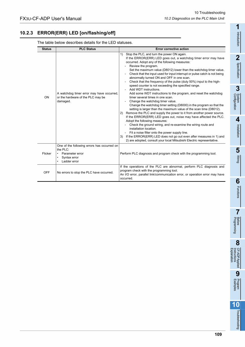
10 Troubleshooting
10.2 Diagnostics on the PLC Main UnitFX3U-CF-ADP User's Manual
1
Introduction
2
Specification
3
System
C
onfiguration
4
Installation
5
Wiring
6
Functions
7
Before
Program
ming
8
CF-A
DP
Applied
Instructions E
xplanation
9
Program
E
xamples
10
Troubleshooting
10.2.3 ERROR(ERR) LED [on/flashing/off]
The table below describes details for the LED statuses.
Status PLC Status Error corrective action
ONA watchdog timer error may have occurred,or the hardware of the PLC may be damaged.
1) Stop the PLC, and turn the power ON again.If the ERROR(ERR) LED goes out, a watchdog timer error may haveoccurred. Adopt any of the following measures:
- Review the program.Set the maximum value (D8012) lower than the watchdog timer value.
- Check that the input used for input interrupt or pulse catch is not being abnormally turned ON and OFF in one scan.
- Check that the frequency of the pulse (duty 50%) input to the high-speed counter is not exceeding the specified range.
- Add WDT instructions.Add some WDT instructions to the program, and reset the watchdog timer several times in one scan.
- Change the watchdog timer value.Change the watchdog timer setting (D8000) in the program so that the setting is larger than the maximum value of the scan time (D8012).
2) Remove the PLC and supply the power to it from another power source.If the ERROR(ERR) LED goes out, noise may have affected the PLC.Adopt the following measures:
- Check the ground wiring, and re-examine the wiring route and installation location.
- Fit a noise filter onto the power supply line.3) If the ERROR(ERR) LED does not go out even after measures in 1) and
2) are adopted, consult your local Mitsubishi Electric representative.
Flicker
One of the following errors has occurred onthe PLC:• Parameter error• Syntax error• Ladder error
Perform PLC diagnosis and program check with the programming tool.
OFF No errors to stop the PLC have occurred.
If the operations of the PLC are abnormal, perform PLC diagnosis andprogram check with the programming tool.An I/O error, parallel link/communication error, or operation error may haveoccurred.
109
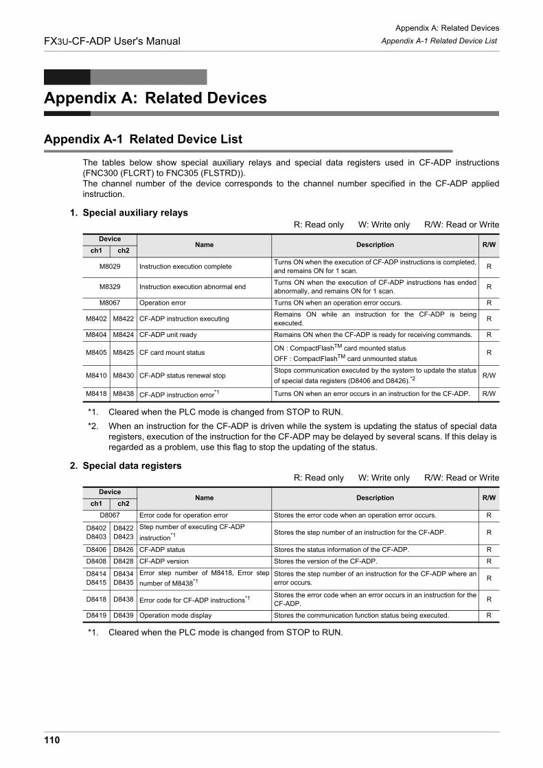
Appendix A: Related Devices
Appendix A-1 Related Device ListFX3U-CF-ADP User's Manual
Appendix A: Related Devices
Appendix A-1 Related Device List
The tables below show special auxiliary relays and special data registers used in CF-ADP instructions(FNC300 (FLCRT) to FNC305 (FLSTRD)).The channel number of the device corresponds to the channel number specified in the CF-ADP appliedinstruction.
1. Special auxiliary relaysR: Read only W: Write only R/W: Read or Write
*1. Cleared when the PLC mode is changed from STOP to RUN.
*2. When an instruction for the CF-ADP is driven while the system is updating the status of special dataregisters, execution of the instruction for the CF-ADP may be delayed by several scans. If this delay isregarded as a problem, use this flag to stop the updating of the status.
2. Special data registersR: Read only W: Write only R/W: Read or Write
*1. Cleared when the PLC mode is changed from STOP to RUN.
DeviceName Description R/W
ch1 ch2
M8029 Instruction execution completeTurns ON when the execution of CF-ADP instructions is completed,and remains ON for 1 scan.
R
M8329 Instruction execution abnormal endTurns ON when the execution of CF-ADP instructions has endedabnormally, and remains ON for 1 scan.
R
M8067 Operation error Turns ON when an operation error occurs. R
M8402 M8422 CF-ADP instruction executingRemains ON while an instruction for the CF-ADP is beingexecuted.
R
M8404 M8424 CF-ADP unit ready Remains ON when the CF-ADP is ready for receiving commands. R
M8405 M8425 CF card mount statusON : CompactFlashTM card mounted status
OFF : CompactFlashTM card unmounted statusR
M8410 M8430 CF-ADP status renewal stopStops communication executed by the system to update the status
of special data registers (D8406 and D8426).*2R/W
M8418 M8438 CF-ADP instruction error*1 Turns ON when an error occurs in an instruction for the CF-ADP. R/W
DeviceName Description R/W
ch1 ch2
D8067 Error code for operation error Stores the error code when an operation error occurs. R
D8402D8403
D8422D8423
Step number of executing CF-ADP
instruction*1 Stores the step number of an instruction for the CF-ADP. R
D8406 D8426 CF-ADP status Stores the status information of the CF-ADP. R
D8408 D8428 CF-ADP version Stores the version of the CF-ADP. R
D8414D8415
D8434D8435
Error step number of M8418, Error step
number of M8438*1Stores the step number of an instruction for the CF-ADP where anerror occurs.
R
D8418 D8438 Error code for CF-ADP instructions*1 Stores the error code when an error occurs in an instruction for theCF-ADP.
R
D8419 D8439 Operation mode display Stores the communication function status being executed. R
110
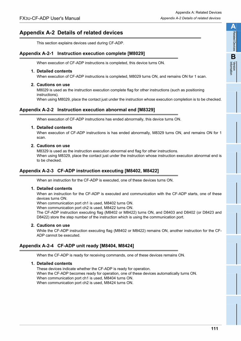
Appendix A: Related Devices
Appendix A-2 Details of related devicesFX3U-CF-ADP User's Manual
A
Related D
evices
B
Version Inform
ation
Appendix A-2 Details of related devices
This section explains devices used during CF-ADP.
Appendix A-2-1 Instruction execution complete [M8029]
When execution of CF-ADP instructions is completed, this device turns ON.
1. Detailed contentsWhen execution of CF-ADP instructions is completed, M8029 turns ON, and remains ON for 1 scan.
2. Cautions on useM8029 is used as the instruction execution complete flag for other instructions (such as positioning instructions). When using M8029, place the contact just under the instruction whose execution completion is to be checked.
Appendix A-2-2 Instruction execution abnormal end [M8329]
When execution of CF-ADP instructions has ended abnormally, this device turns ON.
1. Detailed contentsWhen execution of CF-ADP instructions is has ended abnormally, M8329 turns ON, and remains ON for 1scan.
2. Cautions on useM8329 is used as the instruction execution abnormal end flag for other instructions.When using M8329, place the contact just under the instruction whose instruction execution abnormal end isto be checked.
Appendix A-2-3 CF-ADP instruction executing [M8402, M8422]
When an instruction for the CF-ADP is executed, one of these devices turns ON.
1. Detailed contentsWhen an instruction for the CF-ADP is executed and communication with the CF-ADP starts, one of thesedevices turns ON.When communication port ch1 is used, M8402 turns ON.When communication port ch2 is used, M8422 turns ON.The CF-ADP instruction executing flag (M8402 or M8422) turns ON, and D8403 and D8402 (or D8423 andD8422) store the step number of the instruction which is using the communication port.
2. Cautions on useWhile the CF-ADP instruction executing flag (M8402 or M8422) remains ON, another instruction for the CF-ADP cannot be executed.
Appendix A-2-4 CF-ADP unit ready [M8404, M8424]
When the CF-ADP is ready for receiving commands, one of these devices remains ON.
1. Detailed contentsThese devices indicate whether the CF-ADP is ready for operation.When the CF-ADP becomes ready for operation, one of these devices automatically turns ON.When communication port ch1 is used, M8404 turns ON.When communication port ch2 is used, M8424 turns ON.
111
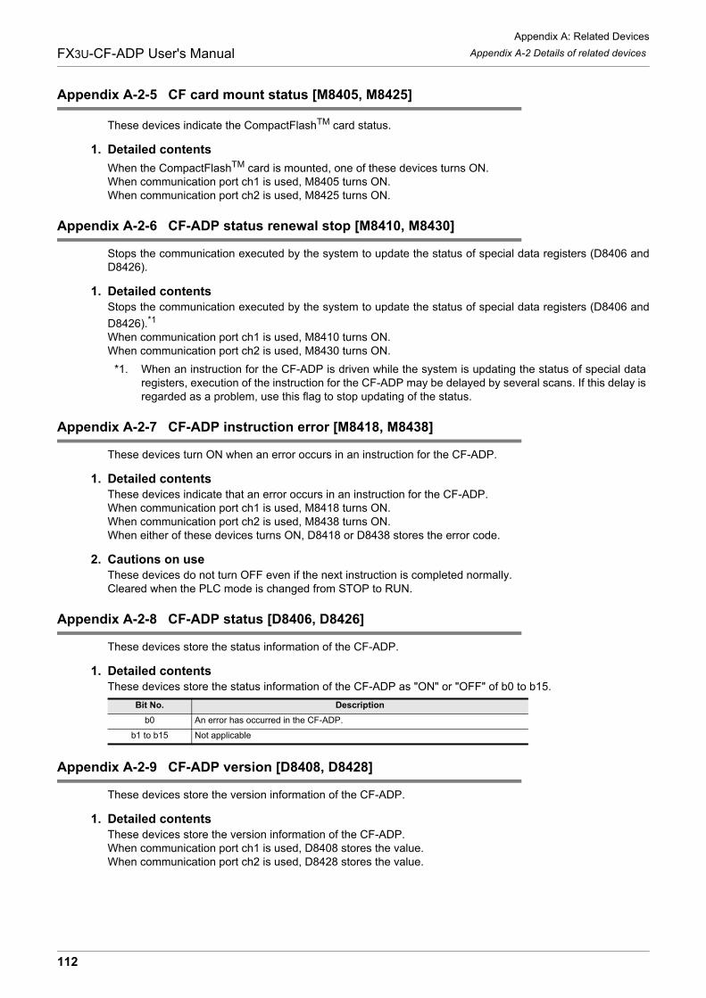
Appendix A: Related Devices
Appendix A-2 Details of related devicesFX3U-CF-ADP User's Manual
Appendix A-2-5 CF card mount status [M8405, M8425]
These devices indicate the CompactFlashTM card status.
1. Detailed contents
When the CompactFlashTM card is mounted, one of these devices turns ON.When communication port ch1 is used, M8405 turns ON.When communication port ch2 is used, M8425 turns ON.
Appendix A-2-6 CF-ADP status renewal stop [M8410, M8430]
Stops the communication executed by the system to update the status of special data registers (D8406 andD8426).
1. Detailed contentsStops the communication executed by the system to update the status of special data registers (D8406 and
D8426).*1
When communication port ch1 is used, M8410 turns ON.When communication port ch2 is used, M8430 turns ON.
*1. When an instruction for the CF-ADP is driven while the system is updating the status of special dataregisters, execution of the instruction for the CF-ADP may be delayed by several scans. If this delay isregarded as a problem, use this flag to stop updating of the status.
Appendix A-2-7 CF-ADP instruction error [M8418, M8438]
These devices turn ON when an error occurs in an instruction for the CF-ADP.
1. Detailed contentsThese devices indicate that an error occurs in an instruction for the CF-ADP.When communication port ch1 is used, M8418 turns ON.When communication port ch2 is used, M8438 turns ON.When either of these devices turns ON, D8418 or D8438 stores the error code.
2. Cautions on useThese devices do not turn OFF even if the next instruction is completed normally.Cleared when the PLC mode is changed from STOP to RUN.
Appendix A-2-8 CF-ADP status [D8406, D8426]
These devices store the status information of the CF-ADP.
1. Detailed contentsThese devices store the status information of the CF-ADP as "ON" or "OFF" of b0 to b15.
Appendix A-2-9 CF-ADP version [D8408, D8428]
These devices store the version information of the CF-ADP.
1. Detailed contentsThese devices store the version information of the CF-ADP.When communication port ch1 is used, D8408 stores the value.When communication port ch2 is used, D8428 stores the value.
Bit No. Description
b0 An error has occurred in the CF-ADP.
b1 to b15 Not applicable
112
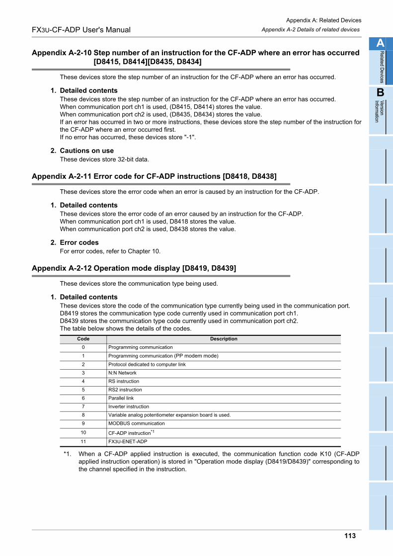
Appendix A: Related Devices
Appendix A-2 Details of related devicesFX3U-CF-ADP User's Manual
A
Related D
evices
B
Version Inform
ation
Appendix A-2-10 Step number of an instruction for the CF-ADP where an error has occurred [D8415, D8414][D8435, D8434]
These devices store the step number of an instruction for the CF-ADP where an error has occurred.
1. Detailed contentsThese devices store the step number of an instruction for the CF-ADP where an error has occurred.When communication port ch1 is used, (D8415, D8414) stores the value.When communication port ch2 is used, (D8435, D8434) stores the value.If an error has occurred in two or more instructions, these devices store the step number of the instruction forthe CF-ADP where an error occurred first.If no error has occurred, these devices store "-1".
2. Cautions on useThese devices store 32-bit data.
Appendix A-2-11 Error code for CF-ADP instructions [D8418, D8438]
These devices store the error code when an error is caused by an instruction for the CF-ADP.
1. Detailed contentsThese devices store the error code of an error caused by an instruction for the CF-ADP.When communication port ch1 is used, D8418 stores the value.When communication port ch2 is used, D8438 stores the value.
2. Error codesFor error codes, refer to Chapter 10.
Appendix A-2-12 Operation mode display [D8419, D8439]
These devices store the communication type being used.
1. Detailed contentsThese devices store the code of the communication type currently being used in the communication port.D8419 stores the communication type code currently used in communication port ch1.D8439 stores the communication type code currently used in communication port ch2.The table below shows the details of the codes.
*1. When a CF-ADP applied instruction is executed, the communication function code K10 (CF-ADPapplied instruction operation) is stored in "Operation mode display (D8419/D8439)" corresponding tothe channel specified in the instruction.
Code Description
0 Programming communication
1 Programming communication (PP modem mode)
2 Protocol dedicated to computer link
3 N:N Network
4 RS instruction
5 RS2 instruction
6 Parallel link
7 Inverter instruction
8 Variable analog potentiometer expansion board is used.
9 MODBUS communication
10 CF-ADP instruction*1
11 FX3U-ENET-ADP
113

Appendix A: Related Devices
Appendix A-2 Details of related devicesFX3U-CF-ADP User's Manual
MEMO
114
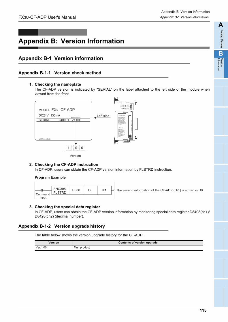
Appendix B: Version Information
Appendix B-1 Version informationFX3U-CF-ADP User's Manual
A
Related D
evices
B
Version Inform
ation
Appendix B: Version Information
Appendix B-1 Version information
Appendix B-1-1 Version check method
1. Checking the nameplateThe CF-ADP version is indicated by "SERIAL" on the label attached to the left side of the module whenviewed from the front.
2. Checking the CF-ADP instructionIn CF-ADP, users can obtain the CF-ADP version information by FLSTRD instruction.
Program Example
3. Checking the special data registerIn CF-ADP, users can obtain the CF-ADP version information by monitoring special data register D8408(ch1)/D8428(ch2) (decimal number).
Appendix B-1-2 Version upgrade history
The table below shows the version upgrade history for the CF-ADP.
Version Contents of version upgrade
Ver.1.00 First product
MODEL
DC24V 130mASERIAL
FX3U-CF-ADP
940001 V1.00
1 . 0
Version
0
MADE IN JAPAN
Left side
The version information of the CF-ADP (ch1) is stored in D0.K1H300 FNC305 FLSTRDCommand
input
D0
115

Appendix B: Version Information
Appendix B-1 Version informationFX3U-CF-ADP User's Manual
MEMO
116
FX3U-CF-ADP User's Manual Warranty
Warranty
Please confirm the following product warranty details before using this product.1. Gratis Warranty Term and Gratis Warranty Range
[Gratis Warranty Term]
If any faults or defects (hereinafter "Failure") found to be the responsibility of Mitsubishi occurs during use of the product within the gratis warranty term, the product shall be repaired at no cost via the sales representative or Mitsubishi Service Company. However, if repairs are required onsite at domestic or overseas location, expenses to send an engineer will be solely at the customer's discretion. Mitsubishi shall not be held responsible for any re-commissioning, maintenance, or testing on-site that involves replacement of the failed module.
Overseas, repairs shall be accepted by Mitsubishi's local overseas FA Center. Note that the repair conditions at each FA Center may differ. The gratis warranty term of the product shall be for one
year after the date of purchase or delivery to a designated place. Note that after manufacture and shipment from Mitsubishi, the maximum distribution period shall be six (6) months, and the longest gratis warranty term after manufacturing shall be eighteen (18) months. The gratis warranty term of repair parts shall not exceed the gratis warranty term before repairs. [Gratis Warranty Range]
The range shall be limited to normal use within the usage state, usage methods and usage environment, etc., which follow the conditions and precautions, etc., given in the instruction manual, user's manual and caution labels on the product.
1)
Even within the gratis warranty term, repairs shall be charged for in the following cases.
2)
Failure occurring from inappropriate storage or handling, carelessness or negligence by the user. Failure caused by the user's hardware or software design.
a)
Failure caused by unapproved modifications, etc., to the product by the user.
b)
Mitsubishi shall accept onerous product repairs for seven (7) years after production of the product is discontinued.Discontinuation of production shall be notified with Mitsubishi Technical Bulletins, etc.
1)
Product supply (including repair parts) is not available after production is discontinued.
2)
In using the Mitsubishi MELSEC programmable logic controller, the usage conditions shall be that the application will not lead to a major accident even if any problem or fault should occur in the programmable logic controller device, and that backup and fail-safe functions are systematically provided outside of the device for any problem or fault.
1)
The Mitsubishi programmable logic controller has been designed and manufactured for applications in general industries, etc. Thus, applications in which the public could be affected such as in nuclear power plants and other power plants operated by respective power companies, and applications in which a special quality assurance system is required, such as for Railway companies or Public service purposes shall be excluded from the programmable logic controller applications. In addition, applications in which human life or property that could be greatly affected, such as in aircraft, medical applications, incineration and fuel devices, manned transportation, equipment for recreation and amusement, and safety devices, shall also be excluded from the programmable logic controller range of applications. However, in certain cases, some applications may be possible, providing the user consults their local Mitsubishi representative outlining the special requirements of the project, and providing that all parties concerned agree to the special circumstances, solely at the users discretion.
2)
When the Mitsubishi product is assembled into a user's device, Failure that could have been avoided if functions or structures, judged as necessary in the legal safety measures the user's device is subject to or as necessary by industry standards, had been provided.
c)
Failure that could have been avoided if consumable parts (battery, backlight, fuse, etc.) designated in the instruction manual had been correctly serviced or replaced.
d)
Relay failure or output contact failure caused by usage beyond the specified Life of contact (cycles).
e)
Failure caused by external irresistible forces such as fires or abnormal voltages, and failure caused by force majeure such as earthquakes, lightning, wind and water damage.
f)
Failure caused by reasons unpredictable by scientific technology standards at time of shipment from Mitsubishi.
g)
Any other failure found not to be the responsibility of Mitsubishi or that admitted not to be so by the user.
h)
2. Onerous repair term after discontinuation of production
4. Exclusion of loss in opportunity and secondary loss from warranty liability
3. Overseas service
The specifications given in the catalogs, manuals or technical documents are subject to change without prior notice.
5. Changes in product specifications
6. Product application
Regardless of the gratis warranty term, Mitsubishi shall not be liable for compensation of damages caused by any cause found not to be the responsibility of Mitsubishi, loss in opportunity, lost profits incurred to the user or third person by Failures of Mitsubishi products, special damages and secondary damages whether foreseeable or not, compensation for accidents, and compensation for damages to products other than Mitsubishi products, replacement by the user, maintenance of on-site equipment, start-up test run and other tasks.
117
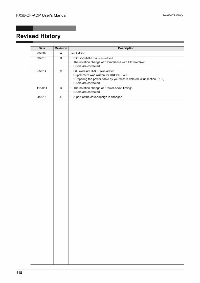
FX3U-CF-ADP User's Manual Revised History
Revised History
Date Revision Description
6/2009 A First Edition
9/2010 B • FX3UC-32MT-LT-2 was added.• The notation change of "Compliance with EC directive".• Errors are corrected.
5/2014 C • GX Works2/FX-30P was added.• Supplement was written for D8419/D8439.• "Preparing the power cable by yourself" is deleted. (Subsection 5.1.2)• Errors are corrected.
11/2014 D • The notation change of "Power-on/off timing".• Errors are corrected.
4/2015 E • A part of the cover design is changed.
118

HEAD OFFICE: TOKYO BUILDING, 2-7-3 MARUNOUCHI, CHIYODA-KU, TOKYO 100-8310, JAPAN
JY997D35401E(MEE)
Effective April 2015Specifications are subject to change without notice.
MODEL FX3U-CF-ADP-U-E
MODEL CODE 09R720
FX3U-CF-ADP
USER'S MANUAL