fy 2014/2015 qc category no. 1 statewide ... 2014/2015 qc category no. 1 statewide inspection...
TRANSCRIPT

FY 2014/2015 QC Category No. 1 STATEWIDE INSPECTION GUIDELIST
Clearing and Grubbing 1. Clearing and Grubbing limits are established according to contract documents. [Spec. 110-2] 2. Stumps and roots within roadway are removed and standard clearing and grubbing meets requirements shown in contract sections 110-2.1 through 110-2.4. Note, sections 110-2.1 to 110-2.4 are not shown in the 2000 Spec. Book as they were added after its publication. You must review your contract [Spec. 110-2] 3. Check location of selective clearing and grubbing areas designated in contract documents. Insure the Engineer’s instructions for both removal areas and retention areas for brush and trees have been carried out in the selective clearing and grubbing areas. [Spec. 110-3] 4. Burning of debris must be in accordance with applicable laws, ordinances, permits and regulations. {Spec. 110-9.2] 5. Existing structures, including foundations are removed to accommodate new construction. [Spec. 110-6.1 to 110-6.4] 6. Ensure that, except as specified otherwise in the contract documents, the Contractor takes ownership of, and disposes of all removed materials. [Spec. 110-9.1 to 110-9.5] 7. For miscellaneous operations such as plugging abandoned water wells, landscape areas, terrain leveling and mail box adjustment , ensure the Contractor meets the requirements specified. [Spec. 110-10] 8. Meet the requirements of Spec. 110-11 and 110-12 on method of measurement and basis of payment for clearing and grubbing. Monthly estimates should be made as stated in the Final Estimates Preparation and Documentation Manual (FEPDM). [FEPDM Chapter 3]

Maintenance of Traffic, GL–2, FY 2014/2015, Page 1 of 3
FY 2014/2015 QC Category No. 2 STATEWIDE INSPECTION GUIDELIST
Maintenance of Traffic (MOT)
1. The Contractor has submitted a letter stating whether the Contractor plans to use the Traffic Control Plan (TCP) provided in the contract or will submit an alternate TCP for approval. [CPAM 9.1.5]
2. If TCP provided in the contract is not being used, the Contractor provided an alternate
TCP signed and sealed by a Professional Engineer and approved by the Department before being used. [Specs. 102-4, CPAM 9.1.5]
3. The Contractor has provided the name and telephone number(s) of the Worksite
Traffic Supervisor (WTS) in writing. [Specs 5-8.3]
4. The WTS has provided a valid certificate of successfully completing an approved Advanced MOT training course. [Specs. 105-8.3]
5. The WTS is on site during all set up and take down, and performs a drive through
inspection immediately after set up. (Specs. 102-3.2)
6. The WTS does an initial inspection and evaluation of the work zone for each phase of construction and conducts daily daytime and weekly nighttime inspections within the limits of the project for projects with predominant daytime work activities and daily nighttime and weekly daytime inspections for projects with predominant nighttime work. The WTS notes any deficiencies in the MOT Review Report Form and provides a weekly report to the Project Administrator using form number 700-010-08. [Specs. 102-3, CPAM 9.1]
7. The Project Administrator has reviewed the Contractor’s weekly MOT Review Report
for reasonableness and accuracy by conducting a field project inspection of the work zone. [CPAM 9.1]
8. The WTS immediately corrects all safety deficiencies and does not allow minor
deficiencies that are not immediate safety hazards to remain uncorrected for more than 24 hours. [Specs. 102-3, CPAM 9.1]
9. The Project Administrator has completed the Engineer’s Maintenance of Traffic Evaluation at Crash Site, Form No. 700-010-64, for crashes occurring within the project limits. [CPAM 9.3]
10. The Contractor has provided access to all residences and businesses whenever
construction interferes with the existing means of access, and material has been placed, as needed, for driveways and sidewalks to residences and businesses to continuously provide safe, stable and reasonable access for vehicles and pedestrians. [Specs. 102-1, 102-5.5, 102-8, and Index 660]

Maintenance of Traffic, GL–2, FY 2014/2015, Page 2 of 3
11. For sidewalk closures, the Contractor has provided an alternate accessible path utilizing pedestrian longitudinal channelizing devices (LCDs) for pedestrian detours around the work area. Be sure this is noted by the WTS in the weekly MOT Review Report Forms. [Specs. 102-1, 102-3 and, Index 660]
12. The Contractor is controlling dust during construction operations. [Specs. 102-5.2]
13. The Contractor has removed all existing pavement markings in conflict with the
adjusted vehicle paths without damaging the surface texture and without the use of black paint. Cost for removing conflicting pavement markings is included in Maintenance of Traffic, Lump Sum. [Specs. 102-5.8, 2003 MUTCD 6F.71 and 2009 MUTCD 6F.77]
14. The Project Administrator has verified that the Contractor’s certified initial retroreflectivity readings meet the minimum requirements of 300 mcd/lx·m2 and 250 mcd/lx·m2 for white and yellow paint, respectively, and maintains 150 mcd/lx·m2 throughout the work zone. Refer to other sections of the specifications for different pavement marking products. [Specs. 102-10, 709-4, 709-7, 710-4, 711-4, 711-7, 713-4, 713-7, 971]
15. The Contractor has maintained Type A, C, and D warning lights so as to be capable of being visible on a clear night from a distance of 3000 feet, and Type B warning lights so as to be capable of being visible on a sunny day when viewed without the sun directly on or behind the device from a distance of 1000 feet. [2003 MUTCD Section 6F.78 and 2009 MUTCD Section 6F.83]
16. The Contractor has provided temporary traffic control devices that have been permanently marked with a valid QPL or APL number. [Specs. 102-9.1]
17. The Contractor has maintained temporary traffic control devices in accordance with
ATSSA’s Quality Guidelines for Temporary Traffic Control Devices and Features. [Specs. 102-9.1]
18. The Contractor has correctly installed work zone sign supports (post-mounted and
portable) that have been permanently marked with a valid QPL number. [Specs. 102-9.1,102-9.2, 700-2.5, 990-8, Index 600 Sheets 6 and 7]
19. The Contractor has placed business access signs as required by the contract. [Specs. 102-9.3, Index 600 Sheet 11]
20. The Project Administrator has verified that the crash cushions are installed in accordance with the plans, Design Standards, and QPL vendor drawings. [Specs. 102-9.6]
21. The Project Administrator has checked the contract before making payment, if any, for crash cushion repairs. [Specs. 102-13.12]

Maintenance of Traffic, GL–2, FY 2014/2015, Page 3 of 3
22. The Project Administrator has verified that the contractor is using a Traffic Control
Officer when using Design Standard 619 on freeway facilities (interstates, toll roads, and expressways) at nighttime. [Specs. 102-7]
23. The Project Administrator has verified that the temporary lane separator has been installed properly. [Specs. 102-9.17, Index 600]
24. Temporary signs on barrier or traffic railing are installed in accordance with Index 11871. [Index 11871]

GL–3, FY 2014/2015, Page 1 of 2
FY 2014/2015 QC Category No. 3 STATEWIDE GUIDE LIST
Environmental Compliance
1. **As soon as possible after getting a project assigned the CEI staff should review or have the district’s environmental specialist review the Contractor’s erosion control plan, to ensure it meets the requirements of NPDES, when an NPDES permit is required. [CPAM 8.2, Spec. 104-5]
2. **No construction activities can begin until the erosion control plan has been
approved by the engineer and governing regulatory agency, if needed. Where an NPDES permit is required, under no circumstances can any earth be disturbed until the prime Contractor(s) and any Subcontractor(s) that will install, maintain or monitor erosion control devices to implement the Storm Water Pollution Prevention Plan (SWPPP) sign the certification statement (Form No. 650-040-07). [CPAM 8.2, Spec. 104-5]
3. Confirm the Contractor has posted and is maintaining a copy of the notice of intent
in a prominent location on the construction site for public viewing. [CPAM 8.2.7] 4. Limit the area in which Clearing and Grubbing, and Excavation and Filling
operations, are being performed so that the capacity to prevent stormwater pollution is not exceeded. Do not expose more than 750,000 ft2 (70,000 m2) without specific approval. [Spec. 104-6]
5. The Project Administrator will monitor permit expiration dates for projects under
construction. The responsible Engineer will advise the District Permits Coordinator at least six months prior to an applicable permits expiration date if the permit will expire before the permitted activity is complete. [CPAM 8.2.6]
6. A copy of the Stormwater Pollution Prevention Plan (SWPPP) must be kept on the
construction site for the life of the project. [CPAM 8.2] 7. When an NPDES permit is required, make routine inspections every seven days or
within 24 hours of a 0.50 inch or greater rainfall, of all erosion prevention and sediment control devices installed on the project and document all deficiencies in the Daily Work Reports. Conduct inspections using qualified personnel who have successfully completed the Florida Department of Environmental Protection’s Florida Stromwater erosion and Sediment Control Inspector training. [CPAM 8.2.7, Spec. 7-2]
8. If deficiencies are noted in the Daily Work Report, make sure the Contractor begins
to correct them immediately. [CPAM 8.2.7, Spec. 104-6, 104-7]
9. If the Contractor fails to comply with any federal and state environmental regulations, including permit conditions, and does not promptly (within 24 hours) identify and correct all deficiencies on the project site, document all environmental noncompliance in the Contractor Past Performance Rating System.
10. Conduct construction operations in a manner that prevents soil erosion runoff or
siltation in any off site location. [Spec. 104-3] 11. The Contractor shall survey surface water management systems, bridge clearances,
and authorized work as directed by the permit conditions and contract documents and include the information on the as-built plans. [CPAM 8.2, Spec. 7-2]

GL–3, FY 2014/2015, Page 2 of 2
12. **CEI staff must notify the District Environmental Administrator and District Permits
Coordinator when the project is significantly complete. [CPAM 8.2] **These items only need to be verified once during the life of the project.
FY 2015/2016 QC Category No. 4 STATEWIDE INSPECTION GUIDELIST
Earthwork EXCAVATION / EMBANKMENT 1. If borrow pit is used, the location must be approved. [Spec. 120-6] 2. No work can be performed at an off-site construction activity area prior to obtaining clearance from the Division of Archives and complying with the Federal Endangered Species Act specified in Section 7-1.4. [Spec. 120-6] 3. Ensure that material used for embankment does not contain muck, stumps, roots, brush, vegetable matter, rubbish or other Material that does not compact into a suitable and enduring Roadbed. [Spec. 120-7] 4. Verify the maximum particle size does not exceed the specified limits. [Spec.120-7]. 5. Without thick lift approval, lift thickness for embankment soils that are not A-3 or A-2-4 with up to 15% fines must be 6 in. (150 mm) or less, compacted thickness, for the full embankment width. [Spec. 120-8] 6. Where thick lifts are demonstrated and approved, maximum lift thickness may not exceed 12 inches (300mm) compacted thickness. [Spec. 120-8] 7. Verify the Contractor compacts uniformly each layer, using equipment that will achieve the required density. [Spec. 120-9] 8. Ensure that initial equipment comparison is performed and valid calibrations are maintained for all equipment used on this project? 120-10.1.1 9. Is the CEI ensuring that all sampling and testing requirements are met and enforcing the requirement that all samples and test are taken randomly? Does the field test verify this? [Spec 120-10] 10. Does the CEI have an appropriate process to ensure that the correct proctor is used when density tests results are evaluated for material acceptance? Are the appropriate materials used in each portion of the roadway? [Spec 120-10, 120-7] 11. Has the CEI enforced the requirement that all required density test results are documented on current forms provided by the department in an understandable format? [Spec 120-10] 12. While construction is in progress, ensure that adequate drainage for the roadbed must be maintained at all times. [Spec120-11]

13. Verify that maintenance and protection of earthwork construction is performed in accordance with Specs. [Spec. 104, 120-11] 14. Verify that construction tolerances of the final shaping of the earthwork are met. [Spec. 120-12] 15. Ensure that grassing of shoulder areas is completed prior to placing the final wearing course. [Spec. 120-12] 16. The manipulation of embankment material on a pavement surface is not permitted. [Spec. 120-12] STABILIZING 17. Ensure the stabilizing materials meet spec. requirements. [Spec. 914, 160-3.2.1] 18. Prior to beginning stabilizing operations, the roadbed grading must conform to the lines, grades and cross-sections shown in the plans. [Spec. 160-3] 19. When additive stabilizing materials are required, verify the Contractor spreads material uniformly over the area to be stabilized. [Spec. 160-3] 20. Rotary tillers and/or approved equals must be used when thoroughly mixing the stabilized areas to full depth and width. [Spec. 160-3] 21. Ensure that at the completion of the mixing the material meets the specified gradation, plasticity index and liquid limit. [Spec. 160-3] 22. Ensure the completed stabilized subgrade conforms to the finished lines, grades and cross-sections indicated in the plans. [Spec. 160-3] 23. Ensure the subgrade is firm and substantially unyielding upon completing the stabilizing and compacting operations. [Spec. 160-3] 24. Ensure that maintenance and protection of stabilized subgrade until the placement of base and subbase in place, is performed in accordance with specification. [Spec. 160-3] 25. Where the subgrade is rock, a waiver may be given for the stabilizing requirements and payment is adjusted accordingly. [Spec 160-4] 26. Separate samples are used for Limerock Bearing Ratio (LBR) and Proctor by the CEI. [Spec 160-4.3.2.1] 27. If mixing depths exceed plan limits, are extra tests taken? [160-4]
28. For any area where the bearing value obtained after mixing is deficient, ensure the reprocessing efforts are as specified. [Spec 160-4] 29. Ensure densities comply with specifications. [Spec. 160-4]

Drainage, GL-5, FY 2014/2015, Page 1 of 3
FY 2014/2015 QC Category No. 5 STATEWIDE INSPECTION GUIDELIST
Drainage GENERAL 1. All precast structures are stamped with approved Quality Control Manager Stamp.
2. Trench is de-watered as necessary. [Spec. 125-8] 3. For 15” or larger OD pipe, insure pipe trench backfill materials and compaction
according to the 4 zones specified [Spec. 125-8]
4. Trench is wide and deep enough for compactors. [Spec. 125-4]
5. Material not classified as suitable backfill material is removed to a depth of 4 inches. [Spec. 125-4]
6. Proper bedding is provided. [Spec. 125-8]
7. Trench box or shore protection is used when excavation is in excess of 5 ft. or more.
[Spec. 125-1]
8. Sediment basins are constructed in accordance with Index. [Index 101]
9. Heavy construction equipment is not permitted to cross over culverts or pipes until the backfill material has been placed and compacted to an elevation 4 ft above the crown pipe or culvert. [Spec. 125-8]
10. The Contractor backfills using granular material in accordance with the specifications
and after approval by the Engineer. [Spec 125-8.3.4]
BOX CULVERTS
11. For box culverts over which pavement are to be constructed, compact around the structure to an elevation not less than 12" above the top of the structure. Compact to a density not less than 100% of the maximum density as determined by AASHTO T99, Method C. [Spec 125-8.2 and 125-9.2]
12. Cut back is achieved for tie in length on culvert extensions. [Index 289]
13. Form removal performed per Contract documents. [Spec. 400-14]
14. Do not begin backfilling against any masonry until permission is given by the Engineer
or concrete has been in place 7 days. [Spec. 125-8]
15. Reinforcing Steel is tied and supported correctly. [Spec. 415-5]
Drainage, GL-5, FY 2014/2015, Page 2 of 3
16. Insure proper curing on all concrete surfaces. [Spec. 400-16]
17. Cast bottom slab and set prior to forming walls. [Spec. 400-7] BOX CULVERTS… continued 18. With walls of at least 6 ft. high, let concrete set at least 12 hrs. prior to casting the top.
[Spec. 400-7]
19. Any construction joints in the wing-walls to be horizontal and below ground level. [Spec. 400-7]
20. For box culverts over 5 ft high, have weep holes been installed [Spec. 400-6]
PIPE CULVERTS AND STORM SEWERS
21. Excavate to bottom of pipe, allow sufficient width for working room. [Spec. 125-4] 22. Pipe is set to proper Line and Grade before backfilling [Spec. 430-4] 23. Obtain a minimum Quality Control Density. [Spec. 125-9] 24. Lots don’t exceed 500 ft. [Spec. 125-8] 25. Run QC and Verification Proctor tests with a minimum frequency of one test per soil
type [Spec. 125-9] 26. If Density tests fail, retest within a 5’ radius. [Spec. 125-10]
27. Cover height is in accordance with the minimum and maximum. [Index 205]
28. Concrete pipe joints meet the allowable gap requirements and gaskets are checked
and lubricated. [Spec. 430-7.2]
29. Pipe joints are wrapped with a filter fabric jacket as required. Ensure that if the joint is less than 4.6 feet below the water table and is leaking, the joint is not soil tight. [Spec. 430-4 and Index 280]
30. Inspect bituminous coating on metal pipe to ensure proper coating. [Spec. 430-4]
31. Plastic and metal pipe larger than 36 in. in diameter are tested to verify that the nominal pipe deflection does not exceed 5% of diameter. [Spec. 430-4]
32. Side-drain Mitered End Section (M.E.S.) aprons are constructed per Index 273 and
cross drain M.E.S. aprons are checked for steel in toe wall per Index 272. [Index 272 and 273]
33. When pipe is placed above the original ground line elevation, embankment is placed and compacted to at least 2 ft. above the top of proposed pipe and to a width of at least four pipe diameters prior to excavation of the trench. [Spec. 125-4]

Drainage, GL-5, FY 2014/2015, Page 3 of 3
PIPE CULVERTS AND STORM SEWERS… continued 34. Undercutting the trench is completed when required. [Spec. 125-8] 35. Suitable material is used to backfill to a point 12 in. above the bottom of the pipe in
undercut sections. [Spec. 125-8] 36. A minimum of two pieces of gasket material for each joint. [Spec. 942-2]
37. The contact surfaces of the pipe joints are free from air holes, chips and spalled
concrete. [Spec. 449-5.4]
38. There is a passing test on the first dry lift of the pipe, one on each side of the pipe. (Earthwork Records System Procedure 2.3)
39. The Contractor compact pipes separately from the structure. Lift numbers are
identified correctly. [Earthwork Records System Procedure] 40. For pipe 48 inches or less, provide the Engineer a video DVD and report. A high video
must be provided. This requirement may be waived by the Project administrator only for side drains and cross drains which are short enough to fully inspect from each end of the pipe. [Spec. 430-4.8]
INLETS, MANHOLES, END WALLS
41. Inverts are properly constructed. [Index 201]
42. Hand built manholes are built round, using approved bricks and cemented properly.
[Spec. 949 and Index 201]
43. Pipes entering the structure are properly sealed. [Spec. 430-4]
UNDERDRAINS
44. Install underdrains per plan and/or Index 500. [Spec. 440 and Index 286]. 45. Construct underdrain inspection boxes in accord with plans and design standards
[Spec. 440-4, Index 245]
46. The pipe is perforated with no open joints in the pipe system. [Spec. 440-1]
47. The filter material is placed and compacted around the pipe for the full width of the trench in layers not exceeding 6 in. [Spec. 440-5]
48. Install French drains in accord with spec. & design standards. [Spec. 443, Index 285] 49. Coarse aggregates used meet specified gradation requirements [Spec. 901-1.4]

FY 20154/2016 QC Category No. 6 STATEWIDE INSPECTION GUIDELIST
Base GENERAL-LIMEROCK
1. Ensure Contractor provides material from Department approved sources and obtains the engineer’s approval of the source of supply. [Spec. 200-2] 2. Verify equipment, transporting, and construction requirements are generally per Section 200 – Limerock Base [Spec. 200] 3. When reusing limerock ensure construction is according to “Plan” in 200-2.2
4. Verify Limerock is transported to the point where it is used. [Spec. 200-4] 5. Hauling is not permitted over the subgrade without the approval of the Engineer. [Spec. 200-4] 6. Ensure Limerock is spread uniformly. [Spec. 200-5] 7. Ensure areas where the base has segregated are replaced. [Spec. 200-5] 8. Ensure Base course is constructed meeting the required number and thickness of courses. [Spec. 200-5] 9. Verify that subgrade is not disturbed by base construction operation. [Spec. 200-5] 10. Verify that Limerock for shoulder base is not dumped on the roadway pavement, if so, it must be swept off immediately. [Spec. 200-5] 11. Ensure Limerock base for the shoulder is placed prior to the placing of the final course of pavement on the roadway. [Spec. 200-5] 12. When wetting or drying is required, ensure the entire depth and width of the course involved is manipulated. [Spec. 200-6] 13. If the base is contaminated by the subgrade, ensure it is removed and replaced. [Spec. 200-6] 14. Ensure the first course is bladed to a cross section parallel to the finished base. [Spec. 200-6] 15. Ensure the base widening strips are compacted in lifts prior to spreading the overlying course. [Spec. 200-6] 16. Ensure density tests for the lower course are taken and pass prior to spreading material for the top course. [Spec. 200-6] 17. Ensure the top course is finished to grade and cross section after compaction and is free of scabs and laminations. [Spec. 200-6] 18. Ensure QC and Verification Sampling and Testing are performed at the minimum frequency required. [Spec. 200-7]

GENERAL-LIMEROCK… continued
19. When the Contractor request permission to use Pit Proctors, are all IV proctors less than 4.5 lbs greater than the Pit Proctor [Spec. 200-7]? 20. Is the IV Pit Proctor frequency met [Spec. 200-7]? 21. Ensure irregularities greater than 1/4 inch (6 mm), using a 15 foot (4.572m) straightedge, are corrected by scarifying, removing or adding rock. [Spec. 200-7, 285-7] 22. Ensure thickness of the base is measured at a frequency of 3 per Lot or 3 per 1000 feet. [Spec. 200-7, 285-6] 23. Ensure base deficient areas of more than 1/2 inch (13 mm) are corrected by scarifying and adding rock. [Spec. 200-7, 285-6] 24. Verify that at the time of priming, base is firm and unyielding, meets the specified density requirement and the moisture content in the top half is not over the optimum moisture of the base material. [Spec. 200-8] 25. If cracks or checks appeared in the base, either before or after priming, which, in the opinion of the engineer, impaired the structural efficiency of the base, make sure the cracks or checks are removed by rescarifying, reshaping, adding base material where necessary, and recompacting. [Spec. 200-6]. 26. Are certification for base materials retained according to CPAM Section 2.2.3 “Construction Field Operations” and 5.5.9.1 “Product Certification”?

FY 2015/2016 QC Category No. 7A STATEWIDE INSPECTION GUIDELIST
Asphalt Plant / Lab General 1. Check the incoming aggregate tickets or bills of lading to ensure the aggregates being used
in the mix are from FDOT approved sources. Verify all aggregate components on the mix design are being used in the mix.
2. Verify the asphalt binder and anti-strip agent are on the Approved Products List (APL).
Review the asphalt binder delivery tickets to ensure the correct asphalt binder and anti-strip agent are being used for each mix design.
3. Design Mixes have been verified and approved. When using a PG 76-22 (PMA), PG 76-22
(ARB), or PG 82-22 (PMA) asphalt binder, limit the amount of RAP to a maximum of 20%. [Spec. 334-2 and 334-3].
4. Plant scales are certified every six months and the required monthly weight comparison
checks have been conducted and documented properly. Weight measurements should be documented on the “Asphalt Plant Monthly Truck Scale Check Worksheet,” Form 675-030-27. [Spec 320-3]
5. The haul trucks have asphalt tight beds coated with acceptable asphalt release agent (not
petroleum-based products such as diesel oil). Truck bed shall have a tarpaulin that can cover the entire load and holes in the side of the bed for checking load temperatures. [Spec 320-6 and 320-7]
6. The stockpiles including RAP material are free from contamination, segregation and are
separated and identified as shown on the mix design. [Spec 320-2] 7. When present at the plant, perform verification measurements of mix temperature to ensure
the temperature of the mix at the plant is checked and recorded in accordance with the procedures stated in the specifications. Reject a load or portion of the load of HMA, when a mix temperature exceeds the acceptance limits. [CPAM Sec. 5.10 and Spec. 320-6]
8. The maximum period any non-FC-5 mix may be kept in a hot storage or surge bin is 72
hours. For FC-5, the maximum storage time is one hour. [Spec. 320-6 and 337-7] 9. Do not transport asphalt mix from the plant to the roadway unless all weather conditions are
suitable for the paving operations. [Spec. 330-3] 10. Ensure mix is correctly sampled, split, boxed, identified (project number, lot and sublot, date,
mix type, sample type), sealed with tape (and signed by VT when present), and properly stored in a secure location.
11. Maintain good communication between Plant personnel, Roadway personnel, Project
Administrator, IA/IV personnel, and the District Pavement Materials Engineer (DPME). Obtain IV/IA samples when requested by the DPME.
12. Randomly (minimum once per project) check/verify the Contractor’s QC process control
operations using this Statewide Inspection Guide List and CPAM Section 5.10. 13. Ensure a copy of the approved Asphalt Producer’s Quality Control Plan is available at the
Plant.

14. The Asphalt Producer’s Quality Control Plan has been approved and the technicians performing Quality Control, Verification, and Resolution tests are CTQP qualified. All documents are adequately filed. [Spec. 105-5 and 330-2]
15. The testing laboratory must be qualified under the Department’s Laboratory Qualification
Program. [Spec. 105-6 and 320-2]
16. The area of laboratory is a minimum of 180 square feet with a layout, which will facilitate multiple tests being run simultaneously by two technicians. [Spec. 320-2]
17. The lighting, temperature control, ventilation, equipment and supplies, personal computer,
communication system shall be equipped in accordance with the specification requirements. [Spec. 320-2]
18. Calibration of the laboratory testing equipment is performed in accordance with
manufacturer’s recommendations at frequencies established in the Asphalt Producer’s Quality Control Plan and the records are documented in the lab file. [Spec. 105]
19. The laboratory is furnished with the necessary sampling and testing equipment and supplies
for performing quality control, acceptance and verification sampling and testing. [Spec. 320-2]
20. The gradations of incoming aggregate (including RAP and each size fraction for fractionated
RAP) shall be tested by the Contractor for process control at a minimum frequency in accordance with the Asphalt Producer’s QC Plan. The testing of RAP material shall include A/C content, gradation of extracted aggregate, and maximum specific gravity. [Spec. 320-2]
21. The A/C content, mix gradation and volumetric properties of HMA shall be determined by
the Contractor for daily process control at a minimum frequency in accordance with the Asphalt Producer’s QC Plan. [Spec. 320-2]
22. All QC sampling and testing are completed and the Control Charts are updated as new data
is obtained in accordance with the Asphalt Producer’s QC Plan and the results are shown in a conspicuous place in the asphalt lab. The QC results shall be documented on the Asphalt Plant Worksheet, Form 675-030-25 and entered into LIMS daily. [Spec. 105 and 320-2]
23. The Contractor shall not use more than four mix designs per nominal maximum aggregate
size per traffic level per binder grade per year, where the year starts at the Notice to Proceed. Exceeding this limitation will result in a maximum Composite Pay Factor (CPF) of 1.00 as defined in 334-8.2 for all designs used beyond this limit. [Spec. 334-3]
24. Run the split sample verification testing in accordance with the requirements specified in
334-5.5.1 and the same sample verification testing as specified in 334-5.5.2 in order to determine the validity of the Contractor’s QC test results for the LOT acceptance. Document the results in the Asphalt Plant Worksheet, Form 675-030-25 [Spec. 334-5]
25. In the event that any of the verification and/or resolution samples that are in the custody of
the Contractor are lost, damaged, destroyed, or are otherwise unavailable for testing, the minimum possible pay factor for each quality characteristic as described in 334-8 will be applied to the entire LOT in question. If the LOT in question has more than two sublots, the pay factor of each quality characteristic will be 0.55. If the LOT has two or less sublots, the pay factor for each will be 0.80. In either event, the material in question will also be evaluated in accordance with 334-5.9.5. [Spec. 334-5].
26. In the event an individual QC test result of a sublot for air voids, or the average sublot density
for fine graded mixes, does not meet the requirements of Table 334-5 (Master Production Range), the LOT shall be automatically terminated and the production of the mixture shall

be stopped until the problem is adequately resolved to the satisfaction of the QC Manager(s) and/or the Asphalt Plant Level II Technician(s) responsible for the decision to resume production after a quality control failure. The material represented by the failing test result shall be evaluated in accordance with 334-5.9.5. [Spec. 334-5].
27. In the event two consecutive QC tests for gradation (P-200 only) or A/C content do not meet
the requirements of Table 334-5, the LOT will be automatically terminated and production of the mixture stopped until the problem is adequately resolved to the satisfaction of the QC Manager(s) and/or the Asphalt Plant Level II Technician(s) responsible for the decision to resume production after a quality control failure as identified in 105.8.6.4. In the event it can be demonstrated the problem can immediately be or already has been resolved, it will not be necessary to stop production. When a LOT is terminated, make all necessary changes to correct the problem. Do not resume the production until appropriate corrections have been made. Inform the Engineer of the problem and corrections made to correct the problem. After resuming production, sample and test the material to verify changes have corrected the problem. Summarize this information and provide it to the Engineer prior to the end of the work shift when production resumes. In the event a QC failure is not addressed as defined above, the Engineer’s approval will be required prior to resuming production after any future QC failures. Address any material represented by a failing test result in accordance with 334-5.9.5. Any LOT terminated under this Sub-article will be limited to a maximum Pay Factor of 1.00 (as defined in 334-8.2) for each quality characteristic. [Spec. 334-5].
28. Double-check all the input data for the calculation of the Pay Factors and the correctness of
the composite Pay Factor for each LOT in accordance with the Asphalt Plant – Pay Factor Worksheet, Form 675-030-25. Review and verify each LOT Submittal packet. [Spec. 334-8]
29. Take necessary actions for the materials with low Pay Factor or low Composite Pay Factor
in accordance with the requirements of 334-5.9. The Contractor’s evaluation of the defective material shall be performed in accordance with 334-5.9.5. [Spec. 334-5].
30. For FC-5 friction course, when an individual QC test result of a sublot for gradation (P-3/8,
P-4, and P-8) does not meet the requirements of Table 337-2, steps shall be taken to correct the situation and actions taken shall be reported to the Engineer. In the event two consecutive individual QC test results for gradation (P-3/8, P-4, and P-8) or an individual test result for A/C content do not meet the requirements of the Table 337-2, the LOT will be automatically terminated and production of the mixture shall be stopped. The material represented by the failing test result shall be evaluated in accordance with 334-5.9.5. [Spec. 337-6].
31. Ensure QC personnel are recording raw test data on Department approved forms and this
data is transferred to the appropriate forms, database, and spreadsheet. Any corrections made to the raw data shall be made by striking through the incorrect data with a single line and writing the correct data above the struck through data. Erasing any data is prohibited.
32. When the total combined quantity of hot mix asphalt for the project, as indicated in the plans
for Type SP and Type FC mixtures only, is less than 2,000 tons, the Engineer will accept the mix on the basis of visual inspection. [Spec. 334-5.1.2].
33. Use a liquid anti-strip additive at a rate of 0.5% by weight of the asphalt binder for FC-5
mixtures containing limestone aggregate. Other rates of anti-strip additive may be used upon approval of the Engineer. [Spec 337-3.2.1.4].
34. For FC-5 mixtures containing granite, add lime at a dosage rate of 1.0% by weight of the
total dry aggregate. [Spec. 337-3.2.1.3].

FY 2015/2016 QC Category No. 7B
STATEWIDE INSPECTION GUIDELIST Asphalt Milling / Paving
GENERAL PAVING 1. A pre-paving conference is held before the milling and paving operation and a written report
is distributed. [CPAM 3.1] 2. A qualified CTQP Asphalt Paving Level 2 technician shall be on the roadway at all times
when placing HMA at the job site (except when placing miscellaneous or temporary asphalt). All testing shall be performed by a CTQP Asphalt Paving Level 1 technician with the exception that cross-slope, temperature, and spread rate can be performed by someone under the supervision of a CTQP Paving Level 2 technician at the roadway. [Spec. 105-8.6.2]
3. A copy of the approved Contractor’s Quality Control Plan shall be present on the project and
the Contractors Roadway QC Technician is required to have a copy of the mix design for the HMA being placed at paving site. [CPAM 3.2.7.4]
4. The paving machine is equipped with automatic longitudinal screed controls with a min.
length of 25 feet are being used during paving operation. The paving machine is equipped with electronic cross slope controls. [330.5.2.2]
5. Establish the forward speed of the asphalt paver based on the rate of delivery of the mix to
the roadway, but not faster than the optimum speed needed to adequately compact the pavement. [Spec. 330-6.1.4]
6. Do not place asphalt mixtures while rain is falling or when there is water on the surface to
be paved. [Spec. 330-3.2.3] 7. Ensure trucks are not bumping the paver. After releasing the HMA material from the truck’s
body to the paver, the remaining material in the truck shall not be dumped on the tacked surface in front of the paver. [Spec. 330-4]
8. A string line is being used for an accurate, uniform alignment of the pavement edge in areas
where there is no curb and gutter. The deviation along the unsupported pavement edge shall be not more than +/- 1.5 inches from the stringline. [Spec. 330-6.1.1]
9. Do not allow the mixture to adhere to the wheels or tires of any rollers and do not use fuel or
other petroleum distillates to prevent adhesion. Scrapers, pads and moistening systems shall be function properly to avoid having HMA adhering to the wheels. [Spec. 330-5.3.3]
10. Pneumatic-tire rollers (traffic rollers) are using tires inflated 50 to 55 PSI or as specified by
the manufacturer. [Spec. 330-5.3.2] 11. Pneumatic-tire roller (traffic roller) is used on first overbuild course and the traffic roller or
vibratory roller is used on the first structural layer over an asphalt rubber membrane interlayer (ARMI) layer. [Spec. 330-7.6]

12. When using an extendable screed device to extend the screed’s width on the full width lane or shoulder by 24 inches or greater, an auger extension, paddle, or kicker device shall be equipped and used during paving unless the Contractor provides written documentation from the manufacturer that these are not necessary. [Spec. 330-5.2.3]
GENERAL PAVING (continued) 13. Protect the last structural layer placed prior to the friction course and newly finished
dense-graded friction course from traffic until the surface temperature of these layers has cooled below 160°F. [Spec. 330-10]
14. The lift thickness meets the specification requirements. [Spec. 334-1 or for FC-5 (Spec
337-8)] 15. When the design speed is 55 miles per hour or greater and intermediate layer or temporary
pavement will be opened to the traffic, in any areas the Engineer identifies a surface irregularity to be objectionable, the smoothness of the pavement shall be checked by 15 foot rolling straightedge to ensure no smoothness deficiency is in excess of 3/8 inch. Address all deficiencies in excess of 3/8 of an inch within 72 hours of placement in accordance with 330-9.5. [Spec. 330-9.4.5.3, CPAM Section 11.5]
16. Document the roadway density random numbers in the Asphalt Plant-Random Number
Worksheet, Form 675-030-25 and ensure 5 cores are cut from each sublot. Do not obtain cores any closer than 12 inches from an unsupported edge. After coring, core holes are patched properly within three days of coring. [334-5.4.3]
17. Produce a finished surface of uniform texture and compaction with no pulled, torn, crushed,
raveled, or loosened portions and free of segregation, bleeding, flushing, sand steaks, sand spots, or ripples. Address any pavement not meeting the requirements of this specification in accordance with 330-9.5. [Spec. 330-9.2]
18. Monitor the 15 foot rolling straightedge operations and corrective actions in accordance with
CPAM Sec. 11.5. [Spec. 330-9] 19. The transverse joint, longitudinal joint and pavement approaches to the bridge joints are
constructed properly and checked by 15-foot manual straightedge to achieve smooth and compacted surfaces. If the Engineer identifies a surface irregularity to be objectionable, the 15-foot manual straightedge shall also be used to check the smoothness on crossovers, intersections, tapers, transitions at beginning and end of project, parking lots and similar areas. [Spec. 330-9, FM5-509]
20. For night paving, sufficient lighting shall be provided at the job site. [Spec. 8-4.1] 21. Keep sections of newly compacted asphalt concrete, which are to be covered by additional
courses, clean until the successive course is laid. [Spec 330-10] 22. Do not dump embankment or base material directly on the pavement. Dress shoulders
before placing the friction course on adjacent pavement. [Spec.120-12.2 and 330-10] 23. Equip blade graders operating adjacent to the pavement during shoulder construction with a
2 by 8 inch or larger board, or other attachment providing essentially the same results,

attached to their blades in such manner it extends below the blade edge in order to protect the pavement surface from damage by the grader blade. [Spec 330-10]
24. Perform the verification measurements at a min. frequency of twice per day to ensure the
temperature of the mix at the paving site is checked and recorded in accordance with the procedures stated in the specifications. Reject a load or portion of a load of HMA, when a mix temperature exceeds the acceptance limits. Document the results in the Asphalt Roadway - Verification Report, Form 675-030-021. [Spec. 330-6.1.3, CPAM 5.10], CPAM 11.2
GENERAL PAVING (continued) 25. For process control, the Contractor shall monitor the pavement temperature with an infrared
temperature device. The roadway density shall be monitored by either 6- inch diameter roadway cores, a nuclear density gauge, or other density measuring device at a min. frequency of once per 1,500 feet of pavement. [Spec. 330-2.1]
26. Perform the verification activities at a min. frequency of once per layer per day to ensure the
spread rate (yield) is in compliance with the Contract requirements. Ensure the spread rate is within 5% of the target spread rate. When determining the spread rate, use, at a minimum, an average of five truckloads of mix. When the average spread rate is beyond plus or minus 5% of the target spread rate, monitor the thickness of the pavement layer closely and adjust the construction operations. If the Contractor fails to maintain an average spread rate within plus or minus 5% of the target spread rate for two consecutive days, the Engineer may elect to stop the construction operation at any time until the issue is resolved. The results shall be documented in the Asphalt Road-Verification Report, Form 675-030-21. [Spec 330-6.1.5.1, CPAM Sec 5.10].
27. Perform the verification activities by randomly taking a minimum of ten measurements of the
cross slope per mile in tangent sections, control points in transition sections, and a minimum of three cross slope measurements on fully superelevated sections over a day’s production to ensure the Contractor’s measurements are within the acceptable tolerances listed in Table 330-4 Cross Slope Acceptable Tolerance. (Individual Deviations: +/- 0.4 % for tangent and superelevated sections, +/- 0.5 % for shoulders, Average Deviations: +/- 0.2 % for tangent and superelevated sections, +/- 0.5 % for shoulders). [Spec. 330-9, CPAM 5.10]
GENERAL MILLING 28. The milled surface is swept with a power broom or other approved equipment. A Street
sweeper is used in urban and other sensitive areas. Any surface delamination or scaling pieces shall be removed. [Spec. 327-3, 327-4]
29. The milling surface has a uniform texture with no deviation in excess of ¼ inch. The depth of
cut is checked periodically to ensure the results are in compliance with the contract requirements. [Spec. 327-4]
30. Repave all milled surfaces no later than the day after the surface was milled. [Spec.
327-3.1]

31. Perform the cross slope verification measurements in accordance with 327-3 and CPAM Sec. 5.10 to ensure the Contractor checks the cross slopes at a frequency of one measurement every 100 feet during milling operations. [Spec. 327-3, CPAM Sec. 5.10]
PRIME AND TACK COAT 32. The asphalt distributor being used is in accordance with the specifications. [Spec. 300-3] 33. The roadway surface is cleaned prior to application of the tack coat. [Spec. 300-5] 34. Perform the verification measurements at a min. frequency of once per day to ensure the
tack coat is applied uniformly with proper spread rate (per Table 300-1 of Spec 330-8) checked by the Contractor at least twice per day, and the tack has broken prior to the placement of asphalt. Document the results in the Asphalt Roadway-Verification Report. [Spec. 300-8, CPAM 5.10]
ASPHALT RUBBER MEMBRANE INTERLAYER (ARMI) 35. Use ARB-20 for the binder and size No. 6 stone, slag, or gravel for the cover material in
ARMI. [Spec. 341-2] 36. Perform the verification measurements at a min. frequency of once per day to ensure the
application rate of the asphalt rubber binder and the cover material meets the specification requirements. Document the results in the Asphalt Roadway-Verification Report. [Spec. 341-6, CPAM Sec. 5.10]
37. The rolling operation of the ARMI layer conforms to the contract documents. Ensure the
entire width of the mat is covered immediately by traffic rollers. For the first coverage, provide a minimum of three traffic rollers in order to accomplish simultaneous rolling in echelon of the entire width of the spread. If necessary, ensure additional coverages with traffic rollers are applied, as directed by the Engineer. [Spec. 341-6.4]
38. The ARMI layer is covered with the first course of asphalt concrete prior to being opened to
traffic. [Spec. 341-6.5] FRICTION COURSE 39. During paving operations for friction course, the temperature of the mixture and the air
temperature at lay down shall meet the specification requirements. [Spec. 337-7] 40. Perform verification activities at a min. frequency of once per day to ensure the spread rate
of the friction course meets the specifications. Document the results in the Asphalt Roadway-Verification Report, Form 675-030-021. [Spec. 337-5, CPAM 5.10]
41. For FC-5, use two static, steel-wheeled rollers with an effective weight in the range of 135 to
200 PLI and with an appropriate rolling pattern for the pavement compaction in order to seat the mixture without crushing the aggregate. In the event the roller begins to crush the aggregate, reduce the number of coverages or the PLI of the rollers. [Spec. 337-7.4]
FY 2015/2016 QC Category No. 8A STATEWIDE INSPECTION GUIDELIST
Concrete Pavement 1. A detailed sequence and schedule of concrete placement operations is provided in the
Quality Control (QC) Plan and the QC Plan is approved prior to paving operations. [Spec. 350-1]
2. Ensure the method of placement for reinforcing steel, tie bars and dowel bars included
in the QC Plan is being used. [Spec. 350-1] 3. Ensure the electronic delivery ticket is furnished for each batch of concrete from an
agitating or non-agitating truck mixer. [Spec 346-6] 4. The pavement is constructed by a slip-form paver or fixed form. [Spec 350-1] 5. Ensure the procedure for the protection of the fresh concrete pavement from inclement
weather included in the QC Plan is being used. [Spec. 350-1] 6. Ensure the defined provisions for lighting during night work included in the QC Plan
are being used. [Spec. 350-1] 7. Ensure if any uncontrolled cracks appear during the life of the Contract, the cracked
concrete is removed and replaced and effective solutions are implemented immediately to eliminate further cracks. [Spec. 350-1]
8. The slip-form paver is self-propelled and equipped to spread, strike-off, consolidate,
and screed the freshly placed concrete in one complete pass. [Spec. 350-3] 9. The slip-form paver uses automatic guidance and grade controls with the exceptions
noted in the Spec. [Spec. 350-3] 10. The concrete is consolidated for the full width of the strip being placed with a correct
surface pan type or internal type vibrator. [Spec. 350-3] 11. For surface vibrators, the frequency is at least 3500 impulses per minute. [Spec.
350-3.3] 12. If using internal type tube or spud vibrators, then for tube vibrators use a frequency of
at least 5000 impulses per minute and for spud vibrators use a frequency of at least 7000 impulses per minute. [Spec. 350-3.3]
13. The device for application of membrane curing compound is self-propelled and
capable of uniformly applying the curing compound at the specified rate. [Spec 350-3.4]
Concrete Pavement, GL-8A, FY 2015/2016, Page 1 of 4

14. When using a hot-poured sealer, the heating kettle is of the indirect heating or double boiler type, using oil as a heat transfer medium. [Spec 350-12]
15. The subgrade is completed for a distance of at least 500 feet ahead of the paving
operation. [Spec 350-4] 16. The subgrade is maintained in a smooth and compact condition and is within 2% of
the optimum moisture content at the time concrete is placed. [Spec. 350-4] 17. The forms are set to line and grade and such that they rest firmly on grade, throughout
their entire length. [Spec 350-5] 18. Forms are maintained 500 feet on each side of the roadway in advance of the
concrete pavement being placed and are true to line and grade. [Spec. 350-5] 19. Forms are clean and a release agent is applied in accordance with the manufacturer’s
recommendations after each use and prior to placing concrete against them. [Spec. 350-5]
20. Where the Plans call for reinforced concrete pavement (RCP), ensure the re-bars are
free from any material which can impair bonding of the steel with the concrete such as dirt, oil, paint, grease, mill scale, and any loose or thick rust. [Spec. 350-7]
21. Ensure all the re-bars of RCP are placed in accordance with the Plans and the bars
are securely wired together at the transverse and longitudinal intersections. Lap splices are not less than 20 times the nominal diameter of the bar and only in the longitudinal members. [Spec. 350-7]
22. All paving operations cease when rain is imminent and have all available personnel
cover the surface of the unhardened concrete with a protective covering, to protect the finish. [Spec 350-6]
23. The pavement is constructed to the full width of the lane or slab in a single
construction operation. [Spec. 350-8] 24. Ensure workers do not walk in the freshly placed concrete with their boots or shoes
coated with earth or other deleterious substances. [Spec. 350-8]. 25. The concrete is thoroughly consolidated against and along the faces of all forms, and
along the full length on both sides of all joint assemblies by means of hand-operated, spud-type vibrators. [Spec. 350-8]
26. The final finish is applied using a seamless length of damp burlap over the full width of
the strip of constructed pavement as the water sheen disappears from the surface of the pavement and just before the concrete achieves its initial set. [Spec. 350-10]
27. Ensure all joints are checked with straightedge before concrete becomes non-plastic
and make corrections if any smoothness deficiency is found. [Spec. 350-10]
Concrete Pavement, GL-8A, FY 2015/2016, Page 2 of 4

28. Ensure the concrete is cured in accordance with the requirements of the Specifications. Do not leave the concrete exposed for a period in excess of 30 minutes between stages of curing or during the curing period. [Spec. 350-11]
29. Ensure the forms are not removed from freshly placed concrete for at least 12 hours
after placement. After removing the forms, immediately apply curing compound to the sides of the slab. [Spec. 350-11.4]
30. Ensure the freshly placed concrete is continuously cured for a period of 72 hours,
exclusive of any periods when the temperature of the surface of the concrete falls below 50 F. [Spec 350-11.1]
31. Ensure the longitudinal joints are constructed in accordance with the details shown in
the Plans and the tie bars or tie bolt assemblies are placed correctly in depth, spacing, location and angles. [Spec. 350-12.2]
32. Transverse construction joints are placed at the end of all pours and other locations
where paving operations are stopped for as long as 30 minutes. [Spec. 350-12.3.1] 33. Accomplish the transverse contraction joint sawing in two steps. Make the initial cut
1/8 inch wide by a depth at least 1/3 of the pavement thickness and as soon as possible in no case longer than 12 hours after placing the concrete, unless cutting the transverse joint would damage the surface by raveling or chipping. Should the contractor have to saw cut the concrete after the 12 hours allowed by specifications, obtain the Engineer’s approval of the additional curing time prior to saw cutting. [Spec. 350-12.3.2]
34. Dowel load-transfer devices are placed in all transverse joints and the position of the
devices shall be confirmed by suitable means acceptable to the Engineer. [Spec. 350-12.4]
35. For sawed joints that will receive sealant, ensure the joint is flushed with a jet of water
to remove any remaining slurry. [Spec. 350-12.6.1.1] 36. Determine the thickness by one of the methods in Section 350-14.1 If the pavement is
cored, the pavement removed by the borings shall be repaired promptly. [Spec. 350-14]
37. After placement of the concrete, traffic is kept off the pavement for a minimum of 14
calendar days or for such period as otherwise provided in the contract documents. [Spec. 350-16]
38. Ensure the pavement surface is true to grade and uniform in appearance with a
longitudinal line type texture by grinding operation and the smoothness is tested by the 10 foot rolling straightedge, a 10 foot long rolling straightedge, or a California Type Profilograph for acceptance. All deficiencies shall be corrected and retested to ensure conformity. [Spec. 352-4, 5, 6]
Concrete Pavement, GL-8A, FY 2015/2016, Page 3 of 4

39. On concrete slab replacement projects, measure the thickness of each removed slab by taking one thickness measurement per side of the perimeter of the removed slab (4 total measurements for each replacement slab section). Calculate the average of the measured thicknesses for a slab to determine the “thickness of the removed slab”. Use the calculated “thickness of the removed slab” for payment purposes as defined in Specification 353.
Concrete Pavement, GL-8A, FY 2015/2016, Page 4 of 4

Concrete Materials, GL-8B - FY 2015/2016, Page 1 of 3
FY 2015/2016 QC Category No. 8B STATEWIDE INSPECTION GUIDELIST
Concrete Materials PRODUCTION LIMITS 1. Cold weather placements: mixing permitted if air temperature is 45°F or greater.
[Spec. 346-7] 2. Hot weather placements: approved hot weather mix required if concrete temperature is
above 86°F. Concrete rejected if 100°F or above. [Spec. 346-7] 3. Transit time: For agitator trucks, reject concrete that exceeds 60 minutes (non-
retarded) and 90 minutes (water-reducing and retarding admixture) between the initial introduction of water into the mix and complete discharge. All concrete must be in its final position a maximum of 15 minutes after discharge from the truck unless approved in advance by the Engineer. [Spec. 346-7]
4. When concrete placement stops for 90 min. or more, perform initial plastic properties
tests on the next batch. [346-8] MIXING AND DELIVERY OF CONCRETE 5. Concrete delivery ticket information is completely and accurately entered with required
signatures that are legible prior to start of concrete placement and the ticket is in an electronically generated printed form. [Spec. 346-6]
6. Batch weights are within 1% (2% if load is 3 CY or less) of the design mix quantities
and all cementitious materials are added together for the verification. Coarse and fine aggregate are verified separately. If any are out of tolerance, District Materials Office notified and Plant notified so corrective action can be taken. [MM 9.2 Volume II]
7. Mixer ID card must be in ready mix truck, if not, load rejected and truck out of service
until ID card restored. [MM 9.2 Volume II, 346-8] 8. Drum revolution counter must be operating properly, if not, note on ID card. [MM9.2
Volume II, 346-8] 9. Water measuring device on truck must operate properly and calibration information
must be in truck. [MM 9.2 Volume II] 10. Water must not be added at the jobsite prior to slump testing. Water may be added
after slump testing if the test is within the tolerance slump range, provided the water does not exceed the water to cementitious materials ratio as defined by the mix design. [Spec. 346-7]

Concrete Materials, GL-8B - FY 2015/2016, Page 2 of 3
11. If jobsite water is added, mix concrete an additional 30 revolutions at mixing speed per spec.; do not add water if mixing revolutions have already exceeded 130. [Spec. 346-7]
12. If slump is within tolerance, the load can be placed but if slump is outside tolerance,
reject the load. Concrete placement may proceed for the QC truck and the load after the QC truck while plastic properties tests are in progress. [Spec. 346-7, 346-8]
13. Concrete should be discharged before a maximum of 300 drum revolutions is reached.
[Spec. 346-7] 14. For high slump (6” or greater) or self-consolidating concrete, a grate must be placed
over conveyance equipment to capture lumps and balls. [Spec 346-6] SAMPLING AND TESTING 15. Samples must be taken at the point of final placement: end of buckets, conveyor belts,
pump hoses or chutes except that when discharged directly from mixer into bucket and the bucket is discharged within 20 minutes, samples may be taken directly from mixer. [Spec. 346-7]
16. Maximum LOT size must be per spec. and acceptance samples must be randomly
selected by load number then taken from center of load. [ASTM C-172, Spec 346-5, Spec 346-9]
17. Sampling and testing equipment in proper condition and calibration: thermometers,
slump cones, pressure meters (PM)/rollameters (RM), cylinder molds. [ASTM C-1064, 143, 231, 173, 470, Spec 346-5, FM 5-501]
18. Concrete temperature must be measured correctly. [ASTM C-1064, Spec 346-5] 19. W/C ratio must be computed correctly. [FM 5-501, Spec 346-5] 20. Percent air test must be performed correctly. [ASTM C-173 (RM), C-231(PM), Spec
346-5] 21. Slump test must be performed correctly and the results must be per Spec 346-6.
[ASTM C-143, Spec 346-5, 346-6] 22. Concrete sample cylinders must be prepared properly at the site, and all cylinders will
be clearly identified as outlined in the Sample/Lot Numbering System instructions located on the State Materials Office website. [ASTM C-31, Spec. 346-9]
23. Cylinder transported from field to lab in proper manner and must be at the lab within 48
hours of placement in molds. [Spec. 346-9, ASTM C 31] 24. Provide Sample Transmittal Card (C-22) properly filled out. [Form 675-050-04] MASS CONCRETE

Concrete Materials, GL-8B - FY 2015/2016, Page 3 of 3
25. Temperature control plan or revised temperature control plan, as formulated by the Specialty Engineer, approved by the Engineer. [Spec. 346-3]
26. Mass concrete Specialty Engineer or his/her designated employee must be at the
jobsite and personally inspect and approve monitoring devices and verify that the process for recording temperature readings is effective for the first placement of each size and type of component. [Spec. 346-3]
27. If 35ºF differential or the maximum 180ºF core limit is exceeded, adjustments must be
made immediately, as recommended by the Specialty Engineer, while heat is high, and subsequent mass placements must not proceed until the Engineer approves revised plan. [Spec. 346-3]
28. Temperature monitoring data must be recorded at intervals of 6 hours or less until
there is certainty that the maximum temperature differential and maximum core temperature has peaked and is diminishing; however, do not remove the temperature control mechanisms until the core temperature is within 50°F of the ambient temperature. Data, including a final report, must be transmitted to the Engineer within 3 days. [Spec. 346-3]
29. A structural integrity and durability analysis must be performed to evaluate the
component condition if the 35º differential or the maximum 180ºF core limit is exceeded. [Spec. 346-3]

FY 2015/2016 QC Category No. 9 STATEWIDE INSPECTION GUIDELIST
Structures Foundations PILE PRE-DRIVING 1. When pre-forming pile holes, verify that the Contractor complies with hole sizes and depths covered in the contract documents. The void between pile and hole must be filled with approved sand or grout. [Spec. 455-5] 2. For concrete piles, verify that the proper number of lifting points is used. Piles must also be stored properly. [Spec. 455-7 & Standard Index 20600] 3. Prestressed concrete piles must be inspected for defects as soon as possible after upon delivery to the project site. Defects must be reported to the Project Administrator as soon as possible, but in any case, prior to use. [Good Practice, CPAM 10.2.5] 4. Verify jetting operations. Jetting requirements include: no jetting in completed embankments, jetting and driving with external jets requires 2 jets, specific jet nozzle placement, all piles in a group must be jetted prior to driving where practical; and pumps, supply lines and jet pipes per Pile Installation Plan (PIP). [Spec. 455-5] 5. Verify that Pre-drilling of holes through compacted fill or as starter holes complies with the specifications. [Spec. 455-5] 6. For proprietary mechanical pile splices - threaded rebars must penetrate into the splice plate at least the distance specified in the shop drawings - verify by measuring the distance from plate top to bar end. (Good practice). Verify that the splice is listed on the QPL. Verify Buy America provisions are met, if applicable. PILE DRIVING 7. Comply with the pile driving criteria as established by Geotechnical Engineer. [Spec. 455-5], making sure of not exceeding the maximum strokes defined in the driving criteria letter. Do not drive under refusal conditions. 8. Verify that the Contractor maintains proper alignment of leads and pile within tolerances. [Spec. 455-5] 9. Fill out pile driving log, keeping special driving procedures and precautions in mind. For open-end diesel hammers, a device to determine ram stroke is required. [Spec. 455-5] 10. Detailed bearing and penetration requirements are covered in the specifications. [Spec. 455-5] 11. Detailed set check and redrive procedures are covered in the Specifications related to blow count interval, same pile cushion, and hammer warm up. [Spec. 455-5] 12. Splices and Buildups for concrete and steel piles must be performed properly. [Spec. 455-7 and 455-8]

PILE DRIVING … continued 13. Final pile top elevation and alignment must be within tolerance, (strands and reinforcement must be severed prior to breaking of piles that require cut off and pile must be visually checked for deficiencies after driving is complete). [Index 20601Spec. 455-5 (pile splices) & 455-7 (pile cut-offs)] ALL DRILLED SHAFTS INCLUDING SHAFTS UNDER MISCELLANEOUS STRUCTURES 14. Drilled Shaft Installation Plan: Have an approved copy of the drilled shaft installation plan on site. [Spec. 455-15] 15. When drilled shaft concrete is placed in any wet shaft, the QC Manager shall provide slump loss test results before drilled shaft concrete operations begin. The tests shall demonstrate that the drilled shaft concrete maintains a slump of at least 5 inches throughout the concrete elapsed time. Inform the Engineer at least 48 hours before performing such tests in order to allow proper Verification of the results. The Contractor shall perform slump loss testing of the drilled shaft mix using a laboratory acceptable to the Engineer. 16. Drilled Shaft Test Hole (demonstration) and Production Shafts: document activities in the Drilled Shaft log forms and note problems in the Daily Report of Construction, test shafts must be removed to 2 ft. [0.6 m] below ground line. [Spec. 455-18] 17. Slurry properties: Verify Contractor performs properly slurry testing at both premix conditions and prior to placement concrete. Density, pH, viscosity and sand content must be within acceptable limits [Spec. 455-15.8]. 18. Verify the Contractor uses proper sample tool to sample and test the slurry prior to placing concrete. Verify that samples are taken at the correct depths [Spec. 455-15.8.3] 18. Shaft inspection: when using a shaft inspection device, assist the Geotechnical Engineer as needed; when shaft inspection device is not used, the shaft bottom must be probed with a solid bar, if possible, or with a weighted line to check for sediments, unevenness and firmness. [Spec. 455-15] 19. Temporary casing in drilled shafts supporting miscellaneous structures must be provided with at least one foot above the ground surface to at least five feet below the ground surface [455-15] 20. Verify that the proper reinforcement cage is assembled according to the plans, indexes or specifications with the proper number and dimension of bars, with the proper number, type and size of spacers, and that the number, length, top and bottom of the CSL tubes are according to the specifications? [Spec. 455-16]. [Spec. 455-16, 415] 21. Drilled shaft concrete placement must conform to all applicable Specs, including 346, 400 and 455 including method of placement, pump line requirements, duration of placement, and slump. Concrete must be overpoured until good quality concrete is evident at the top of the shaft. [Spec. 455-17]

ALL DRILLED SHAFTS INCLUDING SHAFTS UNDER MISCELLANEOUS STRUCTURES … continued 22. Curing of the top surface of the shaft shall be as specified in Spec. 400-16 and shafts exposed to a body of water shall be protected from the action of the water by leaving the forms or casings in place for a minimum of 7 days unless the concrete has attained a compressive strength of 2500 psi or greater. [Spec. 455-17] 23. Reinforcement bars, dimensions, length, spacing and number, must be in accordance with the plans and standard indexes. Spacers, with the size, frequency and spacing meeting the specifications, must be installed in the cage. CSL access tubes must be installed in all shafts in required numbers and configuration. [Spec. 455-16] 24. Verify that the Contractor inserts simulated or mock probes in each cross-hole-sonic access tube prior to concreting to ensure the serviceability of the tube. Verify that the Contractor fills access tubes with clean potable water and recap prior to concreting. The Contractor must repair or replace any leaking, misaligned or unserviceable tube prior to concreting [Section 455-16.4]. 25. Verify CSL testing is performed as required. [Spec 455-17] 26. Ensure that if the time of excavation exceeds the limits specified in the specifications, overreaming must be performed. [Spec. 455-15.11.5] AUGER CAST PILES 27. Auger Cast Pile Installation Plan (ACPIP): Have an approved copy of the ACPIP on site. [Spec. 455-47]. Verify the auger flights are of the proper diameter and length, continuous and without breaks and gaps.
28. Ensure the demonstration Pile is performed successfully prior to the start of production piles [Spec. 455-39]. Document demonstration pile and production pile activities in the Auger Cast-in-Place Pile Installation Record (Form 700-011-03) and note problems in the Daily Report of Construction. 29. Verify the flow cone test is performed in accordance with the specifications [455-42]. 30. Verify cylinders as cast in accordance with the specifications [455-43] 31. Ensure the pump is properly calibrated [455-42] and an accurate calibration factor in units of volume/stroke is obtained. Pump calibration must be performed prior to the installation of the demonstration pile, immediately after any significant pump maintenance or repair is performed or at any time the inspector suspects the pump is operating differently from the last calibration. 32. Verify that the soft or unsuitable material is removed and replaced in accordance with the specifications [455-44, item 2]. If more than 5 ft of unsuitable material is encountered a pile redesign is required. A review and acceptance of the redesign will be required prior to continue with the pile construction.

33. Verify the auger is advanced in a continuous rate to the required depths [455-44, item 7]. 34. Verify the bottom of the auger is plugged [455-44, item 9]. 35. Ensure that at least 5 ft of head is established before withdrawing the auger [455-44, item 10]. 36. Make sure the contractor complies with the minimum over pour percentage defined by the specifications [455-44, item 11]. 37. Make sure Contractor re-drills and re-grouts in accordance with the specifications, when the return depth is less than 5 ft [455-44, item 11], when grouting is interrupted by any reason [455-44, item11], or when the minimum over pour requirements are not met [section 455-44, item 12] in any segment of the pile. 38. Verify the reinforcement is of the correct bar size and lengths. Ensure the reinforcement is without kinks, without unspecified bends clean [455-44, item 14]. 39. Ensure centralizers are used to center the reinforcement in the hole. 40. Ensure the Contractor does not use mechanical equipment or tool to push or impact the cage to force the reinforcement cage into the grout.

Bridge Structures - General Concrete, GL-10A - FY 2015/2016, Page 1 of 4
FY 2015/2016 QC Category No. 10A STATEWIDE INSPECTION GUIDELIST Bridge Structures - General Concrete
FORMING 1. The ground on which concrete or formwork will be supported for pile and drilled shaft
footings must be prepared and compacted properly, prior to form setting. [Spec. 455-1] 2. Form material must be approved and must have the proper dimensions, chamfers,
positioning, bracing, friction collars, release agent, and be free of dirt or any other debris. Engineer must approve forms, including Stay-In-Place (SIP), prior to concrete placement. Check for coating defects on all surfaces of polymer coated SIP form elements prior to their installation. [Spec. 400-5]
3. Traffic railing removable form alignment is particularly critical since public visibility of
railings is very high. [Spec. 521-4] 4. Slip formed traffic railing concerns: guide string alignment, adequate slip forming
machine operation and vibrators, clean deck surface, and rebar cover adjustments made just before the slip former passes. [Spec. 521-4 and Good Practice]
5. Falsework should be reviewed by the Project Administrator prior to any concrete
placement. Falsework and shoring requiring shop drawings must be inspected and certified by the Specialty Engineer prior to concrete placement. [Spec. 5-1, 400-4, and Good Practice]
PLACING AND TYING REBARS 6. Storing, bending, splicing, and cutting rebar must be done properly. [Spec. 415-3 thru
4] 7. Rebar placing, tying and support concerns: placement tolerances, securing and lapping
of splices, mortar block composition and fastening. If form bottom is 12 feet or less above mean high water and environment is extremely aggressive, use of metal chairs or bolsters in contact with forms is not permitted. [Spec. 415-5]
8. Footing rebars: use double strand single tie at all perimeter intersections and at every
other interior intersection. [Spec. 415-5] 9. Column hoops shall be tied to the vertical bars at every intersection by a cross or figure
8 ties. [Spec. 415-5] 10. Wall rebars shall be tied with a cross or figure 8 tie at all perimeter intersections and at
a minimum, every third interior intersection. [Spec. 415-5] 11. Beam and cap rebars: Heavy beam bolsters or concrete blocks must be used for
bottom and top mats of rebars and spacing and positioning is critical. Tying shall be double strand single ties at all intersections. [Spec. 415-5]

Bridge Structures - General Concrete, GL-10A - FY 2015/2016, Page 2 of 4
12. Traffic railing rebars must be free of hardened concrete, curing compound and other
foreign matter; utility conduits and embedments separated from rebar, and utility conduit slip joints and junction boxes properly installed. [Spec. 415, 521 and Good Practice]
PLACING CONCRETE 13. Monitor surface moisture evaporation rate during placement and prevent the rate
from exceeding 0.1 lb/ft2/hr unless countermeasures such as application of evaporation retarder or fogging are employed. [Spec. 400-16]
14. Temperature restrictions for mixing and placing concrete when very hot or very cold,
requirements for keeping concrete warm when cold and for retarding when hot, and specifications for monitoring mass concrete temperature gradient and core temperature. Do not remove the temperature control mechanisms until the core temperature is within 50 degrees F of the ambient temperature for mass concrete. [Spec. 346-3, 346-7, 400-7]
15. Concrete shall not be placed until foundations, forms, falsework and rebars have been
inspected and approved and forms and rebars are sprayed with cool water. [Spec. 400-7]
16. Placement concerns: placement in the final position and in level layers, no movement
with a vibrator, no displacement of rebars, no aggregate segregation or separation, not dropped freely over 5’ and vibrations from adjacent equipment or operations must be controlled.
[Spec. 346-6, 400-7] 17. Belt conveyors for concrete placement must be approved. [Spec. 400-7] 18. If concrete is pumped, minimum hose diameter is 4” and all other spec. requirements
must be met. [Spec. 400-7] 19. Special requirements for placement in successive layers. Ensure vibrator penetration
into underlying layer and lifts that do not exceed 20” where possible. [Spec. 400-7] 20. Number, type and size of vibrators must be approved and they shall be inserted and
withdrawn as near to plumb as possible in a slow and steady manner. Circles of vibrator influence shall overlap to ensure that the entire placement is adequately vibrated. Proper vibration is particularly critical in areas where concrete flow is restricted by dense reinforcement or where concrete will not readily flow since these areas have a high probability of forming voids or honeycomb. [Spec. 400-7]
21. Place columns in one continuous operation unless construction joints are shown in the
plans. [Spec. 400-7] 22. Deck slabs: screeding system must be demonstrated and approved prior to placement
and concrete must be placed in continuous strips (transverse or longitudinal) with no
Bridge Structures - General Concrete, GL-10A - FY 2015/2016, Page 3 of 4
time for initial set between strips except at planned joints. [Spec. 400-7 and Good Practice]
23. Unhardened concrete must be completely protected from rain and runoff by a system
that does not come in contact with the concrete. Do not place concrete during rain. [Spec. 400-7]
CURING 24. No further curing is required if forms are kept in place, without loosening, for a least 72
hours but if before 72 hours, an approved curing method must be used. [Spec. 400-16] 25. Properly apply an approved membrane curing compound at a rate of 0.06 gallon/
square yard of surface area. [Spec. 400-16] 26. Covers for continuous moisture curing shall be kept continuously wet for at least 72
hours for other than decks: 7 days for decks. Burlap-polyethylene sheeting is required to have a minimum weight of 9 ounces/square yard. Provide a tight seal when using curing blankets for tops of components with side forms. [Spec. 925-3, 400-16]
27. Curing compound for slip formed traffic railings must be applied at the proper spread
rate within 30 minutes of extrusion or before loss of water sheen and must remain in place for at least 7 days. Contractor must submit spread rate calculations to the Engineer. Remove compound completely before application of Class 5. [Spec. 400-16]
28. Construction joints must be cured using either the continuous moisture or curing
blanket method. [Spec. 400-16] FORM REMOVAL 29. Time of removal of forms shall be per plans, when minimum time or compressive
strength is reached per table in the specs., or by using an approved strength versus time (S/T) curve. [Spec. 400-14]
30. Concrete in cofferdams must not be exposed to the action of water prior to final set and
must not be exposed to salt or brackish water for 7 days after placement. [Spec. 400-7]
FINAL FINSHING 31. Remove form tie ends and irregular projections and patch void, honeycomb and form
tie voids with mortar material and use methods that comply with specs. [Spec. 400-15] 32. Class 5 Coating (textured paint) must be on the APL and meet material specs. and
must have surfaces prepared and coatings applied in accordance with manufacturer's specs. at a spread rate of 50 ± 10 ft2/gal. Coating thickness shall be checked if the spread rate is uncertain. [Spec. 400-15, Good Practice]
PROTECTION OF CONCRETE

Bridge Structures - General Concrete, GL-10A - FY 2015/2016, Page 4 of 4
33. Caps of piers and bents: do not place the weight of the superstructure or of beams on the caps until they have reached the age of 10 days unless proof of cap concrete strength is provided by testing per specification. [400-17] CRACK INSPECTION 34. Inspect concrete surfaces as soon as surfaces are fully visible after casting, between 7
and 31 days after the component has been burdened with full dead load, and a minimum of 7 days after the bridge has been opened to full unrestricted traffic. [Spec. 400-21]
35. Measure the width, length, depth (coring may be needed), termination points and
precise location of all cracks and display, to scale, the results on a drawing referred to as a crack map. After initial inspection determine the cause of the cracks, monitor the cracks and document the growth of individual cracks. Use a pocket microscope to measure crack widths of 25 mils or less. Determine if cracks are structural or nonstructural and evaluate nonstructural cracks in accordance with CPAM 10.3.5. [Spec. 400-21]
36. Inspect underwater components in accordance with CPAM 10.6.

Bridge Structures – Bearings / Beams / Bolts, GL-10B - FY 2015/2016, Page 1 of 3
FY 2015/2016 QC Category No. 10B STATEWIDE INSPECTION GUIDELIST
Bridge Structures - Bearings / Beams / Bolts
BEARINGS 1. Beam seat / pedestal concerns: proper elevation, concrete bearing surface planeness
and levelness, surface free of irregularities, proper placement of bearings relative to survey marks and seats/pedestals within elevation tolerances for beam superstructures. [Spec. 400-11 & Good Practice]
2. Anchor bolt and bearing plate concerns: location, tolerances and installation of anchor
bolts and bearing plates, bolt material per spec., expansion plate adjustments for temperature, proper setting method, bolt holes not through rebars. [Spec. 460-7]
3. Elastomeric pads shall meet material specs. including tolerances and have
deformations that do not exceed 50% of pad thickness. Pot/disc bearings shall be manufacturer certified and conform to specs. and be protected from the elements prior to placement, manufacturer's representative with a knowledge and experience certification on site during installation, installation in conformance with manufacturer's recommendations and the shop drawings. [Spec. 932-2, 400-11 & 461-5]
BEAMS 4. Concerns for all beams: damage or flaws such as kinks, warps, bends, cracks, plates
out of plumbness or squareness; pickup points in proper location; Producer on list of Producers with accepted quality control programs; Producer acceptance stamp, certification and beam identification; proper storage; correct beam lengths prior to shipment; erect beams at fixed bearings first; and do not place the weight of the superstructure or of beams on a cap until the cap concrete is at least ten days old. [Spec. 400-17, 460, 450 & Good Practice]
5. Store concrete beams in an upright position on proper dunnage, support at the proper
locations under the beam and report excess camber or sweep. Prestressed beams and slabs must be inspected for defects upon delivery to the project site and defects must be reported to the Project Administrator immediately. For beams outside of the sweep tolerance, immediate measures need to be implemented to bring them within tolerance. [Spec. 450-16]
6. Concrete beams shall be handled carefully and lifted only at pickup points identified in
the Contract Documents. [Spec. 450-16] 7. Concrete and steel beams should be erected according to the framing plan and the
centerline of beam bearing point must coincide with the centerline of the bearing area, longitudinally and transversely. For construction affecting public safety, beam stability calculations must be submitted for Engineer review as well as an erection plan by a Specialty Engineer who must inspect the initially erected structure in the field. At a minimum for structures without temporary supports but with temporary girder bracing systems, weekly Contractor inspections of erected members are required until diaphragms and cross frames or decks are in place. For structures with temporary supports, perform daily inspections until the temporary supports are no longer needed as indicated in the erection plans. For all steel, the Contractor’s erection plan must be reviewed by the Engineer prior to the start of erection. [Spec. 5-1, 460-7, Good Practice]

Bridge Structures – Bearings / Beams / Bolts, GL-10B - FY 2015/2016, Page 2 of 3
8. Store steel beams according to item 4 above, and surfaces should be kept free of dirt, oil or any other foreign matter. Shear studs must be installed in the field only and results of shear stud bend tests must be recorded. [Spec. 460-4, 502-5, CPAM 10.9]
9. Field assembly of steel beam component parts shall be done by the use of methods
and devices unlikely to produce damage by twisting, bending or otherwise deforming the metal and if weathering steel, meet special requirements. For all beams, assembly and disassembly of falsework that temporarily supports any permanent structural component must be in compliance with the Contractor’s erection plan and approved shop drawings. Immediately report violations of the erection plan or falsework systems that seem to be inadequate, to the Project Administrator. [Spec. 460-7 & Good Practice]
10. During steel beam erection, before bolting, beams shall be adjusted to correct grade
and alignment and field connections shall be securely drift-pinned before bolting - at least 50% of the holes should be filled at major connections prior to release. The 50% may be either snug tight erection bolts or full size erection pins, but at least half of these holes, or 25% of all holes, shall be bolts. The 50% requirement may be waived if a reduced percentage is calculated and shown on an approved erection plan. Verify that web plumbness is per spec. once full dead load is applied. Conduct a substructure survey prior to erection and report discrepancies to the Project Administrator for resolution. Correction of significant beam misalignments must be approved by the Engineer before implementation. [Spec. 460-7, Good Practice]
BOLTS 11. Fastener assemblies shall comply with all materials specs. including all required
certifications, bolt material test reports, rotational-capacity test reports done by the manufacturer or distributor and be sampled and tested properly. [Spec. 460-4 & 5]
12. A material tracing and enforcement system shall be maintained during every operation
until complete. [Spec. 460-3 & 4] 13. Approved bolt lubricants shall be used and proper procedures shall be used for
lubricating the required fastener components. [Spec. 460-4 & 5] 14. Fastener assembly components shall be sealed, transported and stored properly in
watertight containers. [Spec. 460-4] 15. A bolt rotational-capacity (RC) test [Florida Method FM5-581 (for long bolts) or FM5-
582 (for short bolts)] shall be performed at the project site on a minimum of two assemblies per LOT designation of permanent high strength fastener assemblies prior to their installation. Components of the assembly shall come from the same LOT and container. [Spec. 460-5]
16. For general bolt installation, each fastener assembly shall be tightened to at least the
tension shown in the spec. For DTI’s, meet device tightening criteria. [Spec. 460-5] 17. Detailed testing procedures must be followed to establish the correct snug tight torque. [Spec. 460-5] 18. Before bolting begins, connection plate surfaces must be in the proper condition and,
unless otherwise shown in the contract plans, the bolt holes must meet the bolt hole geometry specified in the specification. The plate and hole alignment methods must be done properly. [Spec. 460-4]

Bridge Structures – Bearings / Beams / Bolts, GL-10B - FY 2015/2016, Page 3 of 3
19. For snugging bolts in the connection, if an impact wrench is used, the wrench must be
set at or above the daily snug tight torque - the inspector should witness the snugging of each bolt. The order in which bolts should be tightened is critical as are the spec. requirements for snugging: refer to FDOT Structures Inspection Training Manual, Part Two, for a detailed example of exactly how this is done. [Spec. 460-5 and Good Practice]
20. For final tightening of the connection, the Turn-Of-Nut or DTI (twist-off bolts are not
permitted) method requires very detailed procedures. An inspector must witness the turning of every nut and a washer must be under the element that is turned. Bolts shall not be tensioned to more than 115% of the required minimum bolt tension. [Spec. 460-5 & Good Practice]
21. Detailed procedures must be followed for mating and final tightening of bolts for
highway sign, traffic signal and lighting structures. [Spec. 700-2] 22. Detailed procedures must be followed for setting, mating and final tightening of nuts on
anchor bolts for beam bearings, steel poles, steel mast arms, monotube assemblies and highway sign structures. [Spec. 460-7, 649-5 & 700-2]
BUY AMERICA 23. The total value of all foreign steel or iron products permanently incorporated into the
work must not exceed 0.1% of total contract amount or $2,500.00, whichever is greater. This applied to all projects. [Spec. 6-5]

Bridge Structures - Concrete Decks, GL-10C, FY 2015/2016, Page 1 of 4
FY 2015/2016 QC Category No. 10C STATEWIDE INSPECTION GUIDELIST
Bridge Structures - Concrete Decks
FORMING 1. Removable form concerns: form material and dimensions, accurate positioning, and
adequate capacity to support the load of plastic concrete. Welding of form hardware (removable or SIP) to structural steel is not permitted. [Spec. 400-5]
2. Stay-in-place (SIP) metal form systems have numerous spec. requirements. Check for
coating defects on all surfaces of polymer coated SIP form elements prior to their installation. [Spec. 400-5]
3. For prestressed concrete beam superstructures, check beam cambers and adjust
forms for deviations in camber from those shown in the original plans. Discuss this issue at the preconstruction conference. [Spec. 400-5, 450-16, Good Practice]
4. Expansion joints may be placed before or after deck planing but must be within strict tolerances in either case. [Spec. 400-10] PLACING AND TYING REBAR 5. Rebars shall be stored properly aboveground and be free of foreign matter. Rebars
shall be kept away from conditions capable of producing rust. Hot bending, welding or flame cutting are not allowed. [Spec. 415-3 and 415-4]
6. Each rebar shall be tied within 1" of plan position and the tolerance for concrete
cover is minus 1/4 inch or plus 1/2 inch from the plan dimensions. Splices shall be securely clamped or tied. [Spec. 415-5]
7. Tying for each mat: a double strand single tie used at every intersection on the
periphery and for all other intersections, every third location. [Spec. 415-5] 8. Mortar block and bolster materials and placement have numerous spec. requirements.
If SIP form bottom is 12 feet or less above mean high water and environment is extremely aggressive, use of metal chairs or bolsters in contact with forms is not permitted. In only slightly aggressive environments, coated continuous rails of steel bolsters are permitted to be in direct contact with removable forms. Molded plastic bolster rails may not be in contact with removable forms. On removable forms, continuous high chairs of plastic, or of steel with coated leg tips, are allowed in either slightly or moderately aggressive environments. Do not use metal bar supports in contact with removable forms or floor surfaces in extremely aggressive environments. [Spec. 415-5]

Bridge Structures - Concrete Decks, GL-10C, FY 2015/2016, Page 2 of 4
SCREED DRY RUN 9. Performed after rebars have been placed and screed rails and headers are set.
Thickness and clearances should be checked in every bay at longitudinal intervals not greater than 10 ft. [Spec. 400-7 & Good Practice]
10. Deck thickness and rebar clearance measurements should be taken from the bottom of
the screed rollers and the screed rollers should be directly over the point where the measurement is to be taken. No deck concrete placement shall be allowed if the deck thickness measurement during the dry run is less than the required plan thickness. [CPAM 10.3 and Good Practice]
PLACING DECK CONCRETE 11. Do not place bridge deck concrete if during placement the average wind velocity
forecast exceeds 15 mph as reported by the National Weather Service. [Spec. 400-7] 12. Approvals required for screed or strike off device and concrete placed in continuous
strips (transverse or longitudinal) with no time for initial set between strips except at planned joints. [Spec. 400-7 and Good Practice]
13. Minimum concrete placement rate 20 yd3/hr for placements 50 yd3 or less and 30
yd3/hr for greater than 50 yd3. All deck concrete between construction joints must be in place before initial set of any of the concrete begins. [Spec. 400-7]
14. Temporary erection supports must be released for steel beams before deck placement.
Intermediate diaphragms must be poured at least 48 hours before deck placement. [Spec. 400-7]
15. Unhardened concrete must be completely protected from rain and running water by a
system that does not make contact with the concrete. Do not place concrete during rain. [Spec. 400-7]
16. Forms and rebar shall be sprayed with cool fresh water just prior to placement of
concrete for decks in hot weather. If re-spraying of forms and rebars is required after concrete placement starts, never spray onto the fresh concrete unless specifically authorized by the Engineer. [Spec. 400-7]
SCREEDING AND FINISHING 17. Prior to all concrete placements, all bulkheads and rails must be set to proper grade
and the screed must adjust for all variances. [Spec. 400-7]

Bridge Structures - Concrete Decks, GL-10C, FY 2015/2016, Page 3 of 4
18. Intermediate screed rails are not permitted, unless approved by the Engineer, and the screed must comply with the specification. [Spec. 400-7]
19. For short and miscellaneous bridges, the deck must be longitudinally straight edged
with a 10 ft straightedge, half lapped, 5 ft transversely. [Spec. 400-15] 20. For long bridges, the deck must be planed to a minimum of ¼ inch depth, not to
exceed ½ inch, and also meet or exceed the profilograph smoothness criteria. [Spec. 400-15] 21. For short and miscellaneous bridges after water sheen and before initial set, the plastic
deck surface must be finished with burlap drag, fine broom or float. No blemishes, marks, or scratches are allowed greater than 1/16" in depth. [Spec. 400-15 & Good Practice]
22. For long bridges, correct all flaws such as cavities, blemishes, marks, or scratches that
will not be removed by 1/4" planing. [Spec. 400-15] 23. When required by plans crack control grooves must be installed either by tooled “V”
groove prior to initial set or by early entry dry cut saw. [Spec. 400-9] CURING 24. Monitor surface moisture evaporation rates during placement and do not exceed 0.1
lb/ft2/hr unless countermeasures for retaining moisture such as application of evaporation retarder or fogging are employed. Do not apply water to the concrete to aid finishing operations unless authorized by the Engineer. [Spec. 400-16]
25. For Long bridge decks, application of Type 2 (white) curing compound to the deck
surface must be complete within 2 hours from the initial placement of concrete and when the surface is damp with a minimum spread rate of 0.06 gal/yd2 or 1 gal/150 square feet. For Short bridges, apply curing compound as above but after the initially placed concrete has been floated, straightedged, textured and a damp surface condition exists. The spread rate must be reported to the Engineer. [Spec. 400-16]
26. Curing compound for barrier walls must be applied at the proper spread rate within 30
minutes or before loss of water sheen and must remain in place for at least 7 days [Spec. 400-16]
27. Properly sealed curing blankets must be placed as soon as possible with minimal effect
on the surface texture for a minimum of 7 days. Wet all curing blankets immediately after placing. Blanket materials must meet specifications and burlap-polyethylene sheeting is required to have a minimum weight of 9 ounces/square yard. [Spec. 925-3, 400-16]
28. Heavy loads must not be applied for 14 days after concrete placement unless
approved by the Engineer, based on beam or cylinder breaks. [Spec. 400-17]

Bridge Structures - Concrete Decks, GL-10C, FY 2015/2016, Page 4 of 4
FORM REMOVAL 29. Time of removal for forms shall be determined from minimum time requirement,
compressive strength tests, time versus strength curve (S/T Curve) per specification, or as directed by the Engineer. Detailed specifications for cylinder testing and strength determination are required in order to remove forms. Apply membrane curing compound to all surfaces stripped of forms within one hour of loosening. [Spec. 400-14 and 400-16]
GROOVING 30. Grooving shall take place only after concrete smoothness requirements have been
met, after planing (for Long bridges) and before opening to traffic. [Spec. 400-15] 31. Prior to grooving, a detailed smoothness evaluation must be performed and the bridge
requires at least ¼ inch depth of longitudinal planing unless it is a short bridge in order to achieve acceptable ride quality. [Spec. 400-15]
32. Grooves must be continuous from gutter to gutter, within 18" of gutter; and must be per
specifications at joints, for skews, and for spacing and depth. [Spec. 400-15]

Bridge Structures – Post-tensioning, GL-10D, FY 2015/2016, Page 1 of 6
FY 2015/2016 QC Category No. 10D STATEWIDE INSPECTION GUIDELIST
Bridge Structures - Post-tensioning (PT) GENERAL 1. The PT foreman (Level II) and PT crew members (Level I) must successfully complete a Post-
Tensioning Institute (PTI) course and be qualified by CTQP. The PT crew must have at least two CTQP qualified members one of which may be the foreman. The grouting foreman must successfully complete an American Segmental Bridge Institute (ASBI) course and be qualified by CTQP as Level II and grouting crew members must successfully complete an ASBI or PTI course and be qualified by CTQP as Level I. The grouting crew must have at least two CTQP qualified members one of which may be the foreman. Conduct all stressing and grouting operations in the presence of the Engineer. [Spec. 105-8 & 462-4]
2. The vacuum grouting foreman must have experience and training in the use of vacuum
grouting equipment and procedures. [Spec. 105-8 & 462-4] MATERIALS 3. All materials must be stored in weatherproof buildings, sheds or containers. [Spec. 462-6] 4. The following material specs. must be met: 926-Epoxy Grout, 930-Magnesium Ammonium
Phosphate Concrete, 938-Grout, 960-Post-Tensioning components, 975–Elastomeric Coating Systems. [Spec. 462-2]
5. Prestressing materials that must be approved, be in compliance and be undamaged are:
prestressing steel including strands and bars, and PT systems including anchorage assemblies, bearing plates, couplers, grout caps, vent tubes, valves, inlets/outlets, ducts, wedge plates & wedges. [Spec. 462-2, 933, 960]
6. Ducts must be protected from a variety of damaging elements at all times, be sealed at ends
with caps/plugs, and be stored properly. [Spec. 462-6] 7. Inlets/outlets must have mechanical shut offs, be the correct diameter, extend sufficiently, and
be properly bonded to the duct. [Spec. 462-7] 8. Grouts must be on the APL and be mixed with the specified water; fluidity must be maintained
per manufacturer’s limits; wick induced bleed tests must be performed; and on-site grout must be properly stored for not more than one month. Grouts that are more than 6 months old must be retested and certified or removed from the project. [Spec. 462-6, 923, 938]
9. PT Systems must be approved by the State Structures Design Office and required test reports
must come from a certified independent lab. [Spec. 462-1, 960] 10. Certain materials must be sampled and tested, others must be certified, and some require
LOT number identification at all times. [Spec. 462-6]

Bridge Structures – Post-tensioning, GL-10D, FY 2015/2016, Page 2 of 6
11. These tests may be required: Tendon Modulus of Elasticity Test (optional), In Place Wobble or Friction Test (required for tendons longer then 100’). [Spec. 462-8]
PROTECTION OF PT STEEL 12. PT steel must be clean, bright, uniformly colored; have no corrosion pitting; and be rejected if
damaged or deteriorated. [Spec. 462-6] 13. PT strands must be low relaxation (stabilized) per the requirements of ASTM A 416 and be in
shipping containers with special corrosion inhibitor and in packaging that must be marked with specified information. [Spec. 462-6, 933]
14. All PT superstructure steel must be stressed and grouted within 14 calendar days after
placement in its final position. Substructure PT bars must be stressed and grouted within 21 days of placement. [Spec. 462-7]
15. If chloride contamination requires remediation, duct flushing may be performed using water
with slack lime or quicklime. [Spec. 462-7] FABRICATION 16. Duct splices must be minimized. [Spec. 462-7] 17. Internal ducts must be secured at not more than 30” intervals for steel pipes, 24” intervals for
round plastic ducts, and 12” intervals for flat plastic ducts. Ducts, joints, tendons, rebar and anchorages must be within specified position tolerances.
[Spec. 462-7] 18. External tendon duct must be straight between connections to internal locations. [Spec. 462-7] 19. Ducts, anchorage connections, splices, inlets and outlets must be sealed at all times before
grouting except that low point outlets must be open just prior to strand installation. [Spec. 462-7]
20. Duct tape is not permitted for repairing or sealing splices, joints, couplings or connections.
[Spec. 462-7] 21. Grout inlets and outlets must be located per plans, shop drawings, specifications, or per
Engineer if conflicting with reinforcement. [Spec. 462-7] 22. When required by the Engineer, the duct system must be pressure tested before placement of
concrete at 1.5 psi for 1 minute and have pressure loss of not more than 0.15 psi. [Spec. 462-8]
23. After concrete is placed and cured, a torpedo, ¼ inch smaller all around than the duct, must
be passed through all ducts to detect blockages without excessive effort or mechanical assistance. Correction of blockages requires approval of the Engineer. Flat, 4-strand transverse tendon ducts in segmental box girders may be proved by moving the tendons freely by hand within the duct. [Spec. 462-8]
Bridge Structures – Post-tensioning, GL-10D, FY 2015/2016, Page 3 of 6
POST-TENSIONING OPERATIONS 24. Tendons must be pulled or pushed through ducts without snagging and during the insertion of
a post-tensioning strand into a duct; the strand shall not be intentionally rotated to facilitate insertion by any mechanical device. [Spec. 462-7]
25. PT forces must not be applied until concrete has minimum strength required by Contract
Documents. [Spec. 462-7] 26. Initial, permanent and maximum tendon stresses must be within specified limits and single or
double end stressing must be per plans or shop drawings or Engineer. [Spec. 462-7] 27. Stressing equipment must be provided by the PT system supplier and stressing jacks must be
calibrated, and a master gauge may be used. [Spec. 462-7] 28. Tendon elongations must be measured to the nearest 1/16-inch and observed elongation shall
be within 7% of theoretical. Tendons must not be over stressed to achieve the required elongation. [Spec. 462-7]
29. A tendon force diagram reflecting the PT system actually used must be submitted and if
friction is too high a lubricant may be used per spec. [Spec. 462-7] 30. Tendon wires may break or slip as allowed by the spec. but failed wires must never exceed
5% of the tendon cross sectional area. [Spec. 462-7] 31. Cut PT steel by an abrasive saw or plasma torch not less than 3/4 to 1-1/2 inches from the
anchoring device. Flame cutting of PT steel is not allowed. Do not cut tendon to final length prior to acceptance. [Spec. 462-7]
32. Records of the tendon stressing operation are required and must contain 17 items required by
the specification as well as any other relevant information. [Spec. 462-7] 33. For internal and external ducts, after stressing and prior to grouting, the system must be
pressure tested at 50 psi for 1 minute with pressure loss of not more than 25 psi for tendons equal to or less than 150 ft. and a pressure loss not more than 15 psi for tendons longer than 150 ft. and corrections must be made with approval of the Engineer. [Spec. 462-8]
34. Within 4 hours after stressing, grout and anchorage caps must be installed and all other
tendon openings must be sealed. If tendon contamination occurs, the tendon is to be removed and replaced. [Spec. 462-7]
GROUTING OPERATIONS

Bridge Structures – Post-tensioning, GL-10D, FY 2015/2016, Page 4 of 6
35. A Grouting Plan must be submitted and approved 6 weeks before the start of grouting operations. Grouting must be performed according to the approved Grouting Plan and modifications to the Plan must be approved before they are used. [Spec. 462-7]
36. A pre-grouting meeting must be conducted with Contractor, Subcontractor, and Engineer and
should include all individuals involved in managing, performing and inspecting the grouting operation. [Spec. 462-7]
37. Grouting equipment must be per spec. and shall include a colloidal mixer, storage hopper,
water meter, positive displacement pump, pump pressure gage, vacuum grouting equipment, and standby equipment. [Spec. 462-7]
38. Maximum grout temperature must not exceed 90°F and grouting operations are prohibited
when the ambient temperature is below 40°F or is expected to fall below 40°F within one day after grouting. [Spec. 462-7]
39. Efflux or Wet Density testing must be performed on the pumped grout initially and at the
anchorage outlet when discharge begins and a bleed test is required at the start of each days grouting. A failing test requires adjustments to the grout mix before the resumption of grouting. [Spec. 462-7, 938]
40. Normal pumping pressure must range from 10 psi to 50 psi measured at the grout inlet. The
maximum pumping pressure of 145 psi for round ducts and 75 psi for flat ducts at the grout inlet must not be exceeded. [Spec. 462-7]
41. The discharge from outlets must follow the order in the Grouting Plan and once the anchorage
outlet is closed, discharge a minimum of 2 gallons of grout from the anchorage cap outlet into a clean receptacle to ensure that free air and water are completely expelled.
[Spec. 462-7] 42. After initial grouting is complete and the system is sealed, the pressure must be increased to
the equivalent realized grout pumping pressure for 2 minutes to check for leaks. If no leaks, reduce pressure to 5 psi for a minimum of 10 min. for any entrapped air to flow to high points. Increase pumping pressure not to exceed actual realized pumping pressure of duct and discharge grout at each high point outlet to eliminate any entrapped air or water after specified ten minute period has expired. then bleed each high point and leave 30 psi residual pressure. [Spec. 462-7]
43. If grouting pressure exceeds the maximum allowed, move pumping to the next outlet where
grout has flowed and resume as per spec. If grouting cannot be completed, resume after 48 hours. [Spec. 462-7]
44. Vertical tendons require that the grout level be above the anchorage and prestressing plate at
all times. [Spec. 462-7] 45. Grout inlets and outlets shall not be opened for at least 24 hours after grouting. [Spec. 462-8] 46. After grout is cured, all high points along the tendons as well as the inlets and outlets located
at the anchorages must be drilled and inspected with an endoscope or probe per spec. and

Bridge Structures – Post-tensioning, GL-10D, FY 2015/2016, Page 5 of 6
within 4 hours of drilling, seal the drilled void. Any significant deficiency voids that are found must be filled using the vacuum grouting method within 48 hours. [Spec. 462-8]
47. When grouting is incomplete, an endoscope must be used to establish the limits of sound
grout. Probing is not allowed. The remaining unfilled duct must be vacuum grouted per specification. [Spec. 462-8]
48. A grouting report is required within 5 days of grouting completion. [Spec. 462-7] FINAL FINISHING AND PROTECTION 49. Lifting and access holes must be patched with Magnesium Ammonium Phosphate Concrete
or Type Q Epoxy and before patching. Surfaces must be cleaned with grit or water blasting methods at 10,000 psi pressure. [Spec. 462-7, 930, 926]
50. After deck grooving, patched areas must be coated with Methacrylate extending 6” beyond the
perimeter of the patched area; however, Methacrylate is not required if Type Q Epoxy is used to patch. [Spec. 462-7]
51. Grout inlets/outlets must be sealed with a plastic cap and be patched with epoxy grout. [Spec.
462-7, 926] 52. Anchorages must be protected within 7 days of grouting completion and epoxy grout
pourbacks must be placed in properly prepared forms using specified placement methods. Surfaces in contact with pourback material must be cleaned with grit or water at 10,000 psi. [Spec. 462-7, 926]
53. Pour backs or anchorage caps must be coated with elastomeric material 30 to 45 mils thick
over a properly cleaned surface and only after concrete to be coated is 28 days old and within 90 days of grouting. The coating material must be applied to a test block per spec. and appliers must have 3 yrs. of experience with similar materials. [Spec. 462-7, 975]
CRACK AND DUCT INSPECTION 54. Inspect all post-tensioned concrete box girder top slab, bottom slab and web wall interior and
exterior surfaces for cracks immediately after all post-tensioning of a span is complete. If the segmental cantilever erection method is used, inspect all surfaces of web walls of all previously placed segments after each new segment is placed. Since these cracks can be very narrow and hard to see, use of a magnifying device, high intensity white light and spraying with water to increase their visibility may be beneficial during inspection. The width, length, depth, termination points, and precise location of any cracks must be properly documented to scale (crack map). Report all cracks to the Project Administrator so that their status can be addressed immediately. [Spec. 400-21, CPAM 10.7]
55. Monitor and document growth of individual cracks to determine if cracks are active or
dormant. [Spec. 400-21, CPAM 10.7]
Bridge Structures – Post-tensioning, GL-10D, FY 2015/2016, Page 6 of 6
56. Inspect external tendon ducts and couplers for grout voids, fractured grout, delamination, as well as duct and coupler material punctures, splits or other damage by sounding them and by visual inspection of all visible duct and coupler surfaces. Sound each duct and coupler a minimum of seven days after grouting is complete by tapping the surface using a 16 ounce hammer with a steel head. Use a tapping force that will not cause the duct or coupler material to split, dent, crush or incur any other damage and that will not cause fracturing, chipping or damage to the grout within the duct or coupler. Sound each duct and coupler at 12 inch intervals along their length and at each interval, as a minimum, tap them on the top sides and bottom. [CPAM 10.7]
57. Mark the limits of any defect on the surface of the duct or coupler with a high visibility
permanent marker and when it can be determined for sounding or observation alone, label the defect type as one or more of the following: void, fracture, delamination, split, other. [CPAM 10.7]

FY 2015/2016 QC Category No. 11 STATEWIDE INSPECTION GUIDELIST
Mechanically Stabilized Earth (MSE) Walls 1. Review Mechanically Stabilized Earth (MSE) Wall Inspector's Handbook.
[Good Practice] 2. Materials – Confirm receipt of Certificate of Compliance for all materials including fill, panels,
soil reinforcement, filter fabric etc. Ensure all components (panels, reinforcement) are handled, stored and shipped in a manner that prevents, chipping, cracks, fractures, excessive bending stresses. Ensure geosynthetics are covered and protected from sunlight prior to placement and is properly stored to prevent damage. [Specs. 548-2, 548-5]
3. Ensure all piles in the reinforced fill are wrapped with two independent layers of 6 mil plastic
with lubricating oil between the layers. [Spec 459, Index 6020, Note 11] 4. Backfill - Select backfill certification has been submitted and fill material has been tested and
approved prior to placement. Signed and sealed certification for MSE wall select backfill must be submitted prior to placement [Spec. 548-2] Inspect the fill for proper placement and test the compaction of the fill in accordance with plans and specifications [Spec. 548-9]. Check that water used for soil compaction is in compliance with section 923 (No salt or brackish water). [Spec. 548-8] Do not allow thick lift compaction as lifts thicker than 6" (150 mm) require more energy to compact and may move the panels out of alignment. [Spec. 548-8] DO NOT allow excavations in close proximity in front of the wall once the wall construction has started without the designer's approval. Also, excavations in front of the wall should not be allowed without protection to the wall (i.e. sheet piles, etc.). Good Practice]
5. Foundation - Confirm foundation has been prepared and compacted properly and that a
leveling pad is provided per Contract Documents. [Spec. 548-8] 6. Panels - Inspect precast panels for acceptance [Spec. 548-4]. Make sure that no panels with
bent connector tabs are used. Review the installation of the panels including tolerances in accord with contract documents. [Spec. 548-6] Corner panels shall be used at all corners. If corner panels are not indicated on the plans, contact the Wall Design Engineer immediately. Measure the batter of the panels often. The vertical alignment of the panels below the panels being installed may be affected by the compaction of the soil behind the panels being installed. Measure the overall batter regularly. [Spec. 548-8] Wooden wedges should be removed as soon as the panel above the wedged panel is completely erected and backfilled. [Spec. 548-8].
7. Soil Reinforcement - Inspect soil reinforcement for compliance with design drawings and
shop drawings i.e. size, length, type of material. [Spec. 548-2] Inspect the proper placement of soil reinforcement. [Spec. 548-8] Soil reinforcement should not be skewed more than 15 degrees from normal. If reinforcement needs to be skewed more than 15 degrees, notify the Wall Design Engineer. [Indexes 6020-6130] Soil reinforcement near the top of the wall shall be parallel to the lifts of fill, unless a slight bending (within 15 degrees) is indicated in the shop drawings to accommodate a structure. Soil reinforcement shall not extend into subgrade that may require mechanical mixing. [Indexes 6020-6130] Soil reinforcement shall

not be cut unless shown in the contract documents or approved by the Engineer. [Index 6020]
8. Joints - Review that the filter fabric and the joint materials are acceptable. When attaching
filter fabric to the back of the panels, the adhesive shall be applied to the panel not the filter fabric. [Spec. 548-2]
9. Coping - If precast coping is used, ensure top panels have dowels that will extend into the
cast-in-place Buildup concrete. [Indexes 6100 to 6130]. Ensure the placement of one-half inch minimum preformed expansion material between wall panels and cast-in-place concrete. [Spec. 548-2, Indexes 6100-6200].
10. Flowable Fill - Make sure any metallic components of the wall is not in partial contact with the
flowable fill. Metallic components must be completely encapsulated by the flowable fill. 11. Use these guidelines above for both temporary and permanent walls. 12. At the end of each day’s operation, the contractor shall shape the last level of backfill to
permit runoff of rainwater away from the wall face or provide a positive means of controlling run off away from the wall such as temporary pipe, etc. [Spec. 548-6.5]

MECHANICALLY
STABILIZED
EARTH
WALL
INSPECTOR'S HANDBOOK
by: Paul D. Passe, P.E., CPM, September, 2000
Revised by: Juan F. Castellanos, P.E, June 2012.

TABLE OF CONTENTS
I. INTRODUCTION. ....................................................................................................................................................... 1
II. TERMS ...................................................................................................................................................................... 2
III. MECHANICALLY STABILIZED EARTH WALL SYSTEM ................................................................................................... 3
IV. FOUNDATION PREPARATION ................................................................................................................................ 3
V. LEVELING PAD ........................................................................................................................................................... 4
VI. PANELS AND PANEL PLACEMENT .......................................................................................................................... 5
VII. WALL PANEL SPACERS .......................................................................................................................................... 7
PANEL PLACEMENT ............................................................................................................................................................... 8 SPECIAL PANELS .................................................................................................................................................................... 9 WOODEN WEDGES ....................................................................................................................................................... 10 PANEL STORAGE .................................................................................................................................................................. 11
VIII. SOIL REINFORCEMENT ........................................................................................................................................ 12
METALLIC REINFORCEMENT (INEXTENSIBLE ....................................................................................................................... 13 POLYMERIC (GEOSYNTHETICS)-EXTENSIBLE REINFORCEMENT ............................................................................................... 13 VERTICAL AND HORIZONTAL OBSTRUCTIONS ..................................................................................................................... 14 REINFORCEMENT STORAGE ..................................................................................................................................... 16 WALL/REINFORCEMENT CONNECTION .............................................................................................................................. 16
IX. FILTER FABRIC AND JOINTS ..................................................................................................................................... 17
X. COPING/BARRIER ................................................................................................................................................... 18
XI. ABUTMENT CHEEK WALLS ...................................................................................................................................... 19
XII. SELECT MSE WALL BACKFILL ............................................................................................................................... 20
PLACING BACKFILL .............................................................................................................................................................. 21 COMPACTION ..................................................................................................................................................................... 21 DAYS END ............................................................................................................................................................................ 22
XIII. MISCELLANEOUS POINTS .................................................................................................................................... 23
CONSTRUCTION LOADS....................................................................................................................................................... 23 DRAINAGE STRUCTURES ..................................................................................................................................................... 24 EXCAVATIONS ADJACENT TO MSE WALLS ........................................................................................................................... 25 TEMPORARY WALLS ............................................................................................................................................................ 26 TEMPORARY WALL FACING ................................................................................................................................................ 26
XIV. CONSTRUCTION .................................................................................................................................................. 27
APPENDIX A .................................................................................................................................................................... 36
CHECK LIST .......................................................................................................................................................................... 36
APPENDIX B ...................................................................................................................................................................B-1
MSE WALL CONSTRUCTION DO'S AND DON'TS ................................................................................................................. B-1
APPENDIX C .................................................................................................................................................................... C-1
OUT-OF-TOLERANCE CONDITIONS AND POSSIBLE CAUSES CRITERIA .............................................................................. C-1

This page intentionally blank

1
I. INTRODUCTION.
This handbook is designed for the CEI personnel and inspectors that will be involved and responsible
for inspecting the construction of mechanically stabilized earth (MSE) walls. It will provide general
guidelines for inspection; however, the plans, specifications and special provisions govern and must
be read and followed.
.
Figure 1, Wall Components

2
II. TERMS
The following is a list of terms that will be used in the handbook, see Figure 1 for reference.
CEI
Construction Engineer Inspection. The CEI staff is the Consultant firm or Department group in charge of
the administration and responsible for ensuring that the work is performed meeting the Department
quality standards. Personnel inspecting MSE walls must complete and pass the CTQP computer based
training course for MSE wall inspector.
Engineer of Record
The Professional Engineer or Engineering Firm that develops the criteria and the overall concept for the
project, performs the analysis and develops the plans and specifications for the project.
Wall Design Engineer
The professional Engineer or Engineering Firm registered in the state of Florida that designs the final
details of the MSE walls and prepares the wall shop drawings. He usually works for the proprietary MSE
wall supplier and is engaged by the Contractor.
Coping The coping is used to tie in the top of the wall panels and to provide a pleasing finish to the wall top. It can be cast-in-place or prefabricated segments.
Extensible Reinforcement Polymeric reinforcement materials (exhibits creep characteristics under stress).
Filter Fabric
A geotextile filter fabric is used to cover the joint between panels. It is placed on the backside of the panels. This keeps the soil from being eroded through the joints and allows any excess water to flow out.
Inextensible Reinforcement
Metallic reinforcement material (strips or grids) (does not exhibit creep characteristics under stress).
Leveling Pad
The leveling pad is a non-reinforced concrete pad used to provide a level, consistent surface at the proper grade to place the first row of panels. Original Ground This is the existing ground surface at the site.
Embankment Backfill
Embankment backfill is the backfill that is allowed in normal embankment construction.
MSE wall Select Backfill
MSE wall Select backfill is the fill that meets the gradation, corrosion, unit weight, internal friction angle and any other requirements of the specifications section 548.

3
Soil Reinforcement
Soil reinforcement holds the wall facing panels in position and provides reinforcement for the soil. The soil reinforcement can be strips, grids, geogrids or geotextiles. The reinforcement can be made of steel (inextensible materials) or polymers (extensible materials).
Spacers
Wall panel spacers are typically ribbed elastomeric or polymeric pads (bearing pads). They are inserted between panels to help provide the proper spacing. Proper spacing keeps the panels from having point contact and spalling the concrete.
Wall Facing Panel
Wall Facing panels or panels are used to hold the soil in position at the face of the wall. The panels are typically concrete but they can be metal, wood, block, mesh or other material.
Wall/Reinforcement Connection
This is where the connection is made between the wall facing panel and the soil reinforcing.
Water
The water described here is that which may be necessary for bringing the select backfill material up to optimum moisture content. It shall meet the electro-chemical properties required by the specifications.
Wooden Wedges
Wooden wedges are used to help hold the panels at the correct batter during the filling operation. The wooden wedges should be made from hard wood (such as oak, maple or ash).
III. MECHANICALLY STABILIZED EARTH WALL SYSTEM The wall system consists of the original ground, concrete leveling pad, wall facing panels, coping, soil reinforcement, select backfill and any loads and surcharges. All of these items have an effect on the performance of the MSE wall and are taken into account in the stability analysis. A change in any of these items could have a detrimental effect on the wall. Certifications: The CEI staff must obtain from the Contractor Certificates of Compliance for all materials including fill, panels, soil reinforcement, filter fabric etc. Signed and sealed certification for MSE wall select backfill must be submitted prior to placement.
IV. FOUNDATION PREPARATION
MSE walls, like any other structure, need a good foundation to build upon. Proper preparation of the site increases the potential for proper performance of the wall. The foundation for the structure shall be graded level for a width equal to or exceeding the length of soil reinforcement or as shown in the plans. Prior to beginning fill placement, the area under the MSE wall footprint (the zone of the wall facing, soil reinforcement and MSE wall select backfill) should be prepared and compacted with a minimum of five passes with an appropriate vibratory roller weighing at least 8 Tons. Any soft or loose material that is

4
encountered should be compacted or removed and replaced. If soils are encountered that do not match the borings performed for the wall they should be brought to the attention of the Project Administrator and the District Geotechnical Engineer for analysis.
CEI personnel must confirm foundation has been prepared and compacted properly.
Figure 2, Foundation Preparation
V. LEVELING PAD Once the area has been properly prepared an unreinforced concrete leveling pad is poured in place. The leveling pad concrete must cure for a minimum of 12 hours before placement of the wall panels can begin. Even though the leveling pad is not "structurally" important, it is important to the construction of the wall. The leveling pad sets the horizontal and vertical alignment of the wall. It must be in the correct horizontal position, level and at correct grade. No more than 2 shims (each 3/16" thick) should be required to level the panels on the leveling pad. If the wall is not level, the panels will bind against each other causing spalling of the edges and corners. Experience has shown that if the wall is not started correctly, the finished product is seldom satisfactory.
Figure 3, Leveling Pad

5
Figure 4, Improper Leveling Pad
CEI personnel must ensure that a leveling pad has been properly constructed and cured are in accordance with the Contract documents.
VI. PANELS AND PANEL PLACEMENT
WALL FACING PANELS …
Wall panels come in many shapes and sizes (see Figures 5 and 6 for a few of the most common shapes). They can be custom built into any configuration that will fit together. The front face can have any type of finish, shape, texture or other surface treatments that can be formed. Before the panels are placed, the wall and shop drawings must be checked to ensure that the proper panels are being used. Depending on the wall height, the number of reinforcement connections on the back of the panel may vary. The panels with the most connections will be typically the lower panels of the wall. In the upper portions of the wall, the number of connections may be less. It is important that the panels are used in their proper position. The panels need to be inspected to ensure they meet the plans, specifications, and shop drawings. They also need to be inspected for damage (bent connectors, damaged panels, etc.). The inspector must notify the Project Administrator of any damaged components observed.

6
Figure 5, Panel Finishes and Shapes: top left: square panels, top right: diamond, bottom left:
finish stone panels, bottom right: cruciform panels
Figure 6, Other facing types: Left: Modular Blocks. Right: Temporary MSE wall

7
VII. WALL PANEL SPACERS Wall panel spacers are typically ribbed elastomeric or polymeric pads. They are placed in all horizontal joints to limit vertical stresses on the pad and prevent concrete to concrete contact.
Figure 7, Spacer

8
PANEL PLACEMENT The correct placement of the first row or two of panels is very important (see Figure 8). The first row of panels is placed on the leveling pad and braced (Figure 8). In some MSE wall systems, a spacer bar should be used to get the correct placement. The panels need to be on the proper alignment, grade and be level. The correct spacing is also very important. Without the correct spacing, panel corners will crack and spall with settlement. Spacers (bearing pads) must be used. Wooden wedges are also used to help hold the vertical alignment of the panels. The contractor should not keep more than three levels of the wooden wedges in the wall. If more than three levels of wedges are used they may become bound in the wall making them very difficult to remove and can cause the panel to spall.
Figure 8, Placing and bracing Panels.
The vertical and horizontal alignments need to be checked periodically to ensure proper alignment. This will also allow problems to be spotted early and make corrections before the panels get too far out of alignment (Figure 9).
Figure 9, Checking vertical alignment
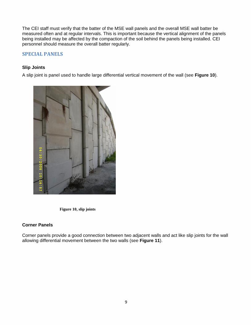
9
The CEI staff must verify that the batter of the MSE wall panels and the overall MSE wall batter be measured often and at regular intervals. This is important because the vertical alignment of the panels being installed may be affected by the compaction of the soil behind the panels being installed. CEI personnel should measure the overall batter regularly.
SPECIAL PANELS
Slip Joints
A slip joint is panel used to handle large differential vertical movement of the wall (see Figure 10).
Figure 10, slip joints
Corner Panels Corner panels provide a good connection between two adjacent walls and act like slip joints for the wall allowing differential movement between the two walls (see Figure 11).
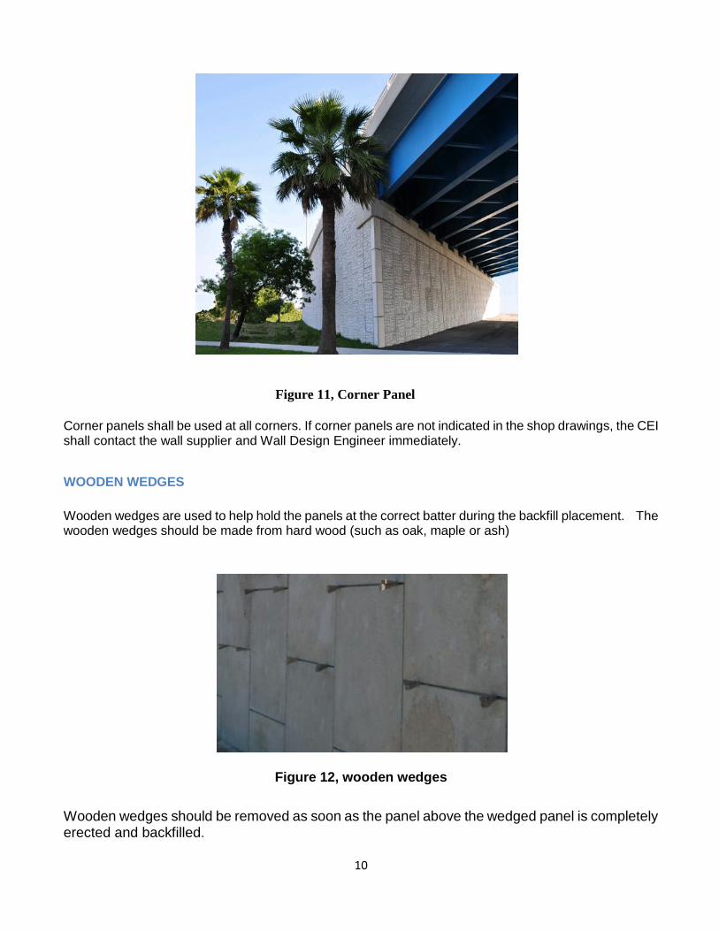
10
Figure 11, Corner Panel
Corner panels shall be used at all corners. If corner panels are not indicated in the shop drawings, the CEI shall contact the wall supplier and Wall Design Engineer immediately.
WOODEN WEDGES
Wooden wedges are used to help hold the panels at the correct batter during the backfill placement. The wooden wedges should be made from hard wood (such as oak, maple or ash)
Figure 12, wooden wedges
Wooden wedges should be removed as soon as the panel above the wedged panel is completely erected and backfilled.

11
PANEL STORAGE Panels should be stored flat and on dunages (see Figure 13). Figure 14 is an example of improperly stored panels. This is done for a couple of reasons; 1) it protects the connections from being bent and damaging the galvanization (see Figure 15) and 2) they should be stored out of the mud to avoid staining the panel face.
Figure 13, Panel Storage
Figure 14, Improper Panel Storage

12
CEI inspectors must verify that all components (panels, reinforcement) are handled, stored and shipped in a manner that prevents, chipping, cracks, fractures, excessive bending stresses. The Department has the right to reject panels with damaged connectors. If the inspector sees bent tabs like those in Figure 15 he should contact his Project Administrator/Engineer immediately. Also, the inspector should point out to the Contractor when the storage of panels is not being done properly.
Figure 15, Damaged Tabs
VIII. SOIL REINFORCEMENT
The soil reinforcement is used to tie the wall to the soil. There are two types of reinforcement: metallic and polymeric reinforcements. The metallic reinforcement should not be bent, torn, galvanization chipped off or otherwise damaged. The polymer reinforcement should not be torn, cut, left in the sun or otherwise damaged. The inspector should check the reinforcement for the required length, size and supplier’s product designation. No equipment should be allowed to run directly on the reinforcement. Typically, the reinforcement is placed perpendicular to the wall face. Any slack in the reinforcement should be removed. The CEI personnel must inspect soil reinforcement for compliance with design drawings and shop drawings i.e. size, length, type of material. CEI staff must Inspect the proper placement of soil reinforcement. Soil reinforcement should not be skewed more than 15 degrees from normal. If reinforcement needs to be skewed more than 15 degrees, notify the Wall Design Engineer, unless the shop drawing clearly indicates such deviation. Soil reinforcement near the top of the wall shall be parallel to the lifts of fill, unless a slight bending (within 15 degrees) is indicated in the shop drawings to accommodate a structure. Soil reinforcement shall not extend into a stabilized subgrade that may require mechanical mixing. Soil reinforcement shall not be cut unless shown in the contract documents or approved by the Engineer.

13
METALLIC REINFORCEMENT (INEXTENSIBLE)
It is the mostly used in permanent MSE wall applications for the Department. Its use is limited when the environmental conditions are highly corrosive. They are made of galvanized steel. The most common are ribbed strips and metallic grid indicated in Figure 17) .
Figure 16, Soil Reinforcement
Figure 17 , Metallic Reinforcement (Inextensible). Left: metallic grid. Right: Ribbed Strips.
POLYMERIC (Geosynthetics)-EXTENSIBLE REINFORCEMENT Geosynthetic reinforcement could be geogrids or geotextiles. They are typically used in temporary walls as well as in permanent walls in corrosive environments and in modular block (segmental) walls. The polymeric reinforcement should have some tension placed in the reinforcement during fill placement to remove slack. The reinforcement should not be connected to the wall until the compacted fill is at or
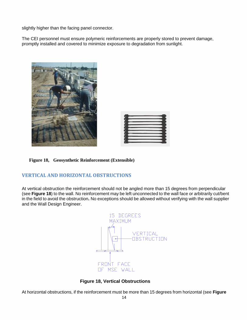
14
slightly higher than the facing panel connector.
The CEI personnel must ensure polymeric reinforcements are properly stored to prevent damage, promptly installed and covered to minimize exposure to degradation from sunlight.
Figure 18, Geosynthetic Reinforcement (Extensible)
VERTICAL AND HORIZONTAL OBSTRUCTIONS
At vertical obstruction the reinforcement should not be angled more than 15 degrees from perpendicular (see Figure 18) to the wall. No reinforcement may be left unconnected to the wall face or arbitrarily cut/bent in the field to avoid the obstruction. No exceptions should be allowed without verifying with the wall supplier
and the Wall Design Engineer.
Figure 18, Vertical Obstructions
At horizontal obstructions, if the reinforcement must be more than 15 degrees from horizontal (see Figure

15
19) the Wall Design Engineer must be contacted. It may need additional reinforcement length to meet design requirements. Also when clearing horizontal obstructions, the reinforcement should be smoothly curved around the obstruction. The reinforcement should not be kinked at any time. There should also be a minimum of 4 inches of cover between the obstruction and the reinforcement. Table 1 shows the recommended transition distance X (see "X" in Figure 20) from the point of connection to provide a smooth curve of the reinforcement with an offset of d (see "d" in Figure 20). If these distances cannot be achieved the wall supplier should be contacted to check the design.
Figure 19, Horizontal Obstructions
Figure 20, Transition Distances for horizontal obstructions
Table 1. Transition Distances
The CEI staff must verify the soil reinforcement straps are not cut and that the 15 degrees skew angle is not exceeded. The CEI staff must ensure that the Contractor submit shop drawings approved by the Wall Design Engineer detailing any cutting of soil reinforcement. No cutting in the reinforcement may be allowed until these shop drawings are submitted and approved. The CEI must also ensure that the Contractor submit shop drawings approved by the Wall Design Engineer which detail construction of the

16
wall around obstructions including details addressing conflicts between the soil reinforcement and any obstructions within the wall volume. The CEI must contact the Wall Design Engineer immediately if cutting of reinforcement, excessive transition angles or details around obstructions are not properly addressed in the shop drawings.
REINFORCEMENT STORAGE Like the panels the reinforcement should be stored on dunage (see Figure 21) and carefully handled to prevent damage. Damage may include bending of the reinforcement and damaging the galvanization.
Figure 21, Reinforcement Storage
WALL/REINFORCEMENT CONNECTION Connection devices are incorporated into the panels to attach the soil reinforcement. In tab connection devices the nut should be placed on top (with the head of the bolt underneath) to make sure it is going to be placed and tightened.
Figure 22, Reinforcement Connections

17
IX. FILTER FABRIC AND JOINTS A geotextile filter fabric is used to cover all the joints between panels. See Figures 23 and 24.
Figure 23, Filter Fabric installation Fig 24, Filter Fabric installed at the joints
The filter fabric is placed on the backside of the panels. This keeps the backfill soil from being eroded through the joints and provides drainage. The adhesive should be applied to the panel before affixing the geogrid to the panel. It is important that the joint opening widths be within the specs, and to place the filter fabric properly. Significant loss of backfill after few years of service may occur if the fabric and joint system are not built properly (See Figure 25 ). CEI personnel must ensure that the filter fabric and the panel spacers are acceptable and that the filter
fabric is properly placed in all joints.

18
Figure 25, Loss of backfill through improperly constructed joint and filter fabric (Left: backfill washed through joint deposited next to the slip panel. Right: Void as observed from the top of wall)
X. COPING/BARRIER Coping is used to tie in the top of the wall panels and to provide a smooth pleasing finish to the wall top. Coping/barriers can be cast-in-place or prefabricated segments. For precast units a leveling course of concrete is placed prior to setting the units in place (see Figure 28). This provides the vertical control needed. Barriers are tied together and strengthened against vehicle impact by a junction (moment) slab (see Figures 27 and 28).
Figure 26 , coping

19
Figure 27, Barrier with Slab. Cast-in-place
Figure 28, Precast Barrier. Indicated in red is the leveling concrete.
When precast coping is used, CEI personnel must verify that top panels have dowels that will extend into the cast-in-place Buildup concrete (refer to the wall coping Design Standard indices). When cast-in-place coping is used CEI personnel must verify that a one-half inch minimum preformed expansion material between wall panels and cast-in-place concrete is placed (refer to the wall coping Design Standard indices)
XI. ABUTMENT CHEEK WALLS When abutments are on a deep foundation, a bond breaker is needed between the MSE Wall panel and the cheek wall (see Figure 29). If this is not done, when the wall settles and the abutment doesn‘t, it creates a tension load in the cheek wall and the panel. This eventually leads to one or both to crack (see Figure 30 and Figure 31). When rough panel finishes are used (such as shown Figure 30) a heavy/thick bond breaker is required. In cases such as this a thin paper bond breaker forms to the panel irregularities and the panel locks into the poured concrete. With smooth panel finishes a paper bond breaker would

20
usually be sufficient.
Figure 29, Bond Breaker
Figure 30, Cracked Panel and Cheek Wall Figure 31, Tension Break in Cheek Wall
XII. SELECT MSE WALL BACKFILL The select backfill must meet the specification requirements for gradation, electro-chemical, soil plasticity properties and organic content. It must be free drainage materials, having therefore a limited amount of fines (material passing sieve #200). Please check the specs, section 548 for the current gradation limits and the maximum amount of fines permissible. Typical materials acceptable will fall within the AASHTO classification of A-1, A-3 and A-2-4 (towards the lower end of percentage passing #200 sieve; close to the A-3 classification). In special cases, the plans and/or shop drawings may require higher soil friction angles to meet stability requirements. In these cases the Contractor is required to perform direct shear tests to proof that the material supplied meets the design requirements. As a minimum the Contractor needs to supply three (3) direct shear tests (performed in accordance with AASTHO T-236) per soil type. The lowest soil friction angle obtained from the three direct shear tests must be equal or exceed the value indicated in the

21
plans/shop drawings. These special testing will be required in the following cases:
For A-3 and A-2-4 materials: When the assumed or required design soil friction angle is greater than 30o.
For limerock material (which may be used in some projects in South Florida): When the assumed or required design soil friction angle is greater than 34o.
PLACING BACKFILL
The select backfill lift should be placed parallel to the wall and starting approximately three (3) feet from the back of the wall panels. The backfill should be placed in 6" compacted lifts (it may be helpful to mark your lifts on the back side of the wall panels). The fill is then leveled by machinery moving parallel to the wall, windrowing the material toward the reinforcement ends. This action works out any slack in the reinforcement then locking the reinforcement and the panels in position. Once this has been accomplished, fill is then placed within 3‘ behind the wall by windrowing the material except for the initial layer, for which the fill must be brought up uniformly for the whole layer.
COMPACTION Compaction equipment used within three (3) feet of the wall should be a vibratory roller or plate weighing less than 1000 pounds. From beyond three (3) feet of the wall facing panels a roller up to 8 tons may be used subject to satisfactory performance (see Figure 32). A smooth wheeled or a rubber-tired roller is also acceptable. Compactors, which employ a foot such as a sheepsfoot (see Figure 32) or grid rollers, are not acceptable.
Figure 32, Compaction Equipment
Backfill compaction shall be performed in such a way that the roller (up to 8 ton in weight) shall move in a direction parallel to the wall facing panels and proceed from a distance not less than three feet behind the wall facing panels and work toward the end of the soil reinforcement away from the wall facing (see Figure 51). The moisture content of the backfill material prior to and during compaction shall be uniformly

22
distributed throughout each layer of material. Backfill material shall have placement moisture content on the dry side of the Optimum Moisture content. If additional water is required for the material, the water must meet the specification requirements.
DAYS END At the end of each day's operation, the Contractor shall shape the last level of backfill as to permit runoff of rainwater away from the wall face or shall provide a positive means of controlling runoff away from the wall such as temporary pipes, etc. Failure to do this could result in wall damage due to hydrostatic pressure or the erosion of material from around the soil reinforcement (see Figure 33).
Figure 33, Wash Out From Around Reinforcement

23
BACKFILL IN FRONT OF WALL
The area in front of the wall and around the leveling pad should be backfilled as soon as practically possible. A strong rainstorm could cause heavy flow along the wall. This could cause soil erosion and undermining of the leveling pad and the wall (Figure 34).
Figure 34, Undermining of leveling pad
XIII. MISCELLANEOUS POINTS
CONSTRUCTION LOADS Before the actual start of construction of the wall, the various parts of the plans (shop drawings, drainage, lighting, etc.) need to be compared to the contract wall plans to check for conflicts. A conflict may not have been noticed in the design stage. If the plans show heavy loads on the wall and the shop drawings do not indicate it,the wall supplier should be questioned. The wall supplier may not have seen a full set of plans. Due to this, he may have missed loadings from various types of structures. If he did not take these loads into consideration, the wall could fail. This also can be temporary loads that the contractor may impose that was not accounted for (see Figure 35)

24
Figure 35, Construction Load
DRAINAGE STRUCTURES Design for drainage structures in the wall mass are also sometimes missed by the wall supplier. It is not acceptable to just cut the reinforcement (see Figure36). Sometimes it is necessary to angle the reinforcement, but never angle them more than 15 degrees from the perpendicular to the wall without verifying adequacy with the wall supplier and the Wall Design Engineer. If the space between the drainage structure and the wall panel is very limited to allow proper compaction, consideration may be given for using flowable fill in such confined areas. Please refer to section XIV of this handbook for more information, requirements and limitations regarding the use of flowable fill.
Figure 36, Not Proper Avoidance of Drainage Structure
Retention ponds located next to MSE walls need to be checked. Check that the wall is protected from scour by the drainage pipes. It has happened on projects where the drainage plans and the wall plans were not coordinated.

25
EXCAVATIONS ADJACENT TO MSE WALLS Excavations next to existing MSE Walls can cause settlement and undermining problems with the wall. As the area is excavated in front of the wall, the material under the wall moves into the excavation. Consequently the wall settles leaving a large gap at the panel joints (see Figure 37 and Figure 38). This can also happen if a trench is dug before erecting the wall without properly compacting the trench backfill. As can be seen in Figure 39 a drainage pipe was installed prior to erecting the wall. Once the rains came and softened up the soils the material under the wall moved into the pipe trench that was not properly compacted.
Figure 37, Settlement from Excavation Figure 38, Joints Opening from Settlement
. Figure 39, Wall Failure from Exterior Excavation

26
TEMPORARY WALLS Temporary walls with temporary wall facings are typically used in phased construction to allow traffic above it while a permanent embankment or other structures is constructed in front of it. In this particular
wall type the reinforcement used is typically geogrids but other approved systems exist. See Figure 40. .
Figure 40, Temporary during phased construction
TEMPORARY WALL FACING
When large settlements are expected Temporary wall facings are used at times to handle large settlements that the permanent wall facings could not handle. The wall is built using a temporary facing such as fabric wrapping with tabs sticking out for eventual connection of a permanent facing (see Figure 41). The permanent facing is not attached until the majority of settlement has occurred.
Figure 41, Temporary and Permanent Wall Facings

27
XIV. CONSTRUCTION
The construction sequence is typically as follows:
First, the site is cut to grade and all unsuitable material is removed. The site is proof rolled to delineate any loose and/or unsuitable materials. Compact any loose material and remove and replace any unsuitable material found. The proof rolling is accomplished by at least 5 passes of a vibratory roller weighing a minimum of eight tons.
1 The leveling pad excavation is dug (see Figure 42)
Figure 42, Preparing Site, Proof Roll & Excavate Footing
4 The leveling pad is placed (see Figure 43). The concrete is allowed to cure a minimum of
12 hours before any panels are placed.
Figure 43, Place Concrete Leveling Pad
5. The first row of panels are placed on the leveling pad and braced (see Figure 44). Adjacent panels
should be clamped together to prevent individual panel displacement. The panels should be set with a backward batter, typically +1/8 inch per foot. This may allow the panel to be vertical once fill is placed and compacted against it. The batter is adjusted for the site conditions e.g. backfill properties, the finer sand may require a larger batter.
Figure 44, Install & Brace 1st Row of Panals
6. Attach filter fabric over the joints (See Figure 45). An adhesive is used to hold the filter fabric across
all of the panel joints. The adhesive should be applied on the panel next to the joints then the filter fabric is placed over the joint, because applying adhesive on the filter fabric tends to clog the filter fabric.

28
Figure 45, Attach Filter Fabric
7. The select backfill is then placed and compacted to the level of the first row of connections. The compacted fill should be at or slightly higher than the panel connections (see Figure 45). On the initial row of panels (and only the initial row of panels) the backfill is not placed against the panel until the first row of reinforcement has been connected and the initial 6 inch layer of compacted fill is placed on the reinforcement. This is to keep the bottom of the panels from "kicking out". From that point, the backfill is brought up uniformly from the back of the panels to the end of the reinforcement.
Figure 46, Fill in 6” Lifts to Reinforcement Figure 47, Connect and Tighten Reinforcement
8. The reinforcement is then placed typically perpendicular to the wall panel and the connection (see Figure 47). Any slack in the reinforcement should be removed to avoid excessive panel movement. With polymeric reinforcement some tension should be applied to the reinforcement by means of a kicker tension device or a rod (see Figure 48).
Figure 48, Tightening polymer Reinforcement

29
9. Then another row of wall panels is placed with the proper batter.
10. The select backfill is then placed (see Figure 49) in 6 inch compacted lifts until the fill is at or
slightly above the next set of connections. Any additional water needed for compaction must meet the specification requirements. The backfill is placed parallel to the wall starting approximately three (3) feet from the back of the panels. The fill is then windrowed toward the reinforcement ends (see Figure 50). Once this is complete, the fill is windrowed from the three (3) foot point back toward the panels (see Figure 51).
Figure 49, Typical Edge Fill Placement Figure 50, Typical Edge Fill Placement (Plan View) (Plan View)
11. The compaction equipment rolls parallel to the wall facing. Compaction starts at least three (3) feet from the wall and works toward the end of the reinforcement (see Figure 51).
Figure 51, Initial Compaction Figure 52, Final Compaction
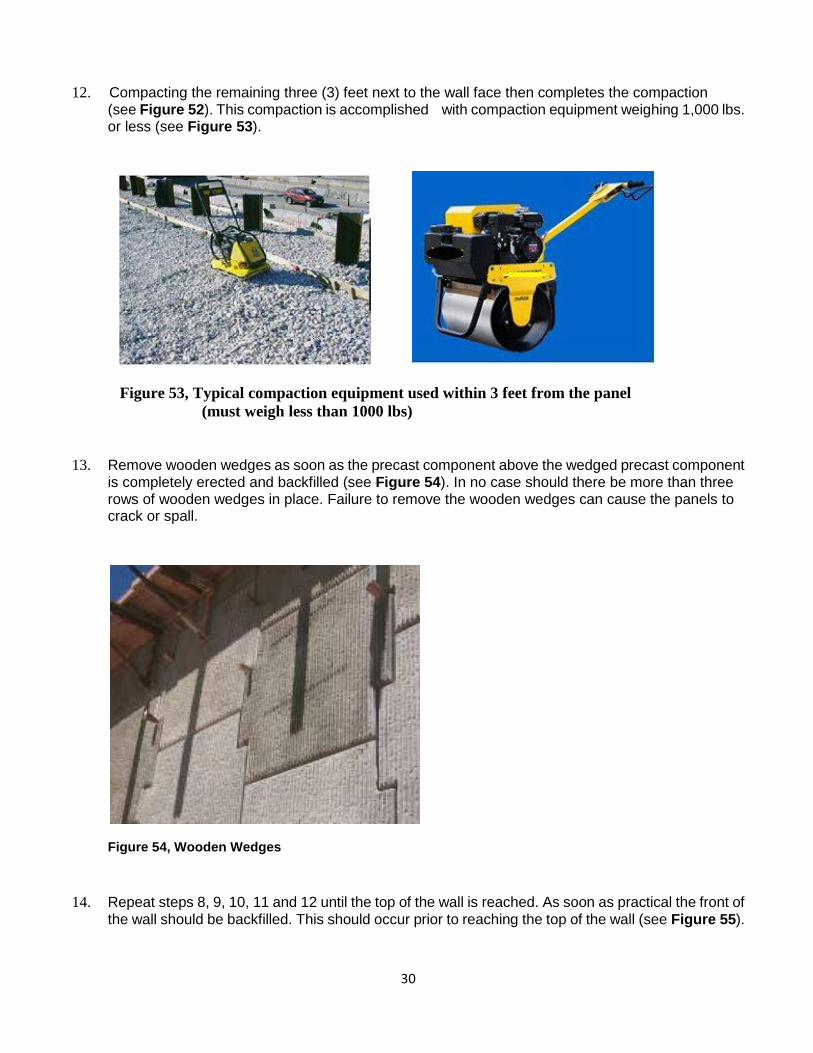
30
12. Compacting the remaining three (3) feet next to the wall face then completes the compaction (see Figure 52). This compaction is accomplished with compaction equipment weighing 1,000 lbs. or less (see Figure 53).
Figure 53, Typical compaction equipment used within 3 feet from the panel
(must weigh less than 1000 lbs)
13. Remove wooden wedges as soon as the precast component above the wedged precast component is completely erected and backfilled (see Figure 54). In no case should there be more than three rows of wooden wedges in place. Failure to remove the wooden wedges can cause the panels to crack or spall.
Figure 54, Wooden Wedges
14. Repeat steps 8, 9, 10, 11 and 12 until the top of the wall is reached. As soon as practical the front of
the wall should be backfilled. This should occur prior to reaching the top of the wall (see Figure 55).

31
Figure 55, Place Backfill in Front of the Wall as Soon as Practical
15. The coping is then placed on the top of the wall. The wall is completed when the coping is properly installed on top of the wall.
EXCAVATIONS NEAR EXISTING MSE WALLS
An MSE wall is a large spread footing and when excavations occur close to the wall, a bearing capacity failure could occur. This is especially true when excavating below the existing water table. Inspectors should document and report any contractor excavation operations. There have been bad experiences of existing walls being affected by Contractor’s temporary excavations. This could particularly occur on phased construction in vicinity of temporary walls. Any excavation not indicated in the plans, whether supported or unsupported, close to an existing wall needs to be analyzed and checked by the Engineer of Record and reviewed by the District Geotechnical Engineer. Also, if dewatering is planned near the wall, it should be analyzed by the Engineer of Record and reviewed by the District Geotechnical Engineer. The CEI shall not allow excavations in close proximity in front of the wall once the wall construction has started without the Engineer of Record's approval. Also, excavations in front of a wall should not be allowed without protection to the wall (i.e. sheet piles, etc.).
BACKFILL TESTING AND ACCEPTANCE
The quality control of the backfill is performed through laboratory and field testing. Lab testing is performed on soil material proposed to be used as a MSE wall select backfill material to determine the grain size distribution properties, the electro-chemical (corrosion potential) properties, the organic content, the plasticity indices and the compaction properties. Please refer to specification 548 for test frequency and acceptable ranges in test results. From the compaction properties testing, a maximum dry density is determined in the lab. The specifications dictate the minimum percentage of compaction in relation to the maximum density determined in the lab, that is required for the retaining wall volume (reinforced mass). In the field densities will be determined by the contractor Quality Control (QC) personnel. The Engineer/CEI staff will perform verification testing (VT) as well.

32
FIELD DENSITY REQUIREMENTS
The CEI staff must verify that the backfill is placed and compacted in accordance with plans and specifications and that the Earth Density books are properly prepared. Check that water used for soil compaction is in compliance with section 923 (No salt or brackish water). Do not allow thick lift compaction as lifts thicker than 6" (150 mm) require more energy to compact and may move the panels out of alignment. [Spec. 548-6] The MSE wall backfill shall have the following minimum dry densities:
The material beyond 3 ft from the back of the panels shall have a minimum dry density of 95% of the maximum density determined in the Modified Proctor test, in accordance with the FM 1-T 180 procedure.
The material within 3 ft from the back of the panels shall have a minimum dry density of 90% of the maximum density determined in the Modified Proctor test, in accordance with the FM 1-T 180 procedure.
If the Material classifies as A-2-4 or A-3 at the Contractor’s option, the MSE wall backfill may be compacted to the following alternative criteria:
Material beyond 3 ft from the back of the panels: minimum dry density of 100% of the maximum density determined in the Standard Proctor test, in accordance with the AASHTO T-99 method C procedure.
The material within 3 ft from the back of the panels shall have a minimum dry density of 95% of the maximum density determined in the Standard Proctor test, in accordance with the FM 1-T 99 method C procedure.
In the 3 ft zone within the back of the panels the compactor equipment weight cannot exceed 1000 lbs. The reason to limit the weight of the equipment and a lower density requirement in this zone is to minimize movement of the panels. Note: For pipe backfill within the MSE wall reinforcement volume, the compaction requirements for the MSE wall backfill describe above will apply. LOTS A LOT is defined typically as a single lift of finished backfill not to exceed 500 ft in length. The maximum thickness of compacted material allowed by the specifications in a lift is 6 inches. The contractor is required to perform at least 1 QC field density test per LOT. The Department will perform 1 VT field density test every 4 LOTs. Since the material within 3 feet from the wall has a different compaction requirement (less) than the rest of the reinforced volume and the equipment is different, there will be two LOTS in any given 500 ft of wall: One for the MSE wall select backfill within 3 ft from the wall and another for the MSE walls select backfill material beyond 3 ft from the panels. See Figure 56. Therefore in any given 500 ft length of wall of Figure 56, the Contractor QC inspector is to perform 1 field density test for every lift in the zone within 3 ft of the panels, and 1 field density test for every lift in the zone beyond the 3 ft from the panels.

33
Figure 56. In this case, in every 500 ft, there are two LOTS for the MSE wall backfill in addition to the LOT for the embankment, per lift.
In the case of parallel walls where the reinforcement overlaps, only one LOT is necessary, if the two adjacent areas are compacted in the same operation, following the same procedures and using the same
backfill material. See Figure 57.
Figure 57. Parallel walls, overlapping reinforcement
In the case of Figure 57, for every 500 ft of length, if the same material and same procedures are used, then for every 500 ft, 3 density tests will be required per lift: 2 for the two separate areas within 3 ft from the panels and 1 for the middle area.
If there is a gap between reinforcements, and this gap is not greater than 8 ft, and it is built with the same material, and compacted in the same manner, the two adjacent MSE wall backfills (excluding the 3 ft
within the panels) and the gap may be considered as one LOT. (Figure 58)

34
Figure 58 . Paralell walls, with a narrow gap between reinforcements
In bridge approaches the number of LOTS may be optimized by considering contiguous walls as one continuous “horseshoe” shaped wall. See Figure 59 for a plan view:
Figure 59 . Horseshoe shaped walls at bridge approaches

35
FLOWABLE FILL The FDOT specifications allow the use of flowable fill as MSE wall backfill material when it is specified in the plans. Flowable fill is a mixture of Portland cement, fly ash, fine aggregate, admixture and water. Flowable fill contains a low cementitious content for reduced strength development. When flowable fill is used the metallic wall components (including metallic soil reinforcements) must not be in partial contact with the flowable fill. If the metallic components contact the flowable fill, the metallic components must be completely encapsulated by the flowable fill. Metallic elements partially embedded in cementitious materials have been found to be susceptible to corrosion. A type of low density flowable fill called cellular concrete is also allowed by the specifications. A cellular flowable fill is a low density concrete made with cement, water and preformed foam to form a hardened closed cell foam material. Cellular concrete flowable fill may also contain fine aggregate, fly ash, slag and admixtures. The use of cellular concrete may be very convenient when there is a need for relatively narrow widenings in front of an existing retaining wall. Figure 60 illustrates a wall constructed with full height panels (known as tilt panels) using cellular concrete as backfill next to an existing cantilever concrete retaining wall.
Figure 60, Cellular Concrete Wall

36
APPENDIX A CHECK LIST The following is a general checklist to follow when constructing a Mechanically Stabilized Earth wall (MSE
wall). The answer to each of these should be yes unless plans, specifications or specific approval has been given
otherwise.
YES NO
1. □ □ Has the contractor submitted wall shop drawings?
2. □ □ Has the contractor submitted signed and sealed select backfill certification (showing that it meets the gradation, density and corrosion and other soil requirements)?
3. □ □ Has the contractor supplied a Certificate of Compliance certifying that the wall
materials comply with the applicable sections of the specifications? Has the contractor supplied a copy of all test results performed by the Contractor or his supplier, which are necessary to assure compliance with the specifications?
4. □ □ Has the contractor furnished a copy of any instructions the wall supplier may have furnished?
5. □ □ Have the shop drawings been approved?
6. □ □ Did the contractor receive the correct panels (shape, size and soil reinforcement
connection layout) per the approved shop drawings?
7. □ □ Did the contractor receive the correct reinforcement (proper length, size, and proper product designation)?
8. □ □ Have the panels and the reinforcement been inspected for damage as outlined in the specifications?
9. □ □ If any panels or soil reinforcement were found damaged have they been rejected or repaired in accordance with the specifications?
10. □ □ Are the panels and the soil reinforcement properly stored to prevent damage?
11. □ □ Has the MSE wall area been excavated to the proper elevation?
12. □ □ Has the area been proof rolled per the specifications (a minimum of five (5)
passes by a roller weighing a minimum of 8 tons)? 13. □ □ Has all soft or unsuitable materials been compacted or removed and replaced? 14. □ □ If the contractor is using any water in the MSE wall area does it meet the
requirements shown in the specifications?
15. □ □ Has the leveling pad area been properly excavated?
16. □ □ Has the leveling pad been set to the proper vertical and horizontal alignment?
17. □ □ Has the leveling pad cured for a minimum of 12 hours before any panels are
set?

37
YES NO
18. □ □ Is the first row of panels properly placed? Do they have proper spacing, bracing,
tilt and where required, do they have the spacers installed?
19. □ □ Has the proper filter fabric and adhesive been supplied?
20. □ □ Is the filter fabric being properly placed over all the panel joints?
21. □ □ Is the adhesive being applied to the panel, and then the filter fabric being
placed?
22. □ □ Is the filter fabric being stored properly (stored out of the sunlight and protected from UV radiation)?
23. □ □ Is the contractor using the correct panels (correct size, shape and with the proper number of connections) for that panel's wall location and elevation?
24. □ □ Is the fill being placed and compacted in 6 inch thick lifts?
25. □ □ Is the equipment being kept off of the soil reinforcement until a minimum of 6
inches of fill is placed?
26. □ □ Are the lifts being placed by the proper method and sequence
27. □ □ Is the fill being compacted by the correct equipment and in the correct pattern?
28. □ □ Are the proper compaction requirements being met? Are the minimum percentage compaction
achieved within 3 feet from the panels and beyond three feet from the panels?
28. □ □ Are separate densities (separate LOTs) being taken for the 3 ft from the
panels and beyond 3 ft from the panels ?
29. □ □ Is the fill being brought up to or slightly above the soil reinforcement elevation
before the reinforcement are connected? 30. □ □ Is the soil reinforcement being properly connected (connections tight and all of
the slack in the soil reinforcement removed)? 31. □ □ Are the soil reinforcements in the proper alignment? 32. □ □ Is the vertical and horizontal alignment being checked periodically and adjusted
as needed?
33. □ □ Are the correct reinforced length and sizes installed per shop drawings 34. □ □ Are the constructed panel joints being checked periodically to verify the specification limits
are met?
35. □ □ Is the contractor removing the wooden wedges as per the specifications? (The wooden wedges shall be removed as soon as the panel above the wedged panel is completely erected and backfilled.)

38
YES NO
36. □ □ At the end of each day's operation is the contractor shaping the last level of backfill as to
permit runoff of rainwater away from the wall face or providing a positive means of controlling runoff away from the wall such as temporary pipe, etc?
37. □ □ Has the contractor backfilled the front of the wall?
38. □ □ Is the correct coping being installed?

B-1
APPENDIX B
MSE WALL CONSTRUCTION DO'S AND DON'TS 1. Review approved shop drawings.
2. Review Mechanically Stabilized Earth (MSE) Wall Inspector's Handbook.
3. Confirm foundation has been compacted properly in accordance to the specifications.
4. Verify leveling pad elevations.
5. Confirm receipt of Certificate of Compliance from the wall company.
6. Confirm receipt of signed and sealed of proposed select backfill fill materials. Confirm backfill materials
have been tested and approved before it is brought to the job site.
7. Inspect panels.
8. Inspect soil reinforcement for damage.
9. Reject all panels that are not in compliance with the plans and specifications.
10. Ensure panels, soil reinforcement and filter fabrics are properly stored to prevent damage.
11. Ensure all piles in the reinforced fill are wrapped with two independent layers of 6 mil plastic with
lubricating oil between the layers.
12. Install panels in accordance to shop drawings, plans and specifications.
13. Place and properly compact fill in accordance with plans and specifications.
14. DO NOT use thick fill lifts. Fill lifts thicker than 6" compacted lifts require more energy to compact and
may move the panels out of alignment.
15. Use corner panels at all corners. If corner panels are not indicated on the plans, the wall supplier and the
Wall Design Engineer should be notified.
16. Verify installed reinforcement lengths behind panel.
17. Soil reinforcement should not be skewed more than 15 degrees from normal. If reinforcement needs to be
skewed more than 15 degrees, notify the wall supplier and the Wall Design Engineer.
18. Check the batter of the panels often. Adjust accordingly. The vertical alignment of the panels below the
panels being installed may be affected by the compaction of the soil behind the panels being installed.
19. Check overall batter regularly.
20. Water for soil compaction shall be in compliance with Section 923. NO saltwater or brackish water is to
be used.
21. When attaching filter fabric to the back of the panels, the adhesive shall be applied to the panel NOT the
filter fabric.
22. Remove wooden wedges as soon as possible.
23. If precast coping is used, ensure top panels have dowels that will extend into the cast-in-place Buildup
concrete.
24. DO NOT allow excavations in close proximity in front of the wall once the wall construction has started.
If excavations are required in front of the wall, the Engineer of Record's approval will be obtained before
the excavation is started. Also, excavations in front of the wall should not be allowed without protection
to the wall (i.e. sheet piles, etc.)
25. Soil reinforcement near the top of the wall shall be parallel to the lifts of fill. Soil reinforcement shall not
extend into the stabilized subgrade that may require mechanical mixing.
26. DO NOT CUT soil reinforcement to avoid obstructions without the approval of the Wall Design Engineer.
27. Place one-half inch minimum preformed expansion material between wall panels and cast-in-place
concrete

C-1
APPENDIX C OUT-OF-TOLERANCE CONDITIONS AND POSSIBLE CAUSES CRITERIA
The following is taken out of FHWA‘s Publication —DESIGN AND CONSTRUCTION OF
MECHANICALLY STABILIZED EARTH WALLS AND REINFORCED SOIL SLOPES- Publication No.
FHWA-NHII-10-025, November 2009.
Table 11.4. Out-of-Tolerance Conditions and Possible Causes
MSE structures are to be erected in strict compliance with the structural and aesthetic requirements of the plans,
specifications, and contract documents. The desired results can generally be achieved through the use of quality
materials, correct construction/erection procedures, and proper inspection. However, there may be occasions
when dimensional tolerances and/or aesthetic limits are exceeded. Corrective measures should quickly be taken
to bring the work within acceptable limits. Presented below are several out-of-tolerance conditions and their
possible causes.
CONDITION POSSIBLE CAUSE
1. Distress in wall:
a. Differential settlement or low spot in
wall (Cause 1a & b apply)
b. Overall wall leaning beyond vertical
alignment tolerance (Cause 1 a & b).
c. Spalling, chipping, or cracking of
facing units (Cause 1 a – e apply) (e.g.,
from panel to panel contact or
differential movement of modular
block facing units).
.
2. First panel course difficult
(impossible) to set and/or maintain level..
3. Wall out of vertical alignment
tolerance (plumbness), or leaning out.
1.a. Foundation (subgrade) material too
soft or wet for proper bearing.
.b . Fill material of poor quality or not
properly compacted..
c. Inadequate spacing in horizontal
and vertical joints.
d. Use of improper bearing pads
e. Stones or concrete pieces between
facing units (e.g. units not clean
or used to face units)
2.a. Leveling pad not level
3.a. Panel not battered sufficiently.
b. Oversized compaction equipment
working within 3 foot zone of
back of wall facing panels.
c. Backfill material placed wet of
optimum moisture content.
Backfill contains excessive fine

C-2
4. Wall out of vertical alignment
tolerance (plumbness) or leaning in.
5. Wall out of horizontal alignment
tolerance, or bulging.
6. Panels do not fit properly in their
intended locations.
materials (beyond the
specifications for percent of
materials passing a No. 200
sieve).
d. Backfill material pushed against
back of facing panel before being
placed and compacted above
reinforcing elements.
e. Excessive compaction of
uniform, medium-fine sand (more
than 60 percent passing a No. 40
sieve).
f. Backfill material dumped close
to free end of reinforcing
elements, then spread toward
back of wall, causing
displacement of reinforcements
and pushing panel out.
g. Shoulder wedges not seated
properly.
h. Shoulder clamps not tight.
i. Slack in reinforcement to facing
connections.
j. Inconsistent tensioning of
geosynthetic reinforcement to
facing
k. Localized over-compaction
adjacent to MBW unit.
4.a. Excessive batter set in panels for
select granular backfill material
being used.
5.a. See Causes 3c, 3d, 3e, 3j, 3k.
Backfill saturated by heavy rain
or improper grading of backfill
after each day’s operations.
6.a. Panels are not level. Differential
settlement (see Cause 1).
b. Panel cast beyond tolerances.

C-3
7. Large variations in movement of
adjacent panels.
7.a. Backfill material not uniform.
b. Backfill compaction not uniform.
c. Inconsistent setting of facing
panels.

Signalization, GL-12A, FY 2014/2015, Page 1 of 5
FY 2015/2015 QC Category No. 12A STATEWIDE INSPECTION GUIDELIST
Signalization GENERAL
1. Use the FDOT Minimum Specifications for Traffic Control Signals and Devices (MSTCSD), the FDOT’s Submittal Data – Traffic Control Equipment form (750-010-02) and the approved shop drawings to confirm items installed are listed on the Approved Product List (APL), or when APL listing is not required to meet the MSTCSD and Specs. [Spec. 603]
2. A pre-installation meeting should be conducted with the signal Contractor,
maintaining agency, etc. to discuss signalization issues. [CPAM 3.1]
MAST ARMS
3. Mast arm shop drawings submitted in accordance with approved schedule well in advance of installation due to long lead time (3-6 months). [Good Practice]
4. Confirm Drilled Shaft Installation Plan is submitted and approved. [Spec.
455-15]
5. Mast arm foundations constructed in accordance with the Plans, Special Provisions, and Specifications. [Spec. 455-15]
6. Upon delivery, verify mast arm dimensions match the shop drawings and
plans. [Good Practice]
7. Wire the signal cable in the mast arms in accordance with the plans, specifications and/or the maintaining agency’s color code. [Plans, Spec. 632]
ACCEPTANCE PROCEDURES (SECTION 611)
8. Witness completion of all field testing with the Contractor’s representative
and, with a representative from the maintaining Agency, if required. [Spec. 611-4]
9. Warranty Period: Meet with the signal Contractor and the maintaining agency
to discuss method of handling warranty period. Record model and serial numbers of electronic equipment. Establish a method to track all trouble calls during the warranty period. Notify the Contractor of equipment malfunctions during the life of the contract and document the Contractor’s response times. Record and track all equipment malfunctions and repairs during the life of the contract. Provide a letter to the maintaining agency and the Contractor documenting the beginning and anticipated end of the warranty period. [Spec. 611-5, Good Practice]

Signalization, GL-12A, FY 2014/2015, Page 2 of 5
SIGNAL INSTALLATION GROUNDING (SECTION 620)
10. Installation of the required number and length of ground rods to be observed.
[Spec. 620-3]
11. The resistance of each ground rod is to be measured and recorded (if required by contract Specifications) and the buried location of each ground rod is to be staked. [Spec. 620-3]
12. Ensure that all separately grounded elements at an intersection are bonded
to form an intersection grounding network. [Spec. 620-3, Index 17736]
CONDUIT AND SIGNAL AND INTERCONNECT CABLE (SECTIONS 630 AND 632)
13. Conduit used is the proper type for the type of installation being performed. The conduit is installed at the proper depth. [Spec. 630, Index 17721]
14. The proper number of conduit stub-outs, including spares, is provided
through the cabinet base. [Plans and Index 17841]
15. All conduit trenches are appropriately backfilled. [Index 17721, Spec. 630-3.].
16. Seal conduit ends in a controller base, pole, pull box, junction box, or
pedestal with approved moisture resistant material approved by the Engineer. [Spec. 630-3.5, Index 17721]
17. Signal cable meets requirements. [Spec. 632]
18. The signal cable is to be installed in continuous lengths between controller
cabinets, disconnect hangers (or signal heads for non-span wire installations), pedestrian signal heads, and pedestrian detectors. [Spec 632-3]
19. The communication cable is to be installed in continuous lengths to and
between controller cabinets and junction boxes. [Spec. 633-3.2]
20. The signal cable is to be properly attached to the messenger wire. [Index 17727]
21. Pull wire or cord is installed per [Spec 630-3.1].
PULL and FIBER OPTIC BOXES
22. Verify that box is listed on Approved Product List (APL) and is marked with the APL certification number. [Spec. 635-2]

Signalization, GL-12A, FY 2014/2015, Page 3 of 5
23. All pull and fiber optic boxes shall have a 1’-0” wide and 6” deep concrete aprons sloped away from box. [Index 17700]
24. For fiber optic pull boxes, install ground rods as required and shown in the
plans. [Spec. 630-3.1; Index 17700]
25. Store a total of 200 feet of fiber optic cable in fiber optic splice boxes. [Index 17700]
26. Store 50 feet of spare fiber optic cable in fiber optic pull boxes [Index 17700]
27. Do not place the pull or fiber optic boxes in roadways, driveways, parking
areas, ditches, or public sidewalk curb ramps [Spec. 635-3.2]
28. Ensure that all pull box covers include words describing the application for which it is to be used, such as “FDOT TRAFFIC SIGNAL” (signalized intersection applications), “FDOT FIBER OPTIC CABLE (fiber optic cable applications), FDOT ELECTRICAL (other electrical applications), FDOT LIGHTING (highway lighting applications), FDOT TRAFFIC MONITORING (traffic monitoring applications), or text as shown in the plans permanently cast into their top surface. [Spec. 635-2.2.2]
29. Never place expansion material around pull boxes in sidewalk. The pull box
must bond to the sidewalk to avoid differential settlement. [Good Practice.]
SPAN WIRE ASSEMBLY (SECTION 634)
30. Span wire, fiberglass insulators, and associated hardware comply with spec. and installation requirements. [Spec. 634-2, 634-3, Index 17727, Plans]
31. Span wires to be of one continuous length with no splices except where an
insulator is required. [Spec. 634-3.3]
32. Ensure the span wire assembly is installed with the correct amount of sag. [Spec. 634-3.3(e)]
PRESTRESSED CONCRETE POLES (SECTION 641)
33. The poles are set to the depth specified in the [plans.]
34. The oval eye bolts are located in accordance with the pole guide schedule
[Plans, Shop Drawings]
35. FDOT approved material is used for the footing. [Spec. 641-4]
36. The area around the pole is properly backfilled and tamped. [Spec. 641-4]

Signalization, GL-12A, FY 2014/2015, Page 4 of 5
37. The pole is installed out of plumb at the correct angle of rake. [Mfgr’s Rec.]
SIGNAL HEAD ASSEMBLIES (SECTION 650)
38. Verify that the Light Emitting Diodes (LEDs) modules are listed on the APL.[Spec. 650-2]
39. Two each ¼” diameter weep holes are drilled in the bottoms of each signal
head assembly. [Spec. 650-3.8, Index 17727]
40. Traffic signal heads are installed in the proper location, aimed properly, and set with the proper horizontal and vertical clearances. [Spec. 650-3]
41. For vertically mounted 5-section clusters, construct the signal assembly so
that door hinges are located along the outside edges of the complete signal assembly and each section opens away from the horizontally adjacent section. [MSTCSD Section A650-1]
PEDESTRIAN SIGNALS (SECTIONS 653 AND 665)
42. Pedestrian signs match the type of visual signal on the pole, i.e., international visual signal with international type signs. [Index 17784]
43. Install Pedestrian detector controls with the center line of the push button 42"
above finished walking surface immediately below the control, except where 2 push buttons installed on the same pole conflict. Then set the center line of one at 42” and the other as close as practical above it within the range of 42 to 48”. [Index 17784]
44. Use only an ADA (Americans With Disabilities Act) compliant pedestrian
detector push button assemblies listed on the FDOT APL and marked according to spec. [Spec. 603-6, 665-2, MSTSCD Section A665-2]
INDUCTIVE LOOP DETECTORS (SECTION 660)
45. Use inductive loop detectors, preformed loop assemblies and loop sealant
on the FDOT’s Approved Products List. [Spec. 660-1]
46. Confirm that loop wire, lead-in cable, and splicing materials meet the standard requirements. [Spec. 660]
47. The required number and type of inductive loop assemblies is installed in
accordance with the [plans and pay item numbers].
Signalization, GL-12A, FY 2014/2015, Page 5 of 5
48. All loop assemblies are installed at the proper distance from the stop bars. [Plans, Index 17781]
49. All loop assemblies to be installed in accordance with [Index 17781, Spec.
660].
50. All loop wires are held down to the bottom of the saw cut with proper hold down material and then properly sealed. [Spec. 660-3, Index 17781]
51. All wires are megged out for correct resistance values. [Spec. 611-4, 660-3]
52. Loop wires are spliced as detailed in index and spec. [Spec. 660-2, 660-3,
Index 17781]
CONTROLLER CABINETS (SECTION 676)
53. Controller cabinet is on the Approved Products List. [Spec. 676-2]
54. Controller cabinet is sealed at its contact to the concrete base and all field wiring is neatly bundled and labeled. [Spec. 676-3]
55. Make sure that the Contractor is connecting all fork or ring terminals to the
cable conductor ends (signal cable, communication cable, loop wires) using a calibrated ratchet crimping tool. [Spec. 632-3, 660-3, 676-3]
ELECTRICAL POWER SERVICE (SECTION 639)
56. For the service disconnect (main circuit breaker) between the meter and the
controller cabinet (usually located on the power service pole or the controller cabinet) use a manually re-settable circuit breaker which has a larger amperage rating than the amperage rating of the equipment circuit breaker to which electrical power is being provided. Note the minimum allowable size for this main circuit breaker is 40 amps where the rating of the equipment circuit breaker to which electrical power is being provided is less than 40 Amps. Use a surge lighting arrestor rated for a maximum permissible line to ground voltage of 175 VAC. [Spec. 639-3]

Lighting, GL-12B, FY 2014/2015, Page 1 of 2
FY 2014/2015 QC Category No. 12B STATEWIDE INSPECTION GUIDELIST
Lighting 1. All of the materials used comply with the approved shop drawings and plans.
[Spec. 715-2] 2. The seven-day burn-in period is completed satisfactorily. [Spec. 715-14, 715-15] 3. Test all components of the installation in accordance with the plans, indexes,
specifications, and manufacturer’s recommendations. [Spec. 715-14] 4. A pre-installation meeting is conducted by the Project Administrator with
contractor, maintaining agency, etc... to discuss highway lighting issues. [CPAM 3.1]
5. On Federal-Aid projects, obtain from the contractor a certification from the
producer of steel or iron, or any product containing steel or iron as a component, stating that all steel or iron furnished or incorporated into the furnished product was manufactured in the United States in accordance with the requirements of this specification and the Buy America provisions of 23 CFR 635.410, as amended, for the appropriate items. [Spec. 6-5.2]
6. Conduit and/ or cable trenches are in straight lines at the proper depth and in
accord with the layout shown in the plans. [Plans, Spec. 715-5, 715-9, Index 17721]
7. Installation of all lighting is done in accord with [Indexes 17500 to 17515]. 8. Trench backfill is done per Spec. and Index. [Spec. 715-5, Index 17721] 9. Ground rods for poles installed per Spec & Index. [Spec. 715-11, Index 17502] 10. Provide 2 copies of the as-built plans to the maintaining agency before Final
Acceptance. [Index 17501, Note 6] 11. Ensure the surge protection devices used are approved and installed properly.
[Index 17500] 12. Where the location of the electrical service pole requires an extension of the
power company’s lines, ensure the Contractor bears all line-extension cost for up to the first 2,000 feet of such extensions. [Spec. 715-4]
13. All wiring shall be color coded. [Spec. 992-5, Index 17501 Note 12]

Lighting, GL-12B, FY 2014/2015, Page 2 of 2
14. Make all necessary splices with split bolt connectors. [Spec. 715-8] 15. Ground rods and wires are connected properly. [Index 17500 Sheet 1, 17501,
17502 Sheet 6, 17504, 17505 Sheet 1] 16. When placing slabs around the pull boxes and light poles, make provisions to
remove forms without injury to concrete surfaces. Also do not leave any portion of the forms in the concrete. [Spec 400-5.1, Index 17500 Sheets 2 & 3, Index 17700]

Intelligent Transportation Systems, FY 2014/2015, Page 1 of 4
FY 2014/2015 QC Category No. 12C STATEWIDE INSPECTION GUIDELIST
Intelligent Transportation Systems CONDUIT
1. Conduit used is the proper type for the type of installation being performed. The conduit is installed at the proper depth. [Index 17721]
2. All conduit trenches are appropriately backfilled. [Index 17721, Spec. 630-3]
3. Seal conduit ends in a controller base, pole, pull box, junction box, or pedestal
with approved moisture resistant material approved by the Engineer. [Spec. 630-3.5]
4. Pull wire or cord is installed per [Spec 630-3.1]. PULL and FIBER OPTIC BOXES
5. Verify that box is listed on Approved Product List (APL) and is permanently marked with the APL certification number. [Spec. 635-2]
6. All pull and fiber optic boxes shall have a 1’-0” wide and 6” deep concrete aprons sloped away from box. [Index 17700]
7. For fiber optic pull boxes, install ground rods and locate wire as required and
shown in the plans. [Spec. 620-3.2; Index 17700]
8. Store a total of 200 feet of fiber optic cable in fiber optic splice boxes. [Spec. Index 17700]
9. Store 50 feet of spare fiber optic cable in fiber optic pull boxes [Index 17700]
10. Do not place the pull or fiber optic boxes in roadways, driveways, parking areas,
ditches, or public sidewalk curb ramps [Spec. 635-3.2]
11. Ensure that all pull box covers include words describing the application for which it is to be used, such as “FDOT TRAFFIC SIGNAL” (signalized intersection applications), “FDOT FIBER OPTIC CABLE (fiber optic cable applications), FDOT ELECTRICAL (other electrical applications), FDOT LIGHTING (highway lighting applications), FDOT TRAFFIC MONITORING (traffic monitoring applications), or text as shown in the plans permanently cast into their top surface. [Spec. 635-2.2.2]

Intelligent Transportation Systems, FY 2014/2015, Page 2 of 4
FIBER OPTIC CABLE
12. Ensure no point discontinuities greater than 0.1 decibel per reel. [Spec. 633-2.1.5.3]
13. Mark the jacket with the cable manufacturer’s name, fiber type, fiber count, date
of manufacture, the words “FDOT FIBER OPTIC CABLE,” and the sequential cable lengths marked in feet. [Spec. 633-2.1.1.8]
14. Present the results of the OTDR testing (i.e., traces for each fiber) and a loss
table showing details for each splice or termination tested to the Engineer in an approved electronic format. [Spec. 633-3.1.8.2]
15. Ensure that the splice loss for a SMF fusion splice does not exceed a maximum
bidirectional average of 0.1 decibel per splice. [Spec. 633-3.1.8.3]
16. Ensure that the attenuation in the connector at each termination panel and its associated splice does not exceed 0.5 decibel. [Spec. 633-3.1.8.4]
LOCATE SYSTEM
17. Ensure that the locate system includes aboveground route markers, warning tape, tone wire, and electronics. [Spec. 630-2]
18. Install locate wire grounding units (WGUs) in pull boxes and splice boxes as
shown in the plans or directed by the Engineer. [Spec. 630-2.3] LABELING
19. Ensure all patch panel connectors are clearly and permanently labeled. [Spec. 633-3.1.7]
20. Ensure that the cable tags are permanent labels suitable for outside plant
applications and are affixed to all fiber optic cables. [Spec. 633-3.1.1]
21. Ensure that each SRM is labeled and identified as an FDOT fiber optic cable marker as shown in the plans and approved by the Engineer. [Spec. 630-2.5]
DMS, RWIS, and HAR
22. Verify DMS and HAR are listed on the APL. [Spec. 700-4; 687-1]
23. Pre-Installation Field Testing on all DMS is to be conducted at a contractor-provided facility. Notify the Engineer a minimum of 10 calendar days before the start of any tests. [Spec. 700-4.18]

Intelligent Transportation Systems, FY 2014/2015, Page 3 of 4
24. After the DMS system installation and system testing are successfully completed, conduct one continuous 72-hour, full-operating test prior to conducting the 60-day test period. [Spec. 700-4.21]
25. Ensure that the DMS and HAR systems and equipment furnished have a manufacturer’s warranty covering defects in assembly, fabrication, and materials for a minimum of five years from the date of final acceptance by the Engineer in accordance with 5-11 of all the work to be performed under the Contract. Ensure that warranties are transferred to the Department and documented.[Spec. 700-4.23]
CCTV
26. Verify CCTV camera is listed on the APL. [Spec. 682-1.2]
27. Ensure that the installed equipment provides unobstructed video images of the roadway, traffic, and other current conditions around a roadside CCTV field site; that it responds to camera control signals from the operator; and that the video images can be transmitted to remote locations for observation. [Spec. 682-1.1]
28. Develop and submit a test plan for field acceptance tests (FATs) to the Engineer for review and approval. [Spec. 682-1.4.1]
29. Ensure that CCTV cameras and video display equipment furnished, assembled, or installed have a manufacturer’s warranty covering defects in assembly, fabrication, and materials for a minimum of three years from the date of final acceptance by the Engineer in accordance with 5-11 of all work to be performed under the Contract. Ensure that warranties are transferred to the Department and documented. [Spec. 682-3.1]
NETWORK HARDWARE-ETHERNET SWITCHES, TERMINAL SERVERS, ENCODERS, AND DECODERS
30. Verify switches, terminal servers, encoders, and decoders are listed on the APL. [Spec. 684-1.1]
31. Develop and submit a test plan for FATs to the Engineer for consideration and approval. [Spec. 684-1.4, 684-2.4, 684-3.4]
32. Perform local field operational tests at field sites according to test procedure
requirements. [Spec. 684-1.4.2, 684-2.4.2, 684-3.4.2]
33. Perform local field operational tests at the device field site and end-to-end video streaming tests as required by the Engineer in order to demonstrate compliance with Department specifications. [Spec. 684-3.4.2]

Intelligent Transportation Systems, FY 2014/2015, Page 4 of 4
34. Provide an MFES having a manufacturer’s warranty for equipment and parts furnished to be free from defects in fabrication, assembly, and materials for five years from the date of final acceptance by the Engineer in accordance with 5-11 of all work to be performed under the Contract. Ensure that warranties are transferred to the Department and documented. [Spec. 684-5.2]
35. Provide a device server having a manufacturer’s warranty for equipment and
parts furnished to be free from defects in fabrication, assembly, and materials for five years from the date of final acceptance by the Engineer in accordance with 5-11 of all work to be performed under the Contract. Ensure that warranties are transferred to the Department and documented. [Spec. 684-5.3]
36. Provide a DVE or DVD having a manufacturer’s warranty for equipment and
parts furnished to be free from defects in fabrication, assembly, and materials for two years from the date of final acceptance by the Engineer in accordance with 5-11 of all work to be performed under the Contract. Ensure that warranties are transferred to the Department and documented. [Spec. 684-5.4]
GROUNDING AND SURGE PROTECTIVE DEVICES (SPDs)
37. Verify that SPDs are listed on the APL. [Spec. 620-2.7]
38. Verify that SPDs are installed on all power, data, video and any other conductive circuit. [Spec. 620-2.7]
39. A single point grounding system is required. Each ground rod must have a minimum length of 20 feet (rods can be constructed of minimum 8-foot sections). No. 2 AWG solid bare tinned copper wire and exothermic welds must be used when bonding multiple rods together. [Spec. 620-2]
40. The grounding system must be bonded to a main ground bar within the site equipment cabinet. [Spec. 620-3.4]
41. Obtain minimum grounding resistance. [Spec. 620-3.2]
42. Require and verify that ground resistance measurements are performed correctly by qualified personnel using the Fall-of-Potential method. [620-4.1]
VDS (MVDS, VVDS, MTDS, AVDS)
43. Verify that vehicle detection system is listed on the APL. [Spec. 660-1]
44. Ensure that the vehicle detection and data collection systems have a manufacturer’s warranty covering defects for a minimum of five years from the date of final acceptance by the Engineer in accordance with 5-11 and Section 608. [Spec. 660-4]

Traffic Control Aids, GL-13, FY 2014/2015, Page 1 of 2
FY 2014/2015 QC Category No. 13 STATEWIDE INSPECTION GUIDELIST
Traffic Control Aids
CRASH CUSHIONS
1. The crash cushion is installed in accordance with the QPL. [Specs. 102 and 544]
PAVEMENT MARKINGS 2. Width and spacing of marking is per Indexes. [Indexes 17344, 17345, 17346, 17347] 3. The retroreflectivity is in accordance with Specs. [Specs. 102-10, 709-4, 709-7, 710-4,
711-4, 711-7, 713-4, 713-7, 971, FM 5-541]
4. Raised Pavement Markers (RPM’s) are installed per Spec. and Indexes [Specs. 102-10, 706-4, Indexes 600 Sheet 13, 17345, 17352 and 17359]
5. Pavement markings which do not appear to meet the initial retroreflectivity are tested
by the Department within 3 days of receipt of the contractor’s certification. [Specs. 710-4]
DELINEATORS
6. Delineators are installed correctly. [Specs. 705-3, Indexes 17345, 17346, and 17359]
7. The color of delineators corresponds with the color of the traffic stripe.
[Index 17345 Sheet 4, 17346 Sheet 6, MUTCD Section 3F] GUARDRAIL 8. New guardrail is installed at the proper height of 2’-1” to the center of the beam,
without rub rail, or 2’ to the center of the beam with rub rail. [Index 400 Sheet 1 General Note 4, and Sheets 13, 15, 16, 18, 22, 23, 24, 25, and 26]
9. Galvanized nails are installed in offset blocks. [Index 400 Sheet 16] 10. End anchorages are properly installed. [Index 400, QPL Section 536] 11. Panels, end sections and special end shoes are lapped in the direction of adjacent
traffic. [Index 400 Sheet 1 General Note 5] 12. Guardrail reflectors are in compliance and mounted at the correct spacing and
location. Guardrail reflector color conforms to the near lane edge line. [Specs. 536-2.5 and 993-3, Index 400 Sheet 1 General Note 18, Sheet 15, 17, and MUTCD Section 3F]
13. Guardrail holes are enlarged by drilling and not by flame cut. All new edges have been
galvanized. [Specs. 562 and 975, Index 400 Sheet 1 General Note 17]

Traffic Control Aids, GL-13, FY 2014/2015, Page 2 of 2
14. The correct washers are used for guardrail. [Index 400, Sheet 19] 15. Guardrail blocks and posts are plumb. [Index 400, Sheet 21] 16. Certification for guardrail materials and Certificate of Compliance is provided. [Specs.
536-6.2, CPAM 5.8.3, Job Guide] 17. Offset blocks are in conformance with the specified materials and sizes. All timber
blocks are dressed on all four sides. [Spec. 536-2, Index 400 Sheet 1 Note 11 and 16, Sheets 13, 16, 19, 20, 21, and 22]
18. The designer approves any field changes to guardrail lengths and locations.
[CPAM 7.3 and 7.4]
19. The backup plate is installed at all non-splice post locations for Modified Thrie Beam Guardrail Systems. [Roadway Design Bulletin 05-07, Index 400 Sheet 1Note 15 and Sheet 13, 19, and 20]
20. Separate payment is made for rub rail and pipe rail. [Specs. 536-6.8]
SIGNING
21. Signs are installed at proper location, offset, height and angle. [Specs. 700, Index 17302]
22. Signs are mounted on breakaway posts or frangible sign supports. [Specs. 700-2,
Index 11860] 23. All nuts and bolts on signs are installed and tightened to their appropriate torque.
[Index 11200 and 11860 Sheet 5] 24. Sign bolt threads are burred to prevent nut loosening. [Index 11200 Sheet 2 & 11860
Sheet 5] 25. Signs conform to the approved shop drawing or standard index. [Shop Drawings] 26. Sign posts are mounted plumb and have the correct diameter. [Index 11200 Sheet 2
and 11860 Sheet 5] 27. Span wire signage is in compliance with Index 17356. [Index 17356] 28. Manufacturer’s certifications are on file. [Spec. 700] 29. Relocated signs are properly maintained and protected. [Specs. 7-11] 30. Color is in compliance with the Standard Highway Signs Manual.
31. Sign foundations are installed at the correct depth. [Index 11200 and 11860 Sheet 3]

Landscaping, GL-14B, FY 2014/2015, Page 1 of 1
FY 2014/2015 QC Category No. 14A STATEWIDE INSPECTION GUIDELIST
Performance Turf GENERAL 1. Assure that Contractor establishes a growing, healthy turf over all areas
designated on plans. [Spec 570-1]. 2. Assure that the sod used was cut within48 hours. [Spec 570-3.3]. 3. Assure established turf’s maintained by the Contractor until final
acceptance per spec. including no bare spots greater than one square foot, or deformation caused by mowers or contractors equipment. [Spec. 570-4].
Watering 4. Assure that Contractor waters as necessary to produce a healthy and
vigorous stand of turf. [Spec. 570-3.6].
Fertilizing 5. Ensure that soil testing is performed and assure that Contractor uses
proper rates are applied based on soil testing results. [Spec. 570-3.7].

Landscaping, GL-14B, FY 2014/2015, Page 1 of 1
FY 2014/2015 QC Category No. 14B STATEWIDE INSPECTION GUIDELIST
Landscaping 1. Assure that plant material delivered is in accordance with contract
requirements for grade, species, and condition and in accordance with spec. Note any discrepancies in the Daily Report of Construction (DRC) [580-2].
2. Assure no changes to the layout, materials or any variations of plant
materials without the Engineer’s written approval. Note any discrepancies in the DRC [Spec 580-3].
3. Assure that all plants have been installed and maintained per the spec.
and comply with the Design Standards Index 544 and that the contractor provides the required monthly certification (Form No. 700-011-12). Note any discrepancies in the Daily Report of Construction (DRC). [Spec. 580-3.4].
4. Assure Contractor has identified Landscape Quality Control Representative who is a Registered Landscape Architect and that the representative is conducting quarterly inspections and certifying results to the Department by documenting on (Form No. 700-011-10) [Spec 580-3.6]
5. Assure that periodic, random verifications are performed by the
Department to ensure the quality of the plants and correctness of the certified landscape inspection report and document any discrepancies on (Form No. 700-011-10) and the DRC. [Spec. 580-3.6].
6. Assure that Contractor performs maintenance in accordance with spec.
Note any discrepancies in the DRC [Spec. 580-5]. 7. Assure that a Warranty/Maintenance Bond has been provided prior to final
acceptance [Spec. 580-5].

Utilities, GL-15, FY 2014/2015, Page 1 of 2
FY 2014/2015 QC Category No. 15 STATEWIDE INSPECTION GUIDELIST Utilities GENERAL 1. Utility relocation, installation, adjustment and protection were discussed at the
preconstruction conference. Additionally, weekly utility meetings were scheduled as required by the contract documents. [CPAM 3.1 and 5.6, Specs. 7-11.6.4]
2. All notices of utility claims were provided to the utility company in writing. [CPAM 7.5] 3. When installing buried utilities on the job site, the FDOT’s inspector will verify that the
top of the utility is being buried at a depth below the final grade sufficient to provide the minimum required by the utility permit.
UTILITY WORK BY THE CONTRACTOR 4. Project Staff has overseen the work in accordance with the contract. [CPAM 5.6] 5. For Utility Work by Highway Contractor (UWHC), utility personnel were allowed to
inspect the specific utility work done by the Contractor. [CPAM 5.6] 6. Any Work Orders or Supplemental Agreements shall be in accordance with the latest
version of the Utility Work Agreements and Certification Process Topic No. 710-010-050. [CPAM 5.6]
UTILITY WORK BY OTHERS 7. The Project Staff has ensured that all utility work was in accordance with the Utility
Accomodation Manual, Utiltity Agreements, Utility Permit and Utility Work Schedules. 8. The Project Staff has investigated potential conflicts between the proposed utility work
and the physical roadway features of the project. [CPAM 5.6] 9. The Project Staff has ensured that utilities conform to the Utility Accomodation
Manual, Utiltity Agreements, Utility Permit and Utility Work Schedules in the areas of MOT, excavation, backfill and compaction. [CPAM 5.6]
10. The Project Staff has ensured that Utility operations shall conform to Utility
Accomodation Manual, Utiltity Agreements, Utility Permit and Utility Work Schedules. [CPAM 5.6]
11. No utility work began without an approved permit and the utility work shall conform to
all permit conditions. [CPAM 5.6]

Utilities, GL-15, FY 2014/2015, Page 2 of 2
12. Administration of utility work not covered by a Utility Agreement and Utility Work Schedule will be in accordance with CPAM attachment 5-6-2 (flow chart for unanticipated utility conflicts). [CPAM 5.6]
NON-REIMBURSABLE UTILITY WORK 13. All activities involved in the utility operation shall be recorded on a Daily Work Report
under the remarks category for utilities in SiteManager. [CPAM 5.6] 14. All utility conflicts with the Contractor’s operation shall be recorded on the Daily Work
Report. [CPAM 5.6, Attachment 5-6-2 Unanticipated Utility Conflict] REIMBURSABLE UTILITY WORK 15. All activities involved in the utility operation were recorded on a Daily Work Report
under the remarks category for utilities in SiteManager. [CPAM 5.6] 16. Reimbursable Utility work was be in accordance with the latest version of the Utility
Work Agreements and Certification Process Topic No. 710-010-050. [CPAM 5.6] 17. Notification of beginning and ending of reimbursable utility work were made in
accordance with the Utility Work Agreements. [CPAM 5.6] 18. Project Staff sent a written request to the utility or its Contractor performing the work
requesting an invoice detailing all labor, equipment, materials and markups for review. 19. The Project Staff reviewed the invoice against the Daily Reports of Construction or
Daily Work Reports for discrepancies and, after making any appropriate corrections required, submits the invoice to the District Utilities Office for further processing and payment. [CPAM 5.6]
Claims, GL-16A, FY 2015/2016, Page 1 of 4
FY 2015/2016 QC Category No. 16A
STATEWIDE INSPECTION GUIDELIST Claims
FOR ALL CLAIMS 1. The Contractor must provide notification in writing to the Project Administrator, of
the Contractor’s intent to file a claim. [Spec. 5-12 and CPAM 7.5.4] 2. The Contractor’s notice of intent must be given prior to work beginning on the item
which the claim is based. [Spec. 5-12 and CPAM 7.5.4] 3. The notice of intent should contain a statement as to what changed, who directed
or caused the change and how the change will impact the Contractor including the amount of damages if known. [Spec. 5-12 and CPAM 7.5.4]
4. If the claim involves a utility, the Project Administrator must immediately notify the
utility owner by letter signed by the Resident Engineer. [CPAM 7.5.6.1] 5. Claim situations must be documented on the Daily Report of Construction, Daily
Diary, (Form No. 700-010-13). [CPAM 7.5.7.1] 6. The following claim documentation is required as a minimum: Equipment type with
identifying numbers; hours including idle time; the number of workers, their classification and hours worked; materials types and quantity of each material used. [CPAM 7.5.7.3]
7. The Project Administrator shall maintain a separate claim file of all documents
related to the claim. [CPAM 7.5.7.4] 8. As soon as the Contractor’s claim package is received, the Project Administrator
shall review it for completeness, request further documentation if the package is incomplete and forward a copy to the utility owner if the claim involves a utility. [CPAM 7.5.9]
9. As soon as the Project Administrator determines the Contractor’s claim package
is complete, the Project Administrator shall compile all relevant documents and review the claim package. The Project Administrator shall then prepare an Entitlement Analysis and an Engineer’s Estimate. [CPAM 7.5.9.2 and 7.5.9.3]
10. After reviewing the claim package the Project Administrator shall forward a copy
including the Entitlement Analysis, the Engineer’s Estimate and any relevant documents from the claim file to the Resident Engineer for review. [CPAM 7.5.9]

Claims, GL-16A, FY 2015/2016, Page 2 of 4
FOR ALL CLAIMS… continued 11. The extent of compensation for labor, equipment and material costs shall be as
specified in Section 4 of the applicable contract specifications. [CPAM 7.5.9.3] 12. Compensation for claims for extra work shall be as detailed in Specifications.
[Specs. 4-3.2 and 5-12] 13. If the compensation includes markups, no additional compensation shall be
allowed for profit and overhead. [Spec 4-3] 14. Profits and markups are not allowed on delay claims; the Contractor is only entitled
to recoup delay costs in accord with Specifications 4.3 and 5.12. [CPAM 7.5.9.3]
15. Loss of anticipated profit should not be considered due to the difficulty in verifying
whether or not such profits are under the realm of Contractor risk. [CPAM 7.5.9.3] 16. Compensation for interest shall not be added to the Contractor’s claim except as
provided in Section 9-9 of the specifications. [CPAM 7.5.9.3] 17. If a utility owner, having been given the appropriate notification, fails to reach an
agreement with the Contractor by 60 days of receipt of the claim, the Resident Engineer shall schedule negotiations with the Contractor. [CPAM 7.5.10]
18. If the Department settles a utility claim, recovery should be pursued from the utility
company. [CPAM 7.5.10] 19. FHWA participation shall be determined per normal procedures for all claim
settlements less than $200,000.00 on FAP projects. [CPAM 7.5.11.1] 20. For claim settlements greater than $200,000.00 on FAP projects, the DCE shall
prepare a formal request for participation. The request will be sent to the State Construction Office for concurrence. [CPAM 7.5.11.2]
21. The District Director of Operations’ certification must be obtained for all claim
settlements greater than $500,000.00. [CPAM 7.5.11.3] 22. Unilateral Payments may be used if the Contractor refuses to accept a settlement
offer. [CPAM 7.3.5.2] 23. The Contractor may appeal a claim to a DRB if it is included in the contract. If not,
the Contractor should be advised to address an appeal to the Regional DRB. [CPAM 7.5]
Claims, GL-16A, FY 2015/2016, Page 3 of 4
CLAIMS ON CONTRACTS LET JULY 2000 OR LATER 24. If the claim involves a delay, the notice must be given within 10 days of
commencement of the delay. [Spec 5-12] 25. The claim must be submitted within 90 days of final acceptance on contracts of
$3,000,000 or less and within 180 days on contracts greater than $3,000,000. [Spec 5-12]
26. Compensation for delays to non-controlling items of work is limited to the direct
costs of idle labor and equipment only, and only if the Contractor could not reasonably mitigate the delay. [Spec 5-12]
27. The Contractor’s claim package must include all of the information detailed in
specification 5-12.3. [Spec 5-12] 28. Once a written claim package is received from the Contractor, it cannot be
increased for any reason. [Spec 5-12] 29. The Engineer shall respond to all claims on contracts of $3,000,000 or less within
90 days of receipt of the certified claim package, and within 120 days on contracts greater than $3,000,000. [Spec 5-12]
30. Interest shall be included in claim settlements starting 60 days from receipt of the
certified claim package and ending on the date of settlement. [Spec 5-12] 31. The Contractor shall be entitled to compensation for the actual direct costs of idle
labor, equipment and materials in the event of a delay. [Spec 5-12] 32. The Contractor is only entitled to indirect costs for a delay if the total cumulative
days granted for delays to controlling items of work exceeds 10 calendar days. [Spec 5-12]
33. Compensation for all indirect costs for a delay, including home office and job site
overhead shall be calculated in accord with the formula provided in specifications [Spec 5-12]
34. In the event of a concurrent delay to two or more controlling items of work, one or
more being caused by the Contractor and one or more being caused by the Department, the Contractor shall only be entitled to a time extension and direct costs of the delay. No compensation is allowed for any indirect costs. [Spec 5-12]
35. Both the Contractor and the Department must keep daily records of all labor,
equipment and material costs for each operation affected by the extra work or delay claim and must make the records available to the other party on a weekly basis. [Spec 5-12]

Claims, GL-16A, FY 2015/2016, Page 4 of 4
CLAIMS ON CONTRACTS LET JULY 2000 OR LATER … continued 36. No compensation will be considered for constructive acceleration of the work,
unless the Engineer orders the acceleration, the costs are agreed to prior to the work being accelerated and a Supplemental Agreement has been executed. [Spec 5-12]
37. All claims submitted by the Contractor must include a signed binding certification
by the Contractor as to that claim’s accuracy and completeness. [Spec 5-12] 38. Loss of profit, incentives and bonuses, any claim for other than extra work or delay,
consequential damages, acceleration costs, attorney fees and claim preparation expenses are all non-recoverable items. [Spec 5-12]
39. All claims filed, by the Contractor, against the Department are subject to audit at
any time following the filing of the claim. [Spec 5-12]

Supplemental Agreements and Work Orders, GL-16B, FY 2015/2016, Page 1 of 2
FY 2015/2016 QC Category No. 16B STATEWIDE INSPECTION GUIDELIST
Supplemental Agreements, Unilateral Payment Documents and Work Orders 1. Use a Unilateral Payment (UP) when the cost of the work cannot be agreed to or
the Contractor refuses to execute a Supplemental Agreement (SA). [CPAM 7.3] 2. SA documents, UP documents and Work Order (WO) documents must contain a
detailed itemization of all items of work including quantities and unit prices. [CPAM 7.3 and 7.4.5]
3. When SA, UP or WO documents result in premium costs from a consultant
designer’s or CEI error or omission, Procedure 375-020-010 should be initiated for potential recovery. [CPAM 7.3.6]
4. Obtain concurrence from the District Construction Engineer, for any SA, UP or
WO that extends the project limits to perform feathering (milling/resurfacing), friction course, guardrail, drainage, signing, and pavement marking. Obtain concurrence from the Director, Office of Construction, for any SA, UP or WO that extends the project limits for all other work elements. or modifies the existing contract specifications. [CPAM 7.3.6]
5. Obtain concurrence from the Director, Office of Construction, for any SA, UP or
WO that modifies the existing contract specifications. [CPAM 7.3.6] 6. The Comptroller’s Office must certify the availability of funds prior to authorizing
the Contractor to begin work added by SA and UP. [CPAM 7.3.6 and 7.3.10]
7. For contracts where the original contract amount is more than $5,000,000, funds
must be encumbered for all quantity overruns experienced or anticipated before authorizing any contract payment which would cause the contract amount paid to date to exceed the current contract amount less the amount of any contingency funds encumbered for either Contingency Supplemental Agreement (CSA) documents or Contingency Pay Items (CPI). [CPAM 7.3.4 and 7.3.6.4 and FS 337.11]
8. For contracts where the original contract amount is $5,000,000 or less, you may allow overruns up to a maximum amount calculated as follows. First, take the original contract amount and subtract any CPI amount which was included in that original contract amount. Then take 2.5% of the result. An encumbrance must be done before allowing overruns to exceed this 2.5% as had been the case in the past with overruns of up to 5%. [CPAM 7.3.4 and 7.3.6.4 and FS 337.11]

Supplemental Agreements and Work Orders, GL-16B, FY 2015/2016, Page 2 of 2
Supplemental Agreements (SA’s), Unilateral Payment Documents and Work Orders continued
9. Additional work shall be paid at contract unit prices unless the work constitutes a
significant change as defined by the Specifications. [Spec. 4-3.1] 10. Payment for extra work with no unit price will be in accord with the formula in the
specifications. [Spec. 4-3.2] 11. Time adjustments required for the items covered in SA, UP and WO documents
should be addressed in those documents. Adjustment should only be made if controlling items of work are affected. [CPAM 7.3.8]
12. Federal Aid participation shall be requested for all contract modifications on
Federal Aid projects. [CPAM 7.3.11] 13. UP documents must contain final measured quantities and payment must be
processed only after the work has been done. [CPAM 7.3.14] 14. All SA, UP and WO documents must contain description codes with premium
costs identified. [CPAM 7.3.17 and 7.4.9] 15. WO documents shall not be used for overruns or claims but may be used to pay
for Regional DRB member’s meeting fees. [CPAM 7.4.5] 16. Initial CPI cannot be overrun. An additional CSA must be prepared. [CPAM
7.4.7] 17. A WO cannot be processed until the CSA, which funds that WO is fully executed.
The Contractor shall not begin the additional work until either the WO is fully executed or a Notice to Proceed has been issued to the Contractor by the Department. [CPAM 7.4.8.1, 7.4.9.7 and FS 337.11(8) (a)]
18. Signature by the Contractor’s Surety is not required to fully execute a SA or a
CSA unless the current contract dollar amount will exceed 125% of the original contract dollar amount as a result of the SA or CSA being processed. [CPAM 7.3.14 and FS 337.11(8) (a)]
19. WO documents shall contain complete backup for all negotiated costs within the
documentation or attachments. [CPAM 7.4.9.3] 20. FHWA approval shall be obtained retroactively for all WO documents issued on
Federal Oversight projects. FHWA shall make a determination of Federal-Aid participation of WO documents issued on Federal Oversight projects. The DCE shall make a determination of Federal-Aid participation of WO documents issued on Federal Delegated projects [CPAM 7.4.9.7]

Time Extensions, GL-16C, FY 2015/2016, Page 1 of 2
FY 2015/2016 QC Category No. 16C
STATEWIDE INSPECTION GUIDELIST Time Extensions
CONTRACT TIME EXTENSIONS FOR WEATHER, HOLIDAYS, AND SPECIAL
EVENTS 1. Contract time extensions for weather and suspension of contractor operations for
Holidays and/or Special Events may be granted only when 50% or more of the predetermined controlling work items are affected or when the Contractor must make major repairs to work items damaged by weather and those repairs impact 50% or more of the predetermined controlling work items. [Spec 8-6.4, Spec 8-7.3.2, CPAM 7.2.4 and CPAM 7.2.6]
2. Time extensions are granted on a contract day per day delayed basis.
[CPAM 7.2.4] 3. Controlling items of work must be predetermined. [CPAM 7.2.4] CONTRACT TIME EXTENSIONS FOR NON-WEATHER ISSUES 4. Preliminary notification must be received from the Contractor within 10 days of the
commencement of a delay to a controlling item of work. [Spec. 8-7.3.2] 5. Within 30 days after elimination of the delay, the Contractor must submit his time
extension request including documentation related to the delay, or he may forfeit his rights to an extension. [Spec 8-7.3.2]
6. The Resident Engineer shall acknowledge receipt of the time extension request in
writing. [CPAM 7.2.5] 7. The Resident Engineer shall evaluate the request and send a letter to the
Contractor either granting or denying the time extension for requests up to a cumulative maximum of thirty days or 5% of the original contract time, whichever is greater. [CPAM 7.2.5.(4) and CPAM 7.2.5(5)]
8. For time extension requests in excess of a cumulative maximum of thirty days or
5% of the original contract time, whichever is greater The Resident Engineer shall review the request and forward it along with a recommendation to the DCE. The DCE shall review those materials and send a letter to the Contractor either granting or denying the time extension. [CPAM 7.2.5.(5)]

Time Extensions, GL-16C, FY 2015/2016, Page 2 of 2
CONTRACT TIME EXTENSIONS FOR NON-WEATHER ISSUES . . . continued 9. The Contract Change Tracking System and Site-Manager computer programs shall
be updated to reflect time granted in a timely manner. [CPAM 7.2.9] 10. Time extensions shall be coded with appropriate description codes. [CPAM 7.2.9] 11. FHWA participation in time extensions must be determined on Federal Aid projects.
[CPAM 7.2.8] 12. All time extension approval letters must contain the standard disclaimer.
[CPAM 7.2.5(5)] 13. Contract time extensions shall be granted only for those items listed in the Spec.
[Spec. 8-7.3, CPAM 7.2.5] 14. An updated or revised schedule should be requested from the Contractor when
extensions of contract time have a significant impact on the schedule. [CPAM 7.3.15]
15. The Contractor shall have an accepted schedule, including any required updates, as a condition precedent to that Contractor having any right to the granting of an extension of contract time or any monetary compensation arising out of any delay. [Spec. 8-7.3.2]

Subcontracts, GL-16D, FY 2013/2014, Page 1 of 1
FY 2015/2016 QC Category No. 16D STATEWIDE INSPECTION GUIDELIST
Subcontracts 1. All subcontract work must be included in a certified copy of the Certification of
Sublet Work (Form No. 700-010-36) accepted by the Department prior to the work being performed. [Spec. 8-1]
2. Sublet work cannot exceed the percentage of the total contract amount stated in
the contract specifications. [Spec. 8-1] 3. Examine Certification of Sublet Work (Form No. 700-010-36) for each contract to
determine; a. that the prime contractor’s Certification of Sublet Work is complete and
accurate; b. and that the prime contractor has not knowingly entered into any lower tier
covered transactions with a person who is debarred, suspended, declared ineligible, or voluntarily excluded from participation in a covered transaction, unless authorized by the Department. [Spec. 8-1 and CPAM 5.3.]
4. Check that the work each of the various subcontractors is contracted to do on the
project, is the same work shown on the Request for Certification of Sublet Work (Form No. 700-010-36). [Spec. 8-1 and CPAM 5.3.4]
5. Check that the CEI staff or Resident Compliance Officer has examined no less
than 20%of subcontracts per contract to determine;
a. that each subcontract contains all required pertinent provisions of the prime contract;
b. That all subcontracts on Federal-Aid jobs include FHWA 1273, and that all purchase orders, rental agreements, or agreements for other services reference FHWA 1273. [FHWA-1273-I-1; Spec. 8-1, CPAM 5.3]
6. Certification of Sublet Work (Form No. 700-010-36) and the schedule submitted
with it show the same pay items of work to be sublet. For lump sum projects, show a breakdown of work items to a level of detail that the sublet work can be clearly identified and describe the sublet work in lieu of stating that the sublet work is part of the lump sum pay. [CPAM 5.3.4]
7. Prime Contractors must maintain copies of the entire subcontract on file. [Spec.7-1 and FHWA-1273] 8. Certification of Sublet Work forms must be kept on file by the District’s Construction
staff until the project has been final accepted. [CPAM 5.3.5]

Public Information / Business Access, GL-17, FY 2014/2015, Page 1 of 1
FY 2014/2015 QC Category No. 17 STATEWIDE INSPECTION GUIDELIST Public Information / Business Access
1. Notify abutting residences and businesses of the start and duration of the project. [Good Practice] 2. Put post-mounted business signs in place. [Spec. 102-1, CPAM 9.1, Index 600] 3. Provide residential and business properties safe, stable, and reasonable access.
[Spec. 102-1, 102-2, CPAM 9.1.8.1] 4. For urban projects, where a Community Action Plan (CAP) is required, the CAP
has been established before the start of construction.

Maintenance Customer Concerns, GL–19, FY 2014/2015, Page 1 of 3
FY 2014/2015 QC Category No. 19 STATEWIDE GUIDE LIST
Maintenance Customer Concerns SIGNS 1. Round aluminum posts larger than 3½“diameter must be mounted on a slip
base, in a concrete footing. [Index 11860, Sheet 1]
2. The horizontal slip joint on the slip base must be located 4 inches maximum above the finished ground elevation measured at the signpost centerline. [Index 11860 Sheet 5 Slip Base and Footing Detail, Index 11200 Sheet 2]
3. Where signs contain electric lines, an electrical fuse cut connection or quick
disconnect plug must not be located above the mechanical breakaway connection. [Good Practice]
4. Sign mounting brackets use u-bolts and z-bars per index. [Indexes 11200,
11320, 11860 Sheet 4, and 13417]
5. Except for signs in narrow medians, where the median is too narrow to comply, sign faces are offset from the roadway with minimum skew and lateral clearance distances per index. [Index 17302]
6. Sign face is mounted at least at minimum elevation above the roadway per
index. [Index 17302]. GUARDRAIL 7. New guardrail with no rub rail is installed 2’-1” from surface under face of rail
to center of rail. Guardrail with rub rail is installed 2’-0” from surface under face of rail to center of rail. Minor exceptions per index. [Index 400, Sheet 1, General Note 4]
8. Galvanized 16d. nail is toe-nailed through top of timber offset block into
timber post, per index, to stop rotation. [Index 400, Sheet 16]
9. Inspect end anchorages for proper installation. [QPL Section 536, Index 400]
10. Panels, end sections, and special end shoes are lapped in the direction of adjacent traffic. [Index 400 Sheet 1 General Note 5]
11. Guardrail holes are enlarged by drilling and not by flame cut. All new edges have been galvanized. [Specs. 562 and 975, Index 400 Sheet 1 General Note 17]
12. Use correct washers for each location per index. [Index 400, Sheet 19]
13. Guardrail blocks and posts are plumb. [Index 400, Sheet 21]

Maintenance Customer Concerns, GL–19, FY 2014/2015, Page 2 of 3
14. Certification for guardrail materials and Certificate of Compliance is provided. [Specs. 536-6.2, CPAM 5.8.3, Job Guide Schedule]
15. Offset blocks are in conformance with the specified materials and sizes. All
timber blocks are dressed on all four sides. [Specs. 536-2, Index 400 Sheet 1 Note 11 and 16, Sheets 13, 16, 19, 20, 21, and 22]
16. Guardrail reflectors are mounted at the correct spacing and location with
reflector color conforming to the near lane edge line and are in compliance with Spec. and Index. [Specs. 536-2.5 and 993-3, Index 400 Sheet 1 General Note 18, Sheet 15, 17, and MUTCD Section 3F]
17. The Designer approves any field changes to guardrail lengths and locations.
[CPAM 7.3 and 7.4]
PAVEMENT MARKINGS
18. Width and spacing of marking is in compliance with the Design Standards. [Indexes 17344,17345, 17346, and 17347]
19. The retroreflectivity is in accordance with the contract documents. [Specs.
102-10, 709-4, 709-7, 710-4, 711-4, 711-7, 713-4, 713-7, 971, FM 5-541]
20. Raised Pavement Markers (RPM’s) are installed as required by contract documents. [Indexes 600 Sheet 13, 17345, 17352, and 17359, Specs. 102-10 and 706-4 ]
TURF CONDITION
21. All seed, sod and mulch shall be free of noxious weeds and exotic pest
plants, plant parts or seed listed in the current Category I “List of Invasive Species” from the Florida Exotic Pest Plant Council (FLEPPC, www.fleppc.org). [Specs. 981, 570-3, and 570-4]
22. Within the turf area, there are no bare spots larger than one square foot and
provide an established turf as defined in Spec. [Spec. 570-4]
FRONT SLOPE
23. Front slopes provide a gradual transition from the edge of shoulder to the roadside ditch or toe of slope, as shown in the plans, with no ruts or washouts. Maintain the grade within a tolerance of 0.3 ft above or below the plan cross section. [Specs. 120-11 and 120-12]

Maintenance Customer Concerns, GL–19, FY 2014/2015, Page 3 of 3
OBJECT MARKERS AND DELINEATORS
24. Object markers and delineators are installed in accordance with the manufacturer’s instructions. The top of the post should be 4’ above the edge of pavement grade. [Index 17346 Sheet 2, MUTCD Section 3F]
25. Object markers and delineators are installed plumb. [Good Practice]
26. Post-mounted delineators on exit and entrance ramps are installed at a
uniform height and uniform offset per plans and Index. [Index 17345 Sheet 4]
27. Post-mounted delineators at cross overs are installed at a uniform height and at offsets per Index. [Index 17346 Sheet 2]

ADA – Accessibility Issues, GL-20, FY 2014/2015, Page 1 of 3
FY 2014/2015 QC Category No. 20 STATEWIDE INSPECTION GUIDELIST
ADA – Accessibility Issues SIDEWALKS 1. For sidewalk forms, verify that sidewalk width and profile meet requirements
shown in contract documents and Design Standards. [Indexes 304 and 310] 2. For sidewalk forms, make sure the cross-slope of sidewalk is not more than 1:50
(2%). Out of tolerance forms must be adjusted prior to placing concrete. [Index 310 and 49 CFR 37, ADA Standards for Transportation Facilities - 403
and Guidelines for Accessible Public Rights of Way - R301] 3. Make sure that the width of sidewalk is the standard 5’ or 6’. [Index 310] 4. Make sure that no obstruction (utility pole, equipment, sign structure and/or
panel, landscape materials, etc.) restricts access along sidewalk to a path less than 48” wide. Where this is a problem immediately contact the Project Administrator for approval in delaying the sidewalk panel pour until the obstruction owner can move the obstruction or moving the sidewalk around the obstruction, if feasible. Where neither solution is feasible, document to file. [Index 310 and 17302]
5. Make sure construction joints, expansion joints, valve boxes, manholes and
junction/pull boxes for sidewalks are flush across the joints. [Specs. 635-3 and 522-7.2 and 49 CFR 37, ADA Standards for Transportation Facilities – 303, and Guidelines for Accessible Public Rights of Way - R302.7]
6. For sidewalks at inlet structures, make sure the sidewalk and inlet structure are
flush across the joint. The sidewalk must match the profile of the utility structure. [Spec. 522-5 and 49 CFR 37, ADA Standards for Transportation Facilities – 303, and Guidelines for Accessible Public Rights of Way - R302.7]
7. For sidewalk closures, make sure that an accessible alternate path is provided
for pedestrian MOT around the closed section of sidewalk. [Guidelines for Accessible Public Rights of Way – R205, Spec. 102-3 and Index 660]
8. Protect plastic concrete from damage (footprints, graffiti, heavy loads, etc.)
[Spec. 7-14]

ADA – Accessibility Issues, GL-20, FY 2014/2015, Page 2 of 3
CURB RAMPS 9. For curb ramps and the sidewalk around them, make sure the form work
complies with the geometry for the curb ramp case numbers shown in the plans and detailed in the Design Standards [Index 304]
10. Provide level landing at least 48” deep by the width of the ramp at the top of each
curb ramp. A flush pull box or drainage structure top may be located within this landing area. [Guidelines for Accessible Public Rights of Way – R304 and Index 304 Sheet 2]
11. Make sure that no obstruction (utility poles, equipment, post base, wall, guardrail,
etc.) restricts access to a path to less than 48” wide entering the landing at the top of each curb ramp unless approved by the Engineer.
[Guidelines for Accessible Public Rights of Way – R302, Indexes 310 and 17302 General Note 7]
12. For curb ramps slopes, make sure the formwork complies with the slope
geometry limits shown in the Design Standards. At no point, shall the ramp slope be greater than 1:12 (8.33%); nor shall the ramp cross-slope be greater than 1:50 (2%). Adjust formwork prior to placing concrete. [49 CFR 37, ADA Standards for Transportation Facilities – 406, Guidelines for Accessible Public Rights of Way – R304 and Index 304, General Note 3]
13. Detectable warnings shall be truncated domes in a linear pattern, 24” deep
measured from back of curb. Detectable warning shall contrast visually with surrounding materials. [Guidelines for Accessible Public Rights of Way – R305, Spec. 527 and Index 304]
14. Construction joints and expansion joints in the vicinity of curb ramps must be
flush across the joints. [Spec. 522-5 and 49 CFR 37, ADA Standards for Transportation Facilities – 302, and Guidelines for Accessible Public Rights of Way - R301]
PEDESTRIAN DETECTOR CONTROLS 15. Install Pedestrian detector controls with the center of the push button 3’6” above
finished walking surface immediately below the control. [Index 17784] 16. Each pedestrian detector control must have a level maneuvering space
immediately in front. Each maneuvering space must be at least 30” wide x 48” deep. [49 CFR 37, ADA Standards for Transportation Facilities 309, and Guidelines for Accessible Public Rights of Way – R403, Index 17784 Note 5]

ADA – Accessibility Issues, GL-20, FY 2014/2015, Page 3 of 3
17. Assure that no obstruction restricts the access path to the maneuvering space for pedestrian detector control to a path width less than 48”. [49 CFR 37, ADA Standards for Transportation Facilities - 308 and Guidelines for Accessible Public Rights of Way – R302]
DRIVEWAYS 18. For driveway aprons/turnouts, provide level sidewalk walk-around. Walk-around
must be at least 48” wide. [Guidelines for Accessible Public Rights of Way – R302; Index 310]
PEDESTRIAN CROSSINGS 19. At curb ramp slopes, make sure that there are no profile grade break transitions
greater than 13% between any 2 adjacent sections of the accessible route down the ramp slope and out into the roadway. If the profile grade break transition is greater than 13%, construct a 24” bottom level landing to reduce the transition to less than 13%. Also make sure that the transition between asphalt and curb & gutter materials are flush across the joint. [49 CFR 37, ADA Standards for Transportation Facilities - 308 and Guidelines for Accessible Public Rights of Way – R304.5.4; Index 304]
20. Make sure that drainage inlets will not encroach into crossings. Where this is a
problem, immediately contact the Project Administrator for approval moving the crossing and curb ramp if feasible; if not feasible, document to file.
[49 CFR 37, ADA Standards for Transportation Facilities - 308 and Guidelines for Accessible Public Rights of Way – R302.7.3]
21. Make sure that curb ramps are wholly contained within the crossing. Where this
is a problem immediately contact the Project Administrator for approval in altering the geometry of the marking shown in the plans to include the curb ramps.
[Index 304 Sheet 1, 49 CFR 37, ADA Standards for Transportation Facilities - 308 and Guidelines for Accessible Public Rights of Way – R304]

FY 2015/2016 QC Category No. 21
STATEWIDE INSPECTION GUIDELIST Noise and Vibration Abatement
GENERAL 1. Review any contract requirements relating to noise and/or vibration. (Spec 108, CPAM 8.10 and 9.10.5) 2. Be aware of any local ordinances relating to noise and/or vibration. (Spec 7-1.1) 3. Review the project construction times and the nature of the activities generating noise and/or vibration, which may disturb residents or businesses in the area. Examples of Noise/Vibrations Sensitive businesses are Hospitals, Surgery Clinics etc. More details are given in “Construction Noise & Vibration Sensitive Sites” as referenced in Chap. 17 of the Part 2 of the “Project Development and Environment Manual”, found at the following URL. http://www.dot.state.fl.us/emo/pubs/pdeman/Pt2ch17_052411-current.pdf 4. Ensure the Contractor complies with the monitoring and inspection requirements of section 108 and when the movement and vibration thresholds are exceeded, the source of vibrations are stopped and any open excavation is backfilled. COMPLAINTS DURING CONSTRUCTION AND REMEDIAL ACTIONS 5. The Project Administrator should document any complaints received during construction. Documentation should include, as a minimum;
a. The nature of the complaint. b. The name and address of the individual making the complaint. c. The area affected by the problem. d. The type of construction operation generating the noise and/or vibration. (CPAM 8.10.5)
6. The Project Administrator must report to and discuss with the Resident Engineer, any repeated noise or vibration complaints or any patterns of noise and vibration complaints including verbal complaints. (CPAM 8.10.6) 7. The Project Administrator should consider and discuss with the Resident Engineer the possible monitoring of noise and/or vibration during construction operations, at noise and/or vibration sensitive sites, or during specific operations for which complaints have been received. Particularly if the complaints are wide spread or if a change of construction method is being considered. (CPAM 8.10.6) 8. The Project Administrator should document any remedial action or modifications to the contractors’ construction methods. (CPAM 8.10.6)