fzi forschungszentrum informatik · 2012-06-12 · review sw architect. review impl. design review...
TRANSCRIPT

Copyright © 2007 FZI Karlsruhe kmg
RST‘07, 26-June-2007„Challenges for reliable software designin automotive electronic control units“
Prof. Dr.-Ing. Klaus D. Müller-Glaser
FZI Forschungszentrum Informatikan der Universität Karlsruhe

Copyright © 2007 FZI Karlsruhe kmg
Contents
Characteristics of Automotive Electronic Control Units (ECU)State of the art in ECU design
Typical Design Flow, V-ModelManufacturer Supplier Relationship
Model Based DesignHeterogeneous modelsCASE tool integration platformTool chains
ECU Design ChallengesComplexity, FlexibilityOpen Systems and StandardsSoftware RedistributionNew System Level Design Tools
Conclusions
Copyright © 2007 FZI Karlsruhe kmg
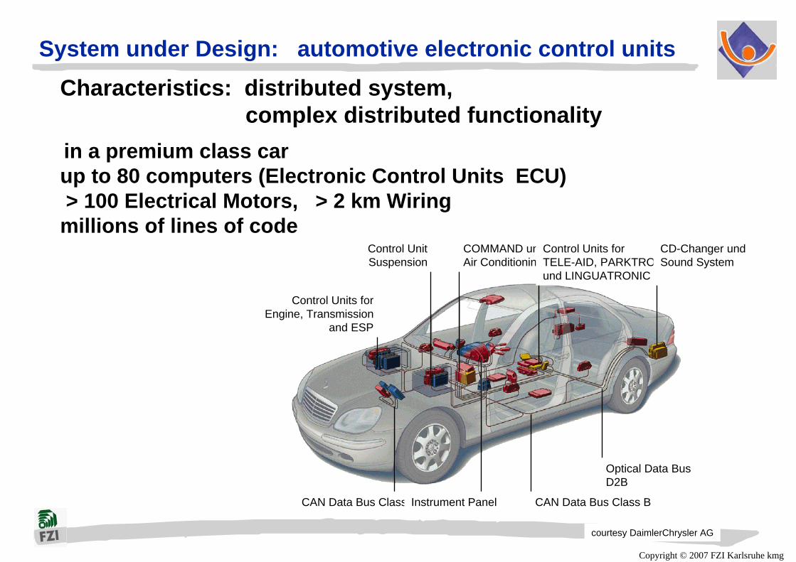
System under Design: automotive electronic control unitsCharacteristics: distributed system,
complex distributed functionalityin a premium class carup to 80 computers (Electronic Control Units ECU)> 100 Electrical Motors, > 2 km Wiringmillions of lines of code
courtesy DaimlerChrysler AG
Control UnitSuspension
Control Units forEngine, Transmission
and ESP
COMMAND undAir Conditioning
Control Units forTELE-AID, PARKTRONICund LINGUATRONIC
CD-Changer undSound System
Optical Data BusD2B
CAN Data Bus Class BCAN Data Bus Class CInstrument Panel

Copyright © 2007 FZI Karlsruhe kmg
Mechatronic Example:HydraulicBrake System
Benz
Characteristics: distributed, mechatronic
ECU’s are part ofmechatronic systems formeasurement and control
Softwareis part of ECU

Copyright © 2007 FZI Karlsruhe kmg
Characteristics: distributed, mechatronic, hard real time
Hard Real Time Constraints
Example:Airbag ControlUnit

Copyright © 2007 FZI Karlsruhe kmgBenz
General structure of an ECU
MicrocontrollerDSP
Real Time Operating System
Communication with other Systems
Communication with other Systems
Pow
er S
uppl
y
Syst
em C
ontr
ol
optical
mechanical
thermal
electrical
magnetic
Act
uato
rsSe
nsor
s
Rea
l env
ironm
ent
Analogsignal
processing
Analogsignal
processing
DigitalSignal
Processing
DigitalSignal
Processing
Spec
ial i
nter
face
s
Power electronicsPower electronics

Copyright © 2007 FZI Karlsruhe kmg
Complex Communication (e.g. Audi A8)
Courtesy Volkswagen/Audi
4 application domains for ECUs:
Power train: mainly closed loop control functionsChassis control: mainly closed loop control functionsBody electronics: mainly reactive, event driven functionsInfotainment: mainly reactive, event driven functions
software intensive >>100k LOC
Copyright © 2007 FZI Karlsruhe kmg
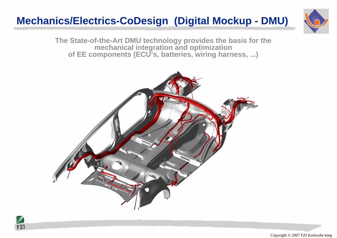
Mechanics/Electrics-CoDesign (Digital Mockup - DMU)
The State-of-the-Art DMU technology provides the basis for the mechanical integration and optimization
of EE components (ECU’s, batteries, wiring harness, ...)
Copyright © 2007 FZI Karlsruhe kmg
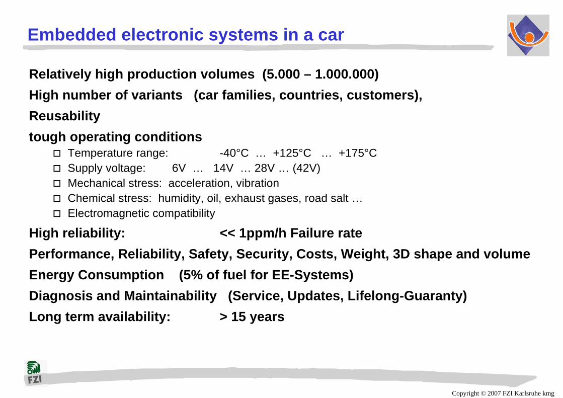
Embedded electronic systems in a car
Relatively high production volumes (5.000 – 1.000.000)High number of variants (car families, countries, customers), Reusabilitytough operating conditions
Temperature range: -40°C … +125°C … +175°CSupply voltage: 6V … 14V … 28V … (42V)Mechanical stress: acceleration, vibrationChemical stress: humidity, oil, exhaust gases, road salt …Electromagnetic compatibility
High reliability: << 1ppm/h Failure ratePerformance, Reliability, Safety, Security, Costs, Weight, 3D shape and volumeEnergy Consumption (5% of fuel for EE-Systems)Diagnosis and Maintainability (Service, Updates, Lifelong-Guaranty)Long term availability: > 15 years

Copyright © 2007 FZI Karlsruhe kmg
Automotive Electric/Electronic Systems
More than 30% of production costsfor a passenger car
is for electric/electronic systems(up to 40% by 2010)
90 % of all innovations arebased on electronic systems
Software part is increasing rapidly

Copyright © 2007 FZI Karlsruhe kmg
Automotive ECU: complex Design Process
Complex, distributed mechatronic systemwith hard real time constraints
Design process shared between car manufacturer (OEM)and several tier 1 suppliers
OEM defines features, sets up requirement specification Supplier refines requirements specification, designs and delivers
optimized and verified subsystem (complete mechatronic system including sensors, actuators, ECU hardware and software)
OEM tests subsystem, integrates with other subsystemsand verifies and validates overall system
Complex design process

Copyright © 2007 FZI Karlsruhe kmg
Hierarchical Organization of Design Processes
SystemSpecification
SystemSimulation
Development ofHW /SW
Specification
PrototypeDevelopment
CalibrationVehicle
Validation
Release toManufacturing Manufacturing
FunctionalTest Service
HWDesign
HWSimulation
PrototypeAssembly
DesignVerification
Release toManufacturing Manufacturing
FunctionalTest
AutocodePrototyping
SWCoding
Static andDynamic Test
Development ofControl Algorithms
and OnboardDiagnostics
Car programrequirements
Emission lawsStrategic
requirements
10s + 10s+5+-
+
Specification and Design Manufacturing Service
MechatronicVehicleSystem
ElectronicControlUnit (HW)
EmbeddedRealtimeSoftware
void main()
{...}
void initialization()
{...}
static void control (input, states, output)
{...}
multipleinterleaving design processes
Concurrent Engineeringdistributed between OEM and Tier 1 Suppliers

Copyright © 2007 FZI Karlsruhe kmg
Complex Manufacturer Supplier Relationship
Car manufacturer controls system design and system integrationdifferent „Business-Models“ for software and hardware development
by tier 1 suppliers
Require-mentsSpecifi-cation
FunctionAnalysis,Design & Modelling
LogicalSystemIntegration
ECUDevelopm.Integration
PhysicalSystemIntegration
SW / HWSupplier
Software Supplier
Car Manufact.
Hardware Supplier
SW / HWSupplier
Car Manufact.
Car Manufact.
Car Manufact.
Concurrent Engineeringdistributed between OEM and supplier
Quality Assurance requirescomprehensive life cycle model (V-Model)
strictly controlled design methodologysupporting computer aided design tools

Copyright © 2007 FZI Karlsruhe kmg
Design Methodology - a Lifecycle Process Model
Lifecycle Process Model
V-ModelDevelopment Standard for IT-Systems
of the Federal Republic of Germany
http://www.v-modell.iabg.de

Copyright © 2007 FZI Karlsruhe kmg
V Model: 4 sub modelsFour sub models are closely linked to one another and influence each otherconcerning the exchange of products/results.
ConfigurationStructure
Planning andControlling the Project
PM
SD
QA CM
Plan Data Actual Data SDE
SDE
QAResult
ActualData
QA Requirement
Product
ProductDevelopment
Specification ofQA
Requirements
ProductAssessment
Administration ofProducts/
Rights
Planning ProductStructure
PlanData
SDE SDEPlanData
PlanData
ActualData
ActualData
Product
Rights
Setting up Prerequisitesand Availability of Software
Development Environment (SDE)
Cooperation of Submodels
PM plans, controls and informs the SD, QA and CM sub models.
QA specifies quality requirements, test cases and criteria, and examines the products and the compliance with the standards
CM administrates the products generated
SD develops the system or the software.
Copyright © 2007 FZI Karlsruhe kmg
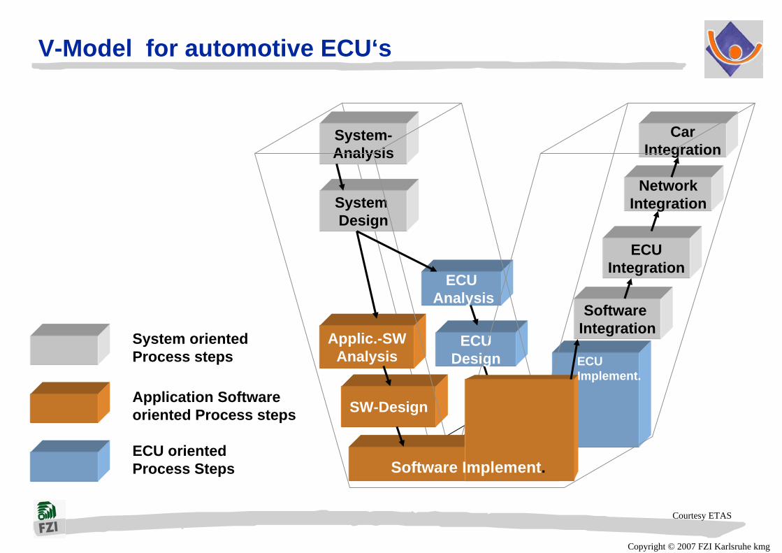
System oriented Process steps
Application Softwareoriented Process steps
ECU orientedProcess Steps
SW-Design
Applic.-SWAnalysis
System Design
ECUDesign
System-Analysis
CarIntegration
NetworkIntegration
ECUAnalysis
ECU Implement.
ECUIntegration
Software Integration
Software Implement.
V-Model for automotive ECU‘s
Courtesy ETAS
Copyright © 2007 FZI Karlsruhe kmg
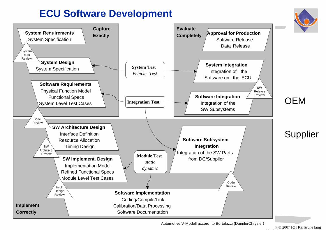
ECU Software Development
Automotive V-Modell accord. to Bortolazzi (DaimlerChrysler)
Software ImplementationCoding/Compile/Link
Calibration/Data ProcessingSoftware Documentation
System TestVehicle Test
Integration Test
Module Teststatic
dynamic
SW Implement. DesignImplementation Model
Refined Functional SpecsModule Level Test Cases
SW Architecture DesignInterface Definition
Resource AllocationTiming Design
Software RequirementsPhysical Function Model
Functional SpecsSystem Level Test Cases
System DesignSystem Specification
System RequirementsSystem Specification
SystemRequ
Review
Spec.Review
SWArchitect. Review
Impl.DesignReview
Software SubsystemIntegration
Integration of the SW Partsfrom DC/Supplier
Software IntegrationIntegration of theSW Subsystems
System IntegrationIntegration of the
Software on the ECU
Approval for ProductionSoftware Release
Data Release
SWReleaseReview
ImplementCorrectly
CaptureExactly
EvaluateCompletely
CodeReview
OEM
Supplier

Copyright © 2007 FZI Karlsruhe kmg
System specification as basis for cooperative design process
Costumer-Order
SystemSpecification
SystemDesign
ModuleDesign
Implementation SWRealization HW
ModuleTest HW/SW
SubsystemTest HW/SW
System-Integration, Test, Application
Deliveryto costumer
expensive iterationcycles due to- incomplete- wrong- ambiguous- inconsistent
system specificationFormal Specifications, executable,
Model Based Design

Copyright © 2007 FZI Karlsruhe kmg
prime error source: requirements specification
More than 40% of system faults originate from errorsduring requirements analysis and management , costly when late repair...
28%
5% 5% 6% 7%
2%
42%
6%
RequirementsErrors
Logic Design
Document-ation
Human
Environment InterfaceData Other
Sheldon, et alIEEE Software, July 1992
Percentage of errors classified by problem type on a large IT project

Copyright © 2007 FZI Karlsruhe kmg
System IntegrationCalibration, ApplicationTransition to Utilization
Typical Design Flow
Rapid PrototypingHardware PlatformCode Generation
Real Time Operating Systemconfigurable Interfaces
HW/SW-ImplementationIntegration
W-Modules, Data Dictionary, SW-CompHW-Component, HW-ModuleHW-Realization Documents
&
&
&&
Detailed HW/SW-DesignSW-Design, Data Dictionary
HW-DrawingsHW-Analysis Report
PROCESS (schlupf, state)BEGIN
CASE state ISWHEN freilauf =>
IF schlupf > 0 THENnext_state <=
bremsen;ELSE
HW/SW-Requirements AnalysisPreliminary HW/SW-Design
HW-Architecture, SW-ArchitectureInterface Description
FreiFrei
BremsenBremsen
Rad 1 Rad 1
ASR KontrolleASR Kontrolle
Rad 1
Bremsen
Frei
Rad 2
Bremsen
Frei
Idea System-Analysisexecutable SpecsSystem Design
model basedCustomer Requirements Technical RequirementsReal Time Requirements
System ArchitectureSimulation, Verification

Copyright © 2007 FZI Karlsruhe kmg
ECU development for passenger cars: 3 Prototypes
concept-orientedRapid Prototyping(A-Muster)
architecture-orientedRapid Prototyping(B-Muster)
Implementation-orientedRapid Prototyping(C-Muster)
Requirements-Analysis
Life Cycle-Analysis
SystemSpecification
SystemDesign
SubsystemDesign
ModuleDesign
System-Implementation
ModuleTest
SubsystemTest
SystemTest
SystemDelivery
Prototype
Prototype
Prototype

Copyright © 2007 FZI Karlsruhe kmg
Verification and Validation
Copyright © 2007 FZI Karlsruhe kmg
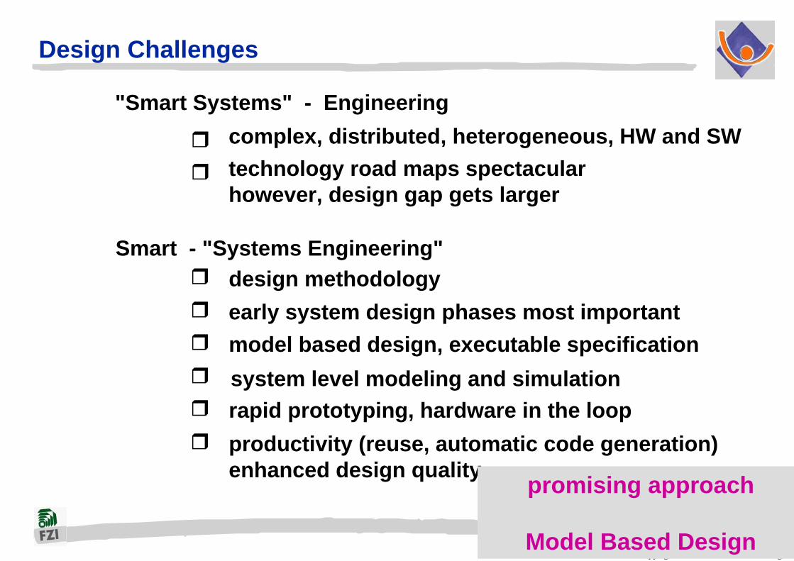
Design Challenges
"Smart Systems" - Engineering complex, distributed, heterogeneous, HW and SWtechnology road maps spectacularhowever, design gap gets larger
Smart - "Systems Engineering" design methodology early system design phases most important model based design, executable specification
rapid prototyping, hardware in the loopproductivity (reuse, automatic code generation)enhanced design quality
system level modeling and simulation
promising approach
Model Based Design

Copyright © 2007 FZI Karlsruhe kmg
Model Based Design - graphical descriptions preferred
Closed Loop Control
Reactive Systems
Performance Analysis

Copyright © 2007 FZI Karlsruhe kmg
Model Based Design:
SystemEnvironment-
Model
Stimuli-Model System-
Model(MUT)
Analysis-model
(expected responses)
Models for Executable Specification and Analysis (Simulation)

Copyright © 2007 FZI Karlsruhe kmg
Modeling
Modeling for complete system including system environment(ECU, car, driver, road, weather conditions)
Domain specific models for Subsystems and Components(closed loop control, reactive systems, software intensive systems)
Different abstraction levels, Parameter variation and boundaries(functional and non-functional data for early design space exploration)
Use of characterized libraries (reuse, variant design)
Macro modeling
Model verification through extensive testing
Model characterization
Model documentation
Meta modeling

Copyright © 2007 FZI Karlsruhe kmg
Challenges for Modeling
Domain Specific Modeling LanguagesModel SynthesisModel ValidationModel TransformationExecutable ModelsAutomatic Generation of Product Artefacts
Meta-ModelingTools on Meta-Model-LevelIntegration of Domain Specific Toolson Meta-Level
Generic Modeling-Platforms

Copyright © 2007 FZI Karlsruhe kmg
Meta-model based design (Sztipanovits, Karsai: Vanderbilt University)

Copyright © 2007 FZI Karlsruhe kmg
Modeling for heterogeneous electronic embedded systems
ArchitectureModelling with UML
Rhapsody in C++ (i-Logix) Statemate (i-Logix)Stateflow (The MathWorks)ASCET (ETAS)
Event drivenModelling with state charts
Buffer::Buffer SocketListItem1 *
outputBuffer 1
ProcessorBuffer
BatchController
SocketListItem
inputBuffer
1 *
1
Idle Sending Waiting_For_Repeat
Waiting_For_Ack
evRepeat[myCondition]
evBusyevAck /Action1()
Idle Sending Waiting_For_Repeat
Waiting_For_Ack evBusy/Action1()
ASCET (ETAS) MATLAB/Simulink (The MathWorks)MATRIXx (National Instruments)
Signal flow orientedModelling with block diagrams
Real-time Studio (ARTiSAN)Rhapsody in C++ (i-Logix)Rose (Rational Software, IBM)Together (Borland)Poseidon (Gentleware)MagicDraw (NoMagic)Ameos (Aonix)TAU2 (Telelogic)
Heterogeneous modeling requires integration platforme.g. ETAS Integrio, Vector DaVinci

Copyright © 2007 FZI Karlsruhe kmg
Compiler / Linker / Make
Matlab/WrapperGenerator
JAVA
C
Matlab/WrapperGenerator
JAVA
MatlabAutomation
JAVA
MatlabEmbedded Coder
DCOM
Target platforms (RTOS)
ITIV/FZI Tool integration platform (model transformation)
GeneralStore CASE-Tool Integration Platform
TemplateUML Coder
XMI
C++
...generator
other commercial
code generators
XMI2XX
C/C
++
CG-Adaptor
Rhapsody in MicroC
automation
JAVA
MicroC
XMI
C
JAVA
Target-MonitoringModel Debugging
Test
Matlab/WrapperGenerator
JAVA
Matlab/WrapperGenerator
JAVA
Matlab WrapperGenerator
JAVA
Statemate WrapperGenerator
JAVA
Model DataMySQL, ORACLE
SQL
MATLABSimulink
MDL
MATLABSimulinkStateflow
MDL
ASCET
XMI XMI 1.0, XMI 1.1, XMI 1.2
Rhapsody
Poseidon
MagicDraw
Together
Rose
ARTiSAN
AONIX
Statemate
new challenge

Copyright © 2007 FZI Karlsruhe kmg
Meta-Modeling 4 Abstraction Layers (OMG standard)
real
abstract M3 layer MOF
M2 layer UML 1.5 UML 2.0 MATLAB Simulink
Statechart(D. Harel)
M1 layer UMLModel
Statechart Model
Simulink Model
M0 layer Objects Data Source code
Real artefacts
Copyright © 2007 FZI Karlsruhe kmg
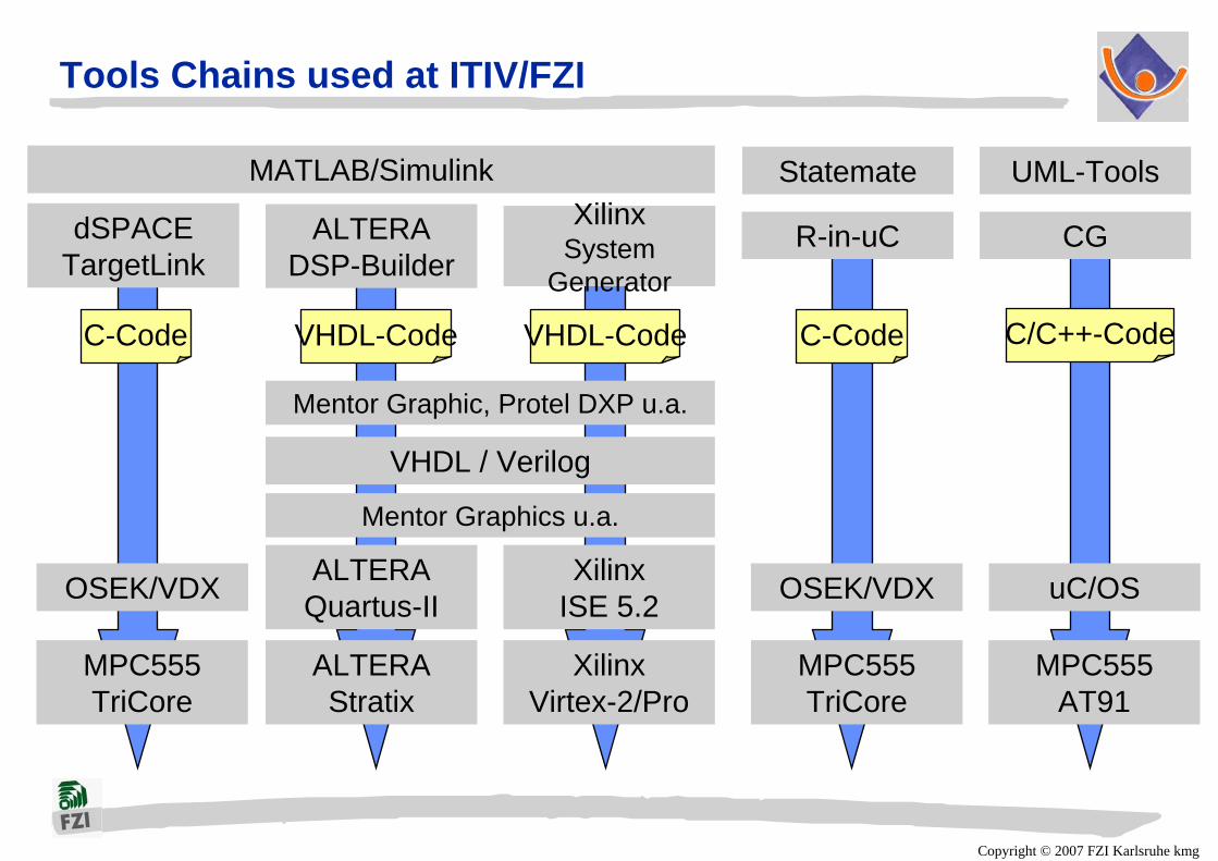
Tools Chains used at ITIV/FZI
VHDL / Verilog
Mentor Graphics u.a.
ALTERA Quartus-II
XilinxISE 5.2
ALTERAStratix
XilinxVirtex-2/Pro
Mentor Graphic, Protel DXP u.a.
MATLAB/Simulink
ALTERADSP-Builder
XilinxSystem
Generator
dSPACETargetLink
MPC555TriCore
OSEK/VDX
Statemate
R-in-uC
MPC555TriCore
OSEK/VDX
UML-Tools
CG
MPC555AT91
uC/OS
C-Code VHDL-Code VHDL-Code C-Code C/C++-Code

Copyright © 2007 FZI Karlsruhe kmg
ITIV/FZI Tool Chains (Automotive) Verification Support
MATLAB/Simulink
dSPACETargetLink
MPC555TriCore
OSEK/VDX
Statemate
R-in-uC
MPC555TriCore
OSEK/VDX
C-Code C-Code
ETAS ASCET-SD
TIP
MPC555TriCore
OSEK/VDX
C-Code
POLYSPACE C-Verifier (MISRA-C, DO-178B)
Copyright © 2007 FZI Karlsruhe kmg
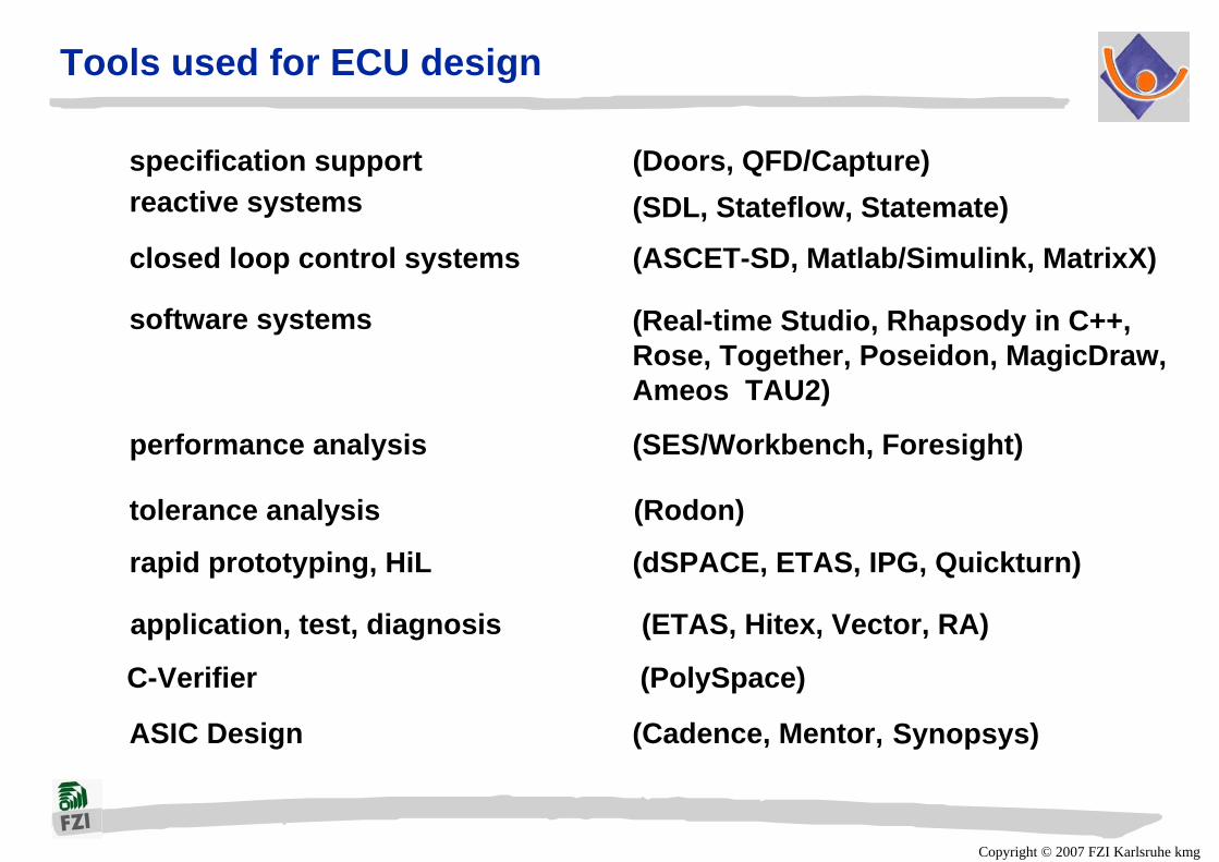
Tools used for ECU design
specification support (Doors, QFD/Capture) reactive systems (SDL, Stateflow, Statemate)
closed loop control systems (ASCET-SD, Matlab/Simulink, MatrixX)
software systems (Real-time Studio, Rhapsody in C++,Rose, Together, Poseidon, MagicDraw,Ameos TAU2)
performance analysis (SES/Workbench, Foresight)
ASIC Design (Cadence, Mentor, Synopsys)
rapid prototyping, HiL (dSPACE, ETAS, IPG, Quickturn)
tolerance analysis (Rodon)
application, test, diagnosis (ETAS, Hitex, Vector, RA)
C-Verifier (PolySpace)
Copyright © 2007 FZI Karlsruhe kmg
Design Challenges: Automotive ECU
Complex, distributed mechatronic systemwith hard real time constraints
Design process shared between car manufacturer (OEM)and several tier 1 suppliers
OEM defines features, creates specification model Supplier develops specification model into
implementation model, does analysis and design,verification and validation, builds and tests,finally delivers optimized subsystem to OEM(Sensor, Actuator, ECU hardware and software)
However,Still increasing complexity (more comfort and safety functions
coming)

Copyright © 2007 FZI Karlsruhe kmg
EUCAR: Active Safety – System Integration
ACCS&Getc
Lanedeparturewarning
Brakeassistant
Emergencybrakingsystem,Collision
avoidance
Pedestrianairbag
Crashseverity sensingfor ignition levelsand belt tension
Emergency/MaydaySystemsA
DA
SE
Basic Vehicle Safety Occupant Protection
Collision Avoidance
Pre-Crash PhaseRescue
NormalDriving
WarningSystems
AssistanceSystems
AutomaticSafety
Systems
SafetySystems
for minimalcrash
SafetySystemssoft level
SafetySystems
hard level SafetySystems
after Crash
1.2.
3. 4.
5.
6.
7.
Passive Safety
Active SafetyCrash Probability
Leve
l of c
ritic
al s
afet
y si
tuat
ions
Holistic Safety Approach
Crash
Challenge: new safety functions

Copyright © 2007 FZI Karlsruhe kmg
Future systems
Copyright © 2007 FZI Karlsruhe kmg
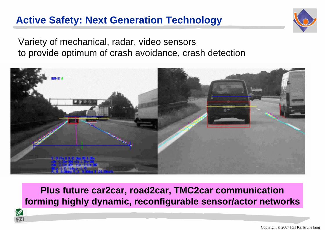
Active Safety: Next Generation Technology
Variety of mechanical, radar, video sensorsto provide optimum of crash avoidance, crash detection
Plus future car2car, road2car, TMC2car communicationforming highly dynamic, reconfigurable sensor/actor networks

Copyright © 2007 FZI Karlsruhe kmg
Distributed ECU’s in cars - design challenges
Still increasing complexity (more comfort and safety functions coming)
number of ECU’s must not increase, should decrease!less, but more powerful HW platforms (8, 16, 32-bit µC)eventually new, more flexible architectures(e.g. dynamically reconfigurable?!)
Copyright © 2007 FZI Karlsruhe kmg
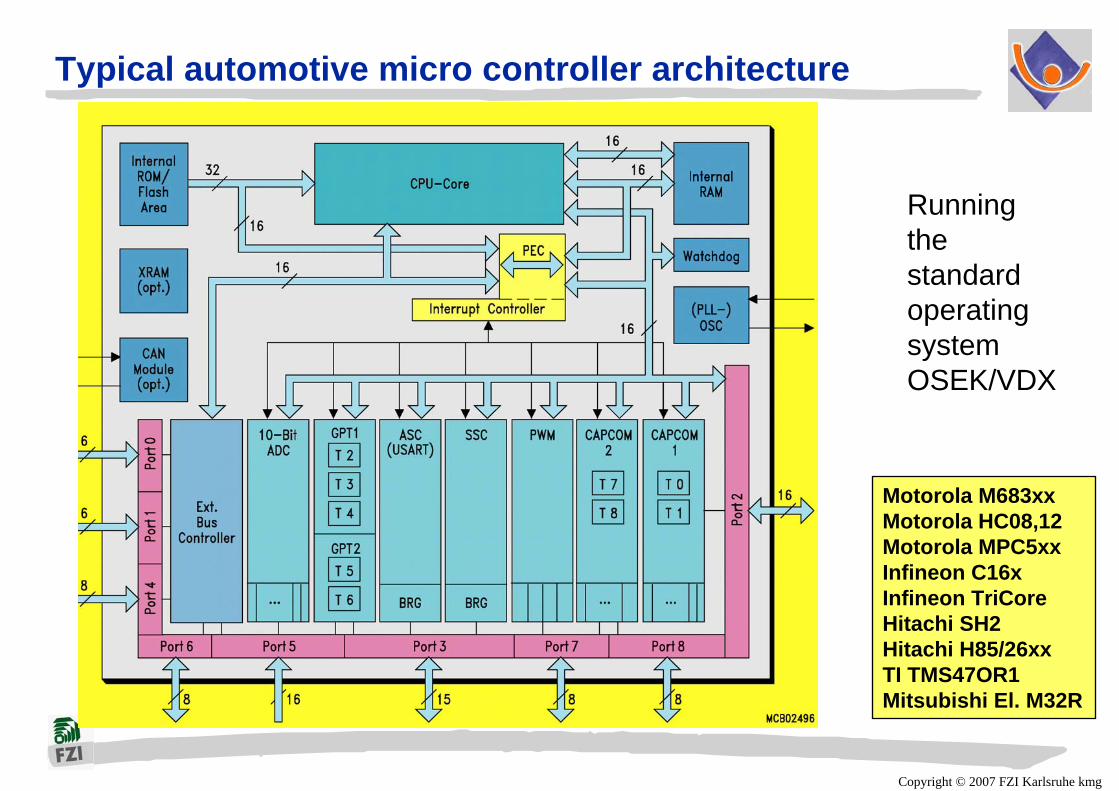
Typical automotive micro controller architecture
Running thestandard operatingsystemOSEK/VDX
Motorola M683xxMotorola HC08,12Motorola MPC5xxInfineon C16xInfineon TriCoreHitachi SH2Hitachi H85/26xxTI TMS47OR1Mitsubishi El. M32R
Copyright © 2007 FZI Karlsruhe kmg
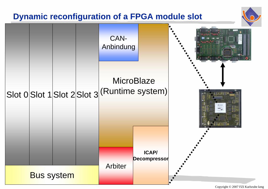
Dynamic reconfiguration of a FPGA module slot
Bus systemArbiter
ICAP/Decompressor
CAN-Anbindung
Slot 3Slot 2Slot 1Slot 0MicroBlaze
(Runtime system)

Copyright © 2007 FZI Karlsruhe kmg
Dynamic reconfiguration of a FPGA module slot
Bus systemArbiter
ICAP/Decompressor
CAN-Anbindung
Slot 3Slot 2Slot 1Slot 0MicroBlaze
(Runtime system)

Copyright © 2007 FZI Karlsruhe kmg
Distributed ECU’s in cars - design challenges
Still increasing complexity (more comfort and safety functions coming)
number of ECU’s must not increase, should decrease!less, but more powerful HW platforms (8, 16, 32-bit µC)eventually new, more flexible architectures(e.g. dynamically reconfigurable?!)
Given new hardware platforms requires redistribution (mapping) of software onto fewer hardware platforms
Easy redistribution only possible with open system architecture (standardized communication, standardized RTOS)
Copyright © 2007 FZI Karlsruhe kmg
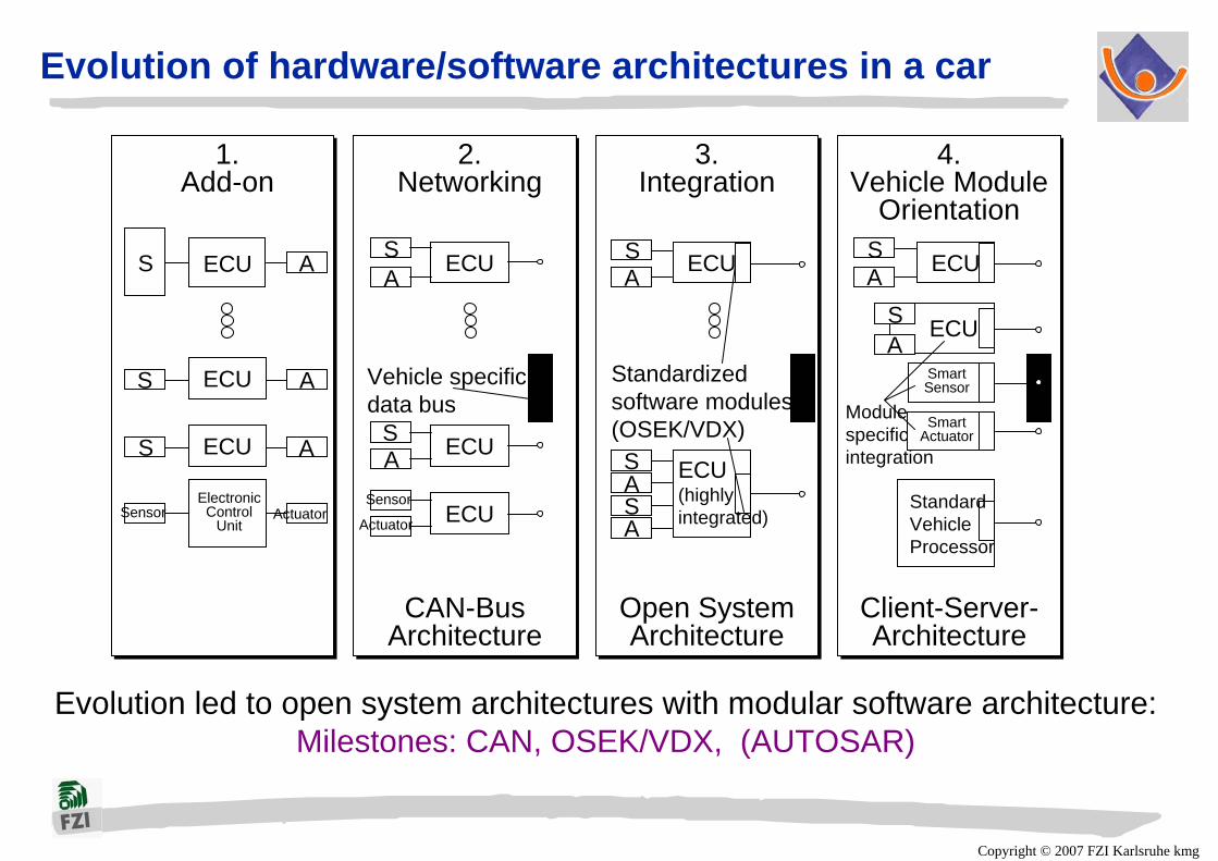
Evolution of hardware/software architectures in a car
Evolution led to open system architectures with modular software architecture:Milestones: CAN, OSEK/VDX, (AUTOSAR)
1.Add-on
2.Networking
3.Integration
4.Vehicle Module
Orientation
CAN-BusArchitecture
Open System Architecture
Client-Server-Architecture
ECU
ECU
ECU
ECU
ECU
ECU ECUS
S
S
Sensor ActuatorElectronic
ControlUnit
A
A
A
SA
SA
Sensor
Actuator
Vehicle specific data bus
SA
S
SA
A
Standardized software modules (OSEK/VDX)
ECU
ECU
SA
AS
Smart Sensor
Smart Actuator
ECU(highlyintegrated)
StandardVehicleProcessor
Modulespecificintegration
Copyright © 2007 FZI Karlsruhe kmg
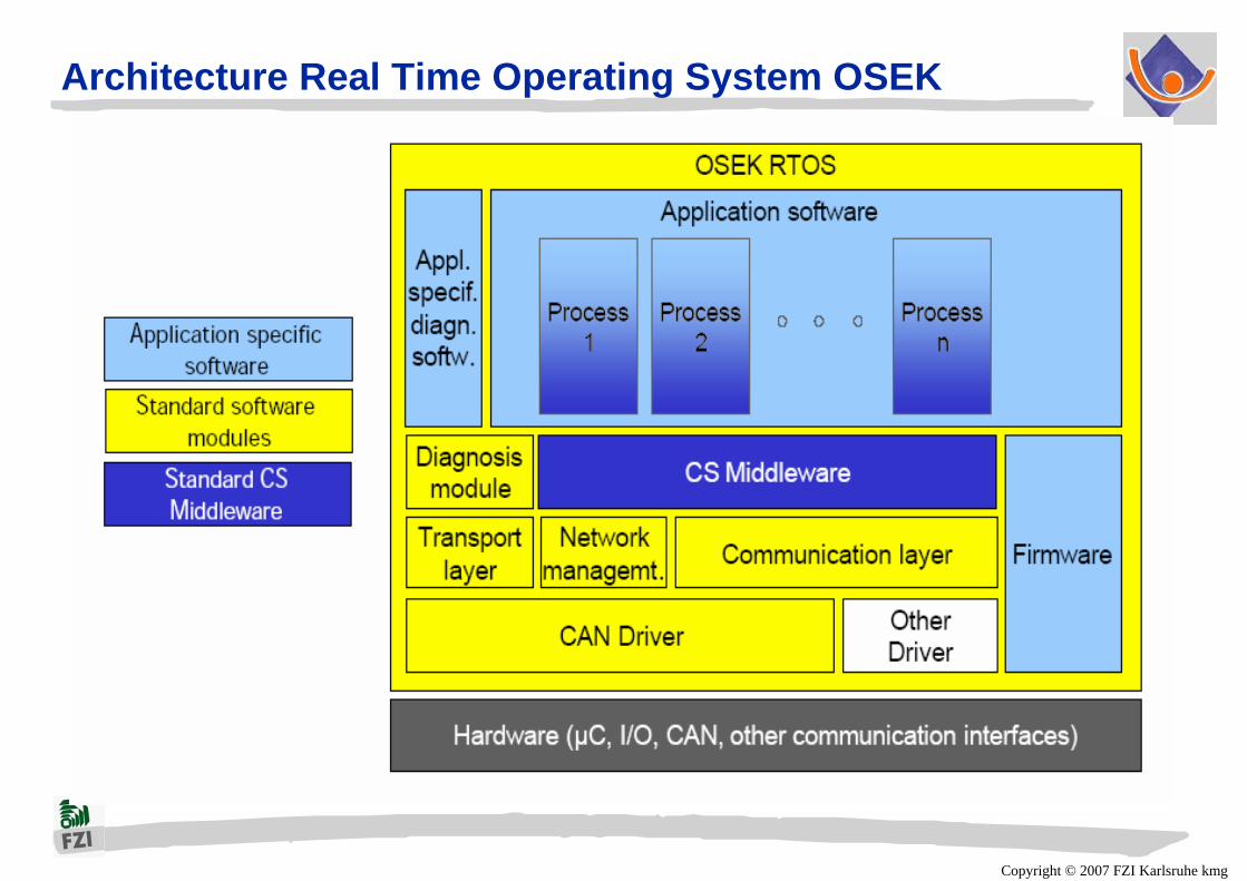
Architecture Real Time Operating System OSEK
Copyright © 2007 FZI Karlsruhe kmg
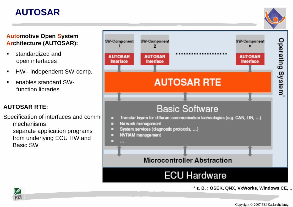
AUTOSAR
AUTOSAR RTE:Specification of interfaces and communication
mechanismsseparate application programsfrom underlying ECU HW andBasic SW
Automotive Open SystemArchitecture (AUTOSAR):
standardized andopen interfaces
HW– independent SW-comp.
enables standard SW-function libraries
* z. B. : OSEK, QNX, VxWorks, Windows CE, …
Copyright © 2007 FZI Karlsruhe kmg
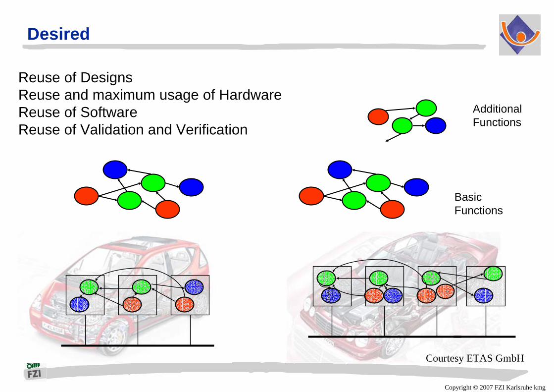
Desired
BasicFunctions
AdditionalFunctions
Reuse of DesignsReuse and maximum usage of HardwareReuse of SoftwareReuse of Validation and Verification
Courtesy ETAS GmbH

Copyright © 2007 FZI Karlsruhe kmg
Goal (AUTOSAR)
Vehicle B
Hardware B
Goal:
Automatic Code Generation
Hardware A
Mapping B
Functional Integration
Vehicle A
Seat Adjustment A
Seat Adjustment B
Lighting
Seat Heating A
Seat Heating B
Air Conditioning
Function Library
ECU Library
Mapping A Quality AssuredSoftware Function Library
Quality AssuredHardware PlatformsLibrary

Copyright © 2007 FZI Karlsruhe kmg
Challenge
AlgorithmIntegration
C, C++Matlab
SDL, SPWCossap
FunctionalNetwork
Does thefunctionally
integrateddesign work
ExecutableFunctional
Specification unlim
ited
mapping
ArchitecturePerformance
CPU, DSPBus, I/O
Memory, HWSW, RTOS
UnambiguousStructure
Perf
orm
ance Are
Partitioning &Performance Sufficient?
ExecutablePerformanceSpecification
detailed designAlberto Sangiovanni Vincentelli

Copyright © 2007 FZI Karlsruhe kmg
Another Challenge: Upcoming X-by-Wire Systems
Delayed for 4 to 5 years
First driver assistance systems overruling driver currently being introduced (truck emergency brake system)
EN 61508 norm for safety critical electronic control systems not yet finally adapted for car industry.
System Redundancy required:HW redundancy: sensors, actuators, ECU’s, busses (Flexray) doubledInformation redundancy: error detection/correction codes usedTime redundancy: all messages send twice on each busSoftware Redundancy: two version programming?!
Certification required as in aerospace industry?

Copyright © 2007 FZI Karlsruhe kmg
Aircraft-Level FHA
PSSAs
SSAs
System-LevelFHA Sections
Aircraft-LevelRequirement
Allocation AircraftFunction to Systems
Development ofSystem Architecture
Allocation ofRequirementsto HW & SW
SystemImplementation
Safety Assessment Process System Development Process
Certification
Aircraft Functions
Failure Conditions, Effects, Class., Safety Requ.
System Architecture
Item Requirements
ResultsPhysical System
CCAs
FailureConditions& Effects
SeparationRequir.
System Functions
Failure Cond., Effects, Class., Safety ObjectivesArchitectural Requirements
ImplementationSeparation& Verification
Safety critical aerospace ECU development
Stefan Benz
Development Standard SAE ARP 4754
Aircraft-Level FHA
PSSAs
SSAs
System-LevelFHA Sections
Aircraft-LevelRequirement
Allocation AircraftFunction to Systems
Development ofSystem Architecture
Allocation ofRequirementsto HW & SW
SystemImplementation
Safety Assessment Process System Development Process
Certification
Aircraft Functions
Failure Conditions, Effects, Class., Safety Requ.
System Architecture
Item Requirements
ResultsPhysical System
CCAs
FailureConditions& Effects
SeparationRequir.
System Functions
Failure Cond., Effects, Class., Safety ObjectivesArchitectural Requirements
ImplementationSeparation& Verification

Copyright © 2007 FZI Karlsruhe kmg
Distributed ECU’s in cars - design challenges
Still increasing complexity (more comfort and safety functions coming)
Today’s E/E architecture in a car is characterized by an assembly of (too) many locally optimized subsystems
Only OEM can go for global optimum
new system level design exploration tools are required

Copyright © 2007 FZI Karlsruhe kmg
EE-Architecture alternative solutions

Copyright © 2007 FZI Karlsruhe kmg
Tools to support architecture based development process
Courtesy J.Bortolazzi, DC
Copyright © 2007 FZI Karlsruhe kmg
Requirements for new system level tools
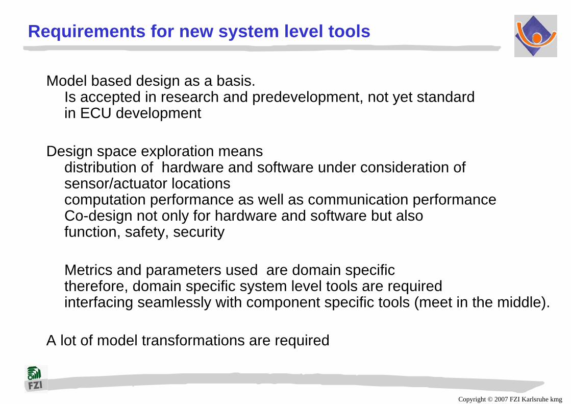
Model based design as a basis.Is accepted in research and predevelopment, not yet standardin ECU development
Design space exploration meansdistribution of hardware and software under consideration ofsensor/actuator locationscomputation performance as well as communication performanceCo-design not only for hardware and software but alsofunction, safety, security
Metrics and parameters used are domain specifictherefore, domain specific system level tools are requiredinterfacing seamlessly with component specific tools (meet in the middle).
A lot of model transformations are required

Copyright © 2007 FZI Karlsruhe kmg
Architecture Layers in Concept Development
Copyright © 2007 FZI Karlsruhe kmg
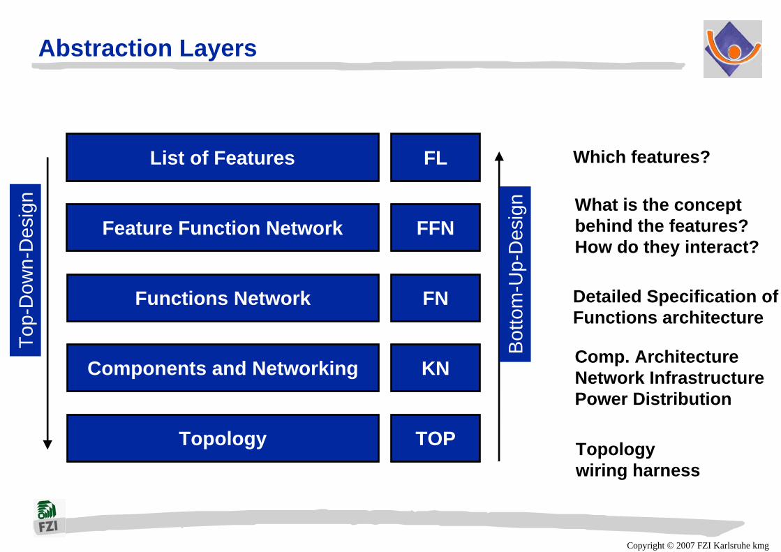
Abstraction Layers
Feature Function Network
List of Features
Functions Network
Components and Networking
Topology
FL
FFN
FN
KN
TOP
Top-
Dow
n-D
esig
n
Bot
tom
-Up-
Des
ign
Which features?
Detailed Specification of Functions architecture
Comp. ArchitectureNetwork InfrastructurePower Distribution
Topologywiring harness
What is the concept behind the features?How do they interact?

Copyright © 2007 FZI Karlsruhe kmg
Abstraction Layers
Typical domain specific views
Features
Functions
Components
Component locations and wiring
Design space explorationneeds domain specific metricsand parameters

Copyright © 2007 FZI Karlsruhe kmg
Abstraction layers of new EE-concept toolCustomer Requirements
Functions-Architecture
-Feature-Architecture
Features
Component-Network Architecture
(MAP)
Electronic
HW
SW
Feature-Function Type Builder
Requirem.
Electric
PhysicsGeometry
(MAP)
(MAP)
(MAP)
Feature-Function Network Edit.
Function Type BuilderFunction Network Editor
Signal Editor
Network Editor Component Editor
Power Distribution Editor Demand View
Cluster View
Physical Architecture
Topology Editor
Cable Harness
Copyright © 2007 FZI Karlsruhe kmg
60
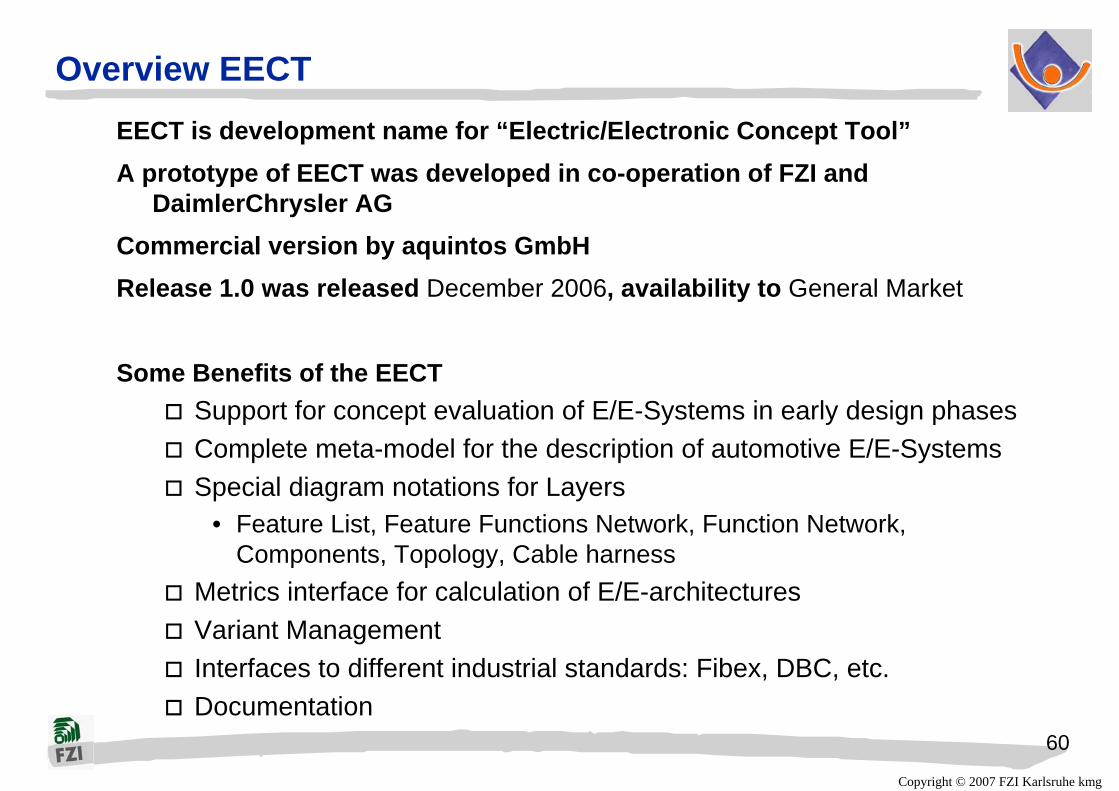
Overview EECT EECT is development name for “Electric/Electronic Concept Tool”A prototype of EECT was developed in co-operation of FZI and
DaimlerChrysler AGCommercial version by aquintos GmbHRelease 1.0 was released December 2006, availability to General Market
Some Benefits of the EECTSupport for concept evaluation of E/E-Systems in early design phasesComplete meta-model for the description of automotive E/E-Systems Special diagram notations for Layers
• Feature List, Feature Functions Network, Function Network, Components, Topology, Cable harness
Metrics interface for calculation of E/E-architecturesVariant ManagementInterfaces to different industrial standards: Fibex, DBC, etc. Documentation

Copyright © 2007 FZI Karlsruhe kmg
61
Evaluation / Calculation of the EE Concept
User defined metrics are supportedMetrics are implemented in PythonMetrics examples:
Count metrics• Weight• Volume• Space• Networking Complexity
CostsPower calculation

Copyright © 2007 FZI Karlsruhe kmg
62
Highlights of Model-to-Model-Technology
Optimized Transformator-Engine with Interfaces toETAS ASCET® (>= 5.1)The Mathworks MATLAB®/Simulink®/Stateflow® (R13 – R16)Fully integrated in PREEvision (for model consistency checks, variant propagation…)
Model-based Specification of Transformation RulesRule Set modeled with UMLMaintainability, ReadabilityAutomated Code Generation of theRule-Set, no manual design process behind
Purpose of M2M TransformationModel data migrationModel-RefactoringModel-OptimizationModel-Verification
M2ToS
Copyright © 2007 FZI Karlsruhe kmg
63
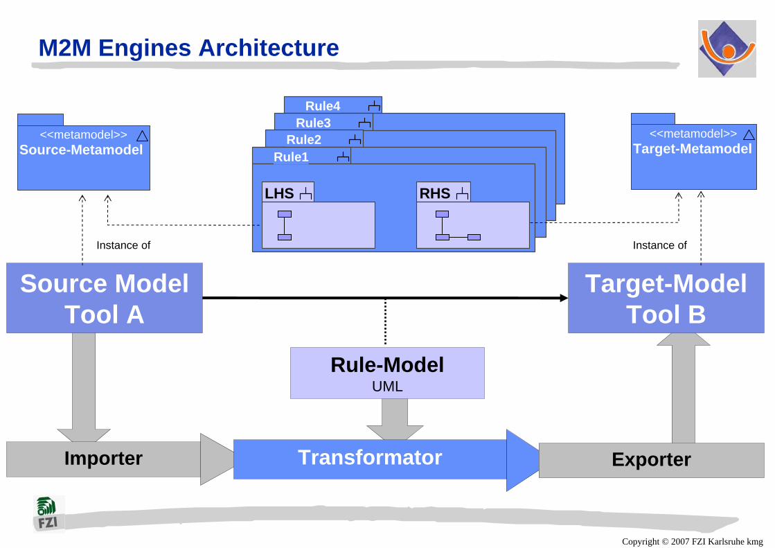
M2M Engines Architecture
Rule4Rule3
Rule2
Importer Transformator Exporter
Rule-ModelUML
Source ModelTool A
Target-ModelTool B
<<metamodel>>Source-Metamodel
<<metamodel>>Target-MetamodelRule1
LHS RHS
Instance of Instance of
Copyright © 2007 FZI Karlsruhe kmg
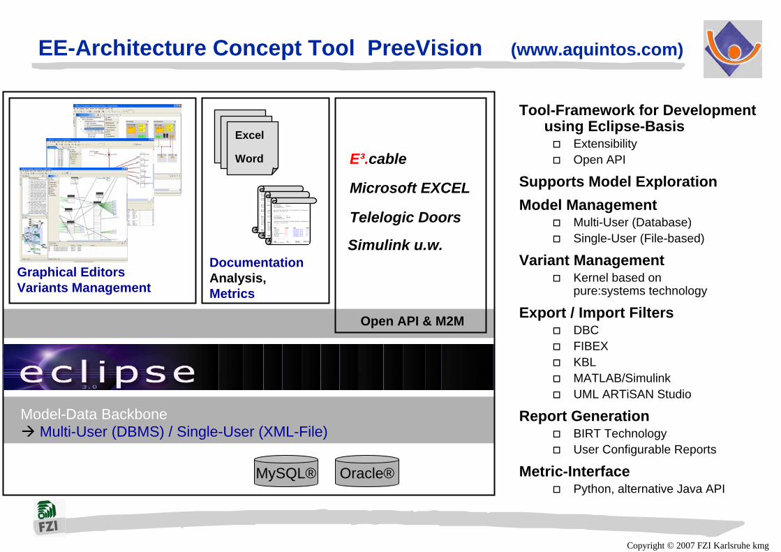
EE-Architecture Concept Tool PreeVision (www.aquintos.com)
Tool-Framework for Development using Eclipse-Basis
ExtensibilityOpen API
Supports Model ExplorationModel Management
Multi-User (Database)Single-User (File-based)
Variant ManagementKernel based onpure:systems technology
Export / Import FiltersDBC FIBEXKBLMATLAB/SimulinkUML ARTiSAN Studio
Report GenerationBIRT TechnologyUser Configurable Reports
Metric-InterfacePython, alternative Java API
Graphical EditorsVariants Management
MySQL® Oracle®
Model-Data Backbone
E³.cable
Microsoft EXCEL
Telelogic Doors
Open API & M2M
DocumentationAnalysis, Metrics
Excel
Word
Multi-User (DBMS) / Single-User (XML-File)
Simulink u.w.

Copyright © 2007 FZI Karlsruhe kmgBenz
System Level Tool Support
MicrocontrollerDSP
Real Time Operating System
Pow
er S
uppl
y
Syst
em C
ontr
ol
optical
mechanical
thermal
electrical
magnetic
Act
uato
rsSe
nsor
s
Rea
l env
ironm
ent
DigitalSignal
Processing
DigitalSignal
Processing
Power electronicsPower electronics
Communication with other Systems
Communication with other Systems
Analogsignal
processing
Analogsignal
processing
Spec
ial i
nter
face
s
Not seamless somehow satisfying support: standard hardware platforms, software, RTOS, Sensors und Actuators
Copyright © 2007 FZI Karlsruhe kmg
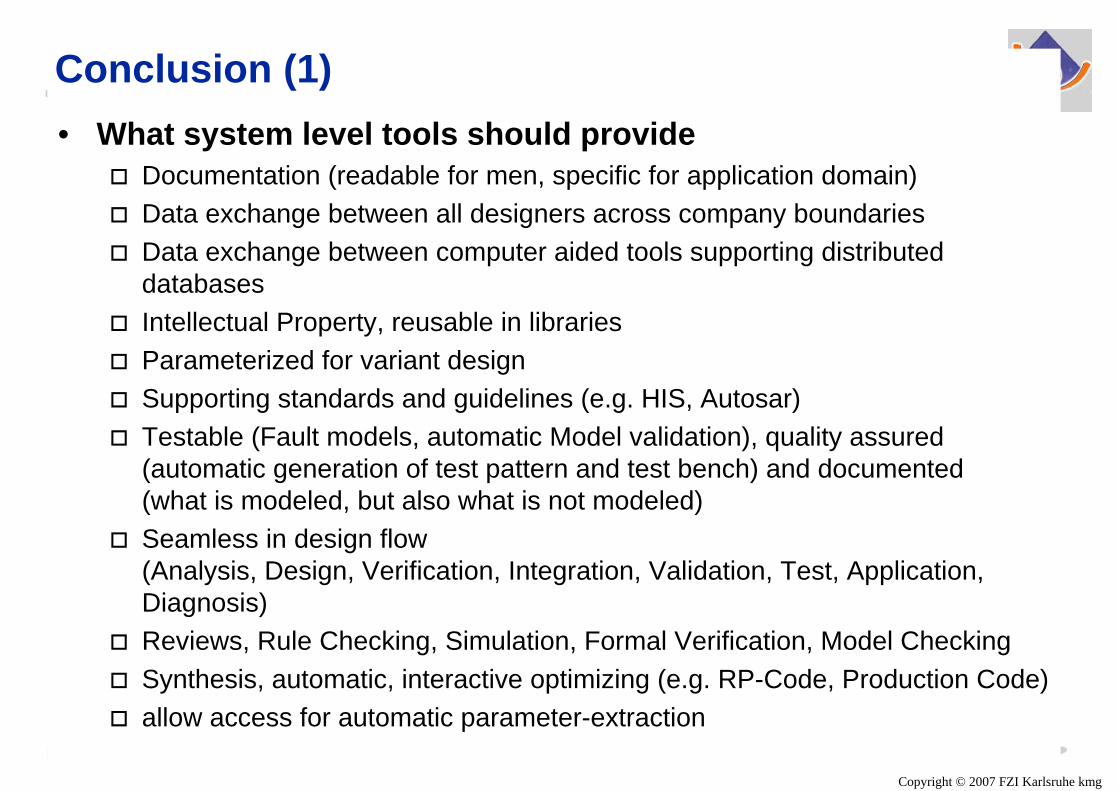
• What system level tools should provideDocumentation (readable for men, specific for application domain)Data exchange between all designers across company boundariesData exchange between computer aided tools supporting distributed databasesIntellectual Property, reusable in librariesParameterized for variant designSupporting standards and guidelines (e.g. HIS, Autosar)Testable (Fault models, automatic Model validation), quality assured(automatic generation of test pattern and test bench) and documented (what is modeled, but also what is not modeled)Seamless in design flow (Analysis, Design, Verification, Integration, Validation, Test, Application, Diagnosis)Reviews, Rule Checking, Simulation, Formal Verification, Model Checking Synthesis, automatic, interactive optimizing (e.g. RP-Code, Production Code)allow access for automatic parameter-extraction
Conclusion (1)

Copyright © 2007 FZI Karlsruhe kmg
Conclusion (2)Design studies show:• Model based methodologies and tools are well performing and promising • Seamless design flow only partially given (e.g. digital hardware, software).• Interfaces for Modeling, Simulation, Characterization mostly manual• hard problem for design of embedded systems
Cross sensitivity of Components (insufficient characterization)Safety, Security, Function-CodesignAccording modeling is really time and cost consumingMixed-Mode, Multi-Level-Simulation requiredFormal Verification und Validation not possible?!
• Non functional requirements• Time-, frequency- und parameter-domain
Module / System-Integration und –TestCross-sensitivities, EMC, Certification
Model based system design is possible,but there are many design and analysis steps still missing, especially in early design phases.

Copyright © 2007 FZI Karlsruhe kmg
Conclusion (3)Industrial design practice shows:• Challenges for the design of embedded systems
many modeling techniques from computer science not adequate:FSM, Hybrid Automata, LSC, MSC, Petri nets, process algebra, Statecharts, Temporal Logic, Timed Automata, Z …Is academic willing to prove their research results for real designs?!Seamless flow required with respect to industrial life cycle processes, therefore support of standard interfaces must be done also by academicsThere exist large libraries in different description methodologies that can‘t be neglectedThere exist standard RTOS (OSEK/VDX) and bus systemsThere exist tight cost boundariesNew algorithms and tools must be made commercially available Engineering constraints, adequate description methods according toDe-Facto-Standards (tools) must be obeyed: Matlab, ASCET, Statemate, Doors, Saber, VHDL, C, AssemblerFormal methods are not yet scaling for many real industrial problemsRequired from industry: availability of real requirements, constraints, cost numbers etc. for research
• Required: more close cooperation between system manufacturer, (tier 1) suppliers, EDA companies and academics
Copyright © 2007 FZI Karlsruhe kmg
Questions
Thank you very much for your attention
Contact:Klaus Müller-GlaserUniversität Karlsruhe, [email protected]