g1000 nxi system maintenance manual
TRANSCRIPT

190-00716-N1 November 2020 Revision 6
System Maintenance Manual
King Air 300 Series
Includes Instructions for Continued Airworthiness for STC SA01535WI-D

G1000 NXi System Maintenance Manual Page i King Air 300 Series Revision 6 190-00716-N1
© Copyright 2017 - 2020 Garmin Ltd. or its subsidiaries
All Rights Reserved Except as expressly provided herein, no part of this manual may be reproduced, copied, transmitted, disseminated, downloaded or stored in any storage medium, for any purpose without the express prior written consent of Garmin. Garmin hereby grants permission to download a single copy of this manual and of any revision to this manual onto a hard drive or other electronic storage medium to be viewed and to print one copy of this manual or of any revision hereto, provided that such electronic or printed copy of this manual or revision must contain the complete text of this copyright notice and provided further that any unauthorized commercial distribution of this manual or any revision hereto is strictly prohibited.
Garmin International, Inc. 1200 E. 151st Street
Olathe, KS 66062 USA Telephone: 913.397.8200
www.garmin.com
Garmin (Europe) Ltd. Liberty House, Bulls Copse Road
Hounsdown Business Park Southampton, SO40 9LR, UK Phone: +44 (0) 23 8052 4000
Fax: +44 (0) 23 8052 4004
Garmin AT, Inc. 2345 Turner Rd., SE
Salem, OR 97302 USA Telephone: 503.391.3411
RECORD OF REVISIONS
Revision Revision Date Description ECO #
1 1/30/2017 Initial Release --- 2 2/24/2017 Update for System Software v2286.02 1551683 7/16/2018 Update for System Software v2286.06 1758124 4/30/2019 Update for System Software v2286.07 188280
5 08/03/2020 Update for Model 300 Blackhawk PT6A-67A Engine configuration addition, engine indication check clarification, and minor typos
202315
6 11/18/2020 Updated for B300 heavy configuration 214084
DOCUMENT PAGINATION
Section Pagination Section Pagination Table of Contents i – x Section 5 142 - 231
Section 1 1 – 6 Section 6 232 - 261Section 2 7 – 45 Section 7 262 - 348Section 3 46 - 101 Section 8 349 - 381Section 4 102 - 141 Section 9 382 - 399

G1000 NXi System Maintenance Manual Page ii King Air 300 Series Revision 6 190-00716-N1
INFORMATION SUBJECT TO EXPORT CONTROL LAWS
This document may contain information which is subject to the Export Administration Regulations (“EAR”) issued by the United States Department of Commerce (15 CFR, Chapter VII Subchapter C) and which may not be exported, released or disclosed to foreign nationals inside or outside the United States without first obtaining an export license. The preceding statement is required to be included on any and all reproductions in whole or in part of this manual.
This product, its packaging, and its components contain chemicals known to the State of California to cause cancer, birth defects, or reproductive harm. This Notice is being provided in accordance with California's Proposition 65. If you have any questions or would like additional information, please refer to our web site at http://garmin.com/prop65. The GDU lens is coated with a special anti-reflective coating that is very sensitive to skin oils, waxes and abrasive cleaners. CLEANERS CONTAINING AMMONIA WILL HARM THE ANTI-REFLECTIVE COATING. It is very important to clean the lens using a clean, lint-free cloth and an eyeglass lens cleaner that is specified as safe for anti-reflective coatings. All G1000 screen shots used in this document are current at the time of publication. Screen shots are intended to provide visual reference only. All information depicted in screen shots, including software file names, versions and part numbers, is subject to change and may not be up to date.
CAUTION
WARNING
IMPORTANT

G1000 NXi System Maintenance Manual Page iii King Air 300 Series Revision 6 190-00716-N1
TABLE OF CONTENTS PARAGRAPH PAGE 1. INTRODUCTION ................................................................................................................. 1
1.1 Content, Scope, Purpose .............................................................................................. 1 1.2 Organization .................................................................................................................. 2 1.3 Definitions/Abbreviations ............................................................................................... 3 1.4 Units of Measure ........................................................................................................... 4 1.5 Publications ................................................................................................................... 4 1.6 Revision and Distribution ............................................................................................... 6
2. SYSTEM DESCRIPTION .................................................................................................... 7 2.1 Equipment Descriptions ................................................................................................ 7 2.2 G1000 Optional Interfaces ...........................................................................................23 2.3 Electrical Power Distribution .........................................................................................24 2.4 Electrical Load Utilization .............................................................................................27 2.5 Pitot/Static System .......................................................................................................35 2.6 Shield Block Grounds ...................................................................................................37 2.7 G1000NXi /GFC700 Block Diagrams ...........................................................................37 2.8 GDU 1050A and GDU 1550 Displays ...........................................................................39 2.9 Softkeys .......................................................................................................................40 2.10 FMS Knob ....................................................................................................................40 2.11 GCU 477 - MFD Controller ...........................................................................................41 2.12 GMC 710 - AFCS Controls ...........................................................................................41 2.13 GMA Audio Panels .......................................................................................................42 2.14 G1000 Normal Mode ....................................................................................................44 2.15 Reversionary Mode ......................................................................................................45
3. SOFTWARE AND CONFIGURATION ...............................................................................46 3.1 Configuration Mode Overview ......................................................................................46 3.2 G1000 System Software Information ............................................................................51 3.3 Configuration Mode ......................................................................................................56 3.4 G1000 Hardware/Software Compatibility Check ...........................................................56 3.5 Equipment Verification (Third Party/Optional Equipment Documentation) ....................57 3.6 Configuration Checklist ................................................................................................62 3.7 G1000 Software/Configuration Procedure ....................................................................64 3.8 System Software and Configuration Load ....................................................................65 3.9 Feature Enablement .....................................................................................................76 3.10 Aircraft Registration Number Entry ...............................................................................85 3.11 Configuration Manager .................................................................................................87 3.12 Splash Screen Loading ................................................................................................87 3.13 Clearing Default User Settings .....................................................................................87 3.14 Database Loading ........................................................................................................88 3.15 Configuration of Navigation Map for Traffic System ......................................................90 3.16 Enter Flight ID for GTX 3000 Installations ....................................................................90 3.17 GRA 5500 Legacy Software and Configuration (Non Integrated) .................................90 3.18 Interface Confirmation ..................................................................................................92 3.19 MD 302 Configuration and Sensor Calibration .............................................................94 3.20 Flight Stream 510 Firmware Update .............................................................................99
4. INSTRUCTIONS FOR CONTINUED AIRWORTHINESS ................................................. 102 4.1 Airworthiness Limitations ............................................................................................ 102 4.2 Servicing Information.................................................................................................. 103 4.3 Maintenance Intervals ................................................................................................ 106 4.4 Visual Inspection ........................................................................................................ 112

G1000 NXi System Maintenance Manual Page iv King Air 300 Series Revision 6 190-00716-N1
4.5 Electrical Bonding Test ............................................................................................... 117 4.6 GSU 75B, GRS 77, or GRS 7800 Earth Magnetic Field Updates ............................... 120 4.7 GSA 80 Greasing Procedure ...................................................................................... 120 4.8 Flaps-in-motion Discrete Input Check ......................................................................... 121 4.9 GSM 86 Slip Clutch Torque Check Procedure ........................................................... 122 4.10 G1000 Redundant Connection Check ........................................................................ 125 4.11 Engine Data Check .................................................................................................... 129 4.12 Trim Annunciator Check ............................................................................................. 132 4.13 G1000 Miscompare Checks ....................................................................................... 134 4.14 Nose Avionics Compartment Fans Operational Check ............................................... 135 4.15 Instrument Panel Fans Operational Check ................................................................. 136 4.16 Standby Battery Periodic Checks ............................................................................... 136 4.17 Rudder Boost Operational Check ............................................................................... 140 4.18 Exterior Skin Inspection Around Antennas ................................................................. 141
5. TROUBLESHOOTING ..................................................................................................... 142 5.1 System Annunciations ................................................................................................ 143 5.2 G1000 Alerting System .............................................................................................. 167 5.3 Aural Alerts ................................................................................................................ 168 5.4 King Air 300 Series Specific Alerts ............................................................................. 170 5.5 TAWS Troubleshooting .............................................................................................. 171 5.6 Synthetic Vision and Pathways Troubleshooting ........................................................ 172 5.7 GFC 700 AFCS Troubleshooting ................................................................................ 173 5.8 General Troubleshooting ............................................................................................ 174 5.9 Backup Communications Path Checks ....................................................................... 186 5.10 GDU 105X Troubleshooting ....................................................................................... 186 5.11 GDU 105X Alerts ........................................................................................................ 188 5.12 GIA 63 Troubleshooting ............................................................................................. 196 5.13 GIA Alert Messages ................................................................................................... 197 5.14 GEA Troubleshooting ................................................................................................. 203 5.15 GTX Troubleshooting ................................................................................................. 204 5.16 GDL 69A or GDL69A SXM Troubleshooting ............................................................... 205 5.17 GSU 75B, GRS 77, or GRS 7800 and GMU 44 Troubleshooting ............................... 207 5.18 GSU 75B/GDC 7400 Troubleshooting ........................................................................ 212 5.19 GWX 68, GWX 70, or GWX 75 Troubleshooting ........................................................ 213 5.20 GMC 710 Troubleshooting ......................................................................................... 214 5.21 GCU 477 Troubleshooting .......................................................................................... 215 5.22 Software/Configuration Troubleshooting..................................................................... 216 5.23 Backshell/Backplate Connectors ................................................................................ 218 5.24 Mechanical Standby Attitude Indicator Troubleshooting ............................................. 226 5.25 Mechanical Standby Airspeed Indicator Troubleshooting ........................................... 226 5.26 Mechanical Standby Altimeter Troubleshooting .......................................................... 227 5.27 MD 302 Standby Indicator Troubleshooting ................................................................ 227 5.28 GDL 59 Troubleshooting ............................................................................................ 228 5.29 GSR 56 Troubleshooting ............................................................................................ 228 5.30 GTS 820/850 Troubleshooting ................................................................................... 228 5.31 GTS Traffic Processor Troubleshooting ..................................................................... 230
6. EQUIPMENT REMOVAL & INSTALLATION ................................................................... 232 6.1 GDU 1050A/1550 ....................................................................................................... 233 6.2 GMA 1347D or GMA 1360D Audio Panel ................................................................... 233 6.3 GIA 63W or GIA 64E Integrated Avionics Unit ............................................................ 234 6.4 GEA 71 or GEA 71B Engine/Airframe Unit ................................................................. 234 6.5 GTX 33( ) or GTX 3000 Transponder ......................................................................... 235 6.6 GTX 335R/GTX 345R Transponder ........................................................................... 236

G1000 NXi System Maintenance Manual Page v King Air 300 Series Revision 6 190-00716-N1
6.7 GDC 7400 Air Data Computer .................................................................................... 236 6.8 GTP 59 OAT Probe .................................................................................................... 237 6.9 GRS 77 or GRS 7800 AHRS or GSU 75B ADAHRS .................................................. 237 6.10 GMU 44 Magnetometer .............................................................................................. 238 6.11 GDL 69A or GDL 69A SXM ........................................................................................ 240 6.12 GSA 80 and GSA 9000 Servo Motors ........................................................................ 240 6.13 GSM 86 and GSM 9100 Servo Gearbox .................................................................... 242 6.14 GCU 477 .................................................................................................................... 242 6.15 GMC 710 .................................................................................................................... 242 6.16 GWX 68, GWX 70, or GWX 75 ................................................................................... 243 6.17 Configuration Modules ............................................................................................... 243 6.18 GEA 71/71B Backshell Thermocouple Removal & Replacement ............................... 248 6.19 GPS/WAAS Antennas ................................................................................................ 249 6.20 Diversity Transponder Antenna .................................................................................. 249 6.21 Iridium Antenna .......................................................................................................... 250 6.22 Wi-Fi Antenna ............................................................................................................ 250 6.23 Signal Conditioners .................................................................................................... 251 6.24 Instrument Panel Annunciators (Prop Synch and Standby Battery) ............................ 251 6.25 Emergency Frequency Switch/Annunciator ................................................................ 252 6.26 L-3 Avionics (BF Goodrich) PS-835(C or D Model) Emergency Battery ..................... 252 6.27 MD 302 Standby Attitude Module (SAM) .................................................................... 252 6.28 Mechanical Standby Indicators ................................................................................... 255 6.29 GIA Cooling Fans ....................................................................................................... 257 6.30 GDU Cooling Fans ..................................................................................................... 257 6.31 GTS 820/850 and GTS Processor Traffic Units .......................................................... 258 6.32 GPA 65 PA/LNA Unit.................................................................................................. 258 6.33 GA 58 Traffic Antennas .............................................................................................. 259 6.34 GDL 59 Wi-Fi Datalink ................................................................................................ 259 6.35 GSR 56 Satellite Transceiver ..................................................................................... 260 6.36 GRA 5500 Radar Altimeter ......................................................................................... 260 6.37 GSD 41 Data Concentrator ........................................................................................ 261
7. GARMIN G1000 LRU REPLACEMENT/CONFIGURATION & TESTING ......................... 262 7.1 GDU 1050A/1550 PFD & MFD ................................................................................... 263 7.2 GMA 1347D or GMA 1360D Audio Panel ................................................................... 267 7.3 GIA 63W or GIA 64E Integrated Avionics Unit ............................................................ 274 7.4 GEA 71/71B Engine/Airframe Unit.............................................................................. 285 7.5 GTX 335R, GTX 345R, GTX 33( ), or GTX 3000 Transponder ................................... 300 7.6 GSU 75B ADAHRS .................................................................................................... 303 7.7 GDC 7400 Air Data .................................................................................................... 305 7.8 GRS 77 or 7800 AHRS and GMU 44 Magnetometer .................................................. 311 7.9 GMU 44 Magnetometer .............................................................................................. 313 7.10 GSU/GRS/GMU Calibration Procedures .................................................................... 315 7.11 GDL 69A or GDL 69A SXM Data Link ........................................................................ 323 7.12 GSA 80 Servos .......................................................................................................... 326 7.13 GCU 477 FMS Controller ........................................................................................... 328 7.14 GMC 710 AFCS Controller ......................................................................................... 331 7.15 GWX 68, GWX 70, or GWX 75 Weather Radar .......................................................... 333 7.16 GRA 5500 Radar Altimeter ......................................................................................... 336 7.17 Garmin Traffic Systems (GTS 8XX/GTS 8XXX) ......................................................... 338 7.18 GDL 59 ...................................................................................................................... 342 7.19 GSR 56 ...................................................................................................................... 345 7.20 GSD 41 ...................................................................................................................... 347
8. SUBSYSTEM FUNCTIONAL CHECKS ........................................................................... 349

G1000 NXi System Maintenance Manual Page vi King Air 300 Series Revision 6 190-00716-N1
8.1 Non-Garmin Traffic System Functional Check ............................................................ 349 8.2 Stormscope Functional Check .................................................................................... 350 8.3 TAWS Functional Check ............................................................................................ 352 8.4 FliteCharts Functional Check ..................................................................................... 355 8.5 ChartView Functional Check ...................................................................................... 356 8.6 SafeTaxi Functional Check ........................................................................................ 357 8.7 SYNTHETIC VISION (SVS) Functional Check ........................................................... 358 8.8 DME Functional Check ............................................................................................... 359 8.9 ADF Functional Check ............................................................................................... 360 8.10 GRA 5500 Radar Altimeter Functional Check ............................................................ 360 8.11 Non-Garmin Radar Altimeter Check (Optional)........................................................... 360 8.12 Weight on Wheels and Low Speed Awareness Band Check ...................................... 361 8.13 RVSM Checks ............................................................................................................ 362 8.14 ESP Functional Check ............................................................................................... 371 8.15 GTS Traffic System Functional Check ........................................................................ 374 8.16 Activation of Garmin Connext ..................................................................................... 377 8.17 GDL 59 Wi-Fi Data Link Functional Check ................................................................. 379 8.18 GSR 56 Satellite Transceiver Functional Check ......................................................... 379 8.19 Search and Rescue Functional Check ....................................................................... 381
9. G1000 SYSTEM RETURN TO SERVICE PROCEDURE ................................................. 382 9.1 Display Test ............................................................................................................... 382 9.2 Display Failure Test ................................................................................................... 385 9.3 Reversion Mode Check .............................................................................................. 386 9.4 Cooling Fan Fail Annunciation Check ......................................................................... 387 9.5 GPS Signal Acquisition .............................................................................................. 387 9.6 GPS Failure Test ........................................................................................................ 388 9.7 GIA Failure Test ......................................................................................................... 390 9.8 GEA Functional Check ............................................................................................... 391 9.9 Standby Instrument Electrical Power Checks ............................................................. 392 9.10 G1000 Backup Path Test ........................................................................................... 394 9.11 GFC 700 Ground Checkout ........................................................................................ 394 9.12 Maintenance Records ................................................................................................ 399

G1000 NXi System Maintenance Manual Page vii King Air 300 Series Revision 6 190-00716-N1
LIST OF ILLUSTRATIONS FIGURE PAGE Figure 2-1, Display Units ............................................................................................................ 8 Figure 2-2, Flight Stream 510 ..................................................................................................... 9 Figure 2-3, Audio Panel ............................................................................................................. 9 Figure 2-4, AFCS Controller ......................................................................................................10 Figure 2-5, FMS Controller ........................................................................................................10 Figure 2-6, Transponders ..........................................................................................................11 Figure 2-7, GIA unit ...................................................................................................................13 Figure 2-8, GEA unit .................................................................................................................13 Figure 2-9, GSU-75B ADAHRS with Connector and Mounting Tray ..........................................14 Figure 2-10, GDC 7400 Air Data Computer ...............................................................................15 Figure 2-11, OAT probe ............................................................................................................15 Figure 2-12, AHRS ....................................................................................................................16 Figure 2-13, Magnetometer .......................................................................................................17 Figure 2-14, GDL 69A/69A SXM Datalink .................................................................................17 Figure 2-15, GDL 59 Wi-Fi Datalink ..........................................................................................18 Figure 2-16, GSR 56 Satellite Transceiver ................................................................................18 Figure 2-17, GSD 41 Data Concentrator ...................................................................................19 Figure 2-18, GTS 820/850 Traffic System .................................................................................19 Figure 2-19, GTS Traffic Processor ...........................................................................................20 Figure 2-20, Weather Radar ......................................................................................................20 Figure 2-21, Servo ....................................................................................................................21 Figure 2-22, GSA 9000 / GSM 9100 .........................................................................................21 Figure 2-23, GRA 5500 Radar Altimeter....................................................................................21 Figure 2-24, MD 302 Standby Attitude Module ..........................................................................22 Figure 2-25, 300 Series Electrical Distribution (Post G1000 STC) .............................................26 Figure 2-26, G1000 Component Power Sources .......................................................................26 Figure 2-27, Pitot/Static System with ADC(s) and AHRS(s) Installed ........................................35 Figure 2-28, Pitot/Static System with GDU 75B ADAHRS(s) Installed .......................................36 Figure 2-29, G1000NXi/GFC 700 Block Diagram with GSU 75B ADAHRS ...............................37 Figure 2-30, G1000NXi/GFC 700 Block Diagram with Separate ADC and AHRS .....................38 Figure 2-31, GDU 1050A Control Interface ...............................................................................39 Figure 2-32, GDU 1550 Control Interface ..................................................................................39 Figure 2-33, G1000 Softkeys ....................................................................................................40 Figure 2-34, MFD Controls (GCU 477 shown)...........................................................................41 Figure 2-35, AFCS Controls (GMC 710 shown) ........................................................................41 Figure 2-36, GMA 1347D Controls ............................................................................................42 Figure 2-37, GMA 1360D Controls ............................................................................................43 Figure 2-38, Normal Mode ........................................................................................................45 Figure 2-39, Automatic Reversion with MFD failure ..................................................................45 Figure 2-40, Manual Reversion with pilot PFD failure ................................................................45 Figure 3-1, SET>ACTV Diagram ...............................................................................................47 Figure 3-2, Loss of Communication ...........................................................................................48 Figure 3-3, Configuration Status ...............................................................................................48 Figure 3-4, Data Transmission Indicators ..................................................................................48 Figure 3-5, G1000 LRU Configuration File Storage ...................................................................54 Figure 3-6, GSU/GRS/GDC Configuration Settings Storage .....................................................55 Figure 3-7, Garmin Unit S/N Location .......................................................................................58 Figure 3-8, Garmin Unit Listed if Installed .................................................................................59 Figure 3-9, Ethernet Connections Page ....................................................................................60 Figure 3-10, ESP Status Field ...................................................................................................61

G1000 NXi System Maintenance Manual Page viii King Air 300 Series Revision 6 190-00716-N1
Figure 3-11, Software/Configuration Overview ..........................................................................64 Figure 3-12, MFD Aux - Database Page DB Transfer ...............................................................89 Figure 3-13, Stormscope Configuration Page ...........................................................................93 Figure 3-14, Stormscope Configuration .....................................................................................93 Figure 4-1, GIA I/O Page ........................................................................................................ 121 Figure 4-2, Discrete Indications ............................................................................................... 121 Figure 4-3, GFC Status Page .................................................................................................. 122 Figure 4-4, Ambient Temperature Conversion Chart ............................................................... 131 Figure 4-5, Standby Battery .................................................................................................... 137 Figure 4-6, Power Supply Connection ..................................................................................... 140 Figure 4-7, Exterior Skin Inspection Around Antennas ............................................................ 141 Figure 5-1, Aux – System Status Page ................................................................................... 142 Figure 5-2, System Annunciations........................................................................................... 143 Figure 5-3, Alerts & Annunciations .......................................................................................... 167 Figure 5-4, Alerts Softkey Annunciation .................................................................................. 167 Figure 5-5, AFCS Annunciation Field ...................................................................................... 173 Figure 5-6, GFC Status Page .................................................................................................. 176 Figure 5-7, Magnetometer Interference Test ........................................................................... 210 Figure 5-8, GIA 63W/64E Backplate Connectors .................................................................... 218 Figure 5-9, GEA 71/71B Backplate Connectors ...................................................................... 219 Figure 5-10, GMA 1347D/1360D Backplate Connectors ......................................................... 219 Figure 5-11, GTX 33/33D Backplate Connectors .................................................................... 219 Figure 5-12, GTX 3000 Connectors (P3301 and P3302) ......................................................... 220 Figure 5-13, GTX 335R/345R Looking at Front of Connector (P3251) .................................... 220 Figure 5-14, GTX 345R (Only) Looking at Front of Connector (P3252) ................................... 221 Figure 5-15, GDU 1050A/1550 Backshell Connector (P10401 or P15001) .............................. 221 Figure 5-16, GRS 77 Backshell Connector (P771) .................................................................. 221 Figure 5-17, GRS 7800 Backshell Connector (P78001) .......................................................... 222 Figure 5-18, GSU 75B Connector View from Front (P751) ...................................................... 222 Figure 5-19, GDC 7400 Mating Connector (P74001)............................................................... 222 Figure 5-20, GDL 69A/GDL 69A SXM Backplate Connector (P69A1) ..................................... 222 Figure 5-21, GCU 477 Backshell Connector (P4751) .............................................................. 223 Figure 5-22, GMC 710 Backshell Connector (P7101).............................................................. 223 Figure 5-23, GWX 68 Backshell Connector (P681) ................................................................. 223 Figure 5-24, GWX 70/75 Backshell Connector (P751) ............................................................ 223 Figure 5-25, GTS 820/850 Mating Connectors (P8001 and P8002) ........................................ 223 Figure 5-26, GTS 820/850 Mating Connector (P8003) (Rear View) ......................................... 224 Figure 5-27, GTS Processor Connector (P8001) ..................................................................... 224 Figure 5-28, GPA 65 Mating Connector (P651) (Rear View) ................................................... 224 Figure 5-29, Signal Conditioner (1PVIB1 and 2PVIB1) ............................................................ 224 Figure 5-30, GDL 59 Mating Connector (1P591) ..................................................................... 225 Figure 5-31, GSR 56 Mating Connector (1P561) ..................................................................... 225 Figure 5-32, GRA 5500 Connector (P55001) .......................................................................... 225 Figure 5-33, GSD 41 Backplate Connector (P411) .................................................................. 225 Figure 5-34, GSA 9000 Mating Connector (P90001) ............................................................... 225 Figure 6-1, GSA 80 Servo Gear .............................................................................................. 241 Figure 6-2, GSM 9100 O-ring .................................................................................................. 241 Figure 6-3, Configuration Module Installation .......................................................................... 244 Figure 6-4, GRS 7800 Configuration Module Installation ......................................................... 245 Figure 6-5, GSU 75B Configuration Module Installation .......................................................... 246 Figure 6-6, GEA Backshell Thermocouple .............................................................................. 248 Figure 6-7, MD 302 Backshell and Config Module .................................................................. 254 Figure 7-1, G1000 Normal Mode Check .................................................................................. 265

G1000 NXi System Maintenance Manual Page ix King Air 300 Series Revision 6 190-00716-N1
Figure 7-2, Aux – GPS Status Page (MFD) ............................................................................. 282 Figure 7-3, Normal Engine Instrument Markings (MFD) .......................................................... 288 Figure 7-4, Ambient Temperature Conversion Chart ............................................................... 291 Figure 7-5, Aircraft Registration .............................................................................................. 302 Figure 7-6, GRS/GMU Calibration, Pitch/Roll Offset................................................................ 316 Figure 7-7, GRS/GMU Calibration, Engine Run-Up ................................................................. 320 Figure 7-8, Normal Mode AHRS Check................................................................................... 322 Figure 8-1, Low Speed Awareness Band Symbolization ......................................................... 362 Figure 8-2, RVSM Critical Region ........................................................................................... 365 Figure 8-3, RVSM Critical Region (modified) ........................................................................... 366 Figure 8-4, Dial Indicator ......................................................................................................... 367 Figure 8-5, Static Port Measurement ....................................................................................... 368 Figure 8-6, Static Port Measurement locations ........................................................................ 368 Figure 8-7, Traffic Map ............................................................................................................ 374 Figure 8-8, GSR56 Configuration Page ................................................................................... 380 Figure 8-9, Aux-Telephone page ............................................................................................. 380 Figure 9-1, MFD Power Up Page ............................................................................................ 382 Figure 9-2, PFD Power-up System Annunciations .................................................................. 383 Figure 9-3, PFD Normal Operation .......................................................................................... 384 Figure 9-4, GDU Reversionary Mode ...................................................................................... 386 Figure 9-5, AUX-GPS Status Page ......................................................................................... 388

G1000 NXi System Maintenance Manual Page x King Air 300 Series Revision 6 190-00716-N1
LIST OF TABLES TABLE ................................................................................................................................ PAGE Table 1-1, Required Documents ................................................................................................ 4 Table 1-2, Reference Publications ............................................................................................. 5 Table 2-1, Electrical Loads ........................................................................................................27 Table 3-1, MD302 Range Markings on Model 300/300LW ........................................................96 Table 3-2, MD302 Range Markings on Model B300/B300C ......................................................96 Table 3-3, MD302 VNE Setup ...................................................................................................96 Table 3-4, MD302 Dimming Curve ............................................................................................97 Table 4-1, Maintenance Intervals ............................................................................................ 106 Table 4-2, Discontinued Maintenance Intervals ....................................................................... 111 Table 4-3, Nose Section Visual Inspection Procedure ............................................................. 112 Table 4-4, Nose Avionics Compartment Visual Inspection Procedure ..................................... 112 Table 4-5, Pilot’s Compartment Visual Inspection Procedure .................................................. 113 Table 4-6, Instrument Panel G1000 Equipment Visual Inspection Procedure .......................... 114 Table 4-7, Cabin Area Visual Inspection Procedure ................................................................ 115 Table 4-8, Rear Fuselage and Empennage Visual Inspection Procedure ................................ 116 Table 4-9, Lightning Strike Inspection Procedure .................................................................... 117 Table 4-10, GSM 86 Slip Clutch Torque Settings .................................................................... 124 Table 4-11, Engine Data Check Test Equipment ..................................................................... 129 Table 4-12, ITT Indication Test Points ..................................................................................... 129 Table 4-13, Engine Data Check Test Equipment ..................................................................... 131 Table 4-14, Torque Indication Test Points ............................................................................... 131 Table 4-15, Standby Battery Required Equipment .................................................................. 136 Table 5-1, SVS Troubleshooting ............................................................................................. 172 Table 5-2, SVS-Related Alert Messages ................................................................................. 172 Table 5-3, AFCS Annunciation Troubleshooting ...................................................................... 174 Table 5-4, AFCS General Troubleshooting ............................................................................. 175 Table 5-5, Magnetometer Interference Test Sequence ........................................................... 211 Table 6-1, Configuration Module Kit – 011-00979-00 .............................................................. 244 Table 6-2, GRS 7800 Configuration Module Parts .................................................................. 245 Table 6-3, GSU 75B Configuration Module Kit – 011-00979-20 .............................................. 246 Table 6-4, Thermocouple Kit (011-00981-00) .......................................................................... 248 Table 7-1, ITT Indication Test Points ....................................................................................... 291 Table 7-2, Torque Indication Test Points ................................................................................. 292 Table 7-3, N1 Indication Test Points ....................................................................................... 294 Table 7-4, N2 Indication Test Points ....................................................................................... 295 Table 7-5, Fuel Flow Indication Test Points ............................................................................. 297 Table 7-6, Oil Pressure Test Points ......................................................................................... 298 Table 7-7, Oil Temperature Test Points .................................................................................. 299 Table 7-8, Air Data System Test ............................................................................................. 308 Table 7-9, Vertical Speed Table .............................................................................................. 310 Table 7-10, Required GRS/GMU Calibrations ......................................................................... 315 Table 8-1, RVSM Required Avionics ....................................................................................... 363 Table 8-2, Static Port Measurement Log ................................................................................. 369 Table 8-3, In-Flight Altitude Hold Performance Test ................................................................ 370

G1000 NXi System Maintenance Manual Page 1 King Air 300 Series Revision 6 190-00716-N1
1. INTRODUCTION 1.1 Content, Scope, Purpose This document provides Instructions for Continued Airworthiness (ICA) for the NXi legacy G1000 or G1000NXi Integrated Flight Deck, including the GFC700 Automatic Flight Control System (AFCS) as installed in the Textron Aviation Inc. (Beechcraft) King Air 300 Series, under STC SA01535WI-D. This document satisfies the requirements for continued airworthiness as defined by 14 CFR Part 23.1529 and Appendix G. Information in this document is required to maintain the continued airworthiness of the G1000 and GFC700. Throughout this document, the Garmin Integrated Flight Deck is referred to as the G1000 system. With the installation of the updated G1000 NXi as part of this amendment to the STC all references to the G1000 system in this document will now include both the previously installed legacy G1000 system and the new G1000 NXi system. In addition, the GFC-700 autopilot system remains included for both the legacy G1000 or G1000NXi systems and will only be identified separately when needed. References to “300 Series” throughout this document include 300, 300C, B300, B300C, B300GT, B300CGT and B300/B300C models with MTOW increased to 16,500 lbs. Items in this document that are aircraft model(s) specific will identify the model(s) instead of “300 Series”. References to “Beechcraft” throughout this document include other Manufacturer names including Textron Aviation, Hawker Beechcraft, and Raytheon.
1.1.1 Applicability This document applies to all King Air Model 300 Series aircraft equipped with the legacy G1000 or G1000NXi system. All G1000 King Air 300 Series airplanes are configured per General Arrangement drawing 005-00629-N2 Rev 1 or subsequent. Modification of an aircraft by this Supplemental Type Certificate (STC) obligates the aircraft operator to include the maintenance information provided by this document in the operator’s Aircraft Maintenance Manual and the operator’s Aircraft Scheduled Maintenance Program. Aircraft modified by this STC have been shown to qualify for operation in Reduced Vertical Separation Minimum (RVSM) airspace as a group aircraft in accordance with Title 14 of the Code of Federal Regulations (14 CFR) Part 91, Appendix G, “Operations in Reduced Vertical Separation Minimum (RVSM) Airspace”, and Federal Aviation Administration (FAA) Document No. 91-RVSM, Change 2 dated 2/10/2004, “Guidance Material On the Approval Of Operators/Aircraft For RVSM Operations”. This qualification is based on analysis of the configuration and performance of the air data, automatic altitude control, altitude alerting, and altitude reporting systems. These systems must be maintained in accordance with the inspections and tests specified in this document and other current maintenance practices to guarantee continued compliance to RVSM specifications.
1.1.2 Identifying an STC Configuration The General Arrangement drawing lists the G1000 System Software Version numbers approved for this STC. This section shows where to find the installed software version and airframe type in the G1000 system for service if the technician is unsure of what G1000 software and configuration is installed.
1. Place the G1000 system in configuration mode (reference Section 3.1 for instructions).

G1000 NXi System Maintenance Manual Page 2 King Air 300 Series Revision 6 190-00716-N1
2. On PFD1, go to the MANIFEST CONFIGURATION page in the SYSTEM page group. In the SYSTEM field the G1000 system software part number and version number that is installed is shown.
3. Next go to the GDU page group and turn to the AIRFRAME CONFIGURATION page. The airframe series, engine, and prop types are listed in the AIRFRAME box.
EXAMPLE: For a configuration that loaded “King Air B300 PT6A-60A”, the AIRFRAME section will display:
SERIES: B300 ENGINE: PT6A-60A PROP: HARTZELL 4
1.2 Organization The following outline briefly describes the organization of this manual: Section 2: System Description Provides a complete description of the type design change associated with installing the G1000 integrated cockpit system in the King Air 300 Series. An overview of the G1000 system interface is also provided. Section 3: Software and Configuration Provides software and configuration loading instructions for a complete system software load. Section 4: Instructions for Continued Airworthiness Provides maintenance instructions for continued airworthiness of the G1000 system. Section 5: Troubleshooting Provides troubleshooting information to aid in diagnosing and resolving potential problems with the G1000 system. Section 6: Equipment Removal & Replacement Gives instructions for the removal and replacement of G1000 equipment. Section 7: Garmin G1000 LRU Replacement/Configuration & Testing Gives instructions for loading software, configuring, and testing of G1000 equipment. Section 8: Subsystem Functional Checks Gives instructions for testing G1000 subsystems. Section 9: G1000 System Return to Service Procedure Specifies return-to-service procedures to be performed upon completion of maintenance of the G1000 system.

G1000 NXi System Maintenance Manual Page 3 King Air 300 Series Revision 6 190-00716-N1
1.3 Definitions/Abbreviations ADAHRS: Air Data and Attitude Heading Reference System ADF: Automatic Direction Finder ADS-B: Automatic Dependent Surveillance – Broadcast ADTS: Air Data Test Set AFCS: Automatic Flight Control System AFM: Airplane Flight Manual AFMS: Airplane Flight Manual Supplement AHRS: Attitude Heading Reference System CDU: Control Display Unit CFR: Code of Federal Regulations DME: Distance Measuring Equipment EAU: Engine/Airframe Unit ESP: Electronic Stability and Protection FIS-B: Flight Information Services – Broadcast FS: Flight StreamTM GPS: Global Positioning System GPWS: Ground Proximity Warning System HSDB: High-Speed Data Bus (Ethernet) IAU: Integrated Avionics Unit ICS: Inter-Com System ITT: Interstage Turbine Temperature LRU: Line Replaceable Unit MFD: Multi-Function Display MMC: Multi-Media Card OAT: Outside Air Temperature PED: Personal Electronic Device PFD: Primary Flight Display PVT: Position Velocity Time RVSM: Reduced Vertical Separation Minimum STBY: Standby STBY ATT: Standby Attitude Indicator STBY ALT: Standby Altimeter STBY A/S: Standby Airspeed Indicator STC: Supplemental Type Certificate TAWS: Terrain Awareness & Warning System TIS: Traffic Information Services TIS-A: Traffic Information Services – A TIS-B: Traffic Information Services – Broadcast WAAS: Wide Area Augmentation System VHF: Very High Frequency

G1000 NXi System Maintenance Manual Page 4 King Air 300 Series Revision 6 190-00716-N1
1.4 Units of Measure Unless otherwise stated, all units of measure are English units.
1.5 Publications The following documents are required by this maintenance manual to perform maintenance. It is the responsibility of the owner / operator to ensure latest versions of these documents are used during operation, servicing or maintenance of the airplane.
Table 1-1, Required Documents Part Number Garmin Document
005-00629-00 Master Drawing List, Garmin G1000/GFC 700 in Beechcraft Model 300/B300 Series King Air
005-00629-N2 General Arrangement, G1000/GFC 700, King Air 300/B300 Series 005-00629-40 Main Instrument Panel Installation, King Air 300/B300 005-00629-41 Pedestal Re-Configuration, King Air 300/B300 005-00629-42 GWX Radar Install, King Air 300/B300 005-00629-43 Antenna Install, King Air 300/B300 005-00629-44 Electrical Equipment Install, Nose Bay, King Air 300/B300 005-00629-45 Roll Servo Install, King Air 300/B300 005-00629-46 Yaw & Pitch Servo Install, King Air 300/B300 005-00629-48 Pitch Trim Servo Install, King Air 300/B300 005-00629-49 Magnetometer Install, King Air 300/B300 005-00629-50 OAT Sensor Install, King Air 300/B300 005-00629-52 Optional Equipment Install, Tail Shelf, King Air 300/B300 005-00629-54 Wire Harness Installation, Nose, King Air 300/B300 005-00629-55 Wire Harness Installation, Cabin, King Air 300/B300 005-00629-56 Wire Harness Installation, Tail, King Air 300/B300 005-00629-57 Control Wheel Modification, King Air 300/B300 005-00629-59 Circuit Breaker Panel Modification, King Air 300/B300 005-00629-61 Lighting Modification, King Air 300/B300 005-W0226-00 Wiring Diagram, G1000/GFC 700, King Air 300/B300
Beechcraft Documents 101-590097-9 Super King Air 300 and 300LW Maintenance Manual 101-590097-15 Super King Air 300 and 300LW Wiring Diagram Manual 101-590097-161 Super King Air 300 Airworthiness Limitations Manual 130-590031-7 Super King Air B300 and B300C Electrical Wiring Diagram Manual 130-590031-11 Super King Air B300 and B300C Maintenance Manual 130-590031-197 Super King Air B300 and B300C Avionics Wiring Diagram Manual (Proline 21) 130-590031-211 Super King Air B300 and B300C Airworthiness Limitations Manual 101-590097-13 King Air Series Component Maintenance Manual
98-39006 King Air Structural Inspection and Repair Manual
Other Documents 85-292-1-1033 Signal Conditioner Installation Manual (Meggitt Sensing Systems)
9016182 Mid-Continent Instruments - Installation Manual and Operating Instructions, 4200 Series Attitude Indicator
TP-336 L-3 Avionics Systems – Emergency Power Supply Installation Manual, PS-835

G1000 NXi System Maintenance Manual Page 5 King Air 300 Series Revision 6 190-00716-N1
The following publications are recommended to be on hand during the performance of maintenance activities.
Table 1-2, Reference Publications Part Number Garmin Document
190-00716-N2 FAA Approved Airplane Flight Manual Supplement, G1000 NXi Integrated Avionics System and GFC 700 AFCS in, Beechcraft Models 300/300LW King Air Aircraft
190-00716-N3 FAA Approved Airplane Flight Manual Supplement, G1000 NXi Integrated Avionics System and GFC 700 AFCS in Beechcraft B300 and B300C King Air Aircraft
190-00716-N8 FAA Approved Airplane Flight Manual Supplement G1000 NXi Integrated Avionics System and /GFC 700 AFCS in Beechcraft Models B300 and B300C Heavyweight Aircraft Textron Aviation King Air B300/B300C Heavy King Air
190-02042-00 G1000 Cockpit Reference Guide for the King Air 300 Series
190-02042-01 G1000 NXi King Air 300 Series, Cockpit Reference Guide (for MDL 005-00629-00, Rev 22)
190-00355-04 GDL 69 Series SiriusXM Satellite Radio Activation Instructions
190-00355-07 GDL 69 Series TSO Installation Manual
190-00837-00 GDL 59 Datalink Installation Manual
190-00303-10 GRS77/GMU44 Installation Manual
190-00303-72 GSA8X/GSM85(A) Installation Manual
190-00303-83 GSM 86 Servo Gear Box Installation Manual
190-00313-63 GMU 44 Installation Location Magnetic Interference Survey Procedure
190-00313-12 Circular Connector (and Configuration Module) Installation Instructions
190-01091-00 GRS 7800 Installation Manual
190-01277-00 GRA 5500 Installation Manual
190-01639-00 GSU 75 Installation Manual
190-02009-00 GWX Processor Installation Manual
190-01501-00 Garmin Pilot for iOS User’s Guide
190-01532-00 Garmin Pilot for Android User’s Guide
190-01532-01 User's Guide, Garmin Pilot for Android (Phone)
Generic installation manuals for individual Garmin LRUs are also available through the ‘Dealer Resource Center’ section of the Garmin web site; refer to Section 1.6 for details.

G1000 NXi System Maintenance Manual Page 6 King Air 300 Series Revision 6 190-00716-N1
1.6 Revision and Distribution This document is required for maintaining the continued airworthiness of the aircraft. When this document is revised, every page will be revised to indicate current revision level. Garmin Dealers may obtain the latest revision of this document on the Garmin Dealer Resource Center website. Owner/operators may obtain the latest revision of this document from the https://fly.garmin.com/ Support page, or by contacting a Garmin dealer, contacting Garmin Product Support at 913-397-8200, toll free 866-739-5687, or using around the world contact information on https://fly.garmin.com/. A Garmin Service Bulletin describing the revision to this document will be sent to Garmin dealers if the revision is determined to be significant.

G1000 NXi System Maintenance Manual Page 7 King Air 300 Series Revision 6 190-00716-N1
2. SYSTEM DESCRIPTION 2.1 Equipment Descriptions 2.1.1 GFC 700 Operation The GFC 700 is a fail-passive digital flight control system composed of multiple G1000 LRUs and servos. The following functions are provided by the GFC 700 in this installation:
• Flight Director • Autopilot • Pitch Trim • Yaw Damper • Electronic Stability and Protection (optional)
Flight Director:
The Flight Directors operate within the GIA 63Ws or GIA 64Es and use data from the G1000 system, including air, attitude and flight data, to calculate commands for display to the pilot and for the Autopilot. Flight director command bars and mode annunciations are sent to the PFDs through a high-speed Ethernet connection for display to the pilot and copilot. The flight directors operate independently of the autopilot and allow the pilot to hand-fly the command bars, if desired. The GMC 710 allows the pilot to switch the active director between flight director #1 (GIA1) and flight director #2 (GIA2). Autopilot:
The autopilot operates within one high-speed GSA 80 servo (pitch trim), two GSA 80 servos (pitch and roll), and one GSA9000 servo (yaw). Flight director data is processed within the servos and turned into aircraft flight control surface commands. The autopilot cannot operate unless the flight director is engaged. Manual Electric Trim:
When the autopilot is not engaged, the pitch trim servo may be used to provide a Manual Electric Pitch Trim (MEPT) function. This allows the pilot or co-pilot to adjust pitch trim from the PITCH TRIM switch on the control wheel in lieu of using the elevator trim wheel. Trim speeds are scheduled to provide easier control over a wide speed or configuration range. The PITCH TRIM switch is split into two halves. The left half arms MEPT. The right half controls direction. Both halves must be actuated at the same time to command the pitch trim servo to operate. If only one half of the PITCH TRIM switch is actuated for more than 3 seconds, a red PTRM message will appear on the PFDs. Yaw Damper:
The yaw damper reduces Dutch roll tendencies and coordinates turns. It can operate independently of the autopilot and may be used during normal hand-flight maneuvers. Electronic Stability and Protection:
Electronic Stability and Protection (ESP) is an optional function that is intended to assist the pilot in maintaining the airplane in a safe flight condition within the aircraft flight envelope. This envelope is defined by pitch, roll, and airspeed. This feature is only active when in flight and the autopilot is off.

G1000 NXi System Maintenance Manual Page 8 King Air 300 Series Revision 6 190-00716-N1
Underspeed Protection:
The optional Underspeed Protection (USP) system is available when the ESP system is installed and the autopilot is on. It is designed to discourage aircraft operation below minimum established airspeeds. When the aircraft decelerates to stall warning, the autopilot will provide input causing the aircraft to pitch down and wings to level. The pitch down force will continue until the aircraft reaches a pitch attitude at which IAS equals the IAS at which stall warning turns off, plus two knots.
2.1.2 GDU 1050A PFD (2) & GDU 1550 MFD Two Garmin GDU 1050A displays and one GDU 1550 display are installed in the King Air instrument panel. The GDU 1050A units, 10.4 inch LCD displays with 1024x768 resolution, are configured as PFD 1 and PFD 2; the GDU 1550 unit, a 15 inch LCD display with 1400 x1050 resolution, is configured as a MFD. All displays provide control and display of nearly all functions of the G1000 integrated cockpit system. The PFD displays are located on either side of the MFD, with the stand-by instruments located between the Pilot’s PFD (PFD 1) and the MFD. GMA 1347D or GMA 1360D Audio Panels are located outboard of each PFD. Additionally, a GMC 710 AFCS Controller is located in the upper instrument panel, above the MFD, and a GCU 477 is installed in the pedestal. The GCU 477 provides the control interface for the MFD. The GDU 1550 communicates with the GDU 1050A units, GDL 69A /GDL69 SXM datalink, GWX68, GWX 70, or GWX 75 weather radar, optional GDL59 Wi-Fi datalink and optional GTS 820/850 or GTS Processor traffic through a high-speed data bus (HSDB) Ethernet connection. The GDU 1550 communicates with the GCU 477 via RS-232 digital interface. The GDU 1050A units communicate with each other and the GIA 63W or GIA 64E units through a high-speed data bus (HSDB) Ethernet connection. PFD 1 receives primary electrical power from No. 1 Triple Fed Bus and secondary electrical power from Center Bus. PFD 2 receives electrical power from No. 3 Triple Fed Bus. Electrical power to the MFD is provided by No. 2 Triple Fed Bus. The displays will power-up immediately with external or aircraft power or battery operation. All displays are installed in the King Air panel using ¼-turn fasteners. Three CDU cooling fans are also installed behind the panel for PFD and MFD cooling.
Figure 2-1, Display Units

G1000 NXi System Maintenance Manual Page 9 King Air 300 Series Revision 6 190-00716-N1
2.1.3 Flight Stream 510 The Flight Stream™ 510 (FS 510) is a Wi-Fi/Bluetooth capable multi-media card (MMC) that is installed in the bottom SD slot of the MFD. It sends position, velocity, time, attitude, heading, FIS-B, TIS-B traffic, Sirius XM audio control, Sirius XM weather data, and flight plan transfer to mobile devices via Bluetooth. The FS 510 can also interface with a mobile device via Wi-Fi pairing for the purposes of updating databases used by the GDU(s). Bluetooth and Wi-Fi are mutually exclusive with only one interface functional at a time. Connecting via Wi-Fi requires a pilot-configurable Wi-Fi Protected Access WPA2 security password. By updating databases wirelessly, new databases may be transferred to the G1000 system without taking the data card out of the aircraft.
Figure 2-2, Flight Stream 510
2.1.4 GMA 1347D or GMA 1360D Audio Panel (2) The Garmin GMA 1347D or GMA 1360D Audio Panel integrates NAV/COM digital audio, intercom system and marker beacon controls. The 300 Series installation includes two GMA 1347D or GMA 1360D panels. The GMA 1347D or GMA 1360D panels provide control of all cockpit intercom/mic systems as well as NAV/COM/ILS audio. The units also provide display reversion mode control through a large red button. Warning and alert audio received by the GMA 1347Ds or GMA 1360Ds is processed by and received from the GIA 63W or GIA 64E Integrated Avionics Units (IAUs). Electrical power to GMA 1 is provided from No. 1 Triple Fed Bus. Electrical power to GMA 2 is provided from No. 3 Triple Fed Bus. GMA 1 and GMA 2 will be powered immediately with external or aircraft power or battery operation. The GMA 1347D or GMA 1360D units interface with the existing marker beacon antenna, as well as existing mic and phone jacks and oxygen mask mic.
Figure 2-3, Audio Panel
G1000 NXi System Maintenance Manual Page 10 King Air 300 Series Revision 6 190-00716-N1
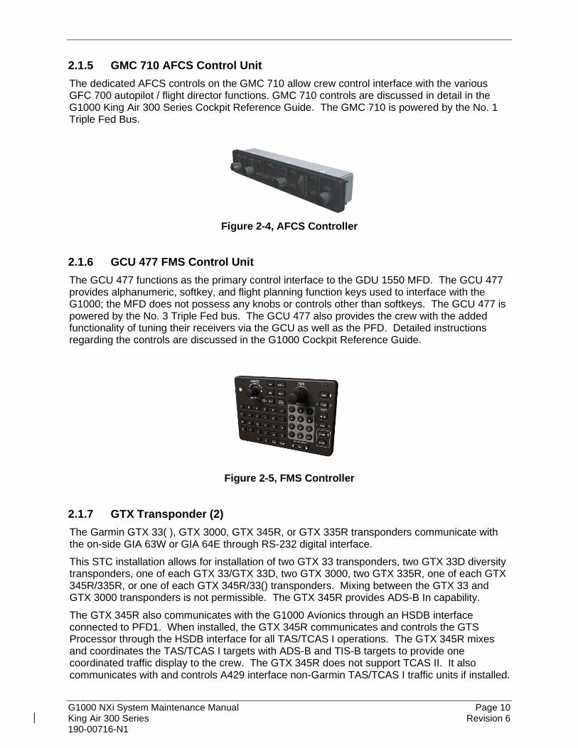
2.1.5 GMC 710 AFCS Control Unit The dedicated AFCS controls on the GMC 710 allow crew control interface with the various GFC 700 autopilot / flight director functions. GMC 710 controls are discussed in detail in the G1000 King Air 300 Series Cockpit Reference Guide. The GMC 710 is powered by the No. 1 Triple Fed Bus.
Figure 2-4, AFCS Controller
2.1.6 GCU 477 FMS Control Unit The GCU 477 functions as the primary control interface to the GDU 1550 MFD. The GCU 477 provides alphanumeric, softkey, and flight planning function keys used to interface with the G1000; the MFD does not possess any knobs or controls other than softkeys. The GCU 477 is powered by the No. 3 Triple Fed bus. The GCU 477 also provides the crew with the added functionality of tuning their receivers via the GCU as well as the PFD. Detailed instructions regarding the controls are discussed in the G1000 Cockpit Reference Guide.
Figure 2-5, FMS Controller
2.1.7 GTX Transponder (2) The Garmin GTX 33( ), GTX 3000, GTX 345R, or GTX 335R transponders communicate with the on-side GIA 63W or GIA 64E through RS-232 digital interface. This STC installation allows for installation of two GTX 33 transponders, two GTX 33D diversity transponders, one of each GTX 33/GTX 33D, two GTX 3000, two GTX 335R, one of each GTX 345R/335R, or one of each GTX 345R/33() transponders. Mixing between the GTX 33 and GTX 3000 transponders is not permissible. The GTX 345R provides ADS-B In capability. The GTX 345R also communicates with the G1000 Avionics through an HSDB interface connected to PFD1. When installed, the GTX 345R communicates and controls the GTS Processor through the HSDB interface for all TAS/TCAS I operations. The GTX 345R mixes and coordinates the TAS/TCAS I targets with ADS-B and TIS-B targets to provide one coordinated traffic display to the crew. The GTX 345R does not support TCAS II. It also communicates with and controls A429 interface non-Garmin TAS/TCAS I traffic units if installed.

G1000 NXi System Maintenance Manual Page 11 King Air 300 Series Revision 6 190-00716-N1
For TCAS II operations, the GTX 3000 transponder communicates with the GTS Processor or Collins TTR-920/4000 traffic units through ARINC 429 digital interfaces (transmit and receive). Only the GTX 3000 supports TCAS II operations with the GTS Processor. The GTX 3000 or Collins TDR-94 transponders support TCAS II operations with the Collins TTR-920/4000 traffic units. The transponder units are mounted on the upper avionics equipment shelf in the tail section of the airplane. Power is provided by the No. 1 GTX from Triple Fed Avionics Bus. The No. 2 GTX is powered from Left Gen Avionics Bus. All GTX transponders (non-diversity and diversity) interface with a transponder antenna mounted to the bottom of the fuselage. Each GTX diversity transponder (GTX33D and GTX 3000) interfaces to a transponder antenna mounted to the top of the fuselage.
GTX 33()
GTX 3000
GTX 345R/GTX 335R
Figure 2-6, Transponders

G1000 NXi System Maintenance Manual Page 12 King Air 300 Series Revision 6 190-00716-N1
2.1.8 GIA 63W or GIA 64E Integrated Avionics Unit (2) Two Garmin GIA 63W or GIA 64E Integrated Avionics Units (IAUs) contain the VHF COM/NAV receivers, WAAS GPS receiver, Flight Director, and system integration microprocessors. The GIAs also serve as a communication interface to all other G1000 LRUs in the system. Each GIA 63W or GIA 64E communicates directly with the on-side GDU 1050A display using a HSDB Ethernet connection. Both GIAs are located remotely in the nose equipment bay. Each GIA 63W or GIA 64E communicates directly with the on-side GDU 1050A display using a HSDB Ethernet connection. The GIA 63W (011-01105-01) unit is approved for use in the King Air 300 Series with the Garmin NXi system. Previously, only the GIA 63W (011-01105-20) was approved for use in the legacy G1000 system. The GIA 64E also provides the additional capability to interface to an existing Flight Data Recorder system via an ARINC 717 Interface. A separate approval is required by the installer for the installation of a Flight Data Recorder system. Both GIAs are located remotely in the nose equipment bay. GIA 1 receives primary electrical power from No. 1 Triple Fed Bus and a secondary electrical power supply from Center Bus. GIA 2 receives electrical power from No. 3 Triple Fed Bus. The GIA 1’s COM power supply (COM 1) is provided by No. 1 Triple Fed Bus. GIA 2’s COM power supply (COM 2) is provided by No. 3 Triple Fed Bus. Therefore, both GIAs power-up immediately with external or aircraft power or battery operation. Both GIA 63Ws or GIA 64Es interface to the following equipment:
• Existing VOR/LOC/Glideslope Antenna System • Existing VHF COM #1 & #2 Antennas • GA 36 and GA 37 GPS/WAAS Antennas • GMA 1347D or GMA 1360D, #1 & #2 • GEA 71 or GEA 71B, #1 & #2 • GSA 80 and GSA 9000 Servo Motors • GRS 77 or GRS 7800, #1 & #2
and a or GSU 75 #1 & #2 (ADAHRS) GDC 7400 #1 & # 2
• A429 Interface Traffic Systems (if installed) The GIA 63W or GIA 64E #1 interfaces to the following additional equipment:
• GTX 33( )#1, GTX 3000 #1, GTX 345R #1, or GTX 335R#1 • DME 42 (if installed) • GSR 56 (if installed per stand-alone configuration) • GDU 1050A #1
The GIA 63W or GIA 64E #2 interfaces to the following additional equipment:
• GTX 33( )#2, GTX 3000 #2, or GTX 335R#2 • ADF (if installed) • Stormscope (if installed) • Radar Altimeter (if installed) • GDU 1050A #2

G1000 NXi System Maintenance Manual Page 13 King Air 300 Series Revision 6 190-00716-N1
Figure 2-7, GIA unit
2.1.9 GEA 71/71B Engine/Airframe Unit (2) The Garmin GEA 71 (if GIA 63W units are installed) and GEA 71B (if GIA 64E units are installed) Engine/Airframe Units provide engine/airframe data to the G1000 system. Data received from transducers/sensors is processed and sent to GIA 63Ws or GIA 64Es (via RS-485 digital interface), and subsequently to the GDU 1550 MFD. Engine parameters are normally displayed on the MFD. In the event of MFD failure, the engine parameters can be displayed on PFD 1 and/or PFD 2 using display reversion. The GEAs are located behind the instrument panel and is mounted in a vertical orientation. Electrical power to GEA 1 is provided from No. 1 Triple Fed Bus and to GEA 2 from No. 2 Triple Fed Bus. Both GEA units will power-up immediately with external or aircraft power or battery operation. Each GEA interfaces to the following sensors for its onside engine:
• Oil Pressure Sensor • Oil Temperature Sensor • Fuel Flow Sensor (via onside Signal Conditioner) • Turbine Speed Sensor (via onside Signal Conditioner) • Propeller Speed Sensor (via onside Signal Conditioner) • Torque Sensor • Interstage Turbine Temperature (ITT) Sensor
Figure 2-8, GEA unit

G1000 NXi System Maintenance Manual Page 14 King Air 300 Series Revision 6 190-00716-N1
2.1.10 GSU 75B ADAHRS (2) The GSU 75 ADAHRS is a combined Air Data and AHRS system. The units are mounted in the nose equipment bay, contain advanced tilt sensors, accelerometers, rate sensors, static pressure sensors, and pitot pressure sensors. The GSU 75B(s) receive GPS data from onside and offside GIA 63W(s) or GIA 64E(s), and magnetic heading from the onside GMU 44 Magnetometer. The #2 GSU ADAHRS units can provide heading data to an approved third party TCAS II device through an ARINC 429 digital interface. GSU 1 receives primary electrical power from the No. 1 Triple Fed Bus and a secondary power supply from the Center Bus. GSU 2 receives electrical power from the No. 3 Triple Fed Bus. The GSU(s) provide electrical power to the onside GMU 44 Magnetometer and the onside GTP 59 OAT probe. GSU 1 and GSU 2 connect to existing pitot/static ports. Refer to Figure 2-28 for a schematic of the aircraft’s pitot/static system and its connections to the G1000 STC installed equipment. Each GSU 75B provides the following information via ARINC 429 busses to both the onside and offside GIA 63W(s) or GIA 64E(s) and PFD(s). GSU #1 also provides this information to the MFD.
• Aircraft altitude and airspeed
• Aircraft vertical speed, Mach and outside air temperature
• Aircraft heading, pitch and roll
• Aircraft yaw, pitch and roll rates
• Aircraft body-axis accelerations
• Rates of change of heading, pitch and roll
• Aircraft accelerations expressed in a local level frame of reference GSU 75B(s) are installed in lieu of separate ADC (GDC 7400) and AHRS (GRS 77 or GRS 7800). For this STC, mixed ADAHRS and ADC/AHRS configurations are not permitted.
IMPORTANT! Aircraft modified by this STC are eligible to be approved for RVSM operation. RVSM critical maintenance instructions contained in this document must be followed in order to guarantee performance within RVSM specifications.
Figure 2-9, GSU-75B ADAHRS with Connector and Mounting Tray

G1000 NXi System Maintenance Manual Page 15 King Air 300 Series Revision 6 190-00716-N1
2.1.11 Digital Air Data Computer (2) (optional) The optional Garmin GDC 7400 air data computers may be installed along with AHRS units in lieu of GSU 75B(s). The GDC(s) compile information from the pitot/static system and outside air temperature (OAT) sensors to provide digital air data computations to the G1000 system. The GDC communicates with the GIA 63W or GIA 64E, GDU 1050A, and GRS 77/7800 using ARINC 429 digital interface. The unit is mounted behind the instrument panel. GDC 1 also communicates using ARINC 429 with the GDU 1550 MFD. GDC 1 receives primary electrical power from the Essential Bus and a secondary power supply from Dual Fed Bus No. 1. GDC 2 receives power from Dual Fed Bus No. 2. GDC 1 and GDC 2 connect to existing pitot/static ports. Refer to Figure 2-27 for a schematic of the aircraft’s pitot/static system and its connections to the G1000 STC installed equipment.
IMPORTANT! Aircraft modified by this STC are eligible to be approved for RVSM operation. RVSM critical maintenance instructions contained in this document must be followed in order to guarantee performance within RVSM specifications.
Figure 2-10, GDC 7400 Air Data Computer
2.1.12 OAT Temperature Probe (2) The Garmin GTP 59 OAT Probes provide the GSU 75B or optional GDC 7400 with outside air temperature data. The OAT temperature probes are mounted to the bottom of the fuselage at F.S. 113.5.
Figure 2-11, OAT probe

G1000 NXi System Maintenance Manual Page 16 King Air 300 Series Revision 6 190-00716-N1
2.1.13 Attitude & Heading Reference System (2) (optional) The optional Garmin GRS 77 AHRS or GRS 7800 AHRS units may be installed along with ADC units in lieu of GSU 75B(s). They provide attitude and heading information to the G1000 system. The units, mounted in the nose equipment bay, contain advanced tilt sensors, accelerometers, and rate sensors. The unit interfaces with the Garmin Air Data Computers and GMU44 Magnetometer and utilizes GPS signals from the GIA 63Ws or GIA 64Es. Actual attitude and heading information is sent using ARINC 429 digital interface to both GDU 1050As and GIA 63Ws or GIA 64Es. The GRS interfaces with and provides power to the GMU 44 Magnetometer. The GRS supplies attitude and heading information directly to the PFDs, MFD, and GIAs. The #2 GRS AHRS units can provide heading data to an approved third party TCAS II device through an ARINC 429 digital interface. Additionally, the GRS 7800 AHRS provides heading with or without the aiding of the Garmin GMU 44 magnetometer. When operating without the aid of the magnetometer, the GRS 7800 is functionally similar to that of a Directional Gyro. GRS 1 receives primary electrical power from No. 1 Triple Fed Bus and a secondary power supply from the Center Bus. GRS 2 receives electrical power from No. 3 Triple Fed Bus.
GRS 77
GRS 7800
Figure 2-12, AHRS

G1000 NXi System Maintenance Manual Page 17 King Air 300 Series Revision 6 190-00716-N1
2.1.14 GMU 44 Magnetometer (2) The GMU 44 provides horizontal and vertical magnetic field information to the GSU or GRS. This allows heading to be calculated and provides assistance during ADAHRS/AHRS alignment. The GMU 44 units are mounted in the tailcone or in the horizontal stabilizer. The 011-00870-20 GMU 44 units may only be installed in the horizontal stabilizer. The GMU 44 units were modified to account for low clearance installations and have a 90-degree pig-tail harness versus the straight harness on the 011-08870-10 GMU 44 units. The units receive power directly from the GSU/GRS units and communicate with the GSU/GRS units via an RS-485 digital interface.
GMU 44 -00 & -10 Unit GMU 44 -20 Unit
Figure 2-13, Magnetometer
2.1.15 GDL 69A/69A SXM Datalink The GDL 69A/69A SXM provides the interface to the GWX 68, GWX 70, or GWX 75 weather radar and optional GDL59 Wi-Fi datalink by acting as a communications hub between the MFD and GWX and GDL 59 via HSDB. The GDL 69A/69A SXM also provides SiriusXM Radio weather and music entertainment through means of a dedicated satellite data link. The GDL 69A/69A SXM is mounted behind the instrument panel. Power to the GDL 69A/69SXM is received from Right Gen Avionics Bus. The GDL 69A/69A SXM sends weather data through the HSDB bus to the MFD, where the data link interface is controlled. Digital audio is sent directly to the GMA 1347D or GMA 1360D Audio Panel. Optional remote control (GRC 10) and remote control transceiver (GRT 10) may be interfaced with the GDL 69A/69A SXM. Installation of the GRC 10 and GRT 10 is in accordance with Garmin STC SA01487SE or other approved data. Refer to the approved Instructions for Continued Airworthiness information for these units. It is recommended that GRT 10 be powered from the Entertainment Bus.
Figure 2-14, GDL 69A/69A SXM Datalink
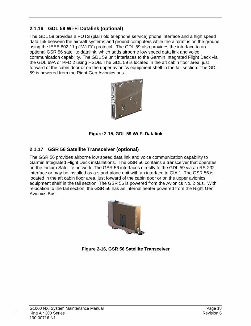
G1000 NXi System Maintenance Manual Page 18 King Air 300 Series Revision 6 190-00716-N1
2.1.16 GDL 59 Wi-Fi Datalink (optional) The GDL 59 provides a POTS (plain old telephone service) phone interface and a high speed data link between the aircraft systems and ground computers while the aircraft is on the ground using the IEEE 802.11g (“Wi-Fi”) protocol. The GDL 59 also provides the interface to an optional GSR 56 satellite datalink, which adds airborne low speed data link and voice communication capability. The GDL 59 unit interfaces to the Garmin Integrated Flight Deck via the GDL 69A or PFD 2 using HSDB. The GDL 59 is located in the aft cabin floor area, just forward of the cabin door or on the upper avionics equipment shelf in the tail section. The GDL 59 is powered from the Right Gen Avionics bus.
Figure 2-15, GDL 59 Wi-Fi Datalink
2.1.17 GSR 56 Satellite Transceiver (optional) The GSR 56 provides airborne low speed data link and voice communication capability to Garmin Integrated Flight Deck installations. The GSR 56 contains a transceiver that operates on the Iridium Satellite network. The GSR 56 interfaces directly to the GDL 59 via an RS-232 interface or may be installed as a stand-alone unit with an interface to GIA 1. The GSR 56 is located in the aft cabin floor area, just forward of the cabin door or on the upper avionics equipment shelf in the tail section. The GSR 56 is powered from the Avionics No. 2 bus. With relocation to the tail section, the GSR 56 has an internal heater powered from the Right Gen Avionics Bus.
Figure 2-16, GSR 56 Satellite Transceiver

G1000 NXi System Maintenance Manual Page 19 King Air 300 Series Revision 6 190-00716-N1
2.1.18 GSD 41 Data Concentrator (optional) The GSD 41 interfaces to various airframe discrete outputs to support third party systems such as Flight Data Recorders. The GSD 41 is located on the avionics shelf in the tail area. The GSD 41 is powered from No. 2 Triple Fed Bus.
Figure 2-17, GSD 41 Data Concentrator
2.1.19 GTS 820 (TAS)/GTS 850 (TCAS-I) Traffic System (optional) The GTS 820/850 is a traffic surveillance system that uses active interrogation of Mode S and Mode C transponders to provide traffic advisories to the pilot. The GTS 820 is a TAS unit; the GTS 850 is a TCAS I unit. The installation includes a top directional antenna (GA 58) paired with a GPA 65 power amplifier / low noise amplifier (PA/LNA) unit and a bottom, unamplified GA 58 antenna. The GTS 820/850 is located in the nose avionics bay on the top, left shelf. The GPA 65 is located in the left sidewall area, just in front of the most forward cabin window. The GTS 820/850 traffic system is powered from the Right Gen Avionics bus.
Figure 2-18, GTS 820/850 Traffic System
2.1.20 GTS Traffic Processor (optional) The GTS Traffic Processor is a microprocessor-based Line Replaceable Unit that uses active interrogations of Mode S and Mode A/C transponders to provide Traffic Advisories and Resolution Advisories (GTS 8000 only) to the pilot. The GTS Processor can be configured as TAS (GTS 825), TCAS I (GTS 855), or TCAS II (GTS 8000). The GTS traffic processor is installed in the nose avionics bay. The GTS interfaces to the GA 58 traffic antennas which are mounted on the upper and lower fuselage. The GTS traffic processor also interfaces with the GTX 3000 (when installed) through ARINC 429 digital data lines. When a GTX 345R is installed, The GTX communicates with the GTS processor via the G1000 HSBD bus. The GTS traffic processor is powered from the Right Gen Avionics Bus.

G1000 NXi System Maintenance Manual Page 20 King Air 300 Series Revision 6 190-00716-N1
Figure 2-19, GTS Traffic Processor
2.1.21 Weather Radar The GWX 68, GWX 70, or GWX 75 Airborne Weather Radar provides weather radar data output to the GDU 1550 MFD and to the GDU 1050A PFD(s). The GWX is mounted forward of the forward bulkhead at F.S. 30. Power to the GWX is received from the Left Gen Avionics bus. In most installations, data received from the GWX is routed by HSDB through the GDL 69A data link unit to the MFD (if a GDL 69 unit is installed) or otherwise wired direct to the MFD via high-speed data bus (Ethernet).
Figure 2-20, Weather Radar
2.1.22 GSA 80 Servos and GSM 86 Servo Gearboxes (3) The Garmin GFC 700 AFCS uses GSA 80 high torque servos to automatically control aircraft pitch, pitch trim, and roll. The pitch trim variant of the GSA 80 is a high speed servo actuator. The GSA 80 contains a motor-control and monitor circuit board, as well as a solenoid and a brushless DC motor. The GSA 80 servo receives serial RS-485 data packets from the GIA 63Ws or GIA 64Es. The roll servo is located in the forward cabin lower fuselage at F.S. 185. The pitch, yaw, and pitch trim servos are located in the tail. The roll servo is located in the forward cabin lower fuselage near the wing front spar. The pitch and pitch trim servos are located in the tail. Power to the servos is received from No. 2 Triple Fed Bus. All servos mount to Garmin GSM 86 Servo Gearboxes. The GSM 86 is responsible for transferring the output torque of the GSA 80 servo actuators to the mechanical flight control surface linkage. The GSM 86 has a clutch cartridge that cannot be adjusted to a different torque value.

G1000 NXi System Maintenance Manual Page 21 King Air 300 Series Revision 6 190-00716-N1
Figure 2-21, Servo
2.1.23 GSA 9000 Servo and GSM 9100 Servo Gearbox The Garmin GFC 700 AFCS uses a GSA 9000 servo to control aircraft yaw damper/turn coordination and rudder boost. The GSA 9000 contains a motor-control and monitor circuit board, as well as a solenoid and a brushless DC motor. The GSA 9000 servo receives serial RS-485 data packets from the GIA 63Ws or GIA 64Es. The GSA 9000 yaw servo is located in the tail. Power to the servo is received from No. 2 Triple Fed Bus. The servo mounts to a Garmin GSM 9100 Servo Gearbox. The GSM 9100 is responsible for transferring the output torque of the GSA 9000 servo actuator to the mechanical flight control surface linkage.
Figure 2-22, GSA 9000 / GSM 9100 2.1.24 GRA 5500 Radar Altimeter The GRA 5500 Garmin Radar Altimeter is designed to calculate the height Above Ground Level (AGL) of the aircraft which is displayed on the PFDs. For King Air installations, the GRA 5500 is configured to output the value height Above Ground Level to the pilot through the GDU. The GRA interfaces to the existing radar altimeter antennas and GIA #2 via the ARINC 429 or RS-422 digital bus. The GRA 5500 is located below the lower avionics equipment shelf in the tail section. The GRA 5500 is powered from the Right Gen Avionics Bus.
Figure 2-23, GRA 5500 Radar Altimeter

G1000 NXi System Maintenance Manual Page 22 King Air 300 Series Revision 6 190-00716-N1
2.1.25 Garmin G36 and 37 GPS/WAAS Antennas This installation uses one G36 GPS/WAAS antenna and a G37 GPS/WAAS/XM antenna. The antennas are located in the upper, forward cabin.
2.1.26 Signal Conditioner (2) Each GEA 71/71B receives signals from its on-side engine turbine speed sensor, propeller speed sensor and fuel flow sensors via a Meggitt Signal Conditioner, p/n 85-292-4. This unit converts the signals from the engine sensors to a signal usable by the GEA 71/71B. These units are installed behind the instrument panel. Electrical power to the No. 1 Engine Signal Conditioner is provided from No. 1 Triple Fed Bus and to the No. 2 Engine Signal Conditioner from No. 2 Triple Fed Bus. Both signal conditioners will power-up immediately with external or aircraft power or battery operation.
2.1.27 Standby Indicators This STC has two options for standby primary flight indications. The first option is a Mid-Continent Instruments MD 302 Standby Attitude Module that provides attitude, airspeed, and altitude indications in one electronic assembly. The second option consists of three separate mechanical indicators, one each for airspeed, altitude, and attitude.
2.1.27.1 Mid-Continent Instruments MD 302 Standby Attitude Module (SAM) Mid-Continent Instruments, part number 6420302-2, is an electronic 3-in-1 standby indicator assembly instrument with two 2.4” diagonal LCD displays provides standby altitude, airspeed, and attitude information to the cockpit. It is powered from Standby Instrument Bus and the emergency standby battery. Lighting Control is connected to the No.1 Dual Fed Bus. It receives static and pitot pressures from the right-hand pitot/static system. The MD 302 is a standalone unit and does not interface to any G1000 avionics. The MD302 is installed on the main instrument panel, between the pilot’s PFD and the MFD.
Figure 2-24, MD 302 Standby Attitude Module

G1000 NXi System Maintenance Manual Page 23 King Air 300 Series Revision 6 190-00716-N1
2.1.27.2 Mechanical (Analog) Standby Indicators
2.1.27.2.1 Standby Airspeed Indicator An optional Standby Airspeed indicator (part numbers listed on General Arrangement drawing) is installed between PFD 1 and the MFD. The standby airspeed indicator does not require electrical power for normal operation except for internal instrument lighting, which is powered from No. 3 Triple Fed Bus and the emergency standby battery. This unit is connected to the right-side pitot/static system.
2.1.27.2.2 Standby Altimeter An optional standby altimeter (part numbers listed on General Arrangement drawing) is installed between PFD 1 and the MFD. This unit incorporates a vibrator to ensure accurate display altitude information. The vibrator is powered by No. 3 Triple Fed Bus and the emergency standby battery. Internal lighting of this unit is powered from Left Gen Bus and the emergency standby battery. This unit is connected to the right-side static system.
2.1.27.2.3 Standby Attitude Indicator The optional Mid-Continent Electric Attitude Indicator (part number listed on General Arrangement drawing) is used as the standby attitude indicator. It is powered by No. 3 Triple Fed Bus and the emergency standby battery. Gyro power and internal lighting of this unit is powered from Left Gen Bus and the emergency standby battery.
2.1.28 L-3 PS-835 (C or D Model) Emergency Standby Battery In the event of loss of all normal electrical power, the battery is designed to provide 24 Vdc (nominal) emergency power source for the following items:
• standby attitude indicator (operation and internal lighting)
• standby altimeter (vibrator and internal lighting)
• standby airspeed indicator (lighting only)
• pilot side glareshield lighting
• magnetic compass The aircraft power buss provides a trickle charge to the PS-835 under normal conditions. This battery is installed in the nose avionics bay. It is controlled using the standby battery switch indicator on the instrument panel.
2.2 G1000 Optional Interfaces Optional equipment interfaces include lightning detection, traffic systems, radar altimeter, ADF systems and DME systems. The G1000 also provides a general purpose ARINC bus for use with third party entertainment and cabin equipment. Refer to wiring diagram listed in Table 1-1, for specific interface information.

G1000 NXi System Maintenance Manual Page 24 King Air 300 Series Revision 6 190-00716-N1
2.3 Electrical Power Distribution This airplane uses a multi-bus system, as detailed below and in Figure 2-25. This Figure shows the system post installation of this STC. Although this STC made several bussing changes to the distribution system, the core electrical generation and distribution system remains unchanged from the basic airplane design. Figure 2-26 shows the power sources for all equipment used by this STC. Each bus used or modified by this installation is described below. Left and Right Generator Buses: The left and right generator buses receive power from their respective left and right generators. The left and right generator buses also support Center Buses and Left Gen and Right Gen Avionics Buses, respectively. Triple Fed Bus: The Triple Fed bus is powered by left and right generator buses and the battery bus. Avionics Buses: The Left Gen Avionics bus is powered from the Left Generator Bus via the Avionics No. 1 relay. The Right Gen Avionics Bus is powered from the Right Generator Bus via the Avionics No. 2 relay. The Triple Fed Avionics Bus is powered from the Triple Fed bus via the Avionics No. 3 relay. All avionics relays are controlled using the Avionics Master Switch. Left and Right Engine Instrument Buses: On serial numbers FL-120, FL-122 through FL-380, FL-382, FM-009 through FM-11, the electrical system includes the L ENG INSTR and R ENG INSTR buses. On all other serial numbers, these two buses are not installed and engine instruments are powered directly from the Triple Fed Buses. Emergency Standby Battery: The Standby Emergency Battery (STBY BATT) system in the King Air 300/B300 is designed to provide uninterrupted DC power to the Standby Attitude indicator (including gyro motor and internal instrument lighting), the Standby Altimeter (including vibrator and internal instrument lighting), standby airspeed indicator internal instrument lighting and internal instrument lighting for the magnetic compass from the L-3 PS-835(C or D Model) Emergency Standby Battery. This standby battery power is independent from the normal electrical system and provides redundant power for the standby instruments in the event that all other electrical power is lost.

G1000 NXi System Maintenance Manual Page 25 King Air 300 Series Revision 6 190-00716-N1

G1000 NXi System Maintenance Manual Page 26 King Air 300 Series Revision 6 190-00716-N1
Figure 2-25, 300 Series Electrical Distribution (Post G1000 STC)
Figure 2-26, G1000 Component Power Sources

G1000 NXi System Maintenance Manual Page 27 King Air 300 Series Revision 6 190-00716-N1
2.4 Electrical Load Utilization The following chart lists the electrical equipment and their associated loads for each of the standard and optional items installed on the King Air 300 series airplanes with the installation of G1000. The loads specified are used to verify the electrical buses, generating system and batteries are operated within their limits and capacity. For electrical load test procedure and electrical load test report, refer to Garmin documents 190-00716-N0 (Post Installation Checkout Procedure King Air 300 Series) and 005-00629-22 (Electrical Load Test Report G1000 integrated Avionics System Hawker/Beechcraft Model 300/B300 King Air) respectively.
Table 2-1, Electrical Loads
Equipment Units Used
Each Unit (Amps
DC) Part Number Notes
Battery Bus
Left Generator Bus
Avionics Left Generator Bus
GIA 63W – COM #2 or GIA 64E – COM #2
1
4.3 A Max See Note
011-01105-20 4.3 A – Transmitting 0.3 A – Not Transmitting
4.3 A Max See Note
011-03711-40 4.3 A – Transmitting 0.3 A – Not Transmitting
GTX 33 Transponder #2 or GTX 33D Transponder #2 or GTX 3000 Transponder #2 or GTX 335R #2
1
1.6 A 011-00779-30
1.6 A 011-00779-21
1.6 A 011-01997-00
0.29 A 011-03301-00
GWX 68 Weather Radar or GWX 70 Weather Radar or GWX 75 Weather Radar
1
2.0 A 011-00883-20
2.5 A 011-01768-00
2.5 A 010-01590-00

G1000 NXi System Maintenance Manual Page 28 King Air 300 Series Revision 6 190-00716-N1
Equipment Units Used
Each Unit (Amps
DC) Part Number Notes
Right Generator Bus
Avionics Right Generator Fed Avionics Bus
GDL 69A XM Data Link or GDL 69A SXM Data Link
1 0.35 A 011-00987-00
011-03177-10
GDL 59 Wi-Fi 1 0.572 A 011-01746-00
GTS Processor or GTS 820 Traffic Unit or GTS 850 Traffic Unit
1
2.5 A 011-02571-00
1.6 A 011-01446-00
1.6 A 011-01553-00
GRA 5500 Radio Altimeter 1 0.5A 011-02537-00
GSR 56 Iridium/Iridium Heater 1 1.86A
011-02268-00 or 011-02268-01
Center Bus
GDU 1050A PFD #1 1
0.9 A Max See Notes 011-03470-10
Secondary power input 0.7 A above -15°C 0.9 A below -15°C

G1000 NXi System Maintenance Manual Page 29 King Air 300 Series Revision 6 190-00716-N1
Equipment Units Used
Each Unit (Amps
DC) Part Number Notes
GRS 77/GMU 44 – AHRS #1 or GRS 7800/GMU 44 – AHRS #1 or GSU 75B/GMU 44 ADAHRS #1
1
0.3 A See Note
GRS 77: 011-00868-10 GMU 44: 011-00870-10 011-00870-20
Secondary power input Secondary power input Secondary power input
0.45 A See Note
GRS 7800: 011-02278-00 GMU 44: 011-00870-10 011-00870-20
0.38 A See Note
GSU 75B: 011-03094-40 GMU 44: 011-00870-10 011-00870-20
GDC 7400 - ADC #1 1 0.230 A See Note
011-02337-00 011-02337-01
Secondary power input
GIA 63W – NAV #1 or GIA 64E - NAV #1
1
1.0 A See Note
011-01105-20
Secondary power input 1.0 A
See Note 011-03711-40
No. 1 Triple-Fed Bus
PFD #1 - Cooling Fan 1 0.1 A
305468-00 (Sandia P/N) or 013- 00102-00 (Garmin P/N)
GIA 63W #1 - Cooling Fan or GIA 64E #1 - Cooling Fan
1 0.4 A 305467-00 (Sandia P/N) or

G1000 NXi System Maintenance Manual Page 30 King Air 300 Series Revision 6 190-00716-N1
Equipment Units Used
Each Unit (Amps
DC) Part Number Notes
013-00103-00 Garmin P/N)
GIA 63W – NAV #1 or GIA 64E - NAV #1
1 1.0 A 011-01105-20 Primary power input
1.0 A 011-03711-40
GIA 63W – COM #1 or GIA 64E - COM #1
1
4.3 A Max See Notes
011-01105-20 Primary power input 0.3 A – Not Transmitting 4.3 A – Transmitting 4.3 A Max
See Notes 011-03711-40
GMC 710 – AFCS Controller 1 0.16 A 011-01020-10
GRS 77/GMU44 –AHRS #1 or GRS7800/GMU44 – AHRS #1 or GSU 75B/GMU44 ADAHRS #1
11
0.3 A See Note
GRS 77: 011-00868-10 GMU 44: 011-00870-10 011-00870-20
Primary power input 0.45 A See Note
GRS 7800: 011-02278-00 GMU 44: 011-00870-10 011-00870-20
0.38 A See Note
GSU 75B: 011-03094-40 GMU 44: 011-00870-10 011-00870-20
GDC 7400 #1 1 0.230 A 011-02337-00 011-02337-01
Primary power input
GDU 1050A – PFD #1 1 0.9 A Max See Notes
011-03470-10 Primary power input 0.7 A above -15°C 0.9 A below -15°C

G1000 NXi System Maintenance Manual Page 31 King Air 300 Series Revision 6 190-00716-N1
Equipment Units Used
Each Unit (Amps
DC) Part Number Notes
GMA 1347D #1 – Audio Panel or GMA 1360D #1 – Audio Panel
1
1.75 A 011-01257-20
Primary power input 1.0 A 011-03568-20
Meggitt Sig Cond #1 1 0.032 A 85-292-4
GEA 71 #1 or GEA 71B #1
1 0.5A 011-00831-00
0.52A 011-03711-40
No. 2 Triple-Fed Bus
GSA 80 – Roll Servo 1 1.61 A 011-00877-20
GSA 80 – Pitch Servo 1 1.61 A 011-00877-20
GSA 9000 – Yaw Servo 1 1.80 A 011-02213-00 011-02213-10
GSA 80 – Pitch Trim Servo 1 1.61 A 011-00877-21
MFD Cooling Fan 1 0.1 A
305468-00 (Sandia P/N) or 013-00102-00 (Garmin P/N)
GDU 1550 – MFD 1 1.2 A Max See Note
011-03472-00
0.9 A – Temp above -15°C 1.2 A – Temp below -15°C
GSD 41 1 0.5 A 011-01457-00
GEA 71 #2 or GEA 71B #2
1 0.5 A 011-00831-00
0.52 A 011-03682-02
No.3 Triple Fed Bus
GDU 1050A – PFD #2 1 0.9 A Max See Notes
011-03470-10 0.7 A above -15°C 0.9 A below -15°C

G1000 NXi System Maintenance Manual Page 32 King Air 300 Series Revision 6 190-00716-N1
Equipment Units Used
Each Unit (Amps
DC) Part Number Notes
GRS 77/GMU 44 – AHRS #2 or GRS 7800/GMU 44 – AHRS #2 or GSU 75B/GMU 44 ADAHRS #2
1
0.3 A Total
GRS 77: 011-00868-10 GMU 44: 011-00870-10 011-00870-20
0.45 A Total
GRS 7800: 011-02278-00 GMU 44: 011-00870-10 011-00870-20
0.38 A
GSU 75B: 011-03094-40 GMU 44: 011-00870-10 011-00870-20
GDC 7400 – ADC #2 1 0.230 A 011-02337-00 011-02337-01
GIA 63W – NAV #2 or GIA 64E - NAV #2
1 1.0 A 011-01105-20
1.0 A 011-03711-40
GMA 1347D #2 – Audio Panel or GMA 1360D #2 – Audio Panel
1
1.75 A 011-01257-20
1.0 A 011-03568-20
GCU 477 – FMS CTL 1 0.085 A 011-01428-00

G1000 NXi System Maintenance Manual Page 33 King Air 300 Series Revision 6 190-00716-N1
Equipment Units Used
Each Unit (Amps
DC) Part Number Notes
Standby Battery 1 See Note 501-1228-03 or 501-1228-04
2.5 A for model PS-835C 5 A for model PS-835D
PFD #2 – Cooling Fan 1 0.1 A
305468-00 (Sandia P/N) or 013-00102-00 (Garmin P/N)
GIA #2 – Cooling Fan 1 0.4 A
305467-00 (Sandia P/N) or 013-00103-00 (Garmin P/N)
Meggitt Sig Cond #2 1 0.032 A 85-292-4
Avionics Bus Triple-Fed
GTX 33 Transponder #1 or GTX 33D Transponder #1 or GTX 3000 Transponder #1 or GTX 335R #1 or GTX 345R #1
1
1.6 A 011-00779-30
1.6 A 011-00779-21
1.6 A 011-01997-00
0.29 A 011-03301-00
0.36 A 011-03303-00
Standby Battery Bus
MD 302 Standby Indicator 1 0.22 A 6420302-2 0.9 A max when charging and heating battery.
Standby Attitude Indicator 1 0.25 A 4200-11 (MOD 2)

G1000 NXi System Maintenance Manual Page 34 King Air 300 Series Revision 6 190-00716-N1
Equipment Units Used
Each Unit (Amps
DC) Part Number Notes
Standby Altimeter 1
See Note
3A43.22.35F.28.1.FU (Thommen P/N), or
Vibrator 0.030 A Lighting 0.096 A
0.157 A total
16650-1172 Aerosonic P/N)
Standby Airspeed Indicator 1
0.050 A
MD25-300 (Mid-Continent Inst P/N), or
0.050 A 25030-0184 (Aerosonic Corp P/N)

G1000 NXi System Maintenance Manual Page 35 King Air 300 Series Revision 6 190-00716-N1
2.5 Pitot/Static System The following schematics shows the pitot-static system as modified by this installation:
DR
AIN
FOR
WAR
D P
RES
SUR
EBU
LKH
EAD
R/H
PIT
OT
MAS
T
L/H
PIT
OT
MAS
T
#1 A
IR D
ATA
CO
MPU
TER
#2 A
IR D
ATA
CO
MPU
TER
AFT
PRES
SUR
EBU
LKH
EAD
TOP
BOTT
OM
R/H
STA
TIC
POR
TS
L/H
STA
TIC
POR
TS
ALTE
RN
ATE
STAT
ICSE
LEC
TOR
VAL
VE
ALTE
RN
ATE
STAT
ICPO
RT
CO
PILO
T PF
D
MFD
PILO
T PF
DBO
TTO
M
TOP
DR
AIN
DR
AIN
OAT
PRO
BE
OAT
PRO
BE
DAT
A BU
S
Stan
dby
Airs
peed
Stan
dby
Altim
eter
Elec
troni
c St
andb
yIn
dica
tor
With
MD
302
Inst
alle
d
Figure 2-27, Pitot/Static System with ADC(s) and AHRS(s) Installed
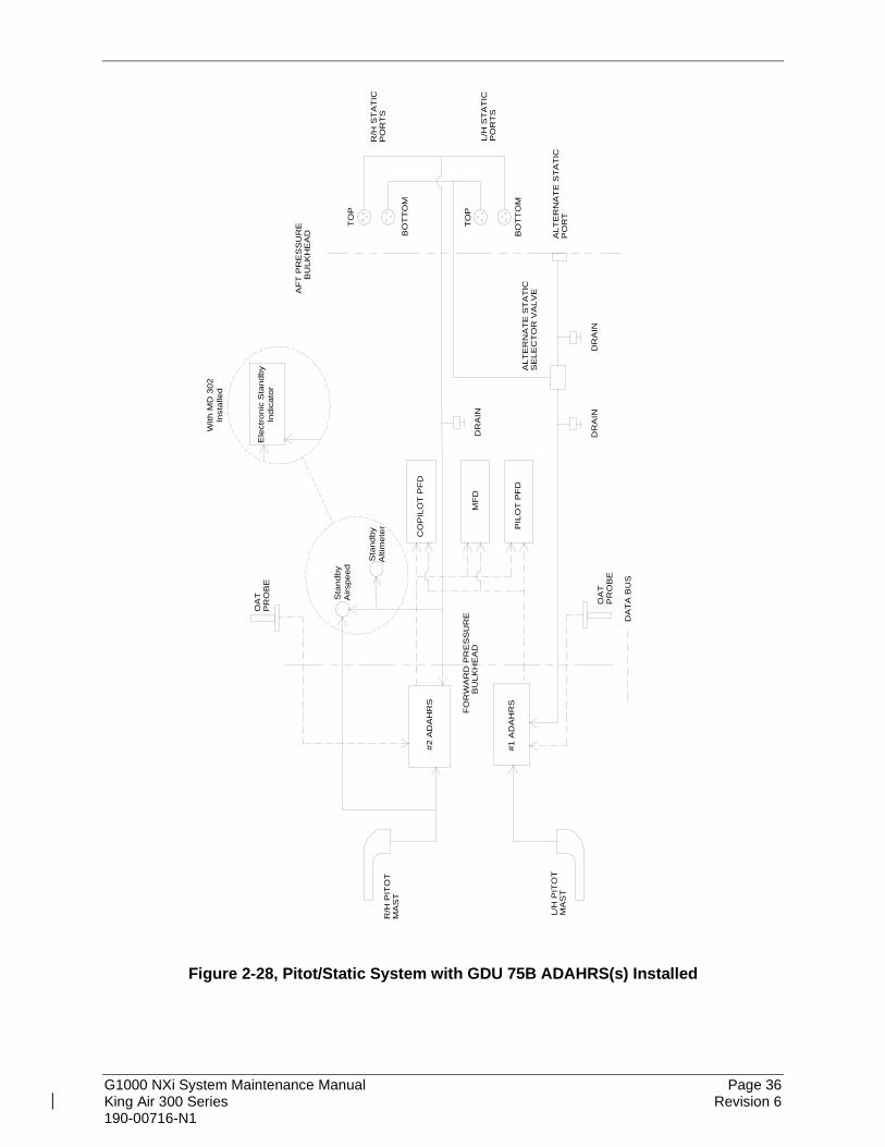
G1000 NXi System Maintenance Manual Page 36 King Air 300 Series Revision 6 190-00716-N1
DR
AIN
FO
RW
AR
D P
RE
SS
UR
EB
ULK
HE
AD
R/H
PIT
OT
MA
ST
L/H
PIT
OT
MA
ST
AF
T P
RE
SS
UR
EB
ULK
HE
AD
TO
P
BO
TT
OM
R/H
ST
AT
ICP
OR
TS
L/H
ST
AT
ICP
OR
TS
ALT
ER
NA
TE
ST
AT
ICS
ELE
CT
OR
VA
LVE
ALT
ER
NA
TE
ST
AT
ICP
OR
T
CO
PIL
OT
PF
D
MF
D
PIL
OT
PF
DB
OT
TO
M
TO
P
DR
AIN
DR
AIN
OA
TP
RO
BE
OA
TP
RO
BE
DA
TA
BU
S
Sta
ndby
Airs
peed
Sta
ndby
Alti
met
er
Ele
ctro
nic
Sta
ndby
Indi
cato
r
With
MD
302
Inst
alle
d
#1 A
DA
HR
S
#2 A
DA
HR
S
Figure 2-28, Pitot/Static System with GDU 75B ADAHRS(s) Installed

G1000 NXi System Maintenance Manual Page 37 King Air 300 Series Revision 6 190-00716-N1
2.6 Shield Block Grounds The connectors on Garmin G1000 LRUs utilize the Shield Block grounding system to provide necessary ground reference to wire shielding and/or transducers. The shield block termination method allows multiple grounds to be terminated directly to a block mounted to the connector backshell assembly. Shielding and grounding requirements for all other LRUs and connectors are shown in the respective install drawings.
2.7 G1000NXi /GFC700 Block Diagrams
GDU 1550 (MFD)
No. 1 GIA 64ESystem Integration
ProcessorsI/O Processors
VHF COMVHF NAV/LOC
GPSGlideslope
SBASVNAV
ESP/USP
AFCS Mode Logic No. 1 Flight Director
Servo Communication
No. 1 GEA 71BEngine / Airframe
Unit
GSA 80Roll Servo
GSA 80Pitch Trim Servo
GSA 80Pitch Servo
No. 1 GTX 3000/335R/345RMode S Transponder
No. 2 GMA1360D
GDL 69A Data Link(SXM Satellite WX & Radio)
No.1 GTP 59 OAT Probe
GMC 710 (AFCS Controller)
No. 1 GMU 44Magnetometer
GSA 9000Yaw Servo
DME
WX-500
No. 2 GIA 64ESystem Integration
ProcessorsI/O Processors
VHF COMVHF NAV/LOC
GPSGlideslope
SBASVNAV
ESP/USP
AFCS Mode Logic No. 2 Flight Director
Servo Communication
No. 2 GEA 71BEngine / Airframe
Unit
No. 2 GSU 75B ADAHRS
Attitude, Rate of Turn, Slip/Skid, Airspeed,
Altitude, Vertical Speed, OAT
No. 1 GSU 75B ADAHRS
Attitude, Rate of Turn, Slip/Skid, Airspeed,
Altitude, Vertical Speed, OAT
No. 2 GMU 44Magnetometer
No. 2 GTX 3000/335R
Mode S Transponder
No. 2 GTP59 OAT Probe
GDU 1050A (PFD2)No. 1 GMA1360D
GWX 75WX Radar
GDU 1050A (PFD1)
ADFADF
RAD ALT
GCU 477 FMS Controller
GDL 59Wi-Fi Data Link
GTS Processor Traffic
GSR 56Satellite Receiver
Figure 2-29, G1000NXi/GFC 700 Block Diagram with GSU 75B ADAHRS

G1000 NXi System Maintenance Manual Page 38 King Air 300 Series Revision 6 190-00716-N1
ADFADF
RAD ALT
GCU 477 FMS Controller
GDL 59Wi-Fi Data Link
GTS Processor Traffic
GSR 56Satellite Receiver
No. 2 GEA 71BEngine / Airframe
Unit
GDU 1050A (PFD1)
GDU 1550 (MFD)
No. 1 GIA 64ESystem Integration
ProcessorsI/O Processors
VHF COMVHF NAV/LOC
GPSGlideslope
SBASVNAV
ESP/USP
AFCS Mode Logic No. 1 Flight Director
Servo Communication
No. 1 GDC 7400Air Data Computer Airspeed, Altitude,
Vertical Speed, OAT
No. 1 GEA 71BEngine / Airframe
Unit
GSA 80Roll Servo
GSA 80Pitch Trim Servo
GSA 80Pitch Servo
No. 1 GTX 3000
Mode S Transponder
No. 2 GMA1360D
No.1 GTP 59 OAT Probe
GMC 710 (AFCS Controller)
No. 1 GMU 44Magnetometer
GSA 9000Yaw Servo
DME
WX-500
No. 2 GIA 64ESystem Integration
ProcessorsI/O Processors
VHF COMVHF NAV/LOC
GPSGlideslope
SBASVNAV
ESP/USP
AFCS Mode Logic No. 2 Flight Director
Servo Communication
No. 2 GDC 7400Air Data Computer Airspeed, Altitude,
Vertical Speed, OAT
No. 2 GRS 7800 AHRSAttitude
Rate of TurnSlip/Skid
No. 1 GRS 7800 AHRSAttitude
Rate of TurnSlip/Skid
No. 2 GMU 44Magnetometer
No. 2 GTX /3000
Mode S Transponder
No. 2 GTP59 OAT Probe
GDU 1050A (PFD2)No. 1 GMA1360D
GWX 75WX Radar
GDL 69A Data Link(SXM Satellite WX & Radio)
Figure 2-30, G1000NXi/GFC 700 Block Diagram with Separate ADC and AHRS

G1000 NXi System Maintenance Manual Page 39 King Air 300 Series Revision 6 190-00716-N1
2.8 GDU 1050A and GDU 1550 Displays Figure 2-31 and Figure 2-32 provide identification of the GDU 1050A PFD and GDU 1550 MFD controls.
Figure 2-31, GDU 1050A Control Interface
Figure 2-32, GDU 1550 Control Interface

G1000 NXi System Maintenance Manual Page 40 King Air 300 Series Revision 6 190-00716-N1
2.9 Softkeys Some pages have commands or selections that are activated by the GDU 1050A and GDU 1550 softkeys. If a softkey is associated with a command, that command will be displayed directly above the key. A grayed-out softkey shows a command that is unavailable. A softkey that is highlighted (green bar) shows the current active selection.
Figure 2-33, G1000 Softkeys
2.10 FMS Knob The FMS knob is the primary control for the G1000 system. To cycle through different configuration screens:
To change page groups: Rotate the large FMS knob. To change pages in a group: Rotate the small FMS knob.
To activate the cursor for a page, press the small FMS knob directly in, as one would push a regular button. To cycle the cursor through different data fields, rotate the large FMS knob. To change the contents of a highlighted data field, rotate the small FMS knob. This action either brings up an options menu for the particular field, or in some cases allows the operator to enter data for the field. To confirm a selection, press the ENT key. To cancel a selection, press the small FMS knob in again, deactivating the cursor. The CLR key may also be used to cancel a selection or deactivate the cursor.

G1000 NXi System Maintenance Manual Page 41 King Air 300 Series Revision 6 190-00716-N1
2.11 GCU 477 - MFD Controller The MFD controls are located on the GCU 477 as shown in the following figure:
Range / pan knob
Flight planning keys
FMS Ctrl knob
Alpha entrykeys
NumericEntry keys
Comm / Nav / Tranponder
keys
Figure 2-34, MFD Controls (GCU 477 shown)
2.12 GMC 710 - AFCS Controls The dedicated AFCS controls located on the GMC 710 are discussed in detail in the G1000 Cockpit Reference Guide. The following figure is provided for reference:
Figure 2-35, AFCS Controls (GMC 710 shown)

G1000 NXi System Maintenance Manual Page 42 King Air 300 Series Revision 6 190-00716-N1
2.13 GMA Audio Panels 2.13.1 GMA 1347D Audio Panel The following Figure shows the audio panel controls.
Transceiver Audio
Telephone
Speaker
Marker Beacon SignalSensitivity
Transceiver Audio
Passenger Address
Music
Marker Beacon Mute
Transmitters
Digital Recording Playback
Cabin Intercom
Master VOL (Large Knob)
Reversionary Mode
Aircraft NavigationRadio Audio
Manual Squelch
Intercom System (ICS)
ICS VOL SQ (Small Knob)
Figure 2-36, GMA 1347D Controls

G1000 NXi System Maintenance Manual Page 43 King Air 300 Series Revision 6 190-00716-N1
2.13.2 GMA 1360D Audio Panel The following Figure shows the audio panel controls.
Figure 2-37, GMA 1360D Controls

G1000 NXi System Maintenance Manual Page 44 King Air 300 Series Revision 6 190-00716-N1
2.14 G1000 Normal Mode To start the G1000 system in Normal Mode:
1. With a ground power unit connected to the external power receptacle, turn ON the BAT (battery) and EXT PWR switches. The following G1000 equipment is powered on:
• PFD displays & MFD display
• GSU 75 ADAHRS or GRS 77/GRS 7800 AHRS Units
• GDC 7400 Air Data Computers (if installed)
• GIA #1 and GIA #2 (COM listed separately)
• GEA 71 or GEA 71B Engine/Airframe Units
• GCU 477 FMS Control Unit
• GMC 710 Autopilot Control Unit
• GMA 1347D or GMA 1360D Digital Audio Panel Units
• GSA Servos
• GSD 41 Data Concentrator (Optional) 2. Turn ON the AVIONICS MASTER switch. The following G1000 equipment is powered
on:
• GTX Mode S Transponders
• GDL 69A Datalink Unit
• GWX 68, GWX 70, or GWX 75 Weather Radar Unit
• GTS 820/850 or GTS Processor Traffic System
• GDL 59 / GSR 56 Wi-Fi/Satellite (Optional)
• GRA 5500 Radar Altimeter (Optional) The G1000 system is now powered in the normal mode. In the normal operating mode, data fields that are invalid have large red X’s through them. A valid field does not display a red X. Allow the displays to initialize for approximately one minute for the red X’s to be removed. The GDC 7400 air data computers may require a longer initialization period than other G1000 units. This longer initialization period may cause the airspeed, altitude, vertical speed, and OAT fields to be invalid during PFD power-up which is normal until the GDC 7400 units are initialized.
The PFDs and MFD will function as specified in the G1000 Cockpit Reference Guide when the system has been correctly installed and configured.

G1000 NXi System Maintenance Manual Page 45 King Air 300 Series Revision 6 190-00716-N1
Figure 2-38, Normal Mode
2.15 Reversionary Mode Reversionary mode allows for display of information related to safe flight in the event of a display communication or hardware failure. The pilot’s PFD automatically goes into reversionary mode when communication to the MFD is lost. Manual reversionary mode allows the operator to force the pilot or copilot’s PFD into reversionary mode by pressing the large red button labeled ‘DISPLAY BACKUP’ on the respective GMA 1347D or GMA 1360D audio panel.
NOTE When the ‘DISPLAY BACKUP’ button is pushed to exit reversionary mode, there is a 5-second delay until the display returns to normal mode. If the ‘DISPLAY BACKUP’ button is pushed again during this 5-second delay, the display will reset the five second delay timer.
Figure 2-39, Automatic Reversion with MFD failure
Figure 2-40, Manual Reversion with pilot PFD failure

G1000 NXi System Maintenance Manual Page 46 King Air 300 Series Revision 6 190-00716-N1
3. SOFTWARE AND CONFIGURATION 3.1 Configuration Mode Overview Throughout this document, references are made to the PFD1, PFD2 and/or MFD being in configuration mode. The configuration mode exists to provide the avionics technician with a means of configuring, checking, and calibrating various G1000 sub-systems. Troubleshooting and diagnostics information can also be viewed in this mode. To start the G1000 system in configuration mode, follow these steps:
1. Apply power to the G1000 system by applying aircraft EXT power, selecting the AVIONICS MASTER PWR and BATT switches to ON.
2. Pull the MFD, PFD1 (PRI), PFD1 (SEC) and PFD2 circuit breakers. 3. Press and hold the ENT key on PFD2 (co-pilot) while applying power using the PFD2
circuit breaker. 4. Release the ENT key after ‘INITIALIZING SYSTEM’ appears in the upper left corner of
PFD2. 5. Press and hold the far right softkey on the MFD while applying power using the MFD
circuit breaker. (Note that the ENT key on the GCU 477 MFD controller may be used after initial software loads.)
6. Release the softkey after ‘INITIALIZING SYSTEM’ appears in the upper left corner of the MFD.
7. Press and hold the ENT key on PFD1 (pilot) while applying power using the PFD1 (PRI) circuit breaker.
8. Release the ENT key after ‘INITIALIZING SYSTEM’ appears in the upper left corner of PFD1.
CAUTION: The Configuration Mode contains certain pages and settings that are critical to aircraft operation and safety. These pages are protected and cannot be modified, unless the technician is properly authorized and equipped. However, most protected pages are viewable to allow system awareness for troubleshooting.
NOTES If the specific procedure requires an SD card to be in the top slot of the PFD/MFD, this card must be inserted prior to applying power to the PFD/MFD. Any time a card is inserted, the power to the PFD/MFD must be cycled. For a complete description and breakdown of each Configuration Mode page, refer to the G1000 System Maintenance Manual listed in Table 1-2.
3.1.1 SET>ACTV Configuration Throughout the configuration mode pages, there are SET and ACTIVE columns for input/output settings and other parameters. SET: Refers to a setting or group of settings that reside in PFD Internal Memory and/or the
Master Configuration Module. ACTIVE: Refers to an ‘active’ setting or parameter currently being used by the LRU. LRUs
store the ‘active’ settings within internal memory.

G1000 NXi System Maintenance Manual Page 47 King Air 300 Series Revision 6 190-00716-N1
Data can be manually copied from one column to the other (and consequently from PFD memory to the LRU memory and vice-versa) by using the following two softkeys, when available:
• SET>ACTV (read ‘Set to Active’) softkey: Allows the installer to send the information in the SET column (data stored in the master config module) to the ACTV column (data used by LRU).
• ACTV>SET (read ‘Active to Set’) softkey: Causes the LRUs current settings to be copied to the master configuration module as SET items.
CAUTION: The ACTV>SET softkey must be used with caution! If an improperly configured unit is installed, this softkey causes the wrong configuration to replace the correct aircraft configuration.
In the first example shown in Figure 3-1 the SET columns do not match the ACTIVE columns. The inequality between SET and ACTIVE indicates a configuration mismatch. By pressing the SET>ACTV softkey, this copies the SET column to the LRU unit’s configuration memory. The settings then become the ACTIVE settings for the LRU being configured.
Figure 3-1, SET>ACTV Diagram

G1000 NXi System Maintenance Manual Page 48 King Air 300 Series Revision 6 190-00716-N1
When troubleshooting the system, technicians can look for inequalities between SET and ACTIVE columns. Certain problems can be resolved simply by pressing the SET>ACTV softkey, which reloads settings to the specific LRU from the PFD. (Note that this can also be accomplished by reloading the configuration files for the LRU. Section 7 describes this process for each LRU). A blank active column, as shown in Figure 3-2, represents loss of communication between the display and the particular unit. See Section 5 for more details on troubleshooting.
Figure 3-2, Loss of Communication
3.1.2 Configuration Prompts When configuration settings are changed, the technician receives on-screen prompts and/or confirmations such as those shown in Figure 3-3.
Figure 3-3, Configuration Status
3.1.3 Data Transmission Indicators Several configuration screens utilize an indicator light system to show discrete (ON/OFF) data and/or hardware component status. Unless otherwise noted, the following applies to all such status indicators:
• Green Checkmark: Expected data is successfully received and is ON. A green check could also indicate that the parameter/component is working correctly.
• Red X: Expected data is not received. A red X could also indicate that a parameter/component is invalid.
• White N/A: Expected data is OFF, or no data is expected.
Figure 3-4, Data Transmission Indicators

G1000 NXi System Maintenance Manual Page 49 King Air 300 Series Revision 6 190-00716-N1
3.1.4 Configuration Mode Navigation Using the FMS knob as described in Section 2.10, a user can navigate through different pages and page groups in the Configuration Mode. For complete description and breakdown of each page, refer to the G1000 System Maintenance Manual listed in Table 1-2.
System Page Group 1. System Status 7. Transaction Log 13. System Data Path
Configuration 2. Time Configuration 8. Aircraft Configuration 14. System Setup 3. Lighting Configuration 9. File Manager 15. Manifest Configuration 4. System Audio 10. Diagnostics Terminal 16. Maintenance Log 5. System Upload 11. OEM Diagnostics 17. Configuration Manager 6. LRU Replacement 12. System Configuration GDU Page Group 1. Serial Configuration 6. Diagnostics 11. Airframe Configuration 2. CDU Status Page 7. Ethernet Test 12. TAWS Configuration 3. Key Test 8. Video Test 13. SurfaceWatch
Configuration 4. FS 510 Test 9. Alert Configuration 14. XHTML Test 5. CDU Calibration 10. DAT Configuration GIA Page Group 1. Serial Configuration 3. GIA I/O Configuration 5. GIA Status Page 2. GIA RS-485 Configuration 4. GIA COM Setup Page 6. GIA CAN Configuration
GEA Page Group 1. Engine Configuration 2. GEA Status Page 3. GEA Configuration
GTX Page Group* 1. Serial Configuration 2. Transponder Configuration
GTX Page Group (Aircraft equipped with GTX 3000)* 1. Transponder Airframe Config 2. Transponder Wiring Config
GTX 3X5 Page Group* 1. Transponder Airframe Config 2. Transponder Wiring Config Transponder Diagnostics
GRS Page Group 1. Inputs Configuration 2. GRS / GMU Calibration 3. GRS Flight Data Log** ADC Page Group 1. ADC Configuration 2. GDC Configuration*** GFC Page Group 1. GFC Configuration 2. GFC Status GMA Page Group 1. GMA Configuration

G1000 NXi System Maintenance Manual Page 50 King Air 300 Series Revision 6 190-00716-N1
GDL Page Group
1. GDL 69 Configuration 3. GDL 59 Configuration* 2. GDL 59 Status* 4. GSR 56 Configuration* RMT Page Group 1. Remote Controller Status GWX Page Group 1. GWX Configuration GTS Page Group * 1. GTS Configuration GRA Page Group 1. GRA Configuration OTHER Page Group * 1. Stormscope CAL Page Group 1. Fuel Tank Calibration 3. HSCM Calibration 2. Flaps & Trim Calibration 4. DAT Calibration
* Appears only if option is installed. ** Appears only of GSU 75B is installed. *** Does not appear if GSU 75B installed.

G1000 NXi System Maintenance Manual Page 51 King Air 300 Series Revision 6 190-00716-N1
3.2 G1000 System Software Information NOTE
The following sections provide a detailed description of loading all G1000 software and configuration files, which may be excessive for individual LRU removal and replacement. If removing and replacing individual LRUs, refer to Section 6 of this manual for the necessary steps.
3.2.1 G1000 Software Image All software and configuration files were certified by Garmin and are considered part of FAA-approved Type Design data. Approved software and hardware definitions for each STC Configuration are defined on the appropriate General Arrangement drawing listed in Table 1-1. G1000 software and configuration files are controlled via the approved software image part number listed on the General Arrangement drawing listed in Table 1-1. This software image is loaded into the G1000 using a software loader card. The installer shall create this software loader card by downloading the approved software image in accordance with Section 3.2.2.
NOTE Only SanDisk brand SD cards are recommended for use with the G1000 system. Other brand cards have not been tested by Garmin. If formatting the card is needed, ensure that the cards are formatted to the FAT32 file system.
IMPORTANT! To satisfy the G1000/GFC700 STC requirements for the 300 Series aircraft, it is critical that the technician install correct software image part number when servicing the G1000 system. Approved software image part numbers are defined on the appropriate General Arrangement drawing (see Table 1-1).
CAUTION: Be cautious when using software loader cards during maintenance. The G1000 system immediately initializes the card upon power-up. On-screen prompts must be given careful attention in order to avoid potential loss of data. Always read through procedures given in Sections 5, 6, and 7 before attempting to use the software loader cards.

G1000 NXi System Maintenance Manual Page 52 King Air 300 Series Revision 6 190-00716-N1
3.2.2 Loader Card Creation The software image is an executable self-extracting file which builds the correct file structure onto an SD card for use loading software to the G1000 System. To obtain the current file follow the procedures outlined below.
NOTE
In order to create a King Air 300 Series system loader card, the installer completing these procedures must be an authorized Garmin King Air Service Center to gain access to the necessary data via the Garmin website.
1. Go to www.garmin.com and click on the Dealer Resource Center link in the lower portion
of the home page. Enter your Garmin Dealer username and password. 2. Select Support button then select Software Downloads. 3. Choose Search by Keyword tab and enter “2286”, then click on the Search button. 4. Click on the Select Action button for software file 006-B2286-0(X)_0A.exe. The (X) is
the number from the General Arrangement drawing software part number needed for this installation.
5. Choose Download to save the software file to the local hard drive. 6. After the file is downloaded, close the web browser. 7. Insert a blank (empty) SD card in the card reader. The loader card program will delete
all files on the SD card before loading G1000 system software files on it if the card is not blank.
8. Double-click the .exe file that was downloaded onto the local hard drive. 9. Click Yes in the pop-up window to continue. 10. Select the SD card reader drive and click Next>. 11. The program will make the SD loader card and prompt you when it’s done. 12. Once successfully completed, click Finish to close the program. The SD card can then
be removed from the computer and is ready for use in the aircraft.
3.2.3 Software Files Software files are defined by part number and version number on the General Arrangement drawing. Each G1000 system LRU reports the software version it currently contains to the user in two places.
• Normal System Mode: The Aux – System Status page lists each LRU and the reported software version.
• Configuration Mode: The System Status page (System page group) reports more detailed LRU information, including software version, part number, and LRU status.
Software files are loaded to LRUs from the PFD1 System Upload page in configuration mode.

G1000 NXi System Maintenance Manual Page 53 King Air 300 Series Revision 6 190-00716-N1
3.2.4 Configuration File Descriptions There are configuration files for baseline settings and various options. Configuration files contain preset selections for input/output channels, aircraft-specific settings, and LRU-specific settings.
IMPORTANT! Certain software and configuration files are REQUIRED to be re-loaded during maintenance that involves removal and replacement of G1000 equipment. Refer to Section 7 for re-configuration requirements for each individual G1000 LRU. Pay special attention to the selection of option files for the units to assure a complete load.

G1000 NXi System Maintenance Manual Page 54 King Air 300 Series Revision 6 190-00716-N1
3.2.5 Configuration File Storage The G1000 system is designed to store all configuration settings in various places so that the configuration is retained in the aircraft during maintenance of units. During system configuration, each file is sent directly to the applicable LRU where it is stored in local LRU memory (reference Figure 3-5). Each file is also stored in the PFD internal memory. The applicable PFD also sends a copy of all configuration files to the ‘Master Configuration module’, located in the connector backshell (see Section 6.17). If the PFD is replaced, the configuration module retains all configuration files in the aircraft. The GSU 75B, GRS 77/7800, GMU 44, and GDC 7400 configuration/calibration (reference Figure 3-6) is different than the LRU’s shown in Figure 3-5.
No. 1 GDU 1050A PFDContains ‘ACTIVE’ PFD settings. Represents ‘SET’ column for all
LRUs. Stores all configuration files in internal memory. Uses master
configuration module for backup.
G1000 Master Configuration Module(located in PFD backshell connector)
Master configuration module contains identical backup configuration files of PFD configuration memory. PFD cross-checks these backup files
against files contained with PFD memory. PFD self-configures to match master configuration module.
GMA 1347DContains ‘ACTIVE’
GMA settings. Uses PFD internal
configuration files for backup.
No. 1 GIA 63WContains ‘ACTIVE’ settings. Uses PFD internal configuration
files for backup.
GDU 1550 MFDContains ‘ACTIVE’ MFD settings. The
MFD uses PFD internal
configuration files for backup.
No. 2 GDU 1050A PFDContains ‘ACTIVE’ PFD settings. Represents ‘SET’ column for all
LRUs. Stores all configuration files in internal memory. Uses master
configuration module for backup.
No. 2 GIA 63WContains ‘ACTIVE’
settings. Uses PFD internal configuration
files for backup.
GMA 1347DContains ‘ACTIVE’
GMA settings. Uses PFD internal
configuration files for backup.
No. 1 GTX Contains ‘ACTIVE’
settings. Uses PFD internal
configuration files for backup.
No. 1 GEA 71Contains ‘ACTIVE’
settings. Uses PFD internal
configuration files for backup.
No. 2 GEA 71Contains ‘ACTIVE’
settings. Uses PFD internal
configuration files for backup.
No. 2 GTXContains ‘ACTIVE’
settings. Uses PFD internal
configuration files for backup.
GCU 477Contains ‘ACTIVE’
settings. Uses PFD internal
configuration files for backup.
GMC 710Contains ‘ACTIVE’
settings. Uses PFD internal
configuration files for backup.
GDL 69AContains ‘ACTIVE’
settings. Uses PFD internal
configuration files for backup.
GWX 68/70Contains ‘ACTIVE’
settings. Uses PFD internal
configuration files for backup.
RS-232 RS-232
HIGH-SPEED DATABUS
(ETHERNET)
RS-2
32
RS-232 RS-232
RS-485RS-485
RS-2
32
RS-2
32
RS-485RS-485
Figure 3-5, G1000 LRU Configuration File Storage

G1000 NXi System Maintenance Manual Page 55 King Air 300 Series Revision 6 190-00716-N1
GRS 77/7800 AHRS and GMU 44 Magnetometer do not have a configuration file. However, the GRS does store calibration data acquired during the post installation checkout, which are characteristic to the specific installation. A copy of this calibration data is stored in the GRS configuration module. While performing maintenance on these units, re-calibration may be required. See Section 7.10 for more information on re-calibration criteria. The GSU 75B ADAHRS air data configuration file is loaded directly to GSU 75B internal memory. A copy of the file is stored in the GSU 75B configuration module. The GSU also stores AHRS calibration data acquired during the post installation checkout, which is characteristic to the specific installation. A copy of this calibration data is stored in the GSU configuration module. While performing maintenance on this unit, re-calibration may be required. See Section 7.10 for more information on re-calibration criteria. The GDC 7400 air data computer configuration file is loaded directly to GDC 7400 internal memory and there is no configuration module for the GDC 7400.
Figure 3-6, GSU/GRS/GDC Configuration Settings Storage

G1000 NXi System Maintenance Manual Page 56 King Air 300 Series Revision 6 190-00716-N1
3.3 Configuration Mode Throughout this document, references are made to the PFD1, PFD2 and/or MFD being in configuration mode. To start the G1000 system in configuration mode, follow these steps:
1. With the G1000 system off, open the MFD, PFD 1 (PRI), PFD 1 (SEC), and PFD 2 circuit breakers.
2. Connect external power to the aircraft and energize the aircraft and avionics electrical busses.
3. Press and hold the ENT key on PFD2 (copilot) and close the PFD2 circuit breaker. 4. Release the ENT key after ‘INITIALIZING SYSTEM’ appears in the upper left corner of
PFD2. 5. Press and hold the #12 (far right) softkey on the MFD and close the MFD circuit breaker. 6. Release the #12 softkey after ‘INITIALIZING SYSTEM’ appears in the upper left corner
of MFD. 7. Press and hold the ENT key on PFD1 (pilot) and close the PFD1 (PRI) circuit breaker. 8. Release the ENT key after ‘INITIALIZING SYSTEM’ appears in the upper left corner of
PFD1.
NOTE
If a software loader card is inserted in the top slot of the display before it is powered on, the display will automatically enter configuration mode and it is not needed to press and hold a softkey at power-on.
3.4 G1000 Hardware/Software Compatibility Check Before installing software, the technician must first ensure that hardware part numbers are compatible with the G1000 system software image that is to be used. The General Arrangement drawing shows all available combinations of hardware and software part numbers. A G1000 system loader card is required to install software and configuration settings to a newly installed G1000 system. The part number of the software image used to create the loader card is directly associated with the combination of software file part numbers and version levels that are defined on the General Arrangement drawing. Should software part numbers or versions change, a new software image part number is issued.
IMPORTANT
After verifying hardware/loader card compatibility, record the software image part number and all LRU hardware part numbers in the appropriate aircraft records before proceeding.
NOTE
Throughout the next section of this document, screen shots and examples are used to illustrate the software and configuration loading process. These screen shots are provided as reference only. Always refer to the General Arrangement drawing for the correct software file names, versions and part numbers.
G1000 NXi System Maintenance Manual Page 57 King Air 300 Series Revision 6 190-00716-N1
3.5 Equipment Verification (Third Party/Optional Equipment Documentation) Use the configuration/software checklist in Section 3.6 to determine what configuration software files to load for the aircraft installation. It is extremely important to know exactly what equipment the aircraft is equipped with and how it is connected before loading any files. Loading the incorrect files could lead to longer down time and unplanned removal of equipment.
• Third Party STCs such as such as BLR Winglet configuration. Find the AFMS part number for the STCs that are installed in the aircraft documentation as it is important to determine which configuration files to load for proper engine and airspeed instrument markings. This information is required for Section 3.6.
• Garmin optional equipment (i.e. GDC 7400, GRS 77 or 7800 AHRS or GSU 75 ADAHRS, GTX 33 or GTX 3X5 transponder, etc.). Section 3.5.1 helps find which units are installed without a physical inspection.
• Third party avionics equipment interfaced to G1000 (ADF, DME, non-Garmin traffic systems, WX-500, etc.). To determine if the third party equipment is installed, check the circuit breaker panel for circuit breakers for the units, and check for G1000 controls for the third party devices. See the Garmin King Air 300 Series Pilot’s Guide P/N 190-02043-00 for instructions how to find the G1000 controls for the third party device. If the G1000 control and/or unit circuit breaker is not present for a third party device, it is not installed.
• Ethernet connections used for select Garmin units (i.e. Connected to GDL 69, PFD1, MFD, or PFD2 Ethernet ports). See Section 3.5.2 for guidance how to determine which Ethernet connections are used.
• Check if Autopilot Electronic Stabilization and Protection (ESP) feature is installed. See Section 3.5.3 for guidance how to check if ESP is installed.

G1000 NXi System Maintenance Manual Page 58 King Air 300 Series Revision 6 190-00716-N1
3.5.1 Determining Installed Garmin Units Use the table in Appendix A to determine what the unit part number is based on the unit’s serial number reported on the MFD Aux - System Status page in Normal mode or PFD1 System Status page in Config mode. This table lists the units that have different loader card option files so the installer can choose the correct file without requiring the unit to be physically inspected.
Figure 3-7, Garmin Unit S/N Location

G1000 NXi System Maintenance Manual Page 59 King Air 300 Series Revision 6 190-00716-N1
For Garmin units that S/N checking is not required but the technician needs to see if they are installed such as GSR 56, check for the presence of the unit in the LRU Information list. If the unit is not listed, it is not installed.
Figure 3-8, Garmin Unit Listed if Installed
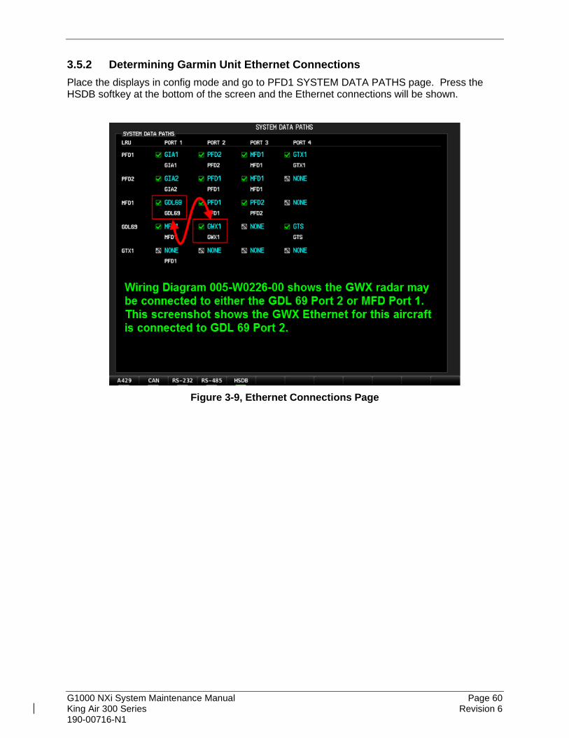
G1000 NXi System Maintenance Manual Page 60 King Air 300 Series Revision 6 190-00716-N1
3.5.2 Determining Garmin Unit Ethernet Connections Place the displays in config mode and go to PFD1 SYSTEM DATA PATHS page. Press the HSDB softkey at the bottom of the screen and the Ethernet connections will be shown.
Figure 3-9, Ethernet Connections Page

G1000 NXi System Maintenance Manual Page 61 King Air 300 Series Revision 6 190-00716-N1
3.5.3 Determining if Autopilot ESP is Installed To check if the aircraft has ESP installed, go to the MFD Aux - System Setup page and press the “Setup 2” softkey at the bottom of the screen. If the “Stability and Protection” field is present, the aircraft has ESP installed. If the field is not present, the aircraft does not have ESP installed.
Figure 3-10, ESP Status Field

G1000 NXi System Maintenance Manual Page 62 King Air 300 Series Revision 6 190-00716-N1
3.6 Configuration Checklist This sheet should be completed and maintained with the aircraft permanent records. Some loader card options are not shown here if they are not used for initial 300 Series software load. Date: Aircraft Make: Aircraft Registration: Aircraft Serial #: Loader Card Version:
01) Baseline
(One selection only) GIA 63W, GEA 71, GMA 1347D (See Note 1) GIA 63W, GEA 71, GMA 1360D (See Note 2) GIA 64, GEA 71B, GMA 1360
03) 300 Series Engine-Prop
(One selection only)
King Air 300 PT6A-60 Hartzell 4-Blade King Air 300 PT6A-60 Hartzell (Raisbeck) 4-Blade King Air 300 PT6A-60 Hartzell (Raisbeck) 5-Blade King Air 300 PT6A-67A Hartzell 5-Blade (Blackhawk) King Air B300 PT6A-60 Hartzell 4-Blade King Air B300 PT6A-60 Hartzell (Raisbeck) 4-Blade King Air B300 PT6A-60 Hartzell (Raisbeck) 5-Blade King Air B300 PT6A-67 MT 5 Blade King Air B300 PT6A-60A Heavyweight Configuration King Air B300 PT6A-67A Heavyweight Configuration
04) AHRS-Air Data
(Choose either the GSU 75B option or two selections for GRS and GDC combination)
King Air - GDC 7400 ADC King Air - GRS 7800 AHRS and GMU 44
Magnetometer King Air - GSU 75B ADAHRS and GMU 44
Magnetometer
05) Autopilot
(One selection only)
King Air 300 Series GFC700 - ESP Installation (No AOA)
King Air 300 Series GFC700 - Non ESP Installation King Air B300 Series GFC700 - ESP Installation (No
AOA) King Air B300 Series GFC700 - Non ESP Installation
06) Garmin Transponders
(One selection only for Garmin transponders, no selection if Rockwell Collins TDR94D transponders installed)
King Air - Dual GTX 33 Transponders and No GTS Unit Installed
King Air - Dual GTX 33 Transponders With GTS Unit Installed
King Air - Dual GTX 3000 Transponders With GTS Processor TCAS II
King Air – Dual GTX 3000 Transponders With Collins TTR-920/4000
King Air - Dual GTX 335R Transponders and No GTS Unit Installed
King Air - Dual GTX 335R Transponders With GTS Unit Installed
King Air - GTX 345R and 33 Transponders and No Active Traffic System
King Air - GTX 345R and 33 Transponders With GTS Unit Installed
King Air - GTX 345R and 33 Transponders With SkyWatch 429 Traffic
King Air - GTX 345R and 33 Transponders With Honeywell 429 Traffic
King Air - GTX 345R and 335R Transponders and No Active Traffic System
King Air - GTX 345R and 335R Transponders With GTS Unit Installed
King Air - GTX 345R and 335R Transponders With SkyWatch 429 Traffic
King Air - GTX 345R and 335R Transponders With Honeywell 429 Traffic
07) Connext - SXM
(Multiple selections possible)
King Air - GDL69A Legacy King Air - GDL69A SXM King Air - GDL59 Stand Alone (Connected to GDL 69) King Air - GDL59 Stand Alone (Connected to PFD2) King Air - GSR56 Stand Alone, Voice/SMS/Connext King Air - GSR56 and GDL59 (GDL 59 connected to
GDL69), Voice/SMS/Connext King Air - GSR56 and GDL59 (GDL 59 connected to
PFD2), Voice/SMS/Connext Enable Flight Stream 510 Disable Flight Stream 510
08) Radar
(Up to two selections possible)
King Air - GRA 5500 Radar Altimeter King Air - GWX 68 (Connected to GDL69) King Air - GWX 68 (Connected to MFD) King Air - GWX 70 (Connected to GDL69) King Air - GWX 70 (Connected to MFD)

G1000 NXi System Maintenance Manual Page 63 King Air 300 Series Revision 6 190-00716-N1
King Air - GWX 75 (Connected to GDL69) King Air - GWX 75 (Connected to MFD)
09) Garmin Traffic Systems
(One selection if GTS installed or skip if using third party traffic device)
King Air - GTS 820 TAS Traffic System (Connected to GDL69)
King Air - GTS 850 TCAS I Traffic System (Connected to GDL69)
King Air - GTS Traffic Processor TAS/TCAS I (Connected to GDL69), No GTX 345R
King Air - GTS Traffic Processor TAS/TCAS I (Connected to GDL69), With GTX 345R
King Air - GTS Traffic Processor TAS/TCAS I (Connected to PFD1), No GTX 345R
King Air - GTS Traffic Processor TAS/TCAS I (Connected to PFD1), With GTX 345R
King Air - GTS Traffic Processor TCAS II (Connected to GDL69)
King Air - GTS Traffic Processor TCAS II (Connected to PFD1)
10) Garmin Feature Support
(Multiple selections possible if installing TAWS-A)
King Air - TAWS-A Support1 King Air - TAWS-A Voice Callout Installation Option3 King Air - TAWS-A Voice No Callout Installation
Option2 Activate Garmin FlightCharts Only (Disables Dual
Charts and Chartview, if previously installed)
11) Non-Garmin Options
(Multiple selections possible)
King Air - ADF Option King Air - DME Option King Air - FDR with GSD Option King Air - FDR with GIA64 Option King Air - RAD ALT Option (429 Interface) King Air - Non-Garmin TCAS II System Option King Air - Traffic System Option (429 Interface), No
GTX 345R King Air - V1 Airspeed Option King Air - BLR Winglet STC (300 Series only) King Air - Lightning System Option King Air – G1000 FAST Option – NXi King Air – AUX COM Support Option King Air – Indep AUX COM Support Option
Unlock Card Options
(Multiple selections possible)
TAWS-B (010-00330-51) ChartView Only (010-00330-50) Synthetic Vision (010-00330-55) TAWS-A (010-00330-56) Enhanced AFCS (010-00330-5A) GTS Traffic TAS to TCAS I (010-00330-A1) GTS Traffic TAS to TCAS II (010-00330-A2)
GTS Traffic TCAS I to TCAS II (010-00330-A3) Search and Rescue (010-00330-59) Surface Watch (010-00330-KA) GWX 70 Turbulence Detection (010-00330-J3) GWX 70 Ground Clutter Suppression (010-00330-J4) GWX 75 Turbulence Detection and Ground Clutter
Suppression (010-00330-J9) Dual Charts (010-00330-KB)
Notes: 1 This selection configures the TAWS-A gear and flap
messages. An unlock card is still required to unlock feature after loading this file.
2 Disables 1, 2, 3, and 4 hundred foot callouts if desired. 3 Enables 1, 2, 3, and 4 hundred foot callouts if desired.
Note 1 – GIA 63W units with part numbers 011-01105-01 were previously approved for pre-NXi installations on the King Air 300 series aircraft per MDL 005-00421-00, Revision 19 and earlier. Now these part numbers are approved for use with the Garmin NXi system post Revision 19.
Note 2 – The GMA 1360D replaces the GMA 1347D and requires an optional GDL 69 to be installed. Note 1 still applies for this option.

G1000 NXi System Maintenance Manual Page 64 King Air 300 Series Revision 6 190-00716-N1
3.7 G1000 Software/Configuration Procedure This section summarizes the procedures required to load software and configuration files to the G1000. It is intended to work as a central guide for technicians to use while performing maintenance on the aircraft. In sections of this manual where software is required to be reloaded, these sections will make reference back to this section for instructions. The technician should use proper judgment regarding the context of maintenance required while following this section. The following diagram depicts an overview of the software/configuration sequence for the G1000 system. This applies mostly to a new G1000 system software installation by Service Bulletin and is for informative purposes only.
GDU 1050A PFDs / GDU 1550 MFD Software LoadSoftware is first loaded to the MFD and PFDs. From the factory, G1000 units do not contain useable software or configuration settings. Load software to PFD2
first then MFD and finally to PFD1.
G1000 System Upload SelectionAfter software is loaded to the MFD and PFDs, the displays should be placed in
configuration mode. Using PFD1, the technician goes to the System Upload page. From the System Upload page, software files are selected to create an
automated profile to load. Once all desired files are checked, the G1000 automatically loads the selected files in the correct sequence to the LRUs.
G1000 System Software VerificationAfter software is loaded to the system, the technician verifies that each LRU
reports the correct version and software part number.
G1000 System Configuration Upload SelectionFollowing G1000 system software upload and verification, the aircraft specific configuration files, as defined in the general arrangement drawing are loaded.
The aircraft general arrangement drawing will define the configuration files appropriate to the specific aircraft serial number, STC modifications and
applicable AFMS.
G1000 Configuration VerificationAfter system configuration files are loaded, the technician verifies that the
correct configuration on the Airframe Configuration page.
Figure 3-11, Software/Configuration Overview

G1000 NXi System Maintenance Manual Page 65 King Air 300 Series Revision 6 190-00716-N1
3.8 System Software and Configuration Load 3.8.1 System Power Up
Apply power to the G1000 system by connecting external power to the aircraft to energize the aircraft and avionics electrical busses. DO NOT RELY ON THE AIRCRAFT BATTERY TO LOAD SOFTWARE. DO NOT USE A BATTERY CHARGER AS AN EXTERNAL POWER SOURCE DUE TO ELECTRICAL NOISE IT MAY INJECT IN THE G1000 SYSTEM. Power loss during a software upgrade may cause a LRU to become corrupted and unresponsive requiring replacement. Remove power only when told to do so in the procedure.
3.8.2 GIA 63W part number 011-01105-01 Boot Block GIA 64E or GIA 63W part number 011-01105-20 are installed, skip to paragraph 3.8.3.
NOTE
For the GIA 63W part number 011-01105-01 only, Boot Block software is required to be installed prior to loading the GIA system software contained on the baseline loader card. If not loaded prior, the G1000 NXi system will not be able to identify the GIA 63W as a target LRU when attempting to load its system software and configuration and a failure will occur.
3.8.2.1 Downloading the GIA 63W Boot Block Software Image to SD Card The GIA 63W Boot Block software image is an executable self-extracting file which builds the correct file structure onto an SD card. To obtain the current file follow the procedures outlined below.
NOTE
In order to create a King Air 300 Series system loader card, the installer completing these procedures must be an authorized Garmin King Air Service Center to gain access to the necessary data via the Garmin website. Refer to the GA drawing listed for the correct part number of the GIA Boot Block loader card image that shall be downloaded.
1. Go to www.garmin.com and click on the Dealer Resource Center link in the lower portion of the home page. Enter your Garmin Dealer username and password.
2. Select Support button and Software Downloads from the drop-down menu. 3. In the Product Name or Part Number field enter “ GIA 63W” and wait for the drop-
down list with various aircraft types to appear. 4. Click on “GIA 63W (010-00386-00)” then click on the Search button.

G1000 NXi System Maintenance Manual Page 66 King Air 300 Series Revision 6 190-00716-N1
5. Click on the Select Action button adjacent to the “GIA 63W Boot Block Loader Version 6.10” line item.
6. Choose Download to save the file to the local hard drive. 7. After the file is downloaded, insert a blank (empty) SD card into the card reader. 8. Double-click the .exe file that was downloaded onto the local hard drive and follow the
on-screen directions for downloading the GIA boot block files to the SD card 9. The program will extract the files to the SD card. 10. Once successfully completed a prompt will appear, click Finish to close the program. 11. The SD card can then be removed from the computer and is ready to be inserted into
the top slot of PFD1.
3.8.2.2 GIA 63W Boot Block Loading the Software Follow this procedure to load the boot block software to GIA1 and GIA2. 1. Remove the Garmin database cards from the bottom slots of PFD1, MFD and PFD2 if
present. 2. Insert the GIA Boot Block loader card into the top SD card slot on PFD1. 3. Start the G1000 NXi system in configuration mode 4. On PFD 1, go to the SYSTEM UPLOAD page using the small FMS knob. 5. Push in the PFD 1 FMS knob to activate the cursor in the Group field, if not already active
from the previous section. Rotate the small FMS knob to highlight “GIA 63W Boot Block” in the drop-down menu and press the ENT key to select it.
6. Once “GIA 63W Boot Block” is selected, the cursor moves to the ITEM window. Rotate the small FMS knob to activate the drop-down menu. Highlight ‘GIA 63W Boot Block’ and press the ENT key. The PRODUCT field will then populate.
7. Press the Load softkey. 8. Monitor the loading progress and verify the software load completes without errors as
indicated by the following: 9. Green “PASS” or White “N/A” in all Configuration and Software columns. 10. “Upload Complete………….COMPLETE” in the summary box. 11. Press the ENT key to acknowledge the “Upload Complete” box. 12. Remove the GIA Boot Block loader card from the top SD card slot of PFD1 and proceed to
section 3.8.3 below to load the remaining baseline software and configuration files.
3.8.3 MFD & PFD Software Load
3.8.3.1 MFD & PFD Software Load (Software Version 2286.05 and Earlier) 1. Open the MFD, PFD 1 (PRI), PFD 1 (SEC), and PFD 2 circuit breakers. 2. Remove Garmin database cards from bottom slots of PFD1, MFD, and PFD2 if present. 3. Insert the software loader card into PFD2 top card slot. 4. Turn on Avionics electrical busses. 5. Close the PFD2 circuit breaker.

G1000 NXi System Maintenance Manual Page 67 King Air 300 Series Revision 6 190-00716-N1
6. When the “DO YOU WANT TO UPDATE SYSTEM FILES?” prompt appears, press the YES softkey.
7. After the new GDU software is loaded to PFD2, a “DO YOU WANT TO UPDATE THE
SPLASH SCREEN?” prompt will appear. Press the YES softkey.
8. When complete, the PFD2 starts in configuration mode displaying the “System Status”
page. Open PFD2 circuit breaker. 9. Remove the loader card from PFD2 and insert it into the top card slot on the MFD. 10. Repeat Steps 5 through 8 for the MFD using the MFD circuit breaker. The MFD does not
have an ENT key, so instead use softkey #12 for ENT when stated above. 11. When MFD update is complete, open the MFD circuit breaker, remove the loader card
from the MFD and insert it into the PFD1 top card slot. 12. Repeat Steps 5 through 8 for PFD1 using the PFD (PRI) circuit breaker. When
complete, leave PFD1 on with the loader card remaining in the top card slot. 13. Start the MFD and PFD2 in configuration mode by pressing and holding the ENT key or
softkey #12 when closing the circuit breakers. Release the key when the words “INITIALIZING SYSTEM” appear on the screen.
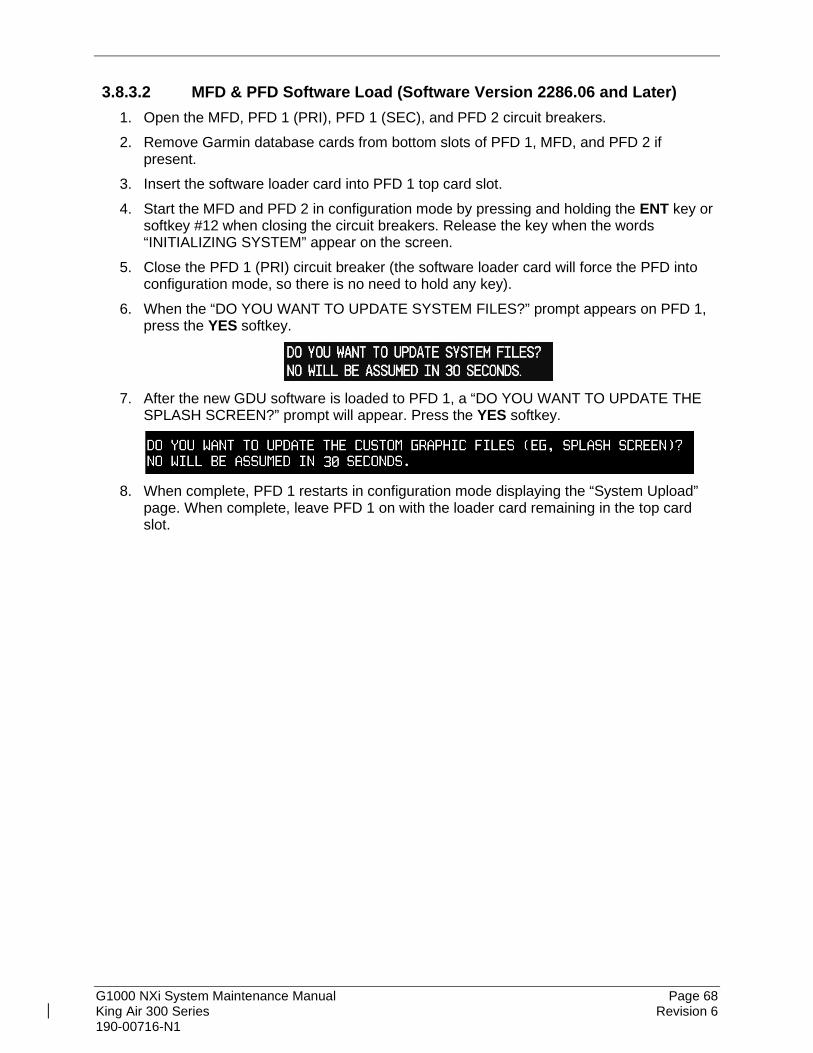
G1000 NXi System Maintenance Manual Page 68 King Air 300 Series Revision 6 190-00716-N1
3.8.3.2 MFD & PFD Software Load (Software Version 2286.06 and Later) 1. Open the MFD, PFD 1 (PRI), PFD 1 (SEC), and PFD 2 circuit breakers. 2. Remove Garmin database cards from bottom slots of PFD 1, MFD, and PFD 2 if
present. 3. Insert the software loader card into PFD 1 top card slot. 4. Start the MFD and PFD 2 in configuration mode by pressing and holding the ENT key or
softkey #12 when closing the circuit breakers. Release the key when the words “INITIALIZING SYSTEM” appear on the screen.
5. Close the PFD 1 (PRI) circuit breaker (the software loader card will force the PFD into configuration mode, so there is no need to hold any key).
6. When the “DO YOU WANT TO UPDATE SYSTEM FILES?” prompt appears on PFD 1, press the YES softkey.
7. After the new GDU software is loaded to PFD 1, a “DO YOU WANT TO UPDATE THE
SPLASH SCREEN?” prompt will appear. Press the YES softkey.
8. When complete, PFD 1 restarts in configuration mode displaying the “System Upload”
page. When complete, leave PFD 1 on with the loader card remaining in the top card slot.

G1000 NXi System Maintenance Manual Page 69 King Air 300 Series Revision 6 190-00716-N1
3.8.4 01) Baseline Software and Configuration Load
IMPORTANT If the aircraft being modified has incorporated any modifications beyond factory configuration that effect engine or airspeed limitations, your configuration may not be supported at this time. It is the responsibility of the installer to ensure compatibility with existing modifications. Do not allow power to be removed from the system when loading software. Remove power only when instructed by the following procedures. As a general rule, all displays should be in the same mode (configuration or normal) unless instructed otherwise. Follow the order of software and configuration loading, do not skip or rearrange steps. Do not operate or turn off MFD and/or PFD2 while loading software and configuration files unless specifically instructed to do so. A failed or cancelled load may result. If an incorrect configuration file is loaded at any time during this procedure, STOP and start the configuration load over at Step 2 in this Section.
1. Ensure all avionics circuit breakers are closed and the G1000 system is fully powered. 2. On PFD1, go to the SYSTEM UPLOAD page using the small FMS knob. 3. Push in the PFD1 FMS knob to activate the cursor in the Group field. Rotate the small
FMS knob to activate the drop-down menu. Rotate the small FMS knob to highlight “01) Baseline” in the drop-down menu and press the ENT key to select it.
4. Once “01) Baseline” is selected, the cursor moves to the ITEM window. Rotate the small FMS knob to activate the drop-down menu. Highlight the appropriate baseline configuration, then press the ENT key to select it. The PRODUCT field will then populate.

G1000 NXi System Maintenance Manual Page 70 King Air 300 Series Revision 6 190-00716-N1
NOTES The PRODUCT window displays information regarding each G1000 LRU. The LRU column depicts the reported software version of the LRU (may be blank if PFD1 cannot communicate with the unit yet until after config files are loaded). The CARD VERS column shows the LRU software version stored on the Loader Card. The SOFTWARE column may or may not have all boxes checked automatically. For the initial software load in the system all software boxes should be checked to load all files. This is done by pressing the CHK ALL softkey when instructed below. The CONFIGURATION column defaults to having all unit configuration boxes checked. The hardware serial number is used to determine appropriate software for the GIA COM, GIA NAV, GMU 44, and GSA 8X units. Until the system configuration loads sufficiently to access and read these units, they may show a “INV” invalid status under the LRU VERS and CARD VERS columns with up to two line items per item (representing different hardware configurations). After the configuration files are loaded, the units will update and remove the “INV” status and will load automatically.
5. Press the CHK All softkey. 6. Press the Load softkey. 7. Monitor the loading progress and verify the software load completes without errors as
indicated by the following:
• Green “PASS” or White “N/A” in all Configuration and Software columns.
• “Upload Complete………….COMPLETE” in the summary box. 8. Press the ENT key to acknowledge the “Upload Complete” box.
3.8.5 03) 300 Series Engine-Prop Software and Configuration Load Follow this procedure to configure the airframe type.
1. Move the cursor to the Group window and rotate FMS inner knob to display drop down menu. Highlight “03) 300 Series Engine-Prop” and press the ENT key to select it.
2. The cursor should automatically move to the ITEM window. Rotate the small FMS knob to highlight the appropriate airframe, engine, and prop combination that was checked on the Configuration checklist in Section 3.6, in the 03) 300 Series Engine-Prop checklist group and press the ENT key to select it.
3. Press the CHK All softkey. 4. In the PRODUCT window, move the cyan selection box down with the large FMS knob
to highlight the “CARD COPY” configuration check box if present. Press the ENT key to uncheck the configuration check box. If the “CARD COPY” configuration check box is not present, move to Step 5.
5. Press the Load softkey.

G1000 NXi System Maintenance Manual Page 71 King Air 300 Series Revision 6 190-00716-N1
NOTE Not all propellers are available for selection with each airframe and engine configuration. Only those props that are approved for installation on a particular airframe/engine are available in the drop down selection window.
6. Monitor the loading progress and verify the software load completes without errors as indicated by the following:
• Green “PASS” or White “N/A” in all Configuration and Software columns.
• “Upload Complete………….COMPLETE” in the summary box. 7. Press the ENT key to acknowledge the “Upload Complete” box.
3.8.6 04) AHRS – Air Data Software and Configuration Load Follow this procedure to configure the AHRS, Air Data, or ADAHRS units in the aircraft.
1. Move the cursor to the Group window and rotate FMS inner knob to display drop down menu. Highlight “04) AHRS – Air Data” and press the ENT key to select it.
2. In the ITEM window, rotate the small FMS knob to highlight the first item that was checked on the Configuration checklist in Section 3.6 in the 04) AHRS-Air Data checklist group and press the ENT key to select it.
3. Press the CHK All softkey. 4. In the PRODUCT window, move the cyan selection box down with the large FMS knob
to highlight the “CARD COPY” configuration check box if present. Press the ENT key to uncheck the configuration check box. If the “CARD COPY” configuration check box is not present, move to the next step.
5. Press the Load softkey. 6. Monitor the loading progress and verify the software load completes without errors as
indicated by the following:
• Green “PASS” in the Configuration and Software columns for each item loaded.
• “Upload Complete………….COMPLETE” in the summary box. 7. Press the ENT key to acknowledge the “Upload Complete” box. 8. If two selections were made for this section on the Configuration checklist (one AHRS
and one ADC), repeat steps 2-7 to load the second file.
3.8.7 05) Autopilot Software and Configuration Load Follow this procedure to configure the autopilot type and GSM servo mounts installed.
1. Move the cursor to the Group window and rotate FMS inner knob to display drop down menu. Highlight “05) Autopilot” and press the ENT key to select it.
2. In the ITEM window, rotate the small FMS knob to highlight the first item that was checked on the Configuration checklist in Section 3.6 in the 05) Autopilot checklist group and press the ENT key to select it.
3. Press the CHK All softkey.

G1000 NXi System Maintenance Manual Page 72 King Air 300 Series Revision 6 190-00716-N1
4. In the PRODUCT window, move the cyan selection box down with the large FMS knob to highlight the “CARD COPY” configuration check box if present. Press the ENT key to uncheck the configuration check box. If the “CARD COPY” configuration check box is not present, move to the next step. Press the ENT key to uncheck the configuration check box.
5. Press the Load softkey. 6. Monitor the loading progress and verify the software load completes without errors as
indicated by the following:
• Green “PASS” in the Configuration and Software columns for each item loaded.
• “Upload Complete………….COMPLETE” in the summary box. 7. Press the ENT key to acknowledge the “Upload Complete” box. 8. Rotate the large FMS knob to highlight the ITEM window and select the second file on
the Configuration checklist. Repeat steps 2-7 to load the second file.
3.8.8 06) Garmin Transponders Software and Configuration Load Follow this procedure to configure the Garmin transponders.
1. Rotate the large FMS knob until the Group field is highlighted, rotate the small FMS knob to activate the drop down menu. Rotate the small FMS knob and select “06) Garmin Transponders” and press the ENT key to select it.
2. In the ITEM window, rotate the small FMS knob to highlight the item that was checked on the Configuration checklist in Section 3.6 in the 06) Garmin Transponders checklist group and press the ENT key to select it.
3. Press the CHK All softkey. 4. In the PRODUCT window, move the cyan selection box down with the large FMS knob
to highlight the “CARD COPY” configuration check box if present. Press the ENT key to uncheck the configuration check box. If the “CARD COPY” configuration check box is not present, move to the next step. Press the ENT key to uncheck the configuration check box.
5. Press the Load softkey. 6. Monitor the loading progress and verify the software load completes without errors as
indicated by the following:
• Green “PASS” in the Configuration and Software columns for each item loaded.
• “Upload Complete………….COMPLETE” in the summary box. 7. Press the ENT key to acknowledge the “Upload Complete” box.
3.8.9 07) Connext –SXM Software and Configuration Load Follow this procedure to configure FS 510, GDL69A, GDL59, and GSR 56 options if installed.
1. Rotate the large FMS knob until the Group field is highlighted, rotate the small FMS knob to activate the drop down menu. Rotate the small FMS knob and select “07) Connext - SXM” and press the ENT key to select it.

G1000 NXi System Maintenance Manual Page 73 King Air 300 Series Revision 6 190-00716-N1
2. In the ITEM window, rotate the small FMS knob to highlight the first item that was checked on the Configuration checklist in Section 3.6 in the 07) Connext - SXM checklist group and press the ENT key to select it.
3. Press the CHK All softkey. 4. In the PRODUCT window, move the cyan selection box down with the large FMS knob
to highlight the “CARD COPY” configuration check box if present. Press the ENT key to uncheck the configuration check box. If the “CARD COPY” configuration check box is not present, move to the next step. Press the ENT key to uncheck the configuration check box.
5. Press the Load softkey. 6. Monitor the loading progress and verify the software load completes without errors as
indicated by the following:
• Green “PASS” in the Configuration and Software columns for each item loaded.
• “Upload Complete………….COMPLETE” in the summary box. 7. Press the ENT key to acknowledge the “Upload Complete” box. 8. If multiple selections were made for this section on the Configuration checklist, repeat
steps 2-7 to load each additional item on the Configuration checklist. If only one selection was made, continue to the next section.
3.8.10 08) Radar Software and Configuration Load Follow this procedure to configure GWX68, GWX 70, or GWX 75 and GRA 5500 if installed.
1. Rotate the large FMS knob until the Group field is highlighted, rotate the small FMS knob to activate the drop down menu. Rotate the small FMS knob and select “08) Radar” and press the ENT key to select it.
2. In the ITEM window, rotate the small FMS knob to highlight the first item that was checked on the Configuration checklist in Section 3.6 in the 08) Radar checklist group and press the ENT key to select it.
3. Press the CHK All softkey. 4. In the PRODUCT window, move the cyan selection box down with the large FMS knob
to highlight the “CARD COPY” configuration check box if present. Press the ENT key to uncheck the configuration check box. If the “CARD COPY” configuration check box is not present, move to the next step. Press the ENT key to uncheck the configuration check box.
5. Press the Load softkey. 6. Monitor the loading progress and verify the software load completes without errors as
indicated by the following:
• Green “PASS” in the Configuration and Software columns for each item loaded.
• “Upload Complete………….COMPLETE” in the summary box. 7. Press the ENT key to acknowledge the “Upload Complete” box. 8. If two selections were made for this section on the Configuration checklist, repeat steps
2-7 to load the second item.

G1000 NXi System Maintenance Manual Page 74 King Air 300 Series Revision 6 190-00716-N1
3.8.11 09) Garmin Traffic Systems Software and Configuration Load Follow this procedure to configure Garmin Traffic Systems if installed.
NOTE The G1000 can only be configured for TIS or TAS/TCAS but not both. Performing this procedure will automatically disable the TIS function. Configuration of the GTS Processor will require entering the aircraft registration number into the unit using Section 3.10 “Aircraft Registration Number Entry”.
1. Rotate the large FMS knob until the Group field is highlighted, rotate the small FMS knob
to activate the drop down menu. Rotate the small FMS knob and select “09) Garmin Traffic Systems” and press the ENT key to select it.
2. In the ITEM window, rotate the small FMS knob to highlight the item that was checked on the Configuration checklist in Section 3.6 in the 09) Garmin Traffic Systems checklist group and press the ENT key to select it.
3. Press the CHK All softkey. 4. In the PRODUCT window, move the cyan selection box down with the large FMS knob
to highlight the “CARD COPY” configuration check box if present. Press the ENT key to uncheck the configuration check box. If the “CARD COPY” configuration check box is not present, move to the next step. Press the ENT key to uncheck the configuration check box.
5. Press the Load softkey. 6. Monitor the loading progress and verify the software load completes without errors as
indicated by the following:
• Green “PASS” in the Configuration and Software columns for each item loaded.
• “Upload Complete………….COMPLETE” in the summary box. 7. Press the ENT key to acknowledge the “Upload Complete” box.
3.8.12 10) Garmin Feature Support Configuration Load This section applies only to installations with the TAWS-A option. The procedures outlined in this section must be followed to load the necessary configuration files required to enable TAWS-A gear and flap messages. A TAWS-A enablement card is also required for this option.
NOTE TAWS-A Voice No Callout applies only to installations with the TAWS-A option. If TAWS-A voice callouts (400, 300, 200, and 100 feet) are not desired, follow the procedures outlined in this section to load the necessary configuration files to disable TAWS-A voice callouts.
1. Rotate the large FMS knob until the Group field is highlighted, rotate the small FMS knob to activate the drop down menu. Rotate the small FMS knob and select “10) Garmin Feature Support” and press the ENT key to select it.
2. In the ITEM window, rotate the small FMS knob to highlight the first item (King Air – TAWS-A Support) that was checked on the Configuration checklist in Section 3.6 in the 10) Garmin Feature Support checklist group and press the ENT key to select it.

G1000 NXi System Maintenance Manual Page 75 King Air 300 Series Revision 6 190-00716-N1
3. In the PRODUCT window, move the cyan selection box down with the large FMS knob to highlight the “CARD COPY” configuration check box if present. Press the ENT key to uncheck the configuration check box. If the “CARD COPY” configuration check box is not present, move to the next step. Press the ENT key to uncheck the configuration check box.
4. Press the LOAD softkey. 5. Monitor the loading progress and verify the software load completes without errors as
indicated by the following:
• Green “PASS” in the Configuration and Software columns for each item loaded.
• “Upload Complete………….COMPLETE” in the summary box. 6. Press the ENT key to acknowledge the “Upload Complete” box. 7. If TAWS-A Voice No Callout option is desired, repeat steps 2-6 to load the “King Air -
TAWS-A Voice No Callout Installation Option” file.
3.8.13 11) Non Garmin Options Configuration Load Follow this procedure to configure non-Garmin items if installed.
1. Rotate the large FMS knob until the GROUP field is highlighted, rotate the small FMS knob to activate the drop down menu. Rotate the small FMS knob and select “11) Non Garmin Items” and press the ENT softkey.
2. In the ITEM window, rotate the small FMS knob to highlight the first item that was checked on the Configuration checklist in section 3.6 in the 11) Non-Garmin Options checklist group and press the ENT key to Select it.
3. In the PRODUCT window, move the cyan selection box down with the large FMS knob to highlight the “CARD COPY” configuration check box. Press the ENT key to uncheck the configuration check box.
4. Press the Load softkey. 5. Monitor the loading progress and verify the software load completes without errors as
indicated by the following:
• Green “PASS” in the Configuration and Software columns for each item loaded.
• “Upload Complete………….COMPLETE” in the summary box. 6. Press the ENT key to acknowledge the “Upload Complete” box. 7. If multiple selections were made for this Section on the Configuration checklist, repeat
steps 2-6 to load each additional option.
3.8.14 Save Configuration 9. Press the UPDT CFG softkey at the bottom of the SYSTEM UPLOAD page. 10. Press the ENT key to select YES in the pop-up window to start the update. 11. When the config module update is done, press the ENT key to select OK in the pop-up
window to close it. 12. Open PFD 1 circuit breaker, remove the software loader card and continue to the next
Section.

G1000 NXi System Maintenance Manual Page 76 King Air 300 Series Revision 6 190-00716-N1
3.9 Feature Enablement This section describes how to unlock or enable optional features. The installer will only load the sections for the features they require. For installing all feature enablement cards, PFD1, PFD2, and the MFD must be in configuration mode. The G1000 has various features that require the use of unlock/enable cards to activate the feature. Throughout this document these cards are generically referred to as ‘enablement cards’. In some cases, the actual label on the physical card may say ‘unlock’. If uncertain what SD Card to use, the technician must verify the card part number on the General Arrangement drawing prior to use to assure the correct feature is unlocked.
3.9.1 ChartView Feature Enablement Follow this procedure to activate the Jeppesen ChartView electronic charts that are provided as an option for this STC. The Garmin FliteCharts are provided and installed when the baseline display software is loaded. If this feature is loaded then the Garmin FliteCharts will be erased and the Jeppesen Chartview charts will be the only electronic charts available for display. If both FliteCharts and the Chartview charts are desired to be installed then use the dual charts enablement card identified in Section 3.9.2.
NOTES
The required ChartView databases are subscription-based and need to be procured by the installing agency from the Garmin or Jeppesen website. The ChartView database is not present in a new display.
1. Insert the ChartView Enablement card in the top slot of PFD1 and power on PFD1 in
configuration mode. 2. On PFD1, select the “System Upload” page using the small FMS knob. 3. Push in the FMS knob to activate the curser in the Group field. Rotate the small FMS
knob to highlight “Configuration Files” and press the ENT key to select it. 4. In the ITEM window, rotate the small FMS knob to highlight “Enable ChartView” and
press the ENT key to select it. 5. Press the Load softkey. 6. Monitor load progress. Verify software load completes without errors as indicated by the
following:
• Green “PASS” in the Configuration column for each item loaded.
• “Upload Complete………….COMPLETE” in the summary box. 7. Press the ENT key to acknowledge the “Upload Complete” box. 8. Open PFD1 circuit breaker and remove the ChartView enablement card.
3.9.2 Dual Charts Enablement Follow this procedure to enable the Dual Charts display feature. This enables the pilot to switch between Garmin FliteCharts and Jeppesen ChartView products on the MFD.

G1000 NXi System Maintenance Manual Page 77 King Air 300 Series Revision 6 190-00716-N1
1. Insert the Dual Charts Enablement card in the top slot of PFD1 and power on PFD1 in configuration mode.
2. On PFD1, select the “System Upload” page using the small FMS knob. 3. Push in the FMS knob to activate the curser in the Group field. Rotate the small FMS
knob to highlight “Enable_DualCharts” and press the ENT key to select it. 4. In the ITEM window, rotate the small FMS knob to highlight “Dual Charts Feature
Enable” and press the ENT key to select it. 5. Press the Load softkey. 6. Monitor load progress. Verify software load completes without errors as indicated by the
following:
• Green “PASS” in the Configuration column for each item loaded.
• “Upload Complete………….COMPLETE” in the summary box. 7. Press the ENT key to acknowledge the “Upload Complete” box. 8. Open PFD1 circuit breaker and remove the Dual Charts enablement card.
3.9.3 SurfaceWatch Feature Enablement Follow this procedure to enable the SurfaceWatch feature.
1. Insert the SurfaceWatch Enablement card in the top slot of PFD1 and power on PFD1 in configuration mode.
2. On PFD1, select the “System Upload” page using the small FMS knob. 3. Push in the FMS knob to activate the curser in the Group field. Rotate the small FMS
knob to highlight “Enable_SurfaceWatch” and press the ENT key to select it. 4. In the ITEM window, rotate the small FMS knob to highlight “SurfaceWatch Feature
Enable” and press the ENT key to select it. 5. Press the Load softkey. 6. Monitor load progress. Verify software load completes without errors as indicated by the
following:
• Green “PASS” in the Configuration column for each item loaded.
• “Upload Complete………….COMPLETE” in the summary box. 7. Press the ENT key to acknowledge the “Upload Complete” box. 8. Open PFD1 circuit breaker and remove the SurfaceWatch enablement card.
3.9.4 GWX 70 Radar Turbulence Detection Feature Enablement Follow this procedure to enable the GWX 70 Turbulence Detection feature.
1. Insert the GWX 70 Turbulence Detection Enablement card in the top slot of PFD1 and power on PFD1 in configuration mode.
2. On PFD1, select the “System Upload” page using the small FMS knob. 3. Push in the FMS knob to activate the curser in the Group field. Rotate the small FMS
knob to highlight “Enable_TD” and press the ENT key to select it.

G1000 NXi System Maintenance Manual Page 78 King Air 300 Series Revision 6 190-00716-N1
4. In the ITEM window, rotate the small FMS knob to highlight “GWX 70 Turbulence Detection Enable” and press the ENT key to select it.
5. Press the Load softkey. 6. Monitor load progress. Verify software load completes without errors as indicated by the
following:
• Green “PASS” in the Configuration column for each item loaded.
• “Upload Complete………….COMPLETE” in the summary box. 7. Press the ENT key to acknowledge the “Upload Complete” box. 8. Open PFD1 circuit breaker and remove the Turbulence Detection enablement card.
3.9.5 GWX 70 Ground Clutter Suppression Feature Enablement Follow this procedure to enable the GWX 70 Ground Clutter Suppression feature.
1. Insert the GWX 70 Ground Clutter Suppression Enablement card in the top slot of PFD1 and power on PFD1 in configuration mode.
2. On PFD1, select the “System Upload” page using the small FMS knob. 3. Push in the FMS knob to activate the curser in the Group field. Rotate the small FMS
knob to highlight “Enable_GCS” and press the ENT key to select it. 4. In the ITEM window, rotate the small FMS knob to highlight “GWX 70 Ground Clutter
Suppression Enable” and press the ENT key to select it. 5. Press the Load softkey. 6. Monitor load progress. Verify software load completes without errors as indicated by the
following:
• Green “PASS” in the Configuration column for each item loaded.
• “Upload Complete………….COMPLETE” in the summary box. 7. Press the ENT key to acknowledge the “Upload Complete” box. 8. Open PFD1 circuit breaker and remove the Ground Clutter Suppression enablement
card.
3.9.6 GWX 75 Turbulence Detection and Ground Clutter Suppression Feature Enablement Follow this procedure to enable the GWX 75 Turbulence Detection Ground Clutter Suppression feature.
1. Insert the GWX 75 Turbulence Detection and Ground Clutter Suppression Enablement card in the top slot of PFD1 and power on PFD1 in configuration mode.
2. Rotate the small FMS knob to highlight “Enable_TD_GCS” and press the ENT key to select it.
3. In the ITEM window, rotate the small FMS knob to highlight “Doppler, TD, GCS Enablement” and press the ENT key to select it.
4. Press the Load softkey.

G1000 NXi System Maintenance Manual Page 79 King Air 300 Series Revision 6 190-00716-N1
5. Monitor load progress. Verify software load completes without errors as indicated by the following:
• Green “PASS” in the Configuration column for each item loaded.
• “Upload Complete………….COMPLETE” in the summary box. 6. Press the ENT key to acknowledge the “Upload Complete” box. 7. Open PFD1 circuit breaker and remove the GWX 75 Turbulence Detection and Ground
Clutter Suppression enablement card.
3.9.7 TAWS-B Feature Enablement Follow this procedure to enable the TAWS Class B feature. If TAWS-A is required instead, go to Section 3.9.8.
1. Insert the TAWS-B Enablement card in the top slot of PFD1 and power on PFD1 in configuration mode.
2. On PFD1, select the “System Upload” page using the small FMS knob. 3. Push in the FMS knob to activate the curser in the Group field. Rotate the small FMS
knob to highlight “Configuration Files” and press the ENT key to select it. 4. In the ITEM window, rotate the small FMS knob to highlight “Enable TAWS” and press
the ENT key to select it. 5. Press the Load softkey. 6. Monitor load progress. Verify software load completes without errors as indicated by the
following: 7. Green “PASS” in the Configuration column for each item loaded. 8. “Upload Complete………….COMPLETE” in the summary box. 9. Press the ENT key to acknowledge the “Upload Complete” box. 10. Open PFD1 circuit breaker and remove the TAWS-B enablement card.
3.9.8 TAWS-A Enablement Follow this procedure to enable the TAWS Class A feature.
NOTES
Ensure that the King Air - TAWS-A Support Configuration file has been loaded per Section 3.8.12 and that a Radar Altimeter Option (King Air - GRA 5500 Radar Altimeter or King Air - RAD ALT Option (429 Interface)) Configuration file has been loaded.
1. Insert the TAWS-A Enablement card in the top slot of PFD1, power on PFD1 in configuration mode.
2. On PFD1, select the “System Upload” page using the small FMS knob. 3. Push in the FMS knob to activate the curser in the Group field. Rotate the small FMS
knob to highlight “Configuration Files” and press the ENT key to select it.

G1000 NXi System Maintenance Manual Page 80 King Air 300 Series Revision 6 190-00716-N1
4. In the ITEM window, rotate the small FMS knob to highlight “Enable TAWS-A” and press the ENT key to select it.
5. Press the Load softkey. 6. Monitor load progress. Verify software load completes without errors as indicated by the
following:
• Green “PASS” in the Configuration column for each item loaded.
• “Upload Complete………….COMPLETE” in the summary box. 7. Press the ENT key to acknowledge the “Upload Complete” box. 8. Open PFD1 circuit breaker and remove TAWS-A enablement card.
3.9.9 Synthetic Vision System Enablement Follow this procedure to enable the Synthetic Vision feature.
1. Insert the SVS Enablement card in the top slot of PFD1, power on PFD1 in configuration mode.
2. On PFD1, select the “System Upload” page using the small FMS knob. 3. Push in the FMS knob to activate the curser in the Group field. Rotate the small FMS
knob to highlight “Configuration Files” and press the ENT key to select it. 4. In the ITEM window, rotate the small FMS knob to highlight “Enable SVS Dual PFD”
and press the ENT key to select it. 5. Press the Load softkey. 6. Monitor load progress. Verify software load completes without errors as indicated by the
following:
• Green “PASS” in the Configuration column for each item loaded.
• “Upload Complete………….COMPLETE” in the summary box. 7. Press the ENT key to acknowledge the “Upload Complete” box. 8. Open PFD1 circuit breaker and remove SVS enablement card.
3.9.10 Enhanced AFCS (ESP) Enablement Follow this procedure to enable the Electronic Stability and Protection (ESP) feature.
NOTE
Ensure that the King Air 300 Series GFC700 - ESP Installation Configuration file has been loaded first.
1. Insert the Enhanced AFCS Enablement card in the top slot of PFD1, power on PFD1 in configuration mode.
2. On PFD1, select the “System Upload” page using the small FMS knob. 3. Push in the FMS knob to activate the curser in the Group field. Rotate the small FMS
knob to highlight “Enhanced AFCS” and press the ENT key to select it.

G1000 NXi System Maintenance Manual Page 81 King Air 300 Series Revision 6 190-00716-N1
4. In the ITEM window, rotate the small FMS knob to highlight “Enable Enhanced AFCS” and press the ENT key to select it.
5. Press the Load softkey. 6. Monitor load progress. Verify software load completes without errors as indicated by the
following:
• Green “PASS” in the Configuration column for each item loaded.
• “Upload Complete………….COMPLETE” in the summary box. 7. Press the ENT key to acknowledge the “Upload Complete” box. 8. Open PFD1 circuit breaker and remove Enhanced AFCS enablement card.
3.9.11 Search and Rescue Enablement Follow this procedure to enable the Search and Rescue (SAR) feature.
1. Insert the SAR Enablement card in the top slot of PFD1, power on PFD1 in configuration mode.
2. On PFD1, select the “System Upload” page using the small FMS knob. 3. Push in the FMS knob to activate the curser in the Group field. Rotate the small FMS
knob to highlight “Enhanced SAR” and press the ENT key to select it. 4. In the ITEM window, rotate the small FMS knob to highlight “Enhanced Search and
Rescue” and press the ENT key to select it. 5. Press the Load softkey. 6. Monitor load progress. Verify software load completes without errors as indicated by the
following:
• Green “PASS” in the Configuration column for each item loaded.
• “Upload Complete………….COMPLETE” in the summary box. 7. Press the ENT key to acknowledge the “Upload Complete” box. 8. Open PFD1 circuit breaker and remove SAR enablement card.
3.9.12 GTS TCAS I Enablement Follow this procedure to enable Garmin GTS TCAS I feature. If TCAS II is desired instead, go to Section 3.9.13.
1. Insert the TCAS I Enablement card in the top slot of PFD1, power on PFD1 in configuration mode.
2. On PFD1, select the “System Upload” page using the small FMS knob. 3. Push in the FMS knob to activate the curser in the Group field. Rotate the small FMS
knob to highlight “GTS Processor Enablement” and press the ENT key to select it. 4. In the ITEM window, rotate the small FMS knob to highlight “GTS Processor TAS to
TCAS I Enablement” and press the ENT key to select it. 5. Press the Load softkey. 6. Monitor load progress. Verify software load completes without errors as indicated by the
following:

G1000 NXi System Maintenance Manual Page 82 King Air 300 Series Revision 6 190-00716-N1
• Green “PASS” in the Configuration column for each item loaded.
• “Upload Complete………….COMPLETE” in the summary box. 7. Press the ENT key to acknowledge the “Upload Complete” box. 8. Open PFD1 circuit breaker and remove the Enhanced TCAS I enablement card.
3.9.13 GTS TCAS II Enablement Follow this procedure to enable the Garmin GTS TCAS II feature.
1. Insert the TCAS II Enablement card in the top slot of PFD1, power on PFD1 in configuration mode.
2. On PFD1, select the “System Upload” page using the small FMS knob. 3. Push in the FMS knob to activate the curser in the Group field. Rotate the small FMS
knob to highlight “GTS Processor Enablement” and press the ENT key to select it. 4. In the ITEM window, rotate the small FMS knob to highlight “GTS Processor TAS to
TCAS II Enablement” and press the ENT key to select it. 5. Press the Load softkey. 6. Monitor load progress. Verify software load completes without errors as indicated by the
following:
• Green “PASS” in the Configuration column for each item loaded.
• “Upload Complete………….COMPLETE” in the summary box. 7. Press the ENT key to acknowledge the “Upload Complete” box. 8. Open PFD1 circuit breaker and remove the Enhanced TCAS II enablement card.
3.9.14 Flight Stream 510 This file is designed to allow the installer to re-enable the Flight Stream 510 if it was previously disabled. This file is not required to enable Flight Stream 510 if it was not previously disabled. Flight Stream 510 is enabled by default in the baseline configuration.
1. Insert the software loader card in the top slot of PFD1, power on PFD1 in configuration mode.
2. Press the NO softkey (number 11 softkey) to acknowledge the following prompt.
3. On PFD1, select the “System Upload” page using the small FMS knob. 4. Push in the FMS knob to activate the curser in the Group field. Rotate the small FMS
knob to highlight “07) Connext - SXM” and press the ENT key to select it. 5. In the ITEM window, rotate the small FMS knob to highlight “Enable Flight Stream 510”
and press the ENT key to select it. 6. Press the CHK ALL softkey. 7. In the product window, move the cursor to highlight “CARD COPY”. Press the ENT key
to uncheck the configuration check box.

G1000 NXi System Maintenance Manual Page 83 King Air 300 Series Revision 6 190-00716-N1
8. Press the Load softkey. 9. Monitor load progress. Verify software load completes without errors as indicated by the
following:
• Green “PASS” in the Configuration column for each item loaded.
• “Upload Complete………….COMPLETE” in the summary box. 10. Press the ENT key to acknowledge the “Upload Complete” box. 11. Open PFD1 circuit breaker and remove the software loader card.
3.9.15 FliteCharts Enablement This file is designed to allow the installer to revert the Charts options back to the default FliteCharts setting if Dual Charts or ChartView features were previously enabled. This file is not required to enable FliteCharts if Dual Charts or ChartView were not previously enabled. FliteCharts is enabled by default in the baseline configuration.
1. Insert the software loader card in the top slot of PFD1, power on PFD1 in configuration mode.
2. Press the NO softkey (number 11 softkey) to acknowledge the following prompt.
3. On PFD1, select the “System Upload” page using the small FMS knob. 4. Push in the FMS knob to activate the curser in the Group field. Rotate the small FMS
knob to highlight “10) Garmin Feature Support” and press the ENT key to select it. 5. In the ITEM window, rotate the small FMS knob to highlight “Activate Garmin
FliteCharts Only (Disables Dual Charts and ChartView” and press the ENT key to select it.
6. Press the CHK ALL softkey. 7. In the product window, move the cursor to highlight “CARD COPY”. Press the ENT key
to uncheck the configuration check box. 8. Press the Load softkey. 9. Monitor load progress. Verify software load completes without errors as indicated by the
following:
• Green “PASS” in the Configuration column for each item loaded.
• “Upload Complete………….COMPLETE” in the summary box. 10. Press the ENT key to acknowledge the “Upload Complete” box. 11. Open PFD1 circuit breaker and remove the software loader card.
3.9.16 TAWS-A Voice Callout Enablement This file is designed to allow the installer to re-enable the 1, 2, 3, and 4 hundred foot callouts if the no voice callout option was loaded previously. This file is not required to enable the voice callouts if the no voice callout option was not loaded previously. The voice callouts are enabled by default in the baseline configuration.

G1000 NXi System Maintenance Manual Page 84 King Air 300 Series Revision 6 190-00716-N1
1. Insert the software loader card in the top slot of PFD1, power on PFD1 in configuration mode.
2. Press the NO softkey (number 11 softkey) to acknowledge the following prompt.
3. On PFD1, select the “System Upload” page using the small FMS knob. 4. Push in the FMS knob to activate the curser in the Group field. Rotate the small FMS
knob to highlight “10) Garmin Feature Support” and press the ENT key to select it. 5. In the ITEM window, rotate the small FMS knob to highlight “Activate Garmin
FliteCharts Only (Disables Dual Charts and ChartView” and press the ENT key to select it.
6. Press the CHK ALL softkey. 7. In the product window, move the cursor to highlight “CARD COPY”. Press the ENT key
to uncheck the configuration check box. 8. Press the Load softkey. 9. Monitor load progress. Verify software load completes without errors as indicated by the
following:
• Green “PASS” in the Configuration column for each item loaded.
• “Upload Complete………….COMPLETE” in the summary box. 10. Press the ENT key to acknowledge the “Upload Complete” box. 11. Open PFD1 circuit breaker and remove the software loader card.
3.9.17 B300 Heavyweight Configuration Enablement Follow this procedure to activate the B300 Heavyweight Configuration Enablement for this STC. If the King Air B300 PT6A-60A Heavyweight Configuration or King Air B300 PT6A-67A Heavyweight Configuration has been loaded for the 300 Series Engine Prop selection then this enablecard must be loaded to provide valid display of engine instruments. The engine instrument window will be red X’d until this enablement card is loaded. This enablement card should only be loaded when a B300 heavyweight configuration has been selected for the 300 Series Engine Prop selection group.
1. Insert the B300 Heavyweight Enablement card in the top slot of PFD1 and power on PFD1 in configuration mode.
2. On PFD1, select the “System Upload” page using the small FMS knob. 3. Push in the FMS knob to activate the curser in the Group field. Rotate the small FMS
knob to highlight “Enable_Heavyweight” and press the ENT key to select it. 4. In the ITEM window, rotate the small FMS knob to highlight “King Air B300
Heavyweight, Enablement” and press the ENT key to select it. 5. Press the Load softkey. 6. Monitor load progress. Verify software load completes without errors as indicated by the
following:

G1000 NXi System Maintenance Manual Page 85 King Air 300 Series Revision 6 190-00716-N1
• Green “PASS” in the Configuration column for each item loaded.
• “Upload Complete………….COMPLETE” in the summary box. 7. Press the ENT key to acknowledge the “Upload Complete” box. 8. Open PFD1 circuit breaker and remove the B300 Heavyweight enablement card.
3.9.18 POTS Handset Configuration Follow this procedure to enable a POTS handset if installed. Note that the GDL 59 Wi-Fi data link option must be loaded per Section 3.8.9 prior to loading the POTS handset configuration.
1. Power on PFD1 in configuration mode. 2. On the PFD1, select GDL page group using the large FMS knob. 3. Using the small FMS knob select the GDL 59 Configuration page. 4. Activate the cursor. Use the large FMS knob to select POTS CONNECTED in the PHONE
SETTINGS field. 5. Use the small FMS knob to select YES and press the ENT key. 6. After GDL 59 is configured, press the ENT key.
3.10 Aircraft Registration Number Entry NOTE
Steps to complete the aircraft registration entry are dependent on transponder equipment installed. Choose the appropriate procedure from Section 3.10.1 or 3.10.2 to complete the aircraft registration entry.
3.10.1 Equipped with Dual GTX 33s or GTX 3000s 1. Power on PFD1 in configuration mode. Select the AIRCRAFT CONFIGURATION page
on PFD1. 2. Activate the cursor to select the ”AIRCRAFT REGISTRATION” field and enter the
aircraft’s tail number. 3. For non-US “N” number aircraft registrations, rotate the large FMS knob to select the
“ICAO ADDRESS” and enter the aircraft’s 24 bit ICAO address. US “N” number aircraft registrations are automatically decoded and entered in this field, do not change the number.
4. If applicable, rotate the large FMS knob to select the “ICAO REGION” field and select the ICAO region. Otherwise, leave at “NONE”.
5. If applicable, rotate the large FMS knob to select the ”DOMAIN IDENTIFIER” field and enter the number. Otherwise, leave blank.
6. Rotate the large FMS knob to select the “VFR CODE” field and enter the desired code that will become active when the VFR key on a PFD is pressed.
7. For GTX 33 units only, press the Set GTX1 softkey and acknowledge the PFD1 prompt by pressing the ENT key. Repeat for the Set GTX2 softkey.
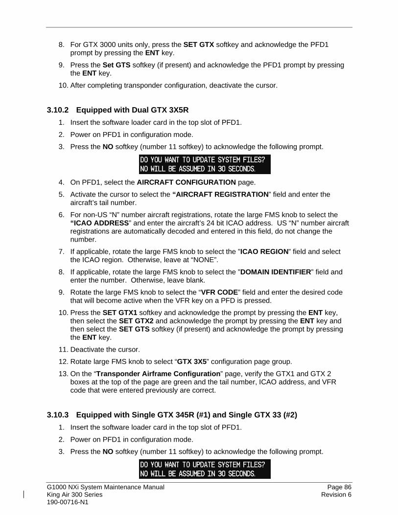
G1000 NXi System Maintenance Manual Page 86 King Air 300 Series Revision 6 190-00716-N1
8. For GTX 3000 units only, press the SET GTX softkey and acknowledge the PFD1 prompt by pressing the ENT key.
9. Press the Set GTS softkey (if present) and acknowledge the PFD1 prompt by pressing the ENT key.
10. After completing transponder configuration, deactivate the cursor.
3.10.2 Equipped with Dual GTX 3X5R 1. Insert the software loader card in the top slot of PFD1. 2. Power on PFD1 in configuration mode. 3. Press the NO softkey (number 11 softkey) to acknowledge the following prompt.
4. On PFD1, select the AIRCRAFT CONFIGURATION page. 5. Activate the cursor to select the “AIRCRAFT REGISTRATION” field and enter the
aircraft’s tail number. 6. For non-US “N” number aircraft registrations, rotate the large FMS knob to select the
“ICAO ADDRESS” and enter the aircraft’s 24 bit ICAO address. US “N” number aircraft registrations are automatically decoded and entered in this field, do not change the number.
7. If applicable, rotate the large FMS knob to select the ”ICAO REGION” field and select the ICAO region. Otherwise, leave at “NONE”.
8. If applicable, rotate the large FMS knob to select the ”DOMAIN IDENTIFIER” field and enter the number. Otherwise, leave blank.
9. Rotate the large FMS knob to select the “VFR CODE” field and enter the desired code that will become active when the VFR key on a PFD is pressed.
10. Press the SET GTX1 softkey and acknowledge the prompt by pressing the ENT key, then select the SET GTX2 and acknowledge the prompt by pressing the ENT key and then select the SET GTS softkey (if present) and acknowledge the prompt by pressing the ENT key.
11. Deactivate the cursor. 12. Rotate large FMS knob to select “GTX 3X5” configuration page group. 13. On the “Transponder Airframe Configuration” page, verify the GTX1 and GTX 2
boxes at the top of the page are green and the tail number, ICAO address, and VFR code that were entered previously are correct.
3.10.3 Equipped with Single GTX 345R (#1) and Single GTX 33 (#2) 1. Insert the software loader card in the top slot of PFD1. 2. Power on PFD1 in configuration mode. 3. Press the NO softkey (number 11 softkey) to acknowledge the following prompt.

G1000 NXi System Maintenance Manual Page 87 King Air 300 Series Revision 6 190-00716-N1
4. Select the AIRCRAFT CONFIGURATION page on PFD1. 5. Activate the cursor to select the ”AIRCRAFT REGISTRATION” field and enter the
aircraft’s tail number. 6. Rotate the large FMS knob to select the “ICAO ADDRESS” and enter the aircraft’s 24
bit ICAO address. 7. If applicable, rotate the large FMS knob to select the ”ICAO REGION” field and select
the ICAO region. Otherwise, leave at “NONE”. 8. If applicable, rotate the large FMS knob to select the ”DOMAIN IDENTIFIER” field and
enter the number. Otherwise, leave blank. 9. Rotate the large FMS knob to select the “VFR CODE” field and enter the desired code
that will become active when the VFR key on a PFD is pressed. 10. Press the Set GTX1 softkey and acknowledge the PFD1 prompt by pressing the ENT
key. Then Press the Set GTX2 softkey and acknowledge the PFD1 prompt by pressing the ENT key.
11. Press the Set GTS softkey (if present) and acknowledge the PFD1 prompt by pressing the ENT key.
12. Deactivate the cursor. 13. Rotate large FMS knob to select “GTX 3X5” configuration page group. 14. Rotate the small FMS knob to select “Transponder Airframe Configuration” page. 15. Verify the GTX1 box at the top of the page is green and the tail number, ICAO address,
and VFR code that were entered previously are correct.
3.11 Configuration Manager 1. On PFD1, rotate the large FMS knob to select “SYSTEM” configuration page group. 2. Rotate the small FMS knob to select Configuration Manager page. 3. Press the softkey labelled CNFM CFG on PFD1. 4. Press the ENT key on PFD1 to select OK when prompted to confirm configuration as
expected configuration. 5. Open MFD, PFD 1 (PRI), PFD 1 (SEC), and PFD 2 circuit breakers.
3.12 Splash Screen Loading Reference Section 3.8.3.2 for Splash Screen loading.
3.13 Clearing Default User Settings
1. Open MFD, PFD1 PRI, PFD1 SEC, and PFD2 circuit breakers. 2. While holding the CLR button on PFD1, close PFD1 PRI circuit breaker. 3. When prompted to clear user settings, select the YES softkey. 4. When user settings have been cleared appears on the screen, Open PFD1 PRI circuit
breaker.

G1000 NXi System Maintenance Manual Page 88 King Air 300 Series Revision 6 190-00716-N1
5. While holding the second key from the right side (#11 softkey) of the MFD, close the MFD circuit breaker.
6. When prompted to clear user settings, select the YES softkey. 7. When user settings have been cleared appears on the screen, open MFD circuit
breaker. 8. While holding the CLR button on PFD 2, close the PFD2 circuit breaker. 9. When prompted to clear user settings, select the YES softkey. 10. When user settings have been cleared appears on the screen, open PFD2 circuit
breaker.
3.14 Database Loading Follow this procedure to load the databases using the SD card method.
NOTE
It is recommended that the initial database load to the avionics be accomplished using the SD card method. However, at the installer’s discretion, the Flight Stream 510 and Garmin Pilot app may be used to load databases. Once initial databases are loaded, it is not recommended to alternate between methods when updating avionics databases. For example, if Flight Stream 510 is used for future database updates, reverting to the SD card method may introduce conflicting database versions when both it and the Flight Stream 510 card are installed. If a technician desires to use the SD card method, any databases on the Flight Stream 510 should first be deleted by formatting the Flight Stream 510 card.
1. Obtain the following databases from fly.garmin.com and install on a blank 16GB or larger
card, or by obtaining Garmin SD Card P/N 010-00474-50 which contains some of the databases below. Databases with an (*) asterisk are not included on the P/N 010-00474-50 SD card. If obtaining the databases from fly.garmin.com and using SD cards smaller than 16GB, you may need to use multiple cards (or reuse one) to load all the databases into the G1000 system.
a. Terrain (Worldwide, 4.9 Arc Second, TBD2 format) b. Obstacle (US/Canada/Europe, OBD2 format) c. AOPA Airport Directory (US) d. AC-U-KWIK Airport Directory* e. SafeTaxi (US, North America*, Canada*, Europe*, Full Coverage*) f. Basemap (Worldwide) g. Garmin FliteCharts (US, Canada*, Europe*) h. Jeppesen ChartView*

G1000 NXi System Maintenance Manual Page 89 King Air 300 Series Revision 6 190-00716-N1
i. IFR/VFR Charts (US) j. Navigation*
2. With the displays off, insert the SD card with the databases into the MFD top slot. 3. Apply power to the PFD1, MFD, and PFD2. 4. On the MFD, database verification messages may appear. If so, follow the on-screen
instructions to continue. 5. Go to the MFD Aux - Databases page to monitor the automatic database update
progress. The new databases will show “Syncing” to the Standby column. After the databases are synchronized, the system will verify them for use by showing “Verifying” in the Standby column. After the databases are verified, a cyan double arrow symbol will appear between the Standby and Active columns to show which databases will be transferred to Active use on the next power cycle.
Figure 3-12, MFD Aux - Database Page DB Transfer
6. When all database updates are complete, the Database Update field at the top of the
screen will say, “Restart avionics to activate selected standby databases.” If the engines are not running, a Restart softkey appears at the bottom of the MFD. Press Restart to cycle power on the displays. If the Restart softkey is not present, turn OFF PFD1, MFD, and PFD2.
7. Remove the database update card from the top slot of the MFD.

G1000 NXi System Maintenance Manual Page 90 King Air 300 Series Revision 6 190-00716-N1
8. Turn ON the displays. 9. The displays may state they are verifying databases at power-up. If so, follow the on-
screen instructions to continue. 10. Go to the MFD Aux - Databases page and verify the uploaded databases transferred
from the Standby column to the Active column. If any did not transfer, follow these steps to initiate a manual transfer -
a. Push the FMS knob on the GCU controller to turn on the curser. b. Turn the FMS knob to highlight the database to transfer to the Active column. c. Press the ENT key on the GCU and a cyan double arrow will appear between the
Standby and Active columns. d. Restart the displays. e. Go to the MFD Aux - Databases page and confirm the databases transferred.
3.15 Configuration of Navigation Map for Traffic System 1. With the MFD in normal mode, use the GCU FMS knob to select the Navigation Map
page then press GCU MENU key to display the PAGE MENU. 2. Turn the small right knob to select or verify selected ‘Map Setup’ and press the ENT key
and verify TRAFFIC is selected ON. 3. Verify the flashing cursor highlights the GROUP field. 4. Turn the GCU small FMS knob to select Traffic and press ENT on GCU. 5. If not already selected, use the GCU FMS knob to make the following selections:
• Traffic – On
• Traffic Mode – All Traffic
• Traffic Symbols – 150NM
• Traffic Labels – On 150NM 6. Return to the Map Page by pressing the GCU FMS knob or momentarily pressing and
holding the CLR key. Deactivate cursor.
3.16 Enter Flight ID for GTX 3000 Installations 1. On PFD1, press the TMR/REF softkey. 2. Use the large FMS knob and scroll to the bottom of the window and highlight the
FLIGHT ID field. 3. Use the FMS knobs to enter the aircraft registration and press the ENT key to save.
3.17 GRA 5500 Legacy Software and Configuration (Non Integrated) Follow this section to download and install software and configure the GRA 5500 using the retrofit installation tool. This section is only needed for Non-integrated GRA 5500 installations that do not use the RS-422 connection to the GIA. These instructions are also found in the GRA 5500 Installation Manual Garmin P/N 190-01277-00.
G1000 NXi System Maintenance Manual Page 91 King Air 300 Series Revision 6 190-00716-N1
3.17.1 GRA Software Download This section describes the GRA 5500 software loading process for airplanes that had previously installed the G1000 system and subsequently upgraded to the NXi but chose not install the additional wiring to the optional GRA 5500.
1. Go to www.garmin.com and click on the Dealer Resource Center link in the lower portion of the home page. Enter username and password.
2. Select Technical Tools then select Software Downloads. 3. In the Keyword(s) filter, enter “GRA” and click on the Go button.
4. Click on the download symbol for the appropriate Sensor and Main software version part
numbers based upon the information provided in The General Arrangement drawing and save the files to the local hard drive.
3.17.2 Downloading and Installing the GRA 5500 Retrofit Installation Tool GRA 5500 configuration, calibration, diagnostics, and software upgrades are performed (in retrofit/non-GIFD installations) using a personal computer (installed with Microsoft Windows XP or later) and the GRA 5500 Retrofit Installation Tool, Garmin part number 006-A0451-00. This tool is also used to assist in the diagnosis and resolution of asserts found in the GRA 5500 assert log during the installation process and during post-installation flight operation. The tool is available for download from the Dealer Resource Center portion of the Garmin website (www.garmin.com). See the accompanying “readme” file in the tool installation directory for the latest instructions.
NOTE
A standard USB-A plug to USB-B plug commercial cable (not provided) is required to interface between a personal computer USB-A receptacle and the GRA 5500 USB-B receptacle installed in the wiring harness.
PC Installation of the Installation Tool:
1. Once downloaded, launch the installation file from the directory in which it is stored (or use the web browser’s download shortcuts).
2. The GRA 5500 Retrofit Installation Tool Setup Wizard will begin. 3. Click “Next” as prompted by the setup wizard, and adjust any settings (e.g. installation
directory) as needed. 4. The last screen of the setup wizard will show “Installation Complete.” Click the “Close”
button to close the setup wizard.
3.17.3 GRA 5500 Setup The following actions must be performed to load the correct software versions and configure the GRA for the installation:

G1000 NXi System Maintenance Manual Page 92 King Air 300 Series Revision 6 190-00716-N1
1. Connect a PC that has the GRA 5500 Retrofit Installation Tool installed to the GRA 5500 via a USB cable to the installed USB Pigtail located near the GRA 5500.
2. Start the GRA 5500 Retrofit Installation Tool from the “Start Menu” shortcut, or launch the application from its program folder.
3. Power-up the GRA 5500 by applying aircraft power. 4. The connection status in the lower, right-hand corner of the GRA 5500 Retrofit
Installation Tool will transition from “Not Connected,” to “Connecting,” and finally to “Connected” once the GRA 5500 is powered.
5. On the Status tab, click “Initiate Calibration Procedure” 6. Verify that the GRA 5500 Retrofit Installation Tool display a progress dialog during the
calibration procedure and automatically close once the calibration procedure is completed. 7. Verify that the information displayed in the status bar indicates “0 ft” and “Normal”. 8. Go to the Software tab. Check the main system and sensor system software versions
reported by the unit to the General Arrangement drawing. If they do not match, load the software versions listed on the General Arrangement drawing by performing the following:
a. Depending on the method of receiving updated software region files, it may be required to extract the files to a directory on the PC that is/will be connected to the GRA 5500. The GRA 5500 Retrofit Installation Tool will only recognize Garmin Aviation binary region files (.bin).
b. Enter the directory where these downloaded files are stored, or click the “Browse” button to locate the directory.
c. Once the directory is selected, the GRA 5500/55 Retrofit Installation Tool will display a list of all valid software region files in the directory. If no software region information is displayed in the list, the selected directory does not contain valid software region files. Make sure the files have been properly extracted (to .bin files), and have not been corrupted during transfer.
d. Select the region to upload to the unit by clicking on the entry in the list. The entry should be highlighted to indicate its selection.
e. Click the “Upload Selected Software Regions” button to initiate the update procedure. This will produce a progress dialog indicating the software update progress. Once the software update has completed the GRA 5500 will be automatically restarted to reload the new software.
f. Once the progress dialog has closed, check the “Current Software” section to verify that the previously selected software regions have been successfully updated. The “Current Software” section displays product information for each software region currently loaded on the GRA 5500. Each region is shown with its corresponding Garmin part number and software release version.
9. If any errors are encountered in the software load process or configuration, troubleshoot the issue using the GRA 5500 Installation Manual, Garmin P/N 190-01277-00.
3.18 Interface Confirmation 3.18.1 Lightning System Configuration Load Confirmation Coordinate the StormScope configuration with Section 8.2 “Stormscope Functional Check”.
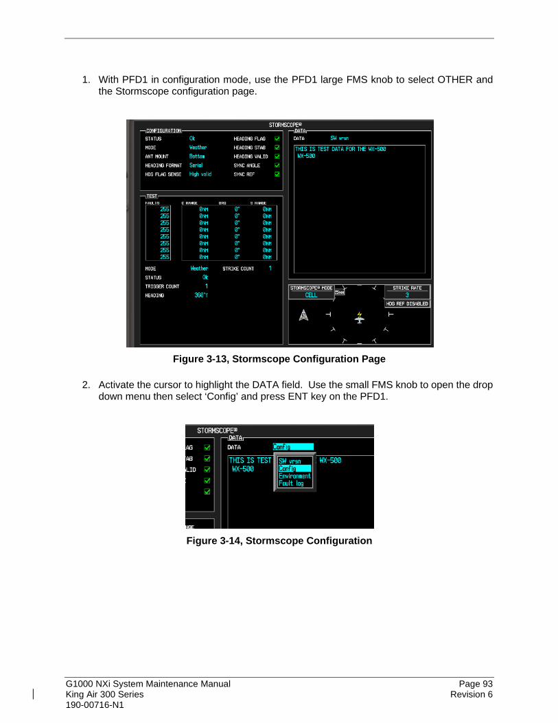
G1000 NXi System Maintenance Manual Page 93 King Air 300 Series Revision 6 190-00716-N1
1. With PFD1 in configuration mode, use the PFD1 large FMS knob to select OTHER and
the Stormscope configuration page.
Figure 3-13, Stormscope Configuration Page
2. Activate the cursor to highlight the DATA field. Use the small FMS knob to open the drop
down menu then select ‘Config’ and press ENT key on the PFD1.
Figure 3-14, Stormscope Configuration

G1000 NXi System Maintenance Manual Page 94 King Air 300 Series Revision 6 190-00716-N1
3. Verify that the DATA window shows the following:
Hdg: None: J3-1 Jumper
J3-2 Jumper
Hdg Valid Flag No Fla
Flag Sense +invld
J3-4 Open
Hdg Value <aircraft heading>
Inhibit Line Off
Antenna Mount Bottom
J3-3 Open
4. Deactivate the cursor. NOTE
The DATA window is only updated once every five seconds.
3.19 MD 302 Configuration and Sensor Calibration
NOTE
In the MD 302 Configuration Mode, any changes made to any settings will NOT be saved until you select ACCEPT CHANGES in the menu prior to exiting the Configuration Mode.
3.19.1 MD 302 Configuration 1. Open STBY INSTR circuit breaker. 2. Press and hold the MD 302 control knob on the front of the unit. 3. Close STBY INSTR circuit breaker. 4. Release the control knob when the introduction screen appears. 5. In the CONFIGURE MENU, select CONFIGURE DISPLAY by rotating the control knob
to highlight the option and press the control knob to select it. 6. In the CONFIGURE DISPLAY menu, select AIRSPEED UNITS. 7. Select KNOTS. 8. In the CONFIGURE DISPLAY menu, select EXIT. 9. In the CONFIGURE MENU, select CONFIGURE AIRCRAFT.

G1000 NXi System Maintenance Manual Page 95 King Air 300 Series Revision 6 190-00716-N1
10. Select PANEL TILT. (a) If the aircraft was not previously equipped with Collins Pro Line 21 avionics
installed at the Beechcraft factory when the aircraft was new, set the tilt value to 00.0 degrees.
(b) If the aircraft had Collins Pro Line 21 avionics installed at the Beechcraft factory when the aircraft was new, set the tilt value to 04.0 degrees.
11. In the CONFIGURE AIRCRAFT menu, select PANEL ROLL. 12. Set the value to 0.0 degrees. 13. In the CONFIGURE AIRCRAFT menu, select RANGE MMO. 14. Set the value to 0.580 MACH. 15. In the CONFIGURE AIRCRAFT menu, select RANGE MARKINGS. 16. Enter the range markings for the airframe model and engine or engine/propeller
combination required in Table 3-1 and Table 3-2: (a) Highlight the row that needs to be edited and press the control knob to select. (b) Highlight the TYPE field and press the control knob to select the field to edit. The
field background will change to green showing that it can be edited. (c) Choose the color bar TYPE needed (HALF, FULL or RAD (radial)) and press the
control knob to select. (d) Highlight the CLR field and select to enter the color needed (RED, WHI (white),
BLU (blue), or BAR (barber pole)). (e) Highlight the V1 field and select to enter the value needed. There are three digits
that need to be entered. Turn the control knob to change the first digit to the value needed and press the control knob to set. Repeat for the second and third digits.
(f) Highlight the V2 field and select to enter the value needed using the same procedure as V1. Not all V2 values will be set, the RAD and FULL TYPES automatically update V2 value based on the V1 value entered and are not changeable.
NOTES
• The V1 value is the start or lower limit of the color bar range and the V2 value is the upper limit.
• When the RAD (radial) TYPE is selected, the V1 and V2 values will be the same. The installer can only set the V1 value, the V2 value will be grayed out and unchangeable.
• When the FULL TYPE and BAR (barber pole) CLR is selected, V2 will automatically default to MAX and is unchangeable.
• For unused rows, the TYPE should be set to OFF, the CLR should be set to BLU, and V1 and V2 values should be set to “000”.
(g) Continue in sequence through all rows to enter the color bands needed and select EXIT when done.

G1000 NXi System Maintenance Manual Page 96 King Air 300 Series Revision 6 190-00716-N1
Table 3-1, MD302 Range Markings on Model 300/300LW
Range Marking
#
Range Marking
Type
Range Marking
Color
No Winglets PT6A-60 Engine
KIAS Value
No Winglets PT6A-67A Engine
(Blackhawk) KIAS Value
With Winglets PT6A-60 Engine
KIAS Value
V1 V2 V1 V2 V1 V2 1 RAD RED 92 None 103 None 95 None 2 FULL WHITE 81 100 81 100 81 100 3 HALF WHITE 100 157 100 157 100 157 4 RAD BLUE 122 None 122 None 122 None 5 FULL BAR 259 None 259 None 259 None
Table 3-2, MD302 Range Markings on Model B300/B300C
Range Marking
#
Range Marking
Type
Range Marking
Color
B300/B300C KIAS Value
B300/B300C Heavyweight KIAS Value
V1 V2 V1 V2 1 RAD RED 94 None 101 None 2 FULL WHITE 81 96 82 99 3 HALF WHITE 96 158 99 158 4 RAD BLUE 125 None 135 None 5 FULL BAR 263 None 245 None
17. In the CONFIGURE AIRCRAFT menu, select VNE TABLE. 18. Enter the table information below.
Table 3-3, MD302 VNE Setup 300/300LW B300/B300C B300, B300C
Heavyweight # ALT(FT) KTS ALT(FT) KTS ALT(FT) KTS 1 00000 259 00000 263 00000 245 2 21000 259 21000(a) 263 21000 245 3 25000 239 25000 242 25000 240 4 30000 214 30000 217 30000 216 5 35000 191 35000 194 35000 192 6 UNUSED 000 UNUSED 000 UNUSED 000 7 UNUSED 000 UNUSED 000 UNUSED 000
Table 3-3 Notes:
(a) If the aircraft is modified with STC SA03342CH, set to 24,000 ft instead of 21,000 ft.
19. Select EXIT when done entering the table. 20. Select EXIT in the CONFIGURE AIRCRAFT menu. 21. In the CONFIGURE MENU, select CONFIGURE BARO SYNC. 22. Select OFF. 23. In the CONFIGURE MENU, select CONFIGURE DIMMING.

G1000 NXi System Maintenance Manual Page 97 King Air 300 Series Revision 6 190-00716-N1
24. Select DIMMING CONTROL. 25. Select EXT 28V. 26. In the CONFIGURE DIMMING menu, select DIMMING CURVE. 27. Set the seven dimming points below by setting the point at the bottom of the scale and
counting the number of clicks up from 0. The active point that can be adjusted is colored yellow. To move to the next point to change, press the control knob.
Table 3-4, MD302 Dimming Curve Point 1 1 Point 2 5 Point 3 35 Point 4 100 (top of scale) Point 5 100 (top of scale) Point 6 100 (top of scale) Point 7 2
28. In the CONFIGURE DIMMING menu, select EXIT. 29. In the CONFIGURE MENU, select CONFIGURE DISPLAY. 30. Select ROLL DISPLAY. 31. Select FIXED POINTER. 32. In the CONFIGURE DISPLAY menu, select AIRSPEED MINIMUM. 33. Select 40 KNOTS. 34. In the CONFIGURE DISPLAY menu, select DISPLAY ORIENTATION. 35. Select VERTICAL RIGHT. 36. In the CONFIGURE DISPLAY menu, select HORIZON DISPLAY. 37. Select SHADED. 38. In the CONFIGURE DISPLAY menu, select EXIT. 39. In the CONFIGURE MENU, select CONFIGURE HEADING. 40. Select DISPLAY OFF. 41. In the CONFIGURE MENU, select ACCEPT CHANGES.
NOTE
After selecting ACCEPT CHANGES, the unit will automatically reset and enter Flight Mode.
42. Press and hold the control knob until the OPTIONS MENU appears. 43. Select INFO >. 44. Select REVIEW CFG. 45. Scroll down to the DIMMING CURVE section and confirm the lighting values entered in
Step 27. If any values are incorrect, reenter the dimming curve configuration to correct.
3.19.2 Sensor Calibration

G1000 NXi System Maintenance Manual Page 98 King Air 300 Series Revision 6 190-00716-N1
1. Connect pitot/static test equipment to the aircraft. Leave the aircraft at ground altitude and zero airspeed to allow the MD 302 to enter configuration mode. It will not enter configuration mode if it senses an airspeed input from the pitot/static test equipment.
2. Open STBY INSTR circuit breaker. 3. Press and hold the MD 302 control knob on the front of the unit. 4. Close STBY INSTR circuit breaker. 5. Release the control knob when the introduction screen appears. 6. In the CONFIGURE MENU select CALIBRATE PRESSUES. 7. Using the pitot/static test set, apply an altitude of 5000 ft. and airspeed of 120 knots.
Allow the altitude and airspeed to stabilize at these values before continuing. 8. Select CALIBRATE ALTITUDE. 9. Select YES when CALIBRATING ALTITUDE prompt is displayed. 10. When calibration is complete return to CALIBRATE PRESSURES. 11. Select CALIBRATE AIRSPEED. 12. Select YES when CALIBRATING AIRSPEED prompt is displayed. 13. When calibration is complete return to CONFIGURE MENU. 14. Select ACCEPT CHANGES. 15. MD 302 setup is complete.

G1000 NXi System Maintenance Manual Page 99 King Air 300 Series Revision 6 190-00716-N1
3.20 Flight Stream 510 Firmware Update If the optional Flight Stream 510 is installed, the technician must review the reported Flight Stream firmware version and compare it to the version approved by the STC.
Reference the STC General Arrangement drawing to find the approved firmware release.
NOTE This STC approves a major release of Flight Stream 510 and allows for periodic minor software updates to account for low-level driver and Bluetooth interface updates. Example – If the STC data specifies version 2.51 as the approved version, all minor releases within the 2.5X series are approved.
At the time of installation, minor firmware updates may be available. The Technician may check for updates to the firmware by following this procedure.
CAUTION The technician must review the Flight Stream 510 version approved by this STC and ensure a newer major release is not utilized. Otherwise, incompatibility with the GDU display software may result.
The following items are required to download the Flight Stream 510 Firmware from the Garmin Dealer Resource :
• A compatible portable device (e.g. iPad) running iOS 8.1 or later . • An active Garmin Pilot account with an active Dealer Mode subscription. • Garmin Pilot App iOS version 9.1.5 or later.
The Flight Stream service bulletin is available on the Garmin Dealer Resource website and provides all required information and instructions for uploading Firmware update to the Flight Stream 510. The steps below show how to access the Dealer Resource Support page
1. Go to www.garmin.com and click on the Dealer Resource Center link in the lower portion of the home page.
2. Enter username and password.

G1000 NXi System Maintenance Manual Page 100 King Air 300 Series Revision 6 190-00716-N1
3. Select Support then select Service & Installation Bulletins. 4. In the Keyword(s) filter, enter ‘Flight stream’. 5. A screen like the one shown below will appear. The numbers shown are for example only.
(example figure)
6. Click on the Flight Stream 510, Standard (010-01322-0X) field and press Search and a screen similar to the one shown below will be displayed:
(example figure)
7. Click on the Select Action button next to the appropriate software upgrade line-item
followed by Download. This will download a copy of the applicable Service Bulletin that provides instructions for downloading the appropriate firmware to a compatible portable IOS device and then to the Flight Stream 510 installed on the aircraft.

G1000 NXi System Maintenance Manual Page 101 King Air 300 Series Revision 6 190-00716-N1
NOTE
Flight Stream 510 firmware can only be updated over Wi-Fi with an iOS device. It cannot be updated over Wi-Fi with an Android device. To activate Dealer Mode, contact Aviation Product Support at (888) 606-5482 and request access to update Flight Stream 510 firmware as a Garmin Dealer.
NOTE
Do not disconnect the Flight Stream 510 or remove power while updating firmware.
8. The Flight Stream 510 will reboot after the firmware update is complete. Allow the Flight Stream 510 to reconnect to the Garmin Pilot app.
NOTE It may be necessary to re-select the Flight Stream 510 as the Connext Device on the Aux - Connext Setup page on the MFD.
9. Ensure that the updated firmware version of the Flight Stream 510 is displayed in the Garmin Pilot app.


G1000 NXi System Maintenance Manual Page 103 King Air 300 Series Revision 6 190-00716-N1
4.2 Servicing Information G1000 LRU maintenance is ‘on condition’ only. No component-level overhaul is required for this type design change. A “cycle” for the purposes of determining inspection requirements is defined as: Engine start-up and increase to full or partial power (as required during a normal flight), one landing gear retraction and extension and a complete shutdown.
4.2.1 On Condition Servicing ‘On Condition’ replacement and/or servicing should occur when an item exhibits conditions, symptoms, and/or abnormalities defined in Section 5 of this manual. Replacement and/or servicing should be made only after the technician troubleshoots the system to the extent determined necessary by using the guidance in this manual along with common avionics maintenance practices.
IMPORTANT! It is impossible to provide guidance for every conceivable failure scenario within the scope of this manual. Every effort has been made to provide comprehensive guidance for possible failures. The information in this document should always be combined with sound aviation maintenance practices and a thorough knowledge of the system. Use sound avionics maintenance practices when working around or on G1000 equipment.
The remainder of this document is organized in the following fashion:
• Section 4.3 lists maintenance requirements related to the G1000 system.
• Section 6 gives instructions regarding the removal and replacement of physical G1000 equipment and parts.
• Section 7 gives configuration and testing instructions to be accomplished if G1000 equipment or parts are removed or replaced.
• Section 9 specifies system return-to-service procedures.
The beginning of Section 6 provides instructions to check the software part number and version of each LRU before removing a unit. Procedures in Section 7 require the same check after LRU replacement and software loading.
IMPORTANT!
All structural repairs associated with this installation are to be addressed in accordance with the Beechcraft Structural Inspection and Repair Manual listed in Table 1-1.
NOTE
After replacing or servicing electrical components near the GMU 44 magnetometers, the Magnetometer Interference Test (reference Section 5) and Magnetometer Calibration Procedure (reference Section 7) must be performed.

G1000 NXi System Maintenance Manual Page 104 King Air 300 Series Revision 6 190-00716-N1
4.2.2 Required Tools The following tools are needed to perform maintenance tasks on G1000 equipment:
• Calibrated Milliohm meter, OR o Agilent 34410A Ammeter or equivalent o Fluke 187 Voltmeter or equivalent o Variable DC Power Supply capable of providing 1 amp current
• #2 Non-Magnetic Phillips Screwdriver
• 3/32” Hex tool
• Calibrated digital level (Required for AHRS ‘Procedure A’ Calibration)
• Calibrated VHF NAV/COM/ILS ramp tester or equivalent
• Calibrated transponder ramp tester or equivalent
• Calibrated pitot/static ramp tester
• Outdoor line-of-site to GPS satellite signals or GPS indoor repeater
• Headset/microphone
• Ground Power Unit (Capable of supplying 28 Vdc)
• Calibrated Flight Control Cable Tension Meter or equivalent
• 2 Amp, 24 V, DC Power Supply
• Calibrated torque wrench capable of measuring 0 – 70 in/lbs
• Standard sockets & wrenches (3/8”, 9/16”, and 13/16”)
• Calibrated digital thermometer suitable for measuring ambient temperature
• Laptop with RS232 emulation software
• M22885/108T8234 extraction tool
• An 0.060” 6-Spline wrench

G1000 NXi System Maintenance Manual Page 105 King Air 300 Series Revision 6 190-00716-N1
4.2.3 Special Tools The following tools may be needed to perform maintenance tasks on G1000 equipment and/or installation:
• Servo Gearbox Slip Clutch Adjustment Tool – Garmin P/N T10-00110-01
• WX-PA portable analyzer kit, Part Number 78-8060-5791-1 (If Stormscope is installed)
• Gauging Equipment Tool SPF-4 (A1M-BCH-GE)*
• If the GRA 5500 radar altimeter is installed without RS-422 connections to GIA2, obtain GRA 5500 Sensor and Main Software from the Garmin Dealer Resource Center at www.garmin.com and load with the GRA Retrofit Installation Tool part number 006-A0451-00. Download the software part number and versions listed in the General Arrangement Drawing for the GRA 5500. Instructions to download the GRA software and using the GRA Retrofit Installation Tool are in Section 3.17.
* The gauging equipment tool is used for the static port inspection for RVSM compliant aircraft only. This tool is available from Beechcraft. Any alternate tool authorized in the King Air 300 Series Maintenance Manual for RVSM static port measurements may be substituted for this tool. Refer to Chapter 34-10-00 of the King Air 300 Series Maintenance Manual for more details.

G1000 NXi System Maintenance Manual Page 106 King Air 300 Series Revision 6 190-00716-N1
4.3 Maintenance Intervals Table 4-1 shows systems and items, installed by this STC, which must undergo tests or checks at specific intervals. If the interval is shown to be in flight time as well as calendar months, the first interval reached should be used as the limit. The inspection time tables used for this STC are aligned with the existing maintenance 200 hr phase inspection program used in the current King Air 300 Series Maintenance Manual. A complete inspection cycle for the King Air 300 Series is 800 hours or 24 calendar months, divided into the following four phases:
Inspection Phase 1: To be performed at 200 hours and every 800 hours thereafter. Inspection Phase 2: To be performed at 400 hours and every 800 hours thereafter. Inspection Phase 3: To be performed at 600 hours and every 800 hours thereafter. Inspection Phase 4: To be performed at 800 hours and every 800 hours thereafter.
Those inspections that are based on flight time, calendar elapsed time or cycles shall have specific intervals stated in Table 4-1.
IMPORTANT!
As allowed in the King Air 300 Series Maintenance Manual, a tolerance of ± 20 hours for all phase inspections. Special Inspection Items - Calendar limited inspections have a tolerance of ± 12 days per 12 calendar months.
The intention of Garmin is to align this maintenance program as best possible with the existing King Air 300 Series inspection program. For a complete description of the King Air inspection program, refer to the Beechcraft King Air 300 Series Maintenance Manual listed in Table 1-1.
Table 4-1, Maintenance Intervals
Item Description/Procedure Manual Section No. Interval
G1000/GFC700 Equipment
G1000/GFC700 System Visual Inspections
Complete Visual Inspection of GWX 68 or GWX 70 Equipment and Wiring located in Nose Section
4.4 (Table 4-3) Phase 4
Complete Visual Inspection of G1000/GFC700 Equipment and Wiring located in Nose Avionics Compartment
4.4 (Table 4-4) Phase 4
Complete Visual Inspection of G1000/GFC700 Equipment and Wiring located in Pilot’s Compartment
4.4 (Table 4-5) Phase 3
Complete Visual Inspection of G1000/GFC700 Equipment and Wiring located on and behind Instrument Panel
4.4 (Table 4-6) Phase 3
Complete Visual Inspection of G1000/GFC700 Equipment and Wiring located in Cabin
4.4 (Table 4-7) Phase 3
Complete Visual Inspection of G1000/GFC700 Equipment and Wiring located in Rear Fuselage and Empennage
4.4 (Table 4-8) Phase 4

G1000 NXi System Maintenance Manual Page 107 King Air 300 Series Revision 6 190-00716-N1
Item Description/Procedure Manual Section No. Interval
GFC700 Periodic Check
Verify proper operation of the GFC700 by performing the following: Pre-Flight Test AFCS Switch Checks Autopilot Clutch Overpower Check Autopilot Operation Checks
9.11.1,
9.11.2,
9.11.3,
9.11.5
Phase 2 and 4
TAWS Functional Check Periodic TAWS function check 8.3 Phase 4
GDU 1050A PFD (Qty 2) Removal & Replacement 6.1 On Condition
GDU 1550 MFD
GMA 1347D (Qty 2) or GMA 1360D (Qty 2)
Removal & Replacement 6.2 On Condition
GMA 1347D/1360D Test 7.2.3 Phase 2 and 4
Landing Gear Aural Alert Check 7.2.4 Phase 2 and 4
SiriusXM Audio Suppression Check 7.2.5 Phase 2 and 4
GIA 63W IAU (Qty 2) or GIA 64E IAU (Qty 2)
Removal & Replacement
6.3
On Condition GEA 71 EAU (Qty 2) or GEA 71B EAU (Qty 2)
6.4
GTX 335R, GTX 345R, GTX 33( ), or GTX 3000 Transponder (Qty 2)
Removal & Replacement 6.5 On Condition
Special Inspection - Perform GTX 335R, GTX 345R, GTX 33( ), or GTX 3000 test. 7.5.4 24 Calendar Months
GDC 7400 Air Data Computer (Qty 2)
Removal & Replacement 6.7 On Condition
Special Inspection – Perform Air Data Test. 7.7.3 24 Calendar Months
RVSM checks
Special inspection – Perform RVSM Checks 8.13 24 Calendar Months
Perform RVSM checks when: • a static port is removed/installed • the RVSM critical region is
repaired or painted
8.13 On Condition
GSU 75B ADAHRS (Qty 2)
Removal & Replacement 6.9 On Condition
Magnetic variation database update. 4.6 On Condition
Special Inspection – Perform Air Data Test. 7.7.3 24 Calendar Months
Remove nose compartment pitot/static line caps at T-fittings located forward of GSU 75B units and check for moisture. Refer to Garmin drawing 005-00629-44 for line cap part numbers if replacements are needed and for torque information.
N/A 24 Calendar Months

G1000 NXi System Maintenance Manual Page 108 King Air 300 Series Revision 6 190-00716-N1
Item Description/Procedure Manual Section No. Interval
GSU 75B, GRS 77, or GRS 7800 AHRS/ADAHRS (Qty 2)
Removal & Replacement 6.9
On Condition
Magnetic variation database update. 4.6
GMU 44 Magnetometer (Qty 2)
Removal & Replacement
6.10
GDL 69A or GDL 69A SXM 6.11
GWX 68, GWX 70, or GWX 75 6.16
GMC 710 6.15
GCU 477 6.14
GTS 820/850 Traffic Unit 6.31
GTS Traffic Processor 6.31
GRA 5500 6.36
GPA 65 PA/LNA Unit 6.32
GDL 59 Wi-Fi Datalink 6.34
GSR 56 Satellite Transceiver 6.35
GSD 41 Data Concentrator 6.37
G1000 Cooling Fan Fail Annunciation Check
Verify the operation of the fan power and fan speed monitoring circuits for GIA1 fan and GIA2 fan.
9.4
820 hours max
G1000 Cooling Fan Fail Annunciation Check
Verify the operation of the fan power and fan speed monitoring circuits for PFD1 fan, MFD fan and PFD2 fan and fan fail messages.
9.4
Nose Avionics Compartment Fans Operational Check
Functional test of the GIA1 and GIA2 ported fans. Verify airflow from all fan ports. 4.14
Instrument Panel Fans Operational Check
Functional test of the PFD1, MFD and PFD2 cooling fans. Verify airflow from each fan.
4.15
G1000 Redundant Connection Check*
Verify PRI and SEC power sources for PFD 1, GIA 1, GSU 1 (or GRS 1, and GDC 1). Verify secondary paths for ADAHRS (or AHRS and ADC), engine parameters and GPS data. Verify the operation of PFD and MFD Ethernet connections. Verify ARINC connection between GSU 1 (or ADC 1 and GRS 1) and MFD. Verify DISPLAY BACKUP button function.
4.10 220 hours max
Engine Data Check* Verify engine data is available and accurate with GIA 1 or GIA 2 inoperative. 4.11 820 hours max
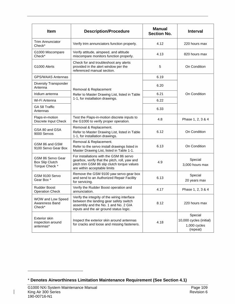
G1000 NXi System Maintenance Manual Page 109 King Air 300 Series Revision 6 190-00716-N1
Item Description/Procedure Manual Section No. Interval
Trim Annunciator Check* Verify trim annunciators function properly. 4.12 220 hours max
G1000 Miscompare Check*
Verify attitude, airspeed, and altitude miscompare monitors function properly. 4.13 820 hours max
G1000 Alerts Check for and troubleshoot any alerts provided in the alert window per the referenced manual section.
5 On Condition
GPS/WAAS Antennas
Removal & Replacement Refer to Master Drawing List, listed in Table 1-1, for installation drawings.
6.19
On Condition
Diversity Transponder Antenna 6.20
Iridium antenna 6.21
Wi-Fi Antenna 6.22
GA 58 Traffic Antennas 6.33
Flaps-in-motion Discrete Input Check
Test the Flaps-in-motion discrete inputs to the G1000 to verify proper operation. 4.8 Phase 1, 2, 3 & 4
GSA 80 and GSA 9000 Servos
Removal & Replacement. Refer to Master Drawing List, listed in Table 1-1, for installation drawings.
6.12 On Condition
GSM 86 and GSM 9100 Servo Gear Box
Removal & Replacement. Refer to the servo install drawings listed in Master Drawing List, listed in Table 1-1.
6.13 On Condition
GSM 86 Servo Gear Box Slip Clutch Torque Check *
For installations with the GSM 86 servo gearbox, verify that the pitch, roll, yaw and pitch trim GSM 86 slip clutch torque values are within acceptable limits
4.9 Special
3,000 hours max
GSM 9100 Servo Gear Box *
Remove the GSM 9100 yaw servo gear box and send to an Authorized Repair Facility for servicing.
6.13 Special
20 years max
Rudder Boost Operation Check
Verify the Rudder Boost operation and annunciation. 4.17 Phase 1, 2, 3 & 4
WOW and Low Speed Awareness Band Check*
Verify the integrity of the wiring interface between the landing gear safety switch assembly and the No. 1 and No. 2 GIA inputs and the air ground status logic.
8.12 220 hours max
Exterior skin inspection around antennas*
Inspect the exterior skin around antennas for cracks and loose and missing fasteners. 4.18
Special 10,000 cycles (initial)
1,000 cycles (repeat)
* Denotes Airworthiness Limitation Maintenance Requirement (See Section 4.1)

G1000 NXi System Maintenance Manual Page 110 King Air 300 Series Revision 6 190-00716-N1
Item Description/Procedure Manual Section No. Interval
G1000 Accessories Configuration Module Replacement (Qty 5) Removal & Replacement. 6.17
On Condition
GEA 71 or GEA 71B Backshell Thermocouple (Qty 2)
Removal & Replacement. 6.18
GTP 59 OAT Probe (Qty 2) Removal & Replacement. 6.8
PFD, MFD, and GIA Cooling Fans (Qty 5)
Removal & Replacement Refer to Master Drawing List, listed in Table 1-1, for installation drawings.
N/A
Annunciator/Switch – Emergency Frequency
Removal & Replacement. 6.25
G1000 Lightning Protection
Electrical Bonding Test
Perform the Phase 3 electrical bonding resistance check of G1000 equipment. 4.5.3 Phase 3
Perform the Phase 4 electrical bonding resistance check of G1000 equipment. 4.5.4 Phase 4
Lightning Strike to GTP 59 OAT Probe or Antenna - Actual or Suspected
Inspect the antenna/probe and surrounding installation per Table 4-9. 4.4 On Condition
Lightning Strike to the Aircraft
Inspect the GIA cooling fan discrete output to the GIA.
4.4 (Table 4-9)
On Condition
Engine/Airframe Sensors ITT Thermocouple Cable (Qty 2)
Removal & Replacement: Refer to King Air 300 Series Maintenance Manual listed in Table 1-1.
N/A On Condition
Oil Pressure Sensor (Qty 2)
Oil Temperature Sensor (Qty 2)
Torque Transmitter (Qty 2)
Fuel Flow Transmitter (Qty 2)
Prop Tachometer (Qty 2)
Engine Speed Tachometer (Qty 2)
Signal Conditioner (Qty 2)
Removal & Replacement 6.23
On Condition Annunciator/Switch – Prop Sync 6.24

G1000 NXi System Maintenance Manual Page 111 King Air 300 Series Revision 6 190-00716-N1
Item Description/Procedure Manual Section No. Interval
Other Equipment
Mechanical Standby Airspeed Indicator
Removal & Replacement 6.28.1 On Condition
Static pressure system test according to 14 CFR 91.411 and Part 43 Appendix E. N/A 24 Calendar Months
Mechanical Standby Altimeter
Removal & Replacement 6.28.2 On Condition
Test according to 14 CFR 91.411 and Part 43 Appendix E. N/A 24 Calendar Months
Mechanical Standby Attitude Indicator Removal & Replacement 6.28.3 On Condition
MD 302 Electronic Standby Instrument
Removal & Replacement 6.27.1 On Condition
Test according to 14 CFR 91.411 and Part 43 Appendix E. N/A 24 Calendar Months
MD 302 Configuration Module Removal & Replacement 6.27.2 On Condition
L-3 PS-835(C or D) Standby Battery
Removal & Replacement 6.26 On Condition
Capacity test of standby battery. 4.16.2 12 Calendar Months
Standby Battery Charge Check* Verify the standby battery is being charged. 4.16.1
220 hours max or 6 Calendar Months,
whichever comes first
Standby Instrument Electrical Power Checks*
Verify STBY ATT & STBY ALT vibrator operate and STBY ATT, STBY ALT & STBY A/S illumination function on aircraft power and standby battery power. (Note: standby compass checked during existing maintenance)
9.9 220 hours max
Annunciator/Switch - Standby Battery Removal & Replacement 6.24 On Condition
4.3.1 Discontinued Maintenance Table 4-2 shows a list of inspections and tests that are listed in the King Air 300 Series Maintenance Manual, but may be no longer required post incorporation of this STC. It is the responsibility of the installer to ensure that there are no post factory installations that would require these checks to remain.
Table 4-2, Discontinued Maintenance Intervals
Item Description/Procedure Manual Interval
AC Inverter Operational Check Phase Inspections Phases 1, 2, 3 & 4
* Denotes Airworthiness Limitation Maintenance Requirement (See Section 4.1)

G1000 NXi System Maintenance Manual Page 112 King Air 300 Series Revision 6 190-00716-N1
IMPORTANT! For installed equipment not listed in this maintenance manual, use the inspection procedures set forth in Chapter 05 of the King Air 300 Series Maintenance Manual, or other appropriate maintenance manual, as the requirements set forth by those manuals are still applicable. The requirements set forth by this document take precedence over those set forth by the King Air 300 Series Maintenance Manual, or other appropriate maintenance manual, in cases where the requirements conflict.
4.4 Visual Inspection Perform a visual inspection in accordance with requirements in Table 4-1. Check for corrosion, damage, or other defects for each of the items listed in Table 4-3 through Table 4-8. Replace any damaged parts as required. Inspection may require the temporary removal of a unit or units to gain access to connectors. Follow guidance in Section 6 for equipment removal and replacement. Refer to the King Air 300 Series Maintenance Manual listed in Table 1-1 for instructions on removing any access panels.
NOTE
It is recommended that the Phase 3 and Phase 4 electrical bonding checks contained in Section 4.5 are conducted after the Phase 3 and 4 visual inspections while access to these zones is still open.
Table 4-3, Nose Section Visual Inspection Procedure
Item Description/Procedure Initials
Gain access via the Radome for the following Inspection:
GWX 68, GWX 70, or GWX 75
a) Inspect the GWX 68, GWX 70, or GWX 75 unit, mount, and connectors for corrosion or other defects. Check the integrity of the SHIELD BLOCK ground attachments to the harness connector assembly as well as the integrity of the individual shields and their attachment.
b) Inspect wire harness for chafing, damage, proper routing of wire bundles and security of attachment in accordance with AC 43.13-1B, Chapter 11, Section 8, Paragraph 11-96 and the Nose Wire Harness Routing drawing, listed in Table 1-1.
Table 4-4, Nose Avionics Compartment Visual Inspection Procedure
Item Description/Procedure Initials
Gain access via the Nose Equipment Compartment access panel for the following Inspection:
GRS 77 or GRS 7800 (Qty 2)
(if installed)
Inspect the GRS 77 or GRS 7800 units, racks, and connectors for corrosion or other defects. Check the integrity of the SHIELD BLOCK ground attachments to the harness connector assembly as well as the integrity of the individual shields and their attachment.
GSU 75B (Qty 2)
(if installed)
a) Inspect the GSU 75B units, racks, and connectors for corrosion or other defects. Check the integrity of the SHIELD BLOCK ground attachments to the harness connector assembly as well as the integrity of the individual shields and their attachment.
b) Visually inspect the pitot/static plumbing and ensure it is secure and in good condition and routed to provide positive moisture drainage.
GIA 63W or GIA 64E (Qty 2)
Inspect the GIA 63W or GIA 64E units, racks, and connectors for corrosion or other defects. Check the integrity of the SHIELD BLOCK ground attachments to the harness connector assembly as well as the integrity of the individual shields and their attachment.

G1000 NXi System Maintenance Manual Page 113 King Air 300 Series Revision 6 190-00716-N1
Item Description/Procedure Initials
Standby Battery a) Inspect the standby battery, rack and connectors for corrosion, or other defaults.
b) Inspect the standby battery fuses and associated bracket for corrosion or other defects.
GIA Avionics Fan (Qty 2)
Inspect remote avionics fans and hoses for dirt accumulation and other damage. Remove excess dirt as required.
GTS 820/850 Traffic or GTS Traffic Processor (option)
Inspect the GTS 820/850 or GTS Traffic Processor unit (if installed), rack and connectors for corrosion or other defects. Check the integrity of the shield block ground attachments to the harness connector assembly as well as the integrity of the individual shields and their attachment.
LMD Rack and Modules Inspect the LMD rack, modules, and terminations for corrosion or other defects.
Nose Wiring harness
a) Inspect bulkhead connectors for security of attachment, corrosion or other defects.
b) Inspect wire and coax for chafing, damage, proper routing of wire bundles and security of attachment in accordance with AC 43.13-1B, Chapter 11, Section 8, Paragraph 11-96 and the Nose Wire Harness Routing drawing, listed in Table 1-1. Pay particular attention to possible areas of wire chafing such as the middle shelf feed-through hole, wheel well protrusion etc.
c) Inspect Ground blocks for security of attachment, corrosion or other defects.
d) Ensure all connectors are securely fastened.
Table 4-5, Pilot’s Compartment Visual Inspection Procedure
Item Description/Procedure Initials
Placards Inspect that all required placards are installed on the left and right control wheels. Placards must be legible, secure and in good condition. Refer to the Control Wheel Modification drawing listed in Table 1-1.
Locate equipment in the aft pedestal for the following inspection.
GCU 477 Inspect the GCU 477 unit and connector for corrosion or other defects. Check the integrity of the SHIELD BLOCK ground attachments to the harness connector assembly as well as the integrity of the individual shields and their attachment.
ADF control unit (relocated by STC)
Inspect the ADF control unit and connector for corrosion or other defects. Check the integrity of the SHIELD ground attachments to the harness connector assembly as well as the integrity of the individual shields and their attachment.
Pedestal Wiring Inspect all visible wire harness for chafing, damage, proper routing of wire bundles and security of attachment in accordance with AC 43.13-1B, Chapter 11, Section 8, Paragraph 11-96 and the Cabin Wire Harness Routing drawing, listed in Table 1-1.
GTP 59 (Qty 2)
a) Inspect the GTP 59 units and connectors for corrosion or other defects. Check the integrity of the SHIELD ground attachments to the harness connector assembly as well as the integrity of the individual shields and their attachment.
b) Inspect wire harness for chafing, damage, proper routing of wire bundles and security of attachment in accordance with AC 43.13-1B, Chapter 11, Section 8, Paragraph 11-96 and the Cabin Wire Harness Routing drawing, listed in Table 1-1.

G1000 NXi System Maintenance Manual Page 114 King Air 300 Series Revision 6 190-00716-N1
Table 4-6, Instrument Panel G1000 Equipment Visual Inspection Procedure
Item Description/Procedure Initials
Gain access to behind the instrument panel by removing the PFDs and MFD (see below). Gain access to circuit breaker panels by removing the screws which fasten the edge lit overlays to the panels
GDU 1050A PFD (Qty 2) & GDU 1550 MFD
a) Inspect the PFDs and MFD for any visual damage to the display screens or bezels including buttons and control knobs.
b) Remove the MFD and PFDs as described in Section 6. c) Inspect the mounting surface and connector for corrosion, heavy oxidation, or other
damage. Check the integrity of the SHIELD BLOCK ground attachments to the harness connector assembly as well as the integrity of the individual shields and their attachment.
d) Do not reinstall GDUs at this time. GDU cutouts provide access for visual inspections below.
G1000 Wiring harness
a) Inspect all fwd bulkhead connectors for security of attachment b) Inspect all instrument panel wiring and coax for chafing, damage, proper routing of
wire bundles and security of attachment in accordance with AC 43.13-1B, Chapter 11, Section 8, Paragraph 11-96 and the Cabin Wire Harness Routing drawing, listed in Table 1-1. Pay particular attention to possible areas of wire chafing.
c) Inspect all other exposed G1000 System wiring and coax for chafing, damage, proper routing of wire bundles and security of attachment in accordance with AC 43.13-1B, Chapter 11, Section 8, Paragraph 11-96 and the Cabin Wire Harness Routing drawing, listed in Table 1-1. Pay particular attention to possible areas of wire chafing.
GDC 7400 Air Data Computer (Qty 2) (If installed)
a) Visually inspect each GDC7400 unit, mount, and connector for corrosion or other defects. Check the integrity of the SHIELD BLOCK ground attachments to the harness connector assembly as well as the integrity of the individual shields and their attachment.
b) Visually inspect the pitot/static plumbing and ensure it is secure and in good condition and routed to provide positive moisture drainage.
GEA 71 or GEA 71B Engine/ Airframe Unit (Qty 2)
Inspect the GEA 71 or GEA 71B unit, rack, and connectors for corrosion or other defects. Check the integrity of the SHIELD BLOCK ground attachments to the harness connector assembly as well as the integrity of the individual shields and their attachment.
GMA 1347D or GMA 1360D (Qty 2)
Inspect the GMA 1347D or GMA 1360D unit (including face of unit), rack and connectors for corrosion or other defects. Check the integrity of the SHIELD BLOCK ground attachments to the harness connector assembly as well as the integrity of the individual shields and their attachment.
PFD and MFD Fans (Qty 3) Inspect fans for accumulation of dirt and other damage. Remove excess dirt as required.
GDL 69A or GDL 69A SXM
Inspect the GDL 69A unit, rack, and connectors for corrosion or other defects. Check the integrity of the SHIELD BLOCK ground attachments to the harness connector assembly as well as the integrity of the individual shields and their attachment.
GMC 710
Inspect the GMC 710 unit (including face of the unit), mount, and connectors for corrosion or other defects. Check the integrity of the SHIELD BLOCK ground attachments to the harness connector assembly as well as the integrity of the individual shields and their attachment.
Signal Conditioner (Qty 2) Inspect the signal conditioner unit, mount, and connectors for corrosion or other defects.
MD 302 Standby Indicator
a) Inspect the standby attitude indicator unit (including face of unit) and connector for corrosion or other defects. Check the integrity of the harness connector assembly in accordance with AC 43.13-1B, Chapter 11, Section 8, Paragraphs 11-96 and 11-100 and the Cabin Wire Harness Routing drawing, listed in Table 1-1.
b) Visually inspect the plumbing and harness connector assembly, and ensure it is secure and in good condition.
Mechanical Standby Attitude Indicator
Inspect the standby attitude indicator unit (including face of unit) and connector for corrosion or other defects. Check the integrity of the harness connector assembly in accordance with AC 43.13-1B, Chapter 11, Section 8, Paragraphs 11-96 and 11-100 and the Cabin Wire Harness Routing drawing, listed in Table 1-1.

G1000 NXi System Maintenance Manual Page 115 King Air 300 Series Revision 6 190-00716-N1
Item Description/Procedure Initials
Mechanical Standby Airspeed Indicator
a) Inspect the standby airspeed indicator unit (including face of unit) and connector for corrosion or other defects.
b) Visually inspect the plumbing and harness connector assembly, and ensure it is secure and in good condition.
Mechanical Standby Altimeter
a) Inspect the standby altimeter indicator unit (including face of the unit) and connector for corrosion or other defects.
b) Visually inspect the plumbing and harness connector assembly, and ensure it is secure and in good condition.
Circuit Breaker Panels
a) Inspect circuit breaker panel wiring and circuit breakers for chafing, damage, other defects and proper routing of wire bundles and security of attachment in accordance with AC 43.13-1B, Chapter 11, Section 8, Paragraph 11-96, the appropriate Circuit Breaker Panel Modification drawing, listed in Table 1-1, and the Cabin Wire Harness Routing drawing, listed in Table 1-1. Pay particular attention to possible areas of wire chafing.
b) Inspect edge lit overlay panels for damage or defect. c) Reinstall the circuit breaker edge lit overlays to the circuit breaker panels.
Placards Inspect that all required placards are installed. Placards must be legible, secure and in good condition. Refer to the Main Instrument Panel Installation drawing listed in Table 1-1.
Reinstall the MFD and PFDs as described in Section 6.
Table 4-7, Cabin Area Visual Inspection Procedure
Item Description/Procedure Initials
Antennas Inspect all external antennas for leading edge erosion and condition of base seals (GPS/WAAS, top diversity transponder(s), Iridium, top and bottom GA 58 traffic antennas, if installed)
To gain access for the following Inspections, remove floorboards in cabin at FS 185.00 and FS 246.750
Cabin Wiring Harness
Inspect all exposed wire harness for chafing, damage, proper routing of wire bundles and security of attachment in accordance with AC 43.13-1B, Chapter 11, Section 8, Paragraph 11-96 and the Cabin Wire Harness Routing drawing, listed in Table 1-1.
GFC 700 Equipment
a) Using a flashlight, inspect the roll servo, servo gearbox, connectors, support structure, and control cables to ensure that no corrosion, chafing, cracks, or other defects exist.
b) For the roll servo gearbox, check that the retaining bolt for the slip clutch cartridge is not damaged or loose.
c) Have an assistant manually move the aileron control surfaces from stop to stop and visually observe the servo and control cabling/chain. Ensure there is no binding in the control cabling or chain, and that the capstan/sprocket rotates freely.
d) Check the servo control cables in accordance with AC 43.13-1B, Chapter 7, Section 8, Paragraph 7-149 to ensure no fraying, corrosion, or other damage exists. If the condition of any cable is questionable, replace it with a new one.
e) Check the tension on the control cables. Refer to the Roll Servo Install drawing, listed in Table 1-1, for cable tension specifications:
f) Ensure that each cable is correctly attached to the clamps. g) Follow recommended checks for checking main control cables, following the
instructions in Chapter 27, Flight Controls, of the King Air 300 Series Maintenance Manual.
h) Reinstall the access panels if no other maintenance is to be performed.
To gain access for the following inspection, remove the left cabin sidewall panel at FS 158.
GPA 65 (GTS 820/850 traffic option only)
Inspect the GPA 65 PA/LNA unit (if installed), brackets and connectors for corrosion or other defects. Check the integrity of the shield block ground attachments to the harness connector assembly as well as the integrity of the individual shields and their attachment.

G1000 NXi System Maintenance Manual Page 116 King Air 300 Series Revision 6 190-00716-N1
Table 4-8, Rear Fuselage and Empennage Visual Inspection Procedure
Item Description/Procedure Initials
Wi-Fi Antenna Inspect the external Wi-Fi antenna (if installed) for leading edge erosion and condition of base seals.
To gain access for the following Inspections, refer to the servo installation drawings and the King Air 300 Series Maintenance Manual, listed in Table 1-1.
Tail Wiring Harness
a) Inspect all exposed wire harness for chafing, damage, proper routing of wire bundles and security of attachment in accordance with AC 43.13-1B, Chapter 11, Section 8, Paragraph 11-96 and the Tail Wire Harness Routing drawing, listed in Table 1-1. Pay particular attention to possible areas of wire chafing.
b) Verify security of aft bulkhead connectors.
GFC 700 Equipment
a) Using a flashlight, inspect the servos, servo gearboxes, connectors, support structure, and control cables to ensure that no corrosion, chafing, cracks, or other defects exist.
b) For pitch and pitch trim servo gearboxes, check that the retaining bolt for the slip clutch cartridge is not damaged or loose.
c) For the GSM 9100 yaw servo mount, verify the following are tightly secured: two capstan retaining screws, six drive shaft seal screws, and hole plug. If any of these items are missing or loose, remove the servo mount and send to an Authorized Service Center for repair. Also visually inspect the hydrophobic vent and remove any obstructions if present.
d) Have an assistant manually move the control surfaces and elevator trim wheel from stop to stop and visually observe the corresponding servo and control cabling. Ensure there is no binding in the control cabling, and that the capstan rotates freely.
e) Check the servo control cables in accordance with AC 43.13-1B, Chapter 7, Section 8, Paragraph 7-149 to ensure no fraying, corrosion, or other damage exists. If the condition of the cable is questionable, replace it with a new one.
f) Check the tension on the control cables. Refer to the respective servo installation drawing listed in Table 1-1 for cable tension specifications.
g) Ensure that each cable is correctly attached to the clamps. h) Follow recommended checks for checking main control cables, following the
instructions in Chapter 27, Flight Controls, of the King Air 300 Series Maintenance Manual, listed in Table 1-1.
i) Reinstall the access panels if no other maintenance is to be performed.
The GMU 44 units are mounted in the tailcone or the horizontal stabilizer. Refer to Section 6.10 for details on gaining access to the GMU.
GMU 44 (Qty 2)
For each GMU 44, do the following: a) Remove the three Phillips screws holding the GMU to the mounting bracket. Be sure
to use a non-magnetic screwdriver to avoid harming the GMU. b) Carefully remove the assembly, taking care not to damage unit or wiring, and inspect
the GMU 44 and mounting plate. c) Inspect the mounting hardware and GMU 44 for corrosion or other damage. d) Inspect all exposed GMU wiring and ensure no chafing, wear, or other damage exists
in accordance with AC 43.13-1B, Chapter 11, Section 8, Paragraph 11-96 and the Wire Harness Installation, Tail drawing, listed in Table 1-1. Pay particular attention to possible areas of wire chafing.
e) Reinstall the GMU 44.
GRA 5500 Radar Altimeter
Inspect the GRA 5500 unit (if installed) and connectors for corrosion or other defects. Check the integrity of the shield block ground attachments to the harness connector assembly as well as the integrity of the individual shield and their attachment.
GTX 335R, GTX 345R, GTX 33 ( ) or GTX 3000 (Qty 2)
Inspect the GTX units, shelf, brackets and connectors for corrosion or other defects. Check the integrity of the shield block ground attachments to the harness connector assembly as well as the integrity of the individual shields and their attachment.
GDL 59 (Wi-Fi option only)
Inspect the GDL 59 unit (if installed), shelf, brackets and connectors for corrosion or other defects. Check the integrity of the shield block ground attachments to the harness connector assembly as well as the integrity of the individual shields and their attachment.
GSR 56 (iridium option only)
Inspect the GSR 56 unit (if installed), shelf, brackets and connectors for corrosion or other defects. Check the integrity of the shield block ground attachments to the harness connector assembly as well as the integrity of the individual shields and their attachment.

G1000 NXi System Maintenance Manual Page 117 King Air 300 Series Revision 6 190-00716-N1
Item Description/Procedure Initials
GSD 41 (FDR option only)
Inspect the GSD 41 unit (if installed), shelf, brackets and connectors for corrosion or other defects. Check the integrity of the shield block ground attachments to the harness connector assembly as well as the integrity of the individual shields and their attachment.
Table 4-9, Lightning Strike Inspection Procedure
Item Description/Procedure Initials
GTP 59 OAT Probe or Antenna
A post lightning strike inspection must be done for a suspected or actual lightning strike to antennas or the OAT probes. Inspect antenna/probe and surrounding installation to ensure that there is no structural damage around the areas where lightning may have attached. If there is visible sign of damage to the probe or antenna, then it should be replaced per Section 6. Refer to the Beechcraft Structural Inspection and Repair Manual listed in Table 1-1 for any aircraft structural repairs.
GMU 44 (Qty 2)
A “Magnetometer Interference Test” per Section 5.17.4 and “GSU 75B, GRS 77, or GRS 7800 and GMU 44 Magnetic Calibration” per Section 7.10.3 must be performed after a suspected or actual lightning strike. A lightning strike can result in a change in the magnetic properties of steel components in the area of the magnetometers which can cause unacceptable magnetic interference levels.
GIA Fans Verify the GIA cooling fan discrete out is correctly activating when the fan is not working by performing tests per Section 9.4.
4.5 Electrical Bonding Test The following bonding tests are provided for G1000-equipped King Air 300 Series aircraft as a requirement beyond what is given in the aircraft maintenance manual. The electrical bonding checks are split into two tests, Phase 3 Electrical Bonding Test and Phase 4 Electrical bonding test. This places the bonding test requirement for each G1000 LRU in the same phase as the visual inspection of that zone to minimize access requirements.
4.5.1 Requirements All G1000 equipment must be installed. Gain access for the procedure listed below in Section 4.5.3 and 4.5.4 as required and in accordance with the aircraft maintenance manual. It is recommended that these tests are conducted after visual inspection of the zone to minimize access requirements.
4.5.2 Test Equipment A milliohm meter and Kelvin probes are recommended for this test. However, an alternate method may be used to provide equivalent results by using the following procedure and a standard voltmeter, power supply with adjustable current limit, and ammeter. The test set up for this alternate method is described below. All test equipment used for the bond checks must be calibrated.
1. Connect the positive lead of the power supply to airframe ground. Connect/touch the positive lead of the voltmeter to the same point.
NOTE
Ensure that the voltmeter and power supply probes do not touch, so as not to induce contact resistance.

G1000 NXi System Maintenance Manual Page 118 King Air 300 Series Revision 6 190-00716-N1
2. Touch negative lead of power supply to each of the test points listed while performing Step 3. At each required point, configure the power supply to produce 1 amp before measuring voltage. (Use an ammeter to ensure current is within minimum of 1 amp ±100 milliamp at each point). Do not allow the reference current to exceed 1.5 amps for safety.
3. With the current set to 1A, the voltage reading will be the value of the bonding resistance. Set the voltmeter to measure millivolts and null the reading. Measure the voltage from airframe ground (step 1) to each required test points and record the voltage. (Perform Step 2 at each required point and ensure that minimum of 1 amp ±100 milliamp is present when measuring the voltage.) TIP: When a 1A current is used all the millivolt readings are the same as mΩ, and
required no further calculation of bond resistance. If 1 amp reference current cannot be maintained and is higher divide the measured voltage by current to get the resistance value.
4.5.3 Phase 3 Electrical Bonding Procedure Using one of the two measurement methods in Section 4.5.2 record the bonding measurement for the following equipment. Some equipment in the list is optional and may not be installed. Ensure that the PFD1 unit, PFD2 unit, MFD unit, and GMC 710 test points, no more than 30 mΩ is present. Ensure that at other unit test points, no more than 5 mΩ is present.
Pilot Compartment
• Top metal case of PFD 1: __________ mΩ • PFD1 Cooling fan metal base: __________ mΩ • Top metal case of PFD 2: __________ mΩ • PFD2 Cooling fan metal base: __________ mΩ • Top metal case of MFD: __________ mΩ • MFD Cooling fan metal base: __________ mΩ • Top metal case of GMA 1347D or GMA 1360D #1: __________ mΩ • Top metal case of GMA 1347D or GMA 1360D #2: __________ mΩ • Top metal case of GMC 710: __________ mΩ • GEA 71 or GEA 71B #1 body: __________ mΩ • GEA 71 or GEA 71B #2 body: __________ mΩ • GDC 7400 #1 body (if installed): __________ mΩ • GDC 7400 #2 body (if installed): __________ mΩ • OAT 1 Probe base nut (inside fuselage): __________ mΩ • OAT 2 Probe base nut (inside fuselage): __________ mΩ • GDL 69A body: __________ mΩ • Engine Signal Conditioner #1 near mounting holes of case: __________ mΩ • Engine Signal Conditioner #2 near mounting holes of case: __________ mΩ • Top metal case of GCU 477: __________ mΩ

G1000 NXi System Maintenance Manual Page 119 King Air 300 Series Revision 6 190-00716-N1
Cabin Compartment
• GSA 80 (Roll) Servo body: __________ mΩ • GPA 65 body (if installed): __________ mΩ
4.5.4 Phase 4 Electrical Bonding Procedure Using one of the two measurement methods in Section 4.5.2 record the bonding measurement for the following equipment. Some equipment in the list is optional and may not be installed. Ensure that at each other test point, no more than 5 mΩ is present.
Nose Section
• GWX 68, GWX 70, or GWX 75 body: __________ mΩ
Nose Avionics Compartment
• GIA 1 top: __________ mΩ • GIA 2 top: __________ mΩ • GSU 75B, GRS 77, or GRS 7800 #1 metal base: __________ mΩ • GSU 75B, GRS 77, or GRS 7800 #2 metal base: __________ mΩ • Standby battery: __________ mΩ • GTS 820/850/Processor metal base: __________ mΩ
Rear Fuselage and Empennage
• GMU 44 #1 metal base: __________ mΩ • GMU 44 #2 metal base: __________ mΩ • GSA 80 (Pitch) Servo body: __________ mΩ • GSA 80 (Pitch Trim) Servo body: __________ mΩ • GSA 9000 (Yaw) Servo body: __________ mΩ • GRA 5500 Radar Altimeter __________ mΩ • GTX 335R #1, GTX 345R #1, GTX 33 #1, or GTX 3000 #1 top: __________ mΩ • GTX 335R #2, GTX 33 #2, or GTX 3000 #2 top: __________ mΩ • GDL 59 top: __________ mΩ • GSR 56 metal base: __________ mΩ • GSD 41 top: __________ mΩ

G1000 NXi System Maintenance Manual Page 120 King Air 300 Series Revision 6 190-00716-N1
Antennas Test points are between the inside connector body and nearby exposed structure with coaxes disconnected.
• GA 36 (GPS #1): __________ mΩ • GA 37 (GPS #2): __________ mΩ • GA 58 (GTS Traffic): __________ mΩ
4.6 GSU 75B, GRS 77, or GRS 7800 Earth Magnetic Field Updates The GSU 75B, GRS 77, or GRS 7800 utilizes an Earth magnetic field model which is updated once every five years. The update is expected to be available from Garmin every five years, as long as the GSU 75B, GRS 77, or GRS 7800 remain Garmin-supported products. The G1000 system alerts the operator that the magnetic field database is out of date by issuing the message “AHRS SERVICE – AHRS Magnetic-field model needs update”. Garmin will distribute updates as part of the navigation database cycle. If the IGRF model in the update is newer than the model installed, a prompt will appear for each GRS/GSU (Select “OK” to update the IGRF Magnetic Field Model). Use the FM Knob and ENT key to select “OK”.
4.7 GSA 80 Greasing Procedure The GSA 80 servo greasing procedure is required only when the GSA 80 is removed and reinstalled. Refer to Section 6.12 for details.

G1000 NXi System Maintenance Manual Page 121 King Air 300 Series Revision 6 190-00716-N1
4.8 Flaps-in-motion Discrete Input Check To perform this check, all G1000 and GFC 700 equipment must be installed and operational. Start PFD1 in Configuration Mode and go to the GIA Page Group and select the GIA I/O Configuration Page using the FMS knob. Perform the following checks:
Figure 4-1, GIA I/O Page
False Invalid True Valid
Figure 4-2, Discrete Indications
1. Verify the DATA indicators of the discrete inputs labeled ‘FLAP EXTEND’ and ‘FLAP RETRACT’ show an invalid condition.
2. Extend the flaps down. While the flaps are traveling down, check that the DATA indicator of the discrete input labeled ‘FLAP EXTEND’ changes to a valid condition.
3. When the flap motion is completed, verify the DATA indicators of the discrete inputs labeled ‘FLAP EXTEND’ and ‘FLAP RETRACT’ show an invalid condition.
4. Retract the flaps up. While the flaps are traveling up, check that the DATA indicator of the discrete input labeled ‘FLAP RETRACT’ changes to a valid condition.
5. When the flap motion is completed, verify the DATA indicators of the discrete inputs labeled ‘FLAP EXTEND’ and ‘FLAP RETRACT’ show an invalid condition.
6. Repeat steps 1 through 5 for GIA2. 7. The flap discrete input check is complete.

G1000 NXi System Maintenance Manual Page 122 King Air 300 Series Revision 6 190-00716-N1
4.9 GSM 86 Slip Clutch Torque Check Procedure Perform the test per Sections 4.9.1 (preferred) or 4.9.2. To perform the procedure, all G1000 system equipment must be installed and operational.
4.9.1 Automated Slip Clutch Test Procedure 1. Before starting test, select the AVIONICS MASTER PWR, EXT PWR, and BATT
switches to OFF. 2. Press and hold the ENT key on PFD1 while selecting the AVIONICS MASTER PWR,
EXT PWR, and BATT switches to ON. 3. Release the ENT key after ‘INITIALIZING SYSTEM’ appears in the upper left corner of
PFD1. (Steps 1 through 3 put PFD1 in Configuration Mode and PFD2 / MFD in normal mode.) 4. With the MFD in Normal Mode, press the red DISPLAY BACKUP button on the pilot’s
GMA audio panel to place the MFD in reversion mode. 5. With PFD1 in Configuration Mode, go to the GFC Page Group and select the GFC
STATUS page using the FMS knobs.
Figure 4-3, GFC Status Page
IMPORTANT!
It is highly recommended that the following test be performed at temperatures between 50° F and 120° F.
6. Use GIA 1 in the SELECT GIA UNIT field for these tests. Use the FMS knob to select the desired servo (Pitch, Roll, Yaw or Pitch Trim).
7. Verify that the Monitor Board and Control Board PFT status fields show PASSED.

G1000 NXi System Maintenance Manual Page 123 King Air 300 Series Revision 6 190-00716-N1
8. Verify that the aircraft control surface to be checked is free to travel throughout its range of motion.
9. Press the Test SVO softkey on the PFD. Follow prompts to begin the test. IMPORTANT!
If the test must be stopped, firmly grasp the aircraft control being moved and press the red AP DISC switch on the aircraft control wheel. If an abnormal disconnect of a servo occurs, reset the AFCS SERVO circuit breaker and repeat the test.
10. When test is completed, verify the CLUTCH TEST PASS message is displayed on the MFD.
11. Repeat steps 6 through 10 for each servo axis (Pitch, Roll, and Pitch Trim). Yaw is not tested.
12. If the CLUTCH TEST FAIL message is displayed on the MFD for any axis, repeat the test twice in the failed axis. If the tests do not pass, the GSM 86 slip clutch cartridge must be removed from the aircraft and either be retested using the Manual Slip Clutch Test Procedure or replaced.

G1000 NXi System Maintenance Manual Page 124 King Air 300 Series Revision 6 190-00716-N1
4.9.2 Manual Slip Clutch Test Procedure This test is an alternative to the automated and manual slip clutch test procedures. The GSM 86 servo gearbox does not have an adjustable slip clutch; however, the torque value can be measured using this procedure.
IMPORTANT!
This adjustment requires the use of the Garmin servo adjustment fixture, P/N T10-00110-01. For detailed operating instructions for the fixture, refer to GSA8X / GSM85(A) Installation Manual, listed in Table 1-2. It is highly recommended that the following test be performed at temperatures between 50° F and 120° F.
1. Remove the GSM 86 servo gearbox as per Section 6.13. 2. Place the GSM 86 servo gearbox on the slip-clutch adjustment fixture and secure with
the toggle clamps. Install the fixture cable between the capstan under test and the fixture capstan. Remove the slack in the cable using the tension adjustment knob. Tighten the two wingnuts on bottom of fixture while holding the top thumbscrews.
3. Attach a socket to a calibrated torque wrench of appropriate range and place on top of the fixture capstan. Adjust the wrench support fixture so that it contacts the handle in the appropriate location.
4. Connect a 2 Amp, 24 V, DC power supply to the fixture. 5. Place the solenoid switch to "on" and move the direction switch to the clockwise or
counter-clockwise position. Allow the clutch to rotate at least one revolution in each direction (note: the capstan itself is fixed.)
6. Observe the torque reading for at least two full revolutions in each direction. Ensure the minimum and maximum torque readings are within the tolerance specified.
7. If the minimum and maximum torque values are within the specified range in Table 4-10, the GSM slip clutch is acceptable. Reinstall the GSM 86 servo gearbox per Section 6.13.
8. If the minimum and maximum torque values are not within the specified range in Table 4-10, the GSM 86 slip clutch cartridge must be replaced.
Table 4-10, GSM 86 Slip Clutch Torque Settings
Servo Pitch Trim Pitch Roll
GSM 86 66 -9/+10 in-lbs 32 ± 4 in-lbs 135 ±20 in-lbs

G1000 NXi System Maintenance Manual Page 125 King Air 300 Series Revision 6 190-00716-N1
4.10 G1000 Redundant Connection Check Perform the following steps to verify the following:
(A) The primary (PRI) and secondary (SEC) power sources for GIA 1, GRS 1, PFD 1, and GDC 1.
(B) The AHRS and ADC data path to PFD. (C) PFD and MFD Ethernet connection (includes ARINC connection between ADC and MFD
and DISPLAY BACKUP button function). (D) Engine data availability to the displays and GPS data availability to the AHRS with either
GIA inoperative. (A) PRI and SEC power sources for PFD 1, GIA 1, GSU 1, GRS 1 and GDC 1 check
1. Connect a ground power unit to the external power receptacle and turn on the ground power unit.
2. Set the BAT, EXT PWR, and AVIONICS MASTER PWR switches to ON. 3. With the G1000 system in normal mode, pull the following circuit breakers on the right
hand circuit breaker panel:
• PFD 1 (PRI)
• AHRS 1 (PRI) or ADAHRS 1 (PRI)
• ADC 1 (PRI) if installed.
• GIA 1 (PRI) 4. Wait at least 5 seconds, then verify the data on PFD1 remains valid and the following
alert messages are not present:
• GIA 1 FAIL (or any related message such as COM1, NAV1, XPDR1, GPS1)
• AHRS 1 FAIL
• ADC 1 FAIL
• FAILED DATA PATH 5. Close the circuit breakers listed in step 3. 6. Repeat step 4. 7. Pull the following circuit breakers on the right hand circuit breaker panel:
• PFD 1 (SEC)
• AHRS 1 (SEC) or ADAHRS 1 (SEC)
• ADC 1 (SEC) if installed
• GIA 1 (SEC) 8. Wait at least 5 seconds, then repeat step 4. 9. Close the circuit breakers listed in step 7.

G1000 NXi System Maintenance Manual Page 126 King Air 300 Series Revision 6 190-00716-N1
(B) AHRS and ADC data path check 1. Verify there are no AHRS loss of data messages, such as:
• AHRS not receiving any GPS information
• AHRS not receiving backup GPS information
• AHRS using backup GPS source 2. Place the G1000 in configuration mode. 3. In the GIA page group, go to the GIA RS-232/ARINC 429 CONFIG page. 4. With GIA1 selected in the SELECT UNIT window, verify the following indicators are
green:
• RS232 Channel 1 [(GDC72 #1) or (GDC74 #1)]
• RS232 Channel 6 [(GRS79 #1), (GRS77 #1), or (GRS7800 #1)]
• ARINC 429 IN2 [(GSU75 #2), (GRS77 #2) or (GRS7800 #2)]
• ARINC 429 IN5 [(GDC74 #1)] (only if a GDC 7400 installed)
• ARINC 429 IN6 [(GSU75 #1), (GRS77 #1), or (GRS7800 #1)] (Ref. Section 5.1.1.2.) 5. With GIA2 selected in the SELECT UNIT window, verify the following indicators are
green:
• RS232 Channel 1 [(GDC72 #2) or (GDC74 #2)]
• RS232 Channel 6 [(GRS79 #2), (GRS77 #2), or (GRS7800 #2)]
• ARINC 429 IN2 [(GSU75 #1), (GRS77 #1), or (GRS7800 #1)]
• ARINC 429 IN5 [(GDC74 #2)] (only if a GDC 7400 is installed)
• ARINC 429 IN6 [(GSU75 #2), (GRS77 #2), or (GRS7800 #2)] (Ref. Section 5.1.1.2.) 6. In the GDU page group, go to the GIA RS-232/ARINC 429 CONFIG page. 7. With PFD1 selected in the SELECT UNIT window, verify the following indicators are
green:
• ARINC 429 IN1 [(GSU75 #1), (GRS77 #1), or (GRS7800 #1)]
• ARINC 429 IN2 [(GDC72 #1) or (GDC74 #1)] (Ref. Section 5.1.1.1.) 8. With PFD2 selected in the SELECT UNIT window, verify the following indicators are
green:
• ARINC 429 IN1 [(GSU75 #2), (GRS77 #2), or (GRS7800 #2)]
• ARINC 429 IN2 [(GDC72 #2) or (GDC74 #2)] (Ref. Section 5.1.1.1.) 9. Restart the G1000 in normal mode.

G1000 NXi System Maintenance Manual Page 127 King Air 300 Series Revision 6 190-00716-N1
(C) PFD and MFD Ethernet connection check (includes ARINC connection check between ADC1 and MFD and between GRS1 and MFD, and the DISPLAY BACKUP button check)
1. On the right hand circuit breaker panel, open the MFD circuit breaker: 2. Verify NAV 1, COM 1, NAV 2, and COM 2 remain valid on both PFD 1 and PFD 2. 3. Close the MFD circuit breaker and wait for MFD to initialize. 4. Open the PFD 2 circuit breaker. 5. Press the DISPLAY BACK UP button on GMA 1. 6. Verify NAV 2 and COM 2 are each replaced by a red X and NAV 1 and COM 1 remain
valid on both the MFD and PFD 1. 7. Press the DISPLAY BACK UP button on GMA 1 to return to normal mode. 8. Close the PFD 2 circuit breaker and wait for PFD 2 to initialize. 9. Open the PFD 1 (PRI) and PFD 1 (SEC) circuit breakers. 10. Press the DISPLAY BACK UP button on GMA 2. 11. Verify NAV 1 and COM 1 are each replaced by a red X and NAV 2 and COM 2 remain
valid on both the MFD and PFD 2. 12. Verify ADC 1 data and GRS 1 data can be displayed on the MFD. 13. Press the DISPLAY BACK UP button on GMA 2 to return to normal mode. 14. Close the PFD 1 (PRI) and PFD 1 (SEC) circuit breakers and wait for PFD 1 to initialize.
(D) Engine data availability to the displays and GPS data availability to the AHRS with either GIA inoperative check 1. Open GIA1 primary and secondary CBs. 2. Verify the following:
• NAV 1 and COM 1 tuning fields on PFD 1 and PFD 2 are invalid (red X).
• L/R engine data remains valid.
• XPDR1 is Inoperative.
• GMA1 is Inoperative.
• AHRS1 is using backup GPS source.
• AHRS2 not receiving backup GPS Information.
• An amber BOTH ON GPS2 is displayed on PFD 1 and PFD 2.
• AHRS and ADC data remain valid on PFD 1 and PFD 2. 3. Close GIA1 primary and secondary CBs. Allow system to re-acquire satellites and
return to normal display modes. 4. Open GIA2 CB. 5. Verify the following:
• NAV 2 and COM 2 tuning fields on PFD 1 and PFD 2 are invalid (red X).
• L/R engine data remains valid.
• XPDR 2 is Inoperative.

G1000 NXi System Maintenance Manual Page 128 King Air 300 Series Revision 6 190-00716-N1
• GMA 2 Is Inoperative.
• AHRS 2 is using backup GPS source.
• AHRS 1 not receiving backup GPS Information.
• An amber BOTH ON GPS1 is displayed on PFD 1 and PFD 2.
• AHRS and ADC data remain valid on PFD 1 and PFD 2. 6. Close GIA2 CB. Allow system to re-acquire satellites and return to normal display
modes. 7. Open GIA1 primary and secondary CBs and GIA2 CB. 8. Verify the following:
• NAV 1, COM 1, NAV 2, and COM 2 flag invalid on both PFD 1 and PFD 2.
• GPS CDI flags DR on PFD.
• NAV 1 & NAV 2 CDI loses deviation bar.
• XPDR field flags invalid on PFD.
• Engine Instrument field flags invalid on MFD.
• All AHRS & ADC fields remain valid.
• Red AFCS status annunciation given.
• If equipped with TAWS, TAWS FAIL annunciation given.
• If equipped with ADF and/or DME, ADF/DME windows flag invalid. 9. Restore power to both GIA units. The G1000 Redundant Connections Check is
complete.

G1000 NXi System Maintenance Manual Page 129 King Air 300 Series Revision 6 190-00716-N1
4.11 Engine Data Check Accomplish this section to verify the engine data availability and validity for ITT and torque. Remove the left and right engine cowling (Ref. King Air 300 Series Maintenance Manual, Chapter 71-10-00) to gain access to the engine harness connectors and reinstall cowling when testing is complete.
4.11.1 ITT Required test equipment:
Table 4-11, Engine Data Check Test Equipment Test Equipment Make/Requirement
Calibrated DC Power Supply Or ITT Tester
0-100 mVDC Or 200C-1200C
(Fluke 525B, Fluke 725, or equivalent)
1. Ensure left engine firewall connector J104 and right engine firewall connector J105 are disconnected.
2. Connect the DC Power Source or ITT Tester across the following left engine firewall connector pins.
Aircraft Model Aircraft Serial No. Firewall Connector/Pins
300 ALL J104 - W (HI) (Chromel-White) J104 - T (LO) (ALML-Green)
B300 FL-1 THRU FL-119, FL 121, FM-1 THRU FM-8,
FN-1
J104 - W (HI) (Chromel-White) J104 - T (LO) (ALML-Green)
B300 FL-120, FL-122 and
LATER, FM-9 and LATER J104 - R (HI) (Chromel-White) J104 - N (LO) (ALML-Green)
3. Apply external power to aircraft and start the G1000 in normal mode. 4. Verify the gauge indications at the test points in Table 4-12. are within specified
tolerances.
NOTE If the ITT Tester is not temperature compensated or if using the DC Signal method, use the chart shown in Figure 4-4 to convert the ambient temperature to millivolts and subtract from the DC Signal value in Table 4-12.
Table 4-12, ITT Indication Test Points
Test Point (degC)
DC signal (mV, subtract temp offset)
Indication (degC)
200 8.137 200 +/- 17
400 16.395 400 +/- 17
600 24.902 600 +/- 12
800 33.277 800 +/- 7
1000 41.269 1000 +/- 12
1200 48.828 1200 +/- 17

G1000 NXi System Maintenance Manual Page 130 King Air 300 Series Revision 6 190-00716-N1
5. On the right hand circuit breaker panel, open the GIA1 (PRI) and GIA1 (SEC) circuit
breakers, and verify the last observed ITT indication remains unchanged. Reset the GIA1 (PRI) and GIA1 (SEC) circuit breakers.
6. Repeat test for the right engine gauge using right engine firewall connector J105. Connect the DC Power Source or ITT Tester across the following right engine firewall connector pins.
Aircraft Model Aircraft Serial No. Firewall Connector/Pins
300 ALL J105 - W (HI) (Chromel-White) J105 - T (LO) (ALML-Green)
B300 FL-1 THRU FL-119, FL 121, FM-1 THRU FM-8,
FN-1
J105 - W (HI) (Chromel-White) J105 - T (LO) (ALML-Green)
B300 FL-120, FL-122 and LATER, FM-9 and
LATER
J105 - R (HI) (Chromel-White) J105 - N (LO) (ALML-Green)
7. Pull the GIA 2 circuit breaker, and verify the last observed ITT indication remains
unchanged. Reset the GIA 2 circuit breaker. 8. If any ITT readings are not within the Indication tolerance in Table 4-12, troubleshoot the
aircraft ITT system per Textron Aviation King Air 300 Series Maintenance Manual, Chapter 77, using the following checks -
a. Airframe ITT Wire Harness Continuity Check. Note for this test, the GEA 71B unit replaces the previously installed analog ITT indicator. Remove the GEA 71B unit from its rack to conduct the continuity test from the thermocouple terminal block to the GEA 71B unit ITT input pins. For this check connect left and right engine firewall connectors J104 and J105, respectively.
b. ITT Thermocouple Loop Resistance Check
c. ITT Thermocouple Insulation Resistance Check
9. Turn off the G1000 system and remove external power from aircraft. 10. Reinstall and safety the left J104 and right J105 engine firewall connectors.

G1000 NXi System Maintenance Manual Page 131 King Air 300 Series Revision 6 190-00716-N1
Figure 4-4, Ambient Temperature Conversion Chart
4.11.2 Torque Required test equipment:
Table 4-13, Engine Data Check Test Equipment Test Equipment Make/Requirement
Calibrated DC Power Supply 0-10 VDC (Fluke 525B, Fluke 725, or equivalent)
1. Disconnect the left engine firewall connector J102 and right engine firewall connector J103.
2. Inject a DC voltage into GEA 1 by connecting the DC power supply to the left engine firewall connector-pins J102-C (HI) and J102-R (LO).
3. Apply external power to aircraft and start the G1000 system in normal mode. 4. Verify the gauge indications at the test points in Table 4-14 are within the specified
tolerances. Table 4-14, Torque Indication Test Points
Test Point (VDC) Torque Indication (%)
0.000 0 +/- 1.1
1.028 45 +/- 0.9
1.713 75 +/- 0.9
2.285 100 +/- 0.3

G1000 NXi System Maintenance Manual Page 132 King Air 300 Series Revision 6 190-00716-N1
5. On the right hand circuit breaker panel, open the GIA1 (PRI) and GIA1 (SEC) circuit breakers, and verify the last observed torque indication remains unchanged. Reset the GIA1 (PRI) and GIA1 (SEC) circuit breakers.
6. Repeat Table 4-14 test for the right engine by injecting a DC voltage into GEA 2 by connecting the DC power supply to the right engine firewall connector-pins J103-C (HI) and J103-R (LO).
7. Pull the GIA 2 circuit breaker, and verify the last observed torque indication remains unchanged. Reset the GIA 2 circuit breaker.
8. Turn off the G1000 system and remove external power from aircraft. 9. Reinstall and safety the left J102 and right J103 engine firewall connectors.
4.12 Trim Annunciator Check This procedure checks the pitch trim (PTRM) annunciation from both GIA 1 and GIA 2 and the mis-trim AFCS status alerts.
1. Ensure the G1000 is in normal mode, autopilot is not engaged, and the AFCS mode controller XFR key is selected to the pilot side.
2. Press the left part of the pilot’s pitch-trim switch upwards for approximately 10 seconds and verify that the red PTRM annunciation is displayed on both PFD 1 and PFD 2.
3. Release the switch and wait for the PTRM annunciation to clear. 4. Press the left part of the pilot’s pitch-trim switch downwards for approximately 10
seconds and verify that the red PTRM annunciation is displayed on both PFD 1 and PFD 2.
5. Release the switch and wait for the PTRM annunciation to clear. 6. Repeat Steps 2 through 5 for the right part of the pilot’s pitch-trim switch. 7. Repeat Steps 2 through 6 for the copilot’s pitch-trim switch. 8. Using the AFCS mode controller, select copilot side by pressing the XFR key on the
mode controller (changes active GIA to GIA 2). 9. Repeat Steps 2 through 7 and verify annunciations are displayed on both PFD 1 and
PFD 2. 10. Using the AFCS mode controller, re-select pilot side by pressing XFR key on the mode
controller (changes active GIA back to GIA 1). 11. Hold the control yoke with elevators and ailerons in the neutral positions (control wheel
level and at the mid-point position between full forward and full aft). Position the pitch trim wheel to 0° degrees.
12. Press the Go Around button on the throttle and engage the autopilot. Apply a forward load on the control yoke. Verify that the pitch trim wheel rotates in the UP direction.
13. Disengage the autopilot and flight director. Use the pitch-trim switch (or the pitch-trim wheel) to trim full down.
14. Hold the control yoke in the full forward position. 15. Engage the autopilot, apply firm aft pressure on the control yoke for approximately 10
seconds, allowing the pitch-trim wheel to move freely. Verify that the amber ELE↓ annunciator is displayed on both PFD 1 and PFD 2.

G1000 NXi System Maintenance Manual Page 133 King Air 300 Series Revision 6 190-00716-N1
16. Disengage the autopilot and use the pitch-trim switch (or the pitch-trim wheel) to trim full up.
17. Move the control yoke to the full aft position and hold. 18. Press the Go Around button on the throttle and engage the autopilot. Apply firm forward
pressure on the control yoke for approximately 10 seconds, allowing the pitch-trim wheel to move freely. Verify that the amber ELE↑ annunciator is displayed on both PFD 1 and PFD 2.
19. Disengage the autopilot. NOTE
If the ELE annunciation appears during any of the following steps, reset the trim wheel and repeat the test step.
20. Use the pitch-trim switch (or the pitch-trim wheel) to trim full down. 21. Hold the elevator in the neutral position (control wheel at the mid-point position between
full forward and full aft), press the HDG and ALT buttons on the mode controller and center the heading bug.
22. Engage the autopilot and turn the heading knob to set the heading bug to the right of center. Hold the control yoke centered for approximately 10 seconds. Verify that the amber AIL→ annunciator is displayed on both PFD 1 and PFD 2.
23. Turn the heading knob to set the heading bug to the left of center. Hold the control yoke centered for approximately 10 seconds. Verify that the amber ←AIL annunciator is displayed on both PFD 1 and PFD 2.
24. Disengage the autopilot and clear all flight director modes. 25. Ensure the aircraft is on the ground and the nose wheel is approximately straight.
NOTE
In the following steps, slow, continuous rudder pedal movement is needed to overcome clutch torque. If pedal movement is stopped before the annunciation is displayed, return the rudder pedals to the neutral position and repeat step.
26. Engage the yaw damper. 27. Begin to apply pressure slowly to the right rudder pedal. When pedal resistance is felt,
continue to apply pressure slowly for approximately 20 to 30 seconds. 28. Verify that the amber ←RUD annunciator is displayed on both PFD 1 and PFD 2. 29. Reposition the rudder pedals to the neutral position. 30. Begin to apply pressure slowly to the left rudder pedal. When pedal resistance is felt,
continue to apply pressure slowly for approximately 20 to 30 seconds. 31. Verify that the amber RUD→ annunciator is displayed on both PFD 1 and PFD 2. 32. Reposition the rudder pedals to the neutral position. 33. Disengage yaw damper. 34. The Trim Annunciator Check is complete.

G1000 NXi System Maintenance Manual Page 134 King Air 300 Series Revision 6 190-00716-N1
4.13 G1000 Miscompare Checks This procedure will check the AHRS, airspeed and altitude miscompare monitors. Accomplish the following checks with the aircraft positioned where it can receive GPS signals and magnetic heading. Access to AHRS 1/ADAHRS 1 and AHRS 2/ADAHRS 2 is required during this test.
1. Unfasten the AHRS 1/ADAHRS 1 and 2 units and set loose in their racks. Do not disconnect connectors or pitot/static lines.
2. Connect a pitot/static test set to the aircraft left side pitot and static ports (pilot’s side). Do not connect a pitot/static test set to the right side pitot/static ports (copilot’s side) at this time.
3. Ensure the G1000 is operating in normal mode. 4. Set the baro-correction on PFD 1 and PFD 2 to STD. 5. On the AFCS mode controller, press the ALT, HDG, and AP buttons and verify autopilot
engages. 6. Slowly increase the altitude to simulate an altitude miscompare of greater than 200 ft.
Verify PFD 2 altitude does not increase, autopilot does not disconnect, and an amber ALT box is displayed in the altitude tape of PFD 1 and PFD 2.
7. Reduce left side altitude to ambient pressure. Verify the amber ALT box is removed from both PFD(s).
8. Repeat Steps 6 and 7 except reducing the altitude to simulate a miscompare greater than 200ft.
9. Connect a pitot/static test set to the right side pitot and static ports (copilot’s side). 10. Use the pitot/static test set to simulate an airspeed of 85 kts for the left (pilot’s) side and
95 kts for the right (copilot’s) side. Verify the autopilot does not disconnect and an amber IAS box is displayed on the airspeed tape of PFD 1 and PFD 2.
11. Use the pitot/static test set to simulate an airspeed of 95 kts for the left (pilot’s) side and 85 kts for the right (copilot’s) side. Verify the autopilot does not disconnect and amber IAS box is displayed on the airspeed tape of PFD 1 and PFD 2.
12. Reduce the airspeeds to 0 kts. 13. Slowly rotate AHRS 1/ADAHRS 1 along the lateral (pitch) axis to a pitch attitude of
greater than 5 degrees, verify the following:
• PFD 2 pitch attitude does not change
• An amber PIT box is annunciated on PFD1 and PFD2 adjacent to the pitch scale.
• Autopilot disconnects at approximately 5° miscompare
• The autopilot disconnect audio alert (two hi-low tones) sounds
• A red flashing AP annunciator on PFD 1 and PFD 2
• Flight director command bars remain in view with autopilot in HDG and ALT mode
14. Return AHRS 1/ADAHRS 1 to normal attitude and verify that attitude display on PFD 1 displays current aircraft attitude.
15. Use the AFCS mode controller to re-engage autopilot.

G1000 NXi System Maintenance Manual Page 135 King Air 300 Series Revision 6 190-00716-N1
16. Slowly rotate AHRS 1/ADAHRS 1 along the longitudinal (roll) axis to a roll attitude of greater than 5 degrees, verify the following:
• PFD 2 roll attitude does not change
• An amber ROL box is annunciated on PFD 1 and PFD 2 adjacent to the roll scale.
• Autopilot disconnects at approximately 5° roll miscompare
• The autopilot disconnect audio alert (two hi-low tones) sounds
• A red flashing AP annunciator on PFD 1 and PFD 2
• Flight director command bars remain in view with autopilot in HDG and ALT mode
17. Return AHRS 1/ADAHRS 1 to normal attitude and verify that attitude display on PFD1 displays current aircraft attitude.
18. Repeat Steps 13 through 17 for AHRS 2/ADAHRS 2. For this test, PFD 1 attitude should not change and PFD 2 attitude should be used as the AHRS 2/ADAHRS 2 reference.
19. Reinstall AHRS/ADAHRS 1 and 2 units in their racks per Section 6.9. 20. The G1000 Miscompare checks are complete. If no further air data tests are required,
disconnect pitot/static test sets.
4.14 Nose Avionics Compartment Fans Operational Check This procedure will verify that airflow is present from the ported avionics cooling fans to the #1 and #2 GIA units. The fan speed monitoring circuits and annunciations are checked by the G1000 Cooling Fan Fail Annunciation Check in Section 9.4 and a Visual Inspection of the fan and its hoses is accomplished in Section 4.4. This check requires the G1000 to be powered on.
1. Gain access to the nose avionics compartment. 2. Disconnect cooling fan hose from the pilot side GIA and verify airflow is present. 3. Reconnect the cooling fan hose to the GIA and secure using MS3367-5-9 cable tie. 4. Repeat Steps 2 through 3 for the copilot side GIA. 5. The Nose Avionics Compartment Fans Operational Check is complete.

G1000 NXi System Maintenance Manual Page 136 King Air 300 Series Revision 6 190-00716-N1
4.15 Instrument Panel Fans Operational Check This procedure will verify that airflow is present from the PFD1, MFD and PFD2 cooling fans. The fan speed monitoring circuits and annunciations are checked by the G1000 Cooling Fan Fail Annunciation Check in Section 9.4. This check requires the G1000 to be powered on.
1. Remove PFD1 as described in Section 6.1, steps 1 and 2 (Removal). 2. Identify the PFD1 cooling fan and verify airflow is present. 3. Reinstall PFD1 as described in Section 6.1, steps 2 through 4 (Reinstallation). 4. Repeat Steps 1 through 3 for the MFD and PFD2. 5. The Instrument Panel Fans Operational Check is complete.
4.16 Standby Battery Periodic Checks 4.16.1 Charge Check Refer to the PS-835 Emergency Power Supply Installation Manual listed in Table 1-1. With the PS-835 battery installed in the aircraft, connect 28VDC ground power to the aircraft. Turn the ground power and aircraft power on, then verify all four Battery Voltage LEDs are lit to indicate the battery is being charged (see Figure 4-5). With the PS-835 battery installed in the aircraft and no ground or aircraft power on, press the TEST SWITCH (Figure 4-5, Item 4) into TEST position for 5 seconds. The PS-835 indicates that it is adequately charged when the VOLTAGE LEVEL 24Vdc LED (Figure 4-5, Item 2) illuminates momentarily, AND the 20Vdc LED (Figure 4-5, Item 6) remains lit during the test. If the VOLTAGE LEVEL 24Vdc LED does not, at least momentarily, illuminate while the 20Vdc LED is illuminated, perform the Section 4.16.3 Cell Isolation Test because the battery is incapable of providing adequate power.
Table 4-15, Standby Battery Required Equipment DESCRIPTION VENDOR/SPECIFICATION Power Supply 0-30 VDC, 20A capacity
DVM Fluke Model 8050A Load Resistor 7Ω +/- 1% 250 watt
Stopwatch Capable of measuring to the minute

G1000 NXi System Maintenance Manual Page 137 King Air 300 Series Revision 6 190-00716-N1
Figure 4-5, Standby Battery
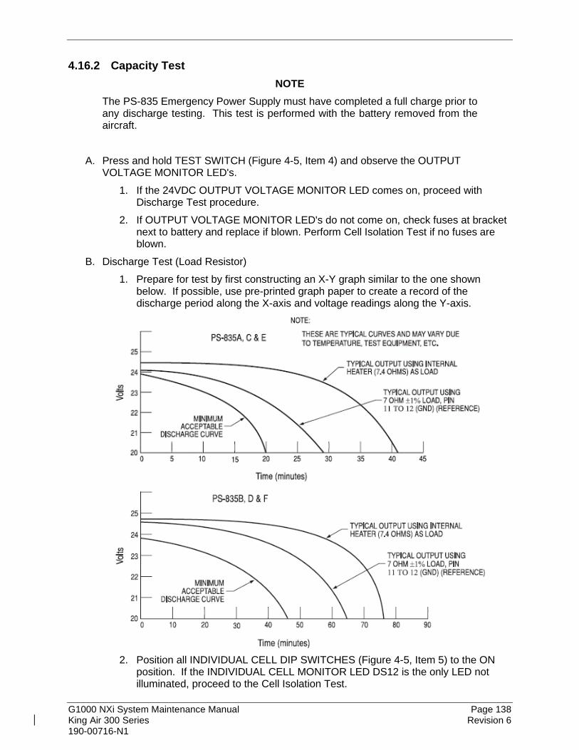
G1000 NXi System Maintenance Manual Page 138 King Air 300 Series Revision 6 190-00716-N1
4.16.2 Capacity Test NOTE
The PS-835 Emergency Power Supply must have completed a full charge prior to any discharge testing. This test is performed with the battery removed from the aircraft.
A. Press and hold TEST SWITCH (Figure 4-5, Item 4) and observe the OUTPUT VOLTAGE MONITOR LED's.
1. If the 24VDC OUTPUT VOLTAGE MONITOR LED comes on, proceed with Discharge Test procedure.
2. If OUTPUT VOLTAGE MONITOR LED's do not come on, check fuses at bracket next to battery and replace if blown. Perform Cell Isolation Test if no fuses are blown.
B. Discharge Test (Load Resistor) 1. Prepare for test by first constructing an X-Y graph similar to the one shown
below. If possible, use pre-printed graph paper to create a record of the discharge period along the X-axis and voltage readings along the Y-axis.
2. Position all INDIVIDUAL CELL DIP SWITCHES (Figure 4-5, Item 5) to the ON
position. If the INDIVIDUAL CELL MONITOR LED DS12 is the only LED not illuminated, proceed to the Cell Isolation Test.

G1000 NXi System Maintenance Manual Page 139 King Air 300 Series Revision 6 190-00716-N1
3. Connect Digital Voltmeter leads to J1 connector pins 11 (+) and 7 (-). 4. Connect the Load Resistor across J1 connector pins 11 (+) and 7 (-) and start
timing the discharge period with a stopwatch. 5. Monitor and plot voltage values at 10-minute intervals. 6. Note voltage on Digital Voltmeter at 48.0 minutes (PS-835D) or at 20.0 minutes
(PS-835C). This voltage must be greater than 20.0 Vdc. a. All INDIVIDUAL CELL MONITOR LED’s (Figure 4-5, Item 1) must remain
on. b. Any LED that does go OFF will represent a defective individual cell, which
must be replaced. 7. Remove the Load Resistor from J1 connector pins 11 (+) and 7 (-). 8. Position all INDIVIDUAL CELL DIP SWITCHES (Figure 4-5, Item 5) to the OFF
position. 9. Compare the voltage vs. time plot created during this test to that of curve
identified as typical for the External Load test method on the chart above. If the plot reveals a discharge curve that meets or exceeds the MINIMUM ACCEPTABLE DISCHARGE CURVE, the unit is considered satisfactory.
10. If unit discharge plot is satisfactory and no other failures were revealed, perform the Charging Procedure within 2 hours of completion of the discharge test. Return the unit into service.
4.16.3 Cell Isolation Test NOTE
No power should be applied to PS-835 Emergency Power Supply during test. This test is performed with the battery removed from the aircraft.
A. Press and hold TEST SWITCH (Figure 4-5, Item 4). If no OUTPUT VOLTAGE MONITOR LED's come on:
1. Position all INDIVIDUAL CELL DIP SWITCHES (Figure 4-5, Item 5) to the ON position.
2. Press and hold TEST SWITCH (Figure 4-5, Item 4) and observe the INDIVIDUAL CELL MONITOR LED's (Figure 4-5, Item 1).
a. If all INDIVIDUAL CELL MONITOR LED’s come on except DS12, the unit is damaged and requires repair at an authorized repair station.
b. If all INDIVIDUAL CELL MONITOR LED’s are on, a low-battery voltage condition exists.
B. Perform the Charging Procedure. See 4.16.4.
4.16.4 Charging Procedure (Constant-Voltage Charging Method) Locally manufacture a power cable using 16AWG wire and the appropriate mating connector. Include a Diode (15 Adc (min), 50.0 PIV or greater) to prevent battery discharge in case of loss

G1000 NXi System Maintenance Manual Page 140 King Air 300 Series Revision 6 190-00716-N1
of power from the power source. Using the external power supply apply 30.0 Vdc (10A maximum current limited) to J1 connector pins 11 (+) and 7 (-) and charge the unit for 16 hours. The batteries should reach 80% capacity within 1 hour and full charge at 16 hours.
Figure 4-6, Power Supply Connection
4.17 Rudder Boost Operational Check 1. Place the RUDDER BOOST switch to the OFF position. For Model 300 aircraft, set the
left and right bleed air control switches to the OPEN position. 2. Verify the amber RUD BOOST OFF annunciator on the aircraft’s caution and advisory
panel is illuminated. 3. Place the RUDDER BOOST switch to the RUDDER BOOST position. Verify the amber
RUD BOOST OFF annunciator on the aircraft caution and advisory panel is extinguished.
4. Pull GIA 1 primary and secondary circuit breakers. Verify RUD BOOST OFF annunciator is extinguished.
5. Pull GIA 2 circuit breaker. Verify RUD BOOST OFF annunciator illuminates. 6. Reset GIA 1 and GIA 2 circuit breakers. Verify RUD BOOST OFF annunciator
extinguishes. 7. Pull the AFCS SERVO circuit breaker. Verify RUD BOOST OFF annunciator
illuminates. 8. Reset AFCS SERVO circuit breaker. Verify RUD BOOST OFF annunciator extinguishes. 9. Press and hold the AP/DISC switch on the pilot’s control wheel and verify RUD BOOST
OFF annunciator illuminates. 10. Release the AP/DISC switch and verify the RUD BOOST OFF annunciator extinguishes. 11. Repeat steps 9-10 for the copilot’s control wheel.
NOTE
Steps 12-15 are only applicable to Model 300 aircraft.
12. Place the L BLEED AIR CONTROL SWITCH in the PNEU & ENVIR OFF position. Verify RUD BOOST OFF annunciator illuminates.
13. Place the L BLEED AIR CONTROL SWITCH in the OPEN position. Verify RUD BOOST OFF annunciator extinguishes.
14. Place the R BLEED AIR CONTROL SWITCH in the PNEU & ENVIR OFF position. Verify RUD BOOST OFF annunciator illuminates.
15. Place the R BLEED AIR CONTROL SWITCH in the OPEN position. Verify RUD BOOST OFF annunciator extinguishes.

G1000 NXi System Maintenance Manual Page 141 King Air 300 Series Revision 6 190-00716-N1
4.18 Exterior Skin Inspection Around Antennas Perform a visual inspection of the exterior skin for cracks and loose and missing fasteners in an area at least 1-inch around the following antennas:
• GA 36 GPS antenna
• GA 37 GPS/XM antenna
• GA 58 Traffic Antenna, Upper (if Garmin traffic system is installed)
• GA 58 Traffic Antenna, Lower (if Garmin traffic system is installed)
• Transponder Antenna, Upper #1 (if Garmin GTX 33D or GTX 3000 transponder is installed)
• Transponder Antenna, Upper #2 (if Garmin GTX 33D or GTX 3000 transponder is installed)
• Iridium Antenna (if Garmin GSR 56 satellite transceiver is installed)
• Wi-Fi Antenna (if Garmin GDL 59 Wi-Fi data link is installed) The antennas do not need to be removed to perform this inspection.
Figure 4-7, Exterior Skin Inspection Around Antennas
Should damage be detected in any structural component during this inspection, all adjacent structures must be carefully investigated for indications of related damage. All damage must be repaired using data obtained from the Structural Inspection and Repair Manual (SIRM), Beechcraft Repair Design Office (RDO), or other approved sources.

G1000 NXi System Maintenance Manual Page 142 King Air 300 Series Revision 6 190-00716-N1
5. TROUBLESHOOTING This section provides instructions and guidance for G1000 system troubleshooting as installed in the King Air 300 Series.
IMPORTANT! Sections 6, 7 and 9 provide detailed instructions on equipment removal, replacement, configuration, and return-to-service testing. Anytime a G1000 component or LRU is removed, swapped, or replaced, the technician must follow the procedures given in Sections 6, 7 and 9 to ensure proper operation of the system.
Troubleshoot the G1000 system by first identifying, then isolating the specific failure to the responsible LRU. There are several indications that the G1000 presents to the pilot or technician, showing overall system condition. A course of action should be determined based on the information presented on the display. This section shows possible scenarios likely to be encountered during normal operation and gives troubleshooting guidance to the technician to resolve problems.
Figure 5-1, Aux – System Status Page

G1000 NXi System Maintenance Manual Page 143 King Air 300 Series Revision 6 190-00716-N1
The Aux – System Status page displays the following information for each LRU and sub-function:
• Status: A green check is displayed for properly operating LRUs. A red ‘x’ appears when an internal LRU fault is detected and it has taken itself offline, or if the MFD cannot communicate with the LRU.
• Serial Number: Each LRU serial number is displayed (functions such as GPS and GS are contained within an LRU; therefore, serial numbers are not shown for these).
• Current SW Version Loaded. When troubleshooting, first check to ensure that each LRU status is ‘green’ and that the correct software is loaded in each unit. Additional airframe and database information is also displayed on this page.
5.1 System Annunciations If data fields become invalid due to an LRU failure, the PFD/MFD typically annunciates the failure with a large red X, as shown in Figure 5-2.
Figure 5-2, System Annunciations
5.1.1 Failed Path Messages The following message indicates there is a data path connected to the GDU (PFD1, PFD1, or MFD) or the GIA (1 or 2) that has failed. FAILED PATH – A data path has failed. The FAILED PATH message is triggered by a timeout of any one digital channel. The channels that are checked are listed on these pages in config mode:
1) GDU RS-232 / ARINC 429 CONFIG (PFD1/2, and MFD) 2) GIA RS-232 / ARINC 429 CONFIG (GIA1 and GIA2)

G1000 NXi System Maintenance Manual Page 144 King Air 300 Series Revision 6 190-00716-N1
3) GIA CAN / RS-485 CONFIGURATION (GIA1 and GIA2)
IMPORTANT! Once the FAILED PATH message has been triggered, it will remain on the list of messages until the next power cycle. This latching was implemented so that for intermittent failures, the message would remain at the end of the flight (to alert maintenance crew). Also, this keeps the crew from having to acknowledge message repeatedly in the case of intermittent failures.
The box next to each channel indicates the current status of the channel per the below:
• Red X = data path is known to be failed
• Amber question mark (?) = data path status is unknown
• Green checkmark ()= data path is known to be good The applicable data paths can be verified by viewing the following configuration mode pages.
5.1.1.1 GDU RS-232 / ARINC 429 CONFIG Page PFD 1 RS-232
Channel LRU Indicator Status
CHNL 2 GMC 710
Green PFD1/GMC 710 data path is functioning correctly.
Red
PFD1/GMC 710 data path is not functioning correctly. • Verify GMC710 is powered on.
o If GMC 710 will not power on, remove unit and verify power and ground are present at the GMC connector. If power or ground is not present,
troubleshoot aircraft wiring for faults. If power and ground are present,
replace GMC 710. • Load PFD1 and GMC 710 configuration files. • Swap PFD1and PFD2 to confirm if the problem is in
the original PFD1. o Replace original PFD1 if box turns green after
swapping displays. • Check the PFD1/GMC 710 interconnect wiring for
faults. Replace GMC 710 if problem remains.
Amber PFD1/GMC 710 data path functionality is unknown. Reload PFD1 configuration file.

G1000 NXi System Maintenance Manual Page 145 King Air 300 Series Revision 6 190-00716-N1
PFD 1 ARINC 429
Channel LRU Indicator Status
IN 1
GRS 77 or GRS 7800 or GSU 75
#1
Green PFD1/GRS or GSU 1 data path is functioning correctly.
Red
PFD1/GRS or GSU 1 data path is not functioning correctly. • Verify GRS or GSU 1 status is “OK” using the Aux –
System Status page on the MFD. If it is not, correct condition before proceeding, reference GRS troubleshooting sections.
o Swap GRS1 and GRS2 (no reconfiguration required) to confirm if the problem is in the original GRS1.
o Replace original GRS1 if box turns green after swapping units.
• Load PFD1 configuration file. • Swap PFD1 and PFD2 to confirm if the problem is in
the original PFD1. o Replace original PFD1 if box turns green after
swapping displays. • Swap GRS1 and GRS2 (no reconfiguration required)
to confirm if the problem is in the original GRS1. o Replace original GRS1 if box turns green after
swapping units. Check the PFD1/ GRS or GSU 1 interconnect wiring for faults.
Amber PFD1/GRS or GSU 1 data path functionally is unknown. Reload PFD1 configuration file.
IN 2 GDC7400 or GDC 72
#1
Green PFD1/GDC #1 data path is functioning correctly
Red
PFD1/GDC #1 data path is not functioning correctly. • Verify GDC #1 status is “OK” using the Aux – System
Status page on the MFD. If it is not, correct condition before proceeding, reference GDC troubleshooting sections.
• Load PFD1 and GDC #1 configuration files. • Swap PFD1 and PFD2 to confirm if the problem is in
the original PFD1. o Replace original PFD1 if box turns green after
swapping displays. • Check the PFD1/GDC #1 interconnect wiring for faults. Replace GDC #1 if problem remains.
Amber PFD1/GDC #1 data path functionality is unknown. Reload PFD1 configuration file.

G1000 NXi System Maintenance Manual Page 146 King Air 300 Series Revision 6 190-00716-N1
PFD 2 RS-232
Channel LRU Indicator Status
CHNL 2 GMC 710
Green PFD2/GMC 710 data path is functioning correctly.
Red
PFD2/GMC 710 data path is not functioning correctly. • Verify GMC 710 is powered on.
o If GMC 710 will not power on, remove unit and verify power and ground are present at the GMC connector. If power or ground is not present,
troubleshoot aircraft wiring for faults. If power and ground are present,
replace GMC 710. • Load PFD2 and GMC 710 configuration files. • Swap PFD2 and PFD1 to confirm if the problem is in
the original PFD2. o Replace original PFD2 if box turns green after
swapping displays.
• Check the PFD2/GMC 710 interconnect wiring for faults.
Replace GMC 710 if problem remains.
Amber PFD2/GMC 710 data path functionality is unknown. Reload PFD2 configuration file.

G1000 NXi System Maintenance Manual Page 147 King Air 300 Series Revision 6 190-00716-N1
PFD 2 ARINC 429
Channel LRU Indicator Status
IN 1
GRS 77 or GRS 7800 or GSU 75
#2
Green PFD2/GRS or GSU 2 data path is functioning correctly.
Red
PFD2/GRS or GSU 2 data path is not functioning correctly. • Verify GRS or GSU 2 status is “OK” using the Aux –
System Status page on the MFD. If it is not, correct condition before proceeding, reference GRS troubleshooting sections.
o Swap GRS1 and GRS2 (no reconfiguration required) to confirm if the problem is in the original GRS1.
o Replace original GRS1 if box turns green after swapping units.
• Load PFD2 configuration file. • Swap PFD2 and PFD1 to confirm if the problem is in
the original PFD2. o Replace original PFD2 if box turns green after
swapping displays. • Swap GRS1 and GRS2 (no reconfiguration required)
to confirm if the problem is in the original GRS1. o Replace original GRS1 if box turns green after
swapping units. • Check the PFD2/GRS or GSU 2 interconnect wiring for
faults.
Amber PFD2/GRS or GSU 2 data path functionality is unknown. Reload PFD2 configuration file.
IN 2 GDC 7400
or GDC 72 #2
Green PFD2/GDC #2 data path is functioning correctly.
Red
PFD2/GDC #2 data path is not functioning correctly. • Verify GDC #2 status is “OK” using the Aux – System
Status page on the MFD. If it is not, correct condition before proceeding, reference GDC troubleshooting sections.
• Load PFD2 and GDC #2 configuration files. • Swap PFD2 and PFD1 to confirm if the problem is in
the original PFD2. o Replace original PFD2 if box turns green after
swapping displays. • Check the PFD2/GDC #2 interconnect wiring for faults. Replace GDC #2 if problem remains.
Amber PFD2/GDC #2 data path functionality is unknown. Reload PFD2 configuration file.

G1000 NXi System Maintenance Manual Page 148 King Air 300 Series Revision 6 190-00716-N1
MFD1 RS-232
Channel LRU Indicator Status
CHNL 1 GCU 477
Green MFD1/GCU 477 data path is functioning correctly.
Red
MFD1/GCU 477 data path is not functioning correctly. • Verify GCU 477 is powered on.
o If GCU 477 will not power on, remove unit and verify power and ground are present at the GCU connector. If power or ground is not present,
troubleshoot aircraft wiring for faults. If power and ground are present,
replace GCU 477. • Load MFD1 and GCU 477 configuration files. • Check the MFD1/GCU 477 interconnect wiring for
faults. • Replace GCU 477. Replace MFD if problem remains.
Amber MFD1/GCU data path functionality is unknown. Reload MFD1 configuration file.

G1000 NXi System Maintenance Manual Page 149 King Air 300 Series Revision 6 190-00716-N1
5.1.1.2 GIA RS-232 / ARINC 429 CONFIG Page GIA1 RS-232
Channel LRU Indicator Status
CHNL 1 GDC 72 or GDC7400
#1
Green GIA1/GDC #1 data path is functioning correctly.
Red
GIA1/GDC #1 data path is not functioning correctly. • Load GIA1 and GDC #1 configuration files. • Swap GIA1 and GIA2, reconfigure both GIA’s to their
new locations to confirm if the problem is in the original GIA1.
o Replace original GIA1 if box turns green after swapping units.
• Check the GIA1/GDC #1 interconnect wiring for faults. Replace GDC #1 if problem remains.
Amber GIA1/GDC #1 data path functionality is unknown. Reload GIA1 configuration files.
CHNL 2
GRS 77 or GRS 7800 or GRS 79 #2 (output
only)
White N/A GIA1/GRS or GSU 2 output data path is not monitored. A white N/A box is normal.
CHNL 5
GTX 33ES or GTX 3000 or
GTX 3x5 #1
Green GIA1/GTX 1 data path is functioning correctly.
Red
GIA1/GTX 1 data path is not functioning correctly. • Load GIA1 and GTX 1 configuration files. • Swap GIA1 and GIA2, reconfigure both GIA’s to their
new locations to confirm if the problem is in the original GIA1.
o Replace original GIA1 if box turns green after swapping units.
• Check the GIA1/GTX 1 interconnect wiring for faults. Replace GTX 1 if problem remains.
Amber GIA1/GTX 1 data path functionality is unknown. Reload GIA1 configuration files.

G1000 NXi System Maintenance Manual Page 150 King Air 300 Series Revision 6 190-00716-N1
GIA1 RS-232 (continued)
Channel LRU Indicator Status
CHNL 6
GRS 77 or GRS 7800 or GRS 79
#1
Green GIA1/GRS or GSU 1 data path is functioning correctly.
Red
GIA1/ GRS or GSU 1 data path is not functioning correctly. • Load GIA1 configuration files. • Swap GIA1 and GIA2, reconfigure both GIA’s to their
new locations to confirm if the problem is in the original GIA1.
o Replace original GIA1 if box turns green after swapping units.
• Swap GRS1 and GRS2 (no reconfiguration required) to confirm if the problem is in the original GRS1.
o Replace original GRS1 if box turns green after swapping units.
Check the GIA1/GRS or GSU 1 interconnect wiring for faults.
Amber GIA1/GRS or GSU 1 data path functionality is unknown. Reload GIA1 configuration files.
CHNL 7
GMA 1347D or
GMA 1360D #1
Green GIA1/GMA1 data path is functioning correctly.
Red
GIA1/GMA1 data path is not functioning correctly. • Load GIA1 and GMA1 configuration files. • Swap GMA1 and GMA2, reconfigure both GMA’s to
their new locations, to confirm if the problem is in the original GMA1.
o Replace original GMA1 if box turns green after swapping units.
• Swap GIA1 and GIA2, reconfigure both GIA’s to their new locations to confirm if the problem is in the original GIA1.
o Replace original GIA1 if box turns green after swapping units.
Check the GIA1/GMA1 interconnect wiring for faults.
Amber GIA1/GMA1 data path functionality is unknown. Reload GIA1 configuration files.

G1000 NXi System Maintenance Manual Page 151 King Air 300 Series Revision 6 190-00716-N1
GIA1 ARINC 429
Channel LRU Indicator Status
IN 2
GRS 77 or GRS 7800 or GSU 75
#2
Green GIA1/GRS or GSU 2 data path is functioning correctly.
Red
GIA1/GRS or GSU 2 data path is not functioning correctly.
• Reload GIA1 configuration file.
• Swap GIA1 and GIA2, reconfigure both GIA’s to their new locations to confirm if the problem is in the original GIA1.
o Replace original GIA1 if box turns green after swapping units.
• Swap GRS1 and GRS2 (no reconfiguration required) to confirm if the problem is in the original GRS2.
o Replace original GRS2 if box turns green after swapping units.
• Check the GIA1/GRS or GSU 2 interconnect wiring for faults.
Amber GIA1/GRS or GSU 2 data path functionality is unknown. Reload GIA1 configuration files.
IN 5 GDC7400 #1
Green GIA1/GDC1 data path is functioning correctly.
Red
GIA1/GDC1 data path is not functioning correctly.
• Load GIA1 and GDC1 configuration files.
• Swap GIA1 and GIA2, reconfigure both GIA’s to their new locations to confirm if the problem is in the original GIA1.
o Replace original GIA1 if box turns green after swapping units.
• Check the GIA1/GDC1 interconnect wiring for faults. Replace GDC1 if problem remains.
Amber GIA1/GDC1 data path functionality is unknown. Reload GIA1 configuration files.

G1000 NXi System Maintenance Manual Page 152 King Air 300 Series Revision 6 190-00716-N1
Channel LRU Indicator Status
IN 6
GRS 77 or GRS 7800 or GSU 75
#1
Green GIA1/GRS or GSU 1 data path is functioning correctly.
Red
GIA1/GRS or GSU 1 data path is not functioning correctly.
• Load GIA1 configuration files.
• Swap GIA1 and GIA2, reconfigure both GIA’s to their new locations to confirm if the problem is in the original GIA1.
o Replace original GIA1 if box turns green after swapping units.
• Swap GRS1 and GRS2 (no reconfiguration required, ref. GRS Configuration and Testing sections) to confirm if the problem is in the original GRS1.
o Replace original GRS1 if box turns green after swapping units.
• Check the GIA1/GRS or GSU 1 interconnect wiring for faults.
Amber GIA1/GRS or GSU 1 data path functionality is unknown. Reload GIA1 configuration files.

G1000 NXi System Maintenance Manual Page 153 King Air 300 Series Revision 6 190-00716-N1
GIA2 RS-232
Channel LRU Indicator Status
CHNL 1 GDC 72 or GDC 7400 #2
Green GIA2/GDC2 data path is functioning correctly.
Red
GIA2/GDC2 data path is not functioning correctly. • Load GIA2 and GDC2 configuration files. • Swap GIA2 and GIA1, reconfigure both GIA’s
to their new locations to confirm if the problem is in the original GIA1.
o Replace original GIA2 if box turns green after swapping units.
• Check the GIA1/GDC2 interconnect wiring for faults.
Replace GDC #2 if problem remains.
Amber GIA2/GDC2 data path functionality is unknown. Reload GIA2 configuration files.
CHNL 2 GRS 77 or GRS 7800 or GRS 79 #1 (output
only) White N/A GIA2/GRS or GSU 1 output data path is not
monitored. A white N/A box is normal.
CHNL 5 GTX 33ES or
GTX3000 or GTX 3x5 #2
Green GIA2/GTX 2 data path is functioning correctly.
Red
GIA2/GTX 2 data path is not functioning correctly. • Load GIA2 and GTX2 configuration files. • Swap GIA2 and GIA1, reconfigure both GIA’s
to their new locations to confirm if the problem is in the original GIA1.
o Replace original GIA2 if box turns green after swapping units.
• Check the GIA2/GTX 2 interconnect wiring for faults.
Replace GTX 2 if problem remains.
Amber GIA2/GTX 2 data path functionality is unknown. Reload GIA2 configuration files.

G1000 NXi System Maintenance Manual Page 154 King Air 300 Series Revision 6 190-00716-N1
GIA2 RS-232 (continued)
Channel LRU Indicator Status
CHNL 6
GRS 77 or GRS 7800 or GRS 79
#2
Green GIA2/GRS or GSU 2 data path is functioning correctly.
Red
GIA2/GRS or GSU 2 data path is not functioning correctly. • Load GIA2 configuration files. • Swap GIA2 and GIA1, reconfigure both GIA’s to their
new locations to confirm if the problem is in the original GIA1.
o Replace original GIA2 if box turns green after swapping units.
• Swap GRS2 and GRS1 (no reconfiguration required) to confirm if the problem is in the original GRS2.
o Replace original GRS2 if box turns green after swapping units.
Check the GIA2/GRS or GSU 2 interconnect wiring for faults.
Amber GIA2/GRS or GSU 2 data path functionality is unknown. Reload GIA2 configuration files.
CHNL 7
GMA 1347D or
GMA 1360D #2
Green GIA2/GMA2 data path is functioning correctly.
Red
GIA2/GMA2 data path is not functioning correctly. • Load GIA2 and GMA2 configuration files. • Swap GMA2 and GMA1, reconfigure both GMA’s to
their new locations to confirm if the problem is in the original GMA2.
o Replace original GMA2 if box turns green after swapping units.
• Swap GIA2 and GIA1, reconfigure both GIA’s to their new locations to confirm if the problem is in the original GIA2.
o Replace original GIA2 if box turns green after swapping units.
Check the GIA1/GMA2 interconnect wiring for faults.
Amber GIA1/GMA2 data path functionality is unknown. Reload GIA2 configuration files.

G1000 NXi System Maintenance Manual Page 155 King Air 300 Series Revision 6 190-00716-N1
GIA2 ARINC 429
Channel LRU Indicator Status
IN 2
GRS 77 or GRS 7800 or GSU 75
#1
Green GIA2/GRS1 data path is functioning correctly.
Red
GIA2/GRS or GSU 1 data path is not functioning correctly.
• Reload GIA2 configuration file.
• Swap GIA2 and GIA1, reconfigure both GIA’s to their new locations to confirm if the problem is in the original GIA2.
o Replace original GIA2 if box turns green after swapping units.
• Swap GRS1 and GRS2 (no reconfiguration required) to confirm if the problem is in the original GRS1.
o Replace original GRS1 if box turns green after swapping units.
• Check the GIA2/GRS or GSU 1 interconnect wiring for faults.
Amber GIA2/GRS or GSU 1 data path functionality is unknown. Reload GIA2 configuration files.
IN 5 GDC7400 #2
Green GIA2/GDC2 data path is functioning correctly.
Red
GIA2/GDC2 data path is not functioning correctly.
• Load GIA2 and GDC2 configuration files.
• Swap GIA2 and GIA1, reconfigure both GIA’s to their new locations to confirm if the problem is in the original GIA2.
o Replace original GIA2 if box turns green after swapping units.
• Check the GIA2/GDC2 interconnect wiring for faults. Replace GDC #2 if problem remains.
Amber GIA2/GDC2 data path functionality is unknown. Reload GIA2 configuration files.

G1000 NXi System Maintenance Manual Page 156 King Air 300 Series Revision 6 190-00716-N1
Channel LRU Indicator Status
IN 6
GRS 77 or GRS 7800 or GSU 75
#2
Green GIA2/GRS or GSU 2 data path is functioning correctly.
Red
GIA2/GRS or GSU 2 data path is not functioning correctly.
• Load GIA2 configuration files.
• Swap GIA2 and GIA1, reconfigure both GIA’s to their new locations to confirm if the problem is in the original GIA2.
o Replace original GIA2 if box turns green after swapping units.
• Swap GRS2 and GRS1 (no reconfiguration required) to confirm if the problem is in the original GRS2.
o Replace original GRS2 if box turns green after swapping units.
• Check the GIA2/GRS or GSU 2 interconnect wiring for faults.
Amber GIA2/GRS or GSU 2 data path functionality is unknown. Reload GIA2 configuration files.
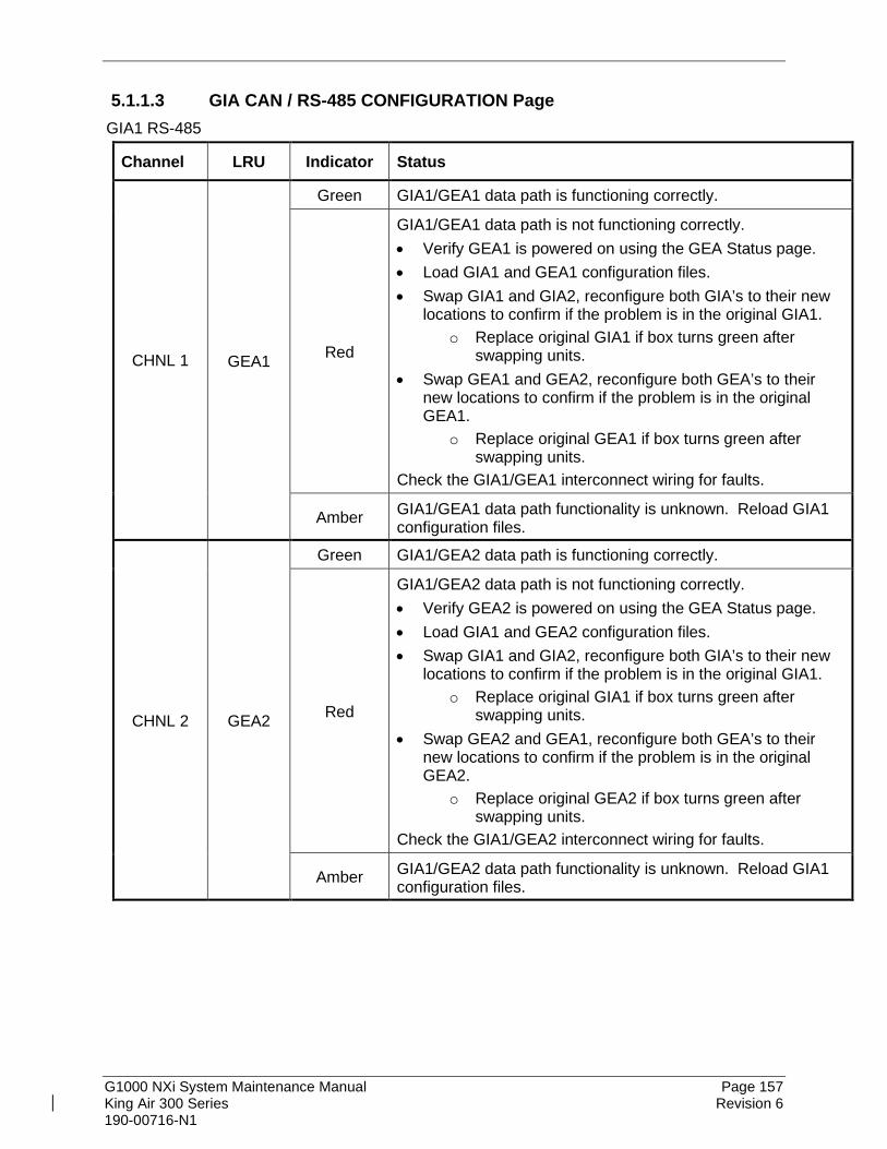
G1000 NXi System Maintenance Manual Page 157 King Air 300 Series Revision 6 190-00716-N1
5.1.1.3 GIA CAN / RS-485 CONFIGURATION Page GIA1 RS-485
Channel LRU Indicator Status
CHNL 1 GEA1
Green GIA1/GEA1 data path is functioning correctly.
Red
GIA1/GEA1 data path is not functioning correctly. • Verify GEA1 is powered on using the GEA Status page. • Load GIA1 and GEA1 configuration files. • Swap GIA1 and GIA2, reconfigure both GIA’s to their new
locations to confirm if the problem is in the original GIA1. o Replace original GIA1 if box turns green after
swapping units. • Swap GEA1 and GEA2, reconfigure both GEA’s to their
new locations to confirm if the problem is in the original GEA1.
o Replace original GEA1 if box turns green after swapping units.
Check the GIA1/GEA1 interconnect wiring for faults.
Amber GIA1/GEA1 data path functionality is unknown. Reload GIA1 configuration files.
CHNL 2 GEA2
Green GIA1/GEA2 data path is functioning correctly.
Red
GIA1/GEA2 data path is not functioning correctly. • Verify GEA2 is powered on using the GEA Status page. • Load GIA1 and GEA2 configuration files. • Swap GIA1 and GIA2, reconfigure both GIA’s to their new
locations to confirm if the problem is in the original GIA1. o Replace original GIA1 if box turns green after
swapping units. • Swap GEA2 and GEA1, reconfigure both GEA’s to their
new locations to confirm if the problem is in the original GEA2.
o Replace original GEA2 if box turns green after swapping units.
Check the GIA1/GEA2 interconnect wiring for faults.
Amber GIA1/GEA2 data path functionality is unknown. Reload GIA1 configuration files.

G1000 NXi System Maintenance Manual Page 158 King Air 300 Series Revision 6 190-00716-N1
Channel LRU Indicator Status
CHNL 4 GFC 700
Green GIA1/GFC 700 data path is functioning correctly.
Red
GIA1/GFC 700 data path is not functioning correctly. • Load GIA1 configuration files, GIA Gains file and GSA
software and gains file (if LRU and Card versions are different).
Reference GFC section for further troubleshooting.
Amber GIA1/GFC 700 data path functionality is unknown. Reload GIA1 configuration files.
GIA2 RS-485
Channel LRU Indicator Status
CHNL 1 GEA1
Green GIA2/GEA1 data path is functioning correctly.
Red
GIA2/GEA1 data path is not functioning correctly. • Verify GEA1 is powered on using the GEA Status
page. • Load GIA2 and GEA1 configuration files. • Swap GIA2 and GIA1, reconfigure both GIA’s to their
new locations to confirm if the problem is in the original GIA2.
o Replace original GIA2 if box turns green after swapping units.
• Swap GEA1 and GEA2, reconfigure both GEA’s to their new locations to confirm if the problem is in the original GEA1.
o Replace original GEA1 if box turns green after swapping units.
Check the GIA2/GEA1 interconnect wiring for faults.
Amber GIA2/GEA1 data path functionality is unknown. Reload GIA2 configuration files.

G1000 NXi System Maintenance Manual Page 159 King Air 300 Series Revision 6 190-00716-N1
Channel LRU Indicator Status
CHNL 2 GEA2
Green GIA2/GEA2 data path is functioning correctly.
Red
GIA2/GEA2 data path is not functioning correctly. • Verify GEA2 is powered on using the GEA Status
page. • Load GIA2 and GEA2 configuration files. • Swap GIA2 and GIA1, reconfigure both GIA’s to their
new locations to confirm if the problem is in the original GIA2.
o Replace original GIA2 if box turns green after swapping units.
• Swap GEA2 and GEA1, reconfigure both GEA’s to their new locations to confirm if the problem is in the original GEA2.
o Replace original GEA2 if box turns green after swapping units.
Check the GIA2/GEA2 interconnect wiring for faults.
Amber GIA2GEA2 data path functionality is unknown. Reload GIA2 configuration files.
CHNL 4 GFC 700
Green GIA2/GFC 700 data path is functioning correctly.
Red
GIA2/GFC 700 data path is not functioning correctly.
• Load GIA2 configuration files, GIA Gains file and GSA software and gains file (if LRU and Card versions are different).
Reference GFC section for further troubleshooting.
Amber GIA2/GFC 700 data path functionality is unknown. Reload GIA2 configuration files.

G1000 NXi System Maintenance Manual Page 160 King Air 300 Series Revision 6 190-00716-N1
5.1.2 System Failure Troubleshooting The following table provides basic troubleshooting guidance for LRU failures. Refer to G1000 Wiring Diagram, listed in Table 1-1, as needed to verify interconnects.
Invalid Data Field Associated LRU(s) Solution
Low Speed Awareness Band permanently displayed
GDU
• With aircraft weight on wheels and the G1000 in Configuration Mode, check that the RH GEAR ON GROUND Discrete In indication for GIA2, on GIA I/O CONFIGURATION page is illuminated.
• With aircraft weight on wheels and the G1000 in Configuration Mode, check that the LH GEAR ON GROUND Discrete In indication for GIA1, on GIA I/O CONFIGURATION page is illuminated.
• If both indications are illuminated Green, switch GIA1 and GIA2, to verify location of problem: If problem is resolved, replace faulty unit. If indication is not illuminated, check for wiring faults
between the GIAs and aircraft squat switch system.
Low Speed Awareness Band permanently inhibited
GDU
• With aircraft weight on wheels and the G1000 in Configuration Mode, check that the RH GEAR ON GROUND Discrete In indication for GIA2, on GIA I/O CONFIGURATION page is illuminated.
• With aircraft weight on wheels and the G1000 in Configuration Mode, check that the LH GEAR ON GROUND Discrete In indication for GIA1, on GIA I/O CONFIGURATION page is illuminated.
• If both indications are illuminated Green, switch GIA1 and GIA2, to verify location of problem: If problem is resolved, replace faulty unit. If indication is not illuminated, check for wiring faults
between the GIAs and aircraft squat switch system.
NAV1 & COM1
GIA1
• Check configuration settings for GIA1 and PFD1. • Swap GIA1 and GIA2, to verify location of problem:
If problem follows GIA1, replace GIA1. • Check Ethernet interconnect from GIA1 to PFD1.
If problem persists, replace PFD.

G1000 NXi System Maintenance Manual Page 161 King Air 300 Series Revision 6 190-00716-N1
Invalid Data Field Associated LRU(s) Solution
NAV2 & COM2
GIA2
• Check configuration settings for GIA2 and PFD2. • Swap GIA1 and GIA2, to verify location of problem:
If problem follows GIA2, replace GIA2. • Check Ethernet interconnect from GIA2 to PFD2.
If problem persists, replace PFD.
GPS LOI
GIA1 or GIA2
• Ensure that a cell phone or a device using cell phone technology is not turned on (even in a monitoring state) in the cabin.
• Check GPS1 and GPS2 signal strength on Aux – GPS Status page. Refer to GIA GPS section if GPS cannot acquire a position lock for troubleshooting.
• Check corresponding GPS antenna and cable for faults. • Check Ethernet interconnect between the PFD1 to GIA1 or
PFD2 to GIA2 for faults. • Swap GIA1 and GIA2, to verify location of problem:
If problem follows the GIA, replace the GIA. If problem persists, replace the PFD1 or PFD2.
XPDR FAIL
GTX 335R, GTX 345R,
GTX 33( ), or GTX 3000
• Check GTX 335R/345R/33/33D/3000 configuration settings for GIA1 and GIA2.
• Check GTX 335R/345R/33D/3000 and GIA1 interconnect. • Check GTX 335R/345R/33D/3000 and GIA2 interconnect. • Perform a SET>ACTV configuration reset on the GTX Config
page for each GTX, and verify the aircraft registration is present.
• Replace GTX 335R/345R/33/33D/3000. If problem persists, replace GIA.
TAS FAIL AIRSPEED FAIL ALTITUDE FAIL
VERT SPEED FAIL
GSU 75B or GDC 7400
• Inspect GSU 75B/GDC 7400 pitot/static plumbing integrity. • Inspect pitot/static ports and associated equipment for faults. • For TAS failure, also check GTP 59 probe. • Check GSU 75B/GDC 7400 configuration settings for the
PFDs, MFD, GIA1, and GIA2. If problem persists, replace the GSU 75B/GDC 7400.
OAT
GTP 59 GSU 75B, or GDC 7400
• Check OAT probe wiring and connectors for faults. • Replace GSU 75B/GDC 7400 with a known good unit:
If problem persists, replace the GTP 59.

G1000 NXi System Maintenance Manual Page 162 King Air 300 Series Revision 6 190-00716-N1
Invalid Data Field Associated LRU(s) Solution
ATTITUDE FAIL
GSU 75B, GRS 77, or GRS 7800
• Ensure that a cell phone or a device using cell phone technology is not turned on (even in a monitoring state) in the cabin.
• Cycle GSU 75B, GRS 77, or GRS 7800 power to restart initialization.
• Ensure GSU 75B, GRS 77, or GRS 7800 connecter is secure and proper wire harness strain relief is provided.
• Ensure the GSU 75B, GRS 77, or GRS 7800 is fastened down tightly in its mounting rack and that the mounting rack is not loose (CAUTION - do not loosen the mounting rack hardware to the airframe shelf or the aircraft will need to be re-leveled and the PITCH/ROLL OFFSET procedure performed).
• Ensure GPS has acquired at least four satellites, has a 3D navigation solution, and a DOP of less than 5.0. This is particularly important for an ATTITUDE FAIL that appears during ground operation only.
• Perform an Engine Run-Up Test to check if engine vibration is causing the GSU 75B, GRS 77, or GRS 7800 to go offline.
• Load configuration files to the PFD, MFD, GIA1, and GIA2. • Calibrate the GSU 75B, GRS 77, or GRS 7800 (Pitch/Roll
Offset and Magnetometer Calibration). • Replace GSU 75B, GRS 77, or GRS 7800.
If problem persists replace GSU 75B, GRS 77, or GRS 7800 configuration module.
Contact Garmin Aviation Product Support if condition continues after replacing the GSU 75B, GRS 77, or GRS 7800 and config module for additional assistance.

G1000 NXi System Maintenance Manual Page 163 King Air 300 Series Revision 6 190-00716-N1
Invalid Data Field Associated LRU(s) Solution
HDG FAIL
GSU 75B, GRS 77, or GRS 7800
&
GMU 44
• Ensure metal objects (tool boxes, power carts, etc.) are not interfering with the magnetometer and aircraft is not in hangar, near other buildings, parked over metal drainage culverts or on hard surfaces that may contain steel reinforcements
• The GMU 44 magnetometers located in the tail cone are vulnerable to magnetized rudder torque tube lower fittings and control rod ends. This magnetism may be caused by an improperly functioning aircraft static discharge system which is dependent on static dischargers (wicks) and electrical bonding of the static dischargers and surrounding structure. The bonding straps on the elevators and rudder should be visually inspected to verify they are not missing, broken or frayed. Refer to the King Air 300 Series Maintenance Manual, chapter 23-60-00, to verify the following items are within specification:
1. The resistance from the tip to the base of each static discharger
2. The resistance between the base of each static discharger and the surface to which it is attached
3. The resistance between the elevators/rudder and the airplane structure
• Ensure that a cell phone or a device using cell phone technology is not turned on (even in a monitoring state) in the cabin.
• Cycle power after moving aircraft away from metal objects to determine if metal objects were the source of the interference. Allow up to five minutes for the heading to reinitialize.
• Perform a Magnetometer Interference Test to check for interference from onboard electrical system components (e.g. NAV lights). Pay particular attention to any new electrical devices that have been installed since the aircraft was new. Correct any discrepancies that do not allow this test to pass before continuing.
• Ensure GSU 75B, GRS 77, or GRS 7800 and GMU 44 connectors are secure.
• Check the wiring and any inline connectors between the GSU/GRS and GMU for faults.
• Recalibrate the GMU 44, • Load configuration files to the PFD1, PFD2, GIA1, and
GIA2 If problem persists replace the GMU 44. If problem persists, replace the GSU 75B, GRS 77, or
GRS 7800.
GSU 75B, GRS 77, or GRS 7800
&
GMU 44
• If this message persists longer than five minutes, perform AHRS calibration procedures as described in Section 7.10.

G1000 NXi System Maintenance Manual Page 164 King Air 300 Series Revision 6 190-00716-N1
Invalid Data Field Associated LRU(s) Solution
Engine/Airframe Sensors (All Invalid)
GEA 71 or GEA 71B
&
GIA 63W or GIA 64E
• If software was loaded to a new GDU display, be sure that the user settings for the replaced display were cleared. Clear user settings by pressing the CLR key on the replaced display while applying power to it. Acknowledge the on-screen prompt by pressing the ENT key or the right-most softkey.
• Check for GEA related Alert messages on the PFD. Correct any Alerts concerning software or configuration errors by reloading software or configuration as noted.
• Verify GEA internal power supply, configuration, and calibration status in configuration mode. The internal power supply, configuration and
calibration boxes should be green. If they are red, replace the GEA.
• Verify internal, external, and reference voltages listed in the Main Analog and I/O A Analog boxes are not dashed out (does not include Aircraft Power 1 and 2). If any voltages are dashed out, replace the GEA.
• Ensure the GEA is online (green checkmark on the Aux – System Status page). If GEA is not online verify unit is receiving power at
the rack connector. Check the GIA/GEA interconnects for faults. Reload configuration files to both GIA’s and the GEA.
• If problem persists, replace the GEA.

G1000 NXi System Maintenance Manual Page 165 King Air 300 Series Revision 6 190-00716-N1
5.1.3 Engine/Airframe Instrument Failures The following table provides guidance for troubleshooting individual engine/airframe sensor failures. Be sure to also follow previous guidance given for the GEA. The technician should troubleshoot to isolate the fault by checking sensor-to-GEA wiring, replacing the suspect sensor, and finally by replacing the GEA. Replace one part at a time. Refer to Section 7.4.3 to check for correct operation of the sensors and GEA after any part has been replaced. Refer to G1000 Wiring Diagram and King Air 300 Series Maintenance Manual (listed in Table 1-1) as needed.
Invalid Field Sensor Possible Solutions (for applicable engine/system)
ITT • Check thermocouple cable. • Replace thermocouple cable. • Replace GEA.
Torque
• Check torque transmitter – GEA wiring. • Check power input to torque transmitter. • Replace torque transmitter. • Replace GEA.
Prop RPM
• Check prop tachometer – Signal Conditioner wiring. • Check Signal Conditioner – GEA wiring. • Check power input to Signal Conditioner. • Replace prop tachometer sensor. • Replace Signal Conditioner. Refer to Section 6.23. • Replace GEA.
Turbine RPM
• Check engine speed tachometer – Signal Conditioner wiring. • Check Signal Conditioner – GEA wiring. • Check power input to Signal Conditioner. • Replace engine speed tachometer sensor. • Replace Signal Conditioner. Refer to Section 6.23. • Replace GEA.
Fuel Flow
• Check Signal Conditioner unit wiring. • Check power input to Signal Conditioner • Replace fuel flow transmitter. • Replace Signal Conditioner. Refer to Section 6.23. • Replace GEA.
Oil Pressure • Check oil pressure sensor – GEA wiring. • Replace oil pressure sensor. • Replace GEA.
Oil Temperature • Check oil temperature sensor – GEA wiring. • Replace oil temperature sensor. • Replace GEA.

G1000 NXi System Maintenance Manual Page 166 King Air 300 Series Revision 6 190-00716-N1
5.1.4 ADF/DME Failure A DME or ADF failure is represented by the following red X’s. Refer to G1000 Wiring Diagram and King Air 300 Series Maintenance Manual (listed in Table 1-1,) as needed.
Invalid Field Sensor Solutions
or
ADF
• Ensure that GIA2 is properly functioning. • Reload the ADF option configurations. • Check for proper operation of the ADF receiver. Ensure that
the receiver is receiving power. • Check ADF – GIA2 interconnect. • For other failures of the ADF system, refer to King Air 300
Series Maintenance Manual, listed in Table 1-1.
DME
• Ensure that GIA1 is properly functioning. • Reload the DME option configurations. • Check for proper operation of the DME receiver. Ensure that
the receiver is receiving power. • Check DME – GIA1 interconnect. • For other failures of the DME system, refer to the King Air 300
Series Maintenance Manual, listed in Table 1-1.

G1000 NXi System Maintenance Manual Page 167 King Air 300 Series Revision 6 190-00716-N1
5.2 G1000 Alerting System
Figure 5-3, Alerts & Annunciations
The G1000 Alert System conveys alerts to the pilot using combinations of the following features: Alert Window:
The Alert window displays alert text messages. Pressing the Alerts softkey displays the Alerts window. Pressing the ALERTS softkey again removes the Alerts window from the display. Softkey Annunciation:
When the G1000 Alerting System issues an alert, the Alerts softkey is used as a flashing annunciation to accompany the alert. During the alert, the Alerts softkey label flashes between white letters on black to black letters on a white. The flashing continues until the alert is acknowledged by a press of the Alerts softkey. The alerts softkey remains black letters on white until the condition causing the alert is corrected, or a new alert triggers the flashing.
Figure 5-4, Alerts Softkey Annunciation System Failure Annunciations:
Typically, a large red X appears in windows when a failure is detected in the LRU providing the information to the window.
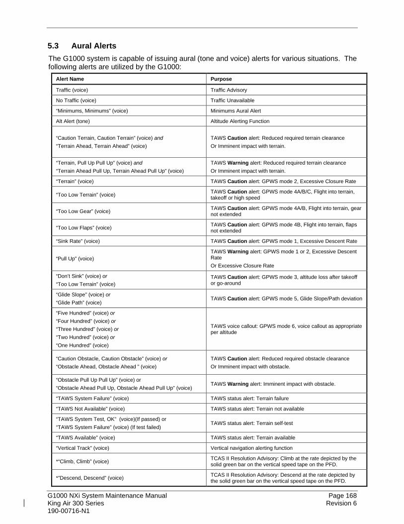
G1000 NXi System Maintenance Manual Page 168 King Air 300 Series Revision 6 190-00716-N1
5.3 Aural Alerts The G1000 system is capable of issuing aural (tone and voice) alerts for various situations. The following alerts are utilized by the G1000:
Alert Name Purpose
Traffic (voice) Traffic Advisory
No Traffic (voice) Traffic Unavailable
“Minimums, Minimums” (voice) Minimums Aural Alert
Alt Alert (tone) Altitude Alerting Function
“Caution Terrain, Caution Terrain” (voice) and “Terrain Ahead, Terrain Ahead” (voice)
TAWS Caution alert: Reduced required terrain clearance Or Imminent impact with terrain.
“Terrain, Pull Up Pull Up” (voice) and “Terrain Ahead Pull Up, Terrain Ahead Pull Up” (voice)
TAWS Warning alert: Reduced required terrain clearance Or Imminent impact with terrain.
“Terrain” (voice) TAWS Caution alert: GPWS mode 2, Excessive Closure Rate
“Too Low Terrain” (voice) TAWS Caution alert: GPWS mode 4A/B/C, Flight into terrain, takeoff or high speed
“Too Low Gear” (voice) TAWS Caution alert: GPWS mode 4A/B, Flight into terrain, gear not extended
“Too Low Flaps” (voice) TAWS Caution alert: GPWS mode 4B, Flight into terrain, flaps not extended
“Sink Rate” (voice) TAWS Caution alert: GPWS mode 1, Excessive Descent Rate
“Pull Up” (voice) TAWS Warning alert: GPWS mode 1 or 2, Excessive Descent Rate Or Excessive Closure Rate
“Don’t Sink” (voice) or “Too Low Terrain” (voice)
TAWS Caution alert: GPWS mode 3, altitude loss after takeoff or go-around
“Glide Slope” (voice) or “Glide Path” (voice)
TAWS Caution alert: GPWS mode 5, Glide Slope/Path deviation
“Five Hundred” (voice) or “Four Hundred” (voice) or “Three Hundred” (voice) or “Two Hundred” (voice) or “One Hundred” (voice)
TAWS voice callout: GPWS mode 6, voice callout as appropriate per altitude
“Caution Obstacle, Caution Obstacle” (voice) or “Obstacle Ahead, Obstacle Ahead ” (voice)
TAWS Caution alert: Reduced required obstacle clearance Or Imminent impact with obstacle.
“Obstacle Pull Up Pull Up” (voice) or “Obstacle Ahead Pull Up, Obstacle Ahead Pull Up” (voice)
TAWS Warning alert: Imminent impact with obstacle.
“TAWS System Failure” (voice) TAWS status alert: Terrain failure
“TAWS Not Available” (voice) TAWS status alert: Terrain not available
“TAWS System Test, OK” (voice)(If passed) or “TAWS System Failure” (voice) (If test failed)
TAWS status alert: Terrain self-test
“TAWS Available” (voice) TAWS status alert: Terrain available
“Vertical Track” (voice) Vertical navigation alerting function
*“Climb, Climb” (voice) TCAS II Resolution Advisory: Climb at the rate depicted by the solid green bar on the vertical speed tape on the PFD.
*”Descend, Descend” (voice) TCAS II Resolution Advisory: Descend at the rate depicted by the solid green bar on the vertical speed tape on the PFD.

G1000 NXi System Maintenance Manual Page 169 King Air 300 Series Revision 6 190-00716-N1
Alert Name Purpose
*”Monitor Vertical Speed” (voice) TCAS II Resolution Advisory: Verify vertical speed is out of the solid red bar on the vertical speed tape on the PFD.
*”Level Off, Level Off” (voice) TCAS II Resolution Advisory: Reduce vertical speed to zero feet per minute.
*”Clear of Conflict” (voice) TCAS II Resolution Advisory: Range is increasing and separation is adequate to return to the applicable clearance unless otherwise directed by ATC.
*”Climb, Crossing Climb, Climb, Crossing Climb” (voice)
TCAS II Resolution Advisory: Climb at the rated depicted by the solid green bar on the vertical speed tape on the PFD. Safe separation is achieved by climbing through the threat’s flight path.
*”Descend, Crossing Descend, Descend, Crossing Descend” (voice)
TCAS II Resolution Advisory: Descend at the rated depicted by the solid green bar on the vertical speed tape on the PFD. Safe separation is achieved by descending through the threat’s flight path.
*”Maintain Vertical Speed, Maintain” (voice)
TCAS II Resolution Advisory: Maintain the existing climb or descent rate as depicted by the solid green bar on the vertical speed tape on the PFD. Safe separation is achieved by not altering the existing vertical speed.
*”Maintaining Vertical Speed, Crossing Maintain” (voice)
TCAS II Resolution Advisory: Maintain the existing climb or descent rate as depicted by the solid green bar on the vertical speed tape on the PFD. Safe separation is achieved by not altering the existing vertical speed and climbing or descending through the threat’s flight path.
*”Increase Climb, Increase Climb” (voice)
TCAS II Resolution Advisory: Climb at the rate depicted by the solid green bar on the vertical speed tape on the PFD. Received after a “CLIMB” resolution advisory and indicates additional climb rate is required to achieve safe vertical separation from the maneuvering threat aircraft.
*”Increase Descent, Increase Descent” (voice)
TCAS II Resolution Advisory: Descent at the rate depicted by the solid green bar on the vertical speed tape on the PFD. Received after a “DESCEND” resolution advisory and indicates additional Descent rate is required to achieve safe vertical separation from the maneuvering threat aircraft.
*”Climb – Climb Now, Climb – Climb Now” (voice)
TCAS II Resolution Advisory: Climb at the rate depicted by the solid green bar on the vertical speed tape on the PFD. Received after a “DESCEND” resolution advisory and indicates a reversal in direction is required to achieve safe vertical separation from the maneuvering threat aircraft.
*”Descend – Descend Now, Descend – Descend Now” (voice)
TCAS II Resolution Advisory: Descend at the rate depicted by the solid green bar on the vertical speed tape on the PFD. Received after a “CLIMB” resolution advisory and indicates a reversal in direction is required to achieve safe vertical separation from the maneuvering threat aircraft.
*These aural alerts are specific to installations with the GTS Processor configured as a GTS 8000 (TCAS II) unit. For installations of other approved TCAS II systems, these alerts and visual indications may be slightly different. For instance, “MONITOR VERTICAL SPEED” in the GTS processor installation is “ADJUST VERTICAL SPEED” for the third-party TCAS II installation.

G1000 NXi System Maintenance Manual Page 170 King Air 300 Series Revision 6 190-00716-N1
5.4 King Air 300 Series Specific Alerts The following alerts are configured specifically for the King Air 300 Series installation:
5.4.1 Annunciation Alerts Message Alert Solution TAWS GEAR FAULT – Landing Gear detected in the DOWN position
• Check the gear down wiring input to the GIAs. Refer to G1000 Wiring Diagram, listed in Table 1-1.
TAWS FLAP FAULT – Flaps detected in the LDG position
• Check the flap full down wiring input to the GIAs. Refer to G1000/ Wiring Diagram, listed in Table 1-1.
WOW Invalid • Ensure that the GIA1 (PRI) and (SEC) and GIA2 circuit breakers are closed.
• Check weight on wheels switch inputs to GIA1 and GIA2. Refer to G1000 Wiring Diagram, listed in Table 1-1,
WOW Fault • Ensure that the GIA1 (PRI) and (SEC) and GIA2 circuit breakers are closed.
• Check weight on wheels switch inputs to GIA1 and GIA2. Refer to G1000 Wiring Diagram, listed in Table 1-1.
AVN 1 FAN FAIL – Avionics cooling fan #1 is inoperative.
• Ensure that the PFD/GIA FAN (LEFT and RIGHT) and MFD FAN circuit breakers are closed.
• Check cooling fan wiring. Refer to G1000/GFC 700 Wiring Diagram, listed in Table 1-1,
• Replace cooling fan. Refer to Sections 6.29 and 6.30.
AVN 2 FAN FAIL – Avionics cooling fan #2 is inoperative. PFD 1 FAN FAIL – PFD #1 cooling fan is inoperative. PFD 2 FAN FAIL – PFD #2 cooling fan is inoperative. MFD FAN FAIL – MFD cooling fan is inoperative. ESP FAIL – ESP is inoperative. Troubleshoot the GFC 700 AFCS. Refer to Section 5.7.
ESP OFF – ESP selected off. • Check that the MFD Aux – System Setup 2 page shows “Stability & Protection” status is “ENABLED”.
ESP DEGRADE - ESP IAS mode is inoperative. • Ensure ADC1 and ADC2 circuit breakers are closed and units are providing valid airspeed data.
ESP CONFIG – ESP config error. Config service req’d.
• Ensure that the correct ESP Support was installed per Section 3.8.7.
• Ensure that the “Enhanced AFCS unlock card” has been installed per Section 3.9.10.
• If the ESP option needs to be removed, reload the baseline configuration for the specific airframe and all applicable options as described in Section 3.8. Reloading the baseline configuration disables all previously enabled options.
NOTE From this point forward, all message alerts presented are common to all G1000 systems and are not specific to the King Air 300 Series. Messages are grouped according to LRU.

G1000 NXi System Maintenance Manual Page 171 King Air 300 Series Revision 6 190-00716-N1
5.5 TAWS Troubleshooting Annunciation Cause Solution
A TAWS system failure has occurred.
• If message occurred on the first power up after unlocking TAWS, cycle power to initialize TAWS.
• Ensure each GDU contains the correct database data card.
• Ensure the G1000 is configured for TAWS: If the system is not configured
for TAWS, configure per Section 3.9.
• Verify GIAs are online. • Ensure a database or GDU SW
mismatch has not occurred. If a mismatch has occurred,
load correct database/software files or replace the terrain card.
TAWS system is currently being tested.
N/A – Test will be conducted up to two minutes
TAWS system alerting is disabled
Enable TAWS system alerting by pressing the INHIBIT softkey on the Map – TAWS Map page.
GPS system integrity not high enough to enable TAWS
• Ensure valid GPS position is received from the Aux – GPS Status page.
• Check GPS antenna & associated coaxial cabling.
• Troubleshoot GIAs.
A GPWS system failure has occurred.
• Verify GIAs are online. • Verify radar altimeter input is valid. • Verify baro altitude and vertical
speed input are valid.

G1000 NXi System Maintenance Manual Page 172 King Air 300 Series Revision 6 190-00716-N1
5.6 Synthetic Vision and Pathways Troubleshooting The SVS/Pathways software feature requires the following G1000 sensors/data to be valid:
• AHRS
• Heading
• GPS Position
• 9 Arc-Second Terrain Data In the event that one the above items fails or is unavailable, the SVS/Pathways feature is automatically removed from the PFD. The following table describes possible symptoms associated with the SVS/Pathways feature, and provides corresponding actions for troubleshooting:
Table 5-1, SVS Troubleshooting Symptom Recommended Action
“SYN VIS” softkey does not appear on PFD softkey tier. Follow the steps in Section 3.9.9 to reactivate the SVS/Pathways feature.
3D terrain presentation does not appear on PFD.
• Verify that P/N 010-00330-43 terrain data cards are installed in the lower slot of the PFD and MFD.
• Verify that the alert messages shown in Table 5-2 are not displayed on the PFD Alerts Window. If so, follow the solutions described in Table 5-2.
• Verify that the G1000 AHRS and heading data are valid on the PFD. Verify that a valid GPS 3D position solution is being received. Troubleshoot these systems in accordance with Sections 5.12.4 and 5.17.
• If a terrain database update has just been performed, allow the system time to initialize and verify the data. When the databases have been verified, the current database cycle and version are reported on the MFD Aux – System Status page.
The following table provides SVS/Pathways specific alert messages which may appear in the Alerts Window on the PFD (press the ALERTS softkey on the PFD to view the Alerts Window):
Table 5-2, SVS-Related Alert Messages Failure Message Cause Solution
SVS – SVS DISABLED: Out of available terrain region.
SVS is disabled because the aircraft exceeded the boundaries of the loaded terrain database.
Geographical operation limitations are defined in the AFMS listed in Table 1-1. Ensure that operations are within this geographic area.

G1000 NXi System Maintenance Manual Page 173 King Air 300 Series Revision 6 190-00716-N1
5.7 GFC 700 AFCS Troubleshooting The GFC 700 is a digital Automatic Flight Control System (AFCS) which is integrated into various components of the G1000. This section touches upon key items to note while troubleshooting the GFC 700. Should a problem be encountered during the operation of the GFC 700, the pilot and technician should first evaluate the overall status and condition of the G1000 system at the Aux – System Status page (on MFD). Any alert messages, annunciations, or other abnormal behaviors should be noted in an effort to pinpoint the fault. The object is to locate the fault within a LRU or LRUs in efforts to replace the faulty equipment. The GFC 700 AFCS Annunciation field is located above the altitude tape on the PFD as shown:
Figure 5-5, AFCS Annunciation Field

G1000 NXi System Maintenance Manual Page 174 King Air 300 Series Revision 6 190-00716-N1
5.8 General Troubleshooting The following annunciations may appear in the AFCS Annunciation field:
Table 5-3, AFCS Annunciation Troubleshooting
Annunciation Condition Resolution
AFCS System Failure
• Confirm AFCS Servos circuit breaker IN • Ensure that the G1000 system is in proper working order.
Check specifically for proper operation of the: GIA 63W/64E Integrated Avionics Units GRS 77 or GRS 7800 AHRS or GSU 75B ADAHRS Units GDC 7400 Air Data Computers All GSA 80 Servos
• Check that no red X’s are present on the MFD and PFD displays.
• Check that no related alert messages are present on the PFD displays (press the ALERTS softkey).
• Go to the Aux – System Status page on the MFD and verify that all LRUs have a ‘green’ check (see Section 5).
• In Configuration mode, review the GFC 700 equipment status, software, and certification gains.
• Reload software, configuration, and certification gains to the GIAs and GSA 80 servos.
• Check the GFC Status page for additional GFC 700 system information.
• Review the fault and assert logs for the GIAs and servos (see Section 5.8.2)
• Isolate the fault to an LRU. Replace this LRU and confirm the resolution of the annunciation.
Pitch Axis Failure • Check the Aux – System Status page to see if the servo is
online (green check). • Check that the affected servo is receiving power. • Check the servo wiring and connector. • For pitch trim, check pitch trim switch operation to verify switch
contacts are not stuck. • If failure condition still exists, remove and replace the affected
servo.
Pitch Trim Axis Failure
Yaw Axis Failure
Roll Axis Failure
AHRS Monitor Failure
• If the AHRS inputs have been determined to be “unreasonable” while the AP is engaged, in air, this message will be displayed until AHRS inputs are determined reasonable for 5 seconds.
Elevator Mistrim Down
• If elevator mistrim annunciations persist, check the pitch and pitch trim servos for proper operation. Verify that the servo is online at the Aux – System Status page.
• Check the servo wiring and connectors. Ensure the servo is receiving power.
• Check the aircraft control adjustments. • If mistrim condition still exists, remove and replace the affected
servo. Elevator Mistrim Up

G1000 NXi System Maintenance Manual Page 175 King Air 300 Series Revision 6 190-00716-N1
Annunciation Condition Resolution
Aileron Mistrim Right • Check for possible fuel imbalance. • Check aileron control adjustments. • If mistrim condition still exists remove and replace the roll servo.
Aileron Mistrim Left
Rudder Mistrim Right • Check rudder control adjustments. • If mistrim condition still exists remove and replace the yaw
servo. Rudder Mistrim Left
Pre-Flight Test Fails
• Allow the system to complete pre-flight tests. • The preflight test should finish within 2 minutes. If it does not
pass, the red ‘PFT’ annunciation is shown. In case of PFT failure, see Section 5.8.3 for additional PFT diagnostics.
Table 5-4, AFCS General Troubleshooting Condition Resolution
Poor AP Performance (Limited AP Authority)
• Check each servo gearbox slip clutch per Section 4.9. Verify the clutches are not excessively loose and are within torque limits.
• Check aircraft controls for proper balancing and adjustment per the King Air 300 Series Maintenance Manual.
• Check aircraft control cables for proper tension per the King Air 300 Series Maintenance Manual.
AP DISC Problems
• For intermittent nuisance disconnects with no AFCS of PFT alert, check A/P disconnect switch and wiring for intermittent faults.
• If an AFCS or PFT alert is displayed at the time of the disconnect, troubleshoot per Section 5.8.
• Check the GIA AFCS Fault Logs according to Section 5.8.2. If a Mon Prmtr Invalid message is received, check for valid true airspeed. A faulty GTP 59 OAT probe may cause TAS to become invalid, which will flag the Mon Prmtr Invalid message.
• Contact Garmin Product Support for assistance
Loss of Manual Electric Trim • Check pitch trim servo status. • Check MET switch discrete inputs to both GIAs by going to the
GIA I/O Configuration page and selecting DISCRETE IN inputs.
AutoTrim Inoperative
• Check flap-in-motion discrete inputs to both GIAs for proper operation by going to the GIA I/O Configuration page and selected DISCRETE IN inputs. See Section 4.8.
• If DATA indicator fails to illuminate or illuminates incorrectly, troubleshoot flap motor & discrete input wiring (refer to G1000 Wiring Diagram, listed in Table 1-1).

G1000 NXi System Maintenance Manual Page 176 King Air 300 Series Revision 6 190-00716-N1
5.8.1 GFC Status Page The GFC Status page is presented in configuration mode and gives status information regarding the GFC 700.
Figure 5-6, GFC Status Page
GIA STATUS
AP DISCONNECT: Shows the condition of the AP DISC +28 VDC input to the GIAs and servos, which is required for the Autopilot to operate. A green status indicator shows the AP DISC switch is closed and the GFC 700 is actively receiving 28. volts. A red X indicates the GIAs and servos are no longer receiving the +28 VDC AP DISC power (switch open or other fault). MONITOR/CONTROL BOARD STATUS
Shows the condition of various monitor board components. SERVO PROGRAM (1-3): Servo program discretes are used to determine the HW strapping for each GSA to define the servo type. This information can be cross-referenced against the system interconnects to verify proper servo grounding. AP DISCONNECT: Same as GIA Status. PFT: Indicates whether the pre-flight test has passed or failed. HIGH RES & HIGH RNG Load CELL CAL: Shows the condition of the high resolution and high range load cells on the monitor board. If box is black, this indicates a corrupt or missing load cell calibration; return the servo to Garmin.
NOTE For the Yaw GSA 9000 servo, the HIGH RNG LOAD CELL CAL box will have a
Red-X. This is normal since this servo motor does not have this component.

G1000 NXi System Maintenance Manual Page 177 King Air 300 Series Revision 6 190-00716-N1
DRIVE SERVO
Allows the technician to enter a desired RPM at which to manually drive the selected servo. Direction of rotation is controlled by the polarity of the RPM (+ or -). After the speed is entered, the technician may use the ENG CLCH and DRV SRVO softkeys to drive the servo.
NOTE Be especially certain that the flight controls are clear and safe to operate before manually driving the servo.
SERVO DATA
Shows real-time reported data including servo voltage, speed, motor current, load cell torque, and clutch solenoid status. A green box indicates the servo clutch is engaged. SLIP CLUTCH TEST RESULTS
This window is used during the automatic slip clutch torque measurement check.
5.8.2 GIA Fault Log Descriptions The section was created to help determine why the GFC 700 has failed the Pre-Flight Test
indicated by the red annunciation, it defines the PFT sequence for the servos and the GFC 700 system and then provides troubleshooting information to help resolve failures. There are 16 steps to the GFC 700 PFT. The PFT is performed by both GIA’s at startup, and needs to pass on both GIA’s before the autopilot can be engaged. The PFT is only started if the AHRS has aligned, the GIA’s and servos are configured and the certification gains are valid. If the PFT has not completed after one minute from when the initialization started, the PFT will fail. After the system PFT has passed, it will be performed again if a servo resets, if the autopilot servo breaker is reset or the cross side GIA restarts it. Generally, the PFT failure fault is logged in the GIA Maintenance Log and not in the Servo Maintenance Logs unless the GIA log fault identifies a servo problem.
NOTE Thoroughly understanding the operation of the G1000 system in Configuration mode is recommended before starting this procedure. The GFC Status page may be used to check the status of the servos and engage them to aid in troubleshooting
To access the GIA and GSA Maintenance Logs, perform the following steps –
1. Start the G1000 in Configuration mode. 2. Use the FMS knob on PFD1 to go to the Diagnostics Terminal page in the System
group. This page allows the technician to view maintenance logs associated with the GFC 700.
3. Choose ‘GIA 1’ or ‘GIA 2’ in the LRU window.

G1000 NXi System Maintenance Manual Page 178 King Air 300 Series Revision 6 190-00716-N1
4. In the SERVO window, choose ‘NONE’ to view the GIA Maintenance Log, or choose a servo to view their logs.
5. Using the FMS knob, choose ‘VIEW MAINTENANCE LOG’ in the COMMAND window.
6. Press the ENT key. 7. When the Maintenance Log data starts to display in the OUTPUT window, you may
see "More...press any key to continue..." at the bottom of the OUTPUT window. This informs you there is more data to display and the system has paused allowing you to view the data before continuing. To see more of the data, reselect the "VIEW MAINTENANCE LOG" in the COMMAND window and press the ENT key. The "...press any key to continue..." function is not active at this time.
8. Scroll through the OUTPUT list by pressing the OUTPUT softkey. 9. The GIA Maintenance Log can record any of the following faults:
• FCS Task not started: Bad gains The FCS task has not started because the gains are not present or have been corrupted. Reload the gain files to correct.
• FCS Task not started: Gain structure out of range The FCS task has not started because the gains are not compatible with the GIA software. Reload the gain files to correct.
• PFT FAIL: Timeout, <STEP> Pre-flight test has failed because the specified step has not passed in the allotted time. See the GIA pre-flight steps for a description of the possible values for <STEP> on the failed GIA and corrective actions.
• PFT FAIL: Cross GIA Failed, State: <STEP> Pre-flight test has failed on opposite GIA. <STEP> specifies the pre-flight test step on selected GIA that was in progress when the pre-flight test failed on the opposite GIA. See the GIA pre-flight steps for a description of the possible values for <STEP> on the failed GIA and corrective actions.
• PFT FAIL: <STEP> Pre-flight has failed because the step specified has failed. See the GIA pre-flight test steps for a description of the possible values for <STEP> on the failed GIA and corrective actions.
• AHRS MON invalid: <STATE> The AHRS monitor has detected that the AHRS data is invalid. The possible values for <STATE> are:
a. Mon Prmtr Invalid: The ARINC 429 data used by one of the monitors has not been received.
b. Attitude Prmtr Invalid: The ARINC 429 pitch or roll angle has not been received.
c. Exceeded Attitude Limits: The pitch or roll angle has exceeded the engagement limits.
d. Cross Hdg Accel Fail: Cross heading acceleration monitor failed.

G1000 NXi System Maintenance Manual Page 179 King Air 300 Series Revision 6 190-00716-N1
e. Vert Accel Fail: Vertical acceleration monitor failed. f. Fltrd Cross Hdg Accel Fail: Filtered cross heading acceleration monitor
failed. g. Fltrd Vert Accel Fail: Filtered vertical acceleration monitor failed. h. Roll Accel Fail: Roll acceleration monitor has failed. i. Normal Accel Fail: Normal acceleration has failed.
Troubleshoot the GRS 77, GRS 7800, or GSU 75B for the cause of the failure.
• Stuck switch invalidated parameter: <AXIS> A MET switch in the specified axis is stuck. Check the MET (trim) switches for proper operation.
• PRMTR: <PARAMETER> MODE:<MODE> Parameter lost The mode specified by <MODE> has been disengaged because the parameter specified by <PARAMETER> has become invalid. The following is a list of some of the possible values for <PARAMETER>:
a. AD TDM Comm Valid: The specified mode has been disengaged because communication with the servos, via the Time Division Multiplexer protocol, has been lost.
b. AP Pitch MET not stuck: The specified mode has been disengaged due to a stuck pitch MET switch.
Check the MET (trim) switches for proper identification.
5.8.3 GIA Pre-Flight Test Steps PFT step 0: System initialization, verify GFC powered This step is checking to make sure the GFC is powered up. It checks to make sure the GIA AP disconnect input is connected to 28 volts, and makes sure the Servos are up and communicating. If this step fails, make sure the GIA is connected to AP disconnect by using the GFC configuration page. Also make sure all configured Servos are communicating by checking for Servo product data in configuration mode. PFT step 1: System initialization, verify GIA audio is valid. This step is checking to make sure that the GIA audio region has been loaded and configured. If this step fails, load GIA audio region and audio configuration. PFT step 2: System initialization, verify required servos are configured This step is checking to make sure the current Servo configuration matches the Servo configuration specified in the certification gain file. If this step fails, then make sure the Servo configuration on the GFC configuration page matches the Servo configuration specified in the configuration gain (.cgn) file.

G1000 NXi System Maintenance Manual Page 180 King Air 300 Series Revision 6 190-00716-N1
PFT step 3: System initialization, verify selected side This step is checking to make sure the PFD1 is online and sending the selected AFCS side data over HSDB to GIA1. If this step fails, then make sure the PFD is powered up and there is an Ethernet connection from the PFD to the GIA. PFT step 4: System initialization, verify AHRS monitor This step is checking to make sure the AHRS monitor is valid and not reporting an AHRS failure. NOTE: AHRS monitor will be assumed valid if on the ground. If this step fails, then make sure the AHRS and ADC or ADAHRS is powered up and sending valid attitude data to the G1000. PFT step 5: System initialization, verify servo PFT is complete This step is checking to make sure that all servos have completed their own PFT. This does not check whether the servo PFT passed or failed. It verifies that the servo PFT is no longer in progress. PFT step 6: Verify cross GIA is initialized This step is checking to make sure the other GIA is also on step 6 of its PFT. If this step fails, try cycling power on GIA1, GIA2, and all servos. If PFT still fails at step 6 then you will need to go check the PFT status of the other GIA and see what step it is failing (it should be prior to step 6). NOTE: The PFT status is communicated between GIA1 and GIA2 using HSDB. As a result, both the PFD and MFD must be powered for this state to pass. PFT step 7: Verify servo type This step is checking to make sure the Servos are the correct type (torque and speed). If this step fails, make sure the Servo configuration on the GFC configuration page matches the Servos installed in the aircraft. PFT step 8: Verify servo first certification data This step is checking to make sure the servos have the same certification gains loaded in them as the GIAs have. If this step fails, reload the certification gains in GIA1, GIA2, and all servos. PFT step 9: Verify servo second certification data This step is checking to make sure the servos have the same certification gains loaded in them as the GIAs have. If this step fails, reload the certification gains in GIA1, GIA2, and all servos.

G1000 NXi System Maintenance Manual Page 181 King Air 300 Series Revision 6 190-00716-N1
PFT step 10: Updating servo RTC This step sets the system time in the servos to match the GIA system time. . PFT step 11: Verify servo PFT status This step is checking to make sure the servos have all passed their own PFT. If this step fails, proceed to servo PFT explanation below. PFT step 12: Verify AP disconnect enabled This step is checking to make sure GIA1, GIA2, and all servos have are connected to a 28 volt AP disconnect. If this step fails, make sure the AP disconnect input to GIA1, GIA2, and all servos is connected and registering 28 volts. Make sure the AP disconnect switch has been installed in the aircraft. Make sure no one is holding the AP disconnect switch down on the yoke. PFT step 13: Verify servo validity This step is checking to make sure all the Servos are up and communicating with valid data to the GIA in TDM mode. If this step fails, make sure all Servos are turned on and communicating by checking for green boxes on the GFC configuration page. PFT step 14: Verify servo enable/disable discrete input This step is checking the servo discrete inputs. It is not used on King Air. PFT step 15: Verify cross GIA PFT is completed This step is checking to make sure the other GIA is also on step 15 of its PFT. If this step fails, try cycling power on GIA1, GIA2, and all servos. If PFT still fails at step 15 then you will need to go check the PFT status of the other GIA and see what step it is failing. NOTE: The PFT status is communicated between GIA1 and GIA2 using HSDB. As a result, both the PFD and MFD must be powered for this state to pass. PFT step 16: PFT completed The PFT has successfully completed. PFT step 17: PFT failed The PFT has failed.

G1000 NXi System Maintenance Manual Page 182 King Air 300 Series Revision 6 190-00716-N1
5.8.3.1 Servo Faults and Troubleshooting Whenever a servo fault occurs, a status message is logged to the corresponding servo control or monitor maintenance log. This information is also accompanied by a time and date stamp. An “RTC DATE” entry is made every time a servo is powered on, it is normally not useful for troubleshooting. The following is a listing of possible faults that could be reported in a GSA fault log. Faults can occur in either the monitor board processor or the control board processor, both of which are contained in the GSA unit.
5.8.3.1.1 Monitor Processor The monitor processor contains the logs that are found in these processors -
2 – Pitch Servo 4 – Roll Servo 6 – Yaw 8 – Pitch Trim Servo
There are two main groupings of faults that can occur in the monitor processor: The first grouping of faults can occur during the GSA unit pre-flight test (PFT). If there is a fault during PFT the unit will not be able to transition to normal mode and the only way to clear this state would be to cycle unit power. The second grouping of faults can occur during normal mode. These faults generally cause a removal of power to the GSA and report that a fault has occurred to the GIA. The Notes column indicates any actions that can be taken to troubleshoot the problem in the aircraft by the technician. Any faults that are not listed here indicate an internal problem requiring replacement of the servo. If the items in the Notes column check out ok, replace the servo.
PFT Faults
MONITOR PFT STEP NOTES
"INTERNAL COMM FAIL" This can sometimes be a result of a failure on the other internal servo board, check faults on the other processor
"UNSW POWER INV" Check unit power "MON SOL PWR ON FAIL" Check unit power and AP Disconnect power "CTL SOL PWR ON FAIL" Check unit power and AP Disconnect power "SOL PWR FAIL" Check unit power and AP Disconnect power "CERT DATA UNINSTALLED"
Upload the certification gain file to the Monitor board
"STRAP CODE MISMATCH"
Check the connector strap inputs to the unit

G1000 NXi System Maintenance Manual Page 183 King Air 300 Series Revision 6 190-00716-N1
Normal Mode Faults
MONITOR FAULT NOTES
"GIA DIS FAULT" Check the AP Disconnect power into the unit "HOST DATA DIF" Check the AHRS wiring to the system "HOST DATA INV" Check the AHRS wiring to the system "SVO PWR INV" Check unit power and AP Disconnect power “STRP CODE CHNG” Check the connector strap inputs to the unit “MET STUCK SWTCH” Check the MET switch inputs into the system “MET STATUS DIF” Check the MET switch inputs into the system
5.8.3.1.2 Control Processor The control processor contains the logs that are found in these processors –
3 – Pitch Servo 5 – Roll Servo 7 – Yaw 9 – Pitch Trim Servo
There are two main groupings of faults that can occur in the control processor. The first grouping of faults can occur during the GSA unit pre-flight test (PFT). If there is a fault during PFT the unit will not be able to transition to normal mode and the only way to clear this state would be to cycle unit power. The second grouping of faults can occur during normal mode. These faults generally cause a disconnect of power to the GSA and report that a fault has occurred to the GIA. The Notes column indicates any actions that can be taken to troubleshoot the problem in the aircraft by the technician. Any faults that are not listed here indicate an internal problem requiring replacement of the servo. If the items in the Notes column check out ok, replace the servo.
PFT Faults CONTROL PFT STEP NOTES
"INT COMM TEST FAIL" This can sometimes be a result of a failure on the other board, check faults on other processor
"CTL MOT PWR ON FAIL" Check unit power and AP Disconnect power "MON MOT PWR ON FAIL" Check unit power and AP Disconnect power "HALL 1 FAIL" Check unit power and AP Disconnect power "HALL 2 FAIL" Check unit power and AP Disconnect power "HALL 3 FAIL" Check unit power and AP Disconnect power "HALL 4 FAIL" Check unit power and AP Disconnect power "HALL 5 FAIL" Check unit power and AP Disconnect power

G1000 NXi System Maintenance Manual Page 184 King Air 300 Series Revision 6 190-00716-N1
CONTROL PFT STEP NOTES "HALL 6 FAIL" Check unit power and AP Disconnect power "CURR OFFST FAIL" Check unit power and AP Disconnect power "SVO TYPE FAIL" Check unit power and AP Disconnect power "CERT DATA UNINSTALLED"
Upload the certification gain file to the Control board
"STRAP CODE MISMATCH"
Check the connector strap inputs to the unit
Normal Mode Faults
CONTROL FAULT NOTES
"GIA DIS FAULT" Check the AP Disconnect power into the unit "HOST DATA DIF" Check the AHRS wiring to the system "HOST DATA INV" Check the AHRS wiring to the system "SVO PWR INV" Check unit power and AP Disconnect power “STRP CODE CHNG” Check the connector strap inputs to the unit “MET STUCK SWTCH” Check the MET switch inputs into the system “MET STATUS DIF” Check the MET switch inputs into the system
5.8.3.2 Downloading GIA and GSA Maintenance Logs If additional assistance is needed troubleshooting autopilot faults, the Maintenance logs can be downloaded to an SD card as a text file (.txt) and emailed to Garmin Aviation Product Support. Please call Garmin Aviation Product Support before you send a Maintenance Log to notify them you are sending it to prevent a delay in response. You may download multiple GIA and GSA Maintenance Logs to the same file, however in your email to Garmin you must furnish the order in which they were downloaded (i.e. GIA1, then GIA2, then SRVO PTCH MON, then SRVO PTCH CTL, etc.).
1. Insert a FAT 32 formatted SD card into the top slot of the PFD before turning on the displays.
2. Power up PFD1, PFD2 and MFD in the configuration mode. 3. On the PFD1 in the System page group, use the small FMS knob to scroll to the
Diagnostics Terminal page. 4. Press the LG2CRD softkey at the bottom of the PFD1. 5. Enable the cursor by pressing the FMS knob, select “GIA1” in the LRU drop down menu
and then press the ENT key to select it. 6. Skip the SERVO box and move the cursor to the COMMAND box and select “View
Maintenance Log” in the drop down menu then press the ENT key. The error log data will be displayed in the OUTPUT box. If you see the “more…press any key to continue” text at the bottom of the screen, you may need to reselect “View Maintenance Log” for GIA data to allow it to continue scrolling down the screen (pressing any key will not continue, disregard the text instruction you to do so). Continue to scroll through all the OUTPUT data until you see the text, “End of Fault Log”.

G1000 NXi System Maintenance Manual Page 185 King Air 300 Series Revision 6 190-00716-N1
7. Move the cursor back to the LRU box, select “GIA2” in the LRU drop down menu and then press the ENT key to select it.
8. Skip the SERVO box and move the cursor to the COMMAND box and select “View Maintenance Log” in the drop down menu then press the ENT key. The error log data will be displayed in the OUTPUT box. If you see the “more…press any key to continue” text at the bottom of the screen, you may need to reselect “View Maintenance Log” for GIA data to allow it to continue scrolling down the screen (pressing any key will not continue, disregard the text instruction you to do so). Continue to scroll through all the OUTPUT data until you see the text, “End of Fault Log”.
9. If you need to download Servo fault logs (usually done at the request of Garmin Product Support), perform the following steps. Otherwise, skip to step 10.
a) In the LRU box, you may select either “GIA1” or “GIA2”. b) In the SERVO box, choose a servo using the FMS knobs. Each servo contains
two logs, one in the Monitor (MON) processor and one in the Control (CTL) processor. You must download both for each servo separately.
c) In the COMMAND box, select “View Maintenance Log” and press the ENT key. d) The log will appear in the OUTPUT box. It will scroll to the end automatically.
When it is complete, repeat steps a-c for the other servos in the aircraft. Be sure to note the order the servos were downloaded in including the Monitor or Control logs to email to Garmin Product Support. Without knowing the order in which the logs were downloaded, Garmin will be unable to process them and will ask for another full download.
10. Press the LG2CRD softkey to turn off the recording function. 11. Wait 1 minute for the system to save the data from the download to the SD card. 12. While you are waiting for the data to be saved to the SD card, record the order of the
LRU’s and/or Servos were downloaded so that you can provide that information to Cessna or Garmin to help decipher the order of the error data.
13. Power down the G1000 System and remove the SD card. 14. Insert the SD card in the card reader of a laptop or desktop computer and open the
“diag_buf_log.txt” file from the SD card using the WordPad program. Verify that all of the fault logs were downloaded by checking for the “End of Fault Log” message at the end of the GIA data, and that the last servo log entry has the current date.
15. Insert the fault log as an attachment to an email and include the LRU order how the data was downloaded and send to Garmin Aviation Product Support at [email protected].

G1000 NXi System Maintenance Manual Page 186 King Air 300 Series Revision 6 190-00716-N1
5.9 Backup Communications Path Checks 5.9.1 Overview The G1000 system architecture is designed with redundant communication ports for several LRUs so that critical information can continue to be displayed in the event of an equipment or wiring failure. Of most importance is flight attitude, heading, and air data information. The GRS 77/7800 and GDC 7400 each have four separate ARINC 429 data lines which are all capable of sending data to the displays. The GEA 71/71B, GTX 33(D) or GTX 3000, and GMA 1347D/1360D each have two redundant serial communication paths for the same purpose. See Figure 2-30 for a basic G1000 block diagram depicting this architecture. Several other diagrams are shown later in this section for illustrative purposes. When troubleshooting, refer to the G1000 Wiring Diagram listed in Table 1-1.
NOTE Refer to Section 9.10 for procedures on checking the status of each configured G1000 / GFC 700 backup data path.
5.9.2 Data Path Failures
Failure Message Cause Solutions
FAILED PATH – A data path has failed.
A communications data path status is not being received by the G1000.
• Determine which data path has failed: See Section 5.1.1.
• Check wiring continuity for the failed path.
• Swap or replace the affected LRU.
5.10 GDU 105X Troubleshooting 5.10.1 GDU 105X Symptoms
Symptom Recommended Action
Display is blank
• Ensure that a cell phone or a device using cell phone technology is not turned on (even in a monitoring state) in the cabin.
• Cycle power. If GDU recovers, observe display for yellow text containing error
information at the top of the screen. If message indicates software need to be re-loaded, then re-load software. Otherwise, replace the GDU.
• Use a bright light to verify LCD is active. Adjust avionics dimmer control full clockwise. Manually turn up backlight on the PFD and load configuration files to the
GDU. • Ensure slide lock is fully engaged with the locking tabs on the back of the unit.
If slide lock is not fully engaged, remove connector and verify the locking tabs on the GDU are perpendicular to the connector. If necessary, straighten them before reseating connector.
Display resets

G1000 NXi System Maintenance Manual Page 187 King Air 300 Series Revision 6 190-00716-N1
Symptom Recommended Action
Display flickers
• Ensure GDU is receiving power. If a circuit breaker is tripped, determine source of short before resetting breaker.
• Ensure circuit breakers have not failed and power wire connections are secure. • Swap PFD1 and PFD2.
If problem follows unit, replace the display. Please note the position it failed in (PFD1/2).
If problem does not follow unit, troubleshoot aircraft wiring for fault.
SD card is stuck in GDU
• DO NOT insert a screwdriver of any length into the card slot. • DO NOT pry against the overlay. • DO NOT force the SD Card out. • Use a small screwdriver in the groove on the side of the exposed end of the
card to help pull out the card. • Push the card in further to release the card locking mechanism. • Check SD Card for having more than one label. Two or more labels on the
card will cause sticking. Remove all but one label.
• Ensure the SD card is from SanDisk. Use of other SD Cards is not recommended.
• If card was inserted with the label facing to the right, do not attempt to remove. Return the unit to an authorized repair facility for service.
A button/knob/joystick does not appear to function
• Go to the GDU TEST page in configuration mode and verify button, knob, or joystick operates correctly by observing a change in color from red to green in the button/knob/joystick icon when the button/knob/joystick is pressed. If a button is stuck, the button icon will be green without pressing the button as soon as you turn to the GDU TEST page. If problem is verified, replace GDU.
Terrain/Obstacle/SafeTaxi does not display
• Allow the system to verify the data in internal memory for approximately five minutes after power-up.
• If a database does not activate, reload the problem database.
Display will not track dimmer bus • Reload GDU configuration files. • If display is a PFD, swap PFD1 and PFD2 to see if problem remains with
display. Replace display if condition remains with the same unit. If condition remains in original position after swapping displays, check GDU
dimmer input to verify voltage is present. • If display is the MFD, check dimmer input to verify voltage is present.
Replace MFD if dimmer voltage is present.
Keyboard will not track dimmer bus

G1000 NXi System Maintenance Manual Page 188 King Air 300 Series Revision 6 190-00716-N1
5.11 GDU 105X Alerts 5.11.1 Software/Configuration Alerts
Failure Message Cause Solution
SW MISMATCH – GDU software version mismatch. Xtalk is off.
The system has found the PFDs and/or MFD software versions do not match.
Load correct software version. See Section 3.8.3 for GDU 1050A Software Loading procedure.
MANIFEST – PFD 1 software mismatch. Communication Halted. The system has detected an
incorrect software version loaded in the specified PFD. MANIFEST – PFD 2 software
mismatch. Communication Halted. MANIFEST – MFD1 software mismatch. Communication Halted.
The system has detected an incorrect software version loaded in MFD.
CNFG MODULE – PFD 1 configuration module is inoperative.
The PFD master configuration module has failed.
• Check master configuration module connector and wiring for damage inside the GDU connector backshell. Replace master configuration
module wiring and pins. If problem persists, replace
master configuration module. NOTE
New Terrain/Obstacle cards, Jeppesen Aviation Database and other optional features (i.e. TAWS unlock card) will need to be replaced if the master configuration module is changed. The G1000 System ID number will change to a new number when installing a new master config module. The old Terrain and other databases will no longer work as they will remain locked to the old System ID number.

G1000 NXi System Maintenance Manual Page 189 King Air 300 Series Revision 6 190-00716-N1
Failure Message Cause Solution
MFD1 CONFIG – MFD1 configuration error. Config service req’d.
A configuration mismatch has occurred between the display and the Master Configuration Module.
• Reload the display configuration files from SD Loader Card.
• Reload system configuration files by pressing the UPDT CFG softkey on the Configuration Upload Page in the PFD1 System Page Group to load configuration files into the configuration module. If message persists, check
PFD1 config module wiring for faults and replace if necessary.
If issue continues, replace PFD1 master configuration module.
If problem persists, replace the display.
NOTE
New Terrain/Obstacle cards, Jeppesen Aviation Database and other optional features (i.e. TAWS unlock card) will need to be replaced if the master configuration module is changed. The G1000 System ID number will change to a new number when installing a new master config module. The old Terrain and other databases will no longer work as they will remain locked to the old System ID number.
PFD 1 CONFIG – PFD 1 configuration error. Config service req’d.
PFD 2 CONFIG – PFD 2 configuration error. Config service req’d.

G1000 NXi System Maintenance Manual Page 190 King Air 300 Series Revision 6 190-00716-N1
5.11.2 Database Alerts Failure Message Cause Solution MFD1 DB ERR – MFD1 aviation database error exists.
The MFD or specified PFD has encountered an error in the Jeppesen aviation database.
• Reload aviation database into the display.
• Contact Garmin Aviation Product Support for assistance if needed.
PFD 1 DB ERR – PFD 1 aviation database error exists. PFD 2 DB ERR – PFD 2 aviation database error exists.
MFD1 DB ERR – MFD1 terrain database error exists.
The MFD has encountered an error in the terrain database.
• Reload the database. • Contact Garmin Aviation Product
Support for further assistance if needed. PFD 1 DB ERR – PFD 1 terrain
database error exists. The specified PFD has encountered an error in the terrain database. PFD 2 DB ERR – PFD 2 terrain
database error exists.
MFD1 DB ERR – MFD1 obstacle database error exists.
The MFD has encountered an error in the obstacle database.
• Reload the database. • Contact Garmin Aviation Product
Support for further assistance if needed. PFD 1 DB ERR – PFD 1 obstacle
database error exists. The specified PFD has encountered an error in the obstacle database. PFD 2 DB ERR – PFD 2 obstacle
database error exists.
MFD1 DB ERR – MFD1 airport terrain database error exists.
The MFD has encountered an error in the airport terrain database. • Reload the database.
• Contact Garmin Aviation Product Support for further assistance if needed. PFD 1 DB ERR – PFD 1 airport
terrain database error exists. The specified PFD has encountered an error in the airport terrain database. PFD 2 DB ERR – PFD 2 airport
terrain database error exists.

G1000 NXi System Maintenance Manual Page 191 King Air 300 Series Revision 6 190-00716-N1
5.11.3 Cooling Alerts Failure Message Cause Solution
MFD1 COOLING – has poor cooling. Reducing power usage.
MFD1 has exceeded its operating temperature range.
• Check cooling fan and wiring for proper operation (if applicable). Replace cooling fan if unable
to determine if operating correctly.
If problem persists, replace the MFD.
• If problem continues contact Garmin Aviation Product Support for assistance.
PFD 1 COOLING – has poor cooling. Reducing power usage.
PFD 1 has exceeded its operating temperature range.
• Check cooling fan and wiring for proper operation (if applicable). Replace cooling fan if unable
to determine if operating correctly.
If problem persists, replace the PFD1.
• If problem continues contact Garmin Aviation Product Support for assistance.
PFD 2 COOLING – has poor cooling. Reducing power usage.
PFD 2 has exceeded its operating temperature range.
• Check cooling fan and wiring for proper operation (if applicable). Replace cooling fan if unable
to determine if operating correctly.
If problem persists, replace the PFD2.
• If problem continues contact Garmin Aviation Product Support for assistance.

G1000 NXi System Maintenance Manual Page 192 King Air 300 Series Revision 6 190-00716-N1
5.11.4 Key Alerts Failure Message Cause Solution MFD1 “key” KEYSTK – key is stuck.
The SYSTEM has determined a key is stuck on MFD1.
• Go to the GDU TEST page in configuration mode and verify key is stuck (if key is stuck the corresponding indicator will be green).
• Exercise suspected stuck key and reset GDU TEST page to see if indicator remains green without pressing the key. If problem persists replace the
display.
PFD 1 “key” KEYSTK – key is stuck.
The system has determined a key is stuck on the PFD 1.
PFD 2 “key” KEYSTK – key is stuck.
The system has determined a key is stuck on the PFD 2.
5.11.5 Miscellaneous Alerts
Failure Message Cause Solution
XTALK ERROR – A flight display cross talk error has occurred.
A communication error has occurred between the MFD and/or PFDs.
• Ensure a database error has not occurred (identified in the ALERTS window on the PFD). If a database error has
occurred, correct error before proceeding.
• Check display Ethernet interconnect wiring.
• Replace PFD1 with a known good unit, to verify location of problem: If problem persists, reinstall
original PFD1 and replace PFD2.
If problem persists, reinstall PFD2 and replace MFD.
DATA LOST – Pilot stored data lost. Recheck settings. Pilot stored data has been lost.
• If the CLR key was held during a power cycle, disregard message.
• Cycle power to PFD1: Ensure CLR key is not stuck
on the GDU TEST page. If problem persists, replace
PFD1.

G1000 NXi System Maintenance Manual Page 193 King Air 300 Series Revision 6 190-00716-N1
Failure Message Cause Solution
MFD1 SERVICE – needs service. Return unit for repair.
The G1000 has determined MFD1 needs service.
• Ensure the MFD connector is fully seated and locked.
• Return unit to an Authorized Repair Facility for service.
PFD 1 SERVICE – needs service. Return unit for repair. The G1000 has determined the
specified PFD needs service.
• Ensure the PFD connector is fully seated and locked.
• Return unit to an Authorized Repair Facility for service.
PFD 2 SERVICE – needs service. Return unit for repair.
PFD 1 VOLTAGE – PFD 1 has low voltage. Reducing power usage. The specified PFD supply voltage
is low. • Check input voltage to PFD.
• If input voltage is ok, replace PFD. PFD 2 VOLTAGE – PFD 2 has low voltage. Reducing power usage.
MFD1 VOLTAGE – MFD1 has low voltage. Reducing power usage. The MFD supply voltage is low.
• Check input voltage to MFD.
• If input voltage is ok, replace MFD.

G1000 NXi System Maintenance Manual Page 194 King Air 300 Series Revision 6 190-00716-N1
5.11.6 GMA Symptoms Symptom/Failure Message Recommended Action
Noise in Audio Most often the cause of the noise is external to the GMA. Try the following to locate the source of the noise before replacing the GMA: • Try a different pair of headsets. Noise cancelling headsets may pick up and/or
generate more noise than standard headsets from their own circuitry. • Check for noise with the engine turned off.
If the noise is present only when the engine is running, check the generator and/or ignition system as possible sources of noise (see applicable airframe specific maintenance manual).
• Check for noise as all electrical equipment is turned on and off (strobes, other radios, etc.). If the noise is identified from one electrical system or component refer to the
applicable airframe specific maintenance manual. • Ensure the NAV/COM squelch is not open. • Ensure the ADF and DME audio is not active. • Ensure the marker beacon audio is not active. • Ensure the ICS squelch is not open.
Master squelch level can be adjusted on the GMA CONFIGURATION page for higher noise environments.
• Replace unit only after all possible external sources of noise are eliminated. Buttons Do Not Work. • Some buttons are disabled in the GMA CONFIGURATION page by default.
This is to remove potential sources of audio noise for inputs that are not used. If in doubt as to which buttons should be disabled, reload GMA config files and other config files for optional equipment installed in the aircraft (i.e. ADF, HF, etc.) from the loader card.
COM Bleedover • Verify on the GMA CONFIGURATION page that “Disable Split COM” has a green box. Due to the closeness of the COM antennas and high power of the COM transceivers, Split COM operation is not approved. If the box is black (indicating COM ½ button is active), highlight “Disable Split COM” with the cursor and press the ENT key to turn the box green which will deactivate Split COM mode.
Speaker Cuts Out • Reduce volume level of the item that caused the speaker to cut out when turned up. A speaker protection circuit disables the speaker output if the volume is too high. If the volume is not sufficient, replace aircraft cabin speaker, reference the Airframe Maintenance Manual.
Mic Audio Heard in Speaker
• Reduce ICS Volume.
GMA XTALK – GMA crosstalk error has occurred.
• Ensure both GMA units are receiving power. • Ensure both units are properly configured by verifying there are no GMA alert
messages. • Check interconnect wiring between the GMA’s for faults. • Replace GMA1. • If problem persists, reinstall GMA1 and replace GMA2.

G1000 NXi System Maintenance Manual Page 195 King Air 300 Series Revision 6 190-00716-N1
5.11.7 GMA Alerts Failure Message Cause Solution GMA1 SERVICE – GMA1 needs service. Return unit for repair. The system has determined that
the specified GMA needs service.
• Replace GMA unit. • Return unit to an Authorized Repair
Facility for service. GMA2 SERVICE – GMA2 needs service. Return unit for repair. GMA1 FAIL – GMA1 in inoperative.
The system has detected a failure in the specified GMA.
• Ensure GMA1 is receiving power. • Ensure both GIAs are receiving
power. • Ensure all GDUs are receiving
power. • Ensure the GMA/GIA RS-232 data
lines are working properly. • Ensure the GIA/GDU Ethernet data
lines are working properly. • Replace GMA1.
GMA2 FAIL – GMA2 in inoperative.
MANIFEST – GMA1 software mismatch. Communication Halted. The system has detected an
incorrect software version loaded in the specified GMA.
Load the correct unit software. See Section 3.8 for the Software Loading procedure. MANIFEST – GMA2 software
mismatch. Communication Halted. GMA1 CONFIG – GMA1 configuration error. Config service req’d.
The system has detected a GMA configuration mismatch for the specified unit.
• Load GMA configuration files, see Section 3.8. • Replace GMA. • If problem persists, replace
master configuration module, check config module wiring for faults and replace if necessary.
NOTE New Terrain/Obstacle cards, Jeppesen
Aviation Database and other optional features (i.e. TAWS unlock card) will need to be replaced if the master configuration module is changed. The G1000 System ID number will change to a new number when installing a new master config module. The old Terrain and other databases will no longer work as they will remain locked to the old System ID number.
GMA2 CONFIG – GMA2 configuration error. Config service req’d.

G1000 NXi System Maintenance Manual Page 196 King Air 300 Series Revision 6 190-00716-N1
5.12 GIA 63 Troubleshooting 5.12.1 COM
Symptom Recommended Action
Weak COM transmit power
• Switch GIA1 and GIA2, to verify location of problem: If problem follows unit, replace GIA. If problem does not follow unit, check COM antenna and cabling for
faults.
Weak COM receiver
• Switch GIA1 and GIA2, to verify location of problem: If problem follows unit, replace GIA. If problem does not follow unit, check COM antenna and cabling for
faults.
No COM sidetone
• Switch GIA1 and GIA2, to verify location of problem: If problem follows unit, replace GIA. If problem persists, replace GMA1 with a known good unit. If problem persists, reinstall original GMA1 and replace GMA2.
5.12.2 NAV Symptom Recommended Action
Weak NAV receiver
• Set up a NAV/COM Ramp Test Set to radiate a test signal. • Switch GIA1 and GIA2, to verify location of problem:
If problem follows unit, replace GIA. If problem does not follow unit, check NAV antenna, coupler, and
cabling for faults.
5.12.3 G/S Symptom Recommended Action
Weak G/S receiver
• Set up a NAV/COM Ramp Test Set to radiate a test signal. • Switch GIA1 and GIA2, to verify location of problem:
If problem follows unit, replace GIA. If problem does not follow unit, check NAV antenna, coupler, and
cabling for faults.

G1000 NXi System Maintenance Manual Page 197 King Air 300 Series Revision 6 190-00716-N1
5.12.4 GPS Symptom Recommended Action
Will Not Acquire Satellites
• Ensure that a cell phone or a device using cell phone technology is not turned on (even in a monitoring state) in the cabin.
• Using the MFD Aux – GPS Status page, verify the signal strength bars are not erratic. If so, this indicates outside interference is affecting the GPS receivers. Find and remove the source of interference (i.e. cell phones, FBO datalink antennas, etc.).
• Check date and time on Date/Time Setup Page. If date and time are incorrect, enter the correct date and time.
• Switch GIA1 and GIA2, to verify location of problem: If problem follows unit, replace the GIA. If problem does not follow unit, check GPS antenna and cabling.
5.13 GIA Alert Messages 5.13.1 COM Alerts
Failure Message Cause Solutions
COM1 SERVICE – COM1 needs service. Return unit for repair.
The system has determined COM1 needs service.
• Replace GIA1. • Return unit to an Authorized Repair
Facility for service.
COM2 SERVICE – COM2 needs service. Return unit for repair.
The system has determined COM2 needs service.
• Replace GIA2. • Return unit to an Authorized Repair
Facility for service.
COM1 PTT – COM1 push-to-talk key is stuck.
The COM1 external push-to-talk (PTT) switch is stuck in the enabled (or “pressed”) state.
• Press the push-to-talk switch(s) again to cycle its operation.
• Check push-to-talk switch(s) and wiring.
• Check GIA1/GMA1 interconnect. • Switch GIA1 and GIA2, to identify
whether the unit or connectors/wiring is at fault (Both GIAs must be configured when swapped; see Section 7.3): If problem follows the unit,
replace GIA1. If problem persists, replace
GMA1.
COM2 PTT – COM2 push-to-talk key is stuck.
The COM2 external push-to-talk (PTT) switch is stuck in the enabled (or “pressed”) state.
• Press the push-to-talk switch(s) again to cycle its operation.
• Check push-to-talk switch(s) and wiring.
• Check GIA2/GMA2 interconnect. • Switch GIA1 and GIA2, to identify
whether the unit or connectors/wiring is at fault (Both GIAs must be configured when swapped, see Section 7.3): If problem follows the unit,
replace GIA2. If problem persists, replace
GMA2.

G1000 NXi System Maintenance Manual Page 198 King Air 300 Series Revision 6 190-00716-N1
Failure Message Cause Solutions
COM1 RMT XFR – COM1 remote transfer key is stuck.
The COM1 external remote transfer switch is stuck in the enabled (or “pressed”) state.
Press the COM1 external remote transfer switch again to cycle its operation. Check COM1 external remote transfer switch and wiring. Switch GIA1 and GIA2, to identify whether the unit or connectors/wiring is at fault (Both GIAs must be configured when swapped, see Section 7.3)
If problem follows the unit, replace GIA1.
If problem persists, continue to troubleshoot remote transfer switch & wiring.
COM2 RMT XFR – COM2 remote transfer key is stuck.
The COM2 external remote transfer switch is stuck in the enabled (or “pressed”) state.
Press the COM2 external remote transfer switch again to cycle its operation. Check COM2 external remote transfer switch and wiring. Switch GIA1 and GIA2, to identify whether the unit or connectors/wiring is at fault (Both GIAs must be configured when swapped, see Section 7.3):
If problem follows the unit, replace GIA2.
If problem persists, continue to troubleshoot remote transfer switch & wiring.
COM1 TEMP – COM1 over temp. Reducing transmitter power. The specified COM transceiver
is reporting a high temperature condition and is reducing transmit power to prevent damage.
• Check fan, wiring and air tubing for proper operation (if applicable).
• Replace cooling fan if unable to determine if operating correctly.
• Replace GIA. • If problem persists, contact Garmin
Aviation Product Support for assistance.
COM2 TEMP – COM2 over temp. Reducing transmitter power.
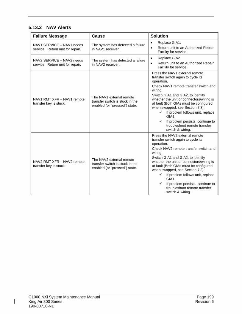
G1000 NXi System Maintenance Manual Page 199 King Air 300 Series Revision 6 190-00716-N1
5.13.2 NAV Alerts Failure Message Cause Solution
NAV1 SERVICE – NAV1 needs service. Return unit for repair.
The system has detected a failure in NAV1 receiver.
• Replace GIA1. • Return unit to an Authorized Repair
Facility for service.
NAV2 SERVICE – NAV2 needs service. Return unit for repair.
The system has detected a failure in NAV2 receiver.
• Replace GIA2. • Return unit to an Authorized Repair
Facility for service.
NAV1 RMT XFR – NAV1 remote transfer key is stuck.
The NAV1 external remote transfer switch is stuck in the enabled (or “pressed”) state.
Press the NAV1 external remote transfer switch again to cycle its operation. Check NAV1 remote transfer switch and wiring. Switch GIA1 and GIA2, to identify whether the unit or connectors/wiring is at fault (Both GIAs must be configured when swapped, see Section 7.3):
If problem follows unit, replace GIA1.
If problem persists, continue to troubleshoot remote transfer switch & wiring.
NAV2 RMT XFR – NAV2 remote transfer key is stuck.
The NAV2 external remote transfer switch is stuck in the enabled (or “pressed”) state.
Press the NAV2 external remote transfer switch again to cycle its operation. Check NAV2 remote transfer switch and wiring. Switch GIA1 and GIA2, to identify whether the unit or connectors/wiring is at fault (Both GIAs must be configured when swapped, see Section 7.3):
If problem follows unit, replace GIA1.
If problem persists, continue to troubleshoot remote transfer switch & wiring.

G1000 NXi System Maintenance Manual Page 200 King Air 300 Series Revision 6 190-00716-N1
5.13.3 Glideslope Alerts Failure Message Cause Solution
G/S1 SERVICE – G/S1 needs service. Return unit for repair.
The system has detected a failure in G/S1 receiver.
• Replace GIA1. • Return unit to an Authorized Repair
Facility for service.
G/S2 SERVICE – G/S2 needs service. Return unit for repair.
The system has detected a failure in G/S2 receiver.
• Replace GIA2. • Return unit to an Authorized Repair
Facility for service.
G/S1 FAIL – G/S1 is inoperative. The system has detected a failure in G/S1 receiver.
• Switch GIA1 and GIA2 to verify location of problem: If problem follows the unit,
replace GIA.
If problem does not follow unit, check G/S1 antenna and cabling.
G/S2 FAIL – G/S2 is inoperative. The system has detected a failure in G/S2 receiver.
• Switch GIA1 and GIA2 to verify location of problem: If problem follows the unit,
replace GIA.
If problem does not follow unit, check G/S2 antenna and cabling.
5.13.4 GPS Alerts NOTE
Before troubleshooting, ensure that no cell phones or devices using cell phone technology are turned on, even in a monitoring state, in the cabin.
Failure Message Cause Solution MANIFEST – GPS1 software mismatch. Communication halted.
The system has detected an incorrect software version loaded in GIA1. Load the correct GPS software. See
Section 7.3 for the Software Loading procedure. MANIFEST – GPS2 software
mismatch. Communication halted.
The system has detected an incorrect software version loaded in GIA2.
GPS1 SERVICE – GPS1 needs service. Return unit for repair.
The system has detected a failure in GPS1 receiver. • Replace GIA unit.
• Return unit to an Authorized Repair Facility for service. GPS2 SERVICE – GPS2 needs
service. Return unit for repair. The system has detected a failure in GPS2 receiver.
GPS1 FAIL – GPS1 is inoperative. The system has detected a failure in GPS1 receiver.
• Switch GIA1 and GIA2, to verify location of problem: If problem follows the unit,
replace GIA. If problem does not follow the
unit, check GPS antenna and cabling.
GPS2 FAIL – GPS2 is inoperative. The system has detected a failure in GPS2 receiver.

G1000 NXi System Maintenance Manual Page 201 King Air 300 Series Revision 6 190-00716-N1
Failure Message Cause Solution
LOI – GPS integrity lost. Crosscheck with other NAVS.
If the primary receiver is a WAAS sensor, the alert indicates that GPS position data has timed out.
• Verify the area the aircraft was traveling through did not have loss of GPS coverage. FAA NOTAMs may be issued for periods of outages, or the US Coast Guard website http://navcen.uscg.gov/pdf/gps/gpsnotices/GPS_Interference.pdf will have notices posted.
• Using the MFD Aux – GPS Status page, verify the signal strength bars are not erratic. If so, this indicates outside interference is affecting the GPS receivers. Find and remove the source of interference (i.e. cell phones, FBO datalink antennas, etc.).
• If GPS receivers cannot acquire a position lock, troubleshoot per the “Will not acquire satellites” section.
GPS NAV LOST – Loss of GPS navigation. Insufficient satellites.
There is no GPS position fix available or the system is in dead reckoning mode.
GPS NAV LOST – Loss of GPS navigation. Position error.
The G1000 has detected an internal position warning has occurred.
GPS NAV LOST – Loss of GPS navigation. GPS fail.
The G1000 has detected a GPS engine failure.
5.13.5 GIA Cooling Alerts Failure Message Cause Solution GIA1 COOLING – GIA1 temperature too low.
GIA1 operating temperature is too low. Allow unit to warm up.
GIA2 COOLING – GIA2 temperature too low.
GIA2 operating temperature is too low. Allow unit to warm up.
GIA1 COOLING – GIA1 over temperature.
GIA1 has exceeded its operating temperature range.
• Check fan, wiring and air tubing for proper operation (if applicable).
• Replace cooling fan if unable to determine if operating correctly.
• Replace GIA1. • If problem persists, contact Garmin
Aviation Product Support for assistance.
GIA2 COOLING – GIA2 over temperature.
GIA2 has exceeded its operating temperature range.
• Check fan, wiring and air tubing for proper operation (if applicable).
• Replace cooling fan if unable to determine if operating correctly.
• Replace GIA2. • If problem persists, contact Garmin
Aviation Product Support for assistance.

G1000 NXi System Maintenance Manual Page 202 King Air 300 Series Revision 6 190-00716-N1
5.13.6 GIA Configuration Alerts Failure Message Cause Solution MANIFEST – GIA1 software mismatch. Communication Halted.
The system has detected an incorrect software version loaded in GIA1. Load the correct software. See Section
7.3 for the Software Loading procedure. MANIFEST – GIA2 software mismatch. Communication Halted.
The system has detected an incorrect software version loaded in GIA2.
GIA1 CONFIG – GIA1 audio config error. Config service req’d.
The GIA’s audio configuration files are incorrect or missing. Reload audio configuration files.
GIA2 CONFIG – GIA2 audio config error. Config service req’d.
GIA1 CONFIG – GIA1 configuration error. Config service req’d.
The system has detected a GIA configuration mismatch. If GIAs are not properly configured after being swapped/replaced, this message appears.
• Load the configuration files for that GIA. See Section 7.3 3.8 for GIA Configuration Loading procedure.
• If problem persists, replace master configuration module, check config module harness for faults and replace if necessary.
NOTE • New Terrain/Obstacle cards,
Jeppesen Aviation Database and other optional features (i.e. TAWS unlock card) will need to be replaced if the master configuration module is changed. The G1000 System ID number will change to a new number when installing a new master config module. The old Terrain and other databases will no longer work as they will remain locked to the old System ID number.
GIA2 CONFIG – GIA2 configuration error. Config service req’d.
GIA1 SERVICE – GIA1 needs service. Return unit for repair. The G1000 has detected a failure
in the specified GIA. • Replace GIA unit. • Return unit to an Authorized Repair
Facility for service. GIA2 SERVICE – GIA2 needs service. Return unit for repair.

G1000 NXi System Maintenance Manual Page 203 King Air 300 Series Revision 6 190-00716-N1
5.14 GEA Troubleshooting 5.14.1 GEA Alerts
Failure Message Cause Solution MANIFEST – GEA1 software mismatch. Communication halted. The system has detected an
incorrect software version loaded in the specified GEA.
Load the correct software version. See Section 7.4 for GEA Software Load Procedure. MANIFEST – GEA2 software
mismatch. Communication halted. GEA1 CONFIG – GEA1 configuration error. Config service req’d.
The system has detected a configuration mismatch in the specified GEA.
• Load GEA configuration files. See Section 7.4 for GEA Configuration Procedure.
• If problem persists, replace master configuration module, check config module harness for faults and replace if necessary.
NOTE New Terrain/Obstacle cards, Jeppesen Aviation Database and other optional features (i.e. TAWS unlock card) will need to be replaced if the master configuration module is changed. The G1000 System ID number will change to a new number when installing a new master config module. The old Terrain and other databases will no longer work as they will remain locked to the old System ID number.
GEA1 CONFIG – GEA2 configuration error. Config service req’d.

G1000 NXi System Maintenance Manual Page 204 King Air 300 Series Revision 6 190-00716-N1
5.15 GTX Troubleshooting 5.15.1 GTX Alerts
Failure Message Cause Solutions MANIFEST – GTX1 software mismatch. Communication halted. The system has detected an
incorrect software version loaded in the specified GTX unit.
Reload software. MANIFEST – GTX2 software mismatch. Communication halted. XPDR1 CONFIG – XPDR1 configuration error. Config service req’d.
The system has detected a configuration mismatch for the specified GTX unit.
• Perform a SET>ACTV configuration reset on the GTX Config page and verify the aircraft registration is present.
• If error is still present, reload config files from a loader card. If problem persists, replace
master configuration module, check config module harness for faults and replace if necessary.
NOTE New Terrain/Obstacle cards, Jeppesen Aviation Database and other optional features (i.e. TAWS unlock card) will need to be replaced if the master configuration module is changed. The G1000 System ID number will change to a new number when installing a new master config module. The old Terrain and other databases will no longer work as they will remain locked to the old System ID number.
XPDR2 CONFIG – XPDR2 configuration error. Config service req’d.
XPDR1 SRVC – XPDR1 needs service. Return unit for repair. The G1000 has detected a failure
in the specified GTX
• Replace GTX unit. • Return unit to an Authorized Repair
Facility for service. XPDR2 SRVC – XPDR2 needs service. Return unit for repair. XPDR1 FAIL – XPDR 1 is inoperative.
The specified GTX is not responding.
• Check wiring between GIA’s and GTX.
• Replace GTX unit. • Return unit to an Authorized Repair
Facility for service.
XPDR2 FAIL – XPDR 2 is inoperative.
XPDR 1 ADS-B NO POS – Transponder ADS-B is not transmitting - OR - XPDR 1 ADS-B NO TX – Transponder ADS-B out failed The specified GTX transponder is
not able to transmit ADS-B data.
• Wait for GPS receivers to obtain a position lock.
• Check wiring between GIA’s and GPS antenna.
• Check wiring between GIA’s and GTX.
XPDR 2 ADS-B NO POS – Transponder ADS-B is not transmitting - OR - XPDR 2 ADS-B NO TX – Transponder ADS-B out failed.

G1000 NXi System Maintenance Manual Page 205 King Air 300 Series Revision 6 190-00716-N1
5.16 GDL 69A or GDL69A SXM Troubleshooting 5.16.1 GDL 69A or GDL69A SXM Symptoms
Symptom Recommended Action No SiriusXM audio is heard • Ensure the following items are not preventing the audio panel from
distributing SiriusXM audio (reference applicable G1000 Pilot’s Guide): Verify the SiriusXM volume is not muted on the Aux – XM Radio
page on the MFD. Verify the COM squelch is not open. Verify the ICS squelch is not open. Verify the marker beacon tones are not being received. Verify the headphone (if equipped) volume is turned up.
• Go to the Aux – System Status page on the MFD and ensure unit is online. If a red X is present, verify the unit is receiving power at the rack
connector. • Ensure there are no GDL alerts in the alert window. If there is an Alert
for software or configuration error or mismatch, reload the file noted in the Alert.
• Restart the PFD’s and MFD in configuration mode and go to the GDL page. Verify unit is active. Verify the Signal number is “2” or “3”. If it is “0” or “1” check the
GDL 69A/69A SXM antenna and cabling for faults. Reseat the 69A/69A SXM to verify the coax connector is fully
seated. If unit is not active, contact SiriusXM Customer service to have a
refresh signal sent to your unit. You will need to provide them the Audio Radio ID (and Data Radio ID number for SiriusXM weather) numbers. Also verify with SiriusXM that the correct Weather package (Aviator Lite or Aviator) is on the account, and that no traffic service has been activated against that Radio ID. The unit must be on for approximately one hour after the request for the refresh has been sent to receive the signal. Alternatively, go to SiriusXM’s website and enter the radio ID’s
to have a refresh signal sent. If there are still problems receiving weather products after
performing the above step, call SiriusXM and have the account deactivated, and a new account activated to clear out any corrupt account information.
Verify there is a good ground connection through the aircraft between the MFD and the GDL69/69A unit. Reference the Aircraft Maintenance Manual for instructions on how to check bonding and ground points.
If problem persists, replace the GDL 69A/69A SXM. Return unit to an Authorized Repair Facility for service.
No SiriusXM weather information is displayed

G1000 NXi System Maintenance Manual Page 206 King Air 300 Series Revision 6 190-00716-N1
5.16.2 GDL 69A Alerts Failure Message Cause Solutions
GDL 69 FAIL – GDL 69 has failed. The G1000 has detected a failure in the GDL 69A/69A SXM.
• Replace GDL 69A/69A SXM. • Check GDL 69A/69A SXM antenna
and cabling.
• Check the GDL 69A/69A SXM and MFD interconnect.
GDL69 CONFIG – GDL 69 configuration error. Config service req’d.
The G1000 has detected a GDL 69A/69A SXM configuration mismatch.
• Reload configuration file. See Section 3.8 for the Configuration Procedure.
• If problem persists, replace master configuration module, check config module harness for faults and replace if necessary.
NOTE New Terrain/Obstacle cards, Jeppesen Aviation Database and other optional features (i.e. TAWS unlock card) will need to be replaced if the master configuration module is changed. The G1000 System ID number will change to a new number when installing a new master config module. The old Terrain and other databases will no longer work as they will remain locked to the old System ID number.
MANIFEST – GDL software mismatch. Communication halted.
The system has detected an incorrect software version loaded in the GDL 69A/69A SXM.
Load correct software version.

G1000 NXi System Maintenance Manual Page 207 King Air 300 Series Revision 6 190-00716-N1
5.17 GSU 75B, GRS 77, or GRS 7800 and GMU 44 Troubleshooting 5.17.1 AHRS Symptoms
Symptom Recommended Action
AHRS/ADAHRS does not complete initialization
• Ensure that a cell phone or a device using cell phone technology is not turned on (even in a monitoring state) in the cabin.
• Ensure GPS has acquired at least four satellites, has a 3D navigation solution, and a DOP of less than 5.0. This is particularly important if this issue appears during ground operation only.
• Calibrate the GSU75B, GRS 77, or GRS 7800. • Check GSU75B, GRS 77, or GRS 7800 configuration module wiring for
damage. • Check GSU75B, GRS 77, or GRS 7800 connector for bent pins.
If no damage can be found, replace GSU75B, GRS 77, or GRS 7800 configuration module.
If problem persists, replace the GSU75B, GRS 77, or GRS 7800.
Attitude appears unstable
• Ensure that a cell phone or a device using cell phone technology is not turned on (even in a monitoring state) in the cabin. (Wi-Fi and Bluetooth may be operational) GRS 77 • Ensure the four mounting screws are tight. Finger tight is not sufficient, a
screwdriver must be used to verify. GRS 7800 • Ensure the hold down clamps are tight. GSU 75B • Ensure the two mounting jack screws are tight.
• Ensure mounting rack and airframe shelf are secure and all hardware and brackets are present (CAUTION - do not loosen the mounting rack hardware to the airframe shelf or the aircraft will need to be re-leveled and the PITCH/ROLL OFFSET procedure performed).
• Ensure the GSU 75B, GRS 77, or GRS 7800 connector is securely fastened and proper strain relief is provided.
• Remove the GSU 75B, GRS 77, or GRS 7800 connector and verify there are no bent pins.
• Replace the GSU 75B, GRS 77, or GRS 7800. • Contact Garmin for further troubleshooting if required.

G1000 NXi System Maintenance Manual Page 208 King Air 300 Series Revision 6 190-00716-N1
5.17.2 GRS/GSU Alerts Failure Message Cause Solutions MANIFEST – GRS1 software mismatch. Communication halted. The system has detected an
incorrect software version loaded in the specified GRS unit.
Load correct software version. MANIFEST – GRS2 software mismatch. Communication halted. AHRS1 SERVICE – AHRS1 magnetic-field model needs update.
The AHRS magnetic field model should be updated for the specified unit. Appears on ground only.
Load updated AHRS magnetic field file. See Section 4.6. AHRS2 SERVICE – AHRS2
magnetic-field model needs update. GEO LIMITS – AHRS1 too far north/south, no magnetic compass. No magnetic compass information
available due to being too far north or south.
Operate the aircraft only within the limits as specified in the G1000 King Air 300 AFMS. GEO LIMITS – AHRS2 too far
north/south, no magnetic compass. AHRS1 TAS – AHRS1 not receiving airspeed.
The specified GSU 75B, GRS 77, or GRS 7800 is not receiving airspeed from the air data card, or GDC 7400.
• Check GRS/GDC interconnect for faults. (Internal fault between the ADC and AHRS cards in the GSU 75B)
• Replace the GSU 75B or GDC 7400 • If problem persists, replace the GSU
75B, GRS 77, or GRS 7800.
AHRS2 TAS – AHRS2 not receiving airspeed.
AHRS1 GPS – AHRS1 not receiving backup GPS information.
The GSU 75B, GRS 77, or GRS 7800 #1 is not receiving backup GPS information from either GIA 63.
• Ensure that a cell phone or a device using cell phone technology is not turned on (even in a monitoring state) in the cabin.
• Check GPS status for GIA 1 and 2 on MFD Aux – GPS Status page. If one or both GPS receivers cannot acquire a position lock, see GPS troubleshooting section
• Troubleshoot GIA1/2 –GRS1 wiring for faults (ref. Failed Path troubleshooting section).
• Replace the GRS or GSU #1.
AHRS1 GPS – AHRS1 operating exclusively in no-GPS mode.
The GSU 75B, GRS 77, or GRS 7800 #1 is operating in the absence of GPS.
AHRS1 GPS – AHRS1 not receiving any GPS information.
The GSU 75B, GRS 77, or GRS 7800 #1 is not receiving GPS data from the GPS receivers.
AHRS1 GPS – AHRS1 using backup GPS source.
The GSU 75B, GRS 77, or GRS 7800 #1 is using the backup GPS data path.
AHRS2 GPS – AHRS2 not receiving backup GPS information.
The GSU 75B, GRS 77, or GRS 7800 #2 is not receiving backup GPS information from either GIA 63.
• Ensure that a cell phone or a device using cell phone technology is not turned on (even in a monitoring state) in the cabin.
• Check GPS status for GIA 1 and 2 on MFD - Aux – GPS Status page. If one or both GPS receivers cannot acquire a position lock, see GPS troubleshooting section
• Troubleshoot GIA1/2 – GSU/GRS2 wiring for faults (ref. Failed Path troubleshooting section).
• Replace the GRS or GSU #2.
AHRS2 GPS – AHRS2 operating exclusively in no-GPS mode.
The GSU 75B, GRS 77, or GRS 7800 #2 is operating in the absence of GPS.
AHRS2 GPS – AHRS2 not receiving any GPS information.
The GSU 75B, GRS 77, or GRS 7800 #2 is not receiving GPS data from the GPS receivers.
AHRS2 GPS – AHRS2 using backup GPS source.
The GSU 75B, GRS 77, or GRS 7800 #2 is using the backup GPS data path.
AHRS MAG DB – AHRS magnetic model database version mismatch.
The G1000 has detected a magnetic model database version mismatch.
Load AHRS magnetic model field in both GSU/GRS units.

G1000 NXi System Maintenance Manual Page 209 King Air 300 Series Revision 6 190-00716-N1
Failure Message Cause Solutions
MAG VAR WARN – Large magnetic variance. Verify all course angles.
Magnetic variance value from GMU 44 is not accurate.
• If flying near large radio towers or other sources of possible electromagnetic interference, the condition should correct itself as the aircraft leaves the area.
• If problem persists, run magnetic interference check in Section 5.17.4 to check for magnetic interference in the aircraft.
PIT (amber pitch flag) Pitch Miscompare: Difference in the pitch sensors is greater than 5 degrees.
Perform Calibration Procedure A1: GSU 75B, GRS 77, or GRS 7800 Pitch/Roll Offset Calibration (reference Section 7.10.1).
ROL (amber roll flag) Roll Miscompare: Difference in the roll sensors is greater than 6 degrees.
Perform Calibration Procedure A1: GSU 75B, GRS 77, or GRS 7800 Pitch/Roll Offset Calibration (reference Section 7.10.1).
5.17.3 GMU Alerts Failure Message Cause Solutions MANIFEST – GMU1 software mismatch. Communication halted. The system has detected an
incorrect software version loaded in the specified GMU 44.
Load the correct software version. MANIFEST – GMU2 software mismatch. Communication halted. HDG FAULT – AHRS1 magnetometer fault has occurred
A fault has occurred in the specified magnetometer; heading will be flagged invalid.
• Check GMU 44/GSU 75B, GRS 77, or GRS 7800 interconnect for faults. Replace GMU 44. If problem persists, replace
GSU 75B, GRS 77 or GRS 7800.
HDG FAULT – AHRS2 magnetometer fault has occurred.
HDG (amber heading flag) Heading Miscompare: Difference in the heading sensors is greater than 6 degrees.
Perform Calibration Procedure E: Magnetometer Interference Test (reference Section 5.17.4) and Procedure B: GSU 75B, GRS 77, or GRS 7800 and GMU 44 Magnetometer Calibration (reference Section 7.10.3).

G1000 NXi System Maintenance Manual Page 210 King Air 300 Series Revision 6 190-00716-N1
5.17.4 Calibration Procedure E: Magnetometer Interference Test A magnetometer interference test is available for troubleshooting and/or verifying a magnetically ‘clean’ installation of the GMU 44. This test exercises various devices on the aircraft that could potentially affect the magnetic field as measured by the GMU 44.
NOTE This test is used to validate that no electronic device or magnetized components produce a magnetic field sufficient to interfere with the operation of the GMU 44 magnetometer. It is highly recommended that this test be performed after installation or maintenance of electrical components on the aircraft and/or for troubleshooting the GMU 44.
Figure 5-7, Magnetometer Interference Test
1. Initiate the AHRS magnetometer interference test procedure by performing the following steps:
2. On PFD1, enter Configuration Mode and go to GRS/GMU Calibration page as shown in Figure 5-7.
3. This page is protected and requires a keystroke password to perform this test. Press the following softkeys in sequence: (as counted from left to right on lower bezel of MFD)
• softkey 9
• softkey 10
• softkey 11
• softkey 12 4. Select MAG INTERFERENCE TEST and press the PFD1 ENT key. 5. Follow the checklist items displayed on the PFD1, and press the ENT key as each one is
completed or confirmed.

G1000 NXi System Maintenance Manual Page 211 King Air 300 Series Revision 6 190-00716-N1
NOTE The 3rd item on the checklist instructs the operator to “prepare a detailed test sequence with precise start and stop times for exercising all electronic devices”. The list of relevant electronic devices are given in Table 5-5. Begin test with flaps retracted, flight controls in a neutral position, all lights selected OFF.
Table 5-5, Magnetometer Interference Test Sequence
Elapsed Time since Start of Test (min:secs) Action
0:00 Test begins 0:05 Tail Flood lights on 0:10 Tail Flood lights off 0:20 Navigation lights on 0:30 Navigation lights off 0:40 Landing lights on 0:50 Landing lights off 1:00 Taxi lights on 1:20 Taxi lights off 1:40 Strobes on 1:50 Strobes off 2:00 Recognition lights on 2:10 Recognition lights off 2:20 Beacon on 2:30 Beacon off 2:40 Rudder full left 2:50 Rudder full right 3:00 Rudder Trim full left 3:10 Rudder Trim full right 3:20 Elevator full nose UP 3:30 Elevator full nose DN
3:40 Elevator trim full nose UP (manual electric)
3:50 Elevator trim full nose DN (manual electric)
4:00 End of test

G1000 NXi System Maintenance Manual Page 212 King Air 300 Series Revision 6 190-00716-N1
6. When the CALIBRATE field is blinking, press the ENT key to begin the procedure, and have a stopwatch ready to begin recording the elapsed time.
NOTE It is important that the “time equals zero” moment corresponds with the moment the PFD first displays the blinking TEST COMPLETE? Message.
7. The operator should carry out the actions called for in the prepared test sequence.
NOTE
It is important that all actions are carried out in the order and at the precise elapsed time as specified in the prepared test sequence.
8. When the operator has completed the actions specified in the test sequence, press the ENTER button to indicate that the process is complete. When this is done, the TEST COMPLETE field stops blinking.
9. PFD1 informs the operator if the installation has passed or failed the magnetometer interference test. If the test passes, no further action is required for this test. If the test fails, the installation should be considered unreliable until the source of magnetic interference is identified and remedied. When the magnetometer interference test fails, record the three magnetometer maximum deviation values and their corresponding timestamps. Reference the appropriate installation manual for the GSU 75B (190-01639-00), GRS 77 (190-00303-10), and GRS 7800 (190-01091-00) for acceptable magnetic interference limits. Compare the corresponding timestamps with the prepared test sequence to identify which action produced the problem. Contact Garmin for assistance in resolving the problem.
NOTE Three common reasons for a failed magnetometer interference test are: 1) rudder bellcrank or other structure has become magnetized, 2) new equipment is installed in close proximity to the GMU 44 magnetometer, and 3) an existing or new electronic device has become grounded through the aircraft structure instead of via the proper ground wire in a twisted shielded pair.
10. Press the ENT key on the PFD to conclude this procedure.
5.18 GSU 75B/GDC 7400 Troubleshooting 5.18.1 Air Data Symptoms
Symptom Recommended Action
Altitude shown on PFD is different than standby altimeter
• Perform a pitot/static leak and accuracy check. • Determine which instrument is outside limits and replace.
Note: The GSU 75B and GDC 7400 software/configuration for the 300
Series contains error correction at 19,000 feet and above. The standby altimeter does not contain any correction.
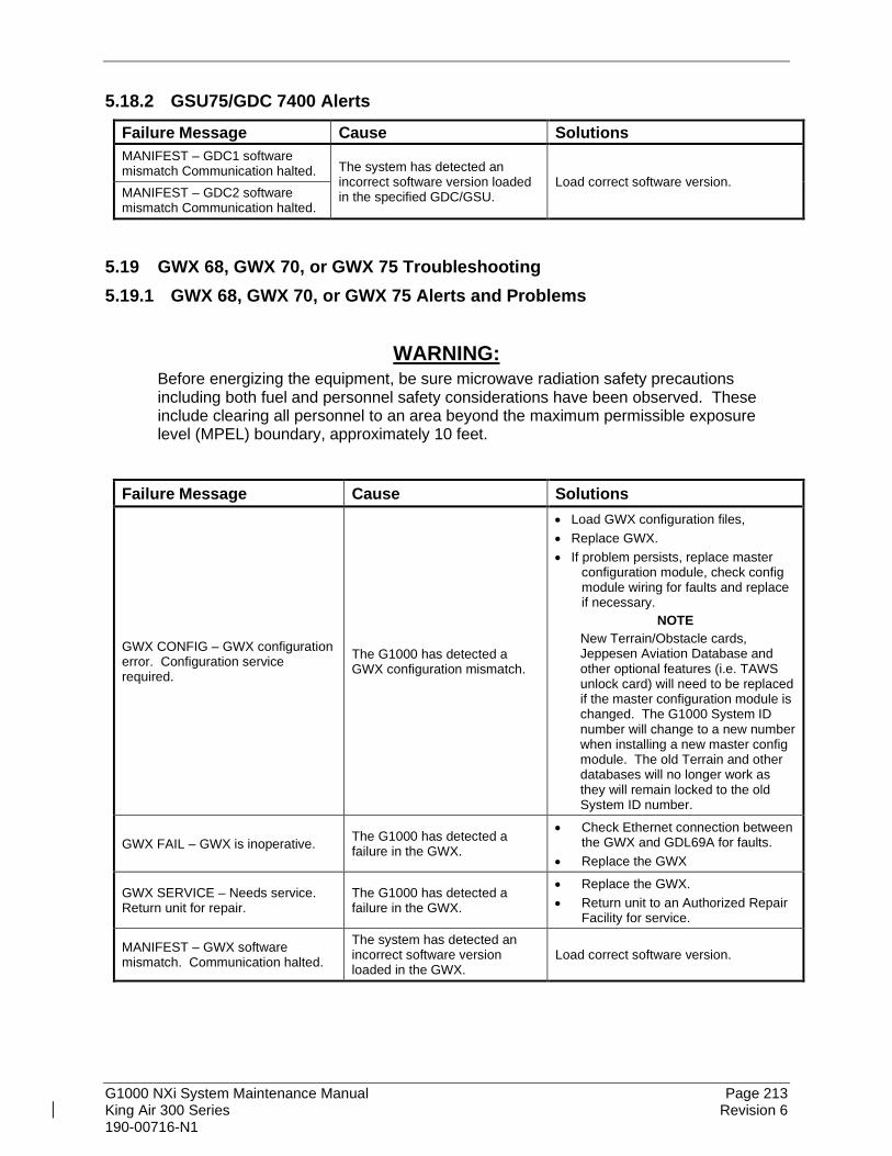
G1000 NXi System Maintenance Manual Page 213 King Air 300 Series Revision 6 190-00716-N1
5.18.2 GSU75/GDC 7400 Alerts Failure Message Cause Solutions MANIFEST – GDC1 software mismatch Communication halted. The system has detected an
incorrect software version loaded in the specified GDC/GSU.
Load correct software version. MANIFEST – GDC2 software mismatch Communication halted.
5.19 GWX 68, GWX 70, or GWX 75 Troubleshooting 5.19.1 GWX 68, GWX 70, or GWX 75 Alerts and Problems
WARNING: Before energizing the equipment, be sure microwave radiation safety precautions including both fuel and personnel safety considerations have been observed. These include clearing all personnel to an area beyond the maximum permissible exposure level (MPEL) boundary, approximately 10 feet.
Failure Message Cause Solutions
GWX CONFIG – GWX configuration error. Configuration service required.
The G1000 has detected a GWX configuration mismatch.
• Load GWX configuration files, • Replace GWX. • If problem persists, replace master
configuration module, check config module wiring for faults and replace if necessary.
NOTE New Terrain/Obstacle cards, Jeppesen Aviation Database and other optional features (i.e. TAWS unlock card) will need to be replaced if the master configuration module is changed. The G1000 System ID number will change to a new number when installing a new master config module. The old Terrain and other databases will no longer work as they will remain locked to the old System ID number.
GWX FAIL – GWX is inoperative. The G1000 has detected a failure in the GWX.
• Check Ethernet connection between the GWX and GDL69A for faults.
• Replace the GWX
GWX SERVICE – Needs service. Return unit for repair.
The G1000 has detected a failure in the GWX.
• Replace the GWX. • Return unit to an Authorized Repair
Facility for service.
MANIFEST – GWX software mismatch. Communication halted.
The system has detected an incorrect software version loaded in the GWX.
Load correct software version.

G1000 NXi System Maintenance Manual Page 214 King Air 300 Series Revision 6 190-00716-N1
5.20 GMC 710 Troubleshooting 5.20.1 GMC 710 Alerts and Problems
Failure Message Cause Solutions
GMC CNFG – GMC Config error. Config service req’d.
The G1000 has detected a GMC 710 configuration mismatch.
• Load GMC configuration files. • Replace GMC. • If problem persists, replace master
configuration module, check config module wiring for faults and replace if necessary.
NOTE New Terrain/Obstacle cards, Jeppesen Aviation Database and other optional features (i.e. TAWS unlock card) will need to be replaced if the master configuration module is changed. The G1000 System ID number will change to a new number when installing a new master config module. The old Terrain and other databases will no longer work as they will remain locked to the old System ID number.
GMC FAIL – GMC is inoperative. The G1000 has detected a failure in the GMC 710.
• Check wiring for faults (ref Failed Path troubleshooting Sections 5.1.1 and 5.9).
• Replace the GMC 710. • Return unit to an Authorized Repair
Facility for service.
MANIFEST – GMC software mismatch. Communication halted.
The system has detected an incorrect software version loaded in the GMC 710.
Load the correct software version.
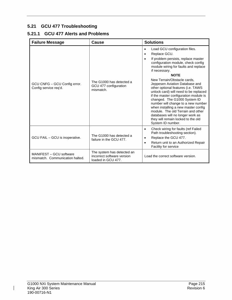
G1000 NXi System Maintenance Manual Page 215 King Air 300 Series Revision 6 190-00716-N1
5.21 GCU 477 Troubleshooting 5.21.1 GCU 477 Alerts and Problems
Failure Message Cause Solutions
GCU CNFG – GCU Config error. Config service req’d.
The G1000 has detected a GCU 477 configuration mismatch.
• Load GCU configuration files. • Replace GCU. • If problem persists, replace master
configuration module, check config module wiring for faults and replace if necessary.
NOTE New Terrain/Obstacle cards, Jeppesen Aviation Database and other optional features (i.e. TAWS unlock card) will need to be replaced if the master configuration module is changed. The G1000 System ID number will change to a new number when installing a new master config module. The old Terrain and other databases will no longer work as they will remain locked to the old System ID number.
GCU FAIL – GCU is inoperative. The G1000 has detected a failure in the GCU 477.
• Check wiring for faults (ref Failed Path troubleshooting section).
• Replace the GCU 477. • Return unit to an Authorized Repair
Facility for service
MANIFEST – GCU software mismatch. Communication halted.
The system has detected an incorrect software version loaded in GCU 477.
Load the correct software version.

G1000 NXi System Maintenance Manual Page 216 King Air 300 Series Revision 6 190-00716-N1
5.22 Software/Configuration Troubleshooting
Problem Solutions MFD or PFD displays do not power up: • Ensure that the criteria listed in Section 5.22.1 are
fulfilled for the applicable situation. • Ensure power is present at display backshell
connector. • Troubleshoot per the “Blank Display” GDU section.
Software file load fails:
• Ensure that criteria listed in Section 5.22.1 are fulfilled for the applicable situation.
• Ensure that LRU is reporting data on Aux – System Status page (LRU is ‘ONLINE’). Check data path wiring as needed.
• Retry software file load or try using a different card. Ensure that the MFD is not touched during the loading process.
• Ensure that LRU part number is compatible with software version and Card Loader. Refer to Section 3.2.3.
• Replace LRU.
Configuration file load fails:
• Ensure that the criteria listed in Section 5.22.1 are fulfilled for the applicable situation.
• Ensure that LRU is reporting data on the Aux – System Status page (LRU is ‘ONLINE’). Check data path wiring as needed.
• Retry configuration file load or try using a different card. Ensure that the MFD is not touched during the loading process.
• Ensure that LRU part number is compatible with Card Loader. Refer to Section 3.2.3.
• Replace LRU.
GIA1 and/or GIA2 to ‘LRU’ data path not working • Ensure that the criteria listed in Section 5.22.1 are fulfilled for the applicable situation.
• Ensure GIA1 and GIA2 are configured correctly. • Check wiring, connectors & pins as needed.
Software File Mismatch Alert appears in lower right corner of PFD when started in normal mode:
• Ensure that proper software file part number and version were loaded to LRU. Refer to Section 5.22.1.
• Check and ensure that correct Card Loader was used during load process. Refer to the General Arrangement Drawing.
• Reload software to LRU.
After being in configuration mode, the PFD displays a red AFCS annunciation and cycling of the transponder field between valid and invalid states.
With the G1000 system powered on, open the MFD, PFD 1 (PRI), PFD 1 (SEC), and PFD 2 circuit breakers for approximately 30 seconds, then close the circuit breakers.

G1000 NXi System Maintenance Manual Page 217 King Air 300 Series Revision 6 190-00716-N1
5.22.1 System Communication Hierarchy The following criteria must be satisfied to be able to perform the desired operation:
Desired Operation Criteria for Success Load Software to MFD or PFD Displays • SW Loader Card must be inserted in top slot for
each display to be loaded. • CLR & ENT keys must be held during power up of
display. • Power on only one display at a time during
software loading.
Load AIRFRAME, SYSTEM, MFD1, PFD 1, PFD 2 and MANIFEST configuration files to MFD and PFDs
• SW Loader Card must be inserted in top slot of PFD 1.
• PFD 1 and MFD must be powered on. • PFD 1 and MFD must have correct software.
Load Software/Configuration files to GIA 63Ws or GIA 64Es
• SW Loader Card must be inserted in top slot of PFD 1.
• G1000 system must be powered on. • PFD and MFD must have correct software. • PFD 1 and MFD must be successfully configured
with AIRFRAME, SYSTEM, MANIFEST, MFD1, PFD 1 and PFD 2 configuration files.
Load Software/Configuration files to: - GMA 1347D or GMA 1360D - GSU 75B - GDC 7400 - GEA 71 or GEA 71B - GRS 77 or GRS 7800 (software only) - GMU 44 (software only) - GTX 33, or GTX 3000 - GTX 335R and/or GTX 345R
• SW Loader Card must be inserted into PFD 1 top slot.
• G1000 must be powered on. • PFD 1 and MFD must have correct software and
configuration settings. • GIA must have correct software. • GIA must be successfully configured with GIA1
and GIA2 configuration files. • Data path from GIA1 to each LRU must be
operational.

G1000 NXi System Maintenance Manual Page 218 King Air 300 Series Revision 6 190-00716-N1
5.23 Backshell/Backplate Connectors The following figures depict the backplate connectors as viewed with the LRU removed.
Figure 5-8, GIA 63W/64E Backplate Connectors
1 2 316 17
4 5 6 7 8 9 10 11121314151819 20 21222324 2526 2728 2930
31323334 353637 38394041 424344
1 2 3 4 5 6 7 8 9 10 11 12 13 14 15 16 17 18 19 2021 22 23 24 25 26 27 28 29 30 31 32 33 34 35 36 37 38 39
40 41 42 43 44 45 46 47 48 49 50 51 52 53 54 55 56 57 58 5960 61 62 63 64 65 66 67 68 69 70 71 72 73 74 75 76 77 78
1 2 3 4 5 6 7 8 9 10 11 12 13 14 15 16 17 18 19 2021 22 23 24 25 26 27 28 29 30 31 32 33 34 35 36 37 38 39
40 41 42 43 44 45 46 47 48 49 50 51 52 53 54 55 56 57 58 5960 61 62 63 64 65 66 67 68 69 70 71 72 73 74 75 76 77 78
COM BOARD CONNECTOR (P601)COM ANTENNA CONNECTOR
COOLING PORT
MAIN DISCRETE CONNECTOR (P604)
MAIN SERIAL CONNECTOR (P603)
GPS ANTENNA CONNECTO
I/O CONNECTOR #2 (P606) I/O CONNECTOR #1 (P605)
G/S ANTENNA CONNECTOR
NAV ANTENNA CONNECTORVOR/ILS CONNECTOR (P60

G1000 NXi System Maintenance Manual Page 219 King Air 300 Series Revision 6 190-00716-N1
Figure 5-9, GEA 71/71B Backplate Connectors
Figure 5-10, GMA 1347D/1360D Backplate Connectors
Figure 5-11, GTX 33/33D Backplate Connectors
1 2 3 4 5 6 7 8 9 10 11 12 13 14 15 16 17 18 19 20 21 22 23 24 25 26 27 28 29 30 31 32 33 34 35 36 37 38 39
40 41 42 43 44 45 46 47 48 49 50 51 52 53 54 55 56 57 58 59 60 61 62 63 64 65 66 67 68 69 70 71 72 73 74 75 76 77 78
P13471 P13472
1 2 3 4 5 6 7 8 9 10 11 12 13 14 15 16 17 18 19 20 21 22 23 24 25 26 27 28 29 30 31 32 33 34 35 36 37 38 39 40 41 42
43 44 45 46 47 48 49 50 51 52 53 54 55 56 57 58 59 60 61 62
TOP ANTENNA CONNECTOR BOTTOM ANTENNA CONNECTOR
P331 COOLING PORT
1 2 3 4 5 6 7 8 9 10 11 12 13 14 15 16 17 18 19 20
21 22 23 24 25 26 27 28 29 30 31 32 33 34 35 36 37 38
40 41 42 43 44 45 46 47 48 49 50 51 52 53 54 55 56 57 58 59
60 61 62 63 64 65 66 67 68 69 70 71 72 73 74 75 76 77 78
P712 P711

G1000 NXi System Maintenance Manual Page 220 King Air 300 Series Revision 6 190-00716-N1
(P3301)
Figure 5-12, GTX 3000 Connectors (P3301 and P3302)
Figure 5-13, GTX 335R/345R Looking at Front of Connector (P3251)

G1000 NXi System Maintenance Manual Page 221 King Air 300 Series Revision 6 190-00716-N1
Figure 5-14, GTX 345R (Only) Looking at Front of Connector (P3252)
Figure 5-15, GDU 1050A/1550 Backshell Connector (P10401 or P15001)
Figure 5-16, GRS 77 Backshell Connector (P771)

G1000 NXi System Maintenance Manual Page 222 King Air 300 Series Revision 6 190-00716-N1
Figure 5-17, GRS 7800 Backshell Connector (P78001)
Figure 5-18, GSU 75B Connector View from Front (P751)
Figure 5-19, GDC 7400 Mating Connector (P74001)
Figure 5-20, GDL 69A/GDL 69A SXM Backplate Connector (P69A1)

G1000 NXi System Maintenance Manual Page 223 King Air 300 Series Revision 6 190-00716-N1
Figure 5-21, GCU 477 Backshell Connector (P4751)
Figure 5-22, GMC 710 Backshell Connector (P7101)
Figure 5-23, GWX 68 Backshell Connector (P681)
Figure 5-24, GWX 70/75 Backshell Connector (P751)
Figure 5-25, GTS 820/850 Mating Connectors (P8001 and P8002)
(Rear View)

G1000 NXi System Maintenance Manual Page 224 King Air 300 Series Revision 6 190-00716-N1
Figure 5-26, GTS 820/850 Mating Connector (P8003) (Rear View)
Figure 5-27, GTS Processor Connector (P8001)
Figure 5-28, GPA 65 Mating Connector (P651) (Rear View)
Figure 5-29, Signal Conditioner (1PVIB1 and 2PVIB1)
(Rear View)

G1000 NXi System Maintenance Manual Page 225 King Air 300 Series Revision 6 190-00716-N1
Figure 5-30, GDL 59 Mating Connector (1P591) (Rear View)
Figure 5-31, GSR 56 Mating Connector (1P561) (Rear View)
Figure 5-32, GRA 5500 Connector (P55001)
Figure 5-33, GSD 41 Backplate Connector (P411)
(Rear View)
Figure 5-34, GSA 9000 Mating Connector (P90001)
(Rear View)
1 2 3 4 5 6 7 8 9 10 11 12 13 14 15 16 17 18 19 20
21 22 23 24 25 26 27 28 29 30 31 32 33 34 35 36 37 38 39
40 41 42 43 44 45 46 47 48 49 50 51 52 53 54 55 56 57 58 59
60 61 62 63 64 65 66 67 68 69 70 71 72 73 74 75 76 77 78
123456789101112131415
161718192021222324252627282930
3132333435363738394041424344
1 2 3 4 5 6 7 8 9 10 11 12 13 14 15 16 17 18 19 20
21 22 23 24 25 26 27 28 29 30 31 32 33 34 35 36 37 38 39
40 41 42 43 44 45 46 47 48 49 50 51 52 53 54 55 56 57 58 59
60 61 62 63 64 65 66 67 68 69 70 71 72 73 74 75 76 77 78

G1000 NXi System Maintenance Manual Page 226 King Air 300 Series Revision 6 190-00716-N1
5.24 Mechanical Standby Attitude Indicator Troubleshooting
Symptom Recommended Action
Warning flag pops into view, indicating that the gyro motor is not receiving sufficient power to operate
• Perform the Standby Instrument Electrical Power Checks in Section 9.9. • Remove the unit per Section 6.28.3 and inspect the electrical connector. • Check to ensure appropriate electrical power is being supplied to the
instrument. • If input electrical power is not adequate, troubleshoot the wiring
harness. • If input power is appropriate, the unit must be removed and serviced
by a qualified service facility. Contact the manufacturer to find a qualified service facility
Unit fails to perform to specifications
The unit must be removed and serviced by a qualified service facility. See Section 6.28.3 for removal instructions. Contact the manufacturer to find a qualified service facility.
5.25 Mechanical Standby Airspeed Indicator Troubleshooting
Symptom Recommended Action
Airspeed Indicator lighting is inoperative or malfunctioning
• Perform the Standby Instrument Electrical Power Checks in Section 9.9. • Remove standby airspeed indicator per Section 6.28.1 and inspect the
electrical connector. • Check that electrical power is being appropriately supplied to the
instrument. • If the input electrical power is not adequate, troubleshoot the wiring
harness. • If the input electrical power is appropriate, replace the standby
airspeed indicator or contact the manufacturer for further troubleshooting.
Airspeed displayed is incorrect
• Using a pitot-static ramp tester, check airspeed displayed on standby altimeter against airspeed display from ADC2. • If the airspeeds are the same, inspect the pitot/static ports and
associated equipment for faults. • If the airspeeds are different, replace the standby altimeter or contact
the manufacturer for further troubleshooting. See Section 6.28.1 for removal instructions.

G1000 NXi System Maintenance Manual Page 227 King Air 300 Series Revision 6 190-00716-N1
5.26 Mechanical Standby Altimeter Troubleshooting
Symptom Recommended Action
Altimeter lighting is inoperative or malfunctioning
• Perform the Standby Instrument Electrical Power Checks in Section 9.9. • Remove standby altimeter per Section 6.28.2 and inspect the electrical
connector. • Check that electrical power is being appropriately supplied to the
instrument. • If the input electrical power is not adequate, troubleshoot the wiring
harness. • If the input electrical power is appropriate, replace the standby
altimeter or contact the manufacturer for further troubleshooting.
Altimeter Vibrator is inoperative or malfunctioning or fail flag is displayed
Altitude displayed is incorrect
• Using a pitot-static ramp tester, check altitude displayed on standby altimeter (Note that PFD2 has error correction above 19,000 ft. and will not be the same as the non-corrected standby altimeter.)
• Inspect the pitot/static ports and associated equipment for faults. • Replace the standby altimeter or contact the manufacturer for further
troubleshooting. See Section 6.28.2 for removal instructions.
5.27 MD 302 Standby Indicator Troubleshooting
Symptom Recommended Action
Standby indicator is inoperative
• Perform the Standby Instrument Electrical Power Checks in Section 9.9. • Remove standby indicator per Section 6.27.1 and inspect the electrical
connector. • Check that electrical power is being appropriately supplied to the
instrument. • If the input electrical power is not adequate, troubleshoot the wiring
harness. • If the input electrical power is appropriate, replace the standby
altimeter or contact the manufacturer for further troubleshooting.
Displayed altitude or airspeed appears incorrect
• Using a pitot-static ramp tester, check altitude displayed on standby altimeter for accuracy.
• Perform airspeed and altitude calibration per Section 3.19.2 • Inspect the pitot/static ports and associated equipment for faults. • Replace the standby altimeter or contact the manufacturer for further
troubleshooting. See Section 6.27.1 for removal instructions.
Red X’s on display. Troubleshoot per Mid-Continent Instruments and Avionics MD 302 Installation Manual number 9017782 available at www.flysam.com/specifications/ or call US 316-630-0101. Warning or Error Messages

G1000 NXi System Maintenance Manual Page 228 King Air 300 Series Revision 6 190-00716-N1
5.28 GDL 59 Troubleshooting
Symptom Recommended Action
No communication with GDL 59 • Check power wiring and pin out of GDL 59 unit. • Ensure GDL 59 configuration option has been loaded.
No or low-quality Wi-Fi signal
• Verify that a Wi-Fi network is configured and available. • Ensure the Wi-Fi antenna is within range of a Wi-Fi network. • Remove any obstacles between the aircraft Wi-Fi antenna and the Wi-Fi
network hub that may be blocking the signal. • Check the Wi-Fi antenna cable and connectors. • Verify antenna ground plane is adequate.
Connects to Wi-Fi but cannot send report data
Activate Garmin Connext (reference Section 8.16). Note that a replacement GDL 59 unit must be registered again, even if the MFD already shows REGISTERED.
5.29 GSR 56 Troubleshooting
Symptom Recommended Action
No communication with GSR 56 • Check power wiring and pin out of GSR 56 unit. • Ensure GSR 56 configuration option has been loaded.
No or low-quality Iridium signal
• Ensure the Iridium antenna has an unobstructed view of satellite constellation.
• Check the Iridium antenna cable and connectors. • Verify antenna ground plane is adequate.
No audio output • Check wiring from GSR 56 to GDL 59 or from GSR 56 to GIA #1 (stand-
alone), as applicable to the installation. • Verify subscription with Garmin Connext (reference Section 8.16).
Unable to make a phone call • Verify signal quality is adequate • Verify communication between GSR 56 and the display/control device • Verify subscription with Garmin Connext (reference Section 8.16).
5.30 GTS 820/850 Troubleshooting
Problem Cause Solution
Unit does not power up – Data failed message
Improper wiring; circuit breaker open Ensure power is properly wired to the GTS 820/850 and the TRFC circuit breaker is closed.
Improper configuration Verify that the GTS 820/850 is configured correctly for the desired display.
Traffic Display erroneously indicates TA at own ship position
Suppression bus I/O fault Check the mutual suppression line to ensure it is connected to the correct pins at the GTS 820/850 as well as the installed transponder. Ensure there are no fractures in the wire, and that the suppression line is functioning properly.

G1000 NXi System Maintenance Manual Page 229 King Air 300 Series Revision 6 190-00716-N1
Problem Cause Solution
No Audio alerts Improper wiring; Volume not set correctly Ensure the audio is properly wired from the GTS 820/850 (if using analog audio output) and volume is not set too low.
Calibration Fault Factory calibration invalid If the unit fails to go into operate mode then return unit to an authorized Repair Facility for service.
Configuration Fault Both internal and external configuration checks failed
Verify the configuration.
Verify wiring to the configuration module and replace if necessary.
FPGA Fault Internal Fault Return unit to an authorized Repair Facility for service.
ROM Fault Internal Fault Return unit to an authorized Repair Facility for service.
Execution Fault Internal Fault Return unit to an authorized Repair Facility for service.
Electrical Fault Internal Fault Return unit to an authorized Repair Facility for service.
Whisper Shout Fault Internal Fault Return unit to an authorized Repair Facility for service.
Transmit Power Fault Internal voltages are out of tolerance Check power connections to the GPA 65 to verify that they are not connected to ground or each other. Ensure that power and ground connections to the GPA 65 are connected in their proper place. Verify input voltage and if it continues return unit to an authorized Repair Facility for service.
1030 MHz Fault Internal Fault Return unit to an authorized Repair Facility for service.
1090 MHz Fault Internal Fault Return unit to an authorized Repair Facility for service.
PA/LNA Fault Antenna connections or internal fault Ensure all antenna connections are correct otherwise return unit to an authorized Repair Facility for service.
Receiver Fault Antenna connections or internal fault Ensure all antenna connections are correct otherwise return unit to an authorized Repair Facility for service.
Transmitter Fault Antenna connections or internal fault Ensure all antenna connections are correct otherwise return unit to an authorized Repair Facility for service.

G1000 NXi System Maintenance Manual Page 230 King Air 300 Series Revision 6 190-00716-N1
Problem Cause Solution
Baro Altitude Fault Baro Altimeter is not powered on or improper wiring.
Verify that the baro altimeter has power and is properly wired.
Improper configuration settings Verify the configuration correct.
Temperature Fault Fan is not operating, Poor ventilation at the mounting location
Verify the fan is running and the unit is getting adequate ventilation.
TCAS Equipage Fault Broken wire, improper configuration Verify configuration settings on the transponder and the GTS. Ensure proper wiring between the transponder and the GTS.
Radio Altitude Fault Radar Altimeter is not powered on or improper wiring.
Verify that the radar altimeter has power and is properly wired.
Improper configuration settings Verify the configuration is correct.
Red ‘X’ on a data port on the configuration page
Improper wiring; wrong port or speed selected
Ensure the port is properly wired to the GTS 820/850 and the correct settings are selected on the configuration page.
5.31 GTS Traffic Processor Troubleshooting
Symptom Recommended Action Unit does not power up – Data failed message
• Ensure power is properly wired to the GTS Traffic Processor and the TRFC circuit breaker is closed
• Verify that the GTS Traffic Processor is configured correctly for the desired display
Traffic Display erroneously indicates TA at own ship position
Check the mutual suppression line to ensure it is connected to the correct pins at the GTS Processor as well as the installed transponder. Ensure there are no fractures in the wire, and that the suppression line is functioning properly.
Calibration Data Fault Return unit to an authorized Repair Facility for service Configuration Data Fault • Attempt configuration per the configuration
• Download the assert log and send to Garmin for diagnosis FPGA Fault If upload of FPGA image was recently attempted, retry the upload. Otherwise
return unit to an authorized Repair Facility for service. ROM Fault If upload of audio image or IGRF magnetic field image was recently
attempted, retry the upload. Otherwise return unit to an authorized Repair Facility for service.
Execution Fault • Cycle power and retry self-test. • Download the assert log and send to Garmin for diagnosis. • Return unit to an authorized Repair Facility for service if fault persists.
Electrical Fault • Check aircraft power supply • Download the assert log and send to Garmin for diagnosis. • Return unit to an authorized Repair Facility for service if fault persists.
Whisper Shout Fault • Check cable loss configuration, antenna installation and all cable connections and retry self-test.
• Return unit to an authorized Repair Facility for service if fault persists.

G1000 NXi System Maintenance Manual Page 231 King Air 300 Series Revision 6 190-00716-N1
Symptom Recommended Action Transmit Power Fault • Check aircraft power supply
• Return unit to an authorized Repair Facility for service if fault persists 1030 MHz Fault • Cycle power and retry self-test
• Return unit to an authorized Repair Facility for service if fault persists 1090 MHz Fault • Cycle power and retry self-test
• Return unit to an authorized Repair Facility for service if fault persists Receiver Cal Fault • Check antenna installation and all cable connections and retry self-test.
Ensure that self-test occurs in area free of buildings and large objects that can reflect signals.
• Download the assert log and use Assert Log Diagnosis Tool or send to Garmin for diagnosis.
• Return unit to an authorized Repair Facility for service if fault persists Transmitter Cal Fault • Check antenna installation and all cable connections and retry self-test.
Ensure that self-test occurs in area free of buildings and large objects that can reflect signals.
• Download the assert log and use Assert Log Diagnosis Tool or send to Garmin for diagnosis.
• Return unit to an authorized Repair Facility for service if fault persists Baro Altitude Fault Check wiring to source of barometric altitude and ensure that source is
operating. Temperature Fault Download the assert log and send to Garmin for diagnosis TCAS Equipage Fault Check wiring to TCAS Equipage data source and ensure that source is
operating Radio Altitude Fault Check wiring to source of radio altitude and ensure that source is operating Display Fault • Check the HSDB connection between the GTS Processor and the display
• Verify that the display is operational. • For non-HSDB installations, ensure that the Traffic Display Status Valid
inputs (TAS/TCAS I) and RA Display Status Valid inputs (TCAS II) are wired properly to the Display Status Valid output of the display device.

G1000 NXi System Maintenance Manual Page 232 King Air 300 Series Revision 6 190-00716-N1
6. EQUIPMENT REMOVAL & INSTALLATION This section describes how to remove and replace equipment in the King Air 300 Series associated with this STC. After removal and replacement, LRUs must be configured and tested as described in Section 7.
CAUTION: When removing and/or replacing any G1000 component, always ensure that aircraft power is off. Unplug any auxiliary power supplies. Before performing maintenance, it is required that the technician verify the LRU software part number and version number matches the software configuration listed in the General Arrangement drawing, listed in Table 1-1.
NOTE After installation or maintenance of electrical components near the GMU 44 magnetometers (either tail or horizontal stabilizer locations), perform the Calibration Procedure E: Magnetometer Interference Test (reference Section 5) and Procedure B: GRS 77, GRS 7800, or GSU 75B and GMU 44 magnetic calibration (reference Section 7).
To check an LRU software part number and/or version, follow the procedure defined in Section 3.2.3. If a faulty LRU is not reporting its software version and part number, check aircraft maintenance logs for last software version loaded and verify against the General Arrangement drawing. The Software Manifest page may also be used to check part numbers and versions. The General Arrangement drawing allows alternate part number units to be installed with certain hardware/software combination restrictions. Refer to the applicable “Garmin Equipment/Software List” contained in the General Arrangement drawing for details.

G1000 NXi System Maintenance Manual Page 233 King Air 300 Series Revision 6 190-00716-N1
6.1 GDU 1050A/1550 Removal:
1. Using a 3/32” hex tool, rotate all four (GDU 1050A) or six (GDU 1550) ¼-turn fasteners counter-clockwise until they reach their stops.
2. Carefully remove the display from the panel. 3. While supporting the display, disconnect the connector.
Reinstallation:
1. Visually inspect the connector and pins for signs of damage. Repair any damage. 2. While supporting the display, connect the connector to the rear of the unit. Verify the
connector is fully locked by rocking the connector up and down to verify the connector stays attached to the unit.
3. Carefully insert the display into the panel cutout, ensuring that all 4 ¼-turn fasteners align with the corresponding holes.
4. Seat the display in the panel cutout. Do not use excessive force while inserting the display.
5. Once seated, rotate all four (GDU 1050A) or six (GDU 1550) ¼-turn fasteners clockwise to lock the display to the panel.
6. Configure and test the MFD and/or PFD according to Section 7.1.
6.2 GMA 1347D or GMA 1360D Audio Panel Removal:
1. Using a 3/32” hex tool, turn the hex nut counter-clockwise until the GMA is unlocked from its location.
2. Carefully remove the GMA from its rack. Reinstallation:
1. Visually inspect the connectors to ensure there are no bent or damaged pins. Repair any damage.
2. Using a 3/32” hex tool, turn the hex nut counter-clockwise until the lock tab stops. 3. Gently insert the GMA into the rack until the locking tab engages the rack. 4. Tighten the hex nut until resistance is felt and the unit stops sliding into the rack. Do not
over-tighten the nut. 5. Configure and test the GMA according to Section 7.2.

G1000 NXi System Maintenance Manual Page 234 King Air 300 Series Revision 6 190-00716-N1
6.3 GIA 63W or GIA 64E Integrated Avionics Unit Removal:
1. Gain access to the forward avionics compartment in the nose of the aircraft. 2. Unlock the GIA handle by loosening the Phillips screw on the handle. 3. Pull the handle upward to unlock the GIA. Gently remove the unit from the rack.
Reinstallation:
1. Visually inspect the connectors to ensure there are no bent or damaged pins. Repair any damage.
2. Lift the handle and gently insert the GIA into its rack. The handle should engage the dogleg track.
3. Press down on the GIA handle to lock the unit into the rack. 4. Lock the handle to the GIA body using the Philips screw. Torque the handle screw to
10-14 in-lbs. 5. Configure and test the GIA(s) according to Section 7.3.
6.4 GEA 71 or GEA 71B Engine/Airframe Unit Removal:
1. Gain access by removing the appropriate GDU display unit (see Section 6.1.). GEA 1 is located behind PFD1 and GEA 2 is located behind PFD2.
2. Unlock the GEA handle by unscrewing the Phillips screw. 3. Firmly grasp the GEA handle and pull it up vertically. This unlocks the unit from the
rack. 4. Gently remove the GEA from its rack.
Reinstallation:
1. Visually inspect the connectors to ensure there are no bent or damaged pins. Repair any damage.
2. Lift the handle and gently insert the GEA into the rack. The handle should engage the dogleg track.
3. Press down on the handle to lock the unit into place. 4. Lock the handle to the GEA body using the Philips screw. Torque the handle screw to
10-14 in-lbs. 5. Reinstall the GDU display unit. 6. Configure and test the GEA according to Section 7.4.

G1000 NXi System Maintenance Manual Page 235 King Air 300 Series Revision 6 190-00716-N1
6.5 GTX 33( ) or GTX 3000 Transponder GTX 33 () Removal:
1. Gain access to the unit based on location - a) If the unit is installed under the cabin floor, remove the cabin center floor panel at the
main entry door. Remove the remote equipment shelf or detach the two rack mount angles from the shelf. Retain all mounting hardware.
b) If the unit is installed in the tail, open the tailcone access door on the bottom of the tailcone.
2. Unlock the GTX handle by loosening the Phillips screw on the handle. 3. Pull the handle upward to unlock the GTX. Gently remove the unit from the rack.
GTX 33 () Reinstallation:
1. Visually inspect the connectors to ensure there are no bent or damaged pins. Repair any damage.
2. Lift the handle and gently insert the GTX into its rack. The handle should engage the dogleg track.
3. Press down on the GTX handle to lock the unit into the rack. 4. Lock the handle to the GTX body using the Philips screw. Torque the handle screw to
10-14 in-lbs. 5. If the GTX is installed under the cabin floor, reinstall the remote equipment shelf or two
rack mount angles using the retained hardware and the cabin center floor panel. 6. If the GTX is installed in the tail, close the tailcone access door. 7. Configure and test the GTX according to Section 7.5.
GTX 3000 Removal:
1. Gain access to the avionics shelf in the tail area. 2. Pull back on the lockdown mechanism and simultaneously turn counterclockwise until
free. 3. Disengage the lockdown mechanism collar from the GTX hook and gently slide the GTX
from the mounting rack. GTX 3000 Reinstallation:
1. Visually inspect the connectors to ensure there are no bent or damaged pins. Repair any damage.
2. Place the GTX on the mounting rack. 3. Slide the GTX back until the foot is fully engaged with the mounting rack. 4. Lift the lockdown mechanism collar in place on the GTX hook and hand turn lockdown
mechanism knobs clockwise until the GTX is secure. 5. Configure and test the GTX according to Section 7.5.

G1000 NXi System Maintenance Manual Page 236 King Air 300 Series Revision 6 190-00716-N1
6.6 GTX 335R/GTX 345R Transponder GTX 335R/GTX 345R Removal:
1. Gain access to the avionics shelf in the tail area. 2. Insert a 3/32” hex drive tool into the access hole in the front of the GTX. 3. Turn hex drive tool counterclockwise until the hex drive tool stops. 4. Pull the GTX from the rack using the spring-loaded tab on the front of the unit.
GTX 335R/GTX 345R Reinstallation:
1. Visually inspect the connectors in the back of the rack to ensure there are no bent or damaged pins. Repair any damage if found.
2. Insert a 3/32” hex drive tool into the access hole in the front of the GTX. 3. Turn hex drive tool counterclockwise until the hex drive tool stops. 4. Slide the GTX in the rack until it stops. The unit will appear to stick out of the rack
approximately 3/8”. 5. Insert a 3/32” hex drive tool into the access hole in the front of the unit. 6. Push on the left side of the GTX and turn hex drive tool clockwise until it stops. Do not
apply more than 8 in-lbs. of torque on the hex tool to seat the unit. 7. Configure and test the GTX according to Section 7.5.
6.7 GDC 7400 Air Data Computer Removal:
1. Gain access by removing the appropriate GDU 1050A display unit (see Section 6.1.) GDC 1 is located behind PFD1 and GDC 2 is located behind PFD2.
2. Disconnect the pitot/static plumbing from the rear of the unit. Disconnect the single connector.
3. Loosen each thumbscrew on the hold-down clamp and remove the clamp. 4. Carefully remove the unit from its mount.
Reinstallation:
1. Inspect the connector and pins for damage. Inspect the pitot/static plumbing for damage. Repair any damage.
2. Place the unit in the mounting tray. Position the locking clamp and fasten using the thumbscrews.
3. Connect the backshell assembly and pitot/static plumbing to the unit. 4. Reinstall the GDU 1050A display unit. 5. Configure and test the GDC 7400 according to Section 7.7.

G1000 NXi System Maintenance Manual Page 237 King Air 300 Series Revision 6 190-00716-N1
6.8 GTP 59 OAT Probe Removal:
Using a deep-socket to hold the probe in place on the outside of the aircraft, loosen the GTP 59 mounting nut and remove the GTP 59.
Reinstallation:
1. Installation is the reverse of removal. 2. No configuration is required for the GTP 59. Test according to Section 7.7.5.
6.9 GRS 77 or GRS 7800 AHRS or GSU 75B ADAHRS GRS 77 Removal:
1. Gain access to the forward avionics compartment in the nose of the aircraft. 2. Disconnect the AHRS connector. 3. Loosen the four Phillips thumbscrews with a screwdriver until they are free from the rack. 4. Gently lift the GRS 77 from the mounting rack. Do NOT loosen the remote rack
hardware fastening it to the avionics shelf or the GRS 77 must be re-calibrated per Section 7.10.
GRS 77 Reinstallation:
1. Visually inspect the connectors to ensure there are no bent or damaged pins. Repair any damage.
2. Place the GRS 77 on the mounting plate, ensuring the orientation is correct. 3. Use a #2 Phillips screwdriver to torque the GRS 77 mounting screws to the rack to 22-25
in-lbs. 4. Connect the connector to the GRS 77. 5. Calibrate and test the GRS 77 according to Section 7.10.
GRS 7800 Removal:
1. Gain access to the forward avionics compartment in the nose of the aircraft. 2. Disconnect the AHRS connector. 3. Pull back on the lockdown mechanisms and turn counterclockwise until free. 4. Disengage the lockdown mechanism collars from the GRS 7800 hooks and gently slide
the GRS 7800 from the mounting rack. Do NOT loosen the remote rack hardware fastening it to the avionics shelf or the GRS 7800 must be re-calibrated per Section 7.10.
GRS 7800 Reinstallation:
1. Visually inspect the connector to ensure there are no bent or damaged pins. Repair any damage.
2. Place the GRS 7800 on the mounting rack, ensuring the orientation is correct. 3. Slide the GRS 7800 back until the feet are fully engaged with the mounting rack. 4. Lift the lockdown mechanism collars in place on the GRS 7800 hooks and hand turn
lockdown mechanism knobs clockwise until the GRS 7800 is secure.

G1000 NXi System Maintenance Manual Page 238 King Air 300 Series Revision 6 190-00716-N1
5. Connect the connector to the GRS 7800. 6. Calibrate and test the GRS 7800 according to Section 7.10.
GSU 75B Removal:
1. Gain access to the forward avionics compartment in the nose of the aircraft. 2. Disconnect the ADAHRS connector. 3. Disconnect the pitot and static lines. 4. Turn each retention screw counterclockwise until they disconnect from the remote rack. 5. Gently slide the unit from the remote rack. Do NOT loosen the remote rack hardware
fastening it to the avionics shelf or the GSU 75B must be re-calibrated per Section 7.10) GSU 75B Installation:
1. Visually inspect the connector to ensure there are no bent or damaged pins. Also inspect the pitot and static fittings for damage. Repair any damage.
2. Place the GSU 75B unit on the remote rack and slide the unit back until the feet are fully engaged with the remote rack.
3. Push down and turn each retention screw clockwise. Torque each retention screw to 15-20 in-lbs.
4. Connect the pitot and static lines. 5. Connect the ADAHRS connector to the unit. 6. Calibrate and test the GSU 75B per Section 7.10.
6.10 GMU 44 Magnetometer NOTES
The GMU 44 magnetometers may be located in the tailcone or in the horizontal stabilizer. Always use a non-magnetic Phillips screwdriver when removing or installing all screws near the magnetometers. Reference the “Magnetometer Install” and “Wire Harness Installation, Tail” drawings listed in Table 1-1 for more details.
For Tailcone Location: Removal:
1. Disconnect electrical wiring harnesses and remove the tailcone. 2. Remove three screws connecting the unit to the aircraft mounting bracket. 3. Remove the cable tie attaching the magnetometer pigtail harness to the shelf.
Reinstallation:
1. Visually inspect the connectors to ensure there are no bent or damaged pins. Repair any damage.
2. Fasten the GMU to the aircraft mounting bracket.

G1000 NXi System Maintenance Manual Page 239 King Air 300 Series Revision 6 190-00716-N1
3. Attach the magnetometer pigtail harness to the shelf with a cable tie 4. Reinstall tailcone and connect the electrical wiring harnesses. 5. Calibrate and test the GMU 44 according to Section 7.10.
For Horizontal Stabilizer Location (left or right side): Removal:
1. Remove inspection access panel (second from inboard) from lower side of the horizontal stabilizer to gain access to the GMU electrical wiring harness.
2. Disconnect GMU pigtail harness from the electrical wiring harness. 3. Remove the screws and flux valve access cover from the upper side of horizontal
stabilizer. 4. Mark the orientation of the GMU adapter plate assembly to the flux valve mounting dish. 5. Remove three screws/washers connecting the GMU adapter plate assembly to the flux
valve mounting dish. 6. Remove three screws connecting the GMU to the GMU adapter plate assembly. 7. If the unit is to be replaced, remove cable ties attaching the phenolic wire guard to the
unit and retain the wire guard and grommet from the pigtail harness. Reinstallation:
1. Visually inspect the connectors to ensure there are no bent or damaged pins. Repair any damage.
2. Reinstall the three screws attaching the GMU to the GMU adapter plate assembly. 3. If a new GMU is installed, use two MS3367-7-1 cable ties through the retained phenolic
wire guard to secure the guard and connector harness to the GMU. 4. Ensure the MS35489-4 grommet is installed on the unit pigtail harness and secured in
the slot in the aft side of the GMU adapter plate assembly. 5. Use the orientation marks on the GMU adapter plate assembly to align the adapter plate
assembly to the flux mounting dish and reinstall the three screws/washers attaching the adapter plate.
6. Ensure there is a gap of at least 0.2 inch between the unit pigtail harness and the flux valve access cover.
7. Reinstall the screws and flux valve access cover on the upper side of horizontal stabilizer.
8. Connect the GMU pigtail harness to the electrical wiring harness. 9. Reinstall the inspection access panel (second from inboard) on the lower side of the
horizontal stabilizer. 10. Calibrate and test the GMU 44 according to Section 7.10.

G1000 NXi System Maintenance Manual Page 240 King Air 300 Series Revision 6 190-00716-N1
6.11 GDL 69A or GDL 69A SXM Removal:
1. Gain access by removing the right side GDU 1050A display unit (see Section 6.1.) 2. Unlock the GDL 69A/69A SXM handle by loosening the Phillips screw on the handle. 3. Pull the handle upward to unlock the GDL 69A/69A SXM. Gently remove the unit from
the rack. Reinstallation:
1. Visually inspect the connectors to ensure there are no bent or damaged pins. Repair any damage.
2. Lift the handle and gently insert the GDL 69A/69A SXM into its rack. The handle should engage the dogleg track.
3. Press down on the GDL 69A/69A SXM handle to lock the unit into the rack. 4. Lock the handle to the GDL 69A/69A SXM body using the Philips screw. Torque the
handle screw to 10-14 in-lbs. 5. Configure and test the GDL 69A/69A SXM according to Section 7.11.
6.12 GSA 80 and GSA 9000 Servo Motors Removal:
1. Gain access to the desired servo(s). 2. Disconnect the servo harness connector. 3. Use a socket or open-wrench to loosen and remove the servo attachment bolts. 4. Carefully remove the servo and place a protective cover on the output gear. 5. Place a protective cover over the GSM 86 or GSM 9100 servo gearbox.
Reinstallation:
1. For GSA 80 Servo motors only – a. Inspect the servo output gear for abnormal wear. b. Using a lint-free cloth, remove excess grease build-up from the servo output
gear. IMPORTANT!
It is not necessary to remove all of the grease from the output gear, only the excess grease. DO NOT USE SOLVENTS TO CLEAN THE OUTPUT GEAR!
c. Using a brush or other applicator, apply a thin coat of Aeroshell 33MS (Lithium-complex based) grease to the servo output gear

G1000 NXi System Maintenance Manual Page 241 King Air 300 Series Revision 6 190-00716-N1
Figure 6-1, GSA 80 Servo Gear
Figure 6-2, GSM 9100 O-ring
2. For GSA 9000 Yaw servo motor only, install a new O-ring P/N AS568-043 on the GSM
9100 servo gearbox (see Figure 6-2). 3. Carefully place the servo into the servo gearbox, ensuring proper orientation and
alignment. 4. Fasten the servo to the servo gearbox using the existing hardware. Follow the
installation instructions provided in the respective servo installation drawing(s) listed in Table 1-1.
5. Inspect the harness connectors and check that no pins are bent or otherwise damaged. Connect the harness and secure it appropriately.
6. If no further maintenance is required, continue to Section 7.12.

G1000 NXi System Maintenance Manual Page 242 King Air 300 Series Revision 6 190-00716-N1
6.13 GSM 86 and GSM 9100 Servo Gearbox Removal:
1. Remove the desired servo motor(s) per Section 6.12. 2. For the Roll, Pitch and Yaw Servos: remove the servo bridle cables from the control
cable clamps. For the Pitch-Trim Servo: disconnect the servo cable at the forward turnbuckle and aft terminal.
3. Use a socket or open-wrench to loosen and remove the servo attachment bolts. 4. Carefully remove the servo gearbox(es). 5. Remove the cable retention pins and ring (or cover) and then remove the servo cable
from the capstan. Reinstallation:
1. Ensure cable retention pins are oriented correctly. Follow the installation instructions provided in the respective servo installation drawing(s) listed in Table 1-1.
2. If no other maintenance is to be performed, reinstall the servo(s) per Section 6.12.
6.14 GCU 477 Removal:
1. Use a 3/32” hex drive tool to turn each of the four locking sockets ¼ turn counterclockwise until they reach their stops.
2. Disconnect backshell assembly from unit. Reinstallation:
1. Inspect connector(s) for damaged pins. 2. Connect backshell assembly to unit. 3. Hold unit flush with the pedestal, ensuring locking stud alignment marks are in the
vertical position. 4. Use a 3/32” hex drive tool to turn each of the four locking sockets ¼ turn clockwise. This
may require applying a small amount of forward pressure to engage the ¼ turn sockets. 5. Configure and test the GCU 477 according to Section 7.13.
6.15 GMC 710 Removal:
1. Use a 3/32” hex drive tool to turn each of the four locking sockets ¼ turn counterclockwise until they reach their stops.
2. Disconnect backshell assembly from unit. Reinstallation:
1. Inspect connector(s) for damaged pins. 2. Connect backshell assembly to unit. 3. Hold unit flush with the mounting bracket, ensuring locking stud alignment marks are in
the vertical position.

G1000 NXi System Maintenance Manual Page 243 King Air 300 Series Revision 6 190-00716-N1
4. Use a 3/32” hex drive tool to turn each of the four locking sockets ¼ turn clockwise. This may require applying a small amount of forward pressure to engage the ¼ turn sockets.
5. Configure and test the GMC 710 according to Section 7.14.
6.16 GWX 68, GWX 70, or GWX 75 Removal:
1. Gain access to the GWX by removing nose radome. 2. Disconnect backshell assembly from GWX unit. 3. Use a 3/16” hex drive tool to remove each of the four mounting screws.
Reinstallation:
1. Inspect connector for damaged pins. 2. Hold the GWX unit flush with the radar mount. 3. Use a 3/16” hex drive tool to tighten each of the four mounting screws. 4. Connect backshell assembly to the GWX unit. 5. Configure and test the GWX according to Section 7.15.
6.17 Configuration Modules 6.17.1 Configuration Module Removal & Replacement Configuration modules (Reference Figure 6-3 and Table 6-1, Item 1 shown below) are located in the following LRU harness connector backshells: GDU 1050A PFD1, GRS 77 AHRS, and the GEA 71 or GEA 71B Engine/Airframe Unit. Additionally, the GRS 7800, GSU 75B, and MD 302 have different style configuration modules that are located in their connector backshells. Refer to Section 6.17.2 for the GRS 7800 configuration module removal and replacement instructions. Refer to Section 6.17.3 for the GSU 75B configuration module removal and replacement instructions. Refer to Section 6.27.2 for the MD 302 configuration module removal and replacement instructions. Refer to the Master Drawing List, listed in Table 1-1, for specific installation drawings.
NOTE Garmin Configuration Modules are not ESD sensitive. Configuration modules do not require special ESD protection for handling during installation or maintenance.

G1000 NXi System Maintenance Manual Page 244 King Air 300 Series Revision 6 190-00716-N1
Figure 6-3, Configuration Module Installation
Table 6-1, Configuration Module Kit – 011-00979-00
Item Description Qty Needed Garmin Part Number
1 Configuration Module PCB Board Assembly w/EEPROM & Temp Sensor
1 012-00605-00 or -02
2 Spacer, Config Module 1 213-00043-00 3 Cable, 4-Conductor Harness 1 325-00122-00 4 Pins, #22 AWG (HD) 5 336-00021-00
Removal:
1. Disconnect connector from LRU. 2. Remove 2 screws (8) from cover (7) and remove cover. 3. Unplug connector from configuration module (1). 4. Remove configuration module.
Installation:
1. Inspect connector for damaged pins (4). 2. Place configuration module (1) in position. 3. Insert connector into configuration module (1). 4. Assembly of the connector is the reverse of disassembly. 5. Checkout per Section 6.17.4.

G1000 NXi System Maintenance Manual Page 245 King Air 300 Series Revision 6 190-00716-N1
6.17.2 GRS 7800 Configuration Module Removal & Replacement The GRS 7800 configuration module is located on the LRU harness connector strain relief. Refer to the Master Drawing List, listed in Table 1-1 for specific installation drawings.
Figure 6-4, GRS 7800 Configuration Module Installation
Table 6-2, GRS 7800 Configuration Module Parts
Item Description Qty Needed Part Number Vendor 4 Configuration Module, Circular Connector 1 011-02582-00 Garmin 5 Socket, Contact 4 M39029/56-348 Best Source
Removal:
1. Disconnect connector (1) from LRU. 2. Remove 2 screws (3), washers, ring terminals and configuration module (4) from strain
relief (2). 3. Disconnect the strain relief (2) from the connector (1). 4. Remove the 4 configuration module contact pins from the connector (1). 5. Remove the configuration module (4).
Installation:
1. Inspect connector (1) for damaged pins. 2. Install 4 contact pins (5) on the new configuration module (4) wires. 3. Install the 4 configuration module contact pins (5) into the connector (1). 4. Assembly of the connector and strain relief is the reverse of the disassembly. 5. Checkout per Section 6.17.4.
2X
WASHERS, RING TERMINALS
4X

G1000 NXi System Maintenance Manual Page 246 King Air 300 Series Revision 6 190-00716-N1
6.17.3 GSU 75B Configuration Module Removal & Replacement
CONFIGURATION MODULE
Figure 6-5, GSU 75B Configuration Module Installation
Table 6-3, GSU 75B Configuration Module Kit – 011-00979-20
Item Description Qty Needed Garmin Part Number
1 Sub-Assy, Potted, Config Mdl, w/EEPROM,Jackscrew 1 011-02179-00
2 Cable, 4-Conductor Harness 1 325-00122-00 3 Pins, #22 AWG (HD) 4 336-00021-00 4 Pan Head Screw 1 211-60232-07
Removal:
1. Disconnect connector from LRU. 2. Remove two screws from cover. 3. Remove one screw from configuration module attaching it to the backshell. 4. Lift up configuration module and unplug the connector.
Installation:
1. Inspect connector for damaged pins. 2. Plug in the configuration module. 3. Set configuration module in backshell and attach using one screw. 4. Reinstall the cover using two screws. 5. Reattach connector to LRU. 6. Checkout per Section 6.17.4.

G1000 NXi System Maintenance Manual Page 247 King Air 300 Series Revision 6 190-00716-N1
6.17.4 Configuration Module Checkout If a GRS 77 or GRS 7800 AHRS Configuration Module is replaced:
GRS 77 or GRS 7800 and GMU 44 calibration procedures must be performed. Proceed to Section 7.10.3. If a GSU 75 Configuration Module is replaced:
Configuration settings must be reloaded to the GSU 75B per Section 7.6, then proceed to Section 7.7.3. Additionally, GSU 75B and GMU 44 calibration procedures must be performed. Proceed to Section 7.10.
If a GEA 71/71B Configuration Module is replaced:
Proceed to Section 7.4.3.
If only the Master Configuration Module is replaced:
NOTE New Terrain/Obstacle cards, Jeppesen Aviation Database and other optional features (i.e. TAWS unlock card) will need to be replaced if the master configuration module is changed. The G1000 System ID number will change to a new number when installing a new master config module. The old databases and feature enable cards will no longer work as they will remain locked to the old System ID number.
1. Start the G1000 system in configuration mode. 2. Go to the Configuration Upload Page on PFD 1. 3. Press the UPDT CFG softkey and press ENT.
If both PFD 1 and Master Configuration Module are replaced:
NOTE New Terrain/Obstacle cards, Jeppesen Aviation Database and other optional features (i.e. TAWS unlock card) will need to be replaced if the master configuration module is changed. The G1000 System ID number will change to a new number when installing a new master config module. The old databases and feature enable cards will no longer work as they will remain locked to the old System ID number.
1. The entire G1000 system must be re-configured. Insert the correct G1000 software loader card into PFD 1.
2. Start the G1000 in configuration mode. Go to the System Upload Page on PFD 1. 3. See Section 3.8 for instructions on how to use the System Upload page. Check all
configuration files and reload them. 4. After reloading configuration files, examine the G1000 installation for any installed
configuration options. Options are listed in Section 3.8. Load optional files as necessary.
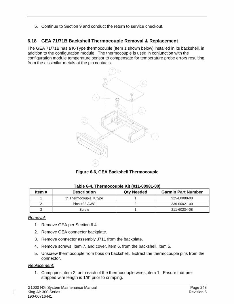
G1000 NXi System Maintenance Manual Page 248 King Air 300 Series Revision 6 190-00716-N1
5. Continue to Section 9 and conduct the return to service checkout.
6.18 GEA 71/71B Backshell Thermocouple Removal & Replacement The GEA 71/71B has a K-Type thermocouple (Item 1 shown below) installed in its backshell, in addition to the configuration module. The thermocouple is used in conjunction with the configuration module temperature sensor to compensate for temperature probe errors resulting from the dissimilar metals at the pin contacts.
Figure 6-6, GEA Backshell Thermocouple
Table 6-4, Thermocouple Kit (011-00981-00)
Item # Description Qty Needed Garmin Part Number 1 3” Thermocouple, K type 1 925-L0000-00 2 Pins #22 AWG 2 336-00021-00 3 Screw 1 211-60234-08
Removal:
1. Remove GEA per Section 6.4. 2. Remove GEA connector backplate. 3. Remove connector assembly J711 from the backplate. 4. Remove screws, item 7, and cover, item 6, from the backshell, item 5. 5. Unscrew thermocouple from boss on backshell. Extract the thermocouple pins from the
connector. Replacement:
1. Crimp pins, item 2, onto each of the thermocouple wires, item 1. Ensure that pre-stripped wire length is 1/8” prior to crimping.

G1000 NXi System Maintenance Manual Page 249 King Air 300 Series Revision 6 190-00716-N1
2. Insert newly crimped pins and wires into the appropriate connector housing location, item 4, as specified by King Air 300 Series Wiring Diagram, listed in Table 1-1.
3. Place thermocouple body, item 1, onto the backshell boss, item 5. Place the thermocouple as shown in Figure 6-6 so that the wires exit towards the bottom of the backshell.
4. Fasten thermocouple tightly to backshell using the provided screw, item 3. 5. Fasten cover, item 6, to backshell using screws, item 7. 6. Continue to Section 7.4.3 and verify that the ITT indications are valid on the MFD.
6.19 GPS/WAAS Antennas Removal:
1. Gain access to the antenna coaxial cable connector by removing the cabin interior ceiling panel. Refer to the Antenna Install drawing listed in Table 1-1.
2. Disconnect the antenna coaxial cable. 3. Remove the antenna mounting screws. 4. Remove antenna.
Reinstallation:
1. Install antenna using retained mounting screws. 2. Connect the antenna coaxial cable. 3. Fillet seal around antenna. Refer to the Antenna Install drawing listed in Table 1-1. 4. Reinstall cabin interior ceiling panel. 5. Proceed to Section 7.3.3 GPS Signal Acquisition for testing.
6.20 Diversity Transponder Antenna Removal:
1. Gain access to the antenna coaxial cable connector and mounting hardware by removing the cabin interior ceiling panel. Refer to the Antenna Install drawing listed in Table 1-1.
2. Disconnect the antenna coaxial cable. 3. Remove the two nuts and washers securing the antenna. 4. Remove antenna.
Reinstallation:
1. Install antenna using retained hardware. 2. Connect the antenna coaxial cable. 3. Fillet seal around antenna. Refer to the Antenna Install drawing listed in Table 1-1. 4. Reinstall cabin interior ceiling panel. 5. Proceed to Section 7.5.4 for testing of the GTX33D or GTX 3000.

G1000 NXi System Maintenance Manual Page 250 King Air 300 Series Revision 6 190-00716-N1
6.21 Iridium Antenna Removal:
1. Gain access to the antenna coaxial cable connector by removing the aft cabin ceiling panel. Refer to the Antenna Install drawing listed in Table 1-1.
2. Disconnect the antenna coaxial cable. 3. Remove the antenna mounting screws. 4. Remove antenna.
Reinstallation:
1. Install antenna using retained mounting screws. 2. Connect the antenna coaxial cable. 3. Fillet seal around antenna. Refer to the Antenna Install drawing listed in Table 1-1. 4. Reinstall the aft cabin ceiling panel. 5. Proceed to Section 8.18 for testing of the GSR 56.
6.22 Wi-Fi Antenna Removal:
1. Gain access to the antenna coaxial cable connector by opening the tail access door behind the aft pressure bulkhead. Refer to the Antenna Install drawing listed in Table 1-1.
2. Disconnect the antenna coaxial cable. 3. Remove the antenna mounting screws. 4. Remove antenna.
Reinstallation:
1. Install antenna using retained mounting screws. 2. Connect the antenna coaxial cable. 3. Fillet seal around antenna. Refer to the Antenna Install drawing listed in Table 1-1. 4. Secure the tail access door. 5. Proceed to Section 8.17 for testing of the GDL 59.

G1000 NXi System Maintenance Manual Page 251 King Air 300 Series Revision 6 190-00716-N1
6.23 Signal Conditioners Removal:
1. For Signal Conditioner No. 1, remove PFD1 from the instrument panel per Section 6.1. For Signal Conditioner No. 2, remove PFD2 from the instrument panel per Section 6.1.
2. Remove 3 top screws from Signal Conditioner rack. 3. Slide mounting tray out from rack and disconnect the unit connector. If needed, remove
MFD as per Section 6.1 to access the Signal Conditioner connector. 4. Remove the four mounting bolts and remove the Signal Conditioner unit. 5. If planning to reinstall the same unit, it is not necessary to disconnect the ground strap
from the unit ground stud. If replacing with a new unit, disconnect the ground strap from the removed unit and retain the ground strap and associated hardware for reinstallation on the new unit.
Reinstallation:
1. Reinstallation of the Signal Conditioners is the reverse of the removal. Reference the Main Instrument Panel Installation drawing, listed in Table 1-1, for more details.
2. Proceed to Section 7.4.3 for testing.
6.24 Instrument Panel Annunciators (Prop Synch and Standby Battery) Removal:
1. Remove MFD from the instrument panel as per Section 6.1. 2. Using a M22885/108T8234 extraction tool, disconnect connector from the back of the
switch. 3. Pull the pushbutton cap fully out of the switch body and allow the cap to rotate 90° where
it is held by the retaining element. 4. While holding the retaining sleeve (back side of the instrument panel), loosen the two
screws inside the switch body until the switch is free to come out. 5. Remove the mounting sleeve and switch from the instrument panel.
Reinstallation:
1. Reinstallation of the Prop Synch and Standby Battery switches is the reverse of the removal. Reference the Main Instrument Panel Installation drawing, listed in Table 1-1, for more details.
2. Press and hold the cockpit annunciator “Press To Test” switch located to the left of the annunciator panel, and verify the following:
• For the Standby Battery Annunciator/Switch: STBY Battery Switch legends illuminates and reflects “STANDBY BATTERY” in white, “ARM” in green, and “ON” in amber.
• For the Prop Synch Annunciator/Switch: Prop Synch Switch legends illuminates and reflects “PROP SYNC” in white, and “ON” in green.
3. Release cockpit annunciator “Press To Test” switch. 4. If further maintenance is not required, proceed to Section 9.

G1000 NXi System Maintenance Manual Page 252 King Air 300 Series Revision 6 190-00716-N1
6.25 Emergency Frequency Switch/Annunciator Removal:
1. Remove the switch plate from the pedestal using a screw driver to loosen the quarter turn fasteners.
2. Using a M22885/108T8234 extraction tool, disconnect connector from the back of the switch.
3. Pull the pushbutton cap fully out of the switch body and allow the cap to rotate 90° where it is held by the retaining element.
4. While holding the retaining sleeve (back side of the switch plate), loosen the two screws inside the switch body until the switch is free to come out.
5. Remove the mounting sleeve and switch from the switch plate. Reinstallation:
1. Reinstallation of the Emergency Frequency switch/annunciator is the reverse of the removal. Reference the Pedestal Re-Configuration drawing, listed in Table 1-1, for more details.
2. Press and hold the cockpit annunciator “Press To Test” switch located to the left of the annunciator panel, and verify the following:
• Legends illuminate and reflect “EMERG FREQ” in white and “121.5” in white. 3. Release cockpit annunciator “Press To Test” switch. 4. If further maintenance is not required, proceed to Section 9.
6.26 L-3 Avionics (BF Goodrich) PS-835(C or D Model) Emergency Battery Removal:
1. Gain access to the forward avionics compartment in the nose of the aircraft. 2. Unscrew the knurled hold-down nut to allow it to move free of the unit. 3. Remove the unit from the rack.
Reinstallation:
1. Install the emergency battery in accordance with the Electrical Equipment Install, Nose Bay drawing (refer to Master Drawing List, listed in Table 1-1, for specific drawing number). Refer to the King Air 300 Series Maintenance Manual, listed in Table 1-1, for access requirements as needed.
2. If further maintenance is not required, proceed to Section 9.
6.27 MD 302 Standby Attitude Module (SAM) The MD 302 SAM installed by this STC has two components, an electronic indicator, and a configuration module. The indicator is installed on the instrument panel, between the pilot’s PFD and the MFD. The configuration module in installed inside the 15-pin D-subminiature connector that mates to the back of electronic indicator. It is required for proper operation of the unit.

G1000 NXi System Maintenance Manual Page 253 King Air 300 Series Revision 6 190-00716-N1
6.27.1 MD 302 Electronic Standby Indicator Removal:
1. Remove MFD per Section 6.1. 2. Disconnect pitot-static plumbing from the back of the standby airspeed indicator. Take
necessary precautions to prevent foreign object debris from entering the pitot-static lines during maintenance.
3. Disconnect the electrical connector from the indicator. 4. Use a nut driver to remove the four hex head attachment screws from the front of the
indicator. 5. Remove the indicator.
Reinstallation:
1. Reinstall the electronic standby indicator referencing the Main Instrument Panel Installation drawing, listed in Table 1-1, for more details.
2. Connect the pitot-static plumbing and electrical connector. 3. Reinstall the MFD. 4. If the Configuration Module was not changed, Configuration Setup is automatic at first
power on and no additional action is required. 5. If a new unit is installed with a new configuration module, Configuration Setup per
Section 3.19 is required. 6. Test MFD per Section 9.1.

G1000 NXi System Maintenance Manual Page 254 King Air 300 Series Revision 6 190-00716-N1
6.27.2 Configuration Module Removal:
CAUTION: The Configuration Module PC Board Assembly contains sensitive electronics that can be damaged by electrostatic discharge (ESD). Appropriate precautions should be applied prior to handling this component.
1. Remove Electronic Standby Indicator per Section 6.27.1. 2. Use a Phillips screwdriver to remove the two countersunk screws from the cover on the
connector backshell. 3. Remove the backshell cover. The Configuration Module PC Board Assembly is located
directly beneath the cover. 4. Using an appropriate extraction tool remove the pins of the Configuration Module PC
Board Assembly from the D-Sub connector (D-Sub pins 15, 14, 10, and 5). 5. Remove the Configuration Module PC Board Assembly.
BACKSHELL COVER (9017274)
CFG MODULE ASSY (9017184-1)
SPRING (part of 9016479)
BACKSHELL (9017218)
SLIDE LOCK (part of 9016479)
SCREW, 4-40 (part of 9016479)
SCREW, 2-56 (90-208-10011)
SCREW, 4-40 (90-406-00011)
CABLE CLAMP (part of 9016479)
SCREW, 4-40 (part of 9016479)
TERMINAL (MS25036-149)CONNECTOR, 15 POSN,HI-DENS D-SUB (9016479)
TAPE (NOT SHOWN)(AA59163-1II0020
OR 605980-1)
Figure 6-7, MD 302 Backshell and Config Module
Reinstallation:
CAUTION: The Configuration Module PC Board Assembly contains sensitive electronics that can be damaged by electrostatic discharge (ESD). Appropriate precautions should be applied prior to handling this component.
1. The wires coming from the Configuration Module PC Board Assembly are marked as follows on the circuit board: TP1, TP2, TP3, and TP4.
2. With the D-Sub oriented up (pin locations 1-5 on top), orient the Configuration Module PC Board Assembly with the electronic parts facing UP.

G1000 NXi System Maintenance Manual Page 255 King Air 300 Series Revision 6 190-00716-N1
3. Using an appropriate insertion tool, install each pin into the rear of the D-Sub connector as follows:
• Board TP1 = config return = D-Sub pin 15
• Board TP2 = config data = D-Sub pin 14
• Board TP3 = config clock = D-Sub pin 10
• Board TP4 = config power = D-Sub pin 5 4. Bend the wires of the Configuration Module PC Board Assembly 180 degrees so that the
PC Board has its electrical components facing down as shown. Be careful not to place excess strain on the solder connections between the wires and the PC Board.
5. Capture the Configuration Module PC Board Assembly into the Backshell by placing the Backshell Cover on top of the Backshell. Ensure the holes of the cover align with the holes of the PC board and the backshell.
6. Using a Phillips screwdriver, re-install the two counter sunk screws and secure the cover.
7. Configure MD 302 unit per Section 3.19. 8. Test MFD per Section 9.1.
6.28 Mechanical Standby Indicators 6.28.1 Standby Airspeed Indicator Removal:
1. Remove MFD per Section 6.1. 2. Disconnect pitot-static plumbing from the back of the standby airspeed indicator. Take
necessary precautions to prevent foreign object debris from entering the pitot-static lines during maintenance.
3. Disconnect the electrical connector from the standby airspeed indicator. 4. Use a Phillips screwdriver to remove the attachment screws from the front of the standby
airspeed indicator. 5. Remove the standby airspeed indicator.
Reinstallation:
1. Reinstallation of the standby airspeed indicator is the reverse of the removal. Reference the Main Instrument Panel Installation drawing, listed in Table 1-1, for more details.
2. Test MFD per Section 9.1.

G1000 NXi System Maintenance Manual Page 256 King Air 300 Series Revision 6 190-00716-N1
6.28.2 Standby Altimeter Removal:
1. Remove MFD per Section 6.1. 2. Disconnect pitot-static plumbing from the back of the standby altimeter. Take necessary
precautions to prevent foreign object debris from entering the pitot-static lines during maintenance.
3. Disconnect the electrical connector from the standby altimeter. 4. Use a Phillips screwdriver to remove the attachment screws from the front of the standby
altimeter. 5. Remove the standby altimeter.
Reinstallation:
1. Reinstallation of the standby altimeter is the reverse of the removal. Reference the Main Instrument Panel Installation drawing, listed in Table 1-1, for more details.
2. Test MFD per Section 9.1.
6.28.3 Standby Attitude Indicator Ensure the standby attitude indicator gyro is not spinning—this may take 10 minutes or longer after the unit has been turned off. This unit is very delicate; handle like eggs. Refer to the 4300 Series Attitude Indicator Installation Manual, listed in Table 1-1, for more handling instructions. Removal:
1. Remove MFD per Section 6.1. 2. Disconnect the electrical connector of the standby attitude indicator. 3. Use a 0.060” 6-Spline wrench to remove the knob from the front of the standby attitude
indicator. 4. Use a Phillips screwdriver to remove the three attachment screws from the front of the
standby attitude indicator. 5. Remove the standby attitude indicator.
Reinstallation:
1. Ensure the lighting control voltage switches on rear of unit are set for 28V.
2 8 V
2. Reinstallation of the standby attitude indicator is the reverse of the removal. Reference
the Main Instrument Panel Installation drawing, listed in Table 1-1, for more details. 3. Test MFD per Section 9.1.

G1000 NXi System Maintenance Manual Page 257 King Air 300 Series Revision 6 190-00716-N1
6.29 GIA Cooling Fans Removal:
1. Gain access into the nose avionics equipment bay. 2. Disconnect the cooling fan hoses from the cooling fan. Take necessary precautions to
prevent any foreign debris from entering the fan hoses during maintenance. 3. Disconnect the electrical connector of the cooling fan. 4. Use a Phillips screwdriver to remove the attachment screws and fan inlet duct (if
installed) from the cooling fan. 5. Remove the cooling fan.
Reinstallation:
1. Reinstallation of the avionics cooling fan is the reverse of the removal. Reference the Electrical Equipment Install, Nose Bay drawing, listed in Table 1-1, for more details.
2. Test per Section 9.4.
6.30 GDU Cooling Fans Removal:
1. Remove the display associated with the cooling fan, per Section 6.1. 2. Disconnect the electrical connector of the cooling fan. 3. Use a Phillips screwdriver to remove the attachment screws from the cooling fan. 4. Remove the cooling fan.
Reinstallation:
1. Reinstallation of the Sandia GDU cooling fan is the reverse of the removal. Reference the Main Instrument Panel Installation drawing, listed in Table 1-1, for more details.
2. Test per Section 9.4.

G1000 NXi System Maintenance Manual Page 258 King Air 300 Series Revision 6 190-00716-N1
6.31 GTS 820/850 and GTS Processor Traffic Units CAUTION:
After any maintenance or modification is made to the GTS 820/850/processor TAS/TCAS cables such as replacing a connector or entire cable, be sure to adhere to all of the specifications and limitations such as minimum and maximum cable attenuation, attenuation balance between cables, phase matching etc.
Removal:
1. Gain access to the left forward avionics compartment in the nose of the aircraft. 2. Disconnect the eight coax QMA or TNC connectors. 3. Disconnect the three electrical connectors. 4. Unlock the unit from the rack by loosening the ratcheting latch mechanism. 5. Remove the unit from the rack.
Reinstallation:
1. Visually inspect the connectors to ensure there are no bent or damaged pins. Repair any damage.
2. Insert the unit into the installation rack. 3. Lock the unit into the rack by using the ratcheting latch mechanism. 4. Reconnect the eight coax QMA or TNC connectors and the three electrical connectors. 5. Close access to the left forward avionics compartment. 6. Configure and test the GTS unit per Section 7.17.
6.32 GPA 65 PA/LNA Unit Removal:
1. Remove cabin interior to access FS 158 at WL 119 on the left side of the fuselage. Reference the Antenna Install drawing listed in Table 1-1 for more details.
2. Disconnect the eight coax “quick-lock” connectors. 3. Disconnect the electrical connector. 4. Remove the four mounting screws that hold the unit to the installation brackets.
Reinstallation:
1. Visually inspect the connectors to ensure there are no bent or damaged pins. Repair any damage.
2. Reattach the unit to the mounting brackets reusing existing hardware. 3. Connect the eight coax connectors. Note the color coded bands which match the mating
connectors on the unit. 4. Reconnect the electrical connector pigtail. 5. Ensure that all connectors (coax and electrical) are locked in place. 6. Reinstall cabin interior. 7. No configuration is required for the GPA 65. Test the GTS 820/850 per Section 8.15.

G1000 NXi System Maintenance Manual Page 259 King Air 300 Series Revision 6 190-00716-N1
6.33 GA 58 Traffic Antennas Removal:
1. Gain access to the antenna coaxial cable connectors by removing the cabin interior ceiling panel. Refer to the Antenna Install drawing listed in Table 1-1.
2. Disconnect the four coaxial cable connectors. 3. Remove the antenna mounting screws. 4. Remove antenna.
Reinstallation:
1. Install antenna using retained mounting screws. 2. Connect the four coaxial cable connectors. Note the color coded bands which match the
mating connectors. 3. Fillet seal around antenna. Refer to the Antenna Install drawing listed in Table 1-1. 4. Reinstall cabin interior ceiling panel. 5. Test the GTS 820/850 or GTS Processor per Section 8.15.
6.34 GDL 59 Wi-Fi Datalink Removal:
1. Gain access to the unit based on location - a. If the unit is installed under the cabin floor, remove the cabin center floor panel at the
main entry door. Remove the remote equipment shelf or detach the two rack mount angles from the shelf. Retain all mounting hardware.
b. If the unit is installed in the tail, open the tailcone access door on the bottom of the tailcone.
2. Unlock the GDL 59 handle by loosening the Phillips screw on the handle. 3. Pull the handle upward to unlock the GDL59. Gently remove the unit from the rack.
Reinstallation:
1. Visually inspect the connectors to ensure there are no bent or damaged pins. Repair any damage.
2. Lift the handle and gently insert the GDL 59 into its rack. The handle should engage the dogleg track.
3. Press down on the GDL 59 handle to lock the unit into the rack. 4. Lock the handle to the GDL 59 body using the Philips screw. Torque the handle screw
to 10-14 in-lbs. 5. If the unit is installed under the cabin floor, reinstall the remote equipment shelf or two
rack mount angles using the retained hardware and the cabin center floor panel. 6. If the unit is installed in the tail, close the tailcone access door. 7. Configure, activate, and test the GDL 59 per Section 7.18.

G1000 NXi System Maintenance Manual Page 260 King Air 300 Series Revision 6 190-00716-N1
6.35 GSR 56 Satellite Transceiver Removal:
1. Gain access to the unit based on location - a. If the unit is installed under the cabin floor, remove the cabin center floor panel at the
main entry door. Remove the remote equipment shelf or detach the two rack mount angles from the shelf. Retain all mounting hardware.
b. If the unit is installed in the tail, open the tailcone access door on the bottom of the tailcone.
2. Unlock the unit from the rack by pulling out on the ratcheting latch mechanism and turning counter-clockwise until the latch mechanism clears the tab on the unit.
3. Slide the unit out of the rack. Reinstallation:
1. Visually inspect the connectors to ensure there are no bent or damaged pins. Repair any damage.
2. Insert the unit into the installation rack. CAUTION:
Do not use excessive force when inserting the GDL 56 into the rack. This may cause damage to occur to the connectors, unit, and/or unit rack. If heavy resistance is felt during installation, stop! Remove the GDL 56 and identify the source of resistance.
3. Lock the unit into the rack by using the ratcheting latch mechanism. 4. If the unit is installed under the cabin floor, reinstall the remote equipment shelf or two
rack mount angles using the retained hardware and the cabin center floor panel. 5. If the unit is installed in the tail, close the tailcone access door. 6. Register with Garmin Connext per Section 8.16. 7. No software or configuration loading is required for the GSR 56. Test the GSR 56
according to Section 8.18.
6.36 GRA 5500 Radar Altimeter Removal:
1. Gain access to the avionics shelf in the tail area. 2. Disconnect the electrical connector. 3. Disconnect the two coaxial cable connectors, making note of which cable is Transmit
(Tx) and which cable is Receive (Rx). 4. Pull back on the lockdown mechanism and simultaneously turn counterclockwise until
free. 5. Disengage the lockdown mechanism collar from the GRA 5500 hook and slide the GRA
5500 forward to remove the unit from the rack.

G1000 NXi System Maintenance Manual Page 261 King Air 300 Series Revision 6 190-00716-N1
Reinstallation:
1. Visually inspect the connectors to ensure there are no bent or damaged pins. Repair any damage.
2. Place the unit on the mounting rack ensuring the GRA 5500 rear feet are aligned in the mounting rack slots.
3. Slide the GRA 5500 back until the feet are fully engaged with the mounting rack. 4. Lift the lockdown mechanism collar in place on the GRA 5500 hook and hand turn the
lockdown mechanism knob clockwise until the GRA 5500 is secure and cannot reasonably be ratcheted any tighter by hand.
5. Connect the electrical connector. 6. Connect the two coaxial cable connectors. 7. For integrated installations (using a RS-422 connection to GIA2), configure and test the
GRA 5500 according to Section 7.16. For non-integrated installations (using Arinc 429 connections), configure and test per Section 3.17.
6.37 GSD 41 Data Concentrator Removal:
1. Gain access to the avionics shelf in the tail area. 2. Unlock the unit from the rack by loosening the ratcheting latch mechanism. 3. Remove the unit from the rack.
Reinstallation:
1. Visually inspect the connectors to ensure there are no bent or damaged pins. Repair any damage.
2. Insert the unit into the installation rack. CAUTION:
Do not use excessive force when inserting the GSD 41 into the rack. This may cause damage to occur to the connectors, unit, and/or unit rack. If heavy resistance is felt during installation, stop! Remove the GSD 41 and identify the source of resistance.
3. Lock the unit into the rack by using the ratcheting latch mechanism. 4. Configure the GSD 41 according to Section 7.20.

G1000 NXi System Maintenance Manual Page 262 King Air 300 Series Revision 6 190-00716-N1
7. GARMIN G1000 LRU REPLACEMENT/CONFIGURATION & TESTING This section provides procedures to be followed after a piece of G1000 equipment is replaced. At the beginning of each LRU section, instructions are given to guide the technician for various removal/replacement scenarios. These instructions define necessary procedures to be followed for situations where original equipment was reinstalled as well as for situations where new equipment (new serial number) is installed.
NOTE Garmin recommends the use of SanDisk brand SD cards to load G1000 software and configuration files. If another brand of card is used, and software loading problems occur, replace the card with a SanDisk brand card and reattempt the software load.
CAUTION Connect a ground power unit to the aircraft for software loading. DO NOT RELY ON THE AIRCRAFT BATTERY TO LOAD SOFTWARE. DO NOT USE A BATTERY CHARGER AS AN EXTERNAL POWER SOURCE DUE TO ELECTRICAL NOISE IT MAY INJECT IN THE G1000 SYSTEM. DO NOT ALLOW POWER TO BE REMOVED FROM THE SYSTEM WHEN LOADING SOFTWARE! Remove power only when told to do so by the following procedure. Power loss during a software upgrade may cause a LRU to become corrupted and unresponsive requiring replacement. Remove power only when told to do so in the procedure. All displays should be in the same mode (configuration or normal), unless instructed differently. If an incorrect configuration file is loaded at any time in this section, STOP and start the configuration load over using Section 3.8.

G1000 NXi System Maintenance Manual Page 263 King Air 300 Series Revision 6 190-00716-N1
7.1 GDU 1050A/1550 PFD & MFD Original Display Reinstalled
If the removed display(s) are re-installed in their original positions, no software or configuration loading is required. This does not include units that were returned for repair as their software and configuration files are deleted during the repair testing process. Continue to the PFD/MFD Test procedure, Section 7.1.7. Original PFD Displays Installed in Opposite Locations for Troubleshooting
If the PFD 1 and PFD 2 are installed in opposite positions, no software or configuration loading is required. Continue to the PFD/MFD Test procedure, Section 7.1.7. New Repair or Exchange Display(s) Installed
If a new, repaired or exchanged GDU is installed, the correct software and configuration files must be loaded to the unit.
7.1.1 LRU Replacement Procedure PFD1 1. Open the MFD, PFD 1 (PRI), PFD 1 (SEC), and PFD 2 circuit breakers. 2. Apply power to the G1000 system by connecting external power to the aircraft to
energize the aircraft and avionics electrical busses. 3. Turn on Avionics electrical busses. 4. Power on PFD2, MFD, and PFD1 in configuration mode. 5. Using the MFD, scroll to the LRU replacement page. 6. Activate the curser and select PFD1 in the LRU dropdown box. 7. Press the CHK All softkey. 8. Press the Load softkey. 9. Press ENT to acknowledge the process was complete. 10. Deactivate the curser. 11. Scroll to the Configuration Manager page. 12. Press the CNFM CFG softkey. 13. Select ok when prompted to “Confirm configuration as expected configuration” 14. Power cycle the system. Verify there are no red-Xs or system alerts. 15. If red-Xs or system alerts are present, troubleshoot as necessary using Section 5 or re-
load the system using the legacy method in Section 3.8. 16. If there are no red-Xs or system alerts, continue to Section 7.1.7.
7.1.2 Legacy Replacement Procedure PFD1 (Alternate Method) A full system configuration re-load is required when a new, repaired, or exchanged display is installed using this method. This includes all options and feature enablements. To complete this procedure, continue to Section 3.8.

G1000 NXi System Maintenance Manual Page 264 King Air 300 Series Revision 6 190-00716-N1
7.1.3 LRU Replacement Procedure PFD2 1. Open the MFD, PFD 1 (PRI), PFD 1 (SEC), and PFD 2 circuit breakers. 2. Remove SD cards from top and bottom slots of PFD2, MFD, and PFD1 if present. 3. Apply power to the G1000 system by connecting external power to the aircraft to
energize the aircraft and avionics electrical busses. 4. Turn on Avionics electrical busses. 5. Power on PFD2, MFD, and PFD1 in configuration mode. 6. Using the MFD, scroll to the LRU replacement page. 7. Activate the curser and select PFD2 in the LRU dropdown box. 8. Press the CHK All softkey. 9. Press the Load softkey. 10. Press ENT to acknowledge the process was complete. 11. Deactivate the curser. 12. Scroll to the Configuration Manager page. 13. Press the CNFM CFG softkey. 14. Select ok when prompted to “Confirm configuration as expected configuration” 15. Power cycle the system. Verify there are no red-Xs or system alerts. 16. If red-Xs or system alerts are present, troubleshoot as necessary using Section 5 or re-
load the system using the legacy method in Section 3.8. 17. If there are no red-Xs or system alerts, continue to Section 7.1.7.
7.1.4 Legacy Replacement Procedure PFD2 (Alternate Method) A full system configuration re-load is required when a new, repaired, or exchanged display is installed using this method. This includes all options and feature enablements. To complete this procedure, perform Section 3.8.
7.1.5 LRU Replacement Procedure MFD NOTE
Anytime the MFD is replaced, all databases will have to be reloaded.
1. Open the MFD, PFD 1 (PRI), PFD 1 (SEC), and PFD 2 circuit breakers. 2. Remove SD cards from top and bottom slots of PFD2, MFD, and PFD1 if present. 3. Apply power to the G1000 system by connecting external power to the aircraft to
energize the aircraft and avionics electrical busses. 4. Turn on Avionics electrical busses. 5. Power on PFD2, MFD, and PFD1 in configuration mode. 6. Using the PFD1, scroll to the LRU replacement page.

G1000 NXi System Maintenance Manual Page 265 King Air 300 Series Revision 6 190-00716-N1
7. Activate the curser and select MFD in the LRU dropdown box. 8. Press the CHK All softkey. 9. Press the Load softkey. 10. Press ENT to acknowledge the process was complete. 11. Deactivate the curser. 12. Scroll to the Configuration Manager page. 13. Press the CNFM CFG softkey. 14. Select ok when prompted to “Confirm configuration as expected configuration” 15. Power cycle the system. Verify there are no red-Xs or system alerts. 16. If red-Xs or system alerts are present, troubleshoot as necessary using Section 5 or re-
load the system using the legacy method in Section 3.8. 17. Install databases Section 3.14 to re-load databases. 18. After databases are re-loaded, continue to Section 7.1.7.
7.1.6 Legacy Replacement Procedure MFD (Alternate Method) A full system configuration re-load is required when a new, repaired, or exchanged display is installed using this method. This includes all options and feature enablements. To complete this procedure, perform Section 3.8.
7.1.7 PFD/MFD Test 1. Allow displays to initialize for ~1 minute. 2. Check that all COM/NAV display fields are valid in the top corners of both PFDs. 3. Check that attitude, heading, altitude, airspeed, vertical speed and OAT fields are valid
within 2 minutes of power up on both PFDs. 4. Press the Sensor softkey on each PFD and switch between ADC1 and ADC2. Verify
that data from both GDC air data computers is valid on both displays. 5. Press the Sensor softkey on each PFD and switch between AHRS1 and AHRS2. Verify
that data from both GSU 75 or GRS 77/7800 is valid on both displays. 6. Check that the engine instrument fields are valid on the MFD.
Figure 7-1, G1000 Normal Mode Check

G1000 NXi System Maintenance Manual Page 266 King Air 300 Series Revision 6 190-00716-N1
7. Push the red DISPLAY BACKUP button on GMA1. Verify that the pilot-side PFD and MFD displays enter reversion mode. MFD should have valid altitude, airspeed, vertical speed, COM1, COM2, NAV1, NAV2 and engine instruments.
8. De-activate pilot-side reversion mode by pushing the DISPLAY BACKUP button. Verify PFD 1 and MFD return to normal display modes.
9. Repeat Step 1 using GMA2. Ensure that PFD 2 and MFD enter reversion mode and MFD displays valid altitude, airspeed, vertical speed, COM1, COM2, NAV1, NAV2 and engine instruments.
10. De-activate co-pilot’s side reversion mode by pushing the DISPLAY BACKUP button. Verify PFD 2 and MFD return to normal display modes.
11. Select the Map – TAWS Map page on the MFD. 12. Verify that the title at the top of the page reads “Map – TAWS-B” or “Map-TAWS-A”. If
TAWS has not been enabled, the title will read “Map – Terrain Proximity” or “Map – Terrain”.
13. Press the MENU button and select “Test TAWS” from the pop-up menu. 14. After the TAWS test has completed, verify that “TAWS System Test Okay” is heard over
the cockpit speaker. 15. If no other service is to be performed, perform final return-to-service test as specified in
Section 9.

G1000 NXi System Maintenance Manual Page 267 King Air 300 Series Revision 6 190-00716-N1
7.2 GMA 1347D or GMA 1360D Audio Panel Original GMA 1347D or GMA 1360D Reinstalled
No software/configuration loading or testing is required if the removed GMA 1347D or GMA 1360D is re-installed. This does not include units that were returned for repair as their software and configuration files are deleted during the repair testing process. Continue to the final return-to-service checks in Section 9. Original GMA 1347D or GMA 1360D Installed in Opposite Locations for Troubleshooting
If the original GMA #1 and GMA #2 are installed in opposite locations, configuration loading is required. See Section 7.2.1. New, Repaired or Exchange GMA 1347D or GMA 1360D Installed
If a new, repaired or exchanged GMA 1347D or GMA 1360D is installed, the correct software and configuration files must be loaded to the unit. See Section 7.2.1.
7.2.1 LRU Replacement Procedure GMA 1 or GMA 2 1. Open the MFD, PFD 1 (PRI), PFD 1 (SEC), and PFD 2 circuit breakers. 2. Apply power to the G1000 system by connecting external power to the aircraft to
energize the aircraft and avionics electrical busses. 3. Turn on Avionics electrical busses. 4. Power on PFD2, MFD, and PFD1 in configuration mode. 5. Using the PFD1, scroll to the LRU replacement page. 6. Activate the curser and select GMA1 or GMA2, whichever was replaced in the LRU
dropdown box 7. Press the CHK All softkey. 8. Press the Load softkey. 9. Press ENT to acknowledge the process was complete. 10. Deactivate the curser. 11. Scroll to the Configuration Manager page. 12. Press the CNFM CFG softkey. 13. Select ok when prompted to “Confirm configuration as expected configuration” 14. Power cycle the system. Verify there are no red-Xs or system alerts. 15. If red-Xs or system alerts are present, troubleshoot as necessary using Section 5 or re-
load the system using the legacy method in Section 7.2.2. 16. If there are no red-Xs or system alerts, continue to Section 7.2.3.

G1000 NXi System Maintenance Manual Page 268 King Air 300 Series Revision 6 190-00716-N1
7.2.2 Legacy Replacement Procedure GMA 1 or GMA 2 (Alternate Method) To load the GMA complete the following subsections in order as they apply to the aircraft.
7.2.2.1 01) Baseline (For GMA 1 or GMA 2 replacement) 1. Insert the software loader card in the top slot of PFD1. 2. Power on PFD2, MFD, and PFD1 in configuration mode. 3. Select NO when “Do you want to update system files” is displayed on the screen of
PFD1. 4. Select the “SYSTEM UPLOAD” page using the small FMS knob on PFD1. 5. Activate cursor and rotate the small FMS knob to display the drop down menu. Rotate
the small FMS knob to highlight “01) Baseline” and press ENT key on PFD1. 6. Rotate the small FMS knob to display the drop down menu. Rotate the large FMS knob
to highlight the appropriate baseline configuration, then press the ENT key on PFD1. 7. Press the CLR ALL softkey. 8. Use the large FMS knob to scroll to GMA1 or GMA2 whichever was replaced. 9. Highlight the software box and press the ENT key. 10. Highlight the Configuration box and press the ENT key. 11. Press “Load” softkey. 12. Monitor load progress. Verify software load completes without errors as indicated by the
following: 13. Green “PASS” in the Configuration and Software columns for each item loaded. 14. “Upload Complete………….”COMPLETE” in the summary box. 15. Acknowledge the prompt by pushing the ENT key.
7.2.2.2 07) Connext - SXM (For GMA 1 or GMA 2 replacement and aircraft equipped with a GDL 59 and/or GSR 56 only)
1. Scroll the curser to the Group window and select “07) Connext - SXM 2. Press the ENT key. 3. In the ITEM window highlight the installed GDL 59 and/or GSR 56 configuration and
press the ENT key on PFD1. 4. Press the CLR ALL softkey. 5. Scroll the curser to GMA1 or GMA 2 configuration box, whichever was replaced, and
press the ENT key to check the box. 6. Press “Load” softkey. 7. Monitor load progress. Verify software load completes without errors as indicated by the
following:
• Green “PASS” in the Configuration and Software columns for each item loaded.
• “Upload Complete………….”COMPLETE” in the summary box. 8. Acknowledge the prompt by pushing the ENT key.

G1000 NXi System Maintenance Manual Page 269 King Air 300 Series Revision 6 190-00716-N1
7.2.2.3 11) Non Garmin Options (For GMA 1 or GMA 2 replacement and aircraft equipped with a ADF only)
1. Scroll the curser to the Group window and select 11) Non-Garmin options. 2. Press the ENT key. 3. In the ITEM window highlight King Air – ADF Option and press the ENT key on PFD1. 4. Press the CLR ALL softkey. 5. Scroll the curser to GMA 1 or GMA 2 configuration box, whichever was replaced, and
press the ENT key to check the box. 6. Press “Load” softkey. 7. Monitor load progress. Verify software load completes without errors as indicated by the
following:
• Green “PASS” in the Configuration and Software columns for each item loaded.
• “Upload Complete………….”COMPLETE” in the summary box. 8. Acknowledge the prompt by pushing the ENT key.
7.2.2.4 11) Non Garmin Options (For GMA 1 or GMA 2 replacement and aircraft equipped with a DME only)
1. Scroll the curser to the ITEM window highlight King Air – DME Option and press the ENT key on PFD1.
2. Press the CLR ALL softkey. 3. Scroll the curser to GMA 1 or GMA 2 configuration box, whichever was replaced, and
press the ENT key to check the box. 4. Press “Load” softkey. 5. Monitor load progress. Verify software load completes without errors as indicated by the
following:
• Green “PASS” in the Configuration and Software columns for each item loaded.
• “Upload Complete………….”COMPLETE” in the summary box. 6. Acknowledge the prompt by pushing the ENT key.
7.2.2.5 Configuration Manager Update 1. With the system still in configuration mode, scroll to the Configuration Manager page on
PFD 1. 2. Press the CNFM CFG softkey. 3. Select ok when prompted to “Confirm configuration as expected configuration” 4. Power cycle the system. Verify there are no red-Xs or system alerts. 5. If red-Xs or system alerts are present, troubleshoot as necessary using Section 5. 6. If there are no red-Xs or system alerts, continue to Section 7.2.3.

G1000 NXi System Maintenance Manual Page 270 King Air 300 Series Revision 6 190-00716-N1
7.2.3 GMA 1347D/1360D Test Except for marker beacon operation, an in-aircraft checkout may be performed in the aircraft with known good microphone, headset, and speaker.
7.2.3.1 Crew Intercom System (ICS) Check 1. Ensure that the MAN SQ key is off (no light). 2. Adjust GMA1 and GMA2 ICS volume to a comfortable level. 3. Turn off the speaker output by unselecting the SPK button on each GMA. 4. Ensure the PASS ICS button is unselected. 5. Plug in a headset to any cabin audio jack. 6. Plug in a headset to the pilot and copilot audio jacks and verify the following:
• Two way communication can be established between the pilot and copilot using ICS.No communication between the cabin and cockpit can be established while using ICS.Cabin ICS cannot be heard by the pilot or copilot.
7.2.3.2 Passenger Address (PA) Check 1. On both GMAs select COM1 MIC and AUDIO. 2. Verify an active (green) COM1 frequency is displayed on both PFDs. 3. On GMA1, select PA and verify the PA select annunciator is illuminated on GMA1.
Verify COM1 active frequency is displayed white on the PFD1. 4. On GMA 2, select PA and verify the PA select annunciator is illuminated on GMA2.
Verify COM1 active frequency is displayed white on the PFD2. 5. Initiate passenger address using pilot’s headset boom mic by keying the pilots PTT.
Verify clear PA audio can be heard over cabin speaker and passenger headsets, PA selected annunciator on GMA1 flashes ~ once per second during PA address. Repeat using pilot hand mic.
6. Initiate passenger address using copilot’s headset boom mic by keying the copilots PTT. Verify clear PA audio can be heard over cabin speaker and passenger headsets, PA selected annunciator on GMA2 flashes ~ once per second during PA address. Repeat using copilot hand mic.
7.2.3.3 Transceiver Operational Check Perform a ramp test radio check by exercising the installed transceivers, microphone, microphone key and audio over the headphones and speaker. Verify that communications are clear and PTT operation is correct for each pilot position.
1. On the pilot’s audio panel, select the audio source corresponding to each installed avionics unit (i.e. NAV1, NAV2, COM1, COM2, ADF and DME) and check for audio over the pilot’s headset.
2. Press the SPKR key on pilot’s audio panel and verify that the selected audio is heard over the pilot’s speaker.

G1000 NXi System Maintenance Manual Page 271 King Air 300 Series Revision 6 190-00716-N1
3. On the copilot’s audio panel, select the audio source corresponding to each installed avionics unit (i.e. NAV1, NAV2, COM1, COM2, ADF and DME) and check for audio over the copilot’s headset.
4. Press the SPKR key on copilot’s audio panel and verify that the selected audio is heard over the copilot’s speaker.
7.2.3.4 Failsafe Operation Check – GMA1 1. Turn the GMA1 off by pulling the AUDIO NO 1 circuit breaker. This directs all COM 1
phone audio, MIC audio and MIC key to the pilot’s position. 2. Check the failsafe operation by exercising the COM 1 boom mic, hand mic, microphone
key and audio over the headphones. For GMA 1360D units, the volume is preset and cannot be changed by the pilot. For GMA 1347D units, all volume control for the COM audio is through the PFD volume control. Verify proper operation of COM 1 using the failsafe operation.
3. Close the AUDIO NO 1 circuit breaker to continue testing.
7.2.3.5 Failsafe Operation Check – GMA2 1. Turn the GMA2 off by pulling the AUDIO NO 2 circuit breaker. This directs all COM 2
phone audio, MIC audio and MIC key to the co-pilot’s position. 2. Check the failsafe operation by exercising the COM 2 boom mic, hand mic, microphone
key and audio over the headphones. For GMA 1360D units, the volume is preset and cannot be changed by the crew. For GMA 1347D units, all volume control for the COM audio is through the PFD volume control. Verify proper operation of COM 2 using the failsafe operation.
3. Close the AUDIO NO 2 circuit breaker to continue testing.
7.2.3.6 Marker Beacon Test 1. Using a ramp tester, simulate the outer marker, middle marker, and inner marker signals
by following the test equipment manufacturer’s instructions. Verify that each marker audio signal is present over the pilot and co-pilot headphones and speaker.
2. Verify that the outer, middle, and inner annunciations appear on PFD 1 and PFD 2 when the corresponding signal is applied. Marker beacon annunciations ( , , and ) appear at the upper left corner of the altitude indicator on the PFD. Operate the MKR MUTE key on the #1 and #2 GMA and ensure that the audio signal is muted.
3. If no other service is to be performed, continue to the return-to-service checks in Section 9.

G1000 NXi System Maintenance Manual Page 272 King Air 300 Series Revision 6 190-00716-N1
7.2.4 Landing Gear Aural Alert Check This check should be conducted in conjunction with the Phase 2 and Phase 4 Landing Gear Retraction, Warning Horn check, in the existing King Air Maintenance Program.
NOTE This procedure is applicable only to aircraft equipped with a tone generator as part of the aircraft audio system. Refer to the appropriate aircraft wiring diagrams to determine if a tone generator is installed. This check can be accomplished in conjunction with the Weight on Wheels and Low Speed Awareness Band Test in Section 8.12.
1. Conduct the Landing Gear Retraction, Warning Horn check as stated in the King Air 300 Series Maintenance Manual, listed in Table 1-1.
2. Verify that the aural tone is played through the G1000 audio system and through both cockpit speakers.
7.2.5 SiriusXM Audio Suppression Check This procedure is applicable only to aircraft that have Sirius XM radio subscriptions.
WARNING The following steps require movement of the landing gear. Ensure aircraft is safe for the operation of the landing gear before proceeding.
1. Jack aircraft to allow operation of landing gear (reference King Air 300 Series
Maintenance Manual Chapter 7-00-00). 2. Ensure both left and right throttles are at IDLE position. 3. While monitoring pilot and copilot Sirius XM audio, retract landing gear to the full up and
locked position and verify the following:
• landing gear warning horn is active
• XM audio is muted in the pilot and co-pilot stations 4. Increase both left and right throttles forward of IDLE position (towards takeoff position)
and verify the following:
• landing gear warning horn is not active
• XM audio can be heard (For aircraft not equipped with a tone generator, deselect mute softkey or adjust Sirius XM volume to restore Sirius XM audio)

G1000 NXi System Maintenance Manual Page 273 King Air 300 Series Revision 6 190-00716-N1
5. Extend landing gear to the full down and locked position and return both throttles to idle position.
6. Remove aircraft from jacks. 7. Ensure STALL WARN circuit breaker is closed. 8. While monitoring pilot and copilot Sirius XM audio, press the STALL WARN TEST switch
and verify the following:
• Stall warning tone is active
• XM audio is muted in the pilot and co-pilot stations 9. Release the STALL WARN TEST switch and verify the following:
• Stall warning tone is not active.
• XM audio can be heard (For aircraft not equipped with a tone generator, deselect mute softkey or adjust Sirius XM volume to restore Sirius XM audio.)

G1000 NXi System Maintenance Manual Page 274 King Air 300 Series Revision 6 190-00716-N1
7.3 GIA 63W or GIA 64E Integrated Avionics Unit Original GIA 63W(s) or GIA 64E(s) Reinstalled
No software or configuration loading is required if the removed GIA is re-installed in its original position (GIA1 and GIA2 in their original racks). This does not include units that were returned for repair as their software and configuration files are deleted during the repair testing process. Continue to the return-to-service checks in Section 9. Original GIA 63Ws or GIA 64Es Swapped for Troubleshooting
No software loading is required if the originally installed GIA units are re-installed in opposite positions (GIA1 and GIA2 in opposite unit racks). However, configuration loading is required. See Section 7.3.1. New, Repaired or Exchange GIA 63W(s) or GIA 64E(s) Installed
If a new, repaired or exchange GIA 63W or GIA 64E is installed, the correct software and configuration files must be loaded to the unit. See Section 7.3.1.
7.3.1 LRU Replacement Procedure GIA1 or GIA2 1. Open the MFD, PFD 1 (PRI), PFD 1 (SEC), and PFD 2 circuit breakers. 2. Apply power to the G1000 system by connecting external power to the aircraft to
energize the aircraft. 3. Turn on Avionics electrical busses. 4. Power on PFD2, MFD, and PFD1 in configuration mode. 5. Using the PFD1, scroll to the LRU replacement page. 6. Activate the curser and select GIA1 or GIA2, whichever was replaced in the LRU
dropdown box. 7. Press the CHK All softkey. 8. Press the Load softkey. 9. Press ENT to acknowledge the process was complete. 10. Select Com1 or 2 in the LRU dropdown box. 11. Press the CHK All softkey. 12. Press the Load softkey. 13. Press ENT to acknowledge the process was complete. 14. Select GPS1 or 2 in the LRU dropdown box. 15. Press the CHK All softkey. 16. Press the Load softkey. 17. Press ENT to acknowledge the process was complete. 18. Select Nav1 or 2 in the LRU dropdown box. 19. Press the CHK All softkey. 20. Press the Load softkey. 21. Press ENT to acknowledge the process was complete. 22. Deactivate the curser. 23. Scroll to the Configuration Manager page.

G1000 NXi System Maintenance Manual Page 275 King Air 300 Series Revision 6 190-00716-N1
24. Press the CNFM CFG softkey. 25. Select ok when prompted to “Confirm configuration as expected configuration” 26. Power cycle the system. Verify there are no red-Xs or system alerts. 27. If red-Xs or system alerts are present, troubleshoot as necessary using Section 5 or re-
load the system using the legacy method in Section 7.3.2. 28. If there are no red-Xs or system alerts, continue to Section 7.3.3.
7.3.2 Legacy Replacement Procedure GIA1 or GIA2 (Alternate Method) To load the GIA complete the following subsections in order as they apply to the aircraft.
7.3.2.1 01) Baseline (For GIA 1 or GIA 2 replacement) 1. Insert the software loader card in the top slot of PFD1. 2. Power on PFD2, MFD, and PFD1 in configuration mode. 3. Select NO when “Do you want to update system files” is displayed on the screen of
PFD1. 4. Select the “SYSTEM UPLOAD” page using the small FMS knob on PFD1. 5. Activate the cursor and rotate the small FMS knob to display the drop down menu.
Rotate the large FMS knob to highlight “01) Baseline” and press ENT key on PFD1. 6. Rotate the small FMS knob to display the drop down menu. Rotate the large FMS knob
to highlight the appropriate baseline configuration, then press ENT key on PFD1. 7. Press the CLR ALL softkey. 8. Use the large FMS knob to scroll to GIA 1 or GIA 2 whichever was replaced. 9. Highlight the software box and press the ENT key to check the box. 10. Highlight the Configuration box and press the ENT key to check the box. 11. Scroll to GIA 1 or GIA 2 Region Config, whichever was replaced. 12. Highlight the Configuration box and press the ENT key to check the box. 13. Scroll to NAV 1 or NAV 2, whichever was replaced. 14. Highlight the Software box and press the ENT key to check the box. 15. Scroll to COM 1 or COM 2, whichever was replaced. 16. Highlight the Software box and press ENT key to check the box. 17. Highlight the Configuration box and press the ENT key to check the box. 18. Scroll to GPS/WAAS 1 or GPS/WAAS 2, whichever was replaced. 19. Highlight the Software box and press the ENT key to check the box. 20. Scroll to GIA 1 or GIA 2 AUDIO, whichever was replaced. 21. Highlight the Software box and press the ENT key to check the box. 22. Scroll to AUDIO CONFIG. 23. Highlight the Configuration box and press the ENT key to check the box.

G1000 NXi System Maintenance Manual Page 276 King Air 300 Series Revision 6 190-00716-N1
24. Press “Load” softkey. 25. Monitor load progress. Verify software load completes without errors as indicated by the
following:
• Green “PASS” in the Configuration and Software columns for each item loaded.
• “Upload Complete………….”COMPLETE” in the summary box. 26. Acknowledge the prompt by pushing the ENT key.
7.3.2.2 03) 300 Series Engine-Prop (For GIA 1 or GIA 2 replacement) 1. Scroll the curser to the Group window and select “03) 300 Series Engine-Prop”. 2. Press the ENT key. 3. In the ITEM window highlight the aircraft’s engine and prop combination and press the
ENT key on PFD1. 4. Press the CLR ALL softkey. 5. Scroll the curser to GIA1 or GIA 2 configuration box, whichever was replaced, and press
the ENT key to check the box. 6. Press “Load” softkey. 7. Monitor load progress. Verify software load completes without errors as indicated by the
following:
• Green “PASS” in the Configuration and Software columns for each item loaded.
• “Upload Complete………….”COMPLETE” in the summary box. 8. Acknowledge the prompt by pushing the ENT key.
7.3.2.3 04) AHRS – Air Data (For GIA 1 or GIA 2 replacement) NOTE
The aircraft will be equipped with dual GSU 75 ADAHRS or a combination of GRS and GDC. If the aircraft is equipped with the combination GRS and GDC, the installer will need to load the GRS file then load the GDC file using the following procedure. If the aircraft is equipped with GSU 75s, the GSU 75 is the only file that needs to be loaded.
1. Scroll the curser to the Group window and select “04) AHRS – Air Data. 2. Press the ENT key. 3. In the ITEM window highlight the installed GDC selection or GSU 75B and press the
ENT key on PFD1. 4. Press the CLR ALL softkey. 5. Scroll the curser to GIA1 or GIA 2 configuration box, whichever was replaced, and press
the ENT key to check the box. 6. Press “Load” softkey. 7. Monitor load progress. Verify software load completes without errors as indicated by the
following:
G1000 NXi System Maintenance Manual Page 277 King Air 300 Series Revision 6 190-00716-N1
• Green “PASS” in the Configuration and Software columns for each item loaded.
• “Upload Complete………….”COMPLETE” in the summary box. 8. Acknowledge the prompt by pushing the ENT key 9. Repeat steps 1-8 if there are GRS 77s or GRS 7800s installed. Select the
installed GRS unit in Step 3.
7.3.2.4 05) Autopilot (For GIA 1 or GIA 2 replacement) 1. Scroll the curser to the Group window and select “05) Autopilot. 2. Press the ENT key. 3. In the ITEM window highlight the installed autopilot configuration and press the ENT key
on PFD1. 4. Press the CLR ALL softkey. 5. Scroll the curser to GIA CERT software box, and press the ENT key to check the box. 6. If King Air 300/B300 Series GFC700 – ESP Installation (No AOA) was selected in the
ITEM window, scroll the curser to select GIA 1 or GIA 2 configuration box, whichever was replaced. Press the ENT to check the box.
7. Press “Load” softkey. 8. Monitor load progress. Verify software load completes without errors as indicated by the
following:
• Green “PASS” in the Configuration and Software columns for each item loaded.
• “Upload Complete………….”COMPLETE” in the summary box. 9. Acknowledge the prompt by pushing the ENT key.
7.3.2.5 06) Garmin Transponders (For GIA 1 or GIA 2 replacement) 1. Scroll the curser to the Group window and select 06) Garmin Transponders. 2. Press the ENT key. 3. In the ITEM window highlight the installed transponder configuration and press the ENT
key on PFD1. 4. Press the CLR ALL softkey. 5. Scroll the curser to GIA1 or GIA 2 configuration box, whichever was replaced, and press
the ENT key to check the box. 6. Press “Load” softkey. 7. Monitor load progress. Verify software load completes without errors as indicated by the
following:
• Green “PASS” in the Configuration and Software columns for each item loaded.
• “Upload Complete………….”COMPLETE” in the summary box. 8. Acknowledge the prompt by pushing the ENT key.

G1000 NXi System Maintenance Manual Page 278 King Air 300 Series Revision 6 190-00716-N1
7.3.2.6 07) Connext – SXM (For GIA 1 replacement and aircraft equipped with a standalone GSR 56 only)
1. Scroll the curser to the Group window and select 07) Connext – SXM. 2. Press the ENT key. 3. In the ITEM window highlight the installed standalone GSR 56 configuration and press
the ENT key on PFD1. 4. Press the CLR ALL softkey. 5. Scroll the curser to GIA1 configuration box and press the ENT key to check the box. 6. Press “Load” softkey. 7. Monitor load progress. Verify software load completes without errors as indicated by the
following:
• Green “PASS” in the Configuration and Software columns for each item loaded.
• “Upload Complete………….”COMPLETE” in the summary box. 8. Acknowledge the prompt by pushing the ENT key.
7.3.2.7 08) Radar (For GIA 2 replacement and aircraft equipped with a Garmin GRA 5500 radar altimeter only)
1. Scroll the curser to the Group window and select 08) Radar. 2. Press the ENT key. 3. In the ITEM window highlight King Air - GRA 5500 Radar Altimeter and press the ENT
key on PFD1. 4. Press the CLR ALL softkey. 5. Scroll the curser to GIA 2 configuration box, and press the ENT key to check the box. 6. Press “Load” softkey. 7. Monitor load progress. Verify software load completes without errors as indicated by the
following:
• Green “PASS” in the Configuration and Software columns for each item loaded.
• “Upload Complete………….”COMPLETE” in the summary box. 8. Acknowledge the prompt by pushing the ENT key.
7.3.2.8 11) Non Garmin Options (For GIA 2 replacement and aircraft equipped with a ADF only)
1. Scroll the curser to the Group window and select 11) Non-Garmin options. 2. Press the ENT key. 3. In the ITEM window highlight King Air – ADF Option and press the ENT key on PFD1. 4. Press the CLR ALL softkey. 5. Scroll the curser to GIA 2 configuration box, and press the ENT key to check the box.

G1000 NXi System Maintenance Manual Page 279 King Air 300 Series Revision 6 190-00716-N1
6. Press “Load” softkey. 7. Monitor load progress. Verify software load completes without errors as indicated by the
following:
• Green “PASS” in the Configuration and Software columns for each item loaded.
• “Upload Complete………….”COMPLETE” in the summary box. 8. Acknowledge the prompt by pushing the ENT key.
7.3.2.9 11) Non Garmin Options (For GIA 1 replacement and aircraft equipped with a DME only)
1. Scroll the curser to the ITEM window highlight King Air – DME Option and press the ENT key on PFD1.
2. Press the CLR ALL softkey. 3. Scroll the curser to GIA 1 configuration box, and press the ENT key to check the box. 4. Press “Load” softkey. 5. Monitor load progress. Verify software load completes without errors as indicated by the
following:
• Green “PASS” in the Configuration and Software columns for each item loaded.
• “Upload Complete………….”COMPLETE” in the summary box. 6. Acknowledge the prompt by pushing the ENT key.
7.3.2.10 11) Non Garmin Options (For GIA 2 replacement and aircraft equipped with a non-Garmin radar altimeter only)
1. Scroll the curser to the ITEM window highlight King Air – RAD ALT Option (429 Interface) and press the ENT key on PFD1.
2. Press the CHK ALL softkey. 3. Press “Load” softkey. 4. Monitor load progress. Verify software load completes without errors as indicated by the
following:
• Green “PASS” in the Configuration and Software columns for each item loaded.
• “Upload Complete………….”COMPLETE” in the summary box. 5. Acknowledge the prompt by pushing the ENT key.
7.3.2.11 11) Non Garmin Options (For GIA 1 or GIA 2 replacement and aircraft equipped with a non-Garmin TCAS II system only)
1. Scroll the curser to the ITEM window highlight King Air – Non-Garmin TCAS II System Option and press the ENT key on PFD1.
2. Press the CLR ALL softkey.

G1000 NXi System Maintenance Manual Page 280 King Air 300 Series Revision 6 190-00716-N1
3. Scroll the curser to GIA 1 or GIA 2 configuration box, whichever was replaced, and press the ENT key to check the box.
4. Press “Load” softkey. 5. Monitor load progress. Verify software load completes without errors as indicated by the
following:
• Green “PASS” in the Configuration and Software columns for each item loaded.
• “Upload Complete………….”COMPLETE” in the summary box. 6. Acknowledge the prompt by pushing the ENT key.
7.3.2.12 Non Garmin Options (For GIA 2 replacement and aircraft equipped with a non-Garmin traffic system only)
1. Scroll the curser to the ITEM window highlight King Air – Traffic System Option (429 Interface) and press the ENT key on PFD1.
2. Press the CHK ALL softkey. 3. Press “Load” softkey. 4. Monitor load progress. Verify software load completes without errors as indicated by the
following:
• Green “PASS” in the Configuration and Software columns for each item loaded.
• “Upload Complete………….”COMPLETE” in the summary box. 5. Acknowledge the prompt by pushing the ENT key.
7.3.2.13 Non Garmin Options (For GIA 2 replacement and aircraft equipped with a lightning detection system only)
1. Scroll the curser to the ITEM window highlight King Air – Lightning System Option and press the ENT key on PFD1.
2. Press the CHK ALL softkey. 3. Press “Load” softkey. 4. Monitor load progress. Verify software load completes without errors as indicated by the
following:
• Green “PASS” in the Configuration and Software columns for each item loaded.
• “Upload Complete………….”COMPLETE” in the summary box. 5. Acknowledge the prompt by pushing the ENT key.
7.3.2.14 Enhanced AFCS Feature Enablement (For GIA 1 or GIA 2 replacement and aircraft equipped with Enhanced AFCS only)
1. Open PFD1 PRI and SEC circuit breakers. 2. Insert Enhanced AFCS feature enablement card (010-00330-55).

G1000 NXi System Maintenance Manual Page 281 King Air 300 Series Revision 6 190-00716-N1
3. While holding in the #12 softkey or ENT key on PFD1, close PFD 1 PRI and SEC circuit breakers.
4. Select the “SYSTEM UPLOAD” page. 5. Activate the cursor and select Enhanced AFCS in the group window and press ENT key
on PFD1. 6. In the ITEM window highlight Enhanced AFCS Press ENT key on PFD1. 7. Press the CLR ALL softkey. 8. Scroll the curser to GIA1 or GIA 2 configuration box, whichever was replaced, and press
the ENT key to check the box. 9. Press “Load” softkey. 10. Monitor load progress. Verify software load completes without errors as indicated by the
following:
• Green “PASS” in the Configuration and Software columns for each item loaded.
• “Upload Complete………….”COMPLETE” in the summary box. 11. Acknowledge the prompt by pushing the ENT key.
7.3.2.15 Configuration Manager Update 1. With the system still in configuration mode, scroll to the Configuration Manager page on
PFD 1. 2. Press the CNFM CFG softkey. 3. Select ok when prompted to “Confirm configuration as expected configuration”. 4. Power cycle the system. Verify there are no red-Xs or system alerts. 5. If red-Xs or system alerts are present, troubleshoot as necessary using Section 5. 6. If there are no red-Xs or system alerts, continue to Section 7.3.3.

G1000 NXi System Maintenance Manual Page 282 King Air 300 Series Revision 6 190-00716-N1
7.3.3 GIA 63W/GIA 64E Test
7.3.3.1 GPS Signal Acquisition
Figure 7-2, Aux – GPS Status Page (MFD)
The GIA 63W or GIA 64E units should normally acquire a GPS navigation solution within 5 to 10 minutes of startup, provided the aircraft is outside (or indoors with a GPS repeater). Select the Aux – GPS Status page on the MFD. Two softkeys on the bottom of the display allow the user to toggle between GPS 1 and GPS 2. Verify that both receivers show 3D DIFF NAV on the MFD.
NOTE It may be necessary to temporarily disable or move away from GPS repeaters while testing, as repeaters may adversely affect GPS receiver performance.
7.3.3.2 VHF COM Interference Test This test must be conducted outside. Use of a GPS repeater inside a hangar may result in a failed test. This procedure assumes that the system is currently set to 25 kHz COM channel spacing. Once the signal acquisition test has been completed successfully, perform the following steps:
1. On the MFD, monitor GPS signal strength bars on the Aux – GPS Status page. 2. On the PFD, ensure that the CDI is set to GPS. If it is not, press the ‘CDI’ softkey until
GPS ENR is displayed. 3. Verify that the GPS “INTEG” flag is out of view. 4. Select 121.150 MHz on the No. 1 COM transceiver. 5. Transmit for a period of 35 seconds while monitoring GPS 1 signal strength levels. 6. During the transmit period, verify that the GPS “INTEG” flag does not come into view on
the PFD and verify that GPS 1 does not lose a 3-D navigation solution on the MFD.

G1000 NXi System Maintenance Manual Page 283 King Air 300 Series Revision 6 190-00716-N1
7. Repeat steps 5 and 6 and re-transmit while monitoring GPS 2 signal levels on the MFD. 8. Repeat steps 4 through 7 for each of the following frequencies:
• 121.175 MHz
• 121.200 MHz
• 131.250 MHz
• 131.275 MHz
• 131.300 MHz 9. Repeat steps 4 through 8 for the No. 2 COM transceiver (GIA2). 10. On the MFD, select the Aux – System Setup page. 11. Under the COM CONFIG field, change the COM channel spacing from 25 kHz to 8.33
kHz. 12. Go back to the Aux – GPS Status page. 13. Select 121.185 MHz on the No. 1 COM transceiver. 14. Transmit for a period of 35 seconds while monitoring GPS 1 signal strength levels. 15. During the transmit period, verify that the GPS “INTEG” flag does not come into view on
the PFD and verify that GPS 1 does not lose a 3-D navigation solution on the MFD. 16. Repeat steps 14 and 15 and re-transmit while monitoring GPS 2 signal levels on the
MFD. 17. Repeat steps 14 through 16 for each of the following frequencies:
• 121.190 MHz
• 130.285 MHz
• 131.290 MHz 18. Repeat steps 14 through 17 for the No. 2 COM transceiver (GIA2). 19. On the MFD, select the Aux – System Setup page and change the COM channel
spacing back to 25 kHz.
7.3.3.3 VOR/LOC/GS Test Check the VOR, ILS, and Glideslope functions with ramp test equipment. Operate the equipment according to the test equipment manufacturer’s instructions. Adjust the RF signal to a level adequate to perform the test. Select the appropriate HSI source by using the CDI softkey.
NOTE The PFD HSI does not show a course deviation bar unless a valid VHF NAV frequency is tuned.

G1000 NXi System Maintenance Manual Page 284 King Air 300 Series Revision 6 190-00716-N1
7.3.3.4 GFC 700 VOR/LOC/GS Test 1. Ensure FD is coupled to PFD1 as indicated by a left pointing arrow next to the AFCS
mode controller XFR button. 2. Simulate a VOR signal on a radial equivalent to the aircraft heading. Tune the NAV 1
and NAV 2 receivers to the simulation frequency. 3. Set the HSI on PFD1 to VOR1 by pressing the CDI softkey until VOR1 is selected. Set
the HSI on PFD2 to VOR2 by pressing the CDI softkey until VOR2 is selected. Rotate CRS1 and CRS2 knobs to set VOR1 and VOR2 course pointers to aircraft heading. (CDI Synchronization must be set to OFF on the Aux – System Setup 1 page on the MFD.)
4. Verify full scale deflection of VOR1 and VOR2 CDI by varying CRS1 and CRS2 selected course at least 10° left and right. Reset course pointers to aircraft heading.
5. Engage the autopilot and press the NAV key on the AFCS mode controller. Using the CRS1 knob alter course by 10° to the right. Verify the flight director and aircraft controls respond by flying to the VOR course. Repeat to the left.
6. Couple FD to PFD2 by pressing the XFR button on the AFCS mode controller. Verify FD is coupled right as indicated by a right pointing arrow on the AFCS mode controller next to the XFR button. Repeat step 5 using CRS2 knob while coupled to PFD2.
7. Set CRS1 and CRS2 course pointers to aircraft heading. 8. Simulate a Localizer/Glideslope signal. Tune this signal on NAV 1 and NAV 2 receiver.
Set the PFD1 HSI to LOC1 and PFD2 HSI to LOC2 by pressing CDI softkey until LOC1 and LOC2 is selected. Use the test equipment to center the deviation bars (localizer and glideslope) on PFD1 and PFD2.
9. Press the APR key on the AFCS mode controller. Verify that the LOC and PIT annunciations are green and ALTS and GS are white on PFD1 and PFD2. Apply right/left and up/down localizer/glideslope signals using the test equipment. Verify that the Flight Director and flight controls respond appropriately.
10. Couple FD to PFD1 by pressing the XFR button on the AFCS mode controller. Verify FD is coupled to PFD1 as indicated by a left pointing arrow on the AFCS mode controller next to the XFR button.
11. Repeat step 9 while coupled to PFD1. 12. If no other service is to be performed, continue to the return-to-service checks in Section
9.
G1000 NXi System Maintenance Manual Page 285 King Air 300 Series Revision 6 190-00716-N1
7.4 GEA 71/71B Engine/Airframe Unit Original GEA 71/71B Reinstalled
No software or configuration loading is required if the removed GEA 71/71B is re-installed. This does not include units that were returned for repair as their software and configuration files are deleted during the repair testing process. Continue to the return-to-service checks in Section 9. Original GEA 71/71B Installed in Opposite Locations for Troubleshooting
No software loading is required if the original GEA units are installed in opposite locations (GEA #1 and GEA #2 in opposite unit racks). Continue to the GEA 71/71B Test Section 7.4.3. New, Repaired or Exchange GEA 71/71B Installed
If a new, repaired or exchange GEA 71/71B is installed, the correct software and configuration files must be loaded to the unit. See Section 7.4.1.
7.4.1 LRU Replacement Procedure GEA1 or GEA2 1. Open the MFD, PFD 1 (PRI), PFD 1 (SEC), and PFD 2 circuit breakers. 2. Apply power to the G1000 system by connecting external power to the aircraft to
energize the aircraft and avionics electrical busses. 3. Turn on Avionics electrical busses. 4. Power on PFD2, MFD, and PFD1 in configuration mode. 5. Using the PFD1, scroll to the LRU replacement page. 6. Activate the curser and select GEA1 or GEA2, whichever was replaced in the LRU
dropdown box. 7. Press the CHK All softkey. 8. Press the Load softkey. 9. Press ENT to acknowledge the process was complete. 10. Deactivate the curser. 11. Scroll to the Configuration Manager page. 12. Press the CNFM CFG softkey. 13. Select ok when prompted to “Confirm configuration as expected configuration” 14. Power cycle the system. Verify there are no red-Xs or system alerts. 15. If red-Xs or system alerts are present, troubleshoot as necessary using Section 5 or re-
load the system using the legacy method in Section 7.4.2 16. If there are no red-Xs or system alerts, continue to Section 7.4.3.
G1000 NXi System Maintenance Manual Page 286 King Air 300 Series Revision 6 190-00716-N1
7.4.2 Legacy Replacement Procedure GEA1 or GEA2 (Alternate Method) To load the GEA complete the following subsections in order as they apply to the aircraft.
7.4.2.1 01) Baseline (For GEA 1 or GEA 2 replacement) 1. Insert the software loader card in the top slot of PFD1. 2. Power on PFD2, MFD, and PFD1 in configuration mode. 3. Select NO when “Do you want to update system files” is displayed on the screen of
PFD1. 4. Select the “SYSTEM UPLOAD” page using the small FMS knob on PFD1. 5. Activate the cursor and rotate the small FMS knob to display the drop down menu.
Rotate the large FMS knob to highlight “01) Baseline” and press ENT key on PFD1. 6. Rotate the small FMS knob to display the drop down menu. Rotate the large FMS knob
to highlight the appropriate baseline configuration, then press ENT key on PFD1. 7. Press the CLR ALL softkey. 8. Use the large FMS knob to scroll to GEA 1 or GEA 2 whichever was replaced. 9. Highlight the software box and press the ENT key to check the box. 10. Highlight the Configuration box and press the ENT key to check the box. 11. Press “Load” softkey. 12. Monitor load progress. Verify software load completes without errors as indicated by the
following:
• Green “PASS” in the Configuration and Software columns for each item loaded.
• “Upload Complete………….”COMPLETE” in the summary box. 13. Acknowledge the prompt by pushing the ENT key.
7.4.2.2 03) 300 Series Engine-Prop (For GEA 1 or GEA 2 replacement) 1. Scroll the curser to the Group window and select “03) 300 Series Engine-Prop”. 2. Press the ENT key. 3. In the ITEM window highlight the aircraft’s engine and prop combination and press the
ENT key on PFD1. 4. Press the CLR ALL softkey. 5. Scroll the curser to GEA1 or GEA 2 configuration box, whichever was replaced, and
press the ENT key to check the box. 6. Press “Load” softkey. 7. Monitor load progress. Verify software load completes without errors as indicated by the
following:
• Green “PASS” in the Configuration and Software columns for each item loaded.
• “Upload Complete………….”COMPLETE” in the summary box. 8. Acknowledge the prompt by pushing the ENT key.

G1000 NXi System Maintenance Manual Page 287 King Air 300 Series Revision 6 190-00716-N1
7.4.2.3 11) Non Garmin Options (For GEA 2 replacement and aircraft equipped with a FDR)
1. Scroll the curser to the Group window and select “11) Non Garmin Options”. 2. Press the ENT key. 3. In the ITEM window highlight the aircraft’s engine and prop combination and press the
ENT key on PFD1. 4. Press the CLR ALL softkey. 5. Scroll the curser to GEA 2 configuration box, and press the ENT key to check the box. 6. Press “Load” softkey. 7. Monitor load progress. Verify software load completes without errors as indicated by the
following:
• Green “PASS” in the Configuration and Software columns for each item loaded.
• “Upload Complete………….”COMPLETE” in the summary box. 8. Acknowledge the prompt by pushing the ENT key.
7.4.2.4 Configuration Manager Update 1. With the system still in configuration mode, scroll to the Configuration Manager page on
PFD 1. 2. Press the CNFM CFG softkey. 3. Select ok when prompted to “Confirm configuration as expected configuration” 4. Power cycle the system. Verify there are no red-Xs or system alerts. 5. If red-Xs or system alerts are present, troubleshoot as necessary using Section 5. 6. If there are no red-Xs or system alerts, test the GEA per Section 7.4.3.

G1000 NXi System Maintenance Manual Page 288 King Air 300 Series Revision 6 190-00716-N1
7.4.3 GEA 71/71B Test On the MFD (normal mode), check the indication for each of the sensor or monitor inputs with the aircraft engines off. In general, verify all engine and system instruments show valid static normal values and markings, with no red Xs or erratic indications. Reference Figure 7-3 for normal engine instrument markings (figure may not reflect actual aircraft installation as engine indication markings vary based on engine configuration). If individual engine readings do not appear normal or have a red-X over them, go to Section 7.4.4 for individual instrument tests.
Figure 7-3, Normal Engine Instrument Markings (MFD)
If no other service is to be performed and individual GEA input testing is not required, continue to the return-to-service checks in Section 9.

G1000 NXi System Maintenance Manual Page 289 King Air 300 Series Revision 6 190-00716-N1
7.4.4 GEA Engine Indication Checks Perform engine indicating systems checks for the left and right engine indications in the following Sections. To prepare the aircraft for the tests, perform the following:
1. Turn off the G1000 system and remove external power from the aircraft. 2. Open engine cowlings on the left and/or right engines to access firewall connectors and
the ITT thermocouple junction block as needed.
7.4.4.1 ITT Functional Check Required test equipment:
Test Equipment Make/Requirement
Calibrated DC Power Source or ITT Tester
0-100 mVDC or 200C-1200C
(Fluke 525B, Fluke 725, or equivalent)
If the left engine gauge needs tested, perform the following:
1. Ensure left engine firewall connector J104 is disconnected. 2. Connect the DC Power Source or ITT Tester across the following left engine firewall
connector pins.
Aircraft Model Aircraft Serial No. Firewall Connector/Pins
300 ALL J104 - W (HI) (Chromel-White) J104 - T (LO) (ALML-Green)
B300 FL-1 THRU FL-119, FL 121, FM-1 THRU FM-8,
FN-1
J104 - W (HI) (Chromel-White) J104 - T (LO) (ALML-Green)
B300 FL-120, FL-122 and
LATER, FM-9 and LATER J104 - R (HI) (Chromel-White) J104 - N (LO) (ALML-Green)
3. Apply external power to aircraft and start the G1000 system in normal mode. 4. Verify the gauge indications at the test points in Table 7-1 are within specified
tolerances. 5. If any ITT readings are not within the Indication tolerance in Table 7-1, troubleshoot the
aircraft ITT system per Textron Aviation King Air 300 Series Maintenance Manual, Chapter 77, using the following checks -
a. Airframe ITT Wire Harness Continuity Check. Note for this test, the GEA 71B unit replaces the previously installed analog ITT indicator. Remove the GEA 71B unit from its rack to conduct the continuity test from the thermocouple terminal block to the GEA 71B unit ITT input pins. For this check connect left engine firewall connector J104.
b. ITT Thermocouple Loop Resistance Check
c. ITT Thermocouple Insulation Resistance Check
d. If the ITT Wire Harness Continuity Check passes, replace GEA 1.

G1000 NXi System Maintenance Manual Page 290 King Air 300 Series Revision 6 190-00716-N1
6. After correcting the condition causing the incorrect ITT reading, turn off the G1000 system and remove external power from aircraft.
7. If no other EIS gauge tests are needed, reinstall the engine cowling and reconnect J104. If the right engine gauge needs to be tested, perform the following:
1. Ensure right engine firewall connector J105 is disconnected.
2. Connect the DC Power Source or ITT Tester across the following left engine firewall connector pins .
Aircraft Model Aircraft Serial No. Firewall Connector/Pins
300 ALL J105 - W (HI) (Chromel-White) J105 - T (LO) (ALML-Green)
B300 FL-1 THRU FL-119, FL 121, FM-1 THRU FM-8,
FN-1
J105 - W (HI) (Chromel-White) J105 - T (LO) (ALML-Green)
B300 FL-120, FL-122 and LATER, FM-9 and
LATER
J105 - R (HI) (Chromel-White) J105 - N (LO) (ALML-Green)
3. Apply external power to aircraft and start the G1000 system in normal mode. 4. Verify the gauge indications at the test points in Table 7-1 are within specified
tolerances. 5. If any ITT readings are not within the Indication tolerance in Table 7-1, troubleshoot the
aircraft ITT system per Textron Aviation King Air 300 Series Maintenance Manual, Chapter 77, using the following checks -
a. Airframe ITT Wire Harness Continuity Check. Note for this test, the GEA 71B unit replaces the previously installed analog ITT indicator. Remove the GEA 71B unit from its rack to conduct the continuity test from the thermocouple terminal block to the GEA 71B unit ITT input pins. For this check connect right engine firewall connector J105.
b. ITT Thermocouple Loop Resistance Check
c. ITT Thermocouple Insulation Resistance Check
d. If the ITT Wire Harness Continuity Check passes, replace GEA 2. 6. After correcting the condition causing the incorrect ITT reading, turn off the G1000
system and remove external power from aircraft. 7. If no other EIS gauge tests are needed, reinstall the engine cowling and reconnect J105.

G1000 NXi System Maintenance Manual Page 291 King Air 300 Series Revision 6 190-00716-N1
NOTE If the ITT Tester is not temperature compensated or if using the DC Signal method, use the chart shown in Figure 7-4 to convert the ambient temperature to millivolts and subtract from the DC Signal value in Table 7-1.
Table 7-1, ITT Indication Test Points
Test Point (°C) DC Signal
(mV, subtract temp offset)
Indication (°C)
200 8.137 200 ± 17 400 16.395 400 ± 17 600 24.902 600 ± 12 800 33.277 800 ± 7 1000 41.269 1000 ± 12 1200 48.828 1200 ± 17
Figure 7-4, Ambient Temperature Conversion Chart

G1000 NXi System Maintenance Manual Page 292 King Air 300 Series Revision 6 190-00716-N1
7.4.4.2 Torque Functional Check Required test equipment:
Test Equipment Make/Requirement
Calibrated DC Power Source 0-10 VDC (Fluke 525B, Fluke 725, or equivalent)
If the left engine gauge needs to be tested, perform the following:
1. Disconnect the J102 firewall connector. 2. Apply external power to aircraft and start the G1000 system in normal mode. 3. Inject a DC voltage into GEA 1 by connecting the DC power source to the left engine
firewall connector-pins J102-C (HI) and J102-R (LO). 4. If the test input shows a correct gauge reading within the Indication tolerance in Table
7-2, troubleshoot the torque sensor per the Beechcraft King Air 300 Series Maintenance Manual.
5. If the test input shows an incorrect gauge reading outside the Indication tolerance in Table 7-2 perform the following:
a. Check gauge circuit wiring for faults. b. Replace GEA 1.
6. If no other EIS gauge tests are needed, reconnect and safety the J102 connector and reinstall the engine cowling(s).
If the right engine gauge needs to be tested, perform the following:
1. Disconnect the J103 firewall connector. 2. Apply external power to aircraft and start the G1000 system in normal mode. 3. Inject a DC voltage into GEA 2 by connecting the DC power source to the left engine
firewall connector-pins J103-C (HI) and J103-R (LO). 4. If the test input shows a correct gauge reading within the Indication tolerance in Table
7-2, troubleshoot the torque sensor per the Beechcraft King Air 300 Series Maintenance Manual.
5. If the test input shows an incorrect gauge reading outside the Indication tolerance in Table 7-2 perform the following:
a. Check gauge circuit wiring for faults. b. Replace GEA 2.
6. If no other EIS gauge tests are needed, reconnect and safety the J103 connector and reinstall the engine cowling(s).
Table 7-2, Torque Indication Test Points Test Point (VDC) Torque Indication (%)
0.000 0 ± 1.1 1.028 45 ± 0.9 1.713 75 ± 0.9

G1000 NXi System Maintenance Manual Page 293 King Air 300 Series Revision 6 190-00716-N1
Test Point (VDC) Torque Indication (%) 2.285 100 ± 0.3
7.4.4.3 Turbine Tach N1 Functional Check Required test equipment:
Test Equipment Make/Requirement Calibrated Signal
Generator 0-10Vdc / 0 – 1k Hz
(Rigol DG1022 or Equivalent)
If the left engine gauge needs to be tested, perform the following:
1. Disconnect the J104 firewall connector. 2. Apply external power to aircraft and start the G1000 system in normal mode. 3. Inject a 3Vrms sine wave signal into the No. 1 TACH-GEN Adapter by connecting the
Signal Generator to the left engine firewall connector-pins J104-J and J104-K. 4. Allow five seconds for the input signal to stabilize after changes before verifying the
indications. 5. If the test input shows a correct gauge reading within the Indication tolerance in Table
7-3, troubleshoot the tach sensor per the Beechcraft King Air 300 Series Maintenance Manual.
6. If the test input shows an incorrect gauge reading outside the Indication tolerance in Table 7-3 perform the following:
a. Check gauge circuit wiring for faults. b. Replace the Signal Conditioner. c. Replace GEA 1.
7. If no other EIS gauge tests are needed, reconnect and safety the J104 connector and reinstall the engine cowling(s).
If the right engine gauge needs to be tested, perform the following:
1. Disconnect the J105 firewall connector. 2. Apply external power to aircraft and start the G1000 system in normal mode. 3. Inject a 3Vrms sine wave signal into the No. 2 TACH-GEN Adapter by connecting the
Signal Generator to the left engine firewall connector-pins J105-J and J105-K. 4. Allow five seconds for the input signal to stabilize after changes before verifying the
indications. 5. If the test input shows a correct gauge reading within the Indication tolerance in Table
7-3, troubleshoot the tach sensor per the Beechcraft King Air 300 Series Maintenance Manual.
6. If the test input shows an incorrect gauge reading outside the Indication tolerance in Table 7-3 perform the following:
a. Check gauge circuit wiring for faults. b. Replace the Signal Conditioner.

G1000 NXi System Maintenance Manual Page 294 King Air 300 Series Revision 6 190-00716-N1
c. Replace GEA 2. 7. If no other EIS gauge tests are needed, reconnect and safety the J105 connector and
reinstall the engine cowling(s). Table 7-3, N1 Indication Test Points Test Point (Hz) Indication (%)
0 0.0 ± 0.3 70 100.0 ± 0.3
7.4.4.4 Prop Tach N2 Functional Check Required test equipment:
Test Equipment Make/Requirement
Calibrated Signal Generator 0-10Vdc / 0 – 1k Hz (Rigol DG1022 or Equivalent)
If the left engine gauge needs to be tested, perform the following:
1. Ensure that Prop Sync switch indicator located on the instrument panel is not depressed. 2. Using signal generator inject a 2.5 Vrms sine wave signal into the No. 1 TACH-GEN
Adapter by connecting the signal generator to the following left engine firewall connector-pins:
Aircraft Model Aircraft Serial No. Firewall Connector/Pins
300 ALL J102 - W (HI) J102 - X (LO)
B300 FL-1 THRU FL-119, FL 121, FM-1 THRU FM-8,
FN-1
J102 - W (HI) J102 - X (LO)
B300 FL-120, FL-122 and
LATER, FM-9 and LATER J104 - M (HI) J104 - P (LO)
3. Verify the gauge indications at the test points in Table 7-4 are within the specified
tolerances. Allow five seconds for the input signal to stabilize after changes before verifying the indications.
4. If the test input shows a correct gauge reading within the Indication tolerance in Table 7-4, troubleshoot the tach sensor per the Beechcraft King Air 300 Series Maintenance Manual.
5. If the test input shows an incorrect gauge reading outside the Indication tolerance in Table 7-4 perform the following:
a. Check gauge circuit wiring for faults. b. Replace the Signal Conditioner. c. Replace GEA 1.
6. If no other EIS gauge tests are needed, reconnect and safety the J102 or J104 connector and reinstall the engine cowling.
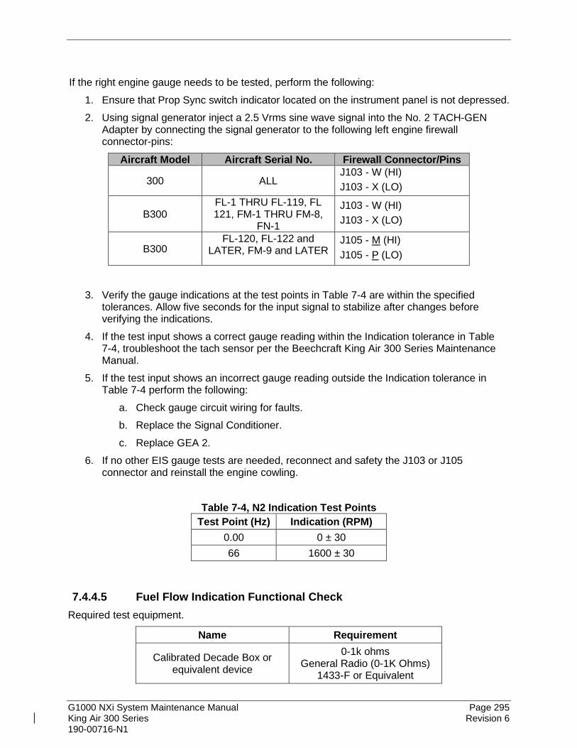
G1000 NXi System Maintenance Manual Page 295 King Air 300 Series Revision 6 190-00716-N1
If the right engine gauge needs to be tested, perform the following:
1. Ensure that Prop Sync switch indicator located on the instrument panel is not depressed. 2. Using signal generator inject a 2.5 Vrms sine wave signal into the No. 2 TACH-GEN
Adapter by connecting the signal generator to the following left engine firewall connector-pins:
Aircraft Model Aircraft Serial No. Firewall Connector/Pins
300 ALL J103 - W (HI) J103 - X (LO)
B300 FL-1 THRU FL-119, FL 121, FM-1 THRU FM-8,
FN-1
J103 - W (HI) J103 - X (LO)
B300 FL-120, FL-122 and
LATER, FM-9 and LATER J105 - M (HI) J105 - P (LO)
3. Verify the gauge indications at the test points in Table 7-4 are within the specified
tolerances. Allow five seconds for the input signal to stabilize after changes before verifying the indications.
4. If the test input shows a correct gauge reading within the Indication tolerance in Table 7-4, troubleshoot the tach sensor per the Beechcraft King Air 300 Series Maintenance Manual.
5. If the test input shows an incorrect gauge reading outside the Indication tolerance in Table 7-4 perform the following:
a. Check gauge circuit wiring for faults. b. Replace the Signal Conditioner. c. Replace GEA 2.
6. If no other EIS gauge tests are needed, reconnect and safety the J103 or J105 connector and reinstall the engine cowling.
Table 7-4, N2 Indication Test Points
Test Point (Hz) Indication (RPM) 0.00 0 ± 30 66 1600 ± 30
7.4.4.5 Fuel Flow Indication Functional Check Required test equipment.
Name Requirement
Calibrated Decade Box or equivalent device
0-1k ohms General Radio (0-1K Ohms)
1433-F or Equivalent

G1000 NXi System Maintenance Manual Page 296 King Air 300 Series Revision 6 190-00716-N1
Name Requirement
Calibrated Signal Generator 0-10Vdc / 0 – 1k Hz (Rigol DG1022 or Equivalent)
If the left engine gauge needs to be tested, perform the following:
1. Disconnect the J104 firewall connector. 2. Apply external power to aircraft and start the G1000 system in normal mode. 3. Inject a 1000 ± 10Ω resistance into the Signal Conditioner by connecting the Decade
box to left engine firewall connector-pins J104-H and J104-G. 4. Inject a 25mV P-P sine wave signal into the Signal Conditioner by connecting the Signal
Generator to the left engine firewall connector-pins J104-E (HI) and J104-O (LO). 5. If the test input shows a correct gauge reading within the Indication tolerance in Table
7-5, troubleshoot the fuel flow sensor per the Beechcraft King Air 300 Series Maintenance Manual.
6. If the test input shows an incorrect gauge reading outside the Indication tolerance in Table 7-5 perform the following:
a. Check gauge circuit wiring for faults. b. Replace the Signal Conditioner. c. Replace GEA 1.
7. If no other EIS gauge tests are needed, reconnect and safety the J104 connector and reinstall the engine cowling(s).
If the right engine gauge needs to be tested, perform the following:
1. Disconnect the J105 firewall connector. 2. Apply external power to aircraft and start the G1000 system in normal mode. 3. Inject a 1000 ± 10Ω resistance into the Signal Conditioner by connecting the Decade
box to left engine firewall connector-pins J105-H and J105-G. 4. Inject a 25mV P-P sine wave signal into the Signal Conditioner by connecting the Signal
Generator to the left engine firewall connector-pins J105-E (HI) and J105-O (LO). 5. If the test input shows a correct gauge reading within the Indication tolerance in Table
7-5, troubleshoot the fuel flow sensor per the Beechcraft King Air 300 Series Maintenance Manual.
6. If the test input shows an incorrect gauge reading outside the Indication tolerance in Table 7-5 perform the following:
a. Check gauge circuit wiring for faults. b. Replace the Signal Conditioner. c. Replace GEA 2.
7. If no other EIS gauge tests are needed, reconnect and safety the J105 connector and reinstall the engine cowling(s).

G1000 NXi System Maintenance Manual Page 297 King Air 300 Series Revision 6 190-00716-N1
Table 7-5, Fuel Flow Indication Test Points Test Point (Hz) Indication (PPH)
0 0 ± 2
140 100 ± 10 561 400 ± 10 841 600 ± 10
1122 800 ± 10
7.4.4.6 Oil Pressure Indication Functional Check Required test equipment:
Name Requirement
Calibrated DC Power Source 0-10 VDC (Fluke 525B, Fluke 725, or equivalent)
If the left engine gauge needs to be tested, perform the following:
1. Disconnect the J104 firewall connector. 2. Apply external power to aircraft and start the G1000 system in normal mode. 3. Inject a DC voltage into the GEA 1 by connecting the DC power source to the left engine
firewall connector-pins J104-A (LO) and J104-B (HI). 4. If the test input shows a correct gauge reading within the Indication tolerance in Table
7-6, troubleshoot the oil pressure sensor per the Beechcraft King Air 300 Series Maintenance Manual.
5. If the test input shows an incorrect gauge reading outside the Indication tolerance in Table 7-6 perform the following:
a. Check gauge circuit wiring for faults. b. Replace GEA 1.
6. Turn off the G1000 system and remove external power from the aircraft. 7. If no other EIS gauge tests are needed, reconnect and safety the J104 connector and
reinstall the engine cowling(s).
If the right engine gauge needs to be tested, perform the following: 1. Disconnect the J105 firewall connector. 2. Apply external power to aircraft and start the G1000 system in normal mode. 3. Inject a DC voltage into the GEA 1 by connecting the DC power source to the left engine
firewall connector-pins J105-A (LO) and J105-B (HI). 4. If the test input shows a correct gauge reading within the Indication tolerance in Table
7-6, troubleshoot the oil pressure sensor per the Beechcraft King Air 300 Series Maintenance Manual.

G1000 NXi System Maintenance Manual Page 298 King Air 300 Series Revision 6 190-00716-N1
5. If the test input shows an incorrect gauge reading outside the Indication tolerance in Table 7-6 perform the following:
a. Check gauge circuit wiring for faults. b. Replace GEA 2.
6. Turn off the G1000 system and remove external power from the aircraft. 7. If no other EIS gauge tests are needed, reconnect and safety the J105 connector and
reinstall the engine cowling(s). Table 7-6, Oil Pressure Test Points
Test Point (VDC) Indication (PSI) 1.75 70 ± 4 2.50 100 ± 4 3.75 150 ± 4
7.4.4.7 Oil Temperature Indication Functional Check Required test equipment:
Name Requirement
Calibrated Decade box or equivalent device
0-1k ohms General Radio (0-1K Ohms)
1433-F or Equivalent
If the left engine gauge needs to be tested, perform the following:
1. Disconnect the J104 firewall connector. 2. Apply external power to aircraft and start the G1000 system in normal mode. 3. Inject a resistance into GEA 1 by connecting the Decade box to the left engine firewall
connector-pins J104-W and J104-X. 4. If the test input shows a correct gauge reading within the Indication tolerance in Table
7-7, troubleshoot the oil temperature sensor per the Beechcraft King Air 300 Series Maintenance Manual.
5. If the test input shows an incorrect gauge reading outside the Indication tolerance in Table 7-7 perform the following:
a. Check gauge circuit wiring for faults. b. Replace GEA 1.
6. Turn off the G1000 system and remove external power from the aircraft. 7. If no other EIS gauge tests are needed, reconnect and safety the J104 connector and
reinstall the engine cowling(s). If the right engine gauge needs to be tested, perform the following:
1. Disconnect the J105 firewall connector. 2. Apply external power to aircraft and start the G1000 system in normal mode.
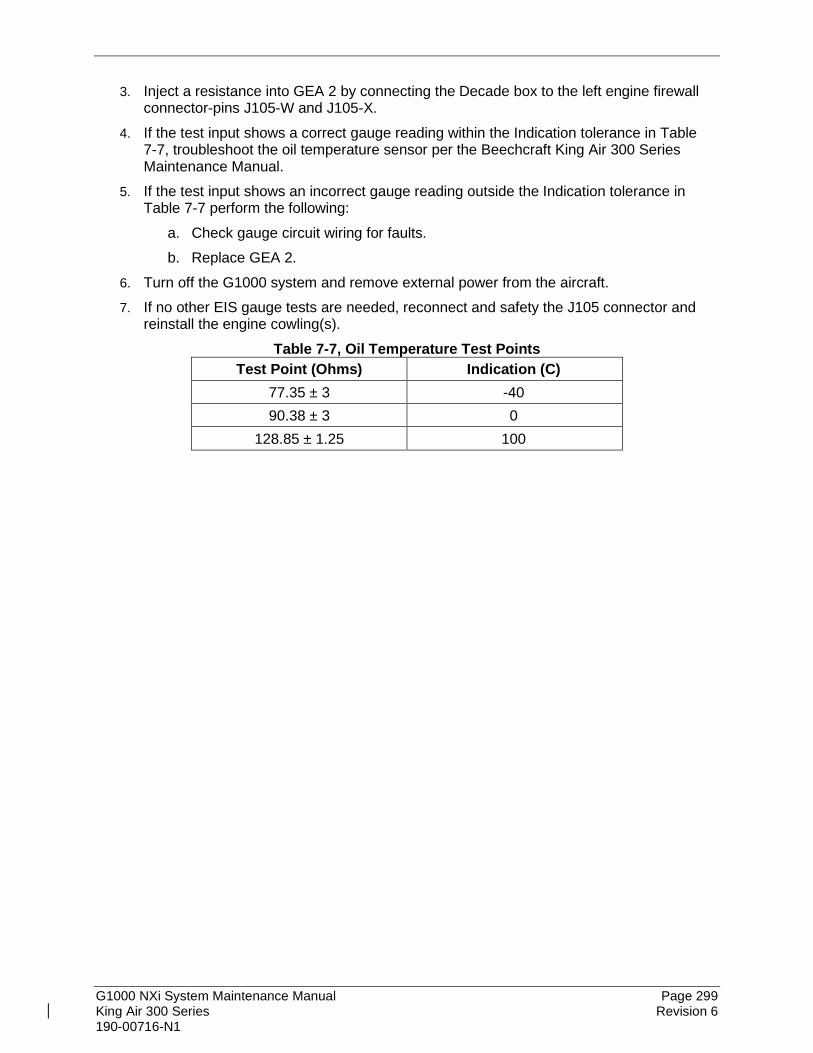
G1000 NXi System Maintenance Manual Page 299 King Air 300 Series Revision 6 190-00716-N1
3. Inject a resistance into GEA 2 by connecting the Decade box to the left engine firewall connector-pins J105-W and J105-X.
4. If the test input shows a correct gauge reading within the Indication tolerance in Table 7-7, troubleshoot the oil temperature sensor per the Beechcraft King Air 300 Series Maintenance Manual.
5. If the test input shows an incorrect gauge reading outside the Indication tolerance in Table 7-7 perform the following:
a. Check gauge circuit wiring for faults. b. Replace GEA 2.
6. Turn off the G1000 system and remove external power from the aircraft. 7. If no other EIS gauge tests are needed, reconnect and safety the J105 connector and
reinstall the engine cowling(s). Table 7-7, Oil Temperature Test Points
Test Point (Ohms) Indication (C) 77.35 ± 3 -40 90.38 ± 3 0
128.85 ± 1.25 100

G1000 NXi System Maintenance Manual Page 300 King Air 300 Series Revision 6 190-00716-N1
7.5 GTX 335R, GTX 345R, GTX 33( ), or GTX 3000 Transponder Original GTX is Reinstalled
No software or configuration loading is required if the removed GTX 335R, GTX 345R, GTX 33, or GTX 3000 is re-installed. This does not include units that were returned for repair as their software and configuration files are deleted during the repair testing process. Continue to GTX 335R, GTX 345R, GTX 33, or GTX 3000 Test Section 7.5.4. Original GTX Installed in Opposite Locations for Troubleshooting
No software loading is required if the original GTX #1 and GTX #2 are installed in opposite locations. Continue to Transponder Configuration Section 7.5.3. New, Repaired or Exchange GTX is Installed
If a new, repaired or exchange GTX 335R, GTX 345R, GTX 33( ), or GTX 3000 is installed, the correct software and configuration files must be loaded to the unit. See Section 7.5.1.
7.5.1 LRU Replacement Procedure GTX1 or GTX2 1. Open the MFD, PFD 1 (PRI), PFD 1 (SEC), and PFD 2 circuit breakers. 2. Apply power to the G1000 system by connecting external power to the aircraft to
energize the aircraft and avionics electrical busses. 3. Turn on Avionics electrical busses. 4. Power on PFD2, MFD, and PFD1 in configuration mode. 5. Using the PFD1, scroll to the LRU replacement page. 6. Activate the curser and select GTX1 or GTX2, whichever was replaced in the LRU
dropdown box. 7. Press the CHK All softkey. 8. Press the Load softkey. 9. Press ENT to acknowledge the process was complete. 10. Deactivate the curser. 11. Scroll to the Configuration Manager page. 12. Press the CNFM CFG softkey. 13. Select ok when prompted to “Confirm configuration as expected configuration” 14. Power cycle the system. Verify there are no red-Xs or system alerts. 15. If red-Xs or system alerts are present, troubleshoot as necessary using Section 5 or re-
load the system using the legacy method in Section 7.5.2. 16. If there are no red-Xs or system alerts, continue to Section 7.5.3.
7.5.2 Legacy Replacement Procedure GTX1 or GTX2 (Alternate Method) 1. Insert the software loader card in the top slot of PFD1. 2. Power on PFD2, MFD, and PFD1 in configuration mode. 3. Select NO when “Do you want to update system files” is displayed on the screen of
PFD1.

G1000 NXi System Maintenance Manual Page 301 King Air 300 Series Revision 6 190-00716-N1
4. Select the “SYSTEM UPLOAD” page using the small FMS knob on PFD1. 5. Activate cursor and rotate the small FMS knob to display the drop down menu. Rotate
the large FMS knob to highlight “06) Garmin Transponders” and press ENT key on PFD1.
6. Rotate the small FMS knob to display the drop down menu. Rotate the large FMS knob to highlight the installed transponder combination. Press ENT key on PFD1.
7. Press the CLR ALL softkey. 8. Use the large FMS knob to scroll to GTX 1 or GTX 2 whichever was replaced. 9. Highlight the software box and press the ENT key to check the box. 10. Highlight the Configuration box and press the ENT key to check the box. 11. Press “Load” softkey. 12. Monitor load progress. Verify software load completes without errors as indicated by the
following:
• Green “PASS” in the Configuration and Software columns for each item loaded.
• “Upload Complete………….”COMPLETE” in the summary box. 13. Acknowledge the prompt by pushing the ENT key. 14. Deactivate the curser. 15. Scroll to the Configuration Manager page. 16. Press the CNFM CFG softkey. 17. Select ok when prompted to “Confirm configuration as expected configuration” 18. Power cycle the system verify there are no red-Xs or system alerts. 19. If red-Xs or system alerts are present, troubleshoot as necessary using Section 5. 20. If there are no red-Xs or system alerts, continue to Section 7.5.3.
7.5.3 Transponder Configuration 1. If not applied, apply power to the G1000 system and put all displays into config mode. 2. On PFD1, select the AIRCRAFT CONFIGURATION page. 3. For GTX 33 unit replacement only, press the Set GTX # softkey for the unit replaced and
acknowledge the PFD1 prompt by pressing the ENT key. For GTX 3000 units only, press the SET GTX softkey and acknowledge the PFD1 prompt by pressing the ENT key. GTX 335R and 345R units automatically save the registration number, no action is needed for these units.
4. After completing transponder configuration, deactivate the cursor.

G1000 NXi System Maintenance Manual Page 302 King Air 300 Series Revision 6 190-00716-N1
Figure 7-5, Aircraft Registration
7.5.4 GTX 335R, GTX 345R, GTX 33( ), or GTX 3000 Test Operation of the GTX 335R, GTX 345R, GTX 33() or GTX 3000 Mode-S transponder is accomplished using PFD 1, PFD 2 or the MFD. Refer to G1000 King Air 300 Series Cockpit Reference Guide, listed in Table 1-1, for basic operation. The integrated transponder/altitude reporting system must be verified in accordance with Title 14 of the Code of Federal Regulations (14 CFR) §§ 91.411 and 91.413, every 24 calendar months, or any time the transponder is removed. This test requires the use of a Mode S ramp generator. Specific instructions for operating the ramp tester are contained in the applicable operator's manual. Refer to 14 CFR Part 43 Appendices E and F for testing criteria. Note that for GTX 33D or GTX 3000 units, the aircraft must be put on jacks to simulate an in-air condition in order to test the Mode S diversity transmission channel isolation. If no other service is to be performed, continue to the return-to-service checks in Section 9.
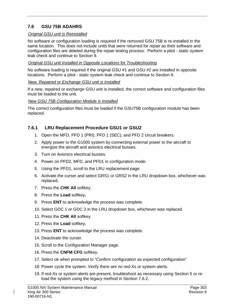
G1000 NXi System Maintenance Manual Page 303 King Air 300 Series Revision 6 190-00716-N1
7.6 GSU 75B ADAHRS Original GSU unit is Reinstalled
No software or configuration loading is required if the removed GSU 75B is re-installed in the same location. This does not include units that were returned for repair as their software and configuration files are deleted during the repair testing process. Perform a pitot - static system leak check and continue to Section 9. Original GSU unit Installed in Opposite Locations for Troubleshooting
No software loading is required if the original GSU #1 and GSU #2 are installed in opposite locations. Perform a pitot - static system leak check and continue to Section 9. New, Repaired or Exchange GSU unit is Installed
If a new, repaired or exchange GSU unit is installed, the correct software and configuration files must be loaded to the unit. New GSU 75B Configuration Module is Installed
The correct configuration files must be loaded if the GSU75B configuration module has been replaced.
7.6.1 LRU Replacement Procedure GSU1 or GSU2 1. Open the MFD, PFD 1 (PRI), PFD 1 (SEC), and PFD 2 circuit breakers. 2. Apply power to the G1000 system by connecting external power to the aircraft to
energize the aircraft and avionics electrical busses. 3. Turn on Avionics electrical busses. 4. Power on PFD2, MFD, and PFD1 in configuration mode. 5. Using the PFD1, scroll to the LRU replacement page. 6. Activate the curser and select GRS1 or GRS2 in the LRU dropdown box, whichever was
replaced. 7. Press the CHK All softkey. 8. Press the Load softkey. 9. Press ENT to acknowledge the process was complete. 10. Select GDC 1 or GDC 2 in the LRU dropdown box, whichever was replaced. 11. Press the CHK All softkey. 12. Press the Load softkey. 13. Press ENT to acknowledge the process was complete. 14. Deactivate the curser. 15. Scroll to the Configuration Manager page. 16. Press the CNFM CFG softkey. 17. Select ok when prompted to “Confirm configuration as expected configuration” 18. Power cycle the system. Verify there are no red-Xs or system alerts. 19. If red-Xs or system alerts are present, troubleshoot as necessary using Section 5 or re-
load the system using the legacy method in Section 7.6.2.

G1000 NXi System Maintenance Manual Page 304 King Air 300 Series Revision 6 190-00716-N1
20. If there are no red-Xs or system alerts, continue to Section 7.7.3 for the air data portion of the GSU and Section 7.10.5 for the AHRS portion of the GSU.
7.6.2 Legacy Replacement Procedure GSU1 or GSU2 (Alternate Method) 1. Insert the software loader card in the top slot of PFD1. 2. Power on PFD2, MFD, and PFD1 in configuration mode. 3. Select NO when “Do you want to update system files” is displayed on the screen of
PFD1. 4. Select the “SYSTEM UPLOAD” page using the small FMS knob on PFD1. 5. Activate cursor and rotate the small FMS knob to display the drop down menu. Rotate
the large FMS knob to highlight “04) AHRS – Air Data” and press ENT key on PFD1. 6. Rotate the small FMS knob to display the drop down menu. Rotate the large FMS knob
to highlight King Air- GSU 75B ADAHRS and GMU 44 Magnetometer. Press ENT key on PFD1.
7. Press the CLR ALL softkey. 8. Use the large FMS knob to scroll to GSU 1 or GSU 2 whichever was replaced. 9. Highlight the software box and press the ENT key to check the box. 10. Highlight the Configuration box and press the ENT key to check the box. 11. Press “Load” softkey. 12. Monitor load progress. Verify software load completes without errors as indicated by the
following:
• Green “PASS” in the Configuration and Software columns for each item loaded.
• “Upload Complete………….”COMPLETE” in the summary box. 13. Acknowledge the prompt by pushing the ENT key. 14. Deactivate the curser. 15. Scroll to the Configuration Manager page. 16. Press the CNFM CFG softkey. 17. Select ok when prompted to “Confirm configuration as expected configuration” 18. Power cycle the system. Verify there are no red-Xs or system alerts. 19. If red-Xs or system alerts are present, troubleshoot as necessary using Section 5. 21. If there are no red-Xs or system alerts, continue to Section 7.7.3 for the air data portion
of the GSU and Section 7.10.5 for the AHRS portion of the GSU.

G1000 NXi System Maintenance Manual Page 305 King Air 300 Series Revision 6 190-00716-N1
7.7 GDC 7400 Air Data Original GDC unit is Reinstalled
No software or configuration loading is required if the removed GDC 7400 is re-installed. This does not include units that were returned for repair as their software and configuration files are deleted during the repair testing process. Perform a pitot - static system leak check and continue to Section 9 if no other service is performed. Original GDC unit Installed in Opposite Locations for Troubleshooting
No software loading is required if the original GDC #1 and GDC #2 are installed in opposite locations. Perform Section 7.7.3 if no other service is performed. New, Repaired or Exchange GDC unit is Installed
If a new, repaired or exchange GDC unit is installed, the correct software and configuration files must be loaded to the unit.
7.7.1 LRU Replacement Procedure GDC 1 or GDC 2 1. Open the MFD, PFD 1 (PRI), PFD 1 (SEC), and PFD 2 circuit breakers. 2. Apply power to the G1000 system by connecting external power to the aircraft to
energize the aircraft and avionics electrical busses. 3. Turn on Avionics electrical busses. 4. Power on PFD2, MFD, and PFD1 in configuration mode. 5. Using the PFD1, scroll to the LRU replacement page. 6. Activate the curser and select GDC1 or GDC 2, whichever was replaced in the LRU
dropdown box. 7. Press the CHK All softkey. 8. Press the Load softkey. 9. Press ENT to acknowledge the process was complete. 10. Deactivate the curser. 11. Scroll to the Configuration Manager page. 12. Press the CNFM CFG softkey. 13. Select ok when prompted to “Confirm configuration as expected configuration” 14. Power cycle the system. Verify there are no red-Xs or system alerts. 15. If red-Xs or system alerts are present, troubleshoot as necessary using Section 5 or re-
load the system using the legacy method in Section 7.7.2. 16. If there are no red-Xs or system alerts, continue to Section 7.7.3.
7.7.2 Legacy Replacement Procedure GDC 1 or GDC 2 (Alternate Method) 1. Insert the software loader card in the top slot of PFD1. 2. Power on PFD2, MFD, and PFD1 in configuration mode. 3. Select NO when “Do you want to update system files” is displayed on the screen of
PFD1.

G1000 NXi System Maintenance Manual Page 306 King Air 300 Series Revision 6 190-00716-N1
4. Select the “SYSTEM UPLOAD” page using the small FMS knob on PFD1. 5. Activate cursor and rotate the small FMS knob to display the drop down menu. Rotate
the large FMS knob to highlight “04) AHRS – Air Data” and press ENT key on PFD1. 6. Rotate the small FMS knob to display the drop down menu. Rotate the large FMS knob
to highlight the installed GDC. Press ENT key on PFD1. 7. Press the CLR ALL softkey. 8. Use the large FMS knob to scroll to GDC 1 or GDC 2 whichever was replaced. 9. Highlight the software box and press the ENT key to check the box. 10. Highlight the Configuration box and press the ENT key to check the box. 11. Press “Load” softkey. 12. Monitor load progress. Verify software load completes without errors as indicated by the
following:
• Green “PASS” in the Configuration and Software columns for each item loaded.
• “Upload Complete………….”COMPLETE” in the summary box. 13. Acknowledge the prompt by pushing the ENT key. 14. Deactivate the curser. 15. Scroll to the Configuration Manager page. 16. Press the CNFM CFG softkey. 17. Select ok when prompted to “Confirm configuration as expected configuration” 18. Power cycle the system. Verify there are no red-Xs or system alerts. 19. If red-Xs or system alerts are present, troubleshoot as necessary using Section 5. 20. If there are no red-Xs or system alerts, continue to Section 7.7.3.
7.7.3 Air Data Test (GSU 75B or GDC 7400) The G1000 system must be maintained in accordance with the G1000 System Maintenance Manual listed in Table 1-2 and appropriate regulations. When the GDC unit is tested in accordance with 14 CFR Part 43, Appendix E, note the following exceptions:
• For paragraph (b)(1)(i) Scale Error, use Table 7-8 of this section instead of Appendix E, Table I
• Do not perform paragraph (b)(1)(iv) Friction
• Do not perform paragraph (b)(1)(vi) Barometric Scale Error The following Air Data Test is to be performed in addition to or in conjunction with any other regulated tests. This test must be performed on both pilot and copilot systems with a calibrated Air Data Test Set (ADTS) with a combined accuracy/repeatability specification of less than ±20 feet for the test altitude range.
1. Perform pitot static system leak check of each system as described in the King Air 300 Series Maintenance Manual, 34-00-00, with the following changes:
a. For the pitot leak check, set the air data test unit to an indicated airspeed of 200 knots with the static system vented to ambient pressure conditions (ground). Pitot leak rate is not to exceed 1 knot in 1 minute.

G1000 NXi System Maintenance Manual Page 307 King Air 300 Series Revision 6 190-00716-N1
b. For the static leak check, set the air data test set to 30,000 feet and an indicated airspeed of 120 knots. Static leak rate is not to exceed 300 feet in 1 minute.
2. Connect the pitot/static tester to the aircraft left and right pitot and static ports. Note that the standby altimeter and airspeed indicator are connected to the copilot side pitot and static lines.
3. Verify that the PFD1 altimeter baro setting is set to 29.92 in Hg (1013.25 mb). 4. Start PFD1 in configuration mode and navigate to the GRS page. The values for altitude
and airspeed are shown on the AHRS/AIR DATA INPUT table as B ALT and IAS for both AIR DATA 1 and AIR DATA 2.
5. Simulate the altitudes and airspeeds for each condition shown in Table 7-8. Wait for ADTS to report that target values have been achieved.
6. On Table 7-8, record the altitude (B ALT) displayed on PFD1 for AIR DATA 1 and AIR DATA 2 for each condition.
7. On Table 7-8, record the airspeed (IAS) displayed on PFD1 for AIR DATA 1 and AIR DATA 2 for each condition.
8. Verify that the indicated altitudes and airspeeds are within allowable tolerances. 9. File the results with the aircraft maintenance records.
If either the pilot or copilot air data system does not meet the tolerances specified, have maintenance checks performed on the air data system or the pitot/static system.

G1000 NXi System Maintenance Manual Page 308 King Air 300 Series Revision 6 190-00716-N1
Table 7-8, Air Data System Test Test Point Altitude (FT) Airspeed (KIAS)
Nominal Altitude
AIR DATA 1 AIR DATA 2 AIR DATA 1 AIR DATA 2
ALT AS
Tolerance Tolerance Tolerance Tolerance
Actual Actual Actual Actual 0
0 0 +/-20 +/-20 +/-2 +/-2
0
99 0 +/-20 +/-20 +/-2 +/-2
0
132 0 +/-20 +/-20 +/-2 +/-2
0 198 0
+/-20 +/-20 +/-2 +/-2
1000 50 1000
+/-20 +/-20 +/-2 +/-2
2000 50 2000
+/-25 +/-25 +/-2 +/-2
4000 80 4000
+/-25 +/-25 +/-2 +/-2
8000 80 8000
+/-30 +/-30 +/-2 +/-2
8000 260 8000
+/-30 +/-30 +/-2 +/-2
10000 120 10000
+/-30 +/-30 +/-2 +/-2
11000 120 11000
+/-35 +/-35 +/-2 +/-2
13000 150 13000
+/-40 +/-40 +/-2 +/-2
14000 150 14000
+/-40 +/-40 +/-2 +/-2
16000 180 16000
+/-45 +/-45 +/-2 +/-2
18000 210 18000
+/-45 +/-45 +/-2 +/-2
19000 138 18983
+/-47 +/-47 +/-2 +/-2
19000 162 18971
+/-47 +/-47 +/-2 +/-2
19000 185 18958
+/-47 +/-47 +/-2 +/-2
19000 209 18947
+/-47 +/-47 +/-2 +/-2
19000 221 18947
+/-47 +/-47 +/-2 +/-2
19000 233 18947
+/-47 +/-47 +/-2 +/-2

G1000 NXi System Maintenance Manual Page 309 King Air 300 Series Revision 6 190-00716-N1
Air Data System Test (Continued) Test Point Altitude (FT) Airspeed (KTS)
Nominal Altitude
AIR DATA 1 AIR DATA 2 AIR DATA 1 AIR DATA 2
ALT AS
Tolerance Tolerance Tolerance Tolerance Actual Actual Actual Actual
29000 111 28999
+/-72 +/-72 +/-2 +/-2
29000 130 28982
+/-72 +/-72 +/-2 +/-2
29000 150 28967
+/-72 +/-72 +/-2 +/-2
29000 169 28953
+/-72 +/-72 +/-2 +/-2
29000 178 28946
+/-72 +/-72 +/-2 +/-2
29000 188 28937
+/-72 +/-72 +/-2 +/-2
29000 196 28928
+/-72 +/-72 +/-2 +/-2
35000 97 35016
+/-87 +/-87 +/-2 +/-2
35000 114 34996
+/-87 +/-87 +/-2 +/-2
35000 130 34978
+/-87 +/-87 +/-2 +/-2
35000 147 34961
+/-87 +/-87 +/-2 +/-2
35000 156 34953
+/-87 +/-87 +/-2 +/-2
35000 164 34946
+/-87 +/-87 +/-2 +/-2
35000 171 34939
+/-87 +/-87 +/-2 +/-2
Aircraft S/N: _____________________ Date: __________________ Operator: __________________
ADTS
Make: _______________________
Model: _______________________
S/N: _______________________
Cal. Date: _____________________
ADAHRS1/ADC1
Model: __________
P/N: ___________________
S/N: ___________________
Cal. Date: ______________
ADAHRS2/ADC2
Model: __________
P/N: ____________________
S/N: ____________________
Cal. Date: ________________
Leak Check Static System at 30,000 ft, 120 kts (pass if <300 ft in 1 min)
Pilot: _____________ Feet/Min
Copilot: ___________ Feet/Min
Leak Check Pitot System at 200 kts (pass if <1 KIAS in 1 min)
Pilot: _____________ KIAS/Min
Copilot: ___________ KIAS/Min

G1000 NXi System Maintenance Manual Page 310 King Air 300 Series Revision 6 190-00716-N1
7.7.4 Static Port Vertical Speed (Rate of Climb) Test 1. Command ADTS to change the altitude at the rates shown in the table below. 2. Wait for ADTS to report that target rates have been achieved. 3. Verify that the Rate of Climb reported by the Vertical Speed field on PFD1 and PFD2 are
within the tolerances specified in Table 7-9. Table 7-9, Vertical Speed Table
Vertical Speed, feet/minute Allowed tolerance, ±feet/minute 2000 100 1000 50 500 45 200 45 0 N/A (No VS Display)
-200 45 -500 45
-1000 50 -2000 100
7.7.5 OAT Probe Check 1. Ensure on-side sensors for PFD1 and PFD2. 2. Ensure the outside air temperature (OAT) probes and a calibrated thermometer stabilize
at ambient temperature. 3. Verify that the OAT measurement shown on PFD1 and PFD2, in degrees Celsius,
indicate within 2 °C of the ambient temperature as measured by the calibrated thermometer.
If no other service is to be performed, continue to the return-to-service checks in Section 9.

G1000 NXi System Maintenance Manual Page 311 King Air 300 Series Revision 6 190-00716-N1
7.8 GRS 77 or 7800 AHRS and GMU 44 Magnetometer Original GRS is Reinstalled
If the original GRS is reinstalled, then no software loading is required. This does not include units that were returned for repair as their software and configuration files are deleted during the repair testing process. If the GRS rack was not removed or loosened, continue to the GRS/GMU Test Section 7.10.5. If the GRS rack was removed or loosened, continue to the GRS/GMU Calibration Procedures Section 7.10. Original GRS is installed in Opposite Location for Troubleshooting
If the original GRS #1 and GRS #2 are installed in opposite locations (GRS #1 and GRS #2 in opposite unit racks), no software loading is required. If the GRS rack(s) was not removed or loosened, continue to the GRS/GMU Test Section 7.10.5. If the GRS rack(s) was removed or loosened, continue to the GRS/GMU Calibration Procedures Section 7.10. New, Repaired or Exchange GRS is Installed
If a new, repaired or exchange GRS is installed, then software must be loaded. New GRS Configuration Module is Installed
If the GRS configuration module is replaced, no software loading is required. Continue to the GRS/GMU Calibration Procedures Section 7.10.
7.8.1 LRU Replacement Procedure GRS1 or GRS2 1. Open the MFD, PFD 1 (PRI), PFD 1 (SEC), and PFD 2 circuit breakers. 2. Apply power to the G1000 system by connecting external power to the aircraft to
energize the aircraft and avionics electrical busses. 3. Turn on Avionics electrical busses. 4. Power on PFD2, MFD, and PFD1 in configuration mode. 5. Using the PFD1, scroll to the LRU replacement page. 6. Activate the curser and select GRS1 or GRS2, whichever was replaced in the LRU
dropdown box. 7. Verify all boxes are checked. If they are not checked, press the CHK All softkey. 8. Press the Load softkey. 9. Press ENT to acknowledge the process was complete. 10. Deactivate the curser. 11. Scroll to the Configuration Manager page. 12. Press the CNFM CFG softkey. 13. Select ok when prompted to “Confirm configuration as expected configuration” 14. Power cycle the system. Verify there are no red-Xs or system alerts.
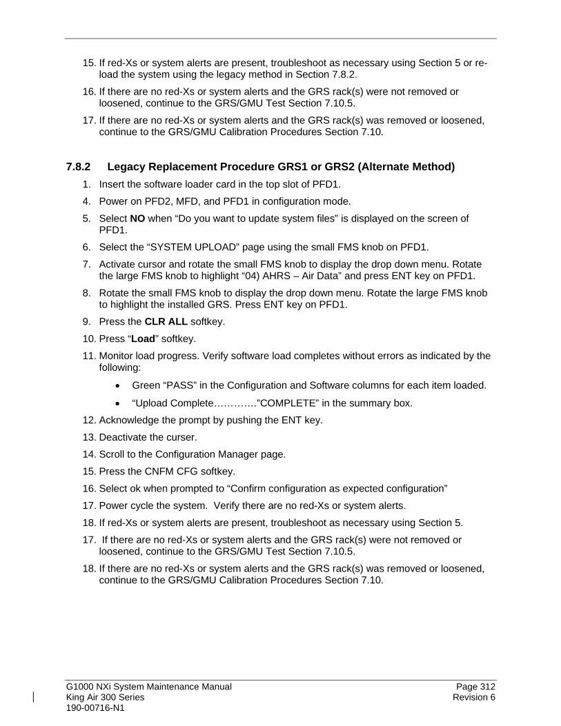
G1000 NXi System Maintenance Manual Page 312 King Air 300 Series Revision 6 190-00716-N1
15. If red-Xs or system alerts are present, troubleshoot as necessary using Section 5 or re-load the system using the legacy method in Section 7.8.2.
16. If there are no red-Xs or system alerts and the GRS rack(s) were not removed or loosened, continue to the GRS/GMU Test Section 7.10.5.
17. If there are no red-Xs or system alerts and the GRS rack(s) was removed or loosened, continue to the GRS/GMU Calibration Procedures Section 7.10.
7.8.2 Legacy Replacement Procedure GRS1 or GRS2 (Alternate Method) 1. Insert the software loader card in the top slot of PFD1. 4. Power on PFD2, MFD, and PFD1 in configuration mode. 5. Select NO when “Do you want to update system files” is displayed on the screen of
PFD1. 6. Select the “SYSTEM UPLOAD” page using the small FMS knob on PFD1. 7. Activate cursor and rotate the small FMS knob to display the drop down menu. Rotate
the large FMS knob to highlight “04) AHRS – Air Data” and press ENT key on PFD1. 8. Rotate the small FMS knob to display the drop down menu. Rotate the large FMS knob
to highlight the installed GRS. Press ENT key on PFD1. 9. Press the CLR ALL softkey. 10. Press “Load” softkey. 11. Monitor load progress. Verify software load completes without errors as indicated by the
following:
• Green “PASS” in the Configuration and Software columns for each item loaded.
• “Upload Complete………….”COMPLETE” in the summary box. 12. Acknowledge the prompt by pushing the ENT key. 13. Deactivate the curser. 14. Scroll to the Configuration Manager page. 15. Press the CNFM CFG softkey. 16. Select ok when prompted to “Confirm configuration as expected configuration” 17. Power cycle the system. Verify there are no red-Xs or system alerts. 18. If red-Xs or system alerts are present, troubleshoot as necessary using Section 5. 17. If there are no red-Xs or system alerts and the GRS rack(s) were not removed or
loosened, continue to the GRS/GMU Test Section 7.10.5. 18. If there are no red-Xs or system alerts and the GRS rack(s) was removed or loosened,
continue to the GRS/GMU Calibration Procedures Section 7.10.

G1000 NXi System Maintenance Manual Page 313 King Air 300 Series Revision 6 190-00716-N1
7.9 GMU 44 Magnetometer Original GMU 44 is Reinstalled
If the original GMU 44 is reinstalled, then no software loading is required. This does not include units that were returned for repair as their software and configuration files are deleted during the repair testing process. Continue to the GRS/GMU Test Section 7.10.5. Original GMU 44 is Installed in Opposite Location for Troubleshooting
If the original GMU #1 and GMU #2 are installed in opposite locations (GMU #1 and GMU #2 in opposite unit racks), no software loading is required. However, performing the Magnetometer Calibration Procedure is required. Continue to the GRS/GMU Magnetic Calibration Section 7.10.3. New, Repaired or Exchange GMU 44 is Installed
If a new, repaired or exchange GMU 44 is installed, then software must be loaded.
7.9.1 LRU Replacement Procedure GMU1 or GMU2 1. Open the MFD, PFD 1 (PRI), PFD 1 (SEC), and PFD 2 circuit breakers. 2. Apply power to the G1000 system by connecting external power to the aircraft to
energize the aircraft and avionics electrical busses. 3. Turn on Avionics electrical busses. 4. Power on PFD2, MFD, and PFD1 in configuration mode. 5. Using the PFD1, scroll to the LRU replacement page. 6. Activate the curser and select GMU1 or GMU2, whichever was replaced in the LRU
dropdown box. 7. Verify all boxes are checked. If they are not checked, press the CHK All softkey. 8. Press the Load softkey. 9. Press ENT to acknowledge the process was complete. 10. Deactivate the curser. 11. Scroll to the Configuration Manager page. 12. Press the CNFM CFG softkey. 13. Select ok when prompted to “Confirm configuration as expected configuration” 14. Power cycle the system. Verify there are no red-Xs or system alerts. 15. If red-Xs or system alerts are present, troubleshoot as necessary using Section 5 or re-
load the system using the legacy method in Section 7.9.2. 16. If there are no red-Xs or system alerts, continue to Section 7.10.
7.9.2 Legacy Replacement Procedure GMU1 or GMU2 (Alternate Method) 1. Insert the software loader card in the top slot of PFD1. 2. Power on PFD2, MFD, and PFD1 in configuration mode. 3. Select NO when “Do you want to update system files” is displayed on the screen of
PFD1.

G1000 NXi System Maintenance Manual Page 314 King Air 300 Series Revision 6 190-00716-N1
4. Select the “SYSTEM UPLOAD” page using the small FMS knob on PFD1. 5. Activate cursor and rotate the small FMS knob to display the drop down menu. Rotate
the large FMS knob to highlight “04) AHRS – Air Data” and press ENT key on PFD1. 6. Rotate the small FMS knob to display the drop down menu. Rotate the large FMS knob
to highlight the installed GRS. Press ENT key on PFD1. 7. Press the CLR ALL softkey. 8. Scroll to GMU1 or 2. 9. Highlight the Software box. 10. Press the ENT key. 11. Press “Load” softkey. 12. Monitor load progress. Verify software load completes without errors as indicated by the
following:
• Green “PASS” in the Configuration and Software columns for each item loaded.
• “Upload Complete………….”COMPLETE” in the summary box. 13. Acknowledge the prompt by pushing the ENT key. 14. Deactivate the curser. 15. Scroll to the Configuration Manager page. 16. Press the CNFM CFG softkey. 17. Select ok when prompted to “Confirm configuration as expected configuration” 18. Power cycle the system. Verify there are no red-Xs or system alerts. 19. If red-Xs or system alerts are present, troubleshoot as necessary using Section 5. 20. If there are no red-Xs or system alerts, continue to Section 7.10.

G1000 NXi System Maintenance Manual Page 315 King Air 300 Series Revision 6 190-00716-N1
7.10 GSU/GRS/GMU Calibration Procedures GSU/GRS/GMU Recalibration Criteria
The following calibration procedures are provided for the GRS and GMU 44:
• Pitch/Roll Offset: (Procedure A1, PROVIDED IN SECTION 7.10.1)
• Magnetometer Calibration: (Procedure B, PROVIDED IN SECTION 7.10.3)
• Engine Run-Up Vibration Test: (Procedure D, PROVIDED IN SECTION 7.10.4)
• Magnetometer Interference Test: (Procedure E, PROVIDED IN SECTION 5.17.4) Follow the steps given for each procedure on-screen at the GRS/GMU CALIBRATION page. Note that the CALIBRATE command cannot be selected and activated until the installer acknowledges all required steps have been carried out by pressing the ENT key on each step.
Table 7-10, Required GRS/GMU Calibrations
Condition
Calibrations Required Procedure A1:
GSU 75B, GRS 77, or GRS 7800 Pitch/Roll
Offset
Procedure B: GSU/GRS/GMU
Magnetic Calibration
Procedure D: Engine Run-up
Vibration Test
Either GMU 44 was removed and reinstalled. (no change in serial number)
None Required. Continue to GSU/GRS/GMU Test Section.
GMU 44 was replaced with new unit. (New serial number) X
GRS AHRS or GSU ADAHRS was removed and/or replaced. The mounting tray was NOT removed and the mounting tray bolts were NOT loosened.
None Required. Continue to GSU/GRS/GMU Test Section.
GRS AHRS or GSU ADAHRS was removed and/or replaced. The mounting tray WAS removed and/or mounting tray bolts WERE loosened.
X
X
X
GRS AHRS or GSU ADAHRS Configuration Module was replaced. X X X
7.10.1 Procedure A1: GSU 75B, GRS 77, or GRS 7800 Pitch/Roll Offset Calibration This procedure must be performed for both GSU/GRS units installed in the aircraft. This first procedure must be carried out with the engine off.
1. Level the aircraft to within ±0.25° of zero pitch and zero roll using a digital level. (Follow instructions in King Air 300 Series Maintenance Manual, listed in Table 1-1, for leveling)
2. Start PFD 1 in Configuration mode. 3. Go to the GRS Page Group and select the GRS/GMU Calibration page at the PFD. This
page is protected and the following softkey password must be entered at the PFD to continue:
• 9
• 10

G1000 NXi System Maintenance Manual Page 316 King Air 300 Series Revision 6 190-00716-N1
• 11
• 12 (Far Right softkey)
Figure 7-6, GRS/GMU Calibration, Pitch/Roll Offset
NOTE
On the calibration pages, “GRS” includes GRS and GSU units.
4. Ensure that the GRS 1 is selected in the SELECT GRS UNIT window on the PFD. 5. Activate the cursor and highlight the SELECT PROCEDURE window and select PITCH /
ROLL OFFSET. 6. Press the ENT key. 7. Use the cursor to highlight Step 1 in the BEFORE CALIBRATION window. 8. Follow the checklist items displayed on the PFD and press the ENT key as each step is
completed or confirmed. 9. When the CALIBRATE field is blinking, press the ENT button to begin the procedure. 10. After several seconds, a new checklist appears in the lower half of the PFD. Press the
ENT key as each step is confirmed. When the CONFIRM AIRCRAFT IS LEVEL field is blinking, press the ENT key to continue.
11. The result of the pitch/roll offset compensation is displayed on the PFD. If successful, the AHRS records the required pitch and roll offsets, informs the operator of a successful conclusion and returns to normal operation.
12. Press the ENT key on the PFD to conclude this procedure for GRS 1.

G1000 NXi System Maintenance Manual Page 317 King Air 300 Series Revision 6 190-00716-N1
13. Repeat steps 4 through 12 for GRS 2.
7.10.2 Compass Rose Evaluation of Magnetic Disturbances for Magnetometer Calibration Procedure (Optional)
NOTE The Magnetometer Calibration Procedure that follows in Section 7.10.3 (Calibration Procedure B) must be carried out at a site that is determined to be free of magnetic disturbances. If it is unsure whether the site is ‘clean’, the technician should verify that the site is ‘clean’ by following the guidance provided in Section 7.10.2. The technician may skip Section 7.10.2 if the site condition is acceptable. Typically, a compass rose is an acceptable location to perform the magnetometer calibration procedure. However, because not all compass roses are well maintained, even an existing compass rose should be regularly evaluated using the method described here to determine if it is free of magnetic disturbances. If evaluation of an existing compass rose indicates that magnetic disturbances are present, then an alternative location must be found to perform the Magnetometer Calibration Procedure.
A G1000-equipped airplane that has completed the pitch/roll offset compensation procedure (Procedure A-1, Section 7.10.1) can be used to evaluate a candidate site for magnetic disturbances and determine whether it is a suitable location to perform the magnetometer calibration procedure. The magnetometer calibration procedure itself contains the logic to simultaneously survey the location for magnetic cleanliness while it is computing the magnetometer calibration parameters. In order to evaluate a candidate site, the Magnetometer Calibration Procedure must be performed twice: once turning clockwise around the site, and once turning counter-clockwise. Both times, the procedure should be conducted as described in Section 7.10.3 of this document, with the exception of the direction of turns around the site.
NOTE Although Section 7.10.3 indicates that the Magnetometer Calibration Procedure should be performed by making a series of clockwise turns around the site, the procedure can also be performed by making counter-clockwise turns for the purpose of evaluating the site for magnetic disturbances.
If the PFD displays the “CALIBRATION SUCCESSFUL / SITE IS CLEAN” message upon completion of the Magnetometer Calibration Procedure in each clockwise and counter-clockwise direction, then the candidate site is sufficiently free of magnetic disturbances and is acceptable for performing the Magnetometer Calibration Procedure. It is important to obtain successful result in both the clockwise and counter-clockwise directions to ensure that the magnetometer sweeps over a large enough area at the candidate site. If the PFD displays either the “MAG FIELD AT SITE NOT UNIFORM” or “MAG FIELD AT SITE DIFFERS FROM IGRF MODEL” message upon completion of the Magnetometer Calibration

G1000 NXi System Maintenance Manual Page 318 King Air 300 Series Revision 6 190-00716-N1
Procedure in either of the two directions, then the site contains magnetic disturbances that are too large.
7.10.3 Procedure B: GSU 75, GRS 77, or GRS 7800 and GMU 44 Magnetic Calibration
NOTES Procedure A-1 (Section 7.10.1) must first be successfully accomplished before performing Procedure B, only for situations where the GSU/GRS was replaced with a new unit. On the calibration pages, “GRS” refers to whatever GRS or GSU unit is installed.
1. Start the aircraft engine following the procedures referenced in the appropriate King Air
AFM or AFMS as shown in the General Arrangement drawing, listed in Table 1-1. 2. After aircraft engine startup, taxi the aircraft to a properly calibrated compass rose.
3. At the compass rose, align the aircraft to a heading of magnetic north (±5°). CAUTION
Calibration Procedure B must be carried out on a compass rose in order to guarantee measurements free of environmental magnetic disturbances. Attempting to carry out this maneuver on a typical ramp area may not yield a successful calibration. The accuracy of the AHRS/ADAHRS cannot be guaranteed if this calibration is not performed on a magnetically clean compass rose or equivalent. If the compass rose condition is not known, it is recommended that the technician follow the guidance in Section 7.10.2.
NOTE This procedure provides instructions for calibrating both GRS AHRS or both GSU ADAHRS separately. It is acceptable to calibrate both GRS AHRS or both GSU ADAHRS simultaneously by putting both PFD 1 and PFD 2 in configuration mode and following the procedure below, using PFD 1 to calibrate GSU/GRS 1 and PFD 2 to calibrate GSU/GRS 2.
4. Restart PFD 1 in configuration mode. 5. Go to the GRS Page Group on the PFD. 6. Select the GRS/GMU Calibration page and enter the following softkey password:
• 9
• 10
• 11
• 12 (far right softkey) 7. Use the FMS small knob to highlight GRS/GSU for calibration and press the ENT key. 8. Using the FMS small knob, select MAGNETOMETER. Press the ENT button. 9. Use the cursor to highlight the first step in the BEFORE CALIBRATION window.

G1000 NXi System Maintenance Manual Page 319 King Air 300 Series Revision 6 190-00716-N1
10. Follow the checklist items displayed on the PFD and press the ENT key as each one is completed or confirmed. When the CALIBRATE field is blinking, press the ENT key to begin the procedure.
11. The PFD display advises the operator when to turn the aircraft, when to stop, and when to turn again.
12. Upon instruction to turn, taxi the aircraft in a right turn. After approximately 25° to 30° of turn from the last heading, the PFD display advises the operator to stop the aircraft.
NOTE Due to the difficulties in executing smooth, accurate turns the PFD may incorrectly interpret a station and instruct to “HOLD POSITION” prior to full completion of a 30° turn. If this scenario is encountered, it is best for the operator to ignore the “HOLD POSITION” command and instead use outside references to complete the approximate 30° turn. Instead of using the PFD instruction to turn as a real-time indication of when to turn, simply judge the 30° (±5°) turn increments of the aircraft by using the compass rose radials. Dwelling at these 30° increments for the time recommended by the PFD should result in successful calibration.
13. The PFD guides the operator to dwell at multiple headings around a complete circle.
NOTE Due to high winds or excessive airframe vibration, the operator may encounter a condition where the PFD restarts the 18-second countdown without full completion of the previous countdown. If this is encountered more than once for a given station, the operator should begin turning to the next station (approximately 30°). A minimum of 2 successful stations per quadrant is required, where a successful station is a full 18-second countdown followed by instruction to move. Ensure that at least 2 stations per quadrant are completed. Thus, it may sometimes be required to dwell at a station after a countdown restart. A maximum of 30 stations is allowed for the entire calibration procedure. If too many countdown restarts are encountered, the calibration will fail with the message, “TOO MANY STATIONS.”
14. Repeat the turn-and-stop process until the PFD advises that a successful calibration is
complete. The GRS AHRS/GSU ADAHRS then enters its normal operational mode. Press the ENT button on the PFD to conclude this procedure.
15. Repeat steps 7 through 14 for GSU/GRS 2.

G1000 NXi System Maintenance Manual Page 320 King Air 300 Series Revision 6 190-00716-N1
7.10.4 Procedure D: Engine Run-Up Vibration Procedure
NOTES On the calibration pages, “GRS” refers to whatever GRS or GSU unit is installed. Calibration Procedure D is performed in order to guarantee that the ADAHRS/AHRS mounting is sufficiently rigid and insensitive to vibration. This procedure must be performed for both GSU/GRS units installed in the aircraft. Calibration Procedures A1 and B (Sections 7.10.1 and 7.10.3 respectively) are not required prior to this procedure.
Figure 7-7, GRS/GMU Calibration, Engine Run-Up
1. Restart PFD 1 in configuration mode. 2. Use the FMS small knob to highlight GRS 1 for calibration and press the ENT key. The
SELECT PROCEDURE field is not blinking. 3. Initiate the AHRS engine run-up vibration test procedure by performing the following
steps: a) Select the ENGINE RUN-UP TEST procedure and press the ENT key. b) Follow the checklist items displayed on the PFD, and press the ENT key as each
one is completed or confirmed. When the CALIBRATE field is blinking, press the ENT key to begin the procedure.
4. The PFD display instructs the operator to gradually increase power from idle to full throttle and back to idle over a period of 2-4 minutes.
5. When the operator has completed the engine run-up and the engine is back to an idle setting, press the ENT key to indicate that the process is complete. When this is done, the TEST COMPLETE field stops blinking.

G1000 NXi System Maintenance Manual Page 321 King Air 300 Series Revision 6 190-00716-N1
6. The PFD informs the operator if the installation has passed or failed the vibration test. If the test fails, the specific measurements causing the failure are identified and associated numeric values are displayed on the PFD.
NOTE
Should a failure occur, the technician may perform the Engine Run-up test up to 3 times successively before corrective action must be taken. If the test does not pass after three attempts, then the installation should not be considered reliable until the source of the vibration problem is identified and remedied. In the event of repeated failure of the engine run-up test, record the values that are reported to be out of range for future reference. The following are potential causes for failure of the engine run-up test: a) Vibration motion of GSU/GRS and/or GMU44 caused by neighboring
equipment and/or supports. b) Mounting screws and other hardware for GSU/GRS and/or GMU44 not
firmly attached. c) GSU/GRS connector not firmly attached to unit. d) Cabling leading to GSU/GRS or GMU44 not firmly secured to supporting
structure. e) An engine / propeller that is significantly out of balance.
7. Press the ENT key on the PFD to conclude this procedure 8. Repeats steps 2 through 7 for GSU/GRS 2 then the aircraft can be taxied back and the
engine can be shut down for final testing. Continue to Section 7.10.5.
7.10.5 GSU/GRS/GMU Test Start the displays in normal mode. The ADAHRS/AHRS attitude and heading information displayed should become valid within 1 minute of power-up as shown in Figure 7-8 if at least one GPS receiver has a valid position. If GPS is unavailable, the ADAHRS/AHRS initialization may take up to 2 minutes.

G1000 NXi System Maintenance Manual Page 322 King Air 300 Series Revision 6 190-00716-N1
Figure 7-8, Normal Mode AHRS Check
If no other service is to be performed, continue to the return-to-service checks in Section 9.

G1000 NXi System Maintenance Manual Page 323 King Air 300 Series Revision 6 190-00716-N1
7.11 GDL 69A or GDL 69A SXM Data Link Original GDL 69A/69A SXM is Reinstalled No software or configuration loading is required if the removed GDL 69A is re-installed. This does not include units that were returned for repair as their software and configuration files are deleted during the repair testing process. Continue to the GDL 69A/69A SXM Test Section 7.11.3. New, Repaired or Exchange GDL 69A/69A SXM is Installed If a new, repaired or exchange GDL 69A/69A SXM is installed, the correct software and configuration files must be loaded to the unit, then the SiriusXM Satellite Radio subscription must be reactivated. See the SiriusXM Activation Instructions listed in Table 1-2.
7.11.1 LRU Replacement Procedure 1. Open the MFD, PFD 1 (PRI), PFD 1 (SEC), and PFD 2 circuit breakers. 2. Apply power to the G1000 system by connecting external power to the aircraft to
energize the aircraft and avionics electrical busses. 3. Turn on Avionics electrical busses. 4. Power on PFD2, MFD, and PFD1 in configuration mode. 5. Using the PFD1, scroll to the LRU replacement page. 6. Activate the curser and select GDL69 in the LRU dropdown box. 7. Press the CHK All softkey. 8. Press the Load softkey. 9. Press ENT to acknowledge the process was complete. 10. Deactivate the curser. 11. Scroll to the Configuration Manager page. 12. Press the CNFM CFG softkey. 13. Select ok when prompted to “Confirm configuration as expected configuration” 14. Power cycle the system. Verify there are no red-Xs or system alerts. 15. If red-Xs or system alerts are present, troubleshoot as necessary using Section 5 or re-
load the system using the legacy method in Section 7.11.2. 16. If there are no red-Xs or system alerts, continue to Section 7.11.3.
7.11.2 Legacy Replacement Procedure GDL69 (Alternate Method) 1. Insert the software loader card in the top slot of PFD1. 2. Power on PFD2, MFD, and PFD1 in configuration mode. 3. Select NO when “Do you want to update system files” is displayed on the screen of
PFD1. 4. Select the “SYSTEM UPLOAD” page using the small FMS knob on PFD1. 5. Activate cursor and rotate the small FMS knob to display the drop down menu. Rotate
the large FMS knob to highlight “Connext – SXM” and press ENT key on PFD1.

G1000 NXi System Maintenance Manual Page 324 King Air 300 Series Revision 6 190-00716-N1
6. Rotate the small FMS knob to display the drop down menu. Rotate the large FMS knob to highlight the installed GDL69. Press ENT key on PFD1.
7. Press the CLR ALL softkey. 8. Press the Load softkey. 9. Monitor load progress. Verify software load completes without errors as indicated by the
following:
• Green “PASS” in the Configuration and Software columns for each item loaded.
• “Upload Complete………….COMPLETE” in the summary box.
NOTE If the software load fails, cycle power to the GDL 69A only and confirm that the software part number and version are updated in the DATA window on the MFD. Then, press ENT button on the PFD to check the GDL 69A SXM SOFTWARE and CONFIGURATION check boxes and press LOAD softkey again to resume the software update.
10. Press ENT key on PFD1 to acknowledge upload complete. 11. Deactivate cursor. 12. Scroll to the Configuration Manager page. 13. Press the CNFM CFG softkey. 14. Select ok when prompted to “Confirm configuration as expected configuration” 15. Power cycle the system. Verify there are no red-Xs or system alerts. 16. If red-Xs or system alerts are present, troubleshoot as necessary using Section 5. 17. If there are no red-Xs or system alerts, continue to Section 7.11.3.
7.11.3 GDL 69A Test The aircraft must be outside and clear of any obstructions in order to receive XM service. If a SiriusXM Satellite Radio subscription has already been activated for the GDL 69A/69A SXM, then power up the G1000 and go to the Aux – Information page and verify that the GDL 69A/69A SXM is working properly. Refer to the Cockpit Reference Guide, listed in Table 1-2, for details on Sirius XM Radio weather and music operation. If the GDL 69A/69A SXM is replaced (new unit), the owner must re-activate the subscription, using the new GDL 69A/69A SXM’s Radio ID number(s). Refer to the GDL 69A/69A SXM Satellite Radio Activation Instructions, listed in Table 1-2, for details on the activation process. Ensure there are no MANIFEST errors shown on the PFD for the GDL 69A/69A SXM. If no other service is to be performed, continue to the return-to-service checks in Section 9.

G1000 NXi System Maintenance Manual Page 325 King Air 300 Series Revision 6 190-00716-N1
NOTE
This section verifies correct installation in the aircraft. It does not activate the GDL 69A data link SiriusXM satellite radio. If the satellite radio is activated, the channel list will contain more channels than the three that are shown for a radio that has not been activated.
Complete instructions for activating the SirusXM satellite radio can be found in document 190-00355-04 “GDL 69 Series SiriusXM® Satellite Radio Activation Instructions”.
On GMA 1 and GMA 2, press the MUSIC keys to turn on the music inputs. This enables the music to be heard in the headsets. Music will not play over the cockpit speakers.
Select the AUX – XM Radio page on the MFD. Press the Radio softkey. Verify that you can increment and decrement the channels (the white arrow to the left of
the channel list indicates the currently selected channel). Select channel 1 when complete.
Verify that you can increase and decrease the XM radio volume using the on-side GMA. Set the volume to the mid position when done.
Plug a set of headphones into each passenger station (if installed) and verify that you can hear the XM radio playing in both channels. The volume level may be adjusted to a comfortable level at this point.
Plug a set of headphones into the pilot and co-pilot stations and verify that you can hear the XM radio playing in both channels.
Select the Map - Navigation Map on the MFD. Press the MENU button on the GMC, then ensure Map Settings is highlighted in the
Page Menu Options window and press the ENT button. Ensure Weather is selected in the Map Settings Group window, then use the FMS knob on the GMC to scroll to NEXRAD Data. Use the FMS knob to select NEXRAD Data On, then ensure the range setting is set to 1000NM. Press the FMS knob on the GMC to close the Map Settings window. Press the Map Opt softkey on the MFD and ensure that the NEXRAD softkey is illuminated green. Ensure that the system displays NEXRAD weather data on the navigation map (if weather is available). Use the FMS knob on the GMC to scroll to any other page in the Map group, then scroll back to the Map - Navigation Map and ensure that the NEXRAD softkey is still illuminated green and NEXRAD weather data is still being displayed on the map. Press the NEXRAD softkey on the Map - Navigation Map to turn NEXRAD off. Press the NEXRAD softkey on the Map - Navigation Map again to turn NEXRAD on. Ensure that the NEXRAD softkey is illuminated green.

G1000 NXi System Maintenance Manual Page 326 King Air 300 Series Revision 6 190-00716-N1
7.12 GSA 80 Servos Original Servo(s) Reinstalled
No software loading is required if the removed servo(s) is re-installed. This does not include units that were returned for repair as their software and configuration files are deleted during the repair testing process. Continue to the return-to-service checks in Section 9. New, Repaired or Exchange Servo(s) Installed
If a new, repaired or exchange servo is installed, the correct software files and certification gains must be loaded to the unit.
7.12.1 LRU Replacement Procedure GSA80 Servos 1. Open the MFD, PFD 1 (PRI), PFD 1 (SEC), and PFD 2 circuit breakers. 2. Apply power to the G1000 system by connecting external power to the aircraft to
energize the aircraft and avionics electrical busses. 3. Turn on Avionics electrical busses. 4. Power on PFD2, MFD, and PFD1 in configuration mode. 5. Using the PFD1, scroll to the LRU replacement page. 6. Activate the curser and select the installed GSA CTRL in the LRU dropdown box. 7. Press the CHK All softkey. 8. Press the Load softkey. 9. Press ENT to acknowledge the process was complete. 10. Select the installed GSA MON in the LRU dropdown box. 11. Press the CHK All softkey. 12. Press the Load softkey. 13. Press ENT to acknowledge the process was complete. 14. Deactivate the curser. 15. Scroll to the Configuration Manager page. 16. Press the CNFM CFG softkey. 17. Select ok when prompted to “Confirm configuration as expected configuration” 18. Power cycle the system. Verify there are no red-Xs or system alerts. 19. If red-Xs or system alerts are present, troubleshoot as necessary using Section 5 or re-
load the system using the legacy method in Section 7.12.2. 20. If there are no red-Xs or system alerts, continue to return to service checks in Section 9.

G1000 NXi System Maintenance Manual Page 327 King Air 300 Series Revision 6 190-00716-N1
7.12.2 Legacy Replacement Procedure GSA80 Servos (Alternate Method) 1. Insert the software loader card in the top slot of PFD1. 2. Power on PFD2, MFD, and PFD1 in configuration mode. 3. Select NO when “Do you want to update system files” is displayed on the screen of
PFD1. 4. Select the “SYSTEM UPLOAD” page using the small FMS knob on PFD1. 5. Activate cursor and rotate the small FMS knob to display the drop down menu. Rotate
the large FMS knob to highlight “05) Autopilot” and press ENT key on PFD1. 6. Rotate the small FMS knob to display the drop down menu. Rotate the large FMS knob
highlight the installed autopilot configuration. Press ENT key on PFD1. 7. Press the CLR ALL key. 8. Scroll to highlight the installed servo. 9. Highlight the software box and press the ENT key to check the box. 10. Scroll to highlight the installed servo cert line. 11. Highlight the software box and press the ENT key to check the box. 12. Press the Load softkey. 13. Monitor load progress. Verify software load completes without errors as indicated by the
following:
• Green “PASS” in the Configuration and Software columns for each item loaded.
• “Upload Complete………….COMPLETE” in the summary box. 14. Press ENT key on PFD1 to acknowledge upload complete. 15. Deactivate cursor. 16. Scroll to the Configuration Manager page. 17. Press the CNFM CFG softkey. 18. Select ok when prompted to “Confirm configuration as expected configuration” 19. Power cycle the system. Verify there are no red-Xs or system alerts. 20. If red-Xs or system alerts are present, troubleshoot as necessary using Section 5. 21. If there are no red-Xs or system alerts, continue to return to service checks in Section 9.

G1000 NXi System Maintenance Manual Page 328 King Air 300 Series Revision 6 190-00716-N1
7.13 GCU 477 FMS Controller Original GCU 477 Reinstalled
No software or configuration loading is required if the removed GCU 477 is re-installed. This does not include units that were returned for repair as their software and configuration files are deleted during the repair testing process. Continue to the GCU 477 Test Section 7.13.3. New, Repaired or Exchange GCU 477 Installed
If a new, repaired or exchange GCU 477 is installed, the correct software and configuration files must be loaded to the unit. See Section 3.6 and then continue to the GCU 477 Test Section 7.13.3.
7.13.1 LRU Replacement Procedure GCU 477 1. Open the MFD, PFD 1 (PRI), PFD 1 (SEC), and PFD 2 circuit breakers. 2. Apply power to the G1000 system by connecting external power to the aircraft to
energize the aircraft and avionics electrical busses. 3. Turn on Avionics electrical busses. 4. Power on PFD2, MFD, and PFD1 in configuration mode. 5. Using the PFD1, scroll to the LRU replacement page. 6. Activate the curser and select the installed servo CTL in the LRU dropdown box. 7. Press the Load softkey. 8. Press ENT to acknowledge the process was complete. 9. Select the installed servo MON in the LRU dropdown box. 10. Press the Load softkey. 11. Press ENT to acknowledge the process was complete. 12. Deactivate the curser. 13. Scroll to the Configuration Manager page. 14. Press the CNFM CFG softkey. 15. Select ok when prompted to “Confirm configuration as expected configuration” 16. Power cycle the system. Verify there are no red-Xs or system alerts. 17. If red-Xs or system alerts are present, troubleshoot as necessary using Section 5 or re-
load the system using the legacy method in Section 7.13.2. 18. If there are no red-Xs or system alerts, continue to Section 7.13.3.
7.13.2 Legacy Replacement Procedure GCU 477 (Alternate Method) 1. Insert the software loader card in the top slot of PFD1. 2. Power on PFD2, MFD, and PFD1 in configuration mode. 3. Select NO when “Do you want to update system files” is displayed on the screen of
PFD1. 4. Select the “SYSTEM UPLOAD” page using the small FMS knob on PFD1.
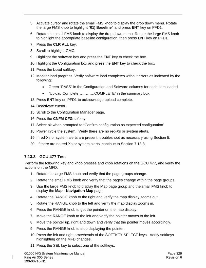
G1000 NXi System Maintenance Manual Page 329 King Air 300 Series Revision 6 190-00716-N1
5. Activate cursor and rotate the small FMS knob to display the drop down menu. Rotate the large FMS knob to highlight “01) Baseline” and press ENT key on PFD1.
6. Rotate the small FMS knob to display the drop down menu. Rotate the large FMS knob to highlight the appropriate baseline configuration, then press ENT key on PFD1.
7. Press the CLR ALL key. 8. Scroll to highlight GMC. 9. Highlight the software box and press the ENT key to check the box. 10. Highlight the Configuration box and press the ENT key to check the box. 11. Press the Load softkey. 12. Monitor load progress. Verify software load completes without errors as indicated by the
following:
• Green “PASS” in the Configuration and Software columns for each item loaded.
• “Upload Complete………….COMPLETE” in the summary box. 13. Press ENT key on PFD1 to acknowledge upload complete. 14. Deactivate cursor. 15. Scroll to the Configuration Manager page. 16. Press the CNFM CFG softkey. 17. Select ok when prompted to “Confirm configuration as expected configuration” 18. Power cycle the system. Verify there are no red-Xs or system alerts. 19. If red-Xs or system alerts are present, troubleshoot as necessary using Section 5. 20. If there are no red-Xs or system alerts, continue to Section 7.13.3.
7.13.3 GCU 477 Test Perform the following key and knob presses and knob rotations on the GCU 477, and verify the actions on the MFD.
1. Rotate the large FMS knob and verify that the page groups change. 2. Rotate the small FMS knob and verify that the pages change within the page groups. 3. Use the large FMS knob to display the Map page group and the small FMS knob to
display the Map - Navigation Map page. 4. Rotate the RANGE knob to the right and verify the map display zooms out. 5. Rotate the RANGE knob to the left and verify the map display zooms in. 6. Press the RANGE knob to get the pointer on the map display. 7. Move the RANGE knob to the left and verify the pointer moves to the left. 8. Move the pointer up, right and down and verify that the pointer moves accordingly. 9. Press the RANGE knob to stop displaying the pointer. 10. Press the left and right arrowheads of the SOFTKEY SELECT keys. Verify softkeys
highlighting on the MFD changes. 11. Press the SEL key to select one of the softkeys.
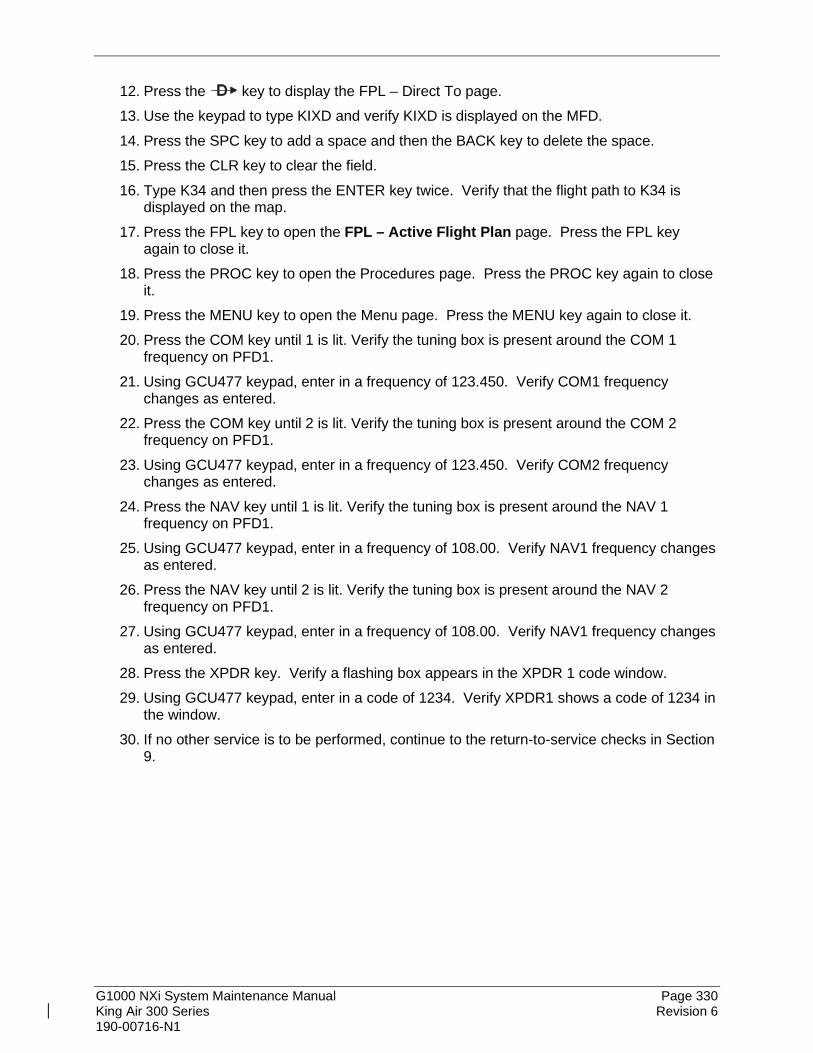
G1000 NXi System Maintenance Manual Page 330 King Air 300 Series Revision 6 190-00716-N1
12. Press the key to display the FPL – Direct To page. 13. Use the keypad to type KIXD and verify KIXD is displayed on the MFD. 14. Press the SPC key to add a space and then the BACK key to delete the space. 15. Press the CLR key to clear the field. 16. Type K34 and then press the ENTER key twice. Verify that the flight path to K34 is
displayed on the map. 17. Press the FPL key to open the FPL – Active Flight Plan page. Press the FPL key
again to close it. 18. Press the PROC key to open the Procedures page. Press the PROC key again to close
it. 19. Press the MENU key to open the Menu page. Press the MENU key again to close it. 20. Press the COM key until 1 is lit. Verify the tuning box is present around the COM 1
frequency on PFD1. 21. Using GCU477 keypad, enter in a frequency of 123.450. Verify COM1 frequency
changes as entered. 22. Press the COM key until 2 is lit. Verify the tuning box is present around the COM 2
frequency on PFD1. 23. Using GCU477 keypad, enter in a frequency of 123.450. Verify COM2 frequency
changes as entered. 24. Press the NAV key until 1 is lit. Verify the tuning box is present around the NAV 1
frequency on PFD1. 25. Using GCU477 keypad, enter in a frequency of 108.00. Verify NAV1 frequency changes
as entered. 26. Press the NAV key until 2 is lit. Verify the tuning box is present around the NAV 2
frequency on PFD1. 27. Using GCU477 keypad, enter in a frequency of 108.00. Verify NAV1 frequency changes
as entered. 28. Press the XPDR key. Verify a flashing box appears in the XPDR 1 code window. 29. Using GCU477 keypad, enter in a code of 1234. Verify XPDR1 shows a code of 1234 in
the window. 30. If no other service is to be performed, continue to the return-to-service checks in Section
9.

G1000 NXi System Maintenance Manual Page 331 King Air 300 Series Revision 6 190-00716-N1
7.14 GMC 710 AFCS Controller Original GMC 710 Reinstalled
No software or configuration loading is required if the removed GMC 710 is re-installed. This does not include units that were returned for repair as their software and configuration files are deleted during the repair testing process. Continue to the GMC 710 Test Section 7.14.3. New, Repaired or Exchange GMC 710 Installed
If a new, repaired or exchange GMC 710 is installed, the correct software and configuration files must be loaded to the unit. See Section 3.6 and then continue to the GMC 710 Test Section 7.14.3.
7.14.1 LRU Replacement Procedure GMC 710 1. Open the MFD, PFD 1 (PRI), PFD 1 (SEC), and PFD 2 circuit breakers. 2. Apply power to the G1000 system by connecting external power to the aircraft to
energize the aircraft and avionics electrical busses. 3. Turn on Avionics electrical busses. 4. Power on PFD2, MFD, and PFD1 in configuration mode. 5. Using the PFD1, scroll to the LRU replacement page. 6. Activate the curser and select GMC1 in the LRU dropdown box. 7. Press the Load softkey. 8. Press ENT to acknowledge the process was complete. 9. Deactivate the curser. 10. Scroll to the Configuration Manager page. 11. Press the CNFM CFG softkey. 12. Select ok when prompted to “Confirm configuration as expected configuration” 13. Power cycle the system. Verify there are no red-Xs or system alerts. 14. If red-Xs or system alerts are present, troubleshoot as necessary using Section 5 or re-
load the system using the legacy method in Section 7.14.2 15. If there are no red-Xs or system alerts, continue to Section 7.14.3.
7.14.2 Legacy Replacement Procedure GMC 710 (Alternate Method) 1. Insert the software loader card in the top slot of PFD1. 2. Power on PFD2, MFD, and PFD1 in configuration mode. 3. Select NO when “Do you want to update system files” is displayed on the screen of
PFD1. 4. Select the “SYSTEM UPLOAD” page using the small FMS knob on PFD1. 5. Activate cursor and rotate the small FMS knob to display the drop down menu. Rotate
the large FMS knob to highlight “01) Baseline” and press ENT key on PFD1. 6. Rotate the small FMS knob to display the drop down menu. Rotate the large FMS knob
to highlight the appropriate baseline configuration, then press ENT key on PFD1.

G1000 NXi System Maintenance Manual Page 332 King Air 300 Series Revision 6 190-00716-N1
7. Press the CLR ALL key. 8. Scroll to highlight GMC. 9. Highlight the software box and press the ENT key to check the box. 10. Highlight the Configuration box and press the ENT key to check the box. 11. Press the Load softkey. 12. Monitor load progress. Verify software load completes without errors as indicated by the
following:
• Green “PASS” in the Configuration and Software columns for each item loaded.
• “Upload Complete………….COMPLETE” in the summary box. 13. Press ENT key on PFD1 to acknowledge upload complete. 14. Deactivate cursor. 15. Scroll to the Configuration Manager page. 16. Press the CNFM CFG softkey. 17. Select ok when prompted to “Confirm configuration as expected configuration” 18. Power cycle the system. Verify there are no red-Xs or system alerts. 19. If red-Xs or system alerts are present, troubleshoot as necessary using Section 5 20. If there are no red-Xs or system alerts, continue to Section 7.14.3.
7.14.3 GMC 710 Functional check Perform a basic operational check on the GMC 710. The following knob, wheel and key presses and rotations are to be performed on the GMC 710.
1. Ensure the G1000 is operating in normal mode and the autopilot is operational. 2. Press the FD key a few times; verify the Flight Director display on PFD1 toggles on and
off. Leave the flight director displayed. 3. Press the XFR key and verify the white-illuminated arrowhead points in the opposite
direction. Verify the green arrow displayed at the top of PFD 1 also points in the same direction.
4. Rotate the ALT SEL knob and verify the altitude bug, displayed on PFD 1 altitude tape, moves.
5. Rotate the UP/DN wheel and verify the flight director moves in the vertical direction. 6. Press the HDG key and verify the white illumination appears next to the key. Rotate the
HDG knob and verify the heading bug, displayed on PFD 1 compass card, moves and the flight director follows.
7. Press the HDG knob and verify the heading bug centers. 8. Press the YD key and verify the white illumination appears next to the key. 9. Press the VS key and verify the white illumination appears next to the key. 10. Press the FLC key and verify the white illumination appears next to the key. 11. If no other service is to be performed, continue to the return-to-service checks in Section
9.

G1000 NXi System Maintenance Manual Page 333 King Air 300 Series Revision 6 190-00716-N1
7.15 GWX 68, GWX 70, or GWX 75 Weather Radar Original GWX Reinstalled
No software or configuration loading is required if the removed GWX is re-installed. This does not include units that were returned for repair as their software and configuration files are deleted during the repair testing process. Continue to the GWX Test Section 7.15.3. New, Repaired or Exchange GWX Installed
If a new, repaired or exchange GWX is installed, the correct software and configuration files must be loaded to the unit. See Section 3.6 and then continue to the GWX Test Section 7.15.3.
7.15.1 LRU Replacement Procedure GWX LRU Replacement feature is not available for the GWX. Continue to Section 7.15.2.
7.15.2 Legacy Replacement Procedure GWX (Alternate Method) 1. Insert the software loader card in the top slot of PFD1. 2. Power on PFD2, MFD, and PFD1 in configuration mode. 3. Select NO when “Do you want to update system files” is displayed on the screen of
PFD1. 4. Select the “SYSTEM UPLOAD” page using the small FMS knob on PFD1. 5. Activate cursor and rotate the small FMS knob to display the drop down menu. Rotate
the large FMS knob to highlight “08) Radar” and press ENT key on PFD1. 6. Rotate the small FMS knob to display the drop down menu. Rotate the large FMS knob
to highlight the installed radar. Press ENT key on PFD1. 7. Press the CHK All softkey. 8. Press the Load softkey. 9. Monitor load progress. Verify software load completes without errors as indicated by the
following:
• Green “PASS” in the Configuration and Software columns for each item loaded.
• “Upload Complete………….COMPLETE” in the summary box. 10. Press ENT key on PFD1 to acknowledge upload complete. 11. Deactivate cursor. 12. Scroll to the Configuration Manager page. 13. Press the CNFM CFG softkey. 14. Select ok when prompted to “Confirm configuration as expected configuration” 15. Power cycle the system. Verify there are no red-Xs or system alerts. 16. If red-Xs or system alerts are present, troubleshoot as necessary using Section 5. 17. If there are no red-Xs or system alerts, continue to Section 7.15.3.

G1000 NXi System Maintenance Manual Page 334 King Air 300 Series Revision 6 190-00716-N1
7.15.3 GWX Functional Check Operation of the GWX Weather Radar is accomplished using the MFD/GCU 477. Refer to G1000 King Air 300 Series Cockpit Reference Guide, listed in Table 1-2, for basic operation.
NOTE Before energizing the equipment, be sure microwave radiation safety precautions including both fuel and personnel safety considerations have been observed. These include clearing all personnel to an area beyond the maximum permissible exposure level (MPEL) boundary, approximately 10 feet.
1. On the GCU, turn the large FMS knob to select the Map Page Group then turn the small
FMS knob to select the Map – Weather Radar page. 2. Select the Mode softkey. 3. Select the Standby softkey to initiate the one-minute warm-up period. Verify the radar
enters the standby mode after the warm-up is complete. 4. Select the Mode softkey. 5. Select the Weather softkey. After reading the CAUTION statement, turn the large FMS
knob to select YES. Press the GCU ENT key. 6. Select the STAB softkey to activate or deactivate antenna stabilization. Verify the current
stabilization condition is shown in the upper right of the weather radar display. 7. Select the Back softkey. 8. Select the Vertical softkey. 9. Select the Tilt softkey to activate the cursor in the Tilt field. 10. On the GCU, turn the small FMS knob to select the desired antenna tilt angle. Press the
GCU ENT key. Press the GCU FMS knob to remove the cursor. 11. Select the Gain softkey to activate the cursor in the Gain field. 12. On the GCU, turn the small FMS knob to adjust the gain for the desirable level. Verify
the gain setting is visible in the gain field as a movable horizontal bar in a flashing box and the line pointer is a reference depicting the calibrated position. Press the FMS knob to remove the cursor.
13. On the GCU, select the Gain softkey again to recalibrate the gain. Verify ‘Calibrated’ is displayed in the Gain field.
14. Select Horizontal softkey. (GWX 75 only) 15. Select the Mode softkey. 16. Select the Standby softkey. (GWX 75 only) 17. Select the Back softkey. (GWX 75 only) 18. Select the Off softkey.

G1000 NXi System Maintenance Manual Page 335 King Air 300 Series Revision 6 190-00716-N1
7.15.3.1 Turbulence Detection (if installed) 1. On the MFD Map – Weather Radar page, select the Mode softkey. 2. Verify the TURB softkey is present. (The softkey is muted gray if the radar is in Ground
or in Standby mode.) 3. Select the Back softkey.
7.15.3.2 Ground Clutter Suppression (if installed) 1. On the MFD Map – Weather Radar page: 2. Verify the GCS softkey is present. (The softkey is muted gray if the radar is in Ground or
in Standby mode.) 3. Verify “GDN CLTR Suppress Off” is displayed on the upper RH corner of the page.

G1000 NXi System Maintenance Manual Page 336 King Air 300 Series Revision 6 190-00716-N1
7.16 GRA 5500 Radar Altimeter Original GRA 5500 Reinstalled
No software or configuration loading is required if the removed GRA 5500 is re-installed. This does not include units that were returned for repair as their software and configuration files are deleted during the repair testing process. Continue to the GRA 5500 Test Section 7.16.3. New, Repaired or Exchange GRA 5500 Installed
If a new, repaired or exchange GRA 5500 is installed, the correct software and configuration files must be loaded to the unit. Section 7.16.1 is for integrated GRA 5500 units. For non-integrated GRA 5500 units using ARINC 429 connections to GIA 63W or GIA 64E instead of RS-422, go to Section 3.17 to load software and configure the unit.
7.16.1 LRU Replacement Procedure, Integrated GRA 5500 1. Open the MFD, PFD 1 (PRI), PFD 1 (SEC), and PFD 2 circuit breakers. 2. Apply power to the G1000 system by connecting external power to the aircraft to
energize the aircraft and avionics electrical busses. 3. Turn on Avionics electrical busses. 4. Power on PFD2, MFD, and PFD1 in configuration mode. 5. Using the PFD1, scroll to the LRU replacement page. 6. Activate the curser and select GRA in the LRU dropdown box. 7. Press the CHK All softkey. 8. Press the Load softkey. 9. Press ENT to acknowledge the process was complete. 10. Deactivate the curser. 11. Scroll to the Configuration Manager page. 12. Press the CNFM CFG softkey. 13. Select ok when prompted to “Confirm configuration as expected configuration” 14. Power cycle the system. Verify there are no red-Xs or system alerts. 15. If red-Xs or system alerts are present, troubleshoot as necessary using Section 5 or re-
load the system using the legacy method in Section 7.16.2. 16. If there are no red-Xs or system alerts, continue to Section 7.16.3.
7.16.2 Legacy Replacement Procedure, Integrated GRA 5500 (Alternate Method) 1. Insert the software loader card in the top slot of PFD1. 2. Power on PFD2, MFD, and PFD1 in configuration mode. 3. Select NO when “Do you want to update system files” is displayed on the screen of
PFD1. 4. Select the “SYSTEM UPLOAD” page using the small FMS knob on PFD1. 5. Activate cursor and rotate the small FMS knob to display the drop down menu. Rotate
the large FMS knob to highlight “05) Radar” and press ENT key on PFD1.

G1000 NXi System Maintenance Manual Page 337 King Air 300 Series Revision 6 190-00716-N1
6. Rotate the small FMS knob to display the drop down menu. Rotate the large FMS knob to highlight King Air GRA 5500 Radar Altimeter. Press ENT key on PFD1.
7. Press the CHK All softkey. 8. Press the Load softkey. 9. Monitor load progress. Verify software load completes without errors as indicated by the
following:
• Green “PASS” in the Configuration and Software columns for each item loaded.
• “Upload Complete………….COMPLETE” in the summary box. 10. Press ENT key on PFD1 to acknowledge upload complete. 11. Deactivate cursor. 12. Scroll to the Configuration Manager page. 13. Press the CNFM CFG softkey. 14. Select ok when prompted to “Confirm configuration as expected configuration” 15. Power cycle the system. Verify there are no red-Xs or system alerts. 16. If red-Xs or system alerts are present, troubleshoot as necessary using Section 5. 17. If there are no red-Xs or system alerts, continue to Section 7.16.3.
7.16.3 GRA 5500 Functional Check This check verifies that the G1000/radar altimeter interface operates correctly.
1. Navigate to the AUX – SYSTEM STATUS page on the MFD. 2. Press the RA TEST softkey and verify that the “RA TEST” annunciation is displayed on
both PFDs. 3. Verify 40 feet is displayed in the RA display window on both PFDs. 4. Press the RA TEST softkey again. Verify the RA readout window decreases to 0 feet on
PFD1 and PFD2. 5. Open the RADIO ALTM circuit breaker. Verify on PFD 1 and PFD 2 that an RA FAIL
message is displayed. 6. Close the RADIO ALTM circuit breaker.

G1000 NXi System Maintenance Manual Page 338 King Air 300 Series Revision 6 190-00716-N1
7.17 Garmin Traffic Systems (GTS 8XX/GTS 8XXX) Original GTS Reinstalled
No software or configuration loading is required if the removed GTS is re-installed. This does not include units that were returned for repair as their software and configuration files are deleted during the repair testing process. Continue to the GTS Test Section 7.17.3. New, Repaired or Exchange GTS Installed
If a new, repaired or exchange GTS is installed, the correct software and configuration files must be loaded to the unit. See Section 7.17.1 and then continue to the GTS Test Section 7.17.3.
7.17.1 LRU Replacement Procedure GTS 1. Open the MFD, PFD 1 (PRI), PFD 1 (SEC), and PFD 2 circuit breakers. 2. Apply power to the G1000 system by connecting external power to the aircraft to
energize the aircraft and avionics electrical busses. 3. Turn on Avionics electrical busses. 4. Power on PFD2, MFD, and PFD1 in configuration mode. 5. Using the PFD1, scroll to the LRU replacement page. 6. Activate the curser and select GTS in the LRU dropdown box. 7. Press the CHK All softkey. 8. Press the Load softkey. 9. Press ENT to acknowledge the process was complete. 10. Deactivate the curser. 11. Scroll to the Configuration Manager page. 12. Press the CNFM CFG softkey. 13. Select ok when prompted to “Confirm configuration as expected configuration” 14. Power cycle the system. Verify there are no red-Xs or system alerts. 15. If red-Xs or system alerts are present, troubleshoot as necessary using Section 5 or re-
load the system using the legacy method in Section 7.17.2. 16. If there are no red-Xs or system alerts, continue to Section 7.17.3.
7.17.2 Legacy Replacement Procedure GTS (Alternate Method) 1. Insert the software loader card in the top slot of PFD1. 2. Power on PFD2, MFD, and PFD1 in configuration mode. 3. Select NO when “Do you want to update system files” is displayed on the screen of
PFD1. 4. Select the “SYSTEM UPLOAD” page using the small FMS knob on PFD1. 5. Activate cursor and rotate the small FMS knob to display the drop down menu. Rotate
the large FMS knob to highlight “09) Garmin Traffic Systems” and press ENT key on PFD1.

G1000 NXi System Maintenance Manual Page 339 King Air 300 Series Revision 6 190-00716-N1
6. Rotate the small FMS knob to display the drop down menu. Rotate the large FMS knob to highlight the installed GTS configuration. Press ENT key on PFD1.
7. Press the CHK All softkey. 8. Press the Load softkey. 9. Monitor load progress. Verify software load completes without errors as indicated by the
following:
• Green “PASS” in the Configuration and Software columns for each item loaded.
• “Upload Complete………….COMPLETE” in the summary box. 10. Press ENT key on PFD1 to acknowledge upload complete. 11. Deactivate cursor. 12. Scroll to the Configuration Manager page. 13. Press the CNFM CFG softkey. 14. Select ok when prompted to “Confirm configuration as expected configuration” 15. Power cycle the system. Verify there are no red-Xs or system alerts. 16. If red-Xs or system alerts are present, troubleshoot as necessary using Section 5. 17. If there are no red-Xs or system alerts, continue to Section 7.17.3.
7.17.3 Antenna Test The following test assures the traffic antennas and coaxial cables are properly connected.
1. On the MAP-TRAFFIC MAP page of the MFD, perform the following: a. Press the TAS OPER softkey (for TAS) or TCAS OP (for TCAS I) or press TA
ONLY softkey (for TCAS II). A self-test of the antenna circuit is initialized. If the MFD displays FAILURE at the upper left corner of the traffic display area, it will be necessary to recheck the coaxial connections. If MFD displays OPERATING (for TAS/TCAS I) or TA ONLY (for TCAS II) without indicating a fault, proceed to the next step of antenna verification.
b. If an “ADS-B” softkey is displayed, press the softkey to turn it off. 2. Ensure that the transmitter or receiver (RX/TX) that you are testing is significantly closer
to the ramp tester than another operating RX/TX, or erroneous and inaccurate results may occur. All four quadrants (0, 90, 180 and 270 degrees) relative to the aircraft will be similarly tested to verify bearing of simulated intruder supplied via the ramp tester are correctly displayed on the MAP-TRAFFIC MAP page of the MFD.
3. Set up a stationary intruder by selecting the following on the ramp tester:
• Intruder type: ATCRBS
• Intruder Start Distance: 2 nm
• Intruder Start Altitude: 500 feet above field elevation
• Vertical Speed: 0 fpm
• Velocity: 0 kts (on some ramp testers, a velocity greater than 0 kts is required and a stationary intruder is created by not starting the scenario.)
4. Position ramp tester at 0 degrees (i.e. off the nose of the aircraft).
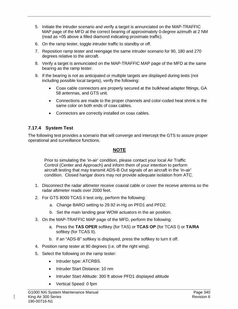
G1000 NXi System Maintenance Manual Page 340 King Air 300 Series Revision 6 190-00716-N1
5. Initiate the intruder scenario and verify a target is annunciated on the MAP-TRAFFIC MAP page of the MFD at the correct bearing of approximately 0-degree azimuth at 2 NM (read as +05 above a filled diamond indicating proximate traffic).
6. On the ramp tester, toggle intruder traffic to standby or off. 7. Reposition ramp tester and reengage the same intruder scenario for 90, 180 and 270
degrees relative to the aircraft. 8. Verify a target is annunciated on the MAP-TRAFFIC MAP page of the MFD at the same
bearing as the ramp tester. 9. If the bearing is not as anticipated or multiple targets are displayed during tests (not
including possible local targets), verify the following:
• Coax cable connectors are properly secured at the bulkhead adapter fittings, GA 58 antennas, and GTS unit.
• Connections are made to the proper channels and color-coded heat shrink is the same color on both ends of coax cables.
• Connectors are correctly installed on coax cables.
7.17.4 System Test The following test provides a scenario that will converge and intercept the GTS to assure proper operational and surveillance functions.
NOTE
Prior to simulating the ‘in-air’ condition, please contact your local Air Traffic Control (Center and Approach) and inform them of your intention to perform aircraft testing that may transmit ADS-B Out signals of an aircraft in the ‘in-air’ condition. Closed hangar doors may not provide adequate isolation from ATC.
1. Disconnect the radar altimeter receive coaxial cable or cover the receive antenna so the radar altimeter reads over 2000 feet.
2. For GTS 8000 TCAS II test only, perform the following: a. Change BARO setting to 29.92 in-Hg on PFD1 and PFD2. b. Set the main landing gear WOW actuators in the air position.
3. On the MAP-TRAFFIC MAP page of the MFD, perform the following: a. Press the TAS OPER softkey (for TAS) or TCAS OP (for TCAS I) or TA/RA
softkey (for TCAS II). b. If an “ADS-B” softkey is displayed, press the softkey to turn it off.
4. Position ramp tester at 90 degrees (i.e. off the right wing). 5. Select the following on the ramp tester:
• Intruder type: ATCRBS.
• Intruder Start Distance: 10 nm
• Intruder Start Altitude: 300 ft above PFD1 displayed altitude
• Vertical Speed: 0 fpm

G1000 NXi System Maintenance Manual Page 341 King Air 300 Series Revision 6 190-00716-N1
• Velocity: 360 kts 6. Initiate the intruder scenario and observe the following:
• The simulated intruder should be acquired at approximately 6-10 NM at 90 degree bearing. Observe intruder closes on own aircraft at a rate of 0.1 NM/sec. Verify that only a single simulated target is displayed in the expected quadrant (exclude possible local traffic).
• The simulated intruder should transition from Other Traffic (displayed as an open diamond with +03 displayed above), to proximate traffic (displayed as a filled white diamond with +03 displayed above), to a Traffic Advisory (TA) alarm (yellow filled circle with +03 displayed above.)
• For GTS 8000 TCAS II installations, the following applies: The simulated intruder should transition from a Traffic Advisory (displayed as a solid yellow circle with +03 displayed above), to a Resolution Advisory (RA) alarm (red filled square with +03 displayed above). Additionally, a Resolution Advisory is displayed on the vertical speed tape of PFD1 and PFD2 and an audible Resolution Advisory is heard over cockpit speakers and headphones.
NOTE
The aural TA annunciations are muted if the gear is extended and the Radar Altimeter indicates below 400 feet. For GTS 8000 TCAS II, to generate a DESCEND resolution advisory, the main landing gear must be in the in-air mode and the Radar Altimeter must read greater than 2,000 feet.
At the end of these tests, put the aircraft back ‘on-ground’ and restore radar altimeter operation.

G1000 NXi System Maintenance Manual Page 342 King Air 300 Series Revision 6 190-00716-N1
7.18 GDL 59 Original GDL 59 Reinstalled
No software or configuration loading is required if the removed GDL 59 is re-installed. This does not include units that were returned for repair as their software and configuration files are deleted during the repair testing process. Continue to the GDL 59 Test Section 7.18.4. New, Repaired or Exchange GDL 59 Installed
If a new, repaired or exchange GDL 59 is installed, the correct software and configuration files must be loaded to the unit. See Section 7.18.1 and then continue to the GDL 59 Test Section 7.18.4.
7.18.1 LRU Replacement Procedure GDL 59 1. Open the MFD, PFD 1 (PRI), PFD 1 (SEC), and PFD 2 circuit breakers. 2. Apply power to the G1000 system by connecting external power to the aircraft to
energize the aircraft and avionics electrical busses. 3. Turn on Avionics electrical busses. 4. Power on PFD2, MFD, and PFD1 in configuration mode. 5. Using the PFD1, scroll to the LRU replacement page. 6. Activate the curser and select GDL 59 in the LRU dropdown box. 7. Press the CHK All softkey. 8. Press the Load softkey. 9. Press ENT to acknowledge the process was complete. 10. Deactivate the curser. 11. Scroll to the Configuration Manager page. 12. Press the CNFM CFG softkey. 13. Select ok when prompted to “Confirm configuration as expected configuration” 14. Power cycle the system. Verify there are no red-Xs or system alerts. 15. If red-Xs or system alerts are present, troubleshoot as necessary using Section 5 or re-
load the system using the legacy method in Section 7.18.2. 16. If there are no red-Xs or system alerts, continue to Section 7.18.3.
7.18.2 Legacy Replacement Procedure GDL 59 (Alternate Method) 1. Insert the software loader card in the top slot of PFD1. 2. Power on PFD2, MFD, and PFD1 in configuration mode. 3. Select NO when “Do you want to update system files” is displayed on the screen of
PFD1. 4. Select the “SYSTEM UPLOAD” page using the small FMS knob on PFD1. 5. Activate cursor and rotate the small FMS knob to display the drop down menu. Rotate
the large FMS knob to highlight “07) Connext - SXM” and press ENT key on PFD1.

G1000 NXi System Maintenance Manual Page 343 King Air 300 Series Revision 6 190-00716-N1
6. Rotate the small FMS knob to display the drop down menu. Rotate the large FMS knob to highlight the installed GDL 59 configuration. Press ENT key on PFD1.
7. Press the CHK All softkey. 8. Press the Load softkey. 9. Monitor load progress. Verify software load completes without errors as indicated by the
following:
• Green “PASS” in the Configuration and Software columns for each item loaded.
• “Upload Complete………….COMPLETE” in the summary box. 10. Press ENT key on PFD1 to acknowledge upload complete. 11. Deactivate cursor. 12. Scroll to the Configuration Manager page. 13. Press the CNFM CFG softkey. 14. Select ok when prompted to “Confirm configuration as expected configuration” 15. Power cycle the system. Verify there are no red-Xs or system alerts. 16. If red-Xs or system alerts are present, troubleshoot as necessary using Section 5. 17. If there are no red-Xs or system alerts, continue to Section 7.18.3.
7.18.3 Activation of Garmin Connext In order to activate the optional GDL 59 and optional GSR 56 for Garmin Connext, contact Garmin Product Support at one of the following numbers (M-F, 7:00 a.m. to 7:00 p.m. Central Standard Time, - Central USA):
• 1.866.739.5687 (toll free in USA)
• +1.913.440.1135 (worldwide)
Have the following information ready prior to calling:
• If activating services for a GDL 59 installation o Aircraft tail number, serial number, manufacturer, and model o GDL 59 serial number o G1000 system ID number
Garmin Product Support will provide additional information for activation of data services. To obtain the G1000 system ID number and unit serial numbers, accomplish the following:
1. Turn the large FMS knob on the MFD to select the AUX page group. 2. Turn the small FMS knob to select the SYSTEM STATUS page. Record the SYSTEM ID
number shown in the AIRFRAME field. This number is unique for each G1000 system. 3. Press the LRU softkey to activate the cursor in the LRU INFO field. Use the large FMS
knob to scroll the cursor to GDL 59. Record the GDL 59 serial number shown in the LRU INFO field.

G1000 NXi System Maintenance Manual Page 344 King Air 300 Series Revision 6 190-00716-N1
7.18.4 GDL 59 Wi-Fi Data Link Functional Check This check verifies GDL 59 Wi-Fi Data Link interface is configured and is functional. This check requires an operating and available wireless network to be within range of the aircraft.
NOTE
This check only verifies the data output from the G1000 equipment. Any equipment/wiring added that is not part of the installation data will need separate testing and verification not covered as part of this document.
1. Start the G1000 System in Normal Mode. 2. Using the large FMS knob, select the AUX page group on the MFD. Using the small FMS
knob, select the AUX-REPORT STATUS page. 3. Press the WI-FI softkey on the MFD to select the AUX – WI-FI SETUP page. 4. Press the AVAIL softkey on the MFD to display the available WI-FI networks. 5. Press the FMS knob on the GCU to activate the cursor and rotate the small FMS knob to
highlight the desired network in the AVAILABLE NETWORKS field. 6. Press the CONNECT softkey on the MFD to connect to the network. (Skip to step 12 if the
selected network is a non-secure network.) 7. If the selected network is a secure network, enter the pass code in the ENTER
PASSPHRASE field in the WPA SECURITY SETTINGS pop-up window. 8. Press the ENT key on the GCU to accept the pass code, then press the ENT key on the
GCU again. 9. When the SAVE SETTINGS pop-up window is displayed, press the ENT key on the
GCU keypad to select SAVE CONNECTION. 10. Enter the appropriate airport identifier in the SELECT AN AIRPORT TO ASSOCIATE
WITH THE CONNECTION field, then press the ENT key on the GCU to accept the identifier.
11. With the CONNECT button highlighted, press the ENT key on the GCU to connect to the network.
12. Press the ENT key on the GCU if the verification window “Are you sure you want to connect?” is displayed.
13. Verify that the CONNECTION STATUS field on the AUX – WI-FI SETUP page on the MFD indicates CONNECTED.

G1000 NXi System Maintenance Manual Page 345 King Air 300 Series Revision 6 190-00716-N1
7.19 GSR 56 Original GSR 56 Reinstalled
No software or configuration loading is required if the removed GSR 56 is re-installed. This does not include units that were returned for repair as their software and configuration files are deleted during the repair testing process. Continue to the GSR 56 Test Section 7.14.3. New, Repaired or Exchange GSR 56 Installed
If a new, repaired or exchange GSR 56 is installed, the correct software and configuration files must be loaded to the unit. See Section 3.6 and then continue to the GSR 56 Test Section 7.14.3.
7.19.1 LRU Replacement Procedure GSR 56 LRU Replacement feature is not available for the GSR56, continue to Section 7.19.2.
7.19.2 Legacy Replacement Procedure GSR 56 (Alternate Method) 1. Insert the software loader card in the top slot of PFD1. 2. Power on PFD2, MFD, and PFD1 in configuration mode. 3. Select NO when “Do you want to update system files” is displayed on the screen of
PFD1. 4. Select the “SYSTEM UPLOAD” page using the small FMS knob on PFD1. 5. Activate cursor and rotate the small FMS knob to display the drop down menu. Rotate
the small FMS knob to highlight “07) Connext - SXM” and press ENT key on PFD1. 6. Rotate the small FMS knob to highlight the installed GSR 56 configuration. Press ENT
key on PFD1. 7. Verify the installed GSR 56 configuration is displayed in the “Item” window. 8. Press the CHK ALL key. 9. Press the Load softkey. 10. Monitor load progress. Verify software load completes without errors as indicated by the
following:
• Green “PASS” in the Configuration and Software columns for each item loaded.
• “Upload Complete………….COMPLETE” in the summary box. 11. Press ENT key on PFD1 to acknowledge upload complete. 12. Deactivate cursor. 13. Scroll to the Configuration Manager page. 14. Press the CNFM CFG softkey. 15. Select ok when prompted to “Confirm configuration as expected configuration” 16. Power cycle the system. Verify there are no red-Xs or system alerts. 17. If red-Xs or system alerts are present, troubleshoot as necessary using Section 5. 18. If there are no red-Xs or system alerts, continue to Section 7.19.3.

G1000 NXi System Maintenance Manual Page 346 King Air 300 Series Revision 6 190-00716-N1
7.19.3 Activation of Garmin Connext In order to activate the optional GSR 56 for Garmin Connext, contact Garmin Product Support at one of the following numbers (M-F, 7:00 a.m. to 7:00 p.m. Central Standard Time, - Central USA):
• 1.866.739.5687 (toll free in USA)
• +1.913.440.1135 (worldwide)
• Have the following information ready prior to calling: o Aircraft tail number, serial number, manufacturer, and model o GSR 56 serial number o G1000 system ID number o Name of aircraft owner and contact information o Credit card information
Garmin Product Support will provide additional information for activation of data services. To obtain the G1000 system ID number and unit serial numbers, accomplish the following:
1. Turn the large FMS knob on the MFD to select the AUX page group. 2. Turn the small FMS knob to select the SYSTEM STATUS page. Record the SYSTEM ID
number shown in the AIRFRAME field. This number is unique for each G1000 system. 3. Press the LRU softkey to activate the cursor in the LRU INFO field. Use the large FMS
knob to scroll the cursor to GSR1 (if GSR 56 is installed). Record the GSR 56 serial number shown in the LRU INFO field.
7.19.4 GSR 56 Functional Check 1. Power up the aircraft. 2. Using the large FMS knob, select the AUX page group on the MFD. Using the small
FMS knob, select the AUX-TELEPHONE page. 3. Ensure the system is showing Iridium signal strength (best if aircraft is outside). 4. Press TEL button on the pilot’s GMA. 5. Press the DIAL softkey on the MFD. 6. Enter the test phone number in the ENTER PHONE NUMBER field using the GCU
keypad. 7. Press the ENT key on the GCU keypad to accept the phone number. 8. Press the ENT key on the GCU keypad to initiate the dialing sequence. 9. When call is complete, press the HANGUP softkey on the AUX – TELEPHONE page on
the MFD to end the call.

G1000 NXi System Maintenance Manual Page 347 King Air 300 Series Revision 6 190-00716-N1
7.20 GSD 41 Original GSD 41 Reinstalled
No software or configuration loading is required if the removed GSD 41 is re-installed. This does not include units that were returned for repair as their software and configuration files are deleted during the repair testing process. New, Repaired or Exchange GDS 41 Installed
If a new, repaired or exchange GSD 41 is installed, the correct software and configuration files must be loaded to the unit. See Section 7.20.1.
7.20.1 LRU Replacement Procedure GSD 41 1. Open the MFD, PFD 1 (PRI), PFD 1 (SEC), and PFD 2 circuit breakers. 2. Apply power to the G1000 system by connecting external power to the aircraft to
energize the aircraft and avionics electrical busses. 3. Turn on Avionics electrical busses. 4. Power on PFD2, MFD, and PFD1 in configuration mode. 5. Using the PFD1, scroll to the LRU replacement page. 6. Activate the curser and select GSD 1 in the LRU dropdown box. 7. Press the CHK All softkey. 8. Press the Load softkey. 9. Press ENT to acknowledge the process was complete. 10. Deactivate the curser. 11. Scroll to the Configuration Manager page. 12. Press the CNFM CFG softkey. 13. Select ok when prompted to “Confirm configuration as expected configuration” 14. Power cycle the system. Verify there are no red-Xs or system alerts. 15. If red-Xs or system alerts are present, troubleshoot as necessary using Section 5 or re-
load the system using the legacy method in Section 7.20.2.
7.20.2 Legacy Replacement Procedure GSD 41 (Alternate Method) 1. Insert the software loader card in the top slot of PFD1. 2. Power on PFD2, MFD, and PFD1 in configuration mode. 3. Select NO when “Do you want to update system files” is displayed on the screen of
PFD1. 4. Select the “SYSTEM UPLOAD” page using the small FMS knob on PFD1. 5. Activate cursor and rotate the small FMS knob to display the drop down menu. Rotate
the large FMS knob to highlight “11) Non Garmin Options” and press ENT key on PFD1.
6. Rotate the small FMS knob to display the drop down menu. Rotate the large FMS knob to highlight “King Air – FDR Option”. Press ENT key on PFD1.

G1000 NXi System Maintenance Manual Page 348 King Air 300 Series Revision 6 190-00716-N1
7. Press the CHK All softkey. 8. Press the Load softkey. 9. Monitor load progress. Verify software load completes without errors as indicated by the
following:
• Green “PASS” in the Configuration and Software columns for each item loaded.
• “Upload Complete………….COMPLETE” in the summary box. 10. Press ENT key on PFD1 to acknowledge upload complete. 11. Deactivate cursor. 12. Scroll to the Configuration Manager page. 13. Press the CNFM CFG softkey. 14. Select ok when prompted to “Confirm configuration as expected configuration” 15. Power cycle the system verify there are no red-Xs or system alerts. 16. If red-Xs or system alerts are present, troubleshoot as necessary using Section 5.

G1000 NXi System Maintenance Manual Page 349 King Air 300 Series Revision 6 190-00716-N1
8. SUBSYSTEM FUNCTIONAL CHECKS 8.1 Non-Garmin Traffic System Functional Check
1. Select the Map – Traffic Map page on the MFD. 2. Verify that the TAS STBY, TAS OPER, Test, and ALT Mode softkeys are available on
the bottom of the MFD. Verify that an operating mode; STANDBY, OPERATE, or TEST (not TAS FAIL) is displayed in the upper left corner of the traffic map. Verify that NO DATA is not displayed in yellow in the center of the display over the aircraft symbol.
NOTE
If the ALT Mode softkey is not displayed, the G1000 has not been properly configured for the traffic system. Reference Section 3.8.13, to enable the traffic system.
3. Press the TAS OPER softkey and verify that TAS: OPERATING is displayed in the
upper left corner of the traffic map. 4. Press the TAS STBY softkey and verify that TAS: STANDBY is displayed in the upper
left corner of the traffic map. 5. Press the Test softkey and verify that TAS: TEST is displayed in the upper left corner of
the traffic map and a traffic test pattern is displayed. Upon completion of the test, verify that “TAS SYSTEM TEST OK” is heard over the cockpit speaker.
NOTE This annunciated traffic system test message may be different from the traffic system installed on subject aircraft.
6. Open the TRFC circuit breaker on the avionics circuit breaker panel. On the MFD, verify
that NO DATA is displayed in yellow after several seconds. 7. Close the TRFC circuit breaker on the avionics circuit breaker panel and verify that NO
DATA is removed after several seconds. If no other service is to be performed, continue to the return-to-service checks in Section 9.

G1000 NXi System Maintenance Manual Page 350 King Air 300 Series Revision 6 190-00716-N1
8.2 Stormscope Functional Check Reference Section 3.18.1, for Stormscope configuration. This procedure assumes familiarity with the set-up and operation of the WX-PA portable analyzer kit if required.
1. Apply power to the WX-500 and verify that no failed test messages appear. If fault
messages do appear, refer to the WX-500 Installation Manual for troubleshooting. 2. Following successful power up, verify the following modes:
• All available ranges can be displayed.
• Access to the cell mode and strike mode.
• Strike counter is displayed in all weather modes and ranges. 3. Key COM1 and COM2 several times on different frequencies representing the lower, mid
and upper portion of the VHF COM frequency band. Verify keying of COM1 or COM2 does not cause strike data to appear on the MFD.
4. Operate DME, XPDR 1, XPDR 2 and weather radar. Verify these systems do not cause strike data to appear on the MFD.
5. Connect the WX-PA cable to the WX-PA antenna. 6. Position the WX-PA antenna on the WX-500 antenna. Ensure the connection is tight. If
necessary, use tape to secure the WX-PA antenna. Ensure the “FORWARD” arrows are aligned and the WX-PA antenna suction cups are positioned forward of center along the longitudinal axis.
7. Secure the WX-PA cable to the aircraft with the attached suction cup and route the cable to the cockpit.
8. Connect the remaining cable end to the WX-PA. 9. Power up the WX-PA and verify the WX-500 is in the weather mapping mode. 10. Set the WX-500 to STRIKE mode; 100 NM range (or next highest available range). 11. Select the Continuous Out mode displayed on the WX-PA menu and press
MENU/ENTER. 12. Select the bottom mount antenna configuration on the WX-PA keyboard (“A” key). 13. Select a cardinal bearing and a range of 120 NM. 14. Use the F1 and F2 keys to adjust range and F3 and F4 keys to adjust heading.
NOTE
The WX-500 will plot data at one-half the range selected on the WX-PA.

G1000 NXi System Maintenance Manual Page 351 King Air 300 Series Revision 6 190-00716-N1
15. Press MENU/ENTER to start the test. 16. Observe the MFD to ensure the proper positioning of the strikes, based on range and
azimuth settings on the WX-PA. Change the cardinal bearings and verify correct test strikes. Verify the strikes are within 10 degrees of the selected azimuth and plot at 60NM (1/2 120 NM).
17. Verify after 20 seconds of operation the strike counter reads 580 +/-40. 18. After testing for all ranges and bearings indicated, press 2ND then MENU/ENTER to
return to the main menu. 19. Select Circular Pattern mode on the WX-PA mode menu and press MENU/ENTER. 20. Select bottom mount antenna configuration on the WX-PA keyboard (“A” key).
NOTE The MFD should be set at 100 NM (or next highest available range) on the 360-degree weather screen and in strike mode.
21. Use the F1 and F2 keys to select 120 NM range and press MENU/ENTER to start the
test. Verify the WX-500 plots discharge points at approximately 60 NM. 22. Observe the MFD to ensure the proper positioning of the test strikes. Verify the strikes
are within 10 degrees of the 30-degree azimuth increment and within 12 NM of 60 NM, 23. When complete, set WX-PA for 55 NM, set the MFD for 50 NM (or the next highest
available range) and repeat test. 24. On the MFD, verify the sensor plots points just outside of 25 NM and the strikes are
within 10 degrees of the 30-degree azimuth and within 5 NM of 27.5 NM. 25. Repeat above setting the MFD for 25 NM (or the next highest available range) and the
WX-PA for 15 NM. 26. On the MFD, verify the positioning of test strikes are within 10 degrees of azimuth and
within 2 NM of 7.5 NM. 27. Restart the G1000 in configuration mode by opening the PFD and MFD circuit breakers.
While holding the ENT keys on the PFDs and MFD, restore power by closing the PFDs and MFD circuit breakers.
28. Select the OTHER page group on the MFD. The Map - Stormscope Map page is shown by default.
If no other service is to be performed, continue to the return-to-service checks in Section 9.

G1000 NXi System Maintenance Manual Page 352 King Air 300 Series Revision 6 190-00716-N1
8.3 TAWS Functional Check 8.3.1 Functional Check for TAWS-B
1. With the G1000 in Normal Mode, use the GCU FMS knob to select the Map group and TAWS page on the MFD.
2. Verify that the title at the top of the page reads “Map – TAWS-B Map”. NOTE
If TAWS has not been enabled, the title will read “Map – Terrain Proximity” or “Map – Terrain”. Refer to Section 3.9.6 for TAWS B Configuration for enabling this feature.
3. Press the GCU MENU button and select “Test TAWS System” from the pop-up menu. Verify TAWS test annunciation is displayed on the MFD and both PFDs.
4. After the TAWS test has completed, verify that “TAWS System Test Okay” is heard over the cockpit speaker (if selected) and the headsets.
5. Press the GCU MENU button again and select “Inhibit TAWS” from the pop-up menu and press ENT on the GCU. Verify “TAWS INH” is displayed on PFD 1 and PFD 2.
6. Press the GCU MENU button again and select “Enable TAWS” from the pop-up menu and press ENT on the GCU. Verify the “TAWS INH” annunciation on the PFDs has extinguished.
7. With a GPS position acquired, shield or disconnect the GPS antennas to remove the GPS signal. Verify “LOI” shows on the MFD and the “TAWS N/A” and “LOI” annunciations show on the PFDs.
8. Reconnect or remove the shield from the GPS antennas, and verify the MFD “LOI” indication and PFD “TAWS N/A” and “LOI” annunciations are removed once the GPS satellites are acquired.
9. Pull PFD1 PRI and PFD1 SEC circuit breakers. Re-power PFD1 in configuration mode, and use the PFD1 FMS knob to select the System Audio - Audio Alert Configuration page.
10. Ensure cockpit speaker is selected ON. Use the PFD1 FMS knob to highlight each of the following messages then select PLAY. Verify each of the following audio messages are played:
• Too Low Terrain
• Sink Rate
• Pull Up
• Don’t Sink
• Five Hundred
• Caution, Terrain (2X)
• Terrain (2X), Pull Up (2X)
• Caution, Obstacle (2X)
• Obstacle (2X), Pull Up (2X)
• Terrain Ahead (2X)
• Terrain Ahead, Pull Up (2X)

G1000 NXi System Maintenance Manual Page 353 King Air 300 Series Revision 6 190-00716-N1
• Obstacle Ahead (2X)
• Obstacle Ahead, Pull Up (2X) 11. Pull the PFD1 PRI and PFD1 SEC circuit breakers, and re-power PFD1 in normal
operating mode. 12. If no other service is to be performed, continue to the return-to-service checks in Section
9.
8.3.2 Functional Check for TAWS-A 1. With the G1000 in Normal Mode, use the GCU FMS knob to select the Map group and
TAWS page on the MFD. 2. Verify that the title at the top of the page reads “Map – TAWS-A Map”.
NOTE If TAWS has not been enabled, the title will read “Map – Terrain Proximity” or “Map – Terrain”. Refer to Section 3.9.8 for enabling TAWS-A.
3. Press the GCU MENU button and select “Test TAWS System” from the pop-up menu. Verify TAWS test annunciation is displayed on the MFD and both PFDs.
4. After the TAWS test has completed, verify that “TAWS System Test Okay” is heard over the cockpit speaker (if selected) and the headsets.
5. Press the GCU MENU button again and select “Inhibit TAWS” from the pop-up menu and press ENT on the GCU. Verify “TAWS INH” is displayed on PFD 1 and PFD 2.
6. Press the GCU MENU button again and select “Enable TAWS” from the pop-up menu and press ENT on the GCU. Verify the “TAWS INH” annunciation on the PFDs has extinguished.
7. Press the GCU MENU button again and select “Inhibit GPWS” from the pop-up menu and press ENT on the GCU. Verify “GPWS INH” is displayed on PFD 1 and PFD 2.
8. Press the GCU MENU button again and select “Enable GPWS” from the pop-up menu and press ENT on the GCU. Verify the “GPWS INH” annunciation on the PFDs has extinguished.
9. Press the GCU MENU button again and select “Flap Override” from the pop-up menu and press ENT on the GCU. Verify “FLAP OVR” is displayed on PFD 1 and PFD 2.
10. Press the GCU MENU button again and select “Disable Flap Override” from the pop-up menu and press ENT on the GCU. Verify the “FLAP OVR” annunciation on the PFDs has extinguished.
11. With a GPS position acquired, shield or disconnect the GPS antennas to remove the GPS signal. Verify “LOI” shows on the MFD and the “TAWS N/A” and “LOI” annunciations show on the PFDs.
12. Reconnect or remove the shield from the GPS antennas and verify the MFD “LOI” indication and PFD “TAWS N/A” and “LOI” annunciations are removed once the GPS satellites are acquired.
13. Pull the RADIO ALTM circuit breaker. Verify “GPWS FAIL” is displayed on PFD1 and PFD2.
14. Reset the RADIO ALTM circuit breaker. Verify “GPWS FAIL” annunciations are removed.
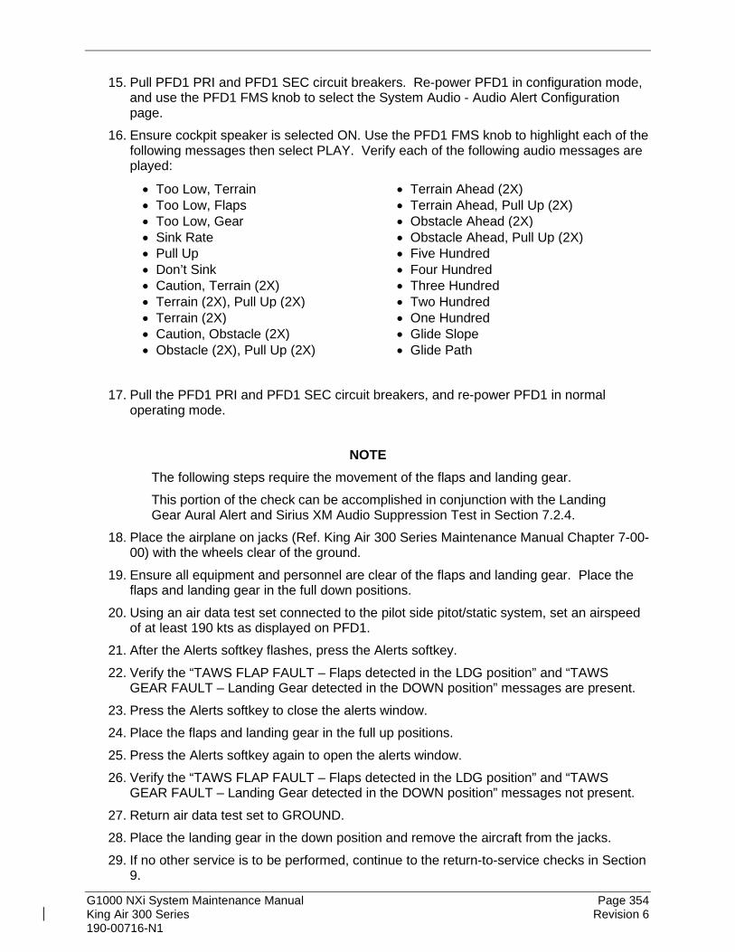
G1000 NXi System Maintenance Manual Page 354 King Air 300 Series Revision 6 190-00716-N1
15. Pull PFD1 PRI and PFD1 SEC circuit breakers. Re-power PFD1 in configuration mode, and use the PFD1 FMS knob to select the System Audio - Audio Alert Configuration page.
16. Ensure cockpit speaker is selected ON. Use the PFD1 FMS knob to highlight each of the following messages then select PLAY. Verify each of the following audio messages are played:
• Too Low, Terrain • Terrain Ahead (2X) • Too Low, Flaps • Terrain Ahead, Pull Up (2X) • Too Low, Gear • Obstacle Ahead (2X) • Sink Rate • Obstacle Ahead, Pull Up (2X) • Pull Up • Five Hundred • Don’t Sink • Four Hundred • Caution, Terrain (2X) • Three Hundred • Terrain (2X), Pull Up (2X) • Two Hundred • Terrain (2X) • One Hundred • Caution, Obstacle (2X) • Glide Slope • Obstacle (2X), Pull Up (2X) • Glide Path
17. Pull the PFD1 PRI and PFD1 SEC circuit breakers, and re-power PFD1 in normal
operating mode.
NOTE The following steps require the movement of the flaps and landing gear. This portion of the check can be accomplished in conjunction with the Landing Gear Aural Alert and Sirius XM Audio Suppression Test in Section 7.2.4.
18. Place the airplane on jacks (Ref. King Air 300 Series Maintenance Manual Chapter 7-00-00) with the wheels clear of the ground.
19. Ensure all equipment and personnel are clear of the flaps and landing gear. Place the flaps and landing gear in the full down positions.
20. Using an air data test set connected to the pilot side pitot/static system, set an airspeed of at least 190 kts as displayed on PFD1.
21. After the Alerts softkey flashes, press the Alerts softkey. 22. Verify the “TAWS FLAP FAULT – Flaps detected in the LDG position” and “TAWS
GEAR FAULT – Landing Gear detected in the DOWN position” messages are present. 23. Press the Alerts softkey to close the alerts window. 24. Place the flaps and landing gear in the full up positions. 25. Press the Alerts softkey again to open the alerts window. 26. Verify the “TAWS FLAP FAULT – Flaps detected in the LDG position” and “TAWS
GEAR FAULT – Landing Gear detected in the DOWN position” messages not present. 27. Return air data test set to GROUND. 28. Place the landing gear in the down position and remove the aircraft from the jacks. 29. If no other service is to be performed, continue to the return-to-service checks in Section
9.

G1000 NXi System Maintenance Manual Page 355 King Air 300 Series Revision 6 190-00716-N1
8.4 FliteCharts Functional Check FliteCharts is enabled by default and only turned off if the ChartView Only option file has been loaded. Reference Section 3.8.12 (FliteCharts) or Section 3.9.2 (Dual Charts) for configuring FliteCharts.
NOTE This test is required only if FliteCharts or Dual Charts is enabled.
1. If Dual Charts are installed, ensure FliteCharts are set as the preferred charts. 2. With the G1000 in Normal Mode, use the GCU FMS knob to select Aux – System
Status page, then select MFD1 DB softkey. 3. Use the small FMS knob to scroll to CHART. 4. Verify “FliteCharts” is displayed in blue text adjacent to “CHART”. 5. Verify the FliteCharts database cycle number is displayed in blue text and the
FliteCharts database is current. 6. Deactivate the cursor and use the GCU large FMS knob to select the Map - Navigation
Map page then press the Charts softkey. 7. Verify the airport chart is displayed and the following softkeys are displayed (some
softkeys may be grayed out):
• CHRT OPT
• Show Map
• INFO 1
• DP
• STAR
• APR
• WX
• NOTAM
• Go Back 8. Press the CHRT OPT softkey and verify the following softkeys are displayed (some
softkeys may be grayed out):
• All
• Header
• Plan
• Profile
• Minimums
• Fit WDTH
• Full SCN
• Back 9. If no other service is to be performed, continue to the return-to-service checks in Section
9.

G1000 NXi System Maintenance Manual Page 356 King Air 300 Series Revision 6 190-00716-N1
8.5 ChartView Functional Check ChartView must be enabled using a ChartView or Dual Charts Enable Card. Reference Section 3.9.1 (ChartView only) or 3.9.2 (Dual Charts) for enabling procedures.
NOTE The required ChartView databases are subscription-based and are to be procured by the aircraft owner directly from Jeppesen.
1. If Dual Charts are installed, ensure ChartView are set as the preferred charts. 2. With the G1000 in Normal Mode, use the GCU FMS knob to select ‘Aux – System
Status’ page, then select MFD1 DB softkey. 3. Use the small FMS knob to scroll to CHART. 4. Verify “ChartView” is displayed in blue text adjacent to CHART. 5. Verify the ChartView database cycle number is displayed in blue text and the ChartView
database is current. 6. Deactivate the cursor and use the large GCU FMS knob to select the Navigation Map
Page then press the Charts softkey. 7. Verify the airport chart is displayed and the following softkeys are displayed (some
softkeys may be grayed out):
• CHRT OPT • APR • Show Map • WX • INFO-1 • NOTAM • DP • Go Back • STAR
8. Press CHRT OPT softkey and verify the following softkeys are displayed (some softkeys may be grayed out):
• All
• Header
• Plan
• Profile
• Minimums
• Fit WDTH
• Full SCN
• Back 9. If no other service is to be performed, continue to the return-to-service checks in Section
9.

G1000 NXi System Maintenance Manual Page 357 King Air 300 Series Revision 6 190-00716-N1
8.6 SafeTaxi Functional Check The maximum map ranges for enhanced detail are configurable by the flight crew. When zoomed in close enough to show the airport detail, the map reveals runways with numbers, taxiways with identifying letters/numbers, and airport landmarks including ramps, buildings, control towers, and other prominent features. Resolution is greater at lower map ranges. When the aircraft location is within the screen boundary, including within SafeTaxi ranges, an airplane symbol is shown on any of the navigation map views for enhanced position awareness. Any map page that displays the navigation view can also show the SafeTaxi airport layout, within the maximum configured range. The following is a list of pages where the SafeTaxi feature can be seen:
• Navigation Map Page
• Inset map
• Weather Datalink Page
• Airport Information Page
• Intersection Information Page
• NDB Information Page
• VOR Information Page
• User Waypoint Information Page
• Trip Planning Page
• Nearest Pages
1. Use the FMS knob on the GCU to select the Aux – System Status page and select MFD1 DB softkey. Use the small FMS knob to scroll to CHART category and verify “FliteCharts” is displayed in blue text adjacent to “CHART”.
2. Verify the FliteCharts database ‘Region’, ‘Cycle’ number, ‘Effective’, ‘Expires’, and ‘Disables’ dates of the subscription appear in cyan text.
3. Use the FMS knob on the GCU to select Map - Navigation Map page. 4. On the GCU, press MENU. With Map Setup highlighted, press ENT on the GCU. Rotate
the small GCU FMS knob to select the Aviation group and press the ENT key on GCU. 5. Turn the GCU large FMS Knob to scroll through the Aviation Group options to ‘SafeTaxi’. 6. Turn the GCU small FMS Knob to display the range of distances. 7. Turn the GCU FMS Knob to select 5000ft as the distance for maximum SafeTaxi display
range, and then press the GCU ENT key to complete the selection. 8. Using the GCU range knob, select a range of 5000ft or less. Verify SafeTaxi display
represents the current aircraft location and the airport layout. 9. If no other service is to be performed, continue to the return-to-service checks in Section
9.

G1000 NXi System Maintenance Manual Page 358 King Air 300 Series Revision 6 190-00716-N1
8.7 SYNTHETIC VISION (SVS) Functional Check This check verifies that the SVS enablement feature (if installed) is loaded properly and can be synchronized on both PFDs.
1. Press the PFD Opt softkey on each PFD. 2. Press the SVT softkey on each PFD. 3. Press Terrain softkey on PFD1 and verify the SVS for PFD1 is turn ON. 4. Press Terrain softkey on PFD2 and verify the SVS for PFD2 is turn ON. 5. Press the Terrain softkey on PFD1 and verify the SVS display cycles ON or OFF on
both PFDs with each press of the Terrain Softkey. 6. Press the Terrain softkey on PFD2 and verify the SVS display cycles ON or OFF on
both PFDs with each press of the Terrain Softkey. 7. Press the Back Softkey twice on both PFDs to return to the top-level softkeys
Note: Synthetic Vision (SVS) Function Check must be performed after every software and configuration load.

G1000 NXi System Maintenance Manual Page 359 King Air 300 Series Revision 6 190-00716-N1
8.8 DME Functional Check This check verifies that the DME-to-G1000 interface operates correctly.
NOTE Support for a single Collins DME-42 system is provided as an option in the G1000. If the DME option is selected, the DME channel one audio level must be adjusted by the procedure contained within Collins DME-42 Transceiver Repair Manual 523-0772458, Maintenance Section 523-0772460-006118, to adjust DME channel one audio level. Recommended nominal DME audio output level is 4.46 Vpp + 0.10 Vpp. Procedure must be accomplished by an approved repair station.
1. If DME is not displayed, press the PFD softkeys on PFD1 and PFD2, then press the
DME softkey. Verify the DME window is displayed next to the PFD1 and PFD2 HSI. 2. On PFD1 and PFD2, press the Back softkey then select DME softkeys. Verify the DME
TUNING screen is displayed. 3. On PFD1 and PFD2, use the large FMS knob to select the NAV1, NAV2 and HOLD
modes in the DME field. Verify that the NAV1, NAV2 and HOLD modes can be selected by turning the small FMS knob.
4. Set NAV1 and NAV2 frequencies to 108.00 and 117.00 respectively. 5. On PFD1 and PFD2, select the DME NAV1 mode. Verify that the DME window display
is set to the NAV1 frequency of 108.00. 6. On PFD1 and PFD2, select the DME NAV2 mode by pressing the ENT softkey. Verify
that the DME window display is set to the NAV2 frequency of 117.00. 7. On PFD1 and PFD2, select the DME HOLD mode by using the FMS knob. Verify that
the last selected NAV frequency of 117.00 remains the same when the NAV2 frequency is changed. Deselect DME HOLD.
8. On the NAV Test Set, set up a DME test and note the NAV frequency. Tune NAV 1 to the test set frequency and set PFD1 and PFD2 DME MODE to NAV1. Set NAV 2 to a frequency other than the test set frequency.
9. Verify that the DME distance on PFD1 and PFD2 match the test set. 10. Select, or verify selected, DME and SPKR buttons on GMA1 and GMA2 audio panels to
select the DME audio and select speaker to ON. Verify that the DME audio can be heard over the cockpit speakers.
11. On PFD1 and PFD2, set the DME mode to NAV2 and verify that the DME distance is dashed out.
12. Tune NAV 2 to the test set frequency. Set NAV 1 to a frequency other than the test set frequency.
13. Verify that the DME distance on PFD1 and PFD2 match the test set. 14. If no other service is to be performed, continue to the return-to-service checks in Section
9.

G1000 NXi System Maintenance Manual Page 360 King Air 300 Series Revision 6 190-00716-N1
8.9 ADF Functional Check
This check verifies that the ADF / G1000 interface operates correctly. 1. Press the PFD softkey on PFD1 and PFD2. Toggle the BRG1 and BRG2 softkey until
the ADF bearing is shown on PFD1 and PFD2. 2. Verify that the ADF window is not invalid (no red ‘X’). 3. Using the ADF control head select a known valid local ADF. Verify that the ADF bearing
pointer moves towards a bearing and stabilizes. 4. Select ADF and SPKR on GMA1 and GMA2. Using the ADF control head, select, ANT
mode. Verify that the audio from the station tuned can be heard on the pilot and copilot headset and cockpit speaker.
5. Increment the ADF volume control from full low to full high. Verify the volume increases and decreases appropriately over pilot and copilot headset and cockpit speaker.
6. If no other service is to be performed, continue to the return-to-service checks in Section 9.
8.10 GRA 5500 Radar Altimeter Functional Check This check verifies that the G1000/radar altimeter interface is operates correctly.
1. Navigate to the Aux – System Status page on the MFD. 2. Press the RA Test softkey and verify that the “RA TEST” annunciation is displayed on
both PFDs. 3. Verify 40 feet is displayed in the RA display window on both PFDs. 4. Press the RA Test softkey again. Verify the RA readout window decreases to 0 feet on
PFD1 and PFD2. 5. Pull the RADIO ALTM circuit breaker. Verify on PFD 1 and PFD 2 that an RA FAIL
message is displayed. 6. Reset the RADIO ALTM circuit breaker. 7. If no other service is to be performed, continue to the return-to-service checks in Section
9.
8.11 Non-Garmin Radar Altimeter Check (Optional) This check verifies that the G1000 / radar altimeter interface is operates correctly.
NOTE This check only verifies the data output from the G1000 equipment. Any equipment/wiring added that is not part of the installation data will need separate testing and verification not covered as part of this document.
1. Navigate to the Aux – System Status page on the MFD. 2. Press the RA Test softkey and verify that “RA TEST” annunciation is displayed on both
PFDs. 3. Verify 50 feet is displayed in the RA display window on both PFDs.

G1000 NXi System Maintenance Manual Page 361 King Air 300 Series Revision 6 190-00716-N1
4. Press the RA Test softkey again. Verify the RA readout window displays 2500 feet and decreases to 0 feet on PFD1 and PFD 2.
5. Pull the RADIO ALTM circuit breaker. Verify on PFD 1 and PFD 2 that an RA FAIL message is displayed.
6. Reset the RADIO ALTM circuit breaker. 7. If no other service is to be performed, continue to the return-to-service checks in Section
9.
8.12 Weight on Wheels and Low Speed Awareness Band Check This procedure will verify that the GDU air ground status uses valid Weight on Wheels (WOW) inputs.
1. Ensure aircraft is positioned with weight on wheels. 2. Apply external power to the aircraft. Set BATT and AVIONICS MASTER switches to ON
and wait for all aircraft and avionics systems to complete their initialization and begin operating normally.
3. Verify there are no WOW INVALID or WOW FAULT messages. Refer to Section 5.2 to troubleshoot messages.
4. Verify the Low Speed Awareness band (red band) is NOT displayed on the PFD1 and PFD2 airspeed tapes (see Figure 8-1).
NOTE This portion of the check can be accomplished in conjunction with the Landing Gear Aural Alert and Sirius XM Audio Suppression Test in Section 7.2.4.
5. Place the airplane on jacks (Ref. King Air 300 Series Maintenance Manual Chapter 7-00-00) with the wheels clear of the ground.
6. Verify there are no WOW INVALID or WOW FAULT messages. Refer to Section 5.4 to troubleshoot messages.
7. Verify the Low Speed Awareness band (red band) appears at the low end of the Air Speed Tape on the PFD1 and PFD2 (see Figure 8-1).
8. Remove airplane from jacks. 9. If no other service is to be performed, continue to the return-to-service checks in Section
9.

G1000 NXi System Maintenance Manual Page 362 King Air 300 Series Revision 6 190-00716-N1
Figure 8-1, Low Speed Awareness Band Symbolization
8.13 RVSM Checks The following are required initial and continued airworthiness checks to verify proper configuration for operation in RVSM airspace. RVSM operations are prohibited until the all of the RVSM checks are completed successfully. Any changes to the aircraft external configuration, such as the installation of additional antennas, probes, fairings or radome along the sides of the airplane, that may impact the air data system or aircraft performance may also invalidate the RVSM certification for this aircraft.
8.13.1 RVSM Required Avionics Check With the PFD in configuration mode, select the Aux – System Status page using the small FMS knob. Press the small FMS knob to activate the cursor. Highlight each of the following items in the LRU window and verify that the required software part number and version matches the information in the General Arrangement drawing listed in Table 1-1. Verify hardware part number by visual inspection of the units. Record the results in Table 8-1 (next page).

G1000 NXi System Maintenance Manual Page 363 King Air 300 Series Revision 6 190-00716-N1
Table 8-1, RVSM Required Avionics
ITEM
HARDWARE OK
SOFTWARE OK
SYSTEM STATUS REPORT DESCRIPTION PART
NUMBER DESCRIPTION PART NUMBER VER
1 GIA 63W IAU #1
or GIA 64E IAU #1
MAIN SUB-SYSTEM GIA1
AUDIO GIA1 AUDIO
GPS/WAAS ENGINE GPS1
CERTIFICATION GAINS
GFC CERT GIA
1
2 GIA 63W IAU #2
or GIA 64E IAU #2
MAIN SUB-SYSTEM GIA2
AUDIO GIA2 AUDIO
GPS/WAAS ENGINE GPS2
CERTIFICATION GAINS
GFC CERT GIA
2
3 GDU 1050A PFD#1
SYSTEM PFD1
FPGA PFD1 FPGA
4 GDU 1050A PFD#2
SYSTEM PFD2
FPGA PFD2 FPGA
5 GDU 1550 MFD SYSTEM MFD1
FPGA MFD FPGA
6 GSU 75B GDC 7400
ADC #1
SYSTEM GDC1
FPGA GDC1 FPGA
7 GSU 75B GDC 7400
ADC #2
SYSTEM GDC2
FPGA GDC2 FPGA
8*
GTX 33(D) GTX 3000 GTX 335R GTX 345R XPDR #1
GTX
33/3000/335/345 SYSTEM
GTX1
9* GTX 33(D) GTX 3000 GTX 335R XPDR #2
GTX
33/3000/335 SYSTEM
GTX2
* Any other transponder that meets or exceeds the requirements of TSO-C74c (Mode C) or TSO-C112 (Class 2a; Mode S) may be installed.

G1000 NXi System Maintenance Manual Page 364 King Air 300 Series Revision 6 190-00716-N1
8.13.2 RVSM Critical Region Visual Inspection The RVSM critical region is a 24 x 24 inch area around the static ports on both sides of the airplane. The corners of the RVSM critical region are to be marked on the aircraft with placards or paint of a contrasting color (see Figure 8-2). The RVSM critical region must meet the following visual inspection criteria:
1. The fuselage skin must be free from damage. All skin repairs within the RVSM critical region must be flush (no external doublers). If any damage is found, the area must be repaired. Locations of existing protruding head rivets in frames and skin laps are acceptable.
2. The paint (including stripes) must be uniform and smooth. Remove any paint blisters or flaking and sand smooth. Any decals or placards must be flush with no peeling edges.
3. The static ports must be free from any corrosion, elongation of holes, deformation or obstructions. If any damage is found, replace the static port.
4. The oxygen servicing door on the right hand side must close approximately flush with the fuselage skin and be free from damage or deformation. For the model 300 only, the ELT access hole cover on the right hand side must be in place.
12 INCHES
12 INCHES
14 INCHES10 INCHES
AFT CORNER MARKING - TYPICAL(USE CONTRASTING COLOR)
STATIC PORTS
OXYGEN SERVICING DOOR(RH SIDE ONLY)
ELT ACCESS HOLE(RH SIDE ONLY)
AFT
Figure 8-2, RVSM Critical Region
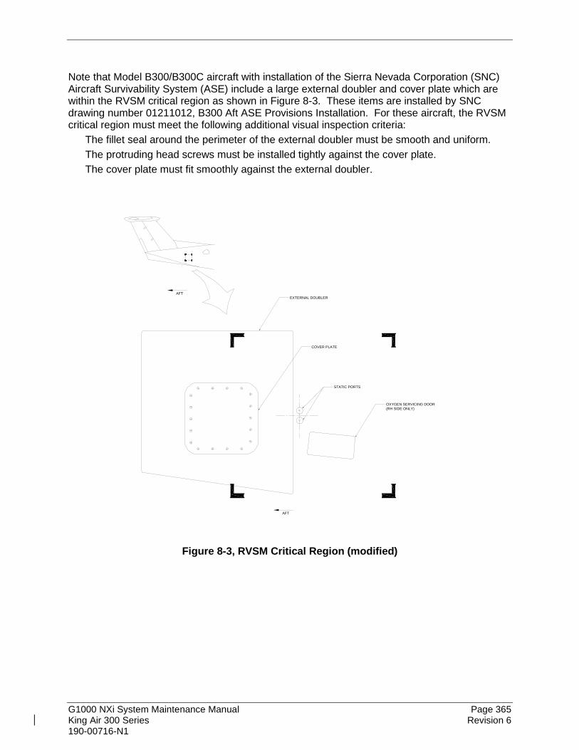
G1000 NXi System Maintenance Manual Page 365 King Air 300 Series Revision 6 190-00716-N1
Note that Model B300/B300C aircraft with installation of the Sierra Nevada Corporation (SNC) Aircraft Survivability System (ASE) include a large external doubler and cover plate which are within the RVSM critical region as shown in Figure 8-3. These items are installed by SNC drawing number 01211012, B300 Aft ASE Provisions Installation. For these aircraft, the RVSM critical region must meet the following additional visual inspection criteria:
The fillet seal around the perimeter of the external doubler must be smooth and uniform. The protruding head screws must be installed tightly against the cover plate. The cover plate must fit smoothly against the external doubler.
AFT
STATIC PORTS
OXYGEN SERVICING DOOR(RH SIDE ONLY)
AFT
COVER PLATE
EXTERNAL DOUBLER
Figure 8-3, RVSM Critical Region (modified)

G1000 NXi System Maintenance Manual Page 366 King Air 300 Series Revision 6 190-00716-N1
8.13.3 RVSM Static Port Height Inspection The Gauging Assembly p/n SPF-4 (A1M-BCH-GE) is available from Beechcraft. Any alternate tool authorized in the King Air 300 Series Maintenance Manual for RVSM static port measurements may be substituted for this tool. Initialize the tool as follows:
1. Make sure the dial indicator reads negative when the plunger is pressed and positive when the plunger is free.
2. Place the gauging assembly on a flat surface (gauge block or equivalent.) 3. Ensure the smaller needle is at approximately (.1). 4. Rotate the dial indicator to set the large needle at (0) as shown in Figure 8-4.
DIAL INDICATOR
Figure 8-4, Dial Indicator
The static port measurements are obtained at four locations on each static port as shown in Figure 8-6. These measurements are used to find an AVERAGE and ANGLE for each of the four static ports. The AVERAGE is calculated by adding the four measurements and dividing the total by 4. The ANGLE is calculated by subtracting the minimum measurement from the maximum measurement. The calculated AVERAGE and ANGLE for each static port must fall within the ranges shown in Table 8-2 Perform the static port measurement as follows:
1. Wipe the surface of static ports clean with isopropyl alcohol. 2. Place the gauging assembly onto the static port surface as shown in Figure 8-5.Figure
8-5

G1000 NXi System Maintenance Manual Page 367 King Air 300 Series Revision 6 190-00716-N1
DIAL INDICATOR
GAGING ASSEMBLY
STATIC PORT
FUSELAGE SKIN
Figure 8-5, Static Port Measurement
NOTE The dial indicator shows 0.100 inch when completely flush. Therefore, subtract the readings from 0.100 inch to determine the actual static port height. This should be completed before making any calculations.
3. For each static port, measure the static port height at the A, B, C and D locations as
shown in Figure 8-6. Record the measurements in the measurement log shown in Table 8-2.
4. Calculate the AVERAGE for each static port using the measurements by adding the four measurements and dividing the total by 4. Record the AVERAGE in the measurement log
5. Ensure the AVERAGE for each static port is within tolerance (+0.045 to +0.085 inch.) If it is not, remove and reinstall the static ports as necessary to meet the tolerance.
6. Calculate the ANGLE for each static port by subtracting the smallest of the A, B, C or D measurements from the largest of the A, B, C or D measurements. Record the ANGLE in the measurement log.
7. Ensure the ANGLE for each static port is within tolerance (0.000 to +0.026 inch.) If it is not, remove and reinstall the static ports as necessary to meet the tolerance.
A
B
C
D
Figure 8-6, Static Port Measurement locations

G1000 NXi System Maintenance Manual Page 368 King Air 300 Series Revision 6 190-00716-N1
Table 8-2, Static Port Measurement Log
A B C D AVERAGE (A+B+C+D)/4
ANGLE Largest - Smallest
UPPER LEFT
LOWER LEFT
UPPER RIGHT
LOWER RIGHT
Aircraft s/n:
Date:
8.13.4 RVSM Air Data System Check Perform the Air Data Test per Section 7.7.3. If either the pilot or copilot air data system does not meet the tolerances specified, have maintenance checks performed on the air data system or the pitot/static system.
IMPORTANT! RVSM operations are prohibited until the air data system meets all test conditions.
8.13.5 RVSM In-Flight Altitude Hold Check RVSM operation requires that the autopilot system accurately maintain the acquired altitude during non-turbulent, non-gust cruise conditions. The autopilot must be maintained in accordance with the G1000 System Maintenance Manual listed in Table 1-2. The autopilot must be shown to meet the performance specification of the following in-flight altitude hold test.
1. Verify the following conditions (normal RVSM cruise flight): • Altitude FL290 to FL350 • Altimeter setting 29.92 in Hg (1013 HPA) • Autopilot altitude hold engaged • Non-turbulent, non-gust conditions
2. Record the data from the primary cockpit displays as specified in Table 8-3 every 5 minutes for a minimum flight segment of 30 minutes in length. The maximum altitude deviation shown on the display throughout the test should not exceed ±65 feet.
If the aircraft fails to hold altitude to this tolerance, repeat the test ensuring that the airspeed remains constant and the air remains stable during the entire test. If the test still fails, have maintenance checks performed on the GFC 700 system, then repeat the test. RVSM operations are prohibited until the autopilot maintains altitude within ±65 feet of the selected cruise altitude.

G1000 NXi System Maintenance Manual Page 369 King Air 300 Series Revision 6 190-00716-N1
Table 8-3, In-Flight Altitude Hold Performance Test Aircraft s/n: Date:
Enroute To: Pilot:
Time (hr:min)
Pilot Copilot Altitude (ft)
Airspeed (kt)
Altitude (ft)
Airspeed (kt)
0:00
0:05
0:10
0:15
0:20
0:25
0:30
0:35
0:40
0:45
0:50
0:55
1:00

G1000 NXi System Maintenance Manual Page 370 King Air 300 Series Revision 6 190-00716-N1
8.14 ESP Functional Check
NOTE
This procedure is required only for aircraft with the optional Electronic Stability and Protection (ESP) feature.
1. Apply power to the aircraft and avionics systems by placing the aircraft AVIONICS MASTER PWR and BATT switches to ON. Ensure G1000 system and components are powered and operating normally.
2. Verify the DISPLAY BACKUP button on the audio panel is pushed in so that the GDUs will not operate in reversionary mode.
3. Verify no AHRS, ADC, Autopilot, PFD, AFCS Mode Controller, GCU alert messages or monitor flags (amber HDG, etc.) are present on PFD1 or PFD2.
4. On initial power up verify that the MFD splash screen includes a graphic similar to the following:
5. On the GMC 710 couple the Flight Director to the left side by pressing the XFR button.
The arrow that is illuminated indicates which side is coupled. No flight director modes should be active at this time.
6. On the GCU, rotate the inner FMS knob to activate the Aux – System Setup page on the
MFD. 7. On the MFD Aux – System Setup page press the Setup 2 softkey. 8. Verify that on the MFD SETUP 2 page there is a window for Stability & Protection and the
status is “ENABLED”.
9. Verify on PFD 1 and PFD 2 that there are no “ESP FAIL”, “ESP OFF”, or “ESP DEGRADE”
alert messages.

G1000 NXi System Maintenance Manual Page 371 King Air 300 Series Revision 6 190-00716-N1
10. Cover both GPS1 and GPS2 antennas. 11. Verify on PFD 1 and PFD 2 the ESP Roll Indices are displayed at 45° on the roll indicator
on the Attitude Display.
12. On the GCU, press the inner FMS knob to activate the cursor then rotate the outer FMS
knob to select the Stability & Protection window on the MFD. 13. Rotate the inner FMS knob to change the status to “DISABLED”. 14. Verify that on the MFD Aux – System Setup 2 page Stability & Protection window that
the status is “DISABLED”.
15. Verify on PFD 1 and PFD 2 the ESP Roll Indices are not displayed at 45° on the roll
indicator on the Attitude Display.
16. Verify on PFD 1 and PFD 2 that there is an “ESP OFF” alert message.
17. Remove the cover from both GPS1 and GPS2 antennas. 18. Remove power to the aircraft and avionics systems by placing the aircraft AVIONICS
MASTER PWR, EXT PWR, and BATT switches to OFF. 19. Wait ~ 1 minute before re-applying aircraft power. 20. Apply power to the aircraft and avionics systems by placing the aircraft AVIONICS
MASTER PWR and BATT switches to ON. 21. During power up and GPS satellite acquisition, verify on PFD1 and PFD2 the ESP Roll
Indices are displayed at 45° on the roll indicator on the Attitude Display.

G1000 NXi System Maintenance Manual Page 372 King Air 300 Series Revision 6 190-00716-N1
22. Once AFCS PFT is complete and GPS has acquired satellites, verify on PFD1 and PFD2
the ESP Roll Indices are not displayed at 45° on the roll indicator on the Attitude Display.
23. On the GCU, rotate the inner FMS knob to activate the Aux – System Setup page. 24. On the MFD Aux – System Setup page press the Setup 2 softkey. 25. Verify that on the Aux – System Setup 2 page there is a window for Stability & Protection
and the status is “ENABLED”.
26. Verify on PFD 1 and PFD 2 that there are no “ESP FAIL” or “ESP OFF” alert messages. 27. On the GMC 710, couple the Flight Director to the right side by pressing the XFR button.
The arrow that is illuminated indicates which side is coupled. No flight director modes should be active at this time.
NOTE
On power up the coupled side will default to the left side. Each time power is reapplied couple back to the right side and continue test steps.
28. Repeat step 1 thru 27 while coupled to right side. 29. Remove power to the aircraft and avionics systems by placing the aircraft AVIONICS
MASTER PWR, EXT PWR, and BATT switches to OFF. 30. Wait ~ 1 minute before re-applying power for further testing as required.

G1000 NXi System Maintenance Manual Page 373 King Air 300 Series Revision 6 190-00716-N1
8.15 GTS Traffic System Functional Check This section is applicable to the GTS 820/825 (TAS), GTS 850/855 (TCAS I), and GTS 8000 (TCAS II) traffic systems. Perform the following tests to verify GTS 820/850 or GTS Processor operational and surveillance functions. Use a ramp tester such as a TIC TR220 or equivalent to perform the tests. These tests are performed at field elevation. Note that local traffic targets may appear during the test and are not an indication of improper system operation. For these tests, the radar altimeter must read over 2000 feet to play the aural alerts. To make the radar altimeter read over 2000 feet, disconnect the receive coaxial cable or cover the receive antenna from the radar altimeter. To perform these tests for the GTS 8000 TCAS II traffic system, the aircraft must be in a simulated ‘in-air’ condition. To put the aircraft ‘in-air’, scroll to the aircraft configuration page on PFD 1. Press the GND Test softkey on PFD 1. Open PFD 1 (PRI) and (SEC) circuit breakers and Close PFD 1 (PRI) and (SEC) circuit breakers.
NOTE
Prior to simulating the ‘in-air’ condition, please contact your local Air Traffic Control (Center and Approach) and inform them of your intention to perform aircraft testing that may transmit ADS-B Out signals of an aircraft in the ‘in-air’ condition. Closed hangar doors may not provide adequate isolation from ATC.
Figure 8-7, Traffic Map

G1000 NXi System Maintenance Manual Page 374 King Air 300 Series Revision 6 190-00716-N1
8.15.1 Antenna Test The following test assures the antennas and coaxial cables are properly connected.
1. On the Map – Traffic Map page of the MFD, perform the following: a. Press the TAS OPER softkey (for TAS/TCAS I) or press TA Only softkey (for
TCAS II). A self-test of the antenna circuit is initialized. If the MFD displays FAILURE at the upper left corner of the traffic display area, it will be necessary to recheck the coaxial connections. If MFD displays OPERATE (for TAS/TCAS I) or TA ONLY (for TCAS II) without indicating a fault, proceed to the next step of antenna verification.
b. If an “ADS-B” softkey is displayed, press the softkey to turn it off. 2. Ensure that the transmitter or receiver (TX/RX) that you are testing is significantly closer
to the ramp tester than another operating RX/TX, or erroneous and inaccurate results may occur. All four quadrants (0, 90, 180 and 270 degrees) relative to the aircraft will be similarly tested to verify bearing of simulated intruder supplied via the ramp tester are correctly displayed on the Map – Traffic Map page of the MFD.
3. Set up a stationary intruder by selecting the following on the ramp tester:
• Intruder type: ATCRBS
• Intruder Start Distance: 2 nm
• Intruder Start Altitude: 500 feet above field elevation
• Vertical Speed: 0 fpm
• Velocity: 0 kts (on some ramp testers, a velocity greater than 0 kts is required and a stationary intruder is created by not starting the scenario.)
4. Position ramp tester at 0 degrees (i.e. off the nose of the aircraft). 5. Initiate the intruder scenario and verify a target is annunciated on the Map – Traffic Map
page of the MFD at the correct bearing of approximately 0 degree at 2 NM (read as +05 above a filled diamond indicating proximate traffic).
6. On the ramp tester, toggle intruder traffic to standby or off. 7. Reposition ramp tester and reengage the same intruder scenario for 90, 180 and 270
degrees relative to the aircraft. 8. Verify a target is annunciated on the Map – Traffic Map page of the MFD at the same
bearing as the ramp tester. 9. If the bearing is not as anticipated or multiple targets (not including possible local traffic)
are displayed during tests, verify the following:
• Coax cable connectors are properly secured at the bulkhead adapter fittings, GA58 antennas, GTS unit and GPA 65 unit (if installed).
• Connections are made to the proper channels and color-coded heat shrink is the same color on both ends of coax cables.
• Connectors are correctly installed on coax cables. 10. If no other service is to be performed, continue to the return-to-service checks in Section
9.

G1000 NXi System Maintenance Manual Page 375 King Air 300 Series Revision 6 190-00716-N1
8.15.2 System Test The following test provides a scenario that will converge and intercept the GTS unit to assure proper operational and surveillance functions.
NOTE
Prior to simulating the ‘in-air’ condition, please contact your local Air Traffic Control (Center and Approach) and inform them of your intention to perform aircraft testing that may transmit ADS-B Out signals of an aircraft in the ‘in-air’ condition. Closed hangar doors may not provide adequate isolation from ATC.
1. Disconnect the radar altimeter receive coaxial cable or cover the receive antenna so the radar altimeter reads over 2000 feet.
2. For GTS 8000 TCAS II test only, perform the following: a. Change BARO setting to 29.92 in-Hg on PFD1 and PFD2. b. Set the main landing gear to the in-air position.
3. On the Map – Traffic Map page of the MFD, perform the following: a. Press the TAS OPER softkey (for TAS/TCAS I) or TA/RA softkey (for TCAS II). b. If an “ADS-B” softkey is displayed, press the softkey to turn it off.
4. Position ramp tester at 90 degrees (i.e. off the right wing). 5. Select the following on the ramp tester:
• Intruder type: ATCRBS
• Intruder Start Distance: 10 nm
• Intruder Start Altitude: 300 ft above PFD1 displayed altitude
• Vertical Speed: 0 fpm
• Velocity: 360 kts 6. Initiate the intruder scenario and observe the following:
• The simulated intruder should be acquired at approximately 6-10 NM at 90 degree bearing. Observe intruder closes on own aircraft at a rate of 0.1 NM/sec. Verify that only a single simulated target is displayed in the expected quadrant (exclude possible local traffic).
• The simulated intruder should transition from Other Traffic (displayed as an open diamond with +03 displayed above), to proximate traffic (displayed as a filled white diamond with +03 displayed above), to a Traffic Advisory (TA) alarm (yellow filled circle with +03 displayed above.)
• For GTS 8000 TCAS II installations, the following applies: The simulated intruder should transition from a Traffic Advisory (displayed as a solid yellow circle with +03 displayed above), to a Resolution Advisory (RA) alarm (red filled square with +03 displayed above). Additionally, a Resolution Advisory is displayed on the vertical speed tape of PFD1 and PFD2 and an audible Resolution Advisory is heard over cockpit speakers and headphones.
G1000 NXi System Maintenance Manual Page 376 King Air 300 Series Revision 6 190-00716-N1
NOTE
The aural TA annunciations are muted if the gear is extended (and the Radar Altimeter indicates below 400 feet). For GTS 8000 TCAS II, to generate a DESCEND resolution advisory, the main landing gear must be in in the in-air position and the Radar Altimeter must read greater than 2,000 ft.
At the end of these tests, put the aircraft back ‘on-ground’ and restore radar altimeter operation. If no other service is to be performed, continue to the return-to-service checks in Section 9.
8.16 Activation of Garmin Connext In order to activate the optional GDL 59 Wi-Fi datalink and optional GSR 56 satellite transceiver for Garmin Connext, contact Garmin Product Support at one of the following numbers (M-F, 7:00 a.m. to 7:00 p.m. USA Central Standard Time):
• 1.866.739.5687 (toll free in USA)
• +1.913.440.1135 (worldwide)
Have the following information ready prior to calling:
• If activating services for a GDL 59-only installation o Aircraft tail number, serial number, manufacturer, and model o G1000 system ID number
• If activating services for a GDL 59 and GSR 56 installation o Aircraft tail number, serial number, manufacturer, and model o GSR 56 unit serial number o G1000 system ID number o Name of aircraft owner and contact information o Credit card information
Garmin Connext will provide additional information for activation of data services. To obtain the G1000 system ID number and GSR 56 unit serial number, accomplish the following:
1. Turn the large FMS knob on the MFD to select the Aux page group. 2. Turn the small FMS knob to select the Aux – System Status page. Record the SYSTEM
ID number shown in the AIRFRAME field. This number is unique for each G1000 system.

G1000 NXi System Maintenance Manual Page 377 King Air 300 Series Revision 6 190-00716-N1
3. Use the large FMS knob to scroll the cursor to GSR1 (if GSR 56 is installed). Record the
GSR 56 serial number shown in the LRU INFO field. For previously activated systems, if the GSR 56 satellite transceiver unit is replaced, the new unit serial number must be registered with Garmin Connext. Contact Garmin Product Support and follow the activation procedure as described previously in this section. For previously activated systems, if the GDL 59 Wi-Fi datalink unit is replaced, the system must be registered again. This can be accomplished by entering the same passcode received during the initial activation process as described in the following steps:
1. Connect to an available network (reference Section 8.17 for details.) 2. Using the large FMS knob, select the Aux page group on the MFD. Using the small
FMS knob, select the Map – Weather Data Link page. 3. Press the MENU key on the GCU to display the PAGE MENU window. 4. Select “Register With Connext”. 5. With the “Connext Registration” window open, enter the access code (provided by
Garmin Product Support during the initial activation of the system) in the Access Code field, using the keypad on the GCU, and press the ENT key on the GCU.
NOTE
The replacement GDL 59 unit must be registered again, even if the MFD already shows Registered in the Status window.
6. With the Register field highlighted, press the ENT key on the GCU. 7. Verify that the Status field indicates Registered and that the data displayed in the Current
Registration field matches the aircraft information.
SYSTEM ID Number Location

G1000 NXi System Maintenance Manual Page 378 King Air 300 Series Revision 6 190-00716-N1
8.17 GDL 59 Wi-Fi Data Link Functional Check This check verifies GDL 59 Wi-Fi Data Link interface is configured and is functional. This check requires an operating and available wireless network to be within range of the aircraft.
NOTE
This check only verifies the data output from the G1000 equipment. Any equipment/wiring added that is not part of the installation data will need separate testing and verification not covered as part of this document.
1. Start the G1000 System in Normal Mode. 2. Using the large FMS knob, select the Aux page group on the MFD. Using the small FMS
knob, select the Aux-Maintenance Wi-Fi Setup page. 3. Press the AVAIL softkey on the MFD to display the available Wi-Fi networks. 4. Press the FMS knob on the GCU to activate the cursor and rotate the small FMS knob to
highlight the desired network in the Available Networks field. 5. Press the Connect softkey on the MFD to connect to the network. (Skip to step 11 if the
selected network is a non-secure network.) 6. If the selected network is a secure network, enter the pass code in the Enter Passphrase
field in the WPA Security Settings pop-up window. 7. Press the ENT key on the GCU to accept the pass code, then press the ENT key on the
GCU again. 8. When the Save Settings pop-up window is displayed, press the ENT key on the GCU
keypad to select Save Connection. 9. Enter the airport identifier in the Airport field, then press the ENT key on the GCU to
accept the identifier. 10. With the Connect button highlighted, press the ENT key on the GCU to connect to the
network. 11. Press the ENT key on the GCU if the verification window “Are you sure you want to
connect?” is displayed. 12. Verify that the Connection Status field on the Aux – Maintenance Wi-Fi Setup page on
the MFD indicates Connected. 13. If no other service is to be performed, continue to the return-to-service checks in Section
9.
8.18 GSR 56 Satellite Transceiver Functional Check 1. Power up the PFD1 in configuration mode. 2. On the PFD1, select GDL page group using the large FMS knob. 3. Using the small FMS knob select the GSR56 Configuration page. Verify the page can be
displayed and information is available.

G1000 NXi System Maintenance Manual Page 379 King Air 300 Series Revision 6 190-00716-N1
Figure 8-8, GSR56 Configuration Page
4. Restart the G1000 System in Normal Mode. 5. Using the large FMS knob, select the Aux page group on the MFD. Using the small FMS
knob, select the Aux-Telephone page. 6. Ensure the system is showing Iridium signal strength (best if aircraft is outside). 7. Press TEL button on the pilot’s GMA. 8. Press the Dial softkey on the MFD. 9. Enter the test phone number in the ENTER PHONE NUMBER field using the GCU
keypad. 10. Press the ENT key on the GCU keypad to accept the phone number. 11. Press the ENT key on the GCU keypad to initiate the dialing sequence. 12. When call is complete, press the Hangup softkey on the Aux-Telephone page on the
MFD to end the call.
Figure 8-9, Aux-Telephone page
13. If no other service is to be performed, continue to the return-to-service checks in Section 9.

G1000 NXi System Maintenance Manual Page 380 King Air 300 Series Revision 6 190-00716-N1
8.19 Search and Rescue Functional Check 1. On the MFD, press the “FPL” key to display the Active Flight Plan Menu. 2. Press the “MENU” key to display the PAGE MENU Options. 3. Scroll through the choices with the FMS knob and select “Search and Rescue”. 4. Press “ENT” key to complete the selection and view the SAR flight plan menus. 5. From the Search and Rescue Menu, turn the large and small FMS knobs to enter the
starting waypoint. 6. Press ENT key to complete the selection and move to the next option, “PATTERN” type. 7. Use the FMS knob to move to the PATTERN type and select “PARALLEL”. 8. With the FMS knob scroll through the options and change the fields as desired, or leave
the default entries. 9. Press ENT key with the “ACTIVATE SAR?” field highlighted, to complete and activate
the flight plan. 10. Verify the parallel track search pattern is on the Map – Navigation Map page. 11. If no other service is to be performed, continue to the return-to-service checks in Section
9.
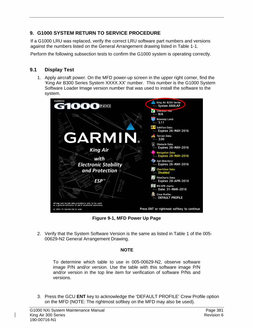
G1000 NXi System Maintenance Manual Page 381 King Air 300 Series Revision 6 190-00716-N1
9. G1000 SYSTEM RETURN TO SERVICE PROCEDURE If a G1000 LRU was replaced, verify the correct LRU software part numbers and versions against the numbers listed on the General Arrangement drawing listed in Table 1-1. Perform the following subsection tests to confirm the G1000 system is operating correctly.
9.1 Display Test 1. Apply aircraft power. On the MFD power-up screen in the upper right corner, find the
‘King Air B300 Series System XXXX.XX’ number. This number is the G1000 System Software Loader Image version number that was used to install the software to the system.
Figure 9-1, MFD Power Up Page
2. Verify that the System Software Version is the same as listed in Table 1 of the 005-
00629-N2 General Arrangement Drawing.
NOTE
To determine which table to use in 005-00629-N2, observe software image P/N and/or version. Use the table with this software image P/N and/or version in the top line item for verification of software P/Ns and versions.
3. Press the GCU ENT key to acknowledge the ‘DEFAULT PROFILE’ Crew Profile option
on the MFD (NOTE: The rightmost softkey on the MFD may also be used).

G1000 NXi System Maintenance Manual Page 382 King Air 300 Series Revision 6 190-00716-N1
Figure 9-2, PFD Power-up System Annunciations
4. Allow the displays to initialize for approximately one minute. During normal operation,
this causes the airspeed, altitude, vertical speed, and OAT fields to be invalid during the first ~40-60 seconds of PFD power-up. After two minutes, verify no Red-X’s are present on both PFDs and the MFD. Examples of potential Red-Xs are shown in Figure 9-2. If any Red-X’s are present, stop and troubleshoot per Section 5. Examples of PFDs with no Red-X failure indications are shown in Figure 9-3.

G1000 NXi System Maintenance Manual Page 383 King Air 300 Series Revision 6 190-00716-N1
(Without SVS enabled)
(With SVS enabled)
Figure 9-3, PFD Normal Operation

G1000 NXi System Maintenance Manual Page 384 King Air 300 Series Revision 6 190-00716-N1
NOTE
Outputs from the GRS 77/7800 or GSU 75B (AHRS portion) and GMU 44 are not valid until the units have been calibrated.
5. Check that all COM/NAV fields are valid in the top corners of PFD1 and PFD2. 6. Check that altitude, airspeed, vertical speed, GS, TAS, and OAT fields are valid on
PFD1 and PFD2. 7. Press the PFD Opt softkey on each PFD. 8. Press the SENSOR softkey followed by the ADC softkey on each PFD and switch
between ADC1 and ADC2. Verify that data from both GDC air data computers are valid on both displays.
9. Press the BACK softkey followed by the AHRS softkey on each PFD and switch between AHRS1 and AHRS2. Verify that data from both GRSs are valid on both displays.
10. Check that engine instrument fields are valid on the MFD. 11. Verify that no MANIFEST alert messages appear in the lower right corner (press the
flashing ALERTS softkey to view alert messages). If any MANIFEST errors appear, the correct software to the related LRU must be loaded before proceeding.
9.2 Display Failure Test
Step Desired Result
MFD Failure Condition: 1. Open MFD CB. 2. Verify desired results. 3. Close MFD CB.
For an MFD failure condition, the following shall occur: • MFD goes blank. • All PFD1 and PFD2 primary flight information is
retained. PFD1 enters reversion mode. • The COM 1/2 and NAV 1/2 tuning fields remain valid
and can be tuned by rotating the tuning knobs on PFD1 and PFD2.
• XPDR 1/2 fields remain valid and XPDRs can adjusted via PFD softkeys.
PFD2 Display Failure Condition: 1. Open PFD 2 CB. 2. Verify desired results. 3. Close PFD 2 CB.
For a PFD2 failure condition, the following shall occur: • PFD2 goes blank. • PFD1 and MFD remain in normal display formats. The
following illuminate on PFD1: o A white HDG box adjacent to the heading window o A white ROL box adjacent to the roll scale o A white PIT box adjacent to the pitch ladder o A white IAS box in the airspeed tape o A white ALT box in the altitude tape
• GMA2 Fail – GMA2 is inoperative. • XPDR2 Fail – XPDR2 is Inoperative.

G1000 NXi System Maintenance Manual Page 385 King Air 300 Series Revision 6 190-00716-N1
Step Desired Result
PFD1 Display Failure Condition: 1. Open PFD 1 PRI and PFD1 SEC circuit
breakers. 2. Verify desired results. 3. Close PFD 1 PRI and PFD1 SEC circuit
breakers.
For a PFD1 failure condition, the following shall occur: • PFD1 goes blank. • PFD2 and MFD remain in normal display formats. The
following illuminate on PFD2: o A white HDG box adjacent to the heading window o A white ROL box adjacent to the roll scale. o A white PIT box adjacent to the pitch ladder o A white IAS box in the airspeed tape o A white ALT box in the altitude tape
• GMA1 Fail – GMA1 is inoperative. • XPDR1 Fail – XPDR1 is Inoperative.
9.3 Reversion Mode Check 1. Push the red DISPLAY BACKUP button on GMA1. Verify that the pilot-side PFD and
MFD displays enter reversion mode (See Figure 9-4). MFD should have valid altitude, airspeed, vertical speed, COM 1, COM 2, NAV 1, NAV 2 and engine instruments.
Figure 9-4, GDU Reversionary Mode
2. De-activate pilot-side reversion mode by pushing the DISPLAY BACKUP button. Verify PFD1 and MFD return to normal display modes.

G1000 NXi System Maintenance Manual Page 386 King Air 300 Series Revision 6 190-00716-N1
3. Repeat Step 1 using GMA 2. Ensure that PFD 2 and MFD enter reversion mode and MFD displays valid altitude, airspeed, vertical speed, COM 1, COM 2, NAV 1, NAV 2 and engine instruments.
4. De-activate co-pilot’s side reversion mode by pushing the DISPLAY BACKUP button. Verify PFD 2 and MFD return to normal display modes.
9.4 Cooling Fan Fail Annunciation Check Do the following to verify the cooling fans and annunciations are functioning properly
Step Desired Result
Cooling Fan Failure Conditions: 1. Ensure the G1000 is in normal mode and verify
that there are no fan related alert messages displayed in the PFD1 or PFD2 Alerts Window.
2. Pull the following cooling fan circuit breakers: a) PFD/GIA FANS LEFT b) PFD/GIA FANS RIGHT c) MFD FAN
For the cooling fan failure conditions, after a 30-second delay verify that the following alert messages are displayed: • AVN FAN 1 FAIL – Avionics cooling fan #1 is
inoperative • AVN FAN 2 FAIL – Avionics cooling fan #2 is
inoperative • PFD 1 FAN FAIL – PFD #1 cooling fan is inoperative • PFD 2 FAN FAIL – PFD #2 cooling fan is inoperative • MFD FAN FAIL – MFD cooling fan is inoperative
Fan Failure reset and acknowledgement: 1. Reset all cooling fan circuit breakers. 2. Acknowledge alerts by pressing the Alerts
softkey on PFD1.
Verify the above alerts extinguish.
9.5 GPS Signal Acquisition This test requires the aircraft to be outside to see the GPS satellites or indoors with a GPS repeater.

G1000 NXi System Maintenance Manual Page 387 King Air 300 Series Revision 6 190-00716-N1
Figure 9-5, AUX-GPS Status Page
Select the AUX - GPS Status page on the MFD. After the G1000 system has been on for a minimum of two minutes, toggle between GPS 1 and GPS 2 using the two softkeys on the bottom of the display. Verify that both receivers show a 3D GPS Solution in the GPS Status field.
9.6 GPS Failure Test Before starting this test, create a simple Direct-To flight plan to an airport or other waypoint that is greater than 31 NM from the present aircraft position. Verify that the phase of flight displayed on the GPS CDI is ENR.
Step Desired Result
Single GPS Failure Condition: 1. Ensure GPS satellites are acquired. 2. Place a shroud over the GPS antenna for GIA 1
to prevent signal reception. Verify loss of signal on MFD Aux – GPS Status page.
3. Check for desired results. 4. Remove shroud from the GIA 1 GPS antenna
and allow system to re-acquire satellites. 5. Place a shroud over the GPS antenna for GIA 2
to prevent signal reception. Verify loss of signal on MFD Aux – GPS Status page.
6. Check for desired results. 7. Remove shroud from the GIA 2 GPS antenna.
For each of the single GPS failure conditions, the following shall remain valid on the PFD throughout the procedure:
• Attitude and Heading from AHRS. • Airspeed, Altitude, Vertical Speed, and OAT from Air
Data Computer. • GPS Course Deviation Indicator
For a GIA1 GPS Failure, an amber BOTH ON GPS2 is displayed on PFD 1 and PFD 2. For a GIA2 GPS Failure, an amber BOTH ON GPS1 is displayed on PFD 1 and PFD 2.

G1000 NXi System Maintenance Manual Page 388 King Air 300 Series Revision 6 190-00716-N1
Step Desired Result
Dual GPS Failure Condition: 1. Ensure GPS satellites are acquired. 2. Cover both GPS antennas. Verify loss of signal
on Aux – GPS Status page. 3. Check for desired results. 4. Remove shrouds from GPS antennas. 5. Allow both receivers to re-acquire satellite
signals before continuing.
For a dual GPS failure condition, the following shall occur: • GPS CDI flags LOI on both PFDs. • Attitude and Heading remain valid from both AHRS
on both PFDs. • Airspeed, Altitude, Vertical Speed and OAT remain
valid from both Air Data Computers on both PFDs. • LOI appears on MFD Map. • TAWS N/A aural alert & annunciation given.
When GPS satellites are re-acquired, verify that the INTEG OK annunciation is given on the HSI in white for a brief period of time then disappears.
After ~10 seconds of stable GPS position reacquisition, verify the TAWS AVAILABLE aural alert is given.
Verify that the system returns to normal navigation mode (GPS CDI restored, LOI annunciation removed, & GPS data magenta).

G1000 NXi System Maintenance Manual Page 389 King Air 300 Series Revision 6 190-00716-N1
9.7 GIA Failure Test
Step Desired Result
GIA 1 Failure Condition: 1. Ensure GPS satellites are acquired. 2. Open GIA1 primary and secondary CBs. 3. Verify desired results. 4. Close GIA1 primary and secondary CBs. Allow
system to re-acquire satellites and return to normal display modes.
For a GIA 1 failure condition, the following shall occur: • NAV 1 and COM 1 tuning fields on PFD1 and PFD2
are invalid (red X). • L/R engine data remains valid • XPDR 1 is Inoperative. (Not applicable to GTX 3x5R) • GMA 1 Is Inoperative. • AHRS 1 is using backup GPS source. • AHRS 2 not receiving backup GPS Information. • An amber BOTH ON GPS2 is displayed on PFD 1
and PFD2. • AHRS and ADC data remain valid on PFD 1 and PFD
2.
GIA 2 Failure Condition: 1. Open GIA 2 CB. 2. Verify desired results. 3. Close GIA 2 CB. Allow system to re-acquire
satellites and return to normal display modes.
For a GIA 2 failure condition, the following shall occur: • NAV 2 and COM 2 tuning fields on PFD 1 and PFD 2
are invalid (red X). • L/R engine data remains valid. • XPDR 2 is Inoperative. • GMA 2 Is Inoperative. • AHRS 2 is using backup GPS source. • AHRS 1 not receiving backup GPS Information. • An amber BOTH ON GPS1 is displayed on PFD 1
and PFD 2. • AHRS and ADC data remain valid on PFD 1 and PFD
2.
Dual GIA Failure Condition: 1. Open GIA 1 primary and secondary CBs and
GIA 2 CB. 2. Check for desired results. 3. Restore power to both GIA units.
For a dual GIA failure, the following shall occur: • COM 1/NAV 1 & COM 2/NAV 2 fields flag invalid. • GPS CDI flags LOI on PFD • NAV 1 & NAV 2 CDI loses deviation bar. • XPDR field flags invalid on PFD (Not applicable to
GTX 3x5R). • Engine Instrument field flags invalid on MFD. • All AHRS & ADC fields remain valid. • Red AFCS status annunciation given. • TAWS FAIL annunciation given. • ADF/DME windows flag invalid.*
*If equipped.
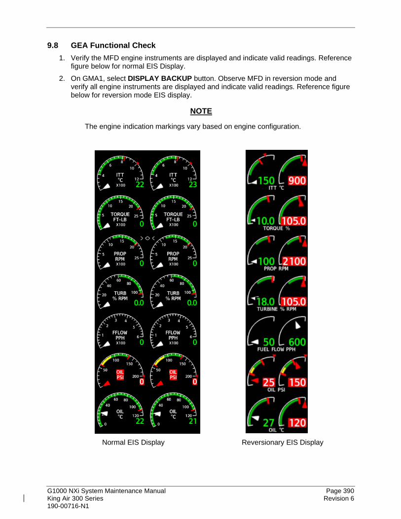
G1000 NXi System Maintenance Manual Page 390 King Air 300 Series Revision 6 190-00716-N1
9.8 GEA Functional Check 1. Verify the MFD engine instruments are displayed and indicate valid readings. Reference
figure below for normal EIS Display. 2. On GMA1, select DISPLAY BACKUP button. Observe MFD in reversion mode and
verify all engine instruments are displayed and indicate valid readings. Reference figure below for reversion mode EIS display.
NOTE
The engine indication markings vary based on engine configuration.
Normal EIS Display Reversionary EIS Display

G1000 NXi System Maintenance Manual Page 391 King Air 300 Series Revision 6 190-00716-N1
9.9 Standby Instrument Electrical Power Checks This section tests the standby electrical power for the standby MD 302 instrument or standby analog attitude indicator, standby altimeter, and the standby airspeed indicators. (The magnetic compass is tested in each Phase inspection during the cockpit lights check in the Beechcraft King Air 300 Series Maintenance Manual, listed in Table 1-1).
Step Desired Result
1. Remove or ensure external aircraft power is removed. Set main battery switch to OFF.
2. Ensure the STBY INSTR (or STBY ATT and STBY ALTM) circuit breaker(s) are closed.
3. Ensure the MASTER PANEL LIGHTS rocker switch in the overhead panel is in the ON position.
4. Ensure the STBY INSTR knob is turned to full bright.
Verify the STANDBY BATTERY annunciator/switch is not illuminated.
Select (depress) the STANDBY BATTERY switch. Verify the following: • For airplanes with MD 302 standby instrument installed.
o The MD 302 is activated, initializes, and displays an attitude indication of the top display and airspeed and altitude tapes on the bottom display.
o The MD 302 brightness has limited adjustment by rotating the knob on the bezel.
• For airplanes with analog standby instruments installed. o STBY Attitude indicator motor is energized as
indicated by the indicator motor and the absence of OFF flag.
o STBY altimeter vibrator is active as indicated by vibrator noise and absence of flag.
o STBY attitude, STBY Altimeter, STBY Airspeed indicators are illuminated full bright.
• Amber “ON” is annunciated full bright on the STANDBY BATTERY switch.
• White STANDBY BATTERY legend on the standby battery switch is illuminated full bright.

G1000 NXi System Maintenance Manual Page 392 King Air 300 Series Revision 6 190-00716-N1
Step Desired Result
Activate aircraft power by selecting the “on” position of the BATTERY switch.
Verify the following: • “ON” annunciation should extinguish on the STANDBY
BATTERY switch. • “ARM” should be fully illuminated (green) on the
STANDBY BATTERY switch. • White STANDBY BATTERY legend on the standby
battery switch remains illuminated. • For airplanes with MD 302 standby instrument installed.
o The MD 302 remains activated and displays an attitude indication of the top display and airspeed and altitude tapes on the bottom display.
o The MD 302 brightness may be fully adjusted by rotating the knob on the overhead panel.
• For airplanes with analog standby instruments installed. o The STBY attitude, STBY altimeter and STBY
airspeed instrument lighting reverts to the aircraft settings.
o The STBY attitude OFF flag not present and STBY altimeter vibrator remains active.
Deselect the STANDBY BATTERY switch Verify the following: • “ARM” annunciation extinguishes on the STANDBY
BATTERY switch. • White STANDBY BATTERY legend on the standby
battery switch remains illuminated. • For airplanes with MD 302 standby instrument installed.
o The MD 302 remains activated and displays an attitude indication of the top display and airspeed and altitude tapes on the bottom display.
o The MD 302 brightness may be adjusted by rotating the knob on the overhead panel.
• For airplanes with analog standby instruments installed. o STBY attitude OFF flag not present and
STBY altimeter vibrator remains active.
Remove aircraft power by selecting the battery switch to “OFF” position.
Verify the following: • White STANDBY BATTERY legend on the standby
battery switch extinguishes. • The magnetic compass is no longer illuminated. • For airplanes with MD 302 standby instrument installed.
o Both displays on the MD 302 are blank. • For airplanes with analog standby instruments installed.
o The STBY Attitude OFF flag is in view is deactivated (the sound of the motor may be present as the gyro spools down).
o The STBY altimeter vibrator is deactivated. o The STBY attitude, STBY altimeter, STBY
airspeed are no longer illuminated.
G1000 NXi System Maintenance Manual Page 393 King Air 300 Series Revision 6 190-00716-N1
9.10 G1000 Backup Path Test With all three displays in normal mode and the entire avionics system turned on, verify on PFD1 there is not a system alert message stating “Failed Data Path". If this message is present, troubleshoot per Section 5.1.1 and resolve the issue before continuing.
9.11 GFC 700 Ground Checkout The following procedures verify the proper operation of the GFC 700 AFCS, after maintenance has been performed. The technician performing these checks should be thoroughly familiar with the G1000 and GFC 700. Information on the installation and operation of the GFC 700 can be found by referring to Sections 6.12 and the G1000 King Air 300 Series Cockpit Reference Guide, listed in Table 1-2.
NOTE In the sections that follow, an Autopilot disconnect should be accompanied by an aural alert (two-second tone) unless otherwise specified.
9.11.1 Pre-Flight Test 1. Turn off the AVIONICS MASTER PWR, EXT PWR, and BATT switches and ground
power unit. After 30 seconds select the ground power unit, BATT, and EXT PWR switches to ON. Verify the GFC 700 begins an automatic pre-flight test after AHRS and ADC parameters become valid.
2. Verify that a white PFT annunciation is displayed on PFD1 and PFD2.
NOTE
A momentarily red annunciation displayed before PFT starts is acceptable.
3. Upon successful completion of the test, an aural alert will sound and the annunciation
will clear. The aural alert is generated by either GIA1 or GIA2, alternately, with each system power-up. Thus, the PFT sequence must be run twice to verify both GIA units are providing the correct aural alert.
NOTE If the ‘PFT’ annunciation turns red, the test has failed. Return to Section 5 for troubleshooting.
4. Repeat Steps 1 - 3 to test the PFT aural alert for the other GIA.
G1000 NXi System Maintenance Manual Page 394 King Air 300 Series Revision 6 190-00716-N1
9.11.2 AFCS Switch Checks Verify that the AFCS system buttons and switches are operating correctly by performing the following:
1. Actuate both sections of the PITCH TRIM (NOSE UP/NOSE DN) switch to activate Manual Electric Pitch Trim (MEPT). Verify the trim clutch engages and the trim wheel drives in the requested direction. Check operation in both the up and down direction.
2. Press the AP/YD DISC TRIM INTRPT switch and hold while actuating the manual electric trim switch. Verify trim does not run and the trim wheel rotates freely when moved manually. Release the AP/YD DISC TRIM INTRPT button and PITCH TRIM switch.
3. Engage the autopilot by pressing the AP key on AFCS mode controller. Press and hold the left section of the manual electric trim switch. Verify the Autopilot disengages normally with an aural alert and the trim wheel rotates freely when moved manually.
4. Engage the autopilot again by pressing the AP key on the AFCS mode controller. Verify the pitch and roll clutches engage and resist movement of the control wheel. Press and hold the CWS switch and verify the control wheel moves freely when moved manually. Verify the green ‘AP’ at the top of PFD 1 and PFD 2 is replaced by a white ‘CWS’.
5. Release the CWS switch and press the ‘XFR’ key on the AFCS mode controller. Verify the clutches are engaged and resist movement of the control wheel. Press and hold the CWS switch and verify the control wheel moves freely when moved manually. Verify the green ‘AP’ at the top of PFD 1 and PFD 2 is replaced by a white ‘CWS’.
6. Release the CWS switch and press the AP/YD DISC TRIM INTRPT switch on the pilots control wheel. Verify the autopilot disengages with a flashing amber ‘AP’ annunciation on PFD 1 and PFD 2, accompanied by an aural alert. Verify that the control wheel is free in pitch and roll axes.
7. Engage the autopilot again by pressing the ‘AP’ key on the AFCS mode controller. Open AFCS SERVOS circuit breaker. Verify the autopilot disconnects and the abnormal disconnect is provided, consisting of a continuous aural alert and a flashing red/white ‘AP’ annunciation. Verify no AFCS annunciations (e.g. AFCS, PFT, Mistrim) remain on PFD 1 or PFD 2. Press the AP/YD DISC TRIM INTRPT switch to cancel the abnormal alert. Close the AFCS SERVOS circuit breaker to restore power to the system and wait for completion of the pre-flight test sequence.
8. Engage the autopilot again by pressing the ‘AP’ key on the AFCS mode controller. Ensure the autopilot is coupled to GIA 1 by verifying the arrowhead next to the ‘XFR’ key on the AFCS mode controller is pointing to the pilot’s side. If the arrowhead points to the copilot’s side, press the ‘XFR’ key. Open GIA 1 primary and secondary circuit breakers. Verify the autopilot disconnects with a continuous aural alert and a flashing red/white ‘AP’ annunciation. Press the AP/YD DISC TRIM INTRPT switch to cancel the alert and annunciation. Close the GIA1 primary and secondary circuit breakers and wait for completion of the pre-flight test sequence.
9. Press the ‘XFR’ key on the AFCS mode controller and engage the autopilot by pressing the ‘AP’ key on the AFCS Mode Controller. Press the AP/YD DISC TRIM INTRPT switch on the pilot side to disconnect the autopilot; verify the flashing amber ‘AP’ alert is displayed on PFD 1 and PFD 2.
10. Press the GO AROUND button on the left throttle. Verify ‘TO’ is annunciated on PFD 1 and PFD 2 for both PITCH and ROLL modes and the command bars should be at 10 degrees nose up and wings-level.

G1000 NXi System Maintenance Manual Page 395 King Air 300 Series Revision 6 190-00716-N1
11. Press the Flight Director (FD) key on the AFCS mode controller to deactivate the GA mode. Press the AP key to engage the autopilot. Press the CWS button for a minimum of 5 seconds and release; verifying there is no residual force on the control stick for the pitch axis.
12. Disengage the autopilot by pressing the AP/YD DISC TRIM INTRPT switch on the co-pilot’s control wheel. Engage VS mode by pressing the VS key on the AFCS mode controller. Verify PFD 1 and PFD 2 display ‘VS’ in green and indicates a pitch reference of ‘0 FPM’.
13. Select an altitude using the ALT SEL knob on the AFCS mode controller. Press the FLC key on the AFCS mode controller and verify that ‘FLC’ is annunciated on PFD 1 and PFD 2 in green with a reference of 100 KTS.
14. Press the ALT key on the AFCS mode controller and verify that the ‘ALT’ annunciation is displayed in green on PFD 1 and PFD 2 with an altitude reference equal to the aircraft altitude (within the nearest 20 feet).
15. Press the FD key and verify that the mode annunciations and command bars are removed from the display.
9.11.3 Autopilot Clutch Overpower Check NOTE
The GFC 700 uses electronic torque limiting as well as mechanical slip clutches to limit the maximum servo effort. When the system is on the ground, the electronic torque limiting is removed, allowing manual checks of the slip-clutch settings.
1. Engage the Autopilot by pressing the AP key on the AFCS mode controller. 2. Manually overpower the autopilot clutches in pitch, roll and yaw. If the Autopilot clutches
cannot be overpowered, check the GSM 86 clutch cartridge. Refer to the servo installation drawing (listed in Table 1-1) as applicable.
3. Actuate and hold PITCH TRIM switch in either the NOSE UP or NOSE DOWN direction to disconnect the autopilot. While the trim is running, restrain the aircraft pitch trim wheel and verify that the trim clutch can be overpowered. If it cannot be overpowered, check the GSM 86 clutch cartridge. Refer to the pitch trim servo installation drawing listed in Table 1-1.
4. Engage the autopilot by pressing the AP key on the AFCS mode controller. Actuate and hold the manual electric trim switch in either the up or down direction to disconnect the autopilot. Verify that the trim wheel moves smoothly in both directions throughout the entire trim range during manual electric trim operation. If the trim wheel hesitates, this may indicate that the pitch trim clutch is slipping and proper clutch setting or clutch cartridge and cable tension should be verified. Refer to the King Air 300 Series Maintenance Manual and Pitch Trim Servo Install drawing, listed in Table 1-1, for clutch settings and cable tensions. If both clutch setting and cable tension are within tolerance, check the aircraft pitch trim system for excessive friction. Refer to the Beechcraft King Air 300 Series Maintenance Manual listed in Table 1-2.

G1000 NXi System Maintenance Manual Page 396 King Air 300 Series Revision 6 190-00716-N1
9.11.4 Manual Electric Pitch Trim Speed Check 1. Run MANUAL ELECTRIC PITCH TRIM in one direction until it runs against the
mechanical stop. 2. Run the trim in the opposite direction, and using a stop watch or equivalent device, time
the trim speed to the opposite mechanical stop. Verify the elapsed time for full travel measures 13 ± 3 seconds.
9.11.5 Autopilot Operation Checks 1. Engage the Autopilot by pressing the AP key on the AFCS mode controller. Push the
HDG knob to synchronize the heading bug to the current aircraft heading. Select HDG mode by pressing the HDG key on the AFCS mode controller. Verify the command bars are level and the control wheel is stationary. (There may be some roll motion in the yoke if the aircraft not perfectly level.)
2. Turn the HDG knob to the left and right and check that the command bars move in the correct direction and the control wheel follows the command bars.
3. Push and hold the CWS button and pull the control wheel to the center of the pitch control range. Release the CWS button. Verify the autopilot clutches re-engage and hold the wheel stationary.
4. Holding the control wheel lightly, rotate the NOSE UP/DN wheel on the AFCS mode controller two clicks UP to increase the pitch reference. Verify the command bars move up 1 degree and the control wheel begins moving aft. (In some aircraft, the down spring may require manual assistance to get aft control stick movement).
5. While holding the control wheel firmly, press and hold the CWS button to re-synchronize the pitch reference. Re-center the control wheel to wings level and mid-range elevator travel. Release the CWS button and check that servo clutches re-engage before releasing the control wheel.
6. Rotate the NOSE UP/DN wheel on the AFCS mode controller two clicks DOWN to decrease the pitch reference. Verify the command bars move down 1 degree and the control wheel begins moving forward. Hold the controls and press CWS to re-center the command bars and stop control wheel movement.
7. With the Autopilot still engaged and the CWS button pressed, move the control wheel to its aft limit. Release the CWS button and apply continuous forward pressure, slowly moving the control wheel. After a brief delay, verify the trim wheel begins moving in a trim up direction.
8. Grip the control wheel and press the CWS button. Verify trim motion stops. Move the control wheel to the forward limit and release the CWS button. Slowly move the control wheel aft. After a brief delay, verify the trim wheel begins to trim down. Relieve pressure on the wheel and verify the trim motion stops. Check that the trim wheel is free to turn. Hold the control wheel and press the AP/YD DISC TRIM INTRPT switch to disconnect the autopilot.

G1000 NXi System Maintenance Manual Page 397 King Air 300 Series Revision 6 190-00716-N1
9.11.6 VOR/LOC/GS Test Perform the following test using ramp test equipment. Operate the equipment according to the test equipment manufacturer’s instructions.
NOTE The PFD HSI does not show a course deviation bar unless a valid VHF NAV frequency is tuned.
1. Ensure FD is coupled to PFD 1 as indicated by a left pointing arrow next to the XFR button.
2. Simulate a VOR signal on a radial equivalent to the aircraft heading. Tune the NAV 1 and NAV 2 receivers to the simulation frequency.
3. Set the HSI on PFD 1 to VOR1 by pressing the CDI softkey until VOR1 is selected. Set the HSI on PFD 2 to VOR2 by pressing the CDI softkey until VOR2 is selected. Rotate CRS1 and CRS2 knobs to set VOR1 and VOR2 course pointers to aircraft heading. (CDI Synchronization must be set to OFF on the Aux – System Setup 1 page on the MFD.)
4. Verify full scale deflection of VOR1 and VOR2 CDI by varying the selected course at least 10° left and right. Reset course pointers to aircraft heading.
5. Engage the autopilot and press the NAV key on the AFCS mode controller. Using the CRS1 knob alter course by 10° to the right. Verify the flight director and aircraft controls respond by flying to the VOR course. Repeat to the left.
6. Couple FD to PFD2 by pressing the XFR button on the AFCS mode controller. Verify FD is coupled right as indicated by a right pointing arrow on the AFCS mode controller next to the XFR button. Repeat step 5 using CRS2 knob while coupled to PFD2.
7. Set CRS1 and CRS2 course pointers to aircraft heading. 8. Simulate a Localizer/Glideslope signal. Tune this signal on NAV 1 and NAV 2 receiver.
Set the PFD 1 HSI to LOC1 and PFD 2 HSI to LOC2 by pressing CDI softkey until LOC1 and LOC2 is selected. Use the test equipment to center the deviation bars (localizer and glideslope) on PFD1 and PFD2.
9. Press the APR key on the AFCS mode controller. Verify that the LOC and GS annunciations are green on PFD 1 and PFD 2. Apply right/left and up/down localizer/glideslope signals using the test equipment. Verify that the Flight Director and flight controls respond appropriately.
10. Couple FD to PFD 1 by pressing the XFR button on the AFCS mode controller. Verify FD is coupled to PFD 1 as indicated by a left pointing arrow on the AFCS mode controller next to the XFR button.
11. Repeat step 9 while coupled to PFD 1.

G1000 NXi System Maintenance Manual Page 398 King Air 300 Series Revision 6 190-00716-N1
9.12 Maintenance Records The Configuration Checklist in Section 3.6 should be completed when a Service Bulletin software update has been performed and maintained with the aircraft permanent records. Record the following information:
• Part number of the G1000 software loader card used to perform software loading or software updates.
• Record part and serial numbers of any LRU which was replaced.
• Record any database updates which were performed during maintenance.
• Any other applicable information related to the maintenance work performed on the aircraft.

G1000 NXi System Maintenance Manual Page A-1 King Air 300 Series Revision 6 190-00716-N1
APPENDIX A - Garmin Unit Part and Serial Number Cross Reference This table allows shows the unit part number and serial number prefix combinations.
LRU PART NUMBER SERIAL NUMBER FIRST THREE DIGITS
GIA 63W 011-01105-20 1HQ GIA 64E 011-03711-40 4SM GDU 1050A (PFD 1 & PFD 2) 011-03470-10 494 GDU 1550 (MFD) 011-03472-00 496 GMA 1347D 011-01257-20 171 GMA 1360D 011-03568-20 4QF GEA 71 011-00831-00 467 GEA 71B 011-03682-02 499
GDC 7400 (OPTIONAL) 011-02337-00 1U60 011-02337-01 1U61
GRS 77 (LEGACY) 011-00868-10 420
GRS 7800 (OPTIONAL) 011-02278-00 25M 011-02278-01 4DK
GMU 44 011-00870-10 1CM 011-00870-20 39Z
GSU 75B 011-03094-40 4E4 GTX 33 (LEGACY) 011-00779-30 891 GTX 33D (OPTIONAL) 011-00779-21 848 GTX 3000 (OPTIONAL) 011-01997-00 20S GTX 335R (OPTIONAL) 011-03301-00 3EF GTX 345R (OPTIONAL) 011-03303-00 3EH
GCU 477 011-01428-00 194 011-01428-20 48Y
GMC 710 011-01020-10 220 GDL 59 011-01746-00 1EJ GDL 69A (LEGACY) 011-00987-00 477 GDL 69 SXM 011-03177-10 3NV GSD 41 011-01457-00 169 GWX 68 011-00883-20 472 GWX 70 011-01768-00 1DP GWX 75 010-01590-00 4RR GSA 80 PITCH SERVO 011-00877-20 19Z GSA 80 ROLL SERVO 011-00877-20 19Z
GSA 9000 YAW SERVO 011-02213-00 1R9 011-02213-10 2JL
GSA 80 PITCH TRIM SERVO 011-00877-21 1A0 GTS PROCESSOR (OPTIONAL) 011-02571-00 28P GTS 820 TAS (OPTIONAL) 011-01446-00 1EA GTS 850 TCAS I (OPTIONAL) 011-01553-00 1EB GRA 5500 011-02537-00 2F8 FLIGHT STREAM 510 (OPTIONAL) 011-03595-00 402