g.8275.2 telecom profile - cisco.com · configuring theg.8275.2 profile...
TRANSCRIPT
G.8275.2 Telecom Profile
Precision Time Protocol (PTP) is a protocol for distributing precise time and frequency over packet networks.PTP is defined in the IEEE Standard 1588. It defines an exchange of timed messages.
PTP allows for separate profiles to be defined in order to adapt PTP for use in different scenarios. A profileis a specific selection of PTP configuration options that are selected to meet the requirements of a particularapplication.
Effective Cisco IOS XE Everest 16.5.1, Cisco ASR 920 routers support the ITU- T G.8275.2 telecom profile(PTP telecom profile for Phase/Time-of-day synchronization with partial timing support from the network).
The G.8275.2 is a PTP profile for use in telecom networks where phase or time-of-day synchronization isrequired. It differs from G.8275.1 in that it is not required that each device in the network participates in thePTP protocol. Also, G.8275.2 uses PTP over IPv4 and IPv6 in unicast mode. However, IPv6 is not supportedin Cisco IOS XE Everest 16.5.1.
In this document, G.8275.2 refers to ITU-T G.8275.2 (02/2016).Note
• Why G.8275.2?, on page 1• Benefits, on page 5• Restrictions for Using the G.8275.2 Profile, on page 5• Configuring the G.8275.2 Profile, on page 5• G.8275.2 Deployment Scenario, on page 11• Additional References, on page 12• Feature Information for G.8275.2, on page 13
Why G.8275.2?The G.8275.2 profile is based on the partial timing support from the network. Hence nodes using G.8275.2are not required to be directly connected.
The G.8275.2 profile is used in mobile cellular systems that require accurate synchronization of time andphase. For example, the fourth generation (4G) of mobile telecommunications technology.
G.8275.2 Telecom Profile1
PTP ClocksTwo types of ordinary clocks and three types of boundary clocks are used in this profile:
Ordinary Clocks (OCs)
• TelecomGrandmaster (T-GM): A telecom grandmaster provides timing for other devices in the network,and is usually connected to a primary reference time source, such as a GNSS receiver. It does notsynchronize its local clock to other network elements.
Considerations for a T-GM:
• Only one PTP port can be configured as a master port.
• One T-GM master port can have multiple slaves associated with it.
• The T-GM OC Master port is a fixed port; that is, it always acts as a master clock and its role doesnot change by negotiating with its peer.
• Partial-Support Telecom Time Slave Clocks (T-TSC-P): A slave clock synchronizes its local clockto another PTP clock (GM, T-GM or T-BC), and does not provide synchronization through PTP to anyother device.
Considerations for a T-TSC-P:
• An ordinary clock with single slave port can be configured.
• Only one peer clock address can be configured as clock source.
Boundary Clocks (BCs)
Boundary clocks can assume any of the following roles:
• A BC that can only be a grandmaster (T-GM)
A master-only boundary clock can have multiple master port configured. The different master ports canbe in different VLANs to serve the slaves that need to be served over them.
• A BC that can become a grandmaster and can also be a slave to another PTP clock (T-BC-P).
Slave-only port configuration is not allowed under boundary clocks. However, one of the dynamic ports(port state negotiated based on BMCA), can assume the role of slave.
• A BC that can only be a slave (T-TSC-P with more than one port).
Fixed master port, dynamic ports and virtual port can be configured under a boundary clock. However, onlyone clock source (peer address) can be configured with a dynamic port.
Miscellaneous Notes
• Any clock that has multiple PTP ports within a PTP domain is termed a boundary clock (BC). Ordinaryclocks (OC) always have only one PTP port.
In G.8275.2 (02/2016), PTP transparent clocks are not permitted.
G.8275.2 Telecom Profile2
G.8275.2 Telecom ProfilePTP Clocks

PTP DomainA PTP domain is a logical grouping of clocks that communicate with each other using the PTP protocol.
A single computer network can have multiple PTP domains operating separately, for example, one set ofclocks synchronized to one time scale and another set of clocks synchronized to another time scale. PTP canrun over either Ethernet or IP, so a domain can correspond to a local area network or it can extend across awide area network.
The allowed domain numbers of PTP domains within a G.8275.2 network are in the range of 44 and 63 (bothinclusive). The default domain number is 44.
PTP Messages and TransportThe following PTP transport parameters are defined:
• In Cisco IOS XE Everest 16.5.1, PTP over IPv4 in unicast mode must be used..
• Either one-step or two-step clock mode must be used.
• For PTP master clock, both one-way and two-way operation modes are supported. This means PTPmaster can grant request to a slave's one-way or two-way requests.
• In case of PTP slave clock, two-way PTP operation is required to allow phase/time-of-day delivery. Thedelay-request-response mechanism is used to propagate delay measurement; the peer-delay mechanismis not used.
• The G.8275.2 profile supports unicast message negotiation.
• Interfaces carrying PTP traffic can be under different VRFs.
• Sync, Delay_Req, Announce, Follow_Up, Delay_Resp, and Signaling messages are used in this profile.See the table below for rates of transmission for these messages.
Table 1: PTP Messages and their Rate of Transmission
MaximumRate (packetsper second)
Minimum Rate(packets per second)
Default Rate (packetsper second)
Message
128132Sync
128132Follow_up (only if syncmessages are used)
128116Delay_Req
128116Delay_Resp
811Announce
Not specified1Not SpecifiedSignaling
G.8275.2 Telecom Profile3
G.8275.2 Telecom ProfilePTP Domain

Limitations
• Pdelay_Req, Pdelay_Resp, Pdelay_Resp_Follow_Up and management messages are not used in thisprofile.
PTP PortsA port can be configured to perform either fixed master or slave role or can be configured to change its roledynamically. If no role is assigned to a port, it can dynamically assume a master, passive, or slave role basedon the BMCA.
In G.8275.2, PTP ports are not tied to any specific physical interfaces, but are tied to a loopback (virtual)interface. Traffic from a PTP port is routed through any physical interface based on the routing decision.
For a Boundary Clock, multiple PTP ports are supported. The maximum number of PTP ports supported ona BC node is 64.
For a dynamic port, only one clock source can be configured.
Virtual Port Support on T-BCIn G.8275.2 implementation, virtual PTP ports are used to provide electrical frequency and phase inputs toT-BC. With virtual ports, T-BCs are fed with frequency inputs, such as, synchronous Ethernet, 10M, BITS,and phase/time inputs, such as, 1PPS and ToD. Virtual ports participate in the BMCA algorithm of the T-BCs.
If frequency source is of Category-1 (according to G.8275.2) and if 1PPS and ToD inputs are UP, virtual portstatus is up. Otherwise, virtual port status is down.
A virtual port participates in BMCA only when it is in administratively up state.
A virtual port always has clock class 6, clock accuracy 0x21 (within 100ns), and clock offset Scaled LogVariance of 0x4E5D.
The virtual port has the attributes set to the above values only when it is in the UP state.Note
Whenever virtual port is selected as the best master by the BMCA, PTP clock is driven by the electrical inputs.If virtual port is administratively up but not selected by BMCA, 1PPS and ToD inputs do not affect PTP clock.
Alternate BMCAThe BMCA implementation in G.8275.2 is different from that in the default PTP profile. The G.8275.2implementation specifies an alternate best master clock algorithm (ABMCA), which is used by each deviceto select a clock to synchronize to, and to decide the port states of its local ports.
The following consideration apply to the G.8275.2 implementation of the BMCA:
• MasterOnly: A per port attribute, MasterOnly defines the state of the port. If this attribute is true, theport is never placed in the Slave state.
• Priority 1: Priority 1 is always static in this profile and is set to 128. Priority 1 is not used in BMCA.
• Priority 2: Priority 2 is a configurable value and its range if from 0 to 255.
G.8275.2 Telecom Profile4
G.8275.2 Telecom ProfilePTP Ports

• Local Priority: Local priority is configured locally on clock ports to set the priority on nominated clocks.The default value is 128 and valid range is from 1 to 255.
BenefitsWith upcoming technologies like LTE-TDD, LTE-A CoMP, LTE-MBSFN and Location-based services,eNodeBs (base station devices) are required to be accurately synchronized in phase and time. Having GNSSsystems at each node is not only expensive, but also introduces vulnerabilities. The G.8275.2 profile meetsthe synchronization requirements of these new technologies.
Restrictions for Using the G.8275.2 Profile• In G.8275.2, PTP can be used in both hybrid mode and non-hybrid mode. In hybrid mode, PTP is usedto provide phase and time-of-day throughout the network synchronization alongwith PHY layer frequencysupport (SyncE). In non-hybrid mode, PTP is used without PHY layer frequency support (SyncE).
• A G.8275.2 PTP clock can have redundant clock sources configured (through multiple PTP ports).However, at any given time, a G.8275.2 PTP clock synchronizes to only one clock source, which isselected by BMCA.
• In Cisco IOS XE Everest 16.5.1, the G.8275.2 does not support assisted partial-support telecom timeslave clock (T-TSC-A).
• The G.8275.2 does not provide any recommendations for performance analysis and network limits forthe clocks.
• Effective Cisco IOS XE Everest 16.5.1, only one loopback address can be associated with all PTP ports.
Configuring the G.8275.2 Profile
To know more about the commands referenced in this module, see the Cisco IOS Interface and HardwareComponent Command Reference or the Cisco IOS Master Command List.
Note
Configuring Physical Frequency SourceFor more information, see the Configuring Synchronous Ethernet ESMC and SSM section in the Clockingand Timing chapter of this book.
Creating a Master-OnlyT-GM Ordinary Clock
ptp clock ordinary domain 44
G.8275.2 Telecom Profile5
G.8275.2 Telecom ProfileBenefits

clock-port master1 master profile g8275.2transport ipv4 unicast interface Loopback0 negotiation
T-GM Boundary Clock
A boundary clock can be configured as a T-GM by configuring the external inputs of 10m, 1pps and ToD.However, external inputs to a boundary clock can be given only through a virtual port.ptp clock boundary domain 44 hybridvirtual-port vp1 profile g8275.2input 1pps R0input tod R0 ntpclock-port dp2transport ipv4 unicast interface Loopback0 negotiationclock source 60.60.60.60
ptp clock boundary domain 45clock-port d1 profile g8275.2 local-priority 12transport ipv4 unicast interface Lo0 negotiationclock source 1.1.1.1clock-port dp2 profile g8275.2 local-priority 13transport ipv4 unicast interface Lo0 negotiationclock source 12.12.12.12clock-port dp3 profile g8275.2 local-priority 14transport ipv4 unicast interface Lo0 negotiationclock source 56.56.56.56clock-port dp1 profile g8275.2 local-priority 12transport ipv4 unicast interface Lo0 negotiationclock source 2.2.2.2
Creating an Ordinary Slave (T-TSC-P)ptp clock ordinary domain 44clock-port slave-port slave profile G.8275.2transport ipv4 unicast interface lo 0 negotiationclock source 1.1.1.1
Creating a Boundary Clockptp clock boundary domain 44clock-port master-port-1 master profile G.8275.2transport ipv4 unicast interface lo 0 negotiation
clock-port port1 profile G.8275.2transport ipv4 unicast interface lo 0 negotiationclock source 1.1.1.1
clock-port port2 profile G.8275.2transport ipv4 unicast interface lo 0 negotiationclock source 1.1.1.2
Creating Dynamic PortsThe following considerations apply to dynamic ports:
• Dynamic ports are created by not specifying whether a port is master or slave. In such cases, the BMCAdynamically choses the role of the port.
• Dynamic ports do not have a keyword.
• All the dyanamic ports configured under a clock must use the same loopback interface.
G.8275.2 Telecom Profile6
G.8275.2 Telecom ProfileCreating an Ordinary Slave (T-TSC-P)

• For a dynamic port to communicate with a peer, it must have clock source x.x.x.x configured with it.
ptp clock boundary domain 44 hybridutc-offset 45 leap-second “01-01-2017 00:00:00” offset 1clock-port bc-port-1 profile g8275.2local-priority 1transport ipv4 unicast interface Lo0 negotiationclock source 1.1.1.1clock-port bc-port-2 profile g8275.2 local-priority 2transport ipv4 unicast interface Lo0 negotiationclock source 2.2.2.2
Configuring Virtual Ports
ptp clock boundary domain 44 hybridutc-offset 37 leap-second “01-01-2017 00:00:00” offset 1virtual-port virtual-port-1 profile g8275.2 local-priority 1input 1pps R0input tod R0 ntp
Restrictions for Configuring Virtual Ports• Virtual port configuration is not allowed under Ordinary Clocks.• Virtual port configuration is not supported under non-hybrid T-BC cases.
Verifying the Default and Parent Datasets
Router# show ptp clock dataset default
CLOCK [Boundary Clock, domain 44]
Two Step Flag: No
Clock Identity: 0x5C:83:8F:FF:FE:1F:27:BF
Number Of Ports: 5
Priority1: 128
Priority2: 128
Local Priority: 128
Domain Number: 44
Slave Only: No
Signal Fail: No
Clock Quality:
Class: 165
Accuracy: Unknown
Offset (log variance): 65535
G.8275.2 Telecom Profile7
G.8275.2 Telecom ProfileConfiguring Virtual Ports
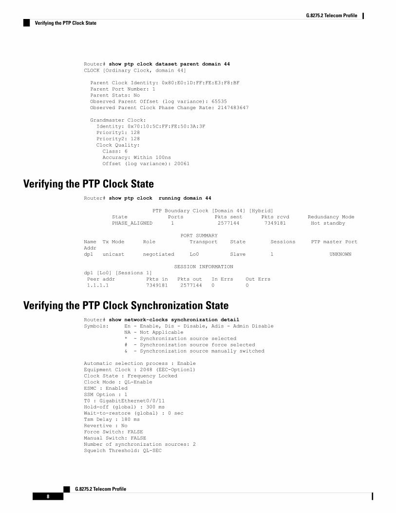
Router# show ptp clock dataset parent domain 44CLOCK [Ordinary Clock, domain 44]
Parent Clock Identity: 0x80:E0:1D:FF:FE:E3:F8:BFParent Port Number: 1Parent Stats: NoObserved Parent Offset (log variance): 65535Observed Parent Clock Phase Change Rate: 2147483647
Grandmaster Clock:Identity: 0x70:10:5C:FF:FE:50:3A:3FPriority1: 128Priority2: 128Clock Quality:Class: 6Accuracy: Within 100nsOffset (log variance): 20061
Verifying the PTP Clock StateRouter# show ptp clock running domain 44
PTP Boundary Clock [Domain 44] [Hybrid]State Ports Pkts sent Pkts rcvd Redundancy ModePHASE_ALIGNED 1 2577144 7349181 Hot standby
PORT SUMMARYName Tx Mode Role Transport State Sessions PTP master PortAddrdp1 unicast negotiated Lo0 Slave 1 UNKNOWN
SESSION INFORMATIONdp1 [Lo0] [Sessions 1]Peer addr Pkts in Pkts out In Errs Out Errs1.1.1.1 7349181 2577144 0 0
Verifying the PTP Clock Synchronization StateRouter# show network-clocks synchronization detailSymbols: En - Enable, Dis - Disable, Adis - Admin Disable
NA - Not Applicable* - Synchronization source selected# - Synchronization source force selected& - Synchronization source manually switched
Automatic selection process : EnableEquipment Clock : 2048 (EEC-Option1)Clock State : Frequency LockedClock Mode : QL-EnableESMC : EnabledSSM Option : 1T0 : GigabitEthernet0/0/11Hold-off (global) : 300 msWait-to-restore (global) : 0 secTsm Delay : 180 msRevertive : NoForce Switch: FALSEManual Switch: FALSENumber of synchronization sources: 2Squelch Threshold: QL-SEC
G.8275.2 Telecom Profile8
G.8275.2 Telecom ProfileVerifying the PTP Clock State

sm(netsync NETCLK_QL_ENABLE), running yes, state 1ALast transition recorded: (sf_change)-> 1A (sf_change)-> 1A (sf_change)-> 1A (sf_change)->1A (sf_change)-> 1A (sf_change)-> 1A (sf_change)-> 1A (ql_change)-> 1A (sf_change)-> 1A(ql_change)-> 1A
Nominated Interfaces
Interface SigType Mode/QL Prio QL_IN ESMC Tx ESMC RxInternal NA NA/Dis 251 QL-SEC NA NA*Gi0/0/11 NA Sync/En 1 QL-PRC - -Te0/0/24 NA Sync/En 2 QL-PRC - -
Interface:---------------------------------------------Local Interface: InternalSignal Type: NAMode: NA(Ql-enabled)SSM Tx: DISABLEDSSM Rx: DISABLEDPriority: 251QL Receive: QL-SECQL Receive Configured: -QL Receive Overrided: -QL Transmit: -QL Transmit Configured: -Hold-off: 0Wait-to-restore: 0Lock Out: FALSESignal Fail: FALSEAlarms: FALSEActive Alarms: NoneSlot Disabled: FALSESNMP input source index: 1SNMP parent list index: 0Description: None
Local Interface: Gi0/0/11Signal Type: NAMode: Synchronous(Ql-enabled)ESMC Tx: ENABLEDESMC Rx: ENABLEDPriority: 1QL Receive: QL-PRCQL Receive Configured: -QL Receive Overrided: -QL Transmit: QL-DNUQL Transmit Configured: -Hold-off: 300Wait-to-restore: 0Lock Out: FALSESignal Fail: FALSEAlarms: FALSEActive Alarms : NoneSlot Disabled: FALSESNMP input source index: 2SNMP parent list index: 0Description: None
Local Interface: Te0/0/24Signal Type: NAMode: Synchronous(Ql-enabled)ESMC Tx: ENABLEDESMC Rx: ENABLED
G.8275.2 Telecom Profile9
G.8275.2 Telecom ProfileVerifying the PTP Clock Synchronization State

Priority: 2QL Receive: QL-PRCQL Receive Configured: -QL Receive Overrided: -QL Transmit: QL-PRCQL Transmit Configured: -Hold-off: 300Wait-to-restore: 0Lock Out: FALSESignal Fail: FALSEAlarms: FALSEActive Alarms : NoneSlot Disabled: FALSESNMP input source index: 3SNMP parent list index: 0Description: None
Verifying the Port Parameters
Router# show ptp port dataset port domain 44
PORT [MASTER-1]Clock Identity: 0x70:10:5C:FF:FE:50:3A:3FPort Number: 1Port State: MasterMin Delay Req Interval (log base 2): -4Peer Mean Path Delay: 0Announce interval (log base 2): 1Announce Receipt Timeout: 3Sync Interval (log base 2): -5Delay Mechanism: End to EndPeer Delay Request Interval (log base 2): -4PTP version: 2Local Priority: 128Master-only: TrueSignal-fail: False
Verifying the Foreign Master Information
Router# show platform software ptp foreign-master domain 44PTPd Foreign Master Information:
Current Master: SLA
Port: SLAGM Clock Identity: 0x70:10:5C:FF:FE:50:3A:3FClock Stream Id: 0Priority1: 128Priority2: 128Local Priority: 10Clock Quality:Class: 6Accuracy: Within 100nsOffset (Log Variance): 0x4E5DSource Port Identity:Clock Identity: 0x70:10:5C:FF:FE:50:3A:3FPort Number: 1Steps Removed: 1
G.8275.2 Telecom Profile10
G.8275.2 Telecom ProfileVerifying the Port Parameters

masterOnly: FALSEQualified: TRUE
Verifying Current PTP Time
Router# show platform software ptpd todPTPd ToD information:
Time: 01/05/70 06:40:59
Verifying the Virtual Port Status
Router# show ptp port virtual domain 44
VIRTUAL PORT [vp1]Status: upClock Identity: 0x64:F6:9D:FF:FE:F2:25:3FPort Number: 2Clock Quality:Class: 6Accuracy: 0x21Offset (log variance): 0x4E5D
Steps Removed: 0Priority1: 128Priority2: 128Local Priority: 128Not-slave: FalseSignal-fail: True
G.8275.2 Deployment ScenarioThe following example illustrates a possible configuration for a G.8275.2 network with twomasters, a boundaryclock and a slave. Let’s assume that master A is theordinary clock and B is the backup master with virtualport.Figure 1: Topology for a Configuration Example
The configuration on TGM A (as ordinary clock):
ptp clock ordinary domain 44tod R0 ntp
G.8275.2 Telecom Profile11
G.8275.2 Telecom ProfileVerifying Current PTP Time

input 1pps R0utc-offset 37clock-port master master profile g8275.2transport ipv4 unicast interface Lo0 negotiation
The configuration on TGM B with Virtual Port:
ptp clock boundary domain 44 hybridutc-offset 37clock-port dynamic1 profile g8275.2transport ipv4 unicast interface Lo0 negotiationclock source 3.3.3.3virtual-port virtual1 profile g8275.2input 1pps R0input tod R0 ntp
The configuration on the boundary clock:
ptp clock boundary domain 44 hybridclock-port dynamic1 profile g8275.2 local-priority 1transport ipv4 unicast interface Lo0 negotiationclock source 1.1.1.1clock-port dynamic2 profile g8275.2 local-priority 2transport ipv4 unicast interface Lo0 negotiationclock source 2.2.2.2clock-port dynamic3 profile g8275.2transport ipv4 unicast interface Lo0 negotiationclock source 4.4.4.4
The configuration on the slave clock:
ptp clock ordinary domain 44 hybridclock-port slave slavetransport ipv4 unicast interface Lo0 negotiationclock source 3.3.3.3
Additional ReferencesRelated Documents
Document TitleRelated Topic
Cisco IOS Master Commands List, All ReleasesCisco IOS commands
Cisco IOS Interface and Hardware Component CommandReference
Interface and Hardware Component commands
Clocking and TimingClocking and Timing
Standards
TitleStandard
Precision time protocol telecom profile for time/phase synchronization withpartial timing support from the network
G.8275.2/Y.1369.2(06/16)
G.8275.2 Telecom Profile12
G.8275.2 Telecom ProfileAdditional References

MIBs
MIBs LinkMIB
To locate and download MIBs for selected platforms, Cisco software releases, and feature sets, useCisco MIB Locator found at the following URL:
http://www.cisco.com/go/mibs
—
RFCs
TitleRFC
There are no new RFCs for this feature.—
Feature Information for G.8275.2Use Cisco Feature Navigator to find information about platform support and software image support. CiscoFeature Navigator enables you to determine which software images support a specific software release, featureset, or platform. To access Cisco Feature Navigator, go to http://www.cisco.com/go/cfn . An account onCisco.com is not required.
Table 2: Feature Information for G.8275.2
Feature InformationReleaseFeatureName
This PTP telecom profile introduces phase and time synchronization with partialsupport from the network.
16.5.1G.8275.2
G.8275.2 Telecom Profile13
G.8275.2 Telecom ProfileFeature Information for G.8275.2

G.8275.2 Telecom Profile14
G.8275.2 Telecom ProfileFeature Information for G.8275.2