gamma-ray large telescope anticoincidence detector … · glast lat project cdr/cd-3 review may ......
TRANSCRIPT
GLAST LAT Project CDR/CD-3 Review May 12-16, 2003
Document: LAT-PR-01967 Section 11 ACD Subsystem 1
GLAST Large Area Telescope:GLAST Large Area Telescope:
AntiCoincidence Detector (ACD)SubsystemWBS: 4.1.6
David J. ThompsonThomas E. JohnsonNASA Goddard Space Flight CenterSubsystem Manager/Instrument Manager
[email protected]@nasa.gov
Gamma-ray LargeGamma-ray LargeArea SpaceArea SpaceTelescopeTelescope

GLAST LAT Project CDR/CD-3 Review May 12-16, 2003
Document: LAT-PR-01967 Section 11 ACD Subsystem 2
OverviewOverview
Section 11-1Section 11-1
Gamma-ray LargeGamma-ray LargeArea SpaceArea SpaceTelescopeTelescope
GLAST LAT Project CDR/CD-3 Review May 12-16, 2003
Document: LAT-PR-01967 Section 11 ACD Subsystem 3
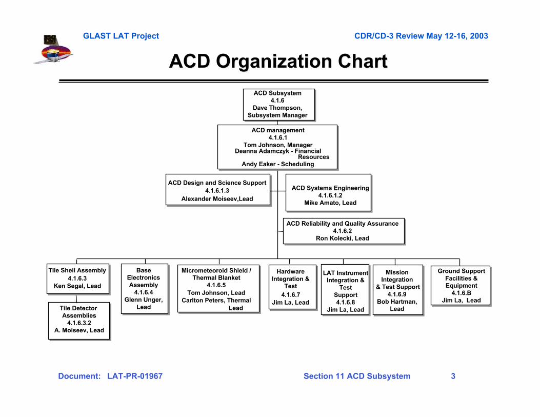
ACD Organization ChartACD Organization Chart
ACD Systems Engineering4.1.6.1.2
Mike Amato, Lead
Tile Shell Assembly4.1.6.3
Ken Segal, Lead
BaseElectronicsAssembly
4.1.6.4Glenn Unger,
Lead
Micrometeoroid Shield /Thermal Blanket
4.1.6.5Tom Johnson, Lead
Carlton Peters, Thermal Lead
ACD Design and Science Support4.1.6.1.3
Alexander Moiseev,Lead
Tile Detector Assemblies
4.1.6.3.2A. Moiseev, Lead
ACD Reliability and Quality Assurance4.1.6.2
Ron Kolecki, Lead
HardwareIntegration &
Test4.1.6.7
Jim La, Lead
MissionIntegration
& Test Support4.1.6.9
Bob Hartman,Lead
Ground SupportFacilities &Equipment
4.1.6.BJim La, Lead
LAT InstrumentIntegration &
TestSupport4.1.6.8
Jim La, Lead
ACD management4.1.6.1
Tom Johnson, ManagerDeanna Adamczyk - Financial
ResourcesAndy Eaker - Scheduling
ACD Subsystem4.1.6
Dave Thompson,Subsystem Manager
GLAST LAT Project CDR/CD-3 Review May 12-16, 2003
Document: LAT-PR-01967 Section 11 ACD Subsystem 4
ACD Team PartnersACD Team Partners
– Micrometeoroid Shield Design – Johnson Space Center
• NASA Center of Excellence for micrometeoroid protection
• Eric Christiansen and Jeanne Crews
– Tile Detector Assemblies – FermiLab (Department of Energy)
• Experts in fabrication of scintillator detectors
• Phyllis Deering and Todd Nebal
– Scintillating Fiber Ribbons – Washington University, St. Louis
• Leaders in scintillating fiber production
• Professor Robert Binns
– ASICs - Stanford Linear Accelerator Center (SLAC)
• Extensive experience in ASIC design
• Gunther Haller, Oren Milgrome, Dietrich Freytag
GLAST LAT Project CDR/CD-3 Review May 12-16, 2003
Document: LAT-PR-01967 Section 11 ACD Subsystem 5
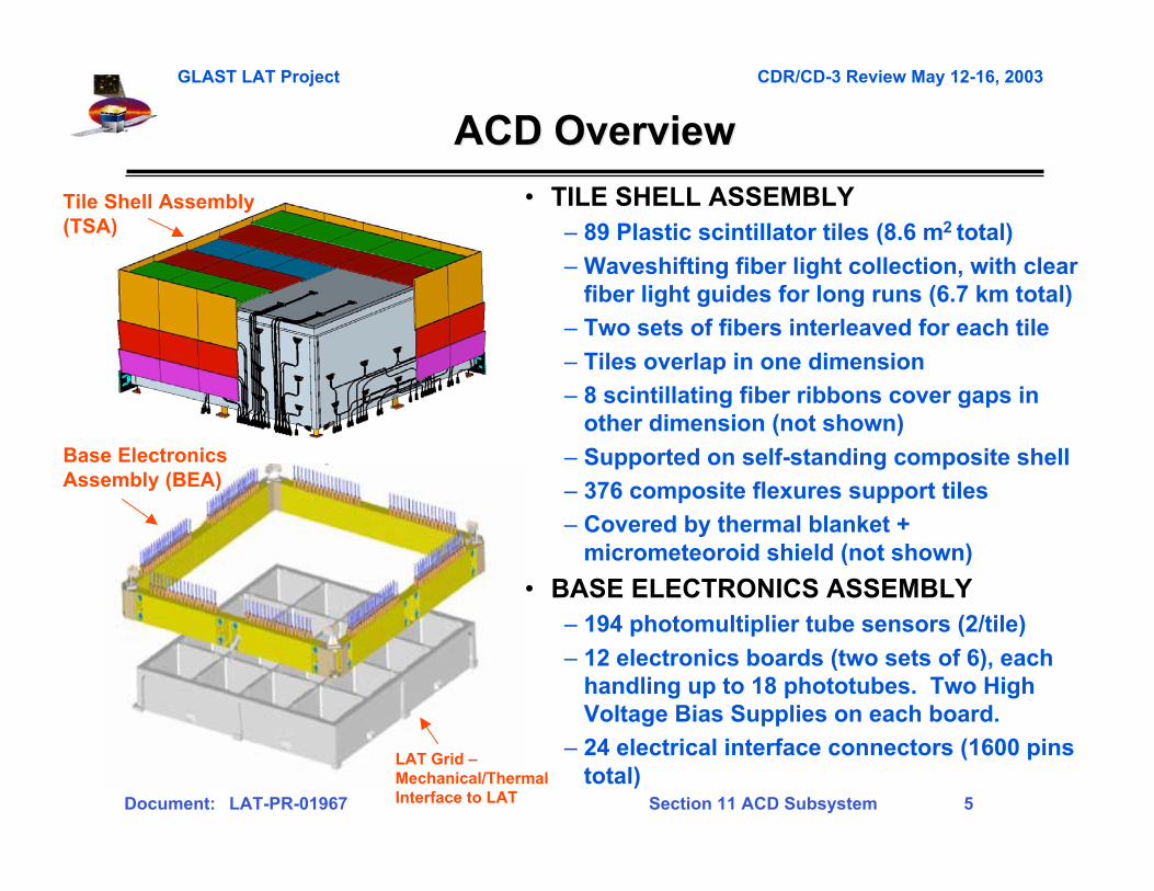
ACD OverviewACD Overview
• TILE SHELL ASSEMBLY– 89 Plastic scintillator tiles (8.6 m2 total)
– Waveshifting fiber light collection, with clearfiber light guides for long runs (6.7 km total)
– Two sets of fibers interleaved for each tile
– Tiles overlap in one dimension
– 8 scintillating fiber ribbons cover gaps inother dimension (not shown)
– Supported on self-standing composite shell
– 376 composite flexures support tiles
– Covered by thermal blanket +micrometeoroid shield (not shown)
• BASE ELECTRONICS ASSEMBLY– 194 photomultiplier tube sensors (2/tile)
– 12 electronics boards (two sets of 6), eachhandling up to 18 phototubes. Two HighVoltage Bias Supplies on each board.
– 24 electrical interface connectors (1600 pinstotal)
Base ElectronicsAssembly (BEA)
Tile Shell Assembly(TSA)
LAT Grid –Mechanical/ThermalInterface to LAT
GLAST LAT Project CDR/CD-3 Review May 12-16, 2003
Document: LAT-PR-01967 Section 11 ACD Subsystem 6
ACD Changes Since PDRACD Changes Since PDR
• Light Collection– Fibers were re-routed to shorter paths to minimize losses.– Use of fiber connectors and clear fibers was optimized.– The top center row of tiles was thickened to give more light.– Tile overlaps were increased to allow for vertical gaps required by
acoustic loads.– A triple layer (had been two) of square 1.5 mm fibers with offset centers
was adopted for the ribbons, to increase efficiency.• Mechanical
– Mechanical design was optimized to meet all environmental requirements,including new orbital debris model.
– A trade study for improving the light-tightness of the phototube housingwas conducted, and a new design was developed.
• Electrical– In order to improve reliability, a redundant High Voltage Bias Supply was
added to each electronics card.– The ASIC and electronics card designs are being finalized, correcting
some deficiencies from earlier versions.

GLAST LAT Project CDR/CD-3 Review May 12-16, 2003
Document: LAT-PR-01967 Section 11 ACD Subsystem 7
ACD Technical HeritageACD Technical Heritage
• Plastic Scintillator - used in all previous gamma-ray telescopes OSO-3,SAS-2, COS-B, CGRO (all 4 instruments), plus many cosmic rayexperiments.
• Waveshifting fibers - used in GLAST LAT Balloon Flight EngineeringModel (BFEM). Waveshifting bars used by HEXTE on RXTE (samematerial in a different geometry)
• Photomultiplier tubes - used in all previous gamma-ray telescopes.HEXTE/RXTE used a commercial version of the same tube we areusing (Hamamatsu 4443), and GOLF on SOHO used the same tube asthe ACD except for the cathode material (Hamamatsu 4444)
• High Voltage Bias Supplies - used in all previous gamma-raytelescopes, plus many cosmic ray experiments.
• Electronics - experienced ASIC designers. Discriminators, PHA andlogic signals similar to many flight instruments.
• Micrometeoroid Shield - Improved version (more layers, strongermaterials) of shield that protected EGRET successfully for nine years.
GLAST LAT Project CDR/CD-3 Review May 12-16, 2003
Document: LAT-PR-01967 Section 11 ACD Subsystem 8
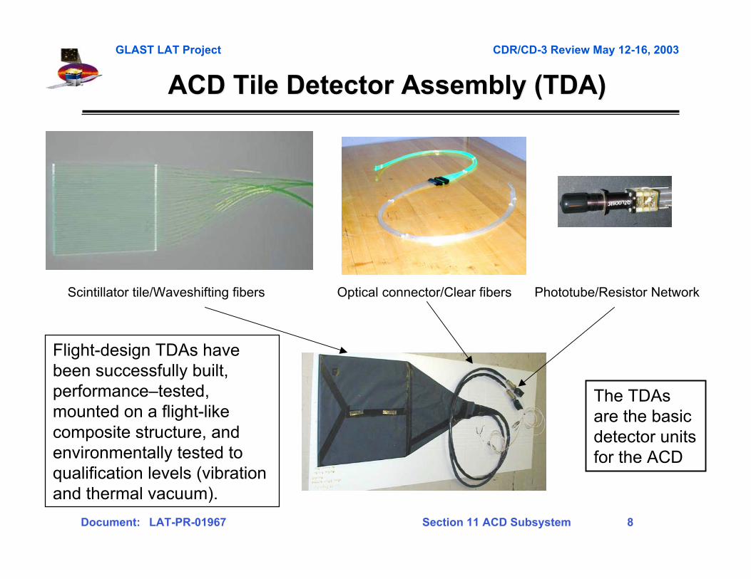
ACD Tile Detector Assembly (TDA)ACD Tile Detector Assembly (TDA)
Scintillator tile/Waveshifting fibers Optical connector/Clear fibers Phototube/Resistor Network
Flight-design TDAs havebeen successfully built,performance–tested,mounted on a flight-likecomposite structure, andenvironmentally tested toqualification levels (vibrationand thermal vacuum).
The TDAsare the basicdetector unitsfor the ACD

GLAST LAT Project CDR/CD-3 Review May 12-16, 2003
Document: LAT-PR-01967 Section 11 ACD Subsystem 9
Tile DetectorAssemblies 11/03
Shell 07/03Subassembly
ASIC 10/03Development
High Voltage BiasSupply 01/04
Photomultipliertubes 11/03
Front EndElectronicsCardAssembly01/04
Base Frame 09/03Subassembly
BaseElectronicsAssembly02/04
ACDIntegration03/04
Tile ShellAssembly12/03
ACDPerformanceandEnvironmentalTest 07/04
Thermal BlanketMicrometeoroidShield 03/04
Completion Dates Shown
ACD Work Flow Overview
Ship08/04
Tile Shell Assembly(TSA)
Base ElectronicsAssembly (BEA)
ElectronicsChassis01/04
GLAST LAT Project CDR/CD-3 Review May 12-16, 2003
Document: LAT-PR-01967 Section 11 ACD Subsystem 10
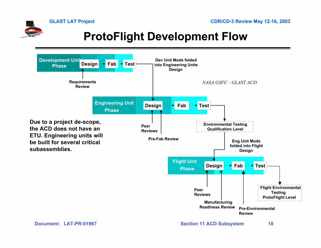
ProtoFlightProtoFlight Development Flow Development Flow
Due to a project de-scope,the ACD does not have anETU. Engineering units willbe built for several criticalsubassemblies.
Development UnitPhase Design Fab Test
Design Fab Test
PhaseDesign Fab Test
Flight Environmental Testing
ProtoFlight Level
Environmental TestingQualification Level
PeerReviews
PeerReviews
Dev Unit Mods foldedinto Engineering Units
Design
RequirementsReview
Eng Unit Modsfolded into Flight
Design
Pre-Fab Review
ManufacturingReadiness Review
NASA GSFC - GLAST ACD
Engineering Unit
Phase
Flight Unit
Pre-EnvironmentalReview
GLAST LAT Project CDR/CD-3 Review May 12-16, 2003
Document: LAT-PR-01967 Section 11 ACD Subsystem 11
ACD CDR RFA ResponsesACD CDR RFA Responses
• Of the 19 Requests for Action (RFA), only twoinvolved the actual design of the ACD(micrometeoroid shield, details of mounting the longbottom tile).
• Other RFAs involved testing, risk, spares plan,contamination, product assurance, GSE, andschedule.
• 17 of the 19 are now closed (and we expect the othertwo to be complete soon).
• Sample responses are shown on the next chart.
GLAST LAT Project CDR/CD-3 Review May 12-16, 2003
Document: LAT-PR-01967 Section 11 ACD Subsystem 12
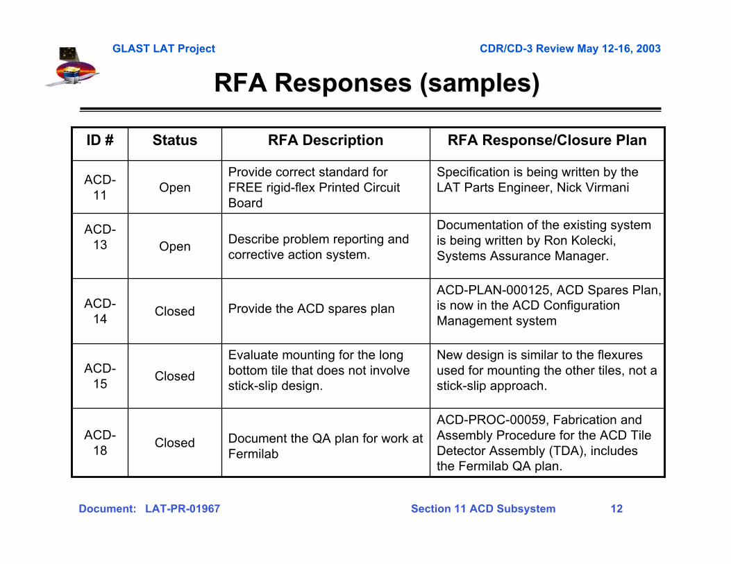
RFA Responses (samples)RFA Responses (samples)
New design is similar to the flexuresused for mounting the other tiles, not astick-slip approach.
Evaluate mounting for the longbottom tile that does not involvestick-slip design.
ClosedACD-
15
ACD-PLAN-000125, ACD Spares Plan,is now in the ACD ConfigurationManagement system
Provide the ACD spares planClosedACD-
14
Documentation of the existing systemis being written by Ron Kolecki,Systems Assurance Manager.
Describe problem reporting andcorrective action system.
OpenACD-
13
ACD-PROC-00059, Fabrication andAssembly Procedure for the ACD TileDetector Assembly (TDA), includesthe Fermilab QA plan.
Specification is being written by theLAT Parts Engineer, Nick Virmani
RFA Response/Closure Plan
Document the QA plan for work atFermilab
ClosedACD-
18
Provide correct standard forFREE rigid-flex Printed CircuitBoard
OpenACD-
11
RFA DescriptionStatusID #
GLAST LAT Project CDR/CD-3 Review May 12-16, 2003
Document: LAT-PR-01967 Section 11 ACD Subsystem 13
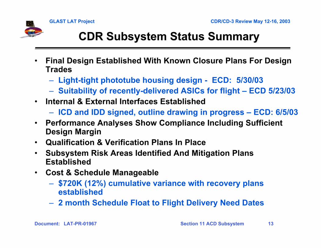
CDR Subsystem Status SummaryCDR Subsystem Status Summary
• Final Design Established With Known Closure Plans For DesignTrades– Light-tight phototube housing design - ECD: 5/30/03– Suitability of recently-delivered ASICs for flight – ECD 5/23/03
• Internal & External Interfaces Established– ICD and IDD signed, outline drawing in progress – ECD: 6/5/03
• Performance Analyses Show Compliance Including SufficientDesign Margin
• Qualification & Verification Plans In Place• Subsystem Risk Areas Identified And Mitigation Plans
Established• Cost & Schedule Manageable
– $720K (12%) cumulative variance with recovery plansestablished
– 2 month Schedule Float to Flight Delivery Need Dates

GLAST LAT Project CDR/CD-3 Review May 12-16, 2003
Document: LAT-PR-01967 Section 11 ACD Subsystem 14
Gamma-ray LargeGamma-ray LargeArea SpaceArea SpaceTelescopeTelescope
RequirementsRequirements
Section 11-2Section 11-2

GLAST LAT Project CDR/CD-3 Review May 12-16, 2003
Document: LAT-PR-01967 Section 11 ACD Subsystem 15
Level III Key Requirements SummaryLevel III Key Requirements Summary
Parameter Requirement Expected Performance Verification Method
Detection of Charged Particles
? 0.9997 average detection efficiency over entire area of ACD (0.99 for bottom row of tiles)
?0.9997
?0.999 (bottom tiles)
Test and Analysis
Fast VETO signal Logic signal 200-1600 nsec after passage of charged particle
200-1600 nsec Demonstrate
PHA signal For each phototube, pulse height measurement for each Trigger Acknowledge (TACK)
Below 10 MIP, precision of <0.02 MIP or 5% (whichever larger)
Above 10 MIP, precision of < 1 MIP or 2% (whichever larger)
< 0.02 MIP or 5%
< 1 MIP or 2%
Test and Analysis
False VETO rate - backsplash
< 20% false VETO's due to calorimeter backsplash at 300 GeV
< 10% Test and Analysis
False VETO rate - noise < 1% gamma-ray rejection from false VETO's due to electrical noise
< 1% Analysis
High Threshold (Heavy Nuclei) Detection
Detection of highly-ionized particles (C -N-O or heavier) for calorimeter calibration.
Yes Analysis
Size Outside: 1796 x1796 x 10 50 mm
1806 x 1806 for lowest 310mm
Inside Grid: 1574 x 1574 x 204.7 mm
Inside TKR: 1515.5 x 1515.5 x 650 mm
1796 x1796 x 1045 mm
1800 x 1800 at connector
1574 x 1574 x 204.7 mm
1515.5 x 1515.5 x 650mm
Demonstrate
Mass < 280 kg 270 kg Demonstrate
Power < 10.5 Watts (conditioned) 9.5 W Demonstrate
Instrument Lifetime Minimum 5 yrs > 5 yr. Analysis
Reference: LAT-SS-00016
GLAST LAT Project CDR/CD-3 Review May 12-16, 2003
Document: LAT-PR-01967 Section 11 ACD Subsystem 16
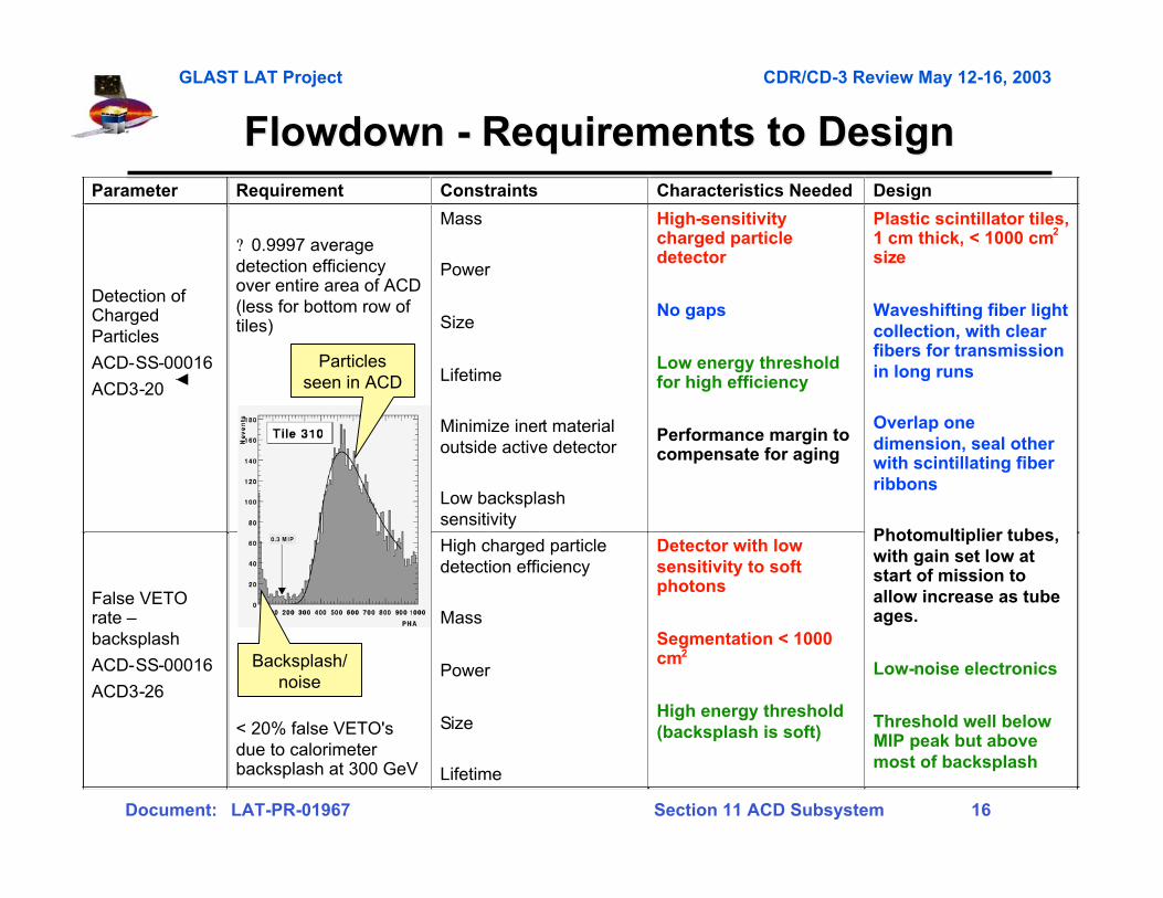
FlowdownFlowdown - Requirements to Design - Requirements to DesignParameter Requirement Constraints Characteristics Needed Design
Detection of Charged Particles
ACD-SS-00016
ACD3-20
? 0.9997 average detection efficiency over entire area of ACD (less for bottom row of tiles)
Mass
Power
Size
Lifetime
Minimize inert material outside active detector
Low backsplash sensitivity
High-sensitivity charged particle detector
No gaps
Low energy threshold for high efficiency
Performance margin to compensate for aging
False VETO rate – backsplash
ACD-SS-00016
ACD3-26
< 20% false VETO's due to calorimeter backsplash at 300 GeV
High charged particle detection efficiency
Mass
Power
Size
Lifetime
Detector with low sensitivity to soft photons
Segmentation < 1000 cm2
High energy threshold (backsplash is soft)
Plastic scintillator tiles, 1 cm thick, < 1000 cm2 size
Waveshifting fiber light collection, with clear fibers for transmission in long runs
Overlap one dimension, seal other with scintillating fiber ribbons
Photomultiplier tubes, with gain set low at start of mission to allow increase as tube ages.
Low-noise electronics
Threshold well below MIP peak but above most of backsplash
Particlesseen in ACD
Backsplash/noise

GLAST LAT Project CDR/CD-3 Review May 12-16, 2003
Document: LAT-PR-01967 Section 11 ACD Subsystem 17
Gamma-ray LargeGamma-ray LargeArea SpaceArea SpaceTelescopeTelescope
DesignDesign
Section 11-3Section 11-3
GLAST LAT Project CDR/CD-3 Review May 12-16, 2003
Document: LAT-PR-01967 Section 11 ACD Subsystem 18
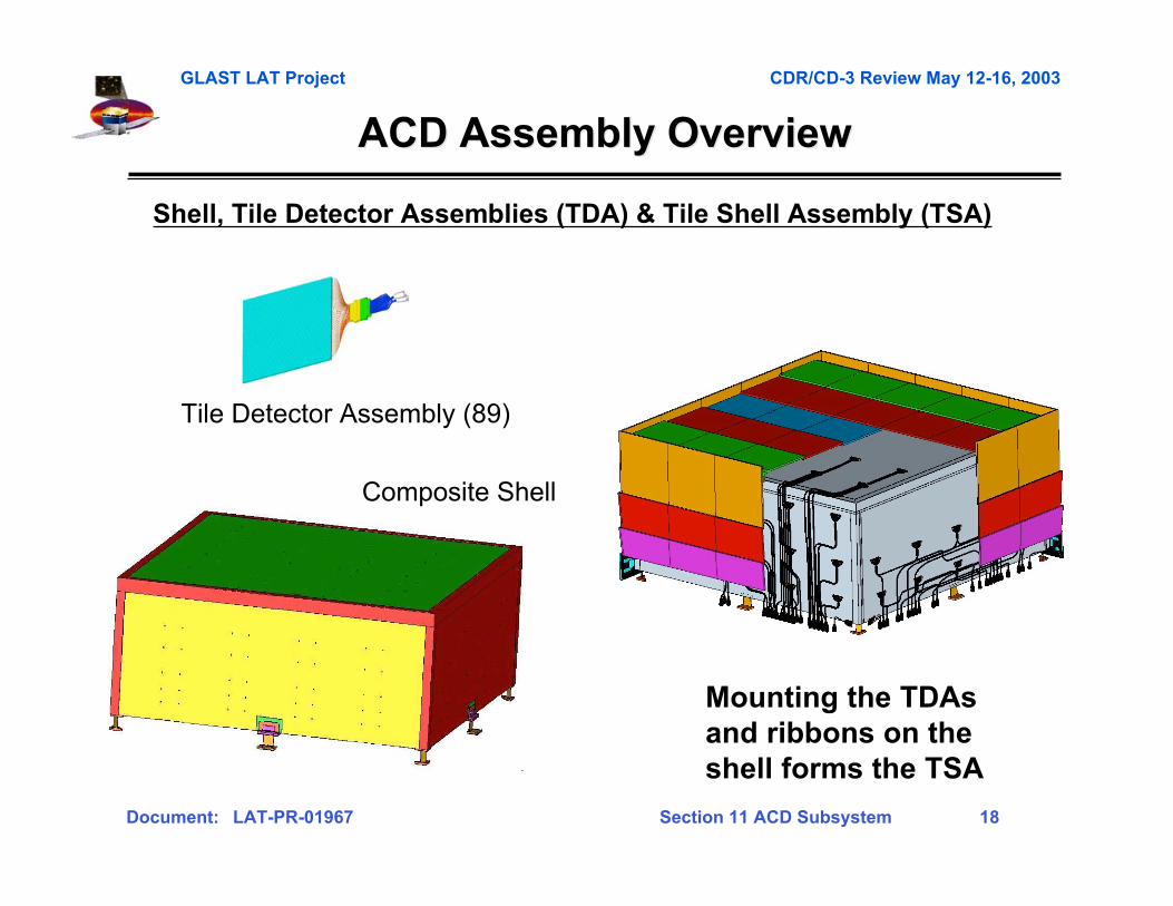
Shell, Tile Detector Assemblies (TDA) & Tile Shell Assembly (TSA)
Mounting the TDAsand ribbons on theshell forms the TSA
Composite Shell
ACD Assembly OverviewACD Assembly Overview
Tile Detector Assembly (89)

GLAST LAT Project CDR/CD-3 Review May 12-16, 2003
Document: LAT-PR-01967 Section 11 ACD Subsystem 19
ACD Assembly OverviewACD Assembly Overview
Base Frame Assembly
Electronics Chassis (12)– Phototubes, FREECards, HVBS
LAT Grid –Mechanical/ThermalInterface to LAT
Electronics Chassis, Base Frame, and Base Electronics Assembly (BEA)
Mounting the Electronics Chassis intothe Base Frame Assembly forms the BEA
GLAST LAT Project CDR/CD-3 Review May 12-16, 2003
Document: LAT-PR-01967 Section 11 ACD Subsystem 20
ACD Assembly OverviewACD Assembly Overview
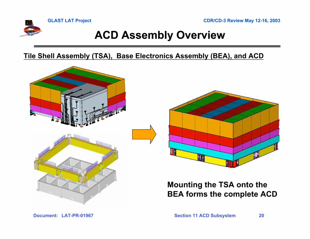
Tile Shell Assembly (TSA), Base Electronics Assembly (BEA), and ACD
Mounting the TSA onto theBEA forms the complete ACD
GLAST LAT Project CDR/CD-3 Review May 12-16, 2003
Document: LAT-PR-01967 Section 11 ACD Subsystem 21
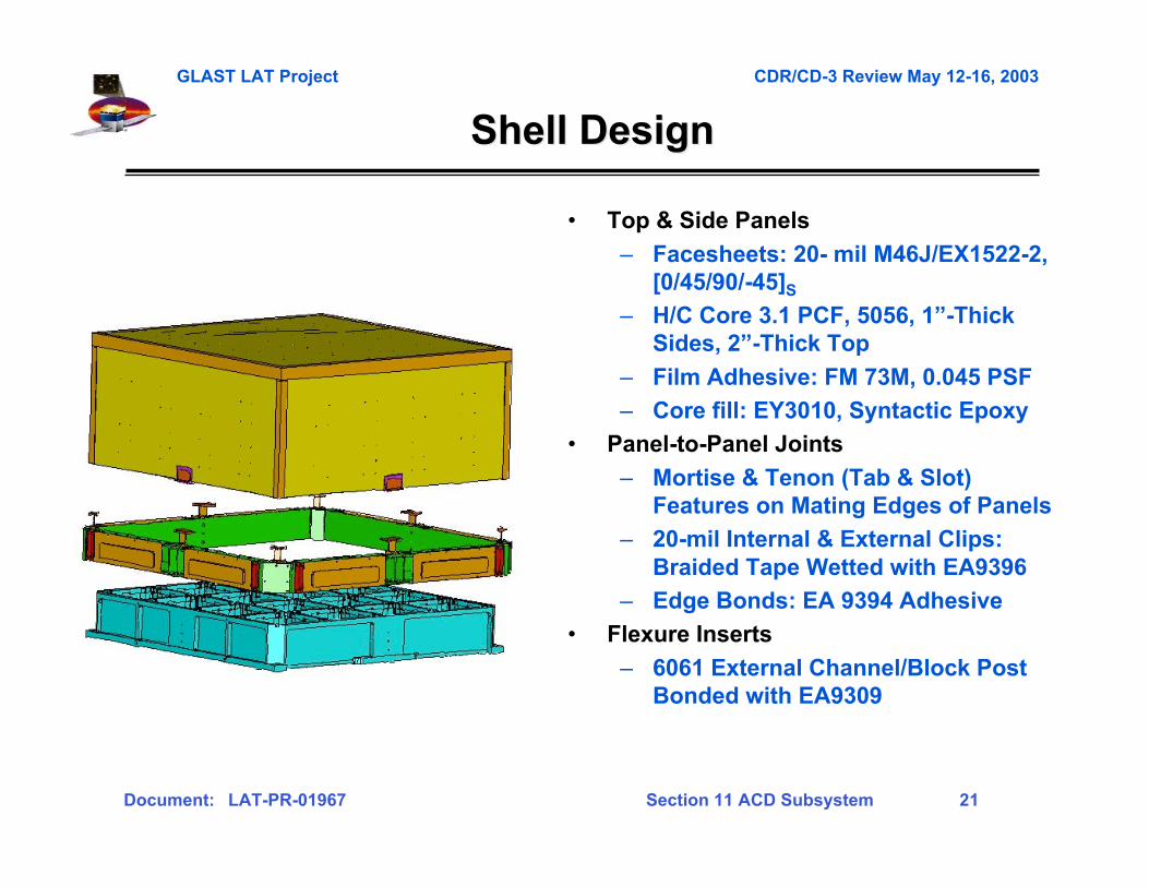
• Top & Side Panels
– Facesheets: 20- mil M46J/EX1522-2,[0/45/90/-45]S
– H/C Core 3.1 PCF, 5056, 1”-ThickSides, 2”-Thick Top
– Film Adhesive: FM 73M, 0.045 PSF
– Core fill: EY3010, Syntactic Epoxy
• Panel-to-Panel Joints
– Mortise & Tenon (Tab & Slot)Features on Mating Edges of Panels
– 20-mil Internal & External Clips:Braided Tape Wetted with EA9396
– Edge Bonds: EA 9394 Adhesive
• Flexure Inserts
– 6061 External Channel/Block PostBonded with EA9309
Shell DesignShell Design
GLAST LAT Project CDR/CD-3 Review May 12-16, 2003
Document: LAT-PR-01967 Section 11 ACD Subsystem 22
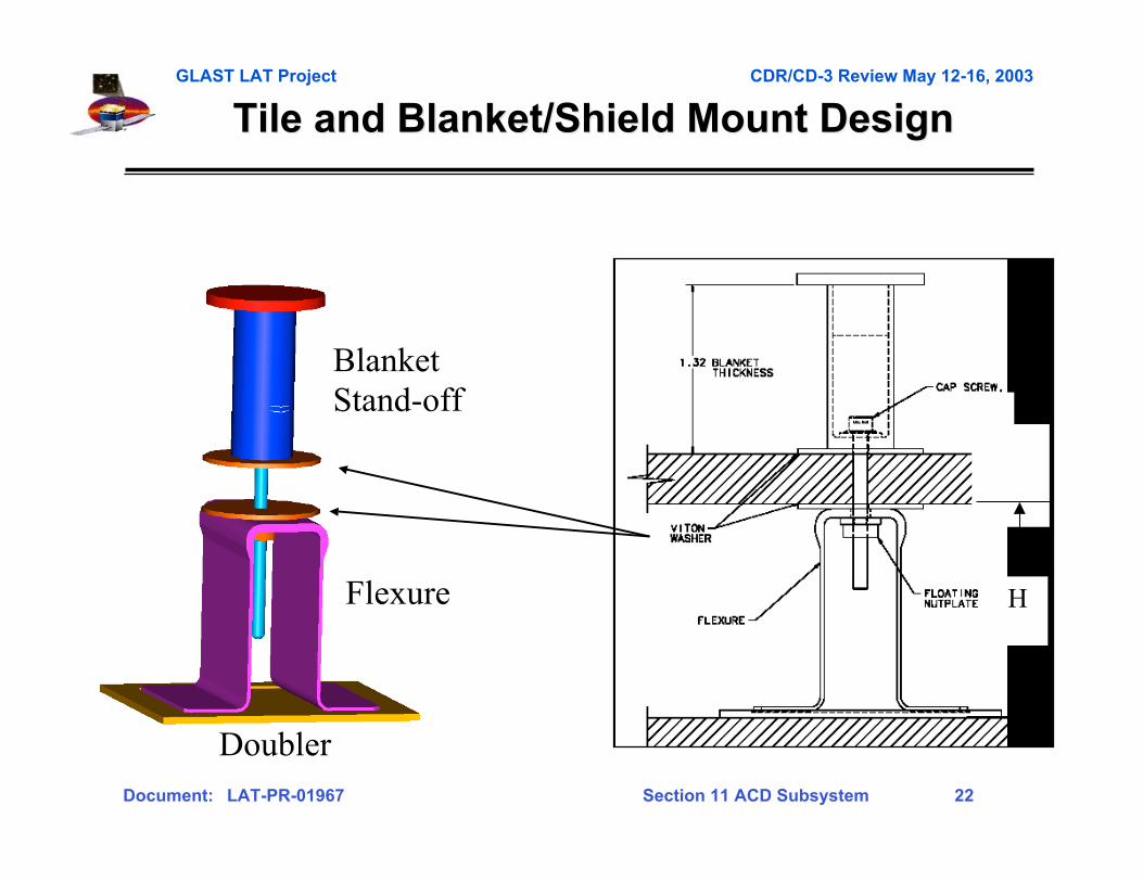
Tile and Blanket/Shield Mount DesignTile and Blanket/Shield Mount Design
Blanket Stand-off
Flexure
Doubler
H
GLAST LAT Project CDR/CD-3 Review May 12-16, 2003
Document: LAT-PR-01967 Section 11 ACD Subsystem 23
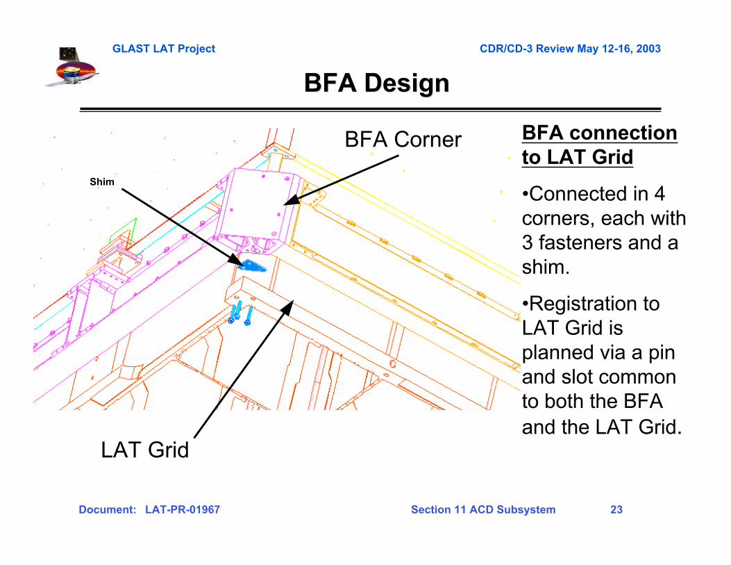
BFA DesignBFA Design
BFA connectionto LAT Grid
•Connected in 4corners, each with3 fasteners and ashim.
•Registration toLAT Grid isplanned via a pinand slot commonto both the BFAand the LAT Grid.
BFA Corner
LAT Grid
Shim
GLAST LAT Project CDR/CD-3 Review May 12-16, 2003
Document: LAT-PR-01967 Section 11 ACD Subsystem 24
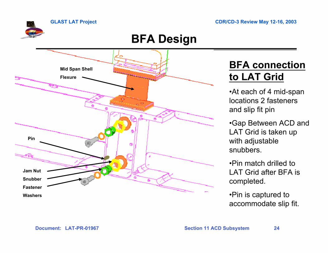
BFA DesignBFA Design
BFA connectionto LAT Grid
•At each of 4 mid-spanlocations 2 fastenersand slip fit pin
•Gap Between ACD andLAT Grid is taken upwith adjustablesnubbers.
•Pin match drilled toLAT Grid after BFA iscompleted.
•Pin is captured toaccommodate slip fit.
Jam Nut
Snubber
Fastener
Washers
Pin
Mid Span Shell
Flexure
GLAST LAT Project CDR/CD-3 Review May 12-16, 2003
Document: LAT-PR-01967 Section 11 ACD Subsystem 25
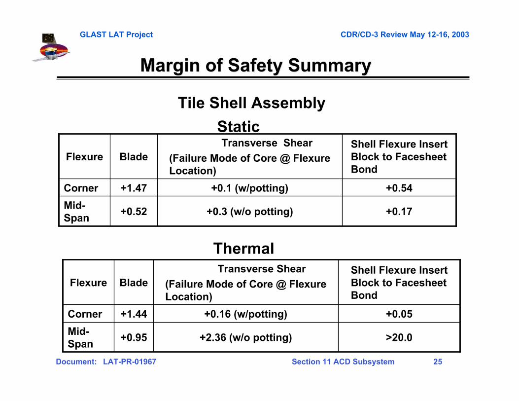
+0.17+0.3 (w/o potting)+0.52Mid-Span
+0.54+0.1 (w/potting)+1.47Corner
Shell Flexure InsertBlock to FacesheetBond
Transverse Shear
(Failure Mode of Core @ FlexureLocation)
BladeFlexure
>20.0+2.36 (w/o potting)+0.95Mid-Span
+0.05+0.16 (w/potting)+1.44Corner
Shell Flexure InsertBlock to FacesheetBond
Transverse Shear
(Failure Mode of Core @ FlexureLocation)
BladeFlexure
Margin of Safety SummaryMargin of Safety Summary
Static
Thermal
Tile Shell Assembly
GLAST LAT Project CDR/CD-3 Review May 12-16, 2003
Document: LAT-PR-01967 Section 11 ACD Subsystem 26
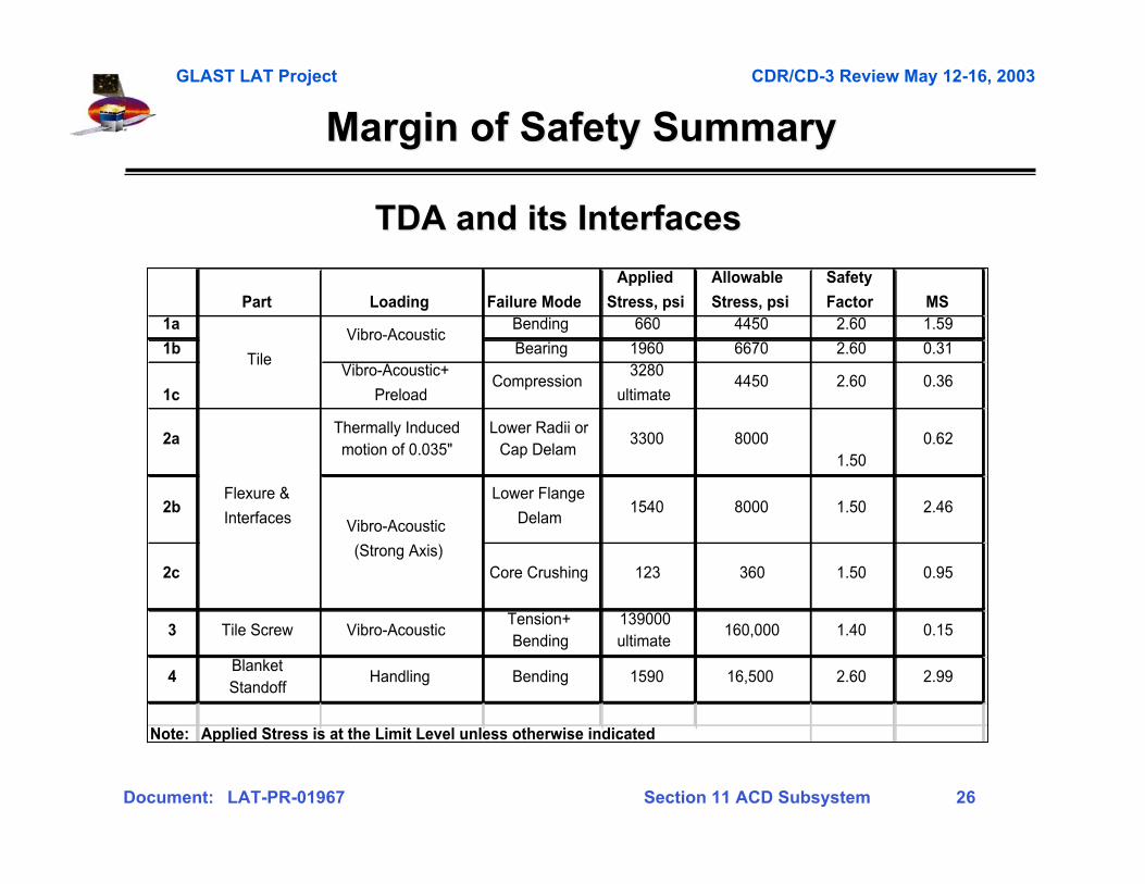
Margin of Safety SummaryMargin of Safety Summary
Part Loading Failure Mode
Applied
Stress, psi
Allowable
Stress, psi
Safety
Factor MS1a Bending 660 4450 2.60 1.59
1b Bearing 1960 6670 2.60 0.31
1c
Vibro-Acoustic+
PreloadCompression
3280
ultimate4450 2.60 0.36
2aThermally Induced motion of 0.035"
Lower Radii or Cap Delam
3300 80001.50
0.62
2bLower Flange
Delam1540 8000 1.50 2.46
2c Core Crushing 123 360 1.50 0.95
3 Tile Screw Vibro-AcousticTension+Bending
139000ultimate
160,000 1.40 0.15
4Blanket Standoff
Handling Bending 1590 16,500 2.60 2.99
Note: Applied Stress is at the Limit Level unless otherwise indicated
Vibro-Acoustic
(Strong Axis)
Flexure &
Interfaces
Vibro-Acoustic
Tile
TDA and its InterfacesTDA and its Interfaces
GLAST LAT Project CDR/CD-3 Review May 12-16, 2003
Document: LAT-PR-01967 Section 11 ACD Subsystem 27
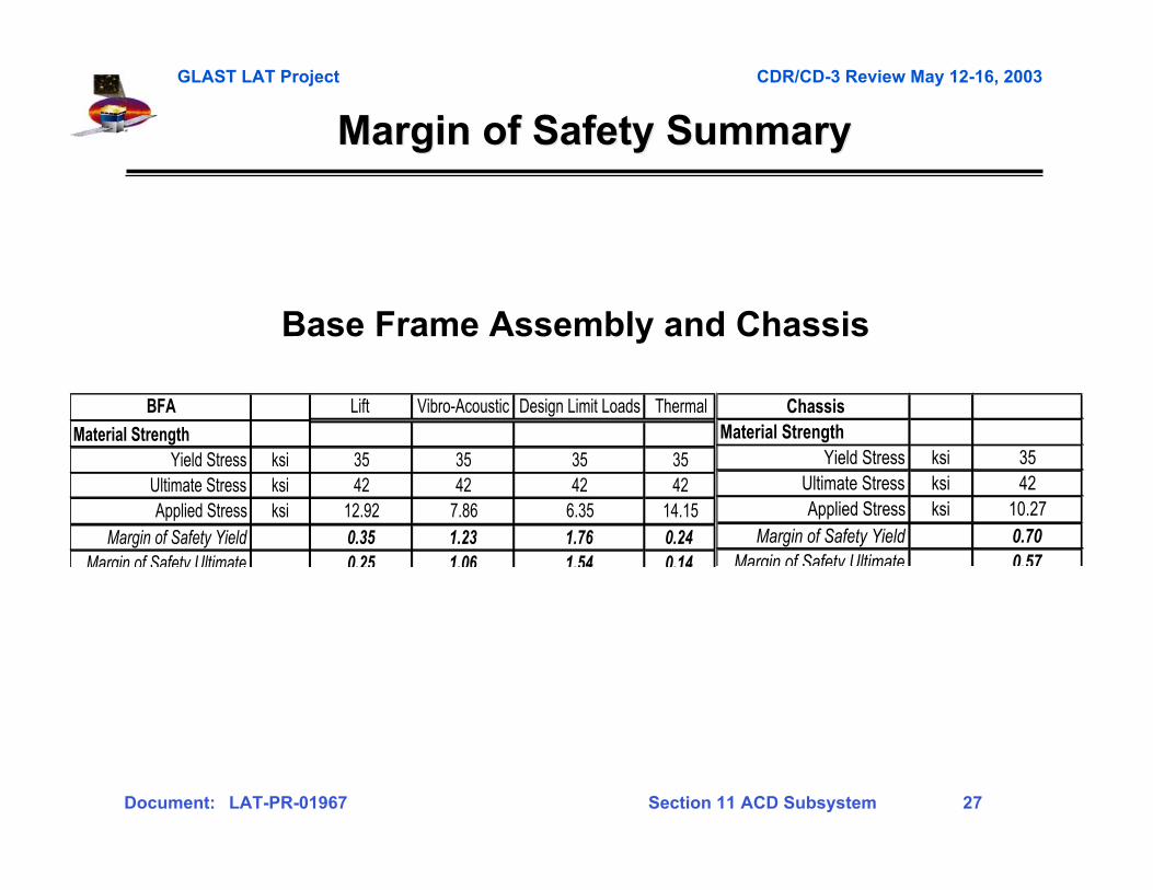
Margin of Safety SummaryMargin of Safety Summary
BFA Lift Vibro-Acoustic Design Limit Loads Thermal
Material StrengthYield Stress ksi 35 35 35 35
Ultimate Stress ksi 42 42 42 42Applied Stress ksi 12.92 7.86 6.35 14.15
Margin of Safety Yield 0.35 1.23 1.76 0.24Margin of Safety Ultimate 0.25 1.06 1.54 0.14
ChassisMaterial Strength
Yield Stress ksi 35Ultimate Stress ksi 42Applied Stress ksi 10.27
Margin of Safety Yield 0.70Margin of Safety Ultimate 0.57
Base Frame Assembly and Chassis
GLAST LAT Project CDR/CD-3 Review May 12-16, 2003
Document: LAT-PR-01967 Section 11 ACD Subsystem 28
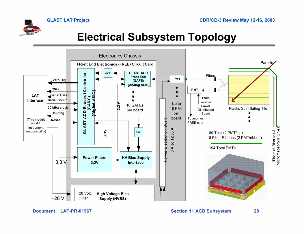
Electrical Subsystem TopologyElectrical Subsystem Topology
PMT
PMT
LATInterface
(This moduleis LAT
instrumentresponsibility)
Fibers
Particle
Plastic Scintillating Tile
Th
em
al
Bla
nke
t &
Mic
rom
ete
oro
id S
hie
ld
89 Tiles (2 PMT/tile)8 Fiber Ribbons (2 PMT/ribbon)
194 Total PMTs
FromanotherPower
DistributionBoard
GLAST ACDFront End
(GAFE)[Analog ASIC]
GL
AS
T A
CD
Re
ad
ou
t C
on
tro
lle
r(G
AR
C)
[Dig
ita
l A
SIC
]
Power Filters3.3V
HV Bias SupplyInterface
High Voltage BiasSupply (HVBS)
FRont End Electronics (FREE) Circuit Card
Veto (18)
Serial Data
Serial Comm.
0 V
to
12
50
V
3.3
V
3.3
V18 GAFEsper board
Hskping
ADC
DAC
Po
we
r D
istr
ibu
tio
n B
oa
rd To anotherFREE card
CNO
20 MHz clock
Reset
+28 VoltFilter
+3.3 V
+28 V
Up to18 PMT
perboard
Electronics Chassis
GLAST LAT Project CDR/CD-3 Review May 12-16, 2003
Document: LAT-PR-01967 Section 11 ACD Subsystem 29
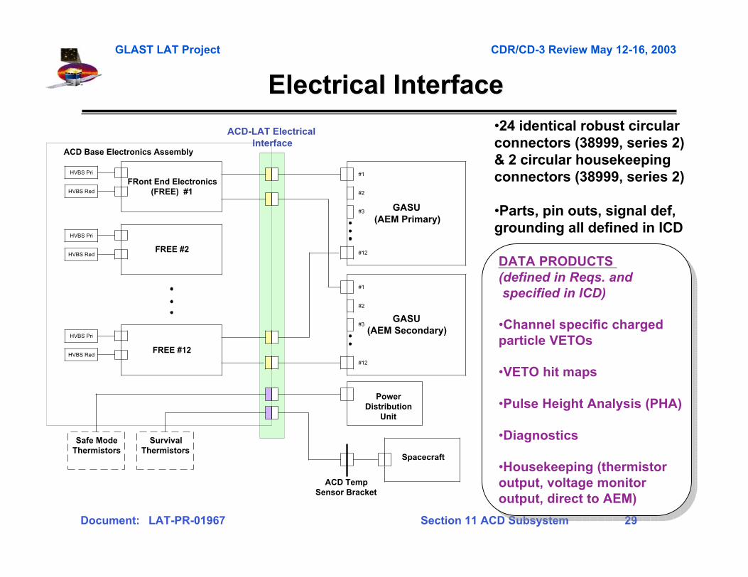
Electrical InterfaceElectrical Interface•24 identical robust circularconnectors (38999, series 2)& 2 circular housekeepingconnectors (38999, series 2)
•Parts, pin outs, signal def,grounding all defined in ICD
DATA PRODUCTS (defined in Reqs. and specified in ICD)
•Channel specific charged particle VETOs
•VETO hit maps
•Pulse Height Analysis (PHA)
•Diagnostics
•Housekeeping (thermistor output, voltage monitor output, direct to AEM)
DATA PRODUCTS (defined in Reqs. and specified in ICD)
•Channel specific charged particle VETOs
•VETO hit maps
•Pulse Height Analysis (PHA)
•Diagnostics
•Housekeeping (thermistor output, voltage monitor output, direct to AEM)
FRont End Electronics(FREE) #1
HVBS Pri
HVBS Red
FREE #2
HVBS Pri
HVBS Red
FREE #12
HVBS Pri
HVBS Red
GASU(AEM Primary)
#1
#2
#3
#12
GASU(AEM Secondary)
#1
#2
#3
#12
Safe ModeThermistors
SurvivalThermistors
ACD Base Electronics Assembly
PowerDistribution
Unit
Spacecraft
ACD-LAT ElectricalInterface
ACD TempSensor Bracket
GLAST LAT Project CDR/CD-3 Review May 12-16, 2003
Document: LAT-PR-01967 Section 11 ACD Subsystem 30
Electronics Component Design VerificationElectronics Component Design Verification
• ASICs to be tested & screened with a separate bench-top teststation at GSFC
• Maxim 145 and Maxim 5121 will be screened at NRL anddelivered to GSFC
• Maxim 494 to be screened by GSFC
• Front-end Electronics boards to be performance andenvironmental tested at GSFC prior to integration with ACD
• High Voltage Bias Supplies to be performance andenvironmental tested at GSFC prior to integration with ACD
• Photomultiplier Tubes will be screened by a flight-approvedvendor and tested at GSFC prior to integration with ACD
• Biasing Resistor Networks will be performance andenvironmental tested at GSFC prior to integration to ACD
– Level IV Requirement 5.12Radiation Tolerance. TheACD electronics shallremain within specificationsafter a total ionizingradiation dose of 4.5kRad(Si).
– Level IV Requirement5.12.1 Single Event UpsetTolerance. A single eventupset (SEU) shall notcause the ACD electronicsto transition to an unsafestate.
– Level IV Requirement5.12.2 Latchup Tolerance.Parts that show any SEE’sat an LET lower than 37MeV*cm2/mg shall notdegrade the missionperformance.
GLAST LAT Project CDR/CD-3 Review May 12-16, 2003
Document: LAT-PR-01967 Section 11 ACD Subsystem 31
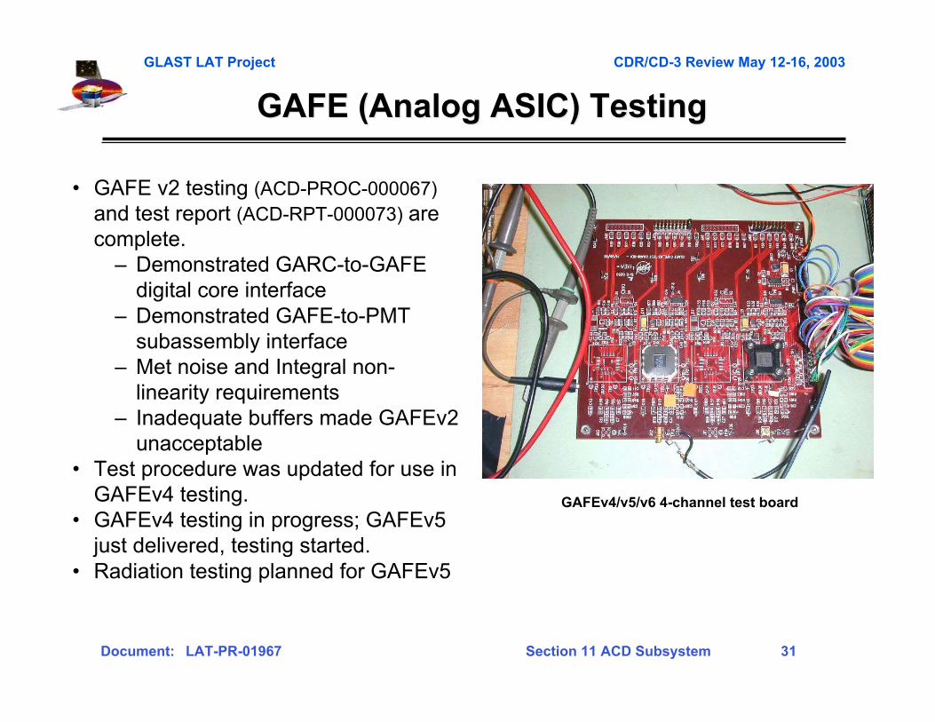
GAFE (Analog ASIC) TestingGAFE (Analog ASIC) Testing
• GAFE v2 testing (ACD-PROC-000067)and test report (ACD-RPT-000073) arecomplete.
– Demonstrated GARC-to-GAFEdigital core interface
– Demonstrated GAFE-to-PMTsubassembly interface
– Met noise and Integral non-linearity requirements
– Inadequate buffers made GAFEv2unacceptable
• Test procedure was updated for use inGAFEv4 testing.
• GAFEv4 testing in progress; GAFEv5just delivered, testing started.
• Radiation testing planned for GAFEv5
GAFEv4/v5/v6 4-channel test board

GLAST LAT Project CDR/CD-3 Review May 12-16, 2003
Document: LAT-PR-01967 Section 11 ACD Subsystem 32
GARC (Digital ASIC) TestingGARC (Digital ASIC) Testing
• GARCv1 fully tested. GARCv2 just delivered, testing started.• Test report details available (ACD-RPT-000073)
Identified 9 issues with GARCv1. All were straight-forward and simplefixes to a good design. GARCv2 has one known (not fatal) problem.
• GARC test procedure is developed and is being used to test GARCv2
GARC test board
Windows PC
AEM GSETest Board
COM Port
GARC TestBoard
(w/socket)
ACD GAFESimulator
orGAFE Test Board
+5VPowerSupply
+3.3VPowerSupply
+3.3VPowerSupply
GARC CurrentMeter
TextronixTDS754
Oscilloscope
GLAST LAT Project CDR/CD-3 Review May 12-16, 2003
Document: LAT-PR-01967 Section 11 ACD Subsystem 33
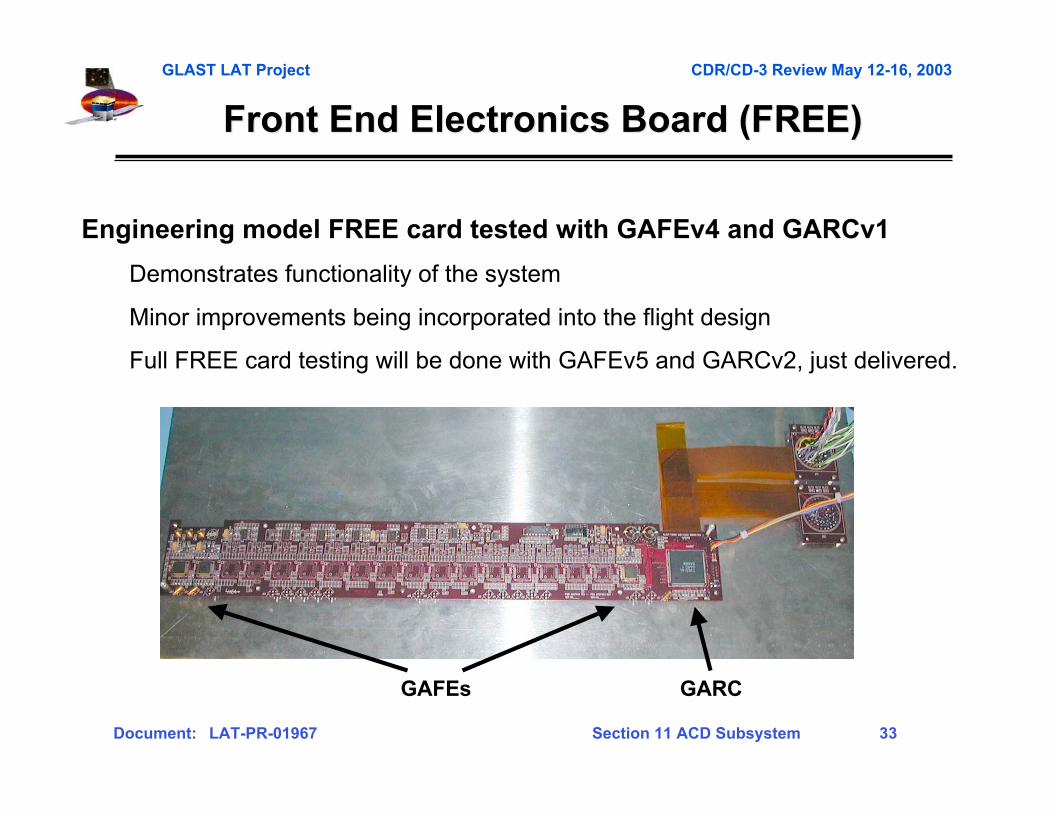
Front End Electronics Board (FREE)Front End Electronics Board (FREE)
GARCGAFEs
Engineering model FREE card tested with GAFEv4 and GARCv1
Demonstrates functionality of the system
Minor improvements being incorporated into the flight design
Full FREE card testing will be done with GAFEv5 and GARCv2, just delivered.
GLAST LAT Project CDR/CD-3 Review May 12-16, 2003
Document: LAT-PR-01967 Section 11 ACD Subsystem 34
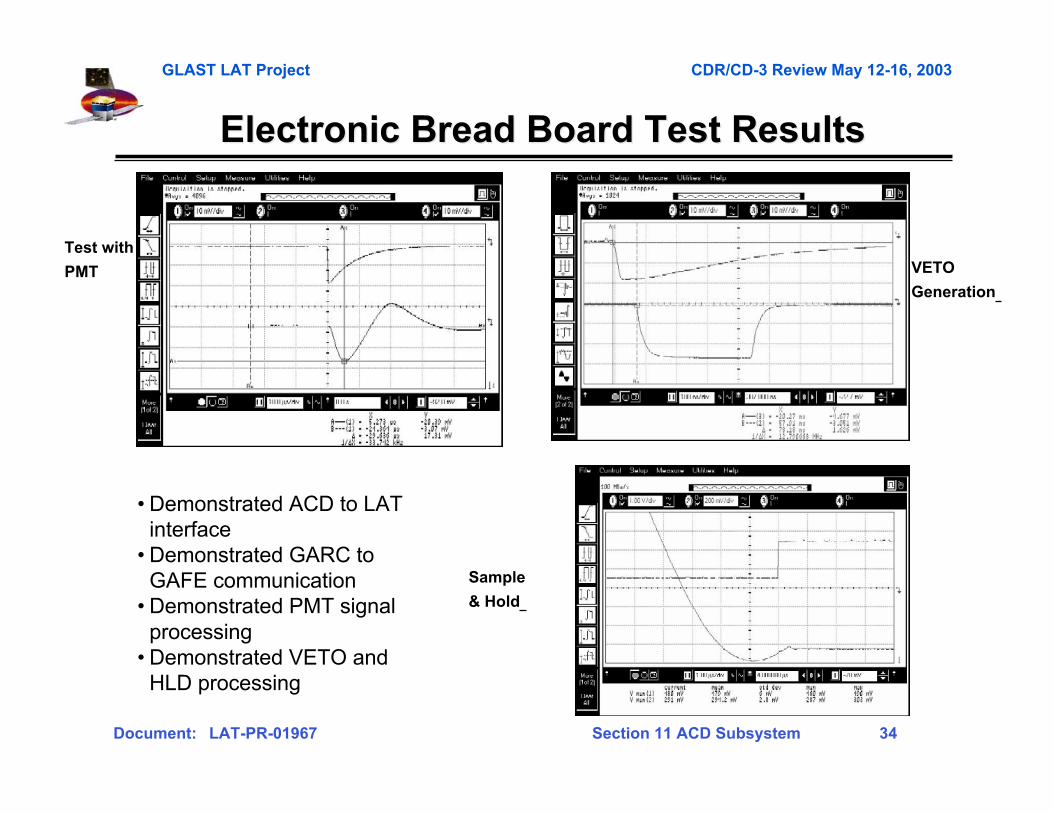
Electronic Bread Board Test ResultsElectronic Bread Board Test Results
Sample
& Hold
VETO
Generation
Test with
PMT
• Demonstrated ACD to LATinterface
• Demonstrated GARC toGAFE communication
• Demonstrated PMT signalprocessing
• Demonstrated VETO andHLD processing
GLAST LAT Project CDR/CD-3 Review May 12-16, 2003
Document: LAT-PR-01967 Section 11 ACD Subsystem 35
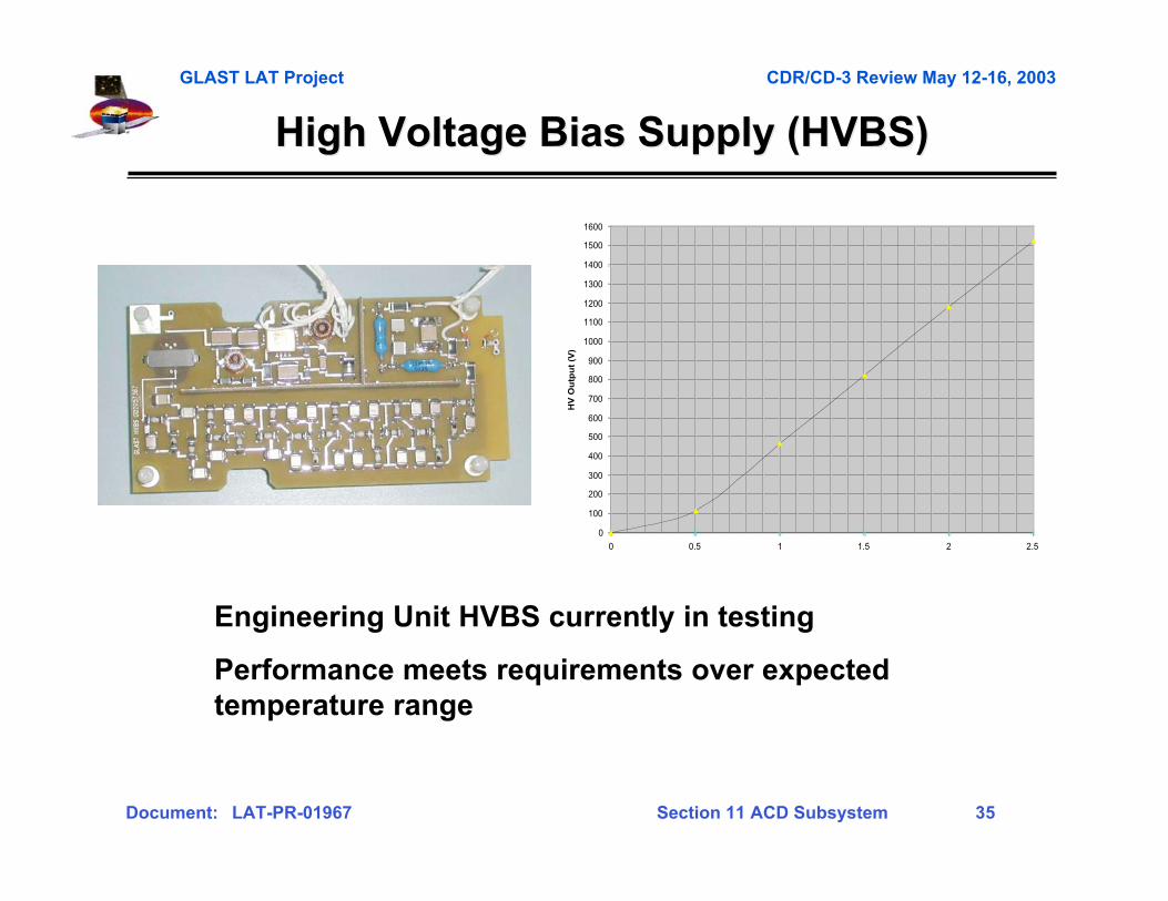
High Voltage Bias Supply (HVBS)High Voltage Bias Supply (HVBS)
0
100
200
300
400
500
600
700
800
900
1000
1100
1200
1300
1400
1500
1600
0 0.5 1 1.5 2 2.5
HV
Ou
tpu
t (V
)
Engineering Unit HVBS currently in testing
Performance meets requirements over expectedtemperature range
GLAST LAT Project CDR/CD-3 Review May 12-16, 2003
Document: LAT-PR-01967 Section 11 ACD Subsystem 36
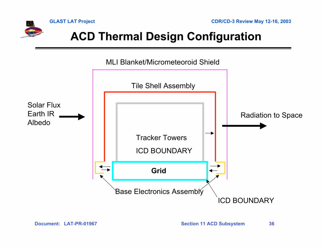
ACD Thermal Design ConfigurationACD Thermal Design Configuration
Tracker Towers
ICD BOUNDARY
Grid
Tile Shell Assembly
MLI Blanket/Micrometeoroid Shield
Base Electronics AssemblyICD BOUNDARY
Radiation to SpaceSolar FluxEarth IRAlbedo
GLAST LAT Project CDR/CD-3 Review May 12-16, 2003
Document: LAT-PR-01967 Section 11 ACD Subsystem 37
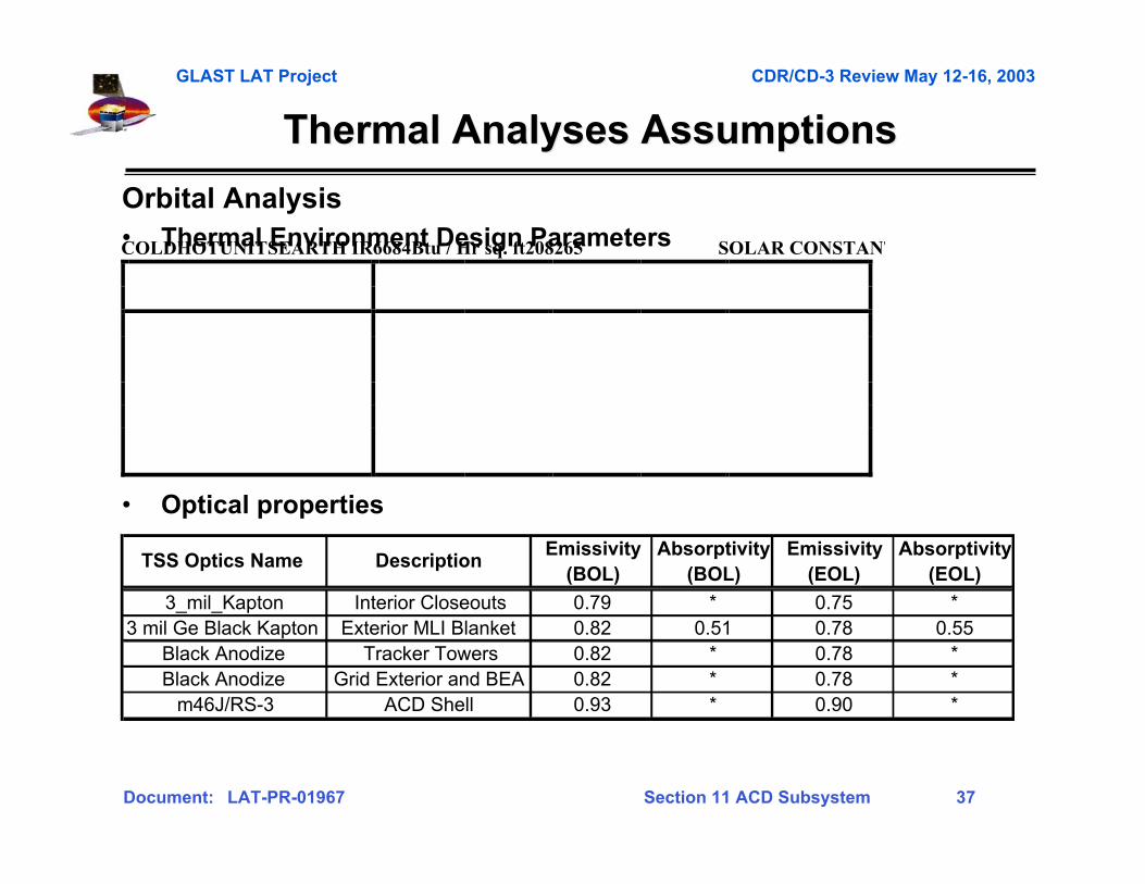
Thermal Analyses AssumptionsThermal Analyses Assumptions
Orbital Analysis• Thermal Environment Design Parameters
• Optical properties
COLDHOTUNITSEARTH IR6684Btu / Hr sq. ft208265 SOLAR CONSTANT
TSS Optics Name DescriptionEmissivity
(BOL)Absorptivity
(BOL)Emissivity
(EOL)Absorptivity
(EOL)
3_mil_Kapton Interior Closeouts 0.79 * 0.75 *3 mil Ge Black Kapton Exterior MLI Blanket 0.82 0.51 0.78 0.55
Black Anodize Tracker Towers 0.82 * 0.78 *Black Anodize Grid Exterior and BEA 0.82 * 0.78 *
m46J/RS-3 ACD Shell 0.93 * 0.90 *
GLAST LAT Project CDR/CD-3 Review May 12-16, 2003
Document: LAT-PR-01967 Section 11 ACD Subsystem 38
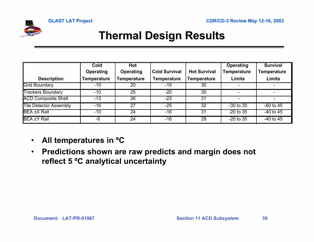
Thermal Design ResultsThermal Design Results
• All temperatures in ºC
• Predictions shown are raw predicts and margin does notreflect 5 ºC analytical uncertainty
Description
Cold Operating
Temperature
Hot Operating
Temperature
Cold Survival
Temperature
Hot Survival
Temperature
Operating Temperature
Limits
Survival Temperature
LimitsGrid Boundary -10 20 -15 30 - -
Trackers Boundary -10 25 -20 30 - -ACD Composite Shell -13 26 -23 31 - -
Tile Detector Assembly -16 27 -25 32 -30 to 35 -60 to 45BEA ±X Rail -10 24 -16 31 -20 to 35 -40 to 45
BEA ±Y Rail -9 24 -16 29 -20 to 35 -40 to 45
GLAST LAT Project CDR/CD-3 Review May 12-16, 2003
Document: LAT-PR-01967 Section 11 ACD Subsystem 39
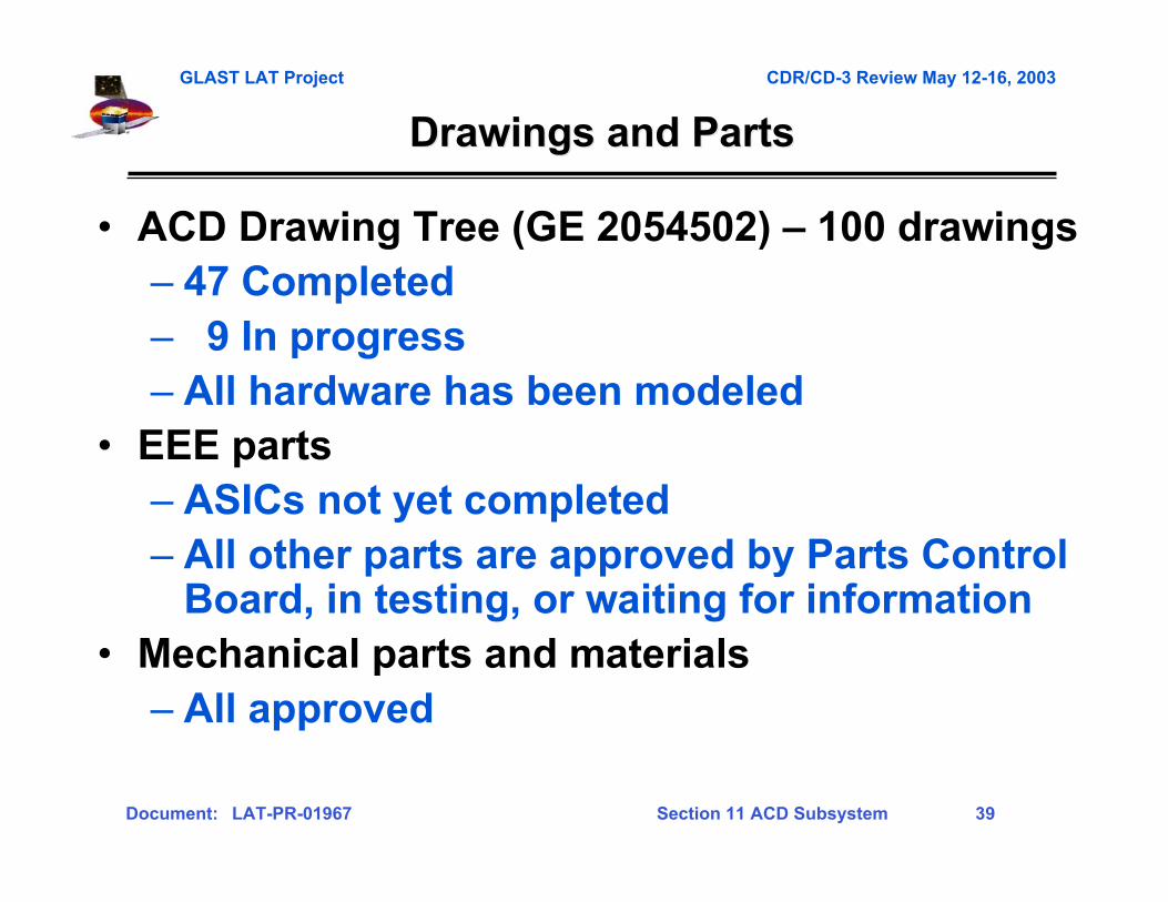
Drawings and PartsDrawings and Parts
• ACD Drawing Tree (GE 2054502) – 100 drawings– 47 Completed– 9 In progress– All hardware has been modeled
• EEE parts– ASICs not yet completed– All other parts are approved by Parts Control
Board, in testing, or waiting for information• Mechanical parts and materials– All approved

GLAST LAT Project CDR/CD-3 Review May 12-16, 2003
Document: LAT-PR-01967 Section 11 ACD Subsystem 40
Gamma-ray LargeGamma-ray LargeArea SpaceArea SpaceTelescopeTelescope
Verification ProgramVerification Program
Section 11-4Section 11-4
GLAST LAT Project CDR/CD-3 Review May 12-16, 2003
Document: LAT-PR-01967 Section 11 ACD Subsystem 41
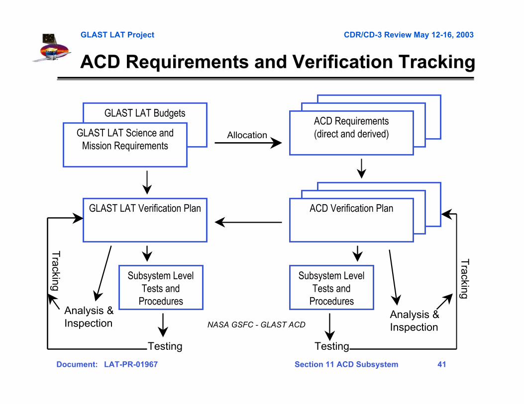
ACD Requirements and Verification TrackingACD Requirements and Verification Tracking
GLAST LAT Budgets
GLAST LAT Science andMission Requirements
ACD Requirements(direct and derived)
Subsystem LevelTests and
Procedures
GLAST LAT Verification Plan ACD Verification Plan
Subsystem LevelTests and
Procedures
Testing
Analysis & Inspection
Tracking
Testing
Analysis & Inspection
Tracking
Allocation
NASA GSFC - GLAST ACD
GLAST LAT Project CDR/CD-3 Review May 12-16, 2003
Document: LAT-PR-01967 Section 11 ACD Subsystem 42
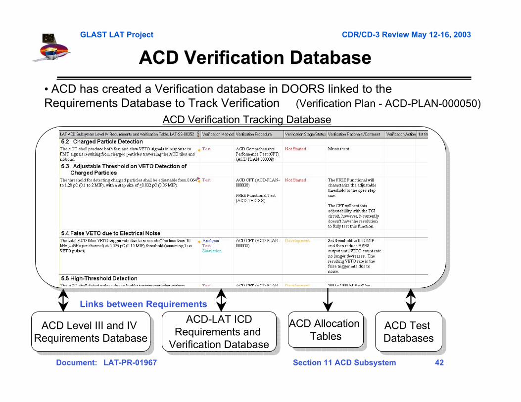
ACD Verification Database ACD Verification Database
ACD Verification Tracking Database
ACD-LAT ICDRequirements and
Verification Database
ACD-LAT ICDRequirements and
Verification Database
Links between Requirements
• ACD has created a Verification database in DOORS linked to the Requirements Database to Track Verification (Verification Plan - ACD-PLAN-000050)
ACD Level III and IV Requirements Database
ACD Level III and IV Requirements Database
ACD Test Databases
ACD Test Databases
ACD Allocation Tables
ACD Allocation Tables

GLAST LAT Project CDR/CD-3 Review May 12-16, 2003
Document: LAT-PR-01967 Section 11 ACD Subsystem 43
Performance Testing - Efficiency DemonstrationPerformance Testing - Efficiency Demonstration
This approach also determines margins and relative importance of thecontributors to the entire efficiency
measure the performancefor active elements (tiles,
fiber ribbons)
measure thecharacteristics ofpassive elements
(WLS and clear fibers)
measure valuesfor dead areas
(gaps)
put everything in thesimulation code to determine
the resulting efficiency
check the results by measuring the efficiencydirectly in several areas of ACD and comparing
with that obtained by simulations
The approach:
GLAST LAT Project CDR/CD-3 Review May 12-16, 2003
Document: LAT-PR-01967 Section 11 ACD Subsystem 44
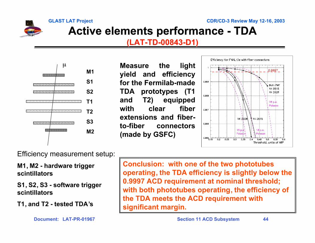
Active elements performance - TDAActive elements performance - TDA(LAT-TD-00843-D1)(LAT-TD-00843-D1)
Efficiency measurement setup:
M1, M2 - hardware triggerscintillators
S1, S2, S3 - software triggerscintillators
T1, and T2 - tested TDA’s
µM1
S1
S2
T1
T2
S3
M2
Measure the lightyield and efficiencyfor the Fermilab-madeTDA prototypes (T1and T2) equippedwith clear fiberextensions and fiber-to-fiber connectors(made by GSFC)
Conclusion: with one of the two phototubesoperating, the TDA efficiency is slightly below the0.9997 ACD requirement at nominal threshold;with both phototubes operating, the efficiency ofthe TDA meets the ACD requirement withsignificant margin.
GLAST LAT Project CDR/CD-3 Review May 12-16, 2003
Document: LAT-PR-01967 Section 11 ACD Subsystem 45
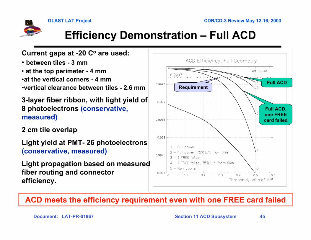
Efficiency Demonstration Efficiency Demonstration –– Full ACD Full ACD
Current gaps at -20 Co are used:• between tiles - 3 mm• at the top perimeter - 4 mm•at the vertical corners - 4 mm•vertical clearance between tiles - 2.6 mm
3-layer fiber ribbon, with light yield of8 photoelectrons (conservative,measured)
2 cm tile overlap
Light yield at PMT- 26 photoelectrons(conservative, measured)
Light propagation based on measuredfiber routing and connectorefficiency.
ACD meets the efficiency requirement even with one FREE card failed
Requirement
Full ACD,one FREEcard failed
Full ACD
GLAST LAT Project CDR/CD-3 Review May 12-16, 2003
Document: LAT-PR-01967 Section 11 ACD Subsystem 46
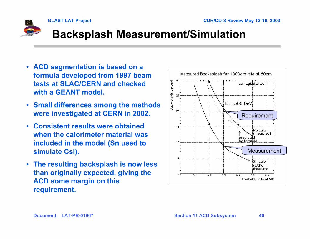
Backsplash Measurement/Simulation
Requirement
Measurement
• ACD segmentation is based on aformula developed from 1997 beamtests at SLAC/CERN and checkedwith a GEANT model.
• Small differences among the methodswere investigated at CERN in 2002.
• Consistent results were obtainedwhen the calorimeter material wasincluded in the model (Sn used tosimulate CsI).
• The resulting backsplash is now lessthan originally expected, giving theACD some margin on thisrequirement.
GLAST LAT Project CDR/CD-3 Review May 12-16, 2003
Document: LAT-PR-01967 Section 11 ACD Subsystem 47
ACD Testing OverviewACD Testing Overview
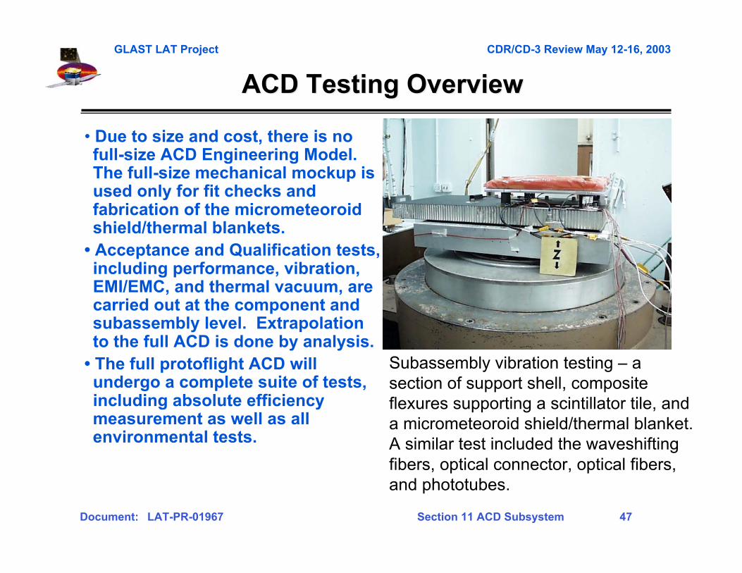
• Due to size and cost, there is nofull-size ACD Engineering Model.The full-size mechanical mockup isused only for fit checks andfabrication of the micrometeoroidshield/thermal blankets.
• Acceptance and Qualification tests,including performance, vibration,EMI/EMC, and thermal vacuum, arecarried out at the component andsubassembly level. Extrapolationto the full ACD is done by analysis.
• The full protoflight ACD willundergo a complete suite of tests,including absolute efficiencymeasurement as well as allenvironmental tests.
Subassembly vibration testing – asection of support shell, compositeflexures supporting a scintillator tile, anda micrometeoroid shield/thermal blanket.A similar test included the waveshiftingfibers, optical connector, optical fibers,and phototubes.
GLAST LAT Project CDR/CD-3 Review May 12-16, 2003
Document: LAT-PR-01967 Section 11 ACD Subsystem 48
Development Environmental Testing Development Environmental Testing –– Tile Shell Assembly Tile Shell Assembly
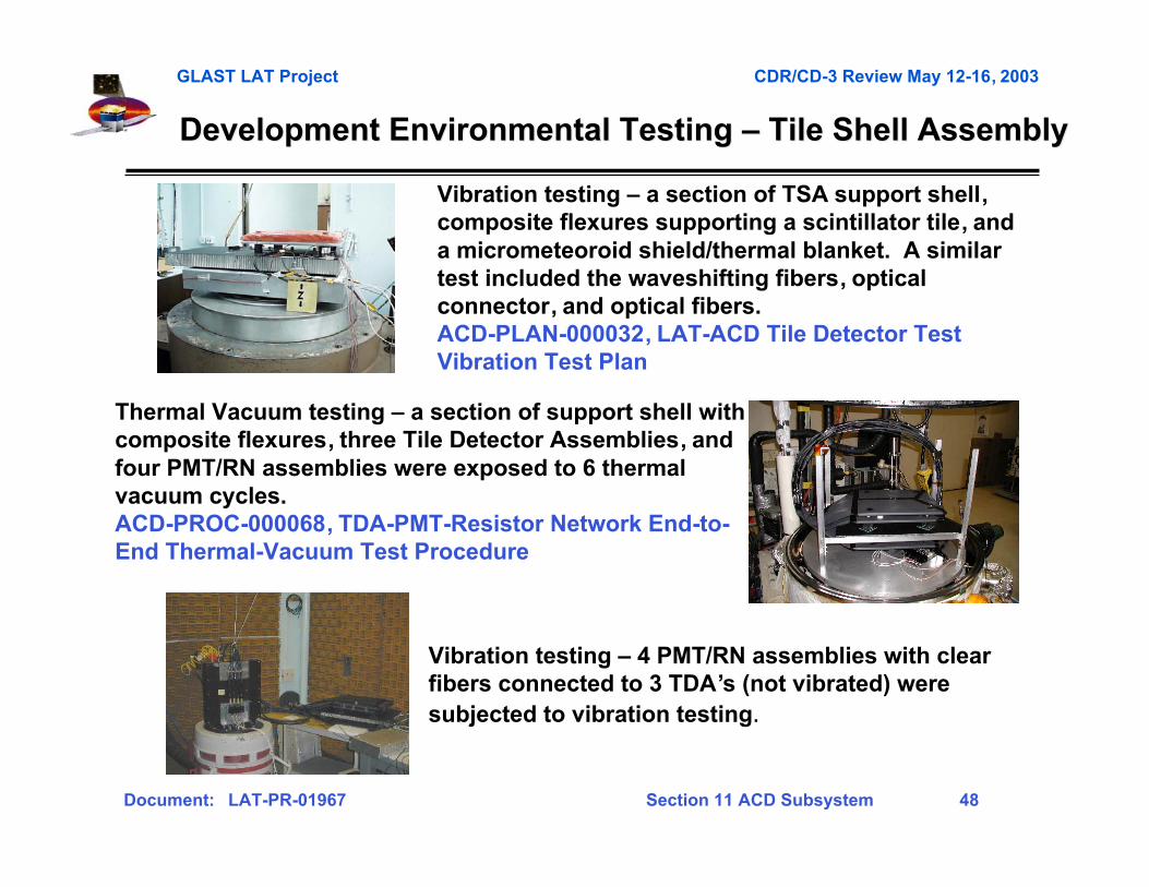
Thermal Vacuum testing – a section of support shell withcomposite flexures, three Tile Detector Assemblies, andfour PMT/RN assemblies were exposed to 6 thermalvacuum cycles.ACD-PROC-000068, TDA-PMT-Resistor Network End-to-End Thermal-Vacuum Test Procedure
Vibration testing – a section of TSA support shell,composite flexures supporting a scintillator tile, anda micrometeoroid shield/thermal blanket. A similartest included the waveshifting fibers, opticalconnector, and optical fibers.ACD-PLAN-000032, LAT-ACD Tile Detector TestVibration Test Plan
Vibration testing – 4 PMT/RN assemblies with clearfibers connected to 3 TDA’s (not vibrated) weresubjected to vibration testing.
GLAST LAT Project CDR/CD-3 Review May 12-16, 2003
Document: LAT-PR-01967 Section 11 ACD Subsystem 49
Development Environmental Testing Development Environmental Testing –– Base Electronics Assembly
A section of the Base Frame Assembly– One Electronics Chassis– Two FREE boards– Four HVBS boards– Up to 36 Phototube assemblies– Mechanical structure
Testing similar to that done for the TSA Engineering Model– Low-level sine– Sine burst– Sine vibration– Random vibration– Mass properties– Interface verification– Electrical functional– 12-cycle thermal vacuum
Scheduled for July/August 2003 (driven by ASIC availability)
GLAST LAT Project CDR/CD-3 Review May 12-16, 2003
Document: LAT-PR-01967 Section 11 ACD Subsystem 50
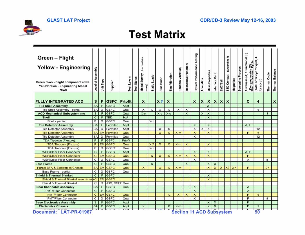
Test MatrixTest Matrix
Leve
l of A
ssem
bly
Uni
t Typ
e
Sup
plie
r
Test
Lev
els
Test
Sta
tus
Mod
al S
urve
y (lo
w le
vel s
ine
surv
ey)
Sta
tic L
oads
Sin
e B
urst
Sin
e V
ibra
tion
Ran
dom
Vib
ratio
n
Mec
hani
cal F
unct
ion/
Opt
ical
Per
form
ance
Tes
ting
Aco
ustic
s
Mas
s P
rope
rtie
s
Inte
rfac
e V
erif.
EM
C/E
MI
ES
D C
ompa
t (G
roun
ding
?)
Mag
netic
s
Scr
eeni
ng P
roce
ss
Aliv
enes
s (A
) / F
unct
iona
l (F)
/ C
ompr
ehen
sive
(C)
Ther
mal
-Vac
uum
Cyc
le
(Tot
al o
f 12
cyc
for
qual
, 4
for
accp
t)
Ther
mal
Cyc
le
Ther
mal
Bal
ance
FULLY INTEGRATED ACD S F GSFC Prtoflt X X ? X X X X X X X C 4 XSA F GSFC Acpt X SA D GSFC Qual X X X X X X X 6S F GSFC Qual X-e X-e X-e X X X ?C F TBD N/A XP D GSFC Qual X-bSA F Fermilab Acpt X X A, FSA S Fermilab Acpt X X X X X 12SA EM Fermilab Qual X X X-m X X F 6
Tile Detector Assembly SA D Fermilab Qual X 12 TDA Tiedown (Flexure) P F GSFC Prtoflt TDA Tiedown (Flexure) P EM GSFC Qual X ? X X X-m X X TDA Tiedown (Flexure) P D GSFC Qual X-b
C F GSFC Acpt X X A, FC EM GSFC Qual X X X X-m X X X F
WSF/Clear Fiber Connector C D GSFC Qual X A 8
C F GSFC Qual X X X XSA EM GSFC Qual X X X X-m X X X X? X? F 2?C D GSFC Qual
Shield & Thermal Blanket C F GSFC X Shield & Thermal Blanket -see remarkC EM GSFC X
C D JSC, GSFC QualClear fiber cable assembly SA F GSFC Qual X A
C F GSFC X AC EM GSFC Qual X X X X F 6
PMT/Fiber Connector C D GSFC Qual X F 8S F GSFC Acpt X X F SA F GSFC Acpt X X X-m X X F 2
Electronics Chassis SA S GSFC Acpt X X ? X X m X X F 12
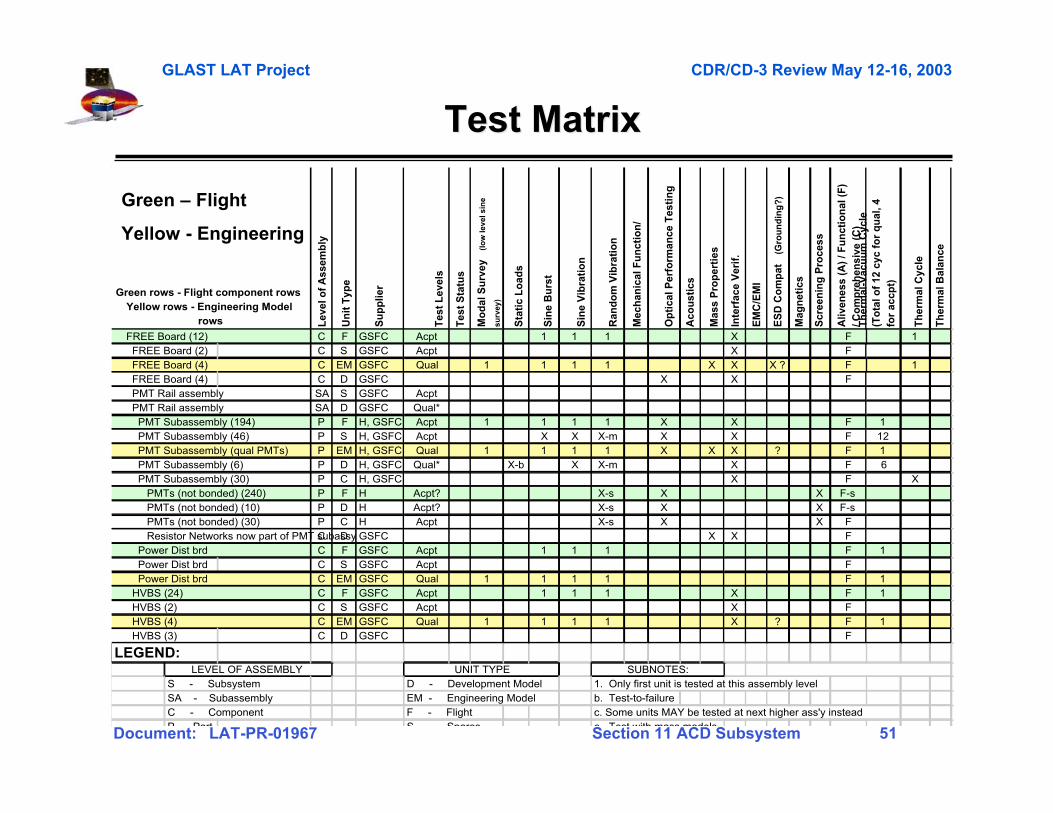
Green rows - Flight component rows Yellow rows - Engineering Model
rows
Tile Shell Assembly Tile Shell Assembly - partial ACD Mechanical Subsystem (no
Partial BFA & Electronics Chassis Base Frame - partial
Shield & Thermal Blanket
PMT/Fiber Connector PMT/Fiber Connector
Base Electronics Assembly Electronics Chassis
Tile Detector Assembly
WSF/Clear Fiber Connector WSF/Clear Fiber Connector
Base Frame
Shell Shell - partial Tile Detector Assembly Tile Detector Assembly
Green – Flight
Yellow - Engineering
GLAST LAT Project CDR/CD-3 Review May 12-16, 2003
Document: LAT-PR-01967 Section 11 ACD Subsystem 51
Test MatrixTest Matrix
Lev
el o
f A
ssem
bly
Un
it T
ype
Su
pp
lier
Tes
t L
evel
s
Tes
t S
tatu
s
Mo
dal
Su
rvey
(l
ow
leve
l sin
e
surv
ey)
Sta
tic
Lo
ads
Sin
e B
urs
t
Sin
e V
ibra
tio
n
Ran
do
m V
ibra
tio
n
Mec
han
ical
Fu
nct
ion
/
Op
tica
l Per
form
ance
Tes
tin
g
Aco
ust
ics
Mas
s P
rop
erti
es
Inte
rfac
e V
erif
.
EM
C/E
MI
ES
D C
om
pat
(G
rou
nd
ing
?)
Mag
net
ics
Scr
een
ing
Pro
cess
Aliv
enes
s (A
) / F
un
ctio
nal
(F
) / C
om
pre
hen
sive
(C
) T
her
mal
-Vac
uu
m C
ycle
(T
ota
l of
12 c
yc f
or
qu
al, 4
fo
r ac
cpt)
Th
erm
al C
ycle
Th
erm
al B
alan
ce
C F GSFC Acpt 1 1 1 X F 1 FREE Board (2) C S GSFC Acpt X F
C EM GSFC Qual 1 1 1 1 X X X ? F 1 FREE Board (4) C D GSFC X X F PMT Rail assembly SA S GSFC Acpt PMT Rail assembly SA D GSFC Qual*
P F H, GSFC Acpt 1 1 1 1 X X F 1 PMT Subassembly (46) P S H, GSFC Acpt X X X-m X X F 12 PMT Subassembly (qual PMTs) P EM H, GSFC Qual 1 1 1 1 X X X ? F 1 PMT Subassembly (6) P D H, GSFC Qual* X-b X X-m X F 6 PMT Subassembly (30) P C H, GSFC X F X PMTs (not bonded) (240) P F H Acpt? X-s X X F-s PMTs (not bonded) (10) P D H Acpt? X-s X X F-s PMTs (not bonded) (30) P C H Acpt X-s X X F Resistor Networks now part of PMT subassyC D GSFC X X F Power Dist brd C F GSFC Acpt 1 1 1 F 1 Power Dist brd C S GSFC Acpt F Power Dist brd C EM GSFC Qual 1 1 1 1 F 1 HVBS (24) C F GSFC Acpt 1 1 1 X F 1
C S GSFC Acpt X F C EM GSFC Qual 1 1 1 1 X ? F 1
HVBS (3) C D GSFC F
LEGEND:
S - Subsystem D - Development Model 1. Only first unit is tested at this assembly levelSA - Subassembly EM - Engineering Model b. Test-to-failureC - Component F - Flight c. Some units MAY be tested at next higher ass'y insteadP Part S Spares e Test with mass models
Green rows - Flight component rows Yellow rows - Engineering Model
rows
UNIT TYPE SUBNOTES:
HVBS (2) HVBS (4)
LEVEL OF ASSEMBLY
FREE Board (12)
FREE Board (4)
PMT Subassembly (194)
Green – Flight
Yellow - Engineering
GLAST LAT Project CDR/CD-3 Review May 12-16, 2003
Document: LAT-PR-01967 Section 11 ACD Subsystem 52
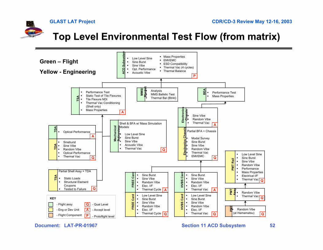
Top Level Environmental Test Flow (from matrix)Top Level Environmental Test Flow (from matrix)
Shell & BFA w/ Mass SimulationModels
� Low Level Sine� Sine Burst� Sine Vibe� Acoustic Vibe� Thermal Vac
Mec
han
ical
Su
bsy
stem
Q
� Sine Burst� Sine Vibe� Random Vibe� Elec. I/F� Thermal Cycle
FR
EE
Car
d
A
� Performance Test� Mass Properties
BE
A
� Low Level Sine� Sine Burst� Sine Vibe� Random Vibe� Performance� Mass Properties� Electrical I/F� Thermal Vac
PM
T R
ail
Q
� Random Vibe� Thermal Vac
PM
TA
ssy
Q
� Random Vibe(at Hamamatsu)
PM
T
Q
� Performance Test� Static Test of Tile Flexures� Tile Flexure NDI� Thermal Vac Conditioning
(Shell only)� Mass Properties
TS
A
A
- Flight assy
- Eng or Dev Unit
- Flight Component
- Qual Level
- Accept levelA
Q
KEY
AC
D S
ub
syst
em
P
� Low Level Sine� Sine Burst� Sine Vibe� Opt. Performance� Acoustic Vibe
� Mass Properties� EMI/EMC� ESD Compatibility� Thermal Vac (4 cycles)� Thermal Balance
� Analysis� MMS Ballstic Test� Thermal Bal (Blnkt)
MM
S/
Bla
nke
t
Partial Shell Assy + TDA
� Static Loads� Structural Element
Coupons� Tested to Failure
TS
A
Q
TD
A
� Sineburst� Sine Vibe� Random Vibe� Optical Performance� Thermal Vac Q
TD
A
� Optical Performance
A
P - Protoflight level
Partial BFA + Chassis
� Modal Survey� Sine Burst� Sine Vibe� Random Vibe� Thermal Vac� EMI/EMC
Ele
ctro
nic
s C
has
sis
Q
� Sine Vibe� Random Vibe� Thermal VacE
lect
ron
ics
Ch
assi
s
A
� Low Level Sine� Sine Burst� Sine Vibe� Random Vibe� Elec. I/F� Thermal Cycle
FR
EE
Car
d
Q
� Sine Burst� Sine Vibe� Random Vibe� Elec. I/F� Thermal Vac
HV
BS
Car
d
A
� Low Level Sine� Sine Burst� Sine Vibe� Random Vibe� Elec. I/F� Thermal Vac
HV
BS
Car
d
Q
Green – Flight
Yellow - Engineering
GLAST LAT Project CDR/CD-3 Review May 12-16, 2003
Document: LAT-PR-01967 Section 11 ACD Subsystem 53
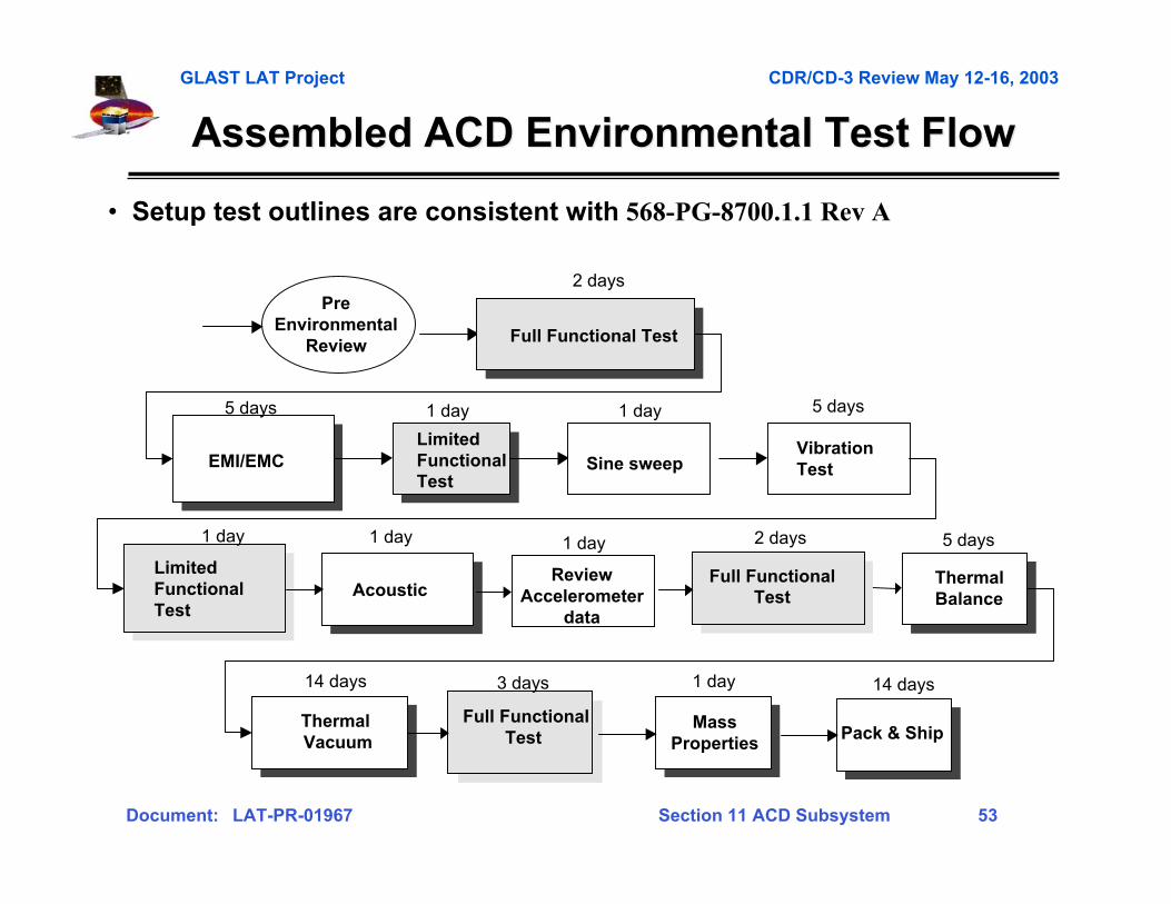
Assembled ACD Environmental Test FlowAssembled ACD Environmental Test Flow
EMI/EMCVibrationTest
Full Functional Test
LimitedFunctionalTest
Thermal Vacuum
Mass Properties
Acoustic
PreEnvironmental
Review
LimitedFunctionalTest
Pack & ShipFull Functional
Test
• Setup test outlines are consistent with 568-PG-8700.1.1 Rev A
2 days
5 days 1 day 5 days
Sine sweep
1 day
1 day 1 day
Full Functional Test
2 days
ThermalBalance
5 days
14 days 3 days 1 day 14 days
ReviewAccelerometer
data
1 day
GLAST LAT Project CDR/CD-3 Review May 12-16, 2003
Document: LAT-PR-01967 Section 11 ACD Subsystem 54
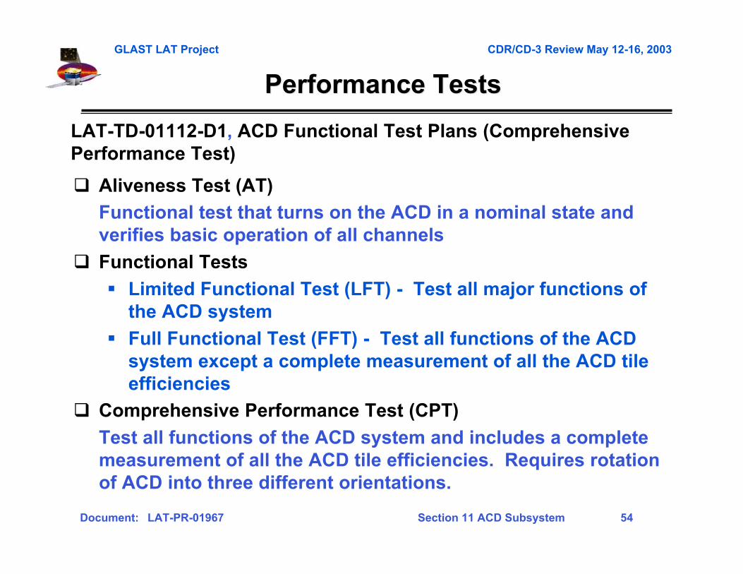
� Aliveness Test (AT)
Functional test that turns on the ACD in a nominal state andverifies basic operation of all channels
� Functional Tests
� Limited Functional Test (LFT) - Test all major functions ofthe ACD system
� Full Functional Test (FFT) - Test all functions of the ACDsystem except a complete measurement of all the ACD tileefficiencies
� Comprehensive Performance Test (CPT)
Test all functions of the ACD system and includes a completemeasurement of all the ACD tile efficiencies. Requires rotationof ACD into three different orientations.
Performance TestsPerformance Tests
LAT-TD-01112-D1, ACD Functional Test Plans (ComprehensivePerformance Test)
GLAST LAT Project CDR/CD-3 Review May 12-16, 2003
Document: LAT-PR-01967 Section 11 ACD Subsystem 55
Gamma-ray LargeGamma-ray LargeArea SpaceArea SpaceTelescopeTelescope
Fabrication ProcessFabrication Process
Section 11-5Section 11-5
GLAST LAT Project CDR/CD-3 Review May 12-16, 2003
Document: LAT-PR-01967 Section 11 ACD Subsystem 56
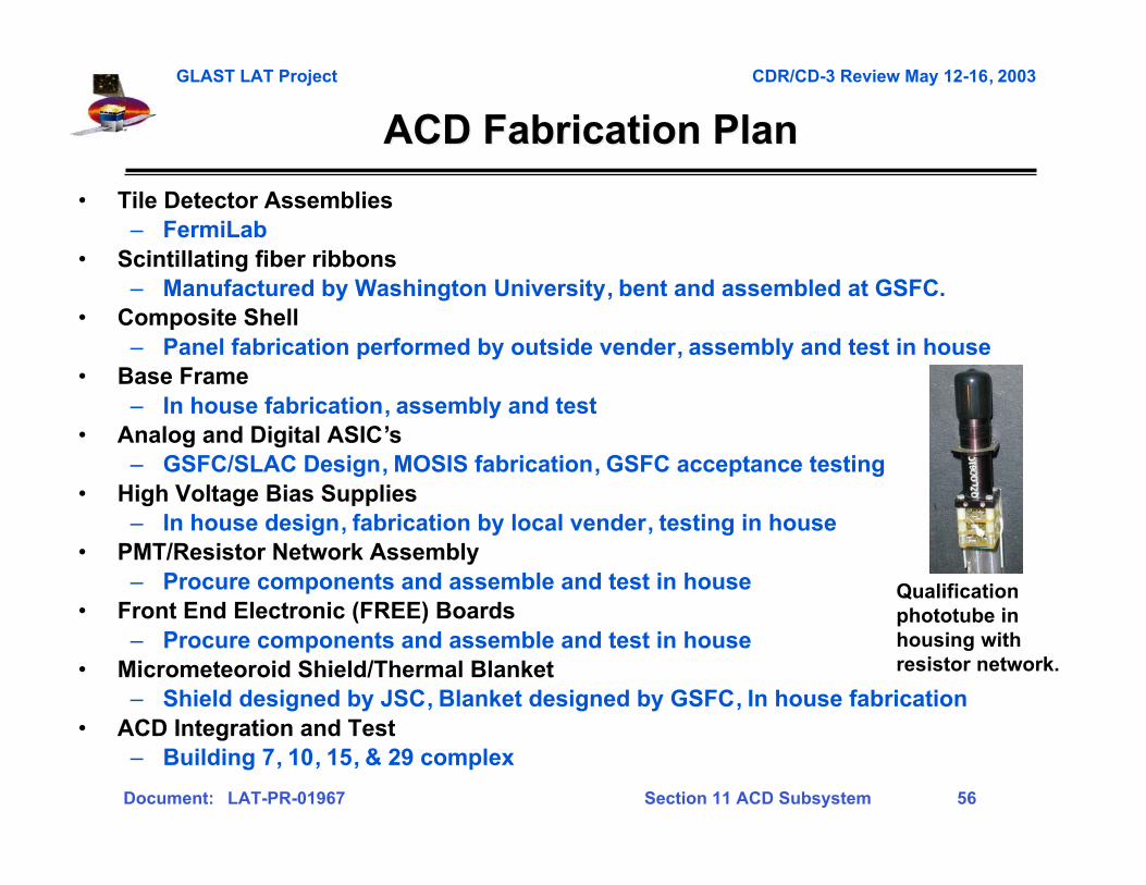
ACD Fabrication PlanACD Fabrication Plan
• Tile Detector Assemblies– FermiLab
• Scintillating fiber ribbons– Manufactured by Washington University, bent and assembled at GSFC.
• Composite Shell– Panel fabrication performed by outside vender, assembly and test in house
• Base Frame– In house fabrication, assembly and test
• Analog and Digital ASIC’s– GSFC/SLAC Design, MOSIS fabrication, GSFC acceptance testing
• High Voltage Bias Supplies– In house design, fabrication by local vender, testing in house
• PMT/Resistor Network Assembly– Procure components and assemble and test in house
• Front End Electronic (FREE) Boards– Procure components and assemble and test in house
• Micrometeoroid Shield/Thermal Blanket– Shield designed by JSC, Blanket designed by GSFC, In house fabrication
• ACD Integration and Test– Building 7, 10, 15, & 29 complex
Qualificationphototube inhousing withresistor network.
GLAST LAT Project CDR/CD-3 Review May 12-16, 2003
Document: LAT-PR-01967 Section 11 ACD Subsystem 57
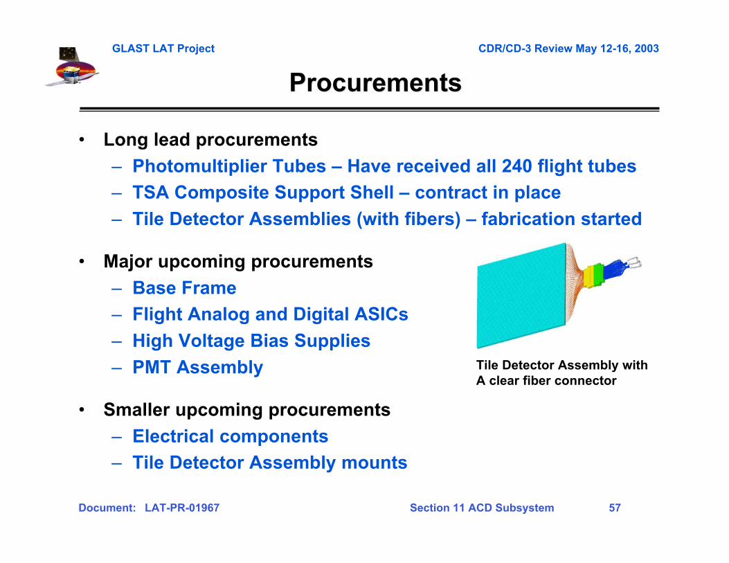
ProcurementsProcurements
• Long lead procurements
– Photomultiplier Tubes – Have received all 240 flight tubes
– TSA Composite Support Shell – contract in place
– Tile Detector Assemblies (with fibers) – fabrication started
• Major upcoming procurements
– Base Frame
– Flight Analog and Digital ASICs
– High Voltage Bias Supplies
– PMT Assembly
• Smaller upcoming procurements
– Electrical components
– Tile Detector Assembly mounts
Tile Detector Assembly withA clear fiber connector

GLAST LAT Project CDR/CD-3 Review May 12-16, 2003
Document: LAT-PR-01967 Section 11 ACD Subsystem 58
TSA Manufacturing FlowTSA Manufacturing Flow
Lay-up skins
Consolidate panels
Thermal cycleblanks
Receiving Inspection
Inspect
Inspect Dry fitshell
Lay-up TileFlexures
Bond Tile Flexure& doublers to panels
Lay-up TileFlexure doublers
Machine flexure& doublers
Inspect
Assemble & BondTSA Panels
Wet lay-upCorner Braids
Inspect
Fab. ShellFlexure fittings
Bond ShellFlexure Fittings
Match DrillFlexure Fittings
Fit Check To BFA
Inspect
Machine flexure& doublers
Inspect
Contracted operations
GSFC code 547
Inspect
Inspections
Receiving Inspection
Receiving Inspection
PANELS FLEXURES
Machine panelblanks
GLAST LAT Project CDR/CD-3 Review May 12-16, 2003
Document: LAT-PR-01967 Section 11 ACD Subsystem 59
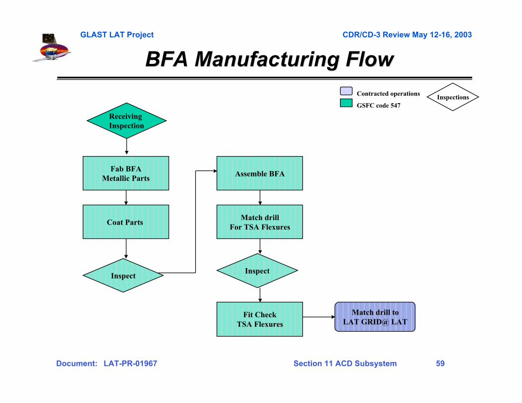
Match drill toLAT GRID@ LAT
Inspect
Fab BFAMetallic Parts
Coat Parts
Assemble BFA
Match drillFor TSA Flexures
Fit CheckTSA Flexures
Inspect
BFA Manufacturing FlowBFA Manufacturing Flow
Receiving Inspection
Contracted operations
GSFC code 547Inspections

GLAST LAT Project CDR/CD-3 Review May 12-16, 2003
Document: LAT-PR-01967 Section 11 ACD Subsystem 60
ACD I&T Assembly/Integration FlowACD I&T Assembly/Integration Flow
• Major activities in I&T flow have been defined (LAT-TD-00430-D1)
Install & Test 17 Rows of TDAs
and fiber cables(5 TDAs per row)
TSASubassembly
IntegrationComplete
ComprehensivePerformance Test (CPT)
PreEnvironmental
Review
Install & Test a 2nd, 3rd, 4th Setof 2 ElectronicChassis (FREE,
HVBS, PMT)
Install Fiber Ribbons
On Tile Shell
Receive FlightQualified Tile Shell
Receive FlightQualified Base
Frame
Install & Test a Setof 2 ElectronicChassis (FREE,HVBS, PMT) on
BFA
BEA Subassembly
IntegrationComplete
Install TSA onto BEA,
Mate & Test Fiber Cables to PMTs
(186 times)
Full Functional
Test
Mate, Install & Test last
4 long Tiles (lower TDAs)
7 days60 days
7 days 21 days
10 days
2 days3 days2 days30 days1 day
InstallMicrometeoroidShield &Thermal Blanket

GLAST LAT Project CDR/CD-3 Review May 12-16, 2003
Document: LAT-PR-01967 Section 11 ACD Subsystem 61
Gamma-ray LargeGamma-ray LargeArea SpaceArea SpaceTelescopeTelescope
Cost and ScheduleCost and Schedule
Section 11-6Section 11-6
GLAST LAT Project CDR/CD-3 Review May 12-16, 2003
Document: LAT-PR-01967 Section 11 ACD Subsystem 62
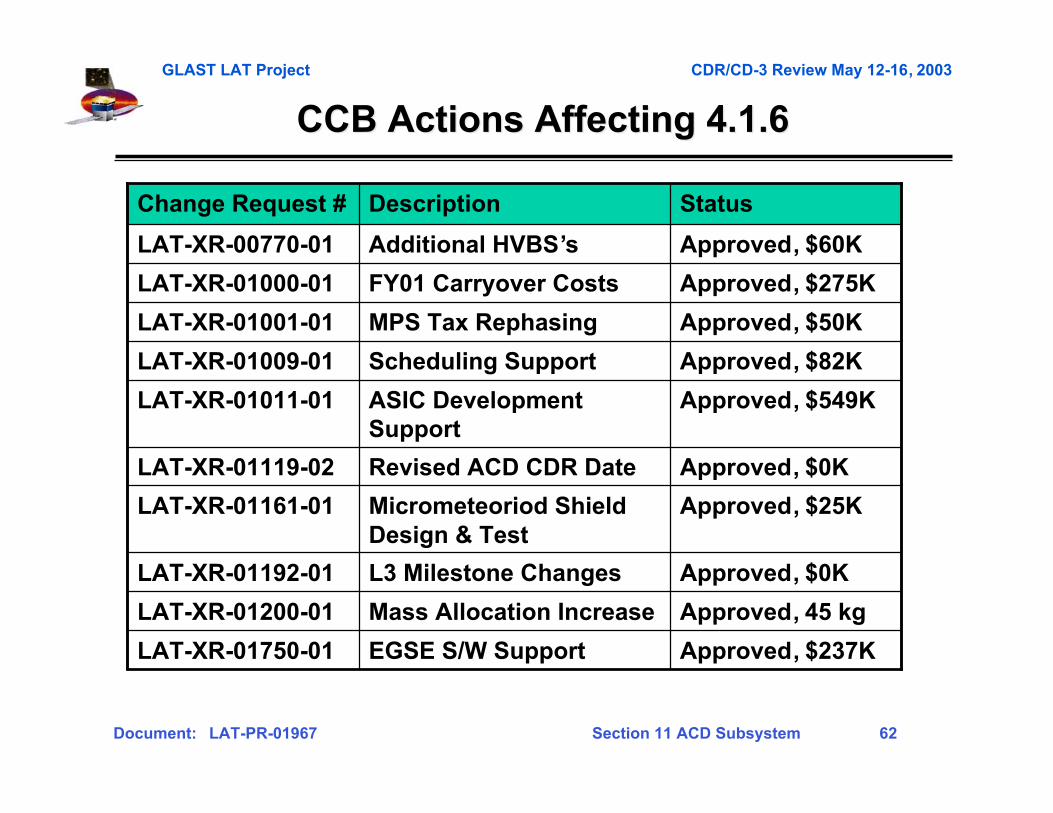
CCB Actions Affecting 4.1.6CCB Actions Affecting 4.1.6
Approved, $237KEGSE S/W SupportLAT-XR-01750-01
Approved, 45 kgMass Allocation IncreaseLAT-XR-01200-01
Approved, $0KL3 Milestone ChangesLAT-XR-01192-01
Approved, $82KScheduling SupportLAT-XR-01009-01
Approved, $549KASIC DevelopmentSupport
LAT-XR-01011-01
Approved, $0KRevised ACD CDR DateLAT-XR-01119-02
Approved, $50KMPS Tax RephasingLAT-XR-01001-01
Approved, $275KFY01 Carryover CostsLAT-XR-01000-01
Approved, $25KMicrometeoriod ShieldDesign & Test
LAT-XR-01161-01
Approved, $60KAdditional HVBS’sLAT-XR-00770-01
StatusDescriptionChange Request #
GLAST LAT Project CDR/CD-3 Review May 12-16, 2003
Document: LAT-PR-01967 Section 11 ACD Subsystem 63
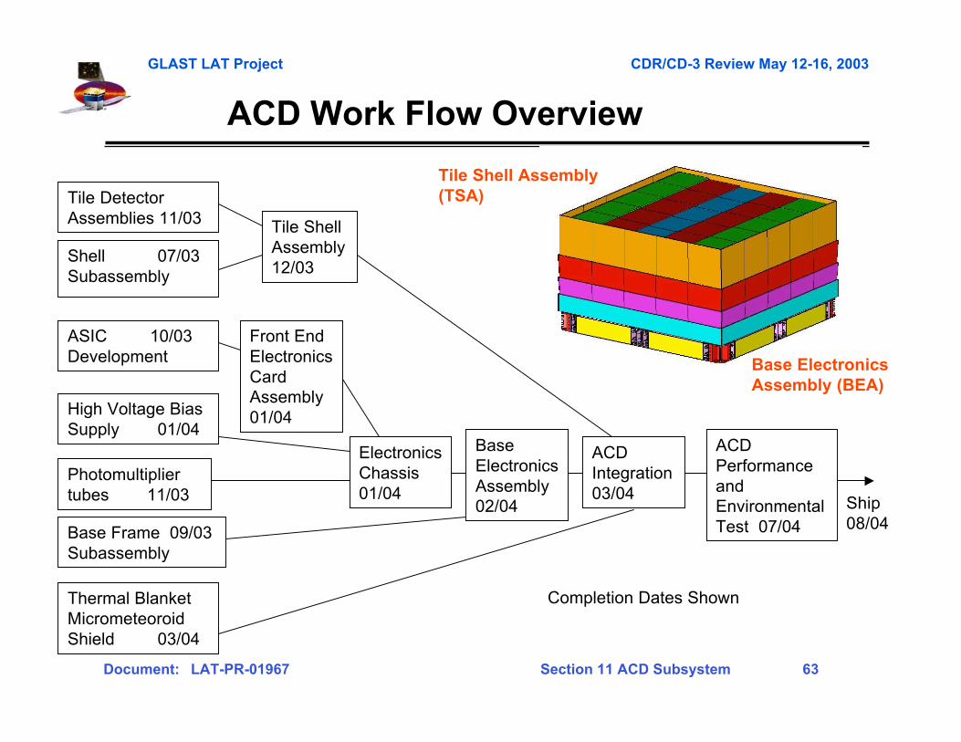
Tile DetectorAssemblies 11/03
Shell 07/03Subassembly
ASIC 10/03Development
High Voltage BiasSupply 01/04
Photomultipliertubes 11/03
Front EndElectronicsCardAssembly01/04
Base Frame 09/03Subassembly
BaseElectronicsAssembly02/04
ACDIntegration03/04
Tile ShellAssembly12/03
ACDPerformanceandEnvironmentalTest 07/04
Thermal BlanketMicrometeoroidShield 03/04
Completion Dates Shown
ACD Work Flow Overview
Ship08/04
Tile Shell Assembly(TSA)
Base ElectronicsAssembly (BEA)
ElectronicsChassis01/04
GLAST LAT Project CDR/CD-3 Review May 12-16, 2003
Document: LAT-PR-01967 Section 11 ACD Subsystem 64
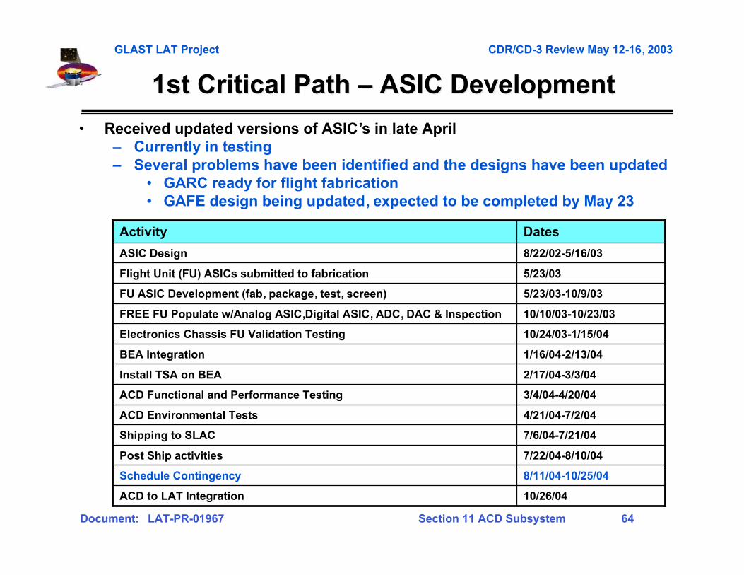
1st Critical Path 1st Critical Path –– ASIC Development ASIC Development
• Received updated versions of ASIC’s in late April– Currently in testing– Several problems have been identified and the designs have been updated
• GARC ready for flight fabrication• GAFE design being updated, expected to be completed by May 23
10/26/04ACD to LAT Integration
8/11/04-10/25/04Schedule Contingency
7/22/04-8/10/04Post Ship activities
7/6/04-7/21/04Shipping to SLAC
4/21/04-7/2/04ACD Environmental Tests
3/4/04-4/20/04ACD Functional and Performance Testing
2/17/04-3/3/04Install TSA on BEA
1/16/04-2/13/04BEA Integration
10/24/03-1/15/04Electronics Chassis FU Validation Testing
10/10/03-10/23/03FREE FU Populate w/Analog ASIC,Digital ASIC, ADC, DAC & Inspection
5/23/03-10/9/03FU ASIC Development (fab, package, test, screen)
5/23/03Flight Unit (FU) ASICs submitted to fabrication
8/22/02-5/16/03ASIC Design
DatesActivity
GLAST LAT Project CDR/CD-3 Review May 12-16, 2003
Document: LAT-PR-01967 Section 11 ACD Subsystem 65
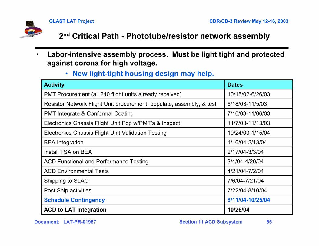
22ndnd Critical Path - Critical Path - Phototube/resistor network assemblyPhototube/resistor network assembly
• Labor-intensive assembly process. Must be light tight and protectedagainst corona for high voltage.
• New light-tight housing design may help.
10/26/04ACD to LAT Integration
8/11/04-10/25/04Schedule Contingency
7/22/04-8/10/04Post Ship activities
7/6/04-7/21/04Shipping to SLAC
4/21/04-7/2/04ACD Environmental Tests
3/4/04-4/20/04ACD Functional and Performance Testing
2/17/04-3/3/04Install TSA on BEA
1/16/04-2/13/04BEA Integration
10/24/03-1/15/04Electronics Chassis Flight Unit Validation Testing
11/7/03-11/13/03Electronics Chassis Flight Unit Pop w/PMT’s & Inspect
7/10/03-11/06/03PMT Integrate & Conformal Coating
6/18/03-11/5/03Resistor Network Flight Unit procurement, populate, assembly, & test
10/15/02-6/26/03PMT Procurement (all 240 flight units already received)
DatesActivity
GLAST LAT Project CDR/CD-3 Review May 12-16, 2003
Document: LAT-PR-01967 Section 11 ACD Subsystem 66
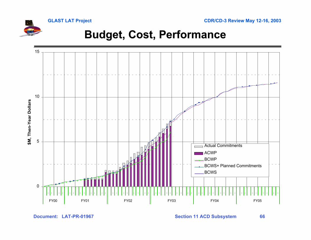
Budget, Cost, PerformanceBudget, Cost, Performance
0
5
10
15
. . . . . . . . . . . . . . . . . . . . . . . . . . . . . . . . . . . . . . . . . . . .
FY00 FY01 FY02 FY03 FY04 FY05
$M
, T
he
n-Y
ea
r D
oll
ars
Actual Commitments
ACWP
BCWP
BCWS+ Planned Commitments
BCWS
GLAST LAT Project CDR/CD-3 Review May 12-16, 2003
Document: LAT-PR-01967 Section 11 ACD Subsystem 67
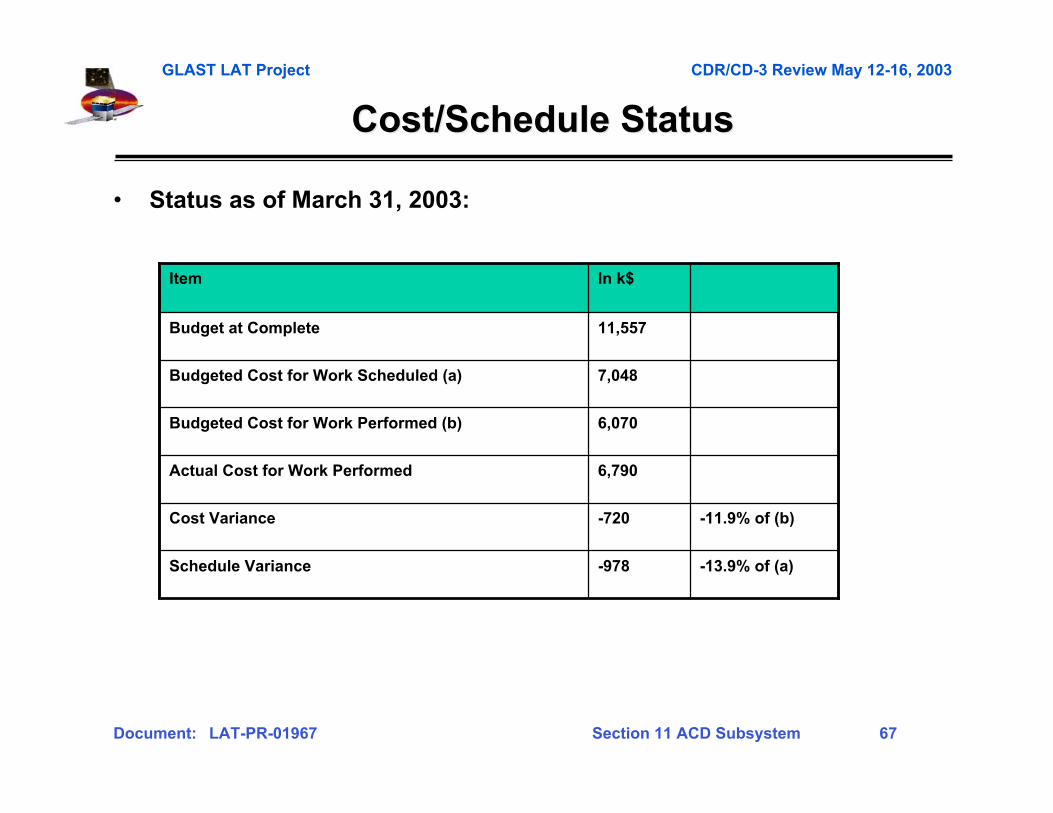
Cost/Schedule StatusCost/Schedule Status
-11.9% of (b)-720Cost Variance
7,048Budgeted Cost for Work Scheduled (a)
6,070Budgeted Cost for Work Performed (b)
6,790Actual Cost for Work Performed
-13.9% of (a)-978Schedule Variance
11,557Budget at Complete
In k$Item
• Status as of March 31, 2003:

GLAST LAT Project CDR/CD-3 Review May 12-16, 2003
Document: LAT-PR-01967 Section 11 ACD Subsystem 68
Gamma-ray LargeGamma-ray LargeArea SpaceArea SpaceTelescopeTelescope
Risk and SummaryRisk and Summary
Section 11-7Section 11-7
GLAST LAT Project CDR/CD-3 Review May 12-16, 2003
Document: LAT-PR-01967 Section 11 ACD Subsystem 69
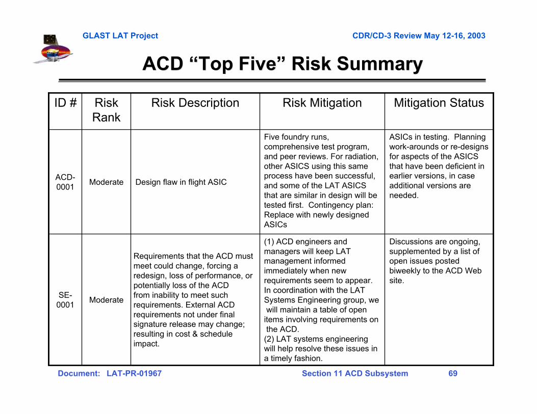
ACD ACD ““Top FiveTop Five”” Risk Summary Risk Summary
(1) ACD engineers andmanagers will keep LATmanagement informedimmediately when newrequirements seem to appear.In coordination with the LATSystems Engineering group, we will maintain a table of openitems involving requirements on the ACD.(2) LAT systems engineeringwill help resolve these issues ina timely fashion.
Five foundry runs,comprehensive test program,and peer reviews. For radiation,other ASICS using this sameprocess have been successful,and some of the LAT ASICSthat are similar in design will betested first. Contingency plan:Replace with newly designedASICs
Risk Mitigation
Discussions are ongoing,supplemented by a list ofopen issues postedbiweekly to the ACD Website.
ASICs in testing. Planningwork-arounds or re-designsfor aspects of the ASICSthat have been deficient inearlier versions, in caseadditional versions areneeded.
Mitigation Status
Requirements that the ACD mustmeet could change, forcing aredesign, loss of performance, orpotentially loss of the ACDfrom inability to meet suchrequirements. External ACDrequirements not under finalsignature release may change;resulting in cost & scheduleimpact.
ModerateSE-
0001
Design flaw in flight ASICModerateACD-0001
Risk DescriptionRiskRank
ID #
GLAST LAT Project CDR/CD-3 Review May 12-16, 2003
Document: LAT-PR-01967 Section 11 ACD Subsystem 70
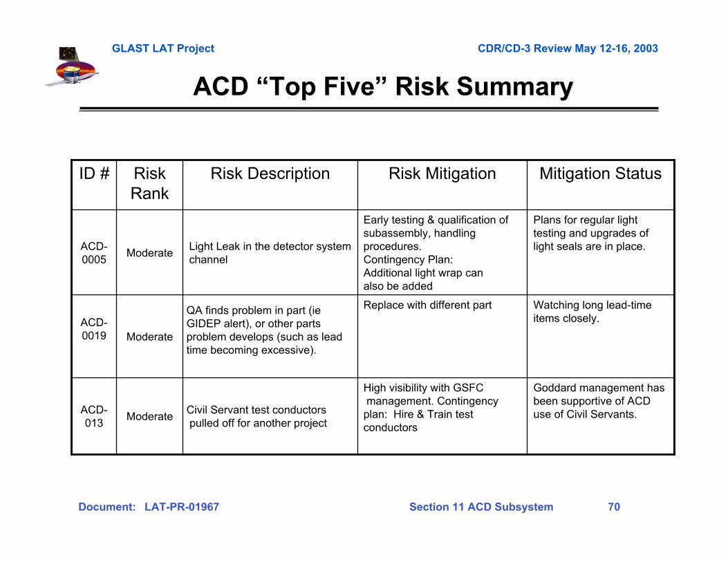
ACD ACD ““Top FiveTop Five”” Risk Summary Risk Summary
Watching long lead-timeitems closely.
Replace with different partQA finds problem in part (ieGIDEP alert), or other partsproblem develops (such as leadtime becoming excessive).
ModerateACD-0019
High visibility with GSFC management. Contingencyplan: Hire & Train testconductors
Early testing & qualification ofsubassembly, handlingprocedures.Contingency Plan:Additional light wrap canalso be added
Risk Mitigation
Goddard management hasbeen supportive of ACDuse of Civil Servants.
Plans for regular lighttesting and upgrades oflight seals are in place.
Mitigation Status
Civil Servant test conductors pulled off for another project
ModerateACD-013
Light Leak in the detector systemchannel
ModerateACD-0005
Risk DescriptionRiskRank
ID #
GLAST LAT Project CDR/CD-3 Review May 12-16, 2003
Document: LAT-PR-01967 Section 11 ACD Subsystem 71
SummarySummary
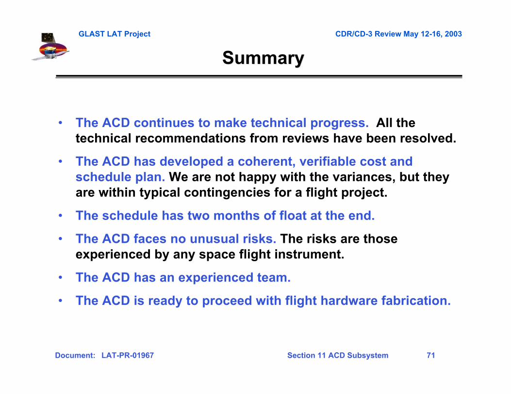
• The ACD continues to make technical progress. All thetechnical recommendations from reviews have been resolved.
• The ACD has developed a coherent, verifiable cost andschedule plan. We are not happy with the variances, but theyare within typical contingencies for a flight project.
• The schedule has two months of float at the end.
• The ACD faces no unusual risks. The risks are thoseexperienced by any space flight instrument.
• The ACD has an experienced team.
• The ACD is ready to proceed with flight hardware fabrication.
GLAST LAT Project CDR/CD-3 Review May 12-16, 2003
Document: LAT-PR-01967 Section 11 ACD Subsystem 72
Gamma-ray LargeGamma-ray LargeArea SpaceArea SpaceTelescopeTelescope
Appendix AAppendix ARequirementsRequirements(some duplication of main(some duplication of mainpresentation forpresentation forcompleteness)completeness)
GLAST LAT Project CDR/CD-3 Review May 12-16, 2003
Document: LAT-PR-01967 Section 11 ACD Subsystem 73
Level III Key Requirements SummaryLevel III Key Requirements Summary
Parameter Requirement Expected Performance Verification Method
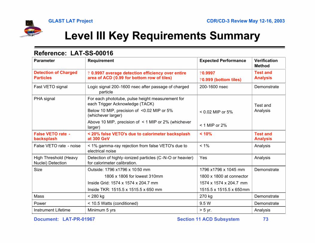
Detection of Charged Particles
? 0.9997 average detection efficiency over entire area of ACD (0.99 for bottom row of tiles)
?0.9997
?0.999 (bottom tiles)
Test and Analysis
Fast VETO signal Logic signal 200-1600 nsec after passage of charged particle
200-1600 nsec Demonstrate
PHA signal For each phototube, pulse height measurement for each Trigger Acknowledge (TACK)
Below 10 MIP, precision of <0.02 MIP or 5% (whichever larger)
Above 10 MIP, precision of < 1 MIP or 2% (whichever larger)
< 0.02 MIP or 5%
< 1 MIP or 2%
Test and Analysis
False VETO rate - backsplash
< 20% false VETO's due to calorimeter backsplash at 300 GeV
< 10% Test and Analysis
False VETO rate - noise < 1% gamma-ray rejection from false VETO's due to electrical noise
< 1% Analysis
High Threshold (Heavy Nuclei) Detection
Detection of highly-ionized particles (C -N-O or heavier) for calorimeter calibration.
Yes Analysis
Size Outside: 1796 x1796 x 10 50 mm
1806 x 1806 for lowest 310mm
Inside Grid: 1574 x 1574 x 204.7 mm
Inside TKR: 1515.5 x 1515.5 x 650 mm
1796 x1796 x 1045 mm
1800 x 1800 at connector
1574 x 1574 x 204.7 mm
1515.5 x 1515.5 x 650mm
Demonstrate
Mass < 280 kg 270 kg Demonstrate
Power < 10.5 Watts (conditioned) 9.5 W Demonstrate
Instrument Lifetime Minimum 5 yrs > 5 yr. Analysis
Reference: LAT-SS-00016

GLAST LAT Project CDR/CD-3 Review May 12-16, 2003
Document: LAT-PR-01967 Section 11 ACD Subsystem 74
FlowdownFlowdown - Requirements to Design - Requirements to DesignParameter Requirement Constraints Characteristics Needed Design
Detection of Charged Particles
ACD-SS-00016
ACD3-20
? 0.9997 average detection efficiency over entire area of ACD (less for bottom row of tiles)
Mass
Power
Size
Lifetime
Minimize inert material outside active detector
Low backsplash sensitivity
High-sensitivity charged particle detector
No gaps
Low energy threshold for high efficiency
Performance margin to compensate for aging
False VETO rate – backsplash
ACD-SS-00016
ACD3-26
< 20% false VETO's due to calorimeter backsplash at 300 GeV
High charged particle detection efficiency
Mass
Power
Size
Lifetime
Detector with low sensitivity to soft photons
Segmentation < 1000 cm2
High energy threshold (backsplash is soft)
Plastic scintillator tiles, 1 cm thick, < 1000 cm2 size
Waveshifting fiber light collection, with clear fibers for transmission in long runs
Overlap one dimension, seal other with scintillating fiber ribbons
Photomultiplier tubes, with gain set low at start of mission to allow increase as tube ages.
Low-noise electronics
Threshold well below MIP peak but above most of backsplash
Particlesseen in ACD
Backsplash/noise
GLAST LAT Project CDR/CD-3 Review May 12-16, 2003
Document: LAT-PR-01967 Section 11 ACD Subsystem 75
Tracker
Calorimeter
Tracker
Calorimeter
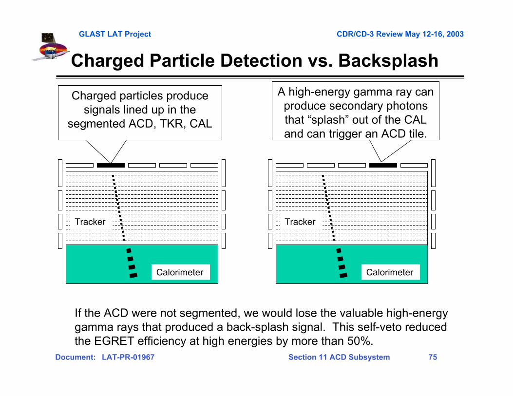
Charged particles producesignals lined up in the
segmented ACD, TKR, CAL
A high-energy gamma ray canproduce secondary photonsthat “splash” out of the CALand can trigger an ACD tile.
If the ACD were not segmented, we would lose the valuable high-energygamma rays that produced a back-splash signal. This self-veto reducedthe EGRET efficiency at high energies by more than 50%.
Charged Particle Detection vs. Backsplash
GLAST LAT Project CDR/CD-3 Review May 12-16, 2003
Document: LAT-PR-01967 Section 11 ACD Subsystem 76
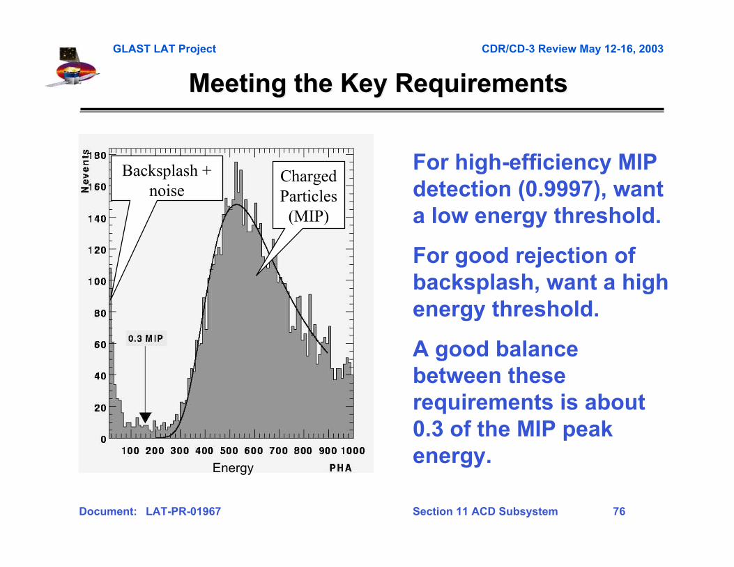
Meeting the Key RequirementsMeeting the Key Requirements
ChargedParticles
(MIP)
Backsplash +noise
For high-efficiency MIPdetection (0.9997), wanta low energy threshold.
For good rejection ofbacksplash, want a highenergy threshold.
A good balancebetween theserequirements is about0.3 of the MIP peakenergy.
Energy

GLAST LAT Project CDR/CD-3 Review May 12-16, 2003
Document: LAT-PR-01967 Section 11 ACD Subsystem 77
Level IV Requirements OutlineLevel IV Requirements Outline
5.2 Charged Particle Detection5.3 Adjustable Threshold on VETO Detection of Charged Particles5.4 False VETO due to Electrical Noise5.5 High-Threshold Detection5.6 Adjustable High-Threshold5.7 Level 1 Trigger Acknowledge (TACK)5.8 Signals - (8 lower level requirements)5.9 ACD Performance Monitoring - (10 lower level requirements)5.10 High Voltage Bias Supply - (14 lower level requirements)5.11 PMT - (6 lower level requirements)5.12 Radiation Tolerance - (2 lower level requirements)5.13 Reliability - (6 lower level requirements)5.14 Commands - (10 lower level requirements)5.15 Output Data Formats5.16 Power Consumption5.17 Total ACD Mass5.18 Environmental Requirements - (11 lower level requirements)5.19 Performance Life5.20 Rate Requirement for Operation within Specification5.21 Testability5.22 Center of Mass5.23 Volume5.24 Instrument Coverage5.25 LAT to ACD Gap.5.26 Material interaction of gamma radiation (Gamma radiation due to ACD material interactions)5.27 Thermal Blanket/ Micrometeoroid Shield Areal Mass Density5.28 Gaps between scintillating tiles5.29 Light Throughput
GLAST LAT Project CDR/CD-3 Review May 12-16, 2003
Document: LAT-PR-01967 Section 11 ACD Subsystem 78
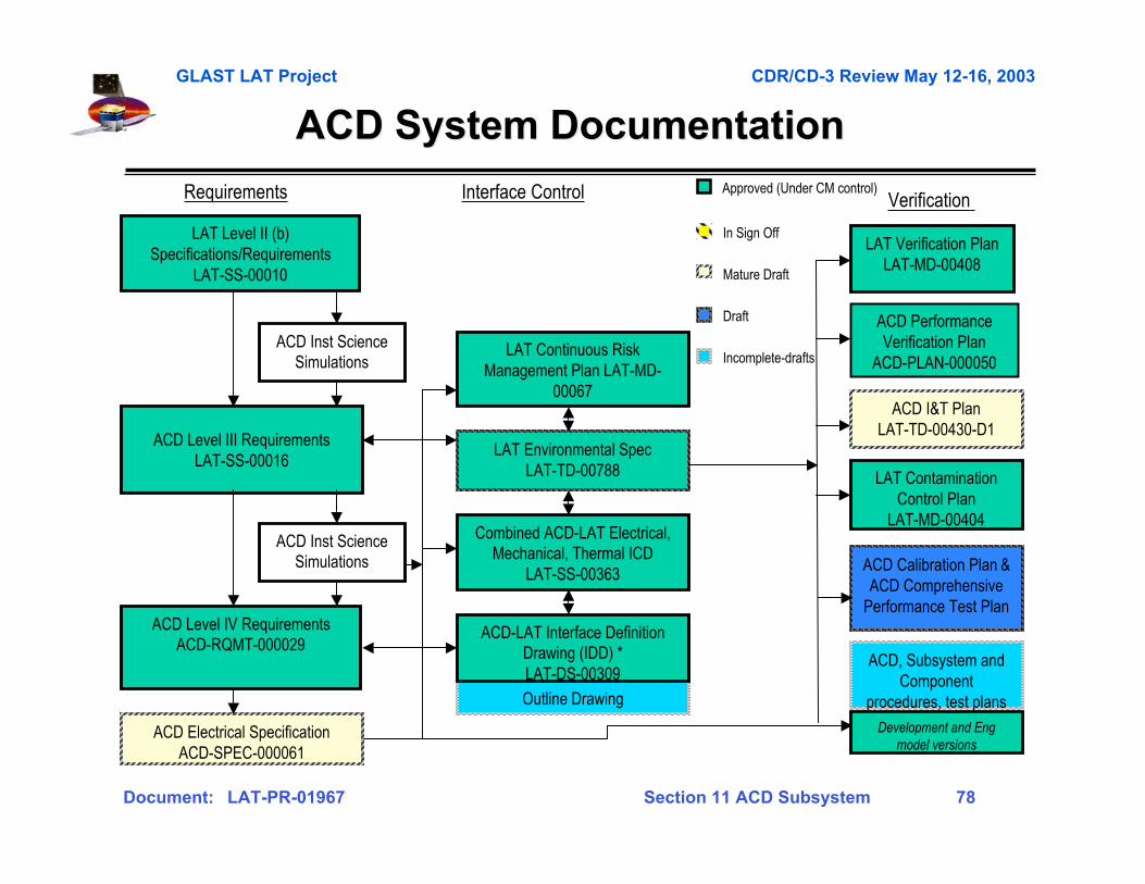
ACD System Documentation ACD System Documentation
Requirements Interface Control Approved (Under CM control)
Outline Drawing
ACD Electrical SpecificationACD-SPEC-000061
ACD Level III RequirementsLAT-SS-00016
LAT Verification PlanLAT-MD-00408
ACD PerformanceVerification Plan
ACD-PLAN-000050
ACD I&T PlanLAT-TD-00430-D1
Verification
ACD Level IV RequirementsACD-RQMT-000029
LAT Level II (b)Specifications/Requirements
LAT-SS-00010
ACD Calibration Plan &ACD Comprehensive
Performance Test Plan
Draft
In Sign Off
Mature Draft
Incomplete-drafts
LAT ContaminationControl Plan
LAT-MD-00404Combined ACD-LAT Electrical,
Mechanical, Thermal ICDLAT-SS-00363
ACD-LAT Interface DefinitionDrawing (IDD) *LAT-DS-00309
LAT Environmental SpecLAT-TD-00788
ACD Inst ScienceSimulations
ACD Inst ScienceSimulations
LAT Continuous RiskManagement Plan LAT-MD-
00067
Development and Engmodel versions
ACD, Subsystem andComponent
procedures, test plans
GLAST LAT Project CDR/CD-3 Review May 12-16, 2003
Document: LAT-PR-01967 Section 11 ACD Subsystem 79
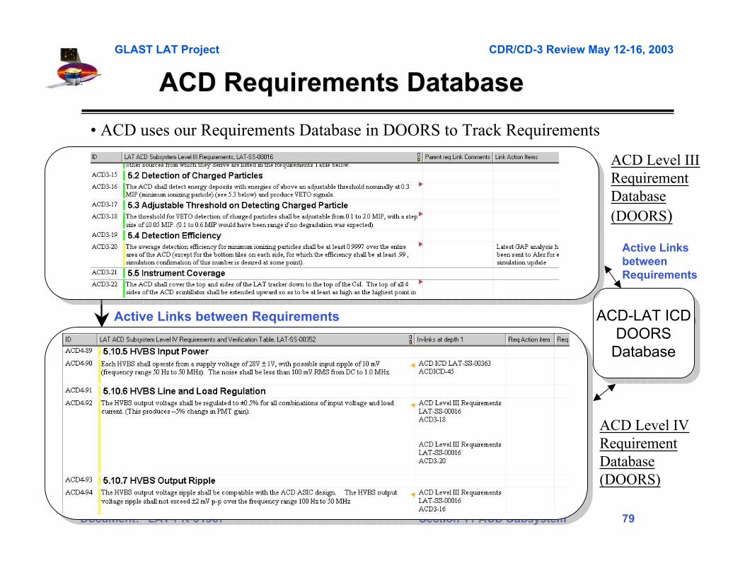
ACD Requirements Database ACD Requirements Database
ACD Level IIIRequirementDatabase(DOORS)
ACD Level IVRequirementDatabase(DOORS)
ACD-LAT ICD DOORS Database
ACD-LAT ICD DOORS Database
Active Links between Requirements
Active LinksbetweenRequirements
• ACD uses our Requirements Database in DOORS to Track Requirements
Screen capture of level IV doors tableScreen capture of level IV doors table

GLAST LAT Project CDR/CD-3 Review May 12-16, 2003
Document: LAT-PR-01967 Section 11 ACD Subsystem 80
Gamma-ray LargeGamma-ray LargeArea SpaceArea SpaceTelescopeTelescope
Appendix BAppendix BFabricationFabrication(some duplication of main(some duplication of mainpresentation forpresentation forcompleteness)completeness)

GLAST LAT Project CDR/CD-3 Review May 12-16, 2003
Document: LAT-PR-01967 Section 11 ACD Subsystem 81
ACD Fabrication PlanACD Fabrication Plan
• Tile Detector Assemblies– FermiLab
• Scintillating fiber ribbons– Manufactured by Washington University, bent and assembled at GSFC.
• Composite Shell– Panel fabrication performed by outside vender, assembly and test in house
• Base Frame– In house fabrication, assembly and test
• Analog and Digital ASIC’s– GSFC/SLAC Design, MOSIS fabrication, GSFC acceptance testing
• High Voltage Bias Supplies– In house design, fabrication by local vender, testing in house
• PMT/Resistor Network Assembly– Procure components and assemble and test in house
• Front End Electronic (FREE) Boards– Procure components and assemble and test in house
• Micrometeoroid Shield/Thermal Blanket– Shield designed by JSC, Blanket designed by GSFC, In house fabrication
• ACD Integration and Test– Building 7, 10, 15, & 29 complex
Qualificationphototube inhousing withresistor network.
GLAST LAT Project CDR/CD-3 Review May 12-16, 2003
Document: LAT-PR-01967 Section 11 ACD Subsystem 82
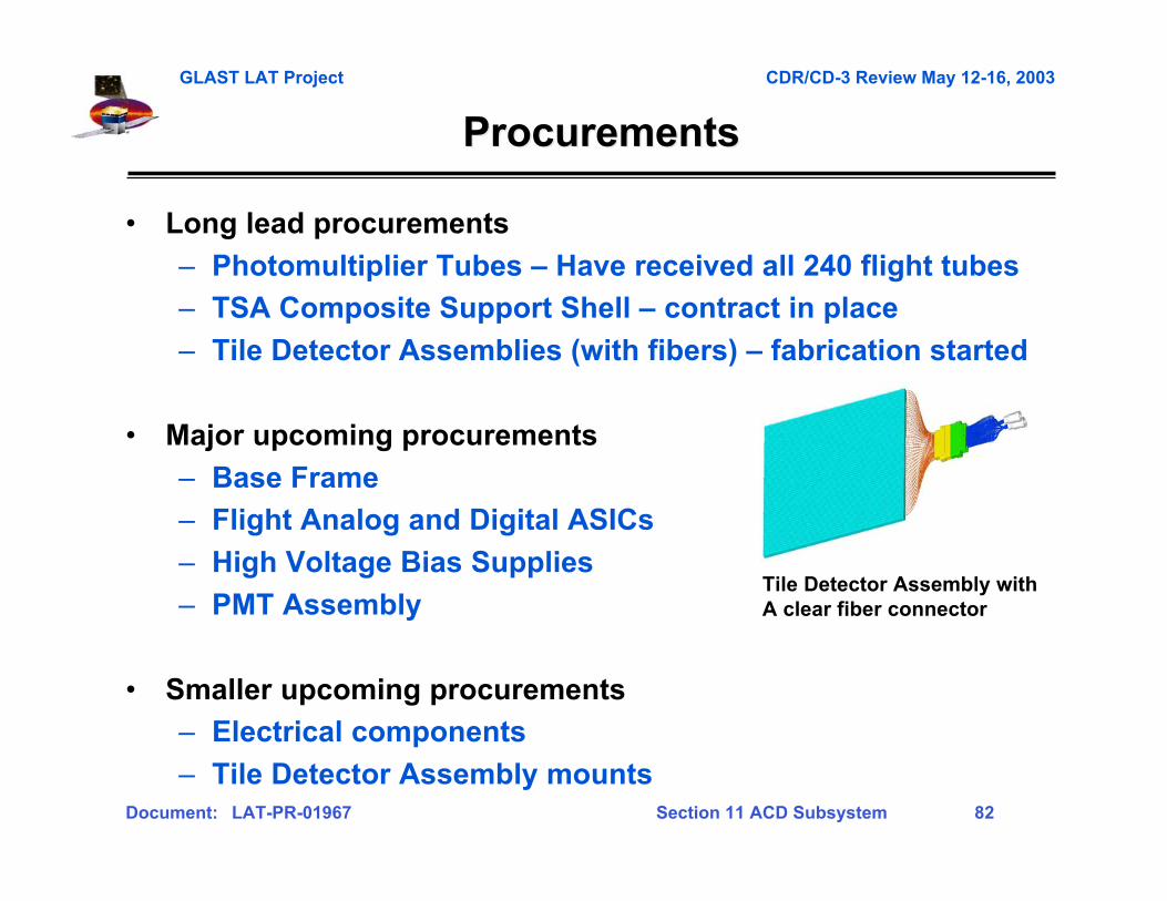
ProcurementsProcurements
• Long lead procurements
– Photomultiplier Tubes – Have received all 240 flight tubes
– TSA Composite Support Shell – contract in place
– Tile Detector Assemblies (with fibers) – fabrication started
• Major upcoming procurements
– Base Frame
– Flight Analog and Digital ASICs
– High Voltage Bias Supplies
– PMT Assembly
• Smaller upcoming procurements
– Electrical components
– Tile Detector Assembly mounts
Tile Detector Assembly withA clear fiber connector
GLAST LAT Project CDR/CD-3 Review May 12-16, 2003
Document: LAT-PR-01967 Section 11 ACD Subsystem 83
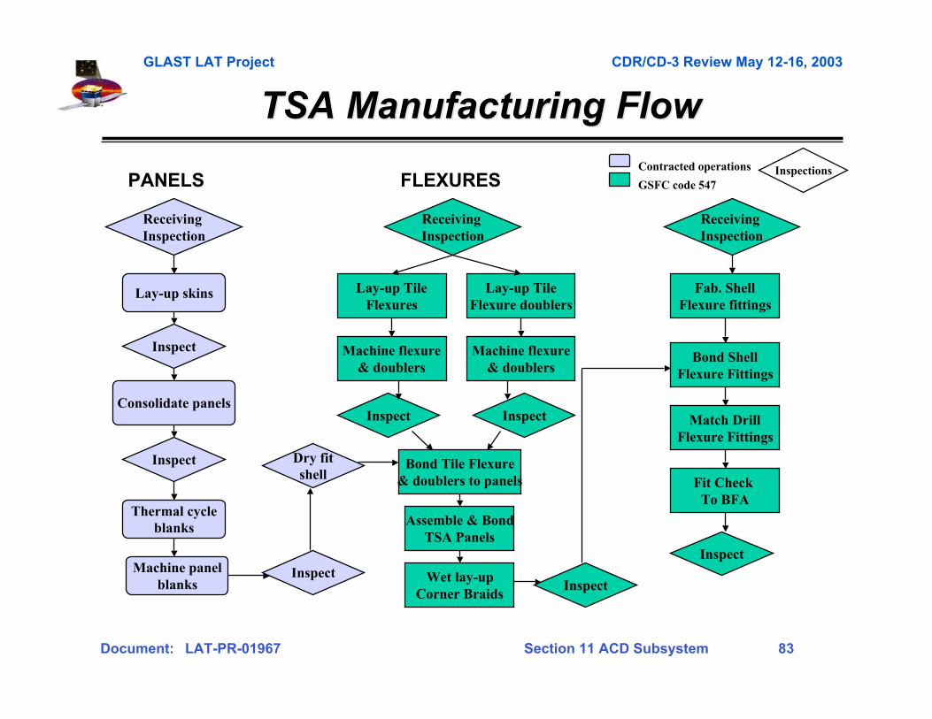
TSA Manufacturing FlowTSA Manufacturing Flow
Lay-up skins
Consolidate panels
Thermal cycleblanks
Receiving Inspection
Inspect
Inspect Dry fitshell
Lay-up TileFlexures
Bond Tile Flexure& doublers to panels
Lay-up TileFlexure doublers
Machine flexure& doublers
Inspect
Assemble & BondTSA Panels
Wet lay-upCorner Braids
Inspect
Fab. ShellFlexure fittings
Bond ShellFlexure Fittings
Match DrillFlexure Fittings
Fit Check To BFA
Inspect
Machine flexure& doublers
Inspect
Contracted operations
GSFC code 547
Inspect
Inspections
Receiving Inspection
Receiving Inspection
PANELS FLEXURES
Machine panelblanks

GLAST LAT Project CDR/CD-3 Review May 12-16, 2003
Document: LAT-PR-01967 Section 11 ACD Subsystem 84
Match drill toLAT GRID@ LAT
Inspect
Fab BFAMetallic Parts
Coat Parts
Assemble BFA
Match drillFor TSA Flexures
Fit CheckTSA Flexures
Inspect
BFA Manufacturing FlowBFA Manufacturing Flow
Receiving Inspection
Contracted operations
GSFC code 547Inspections
GLAST LAT Project CDR/CD-3 Review May 12-16, 2003
Document: LAT-PR-01967 Section 11 ACD Subsystem 85
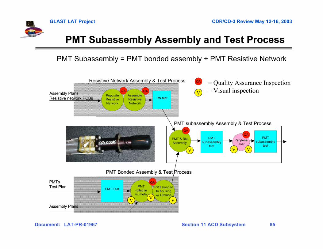
PMT Subassembly Assembly and Test ProcessPMT Subassembly Assembly and Test Process
Assembly PlansResistive network PCBs
PopulateResistiveNetwork
QA
RN test
QAAssembleResistiveNetwork
Resistive Network Assembly & Test Process
PMT TestPMT
rolled inmumetal
PMT bondedto housingw/ Uralane
Assembly Plans
QAPMTsTest Plan
V VV
PMT Bonded Assembly & Test Process
PMT & RNAssembly
PMTsubassembly
test
QA
V
ParyleneCoat
QA
V V
PMT subassembly Assembly & Test Process
PMTsubassembly
test
PMT Subassembly = PMT bonded assembly + PMT Resistive Network
= Quality Assurance Inspection= Visual inspectionV
QA
GLAST LAT Project CDR/CD-3 Review May 12-16, 2003
Document: LAT-PR-01967 Section 11 ACD Subsystem 86
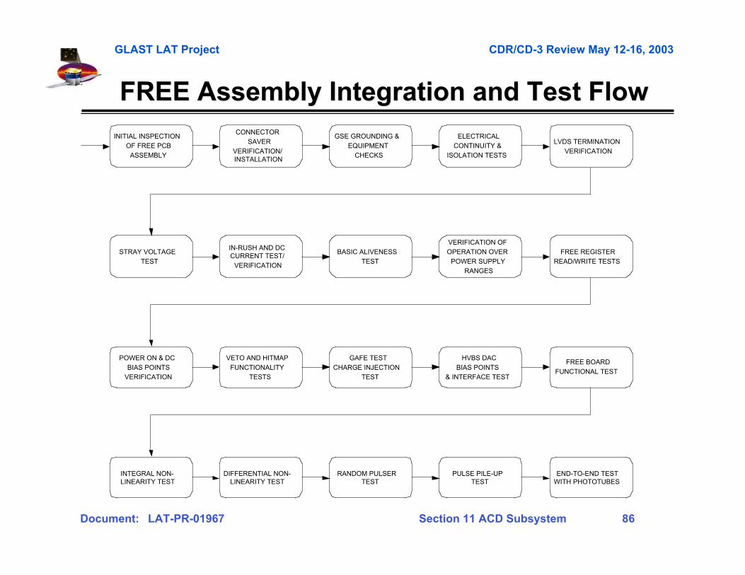
FREE Assembly Integration and Test FlowFREE Assembly Integration and Test Flow
INITIAL INSPECTIONOF FREE PCB
ASSEMBLY
CONNECTORSAVER
VERIFICATION/INSTALLATION
GSE GROUNDING &EQUIPMENT
CHECKS
ELECTRICALCONTINUITY &
ISOLATION TESTS
LVDS TERMINATIONVERIFICATION
IN-RUSH AND DCCURRENT TEST/
VERIFICATION
BASIC ALIVENESSTEST
STRAY VOLTAGETEST
VERIFICATION OFOPERATION OVER
POWER SUPPLYRANGES
FREE REGISTERREAD/WRITE TESTS
POWER ON & DCBIAS POINTS
VERIFICATION
VETO AND HITMAPFUNCTIONALITY
TESTS
GAFE TESTCHARGE INJECTION
TEST
HVBS DACBIAS POINTS
& INTERFACE TEST
FREE BOARDFUNCTIONAL TEST
RANDOM PULSERTEST
PULSE PILE-UPTEST
END-TO-END TESTWITH PHOTOTUBES
DIFFERENTIAL NON-LINEARITY TEST
INTEGRAL NON-LINEARITY TEST
GLAST LAT Project CDR/CD-3 Review May 12-16, 2003
Document: LAT-PR-01967 Section 11 ACD Subsystem 87
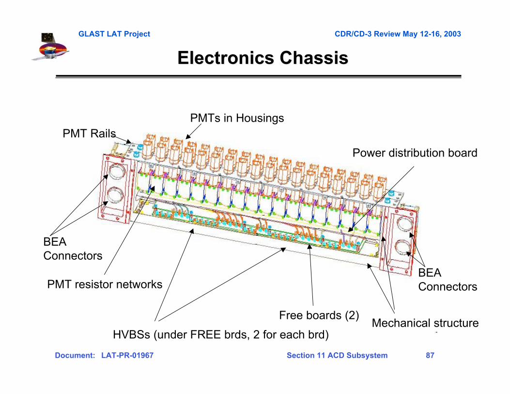
Electronics ChassisElectronics Chassis
• Electronics Chassis
PMTs in Housings
PMT resistor networks
Free boards (2)
PMT Rails
HVBSs (under FREE brds, 2 for each brd)
Power distribution board
Mechanical structure
BEA Connectors
BEA Connectors
GLAST LAT Project CDR/CD-3 Review May 12-16, 2003
Document: LAT-PR-01967 Section 11 ACD Subsystem 88
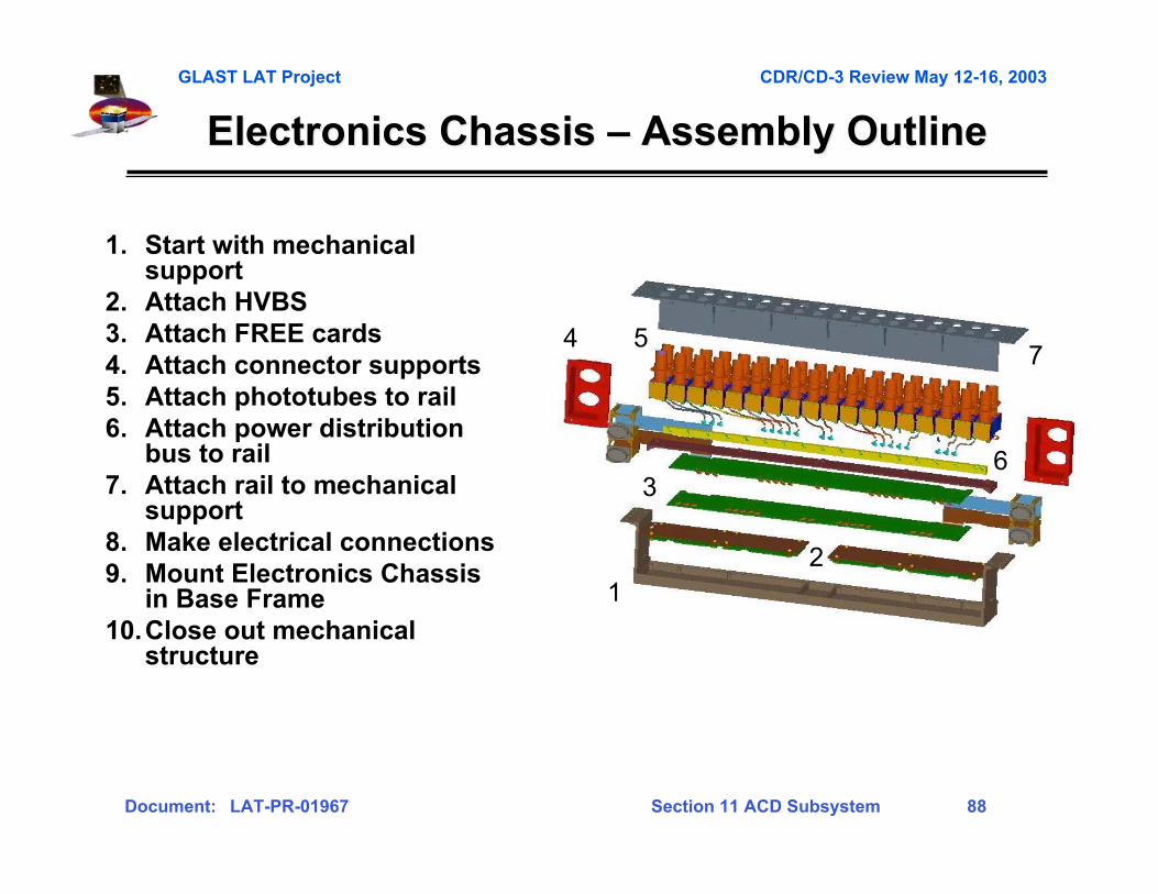
Electronics Chassis Electronics Chassis –– Assembly Outline Assembly Outline
1. Start with mechanicalsupport
2. Attach HVBS3. Attach FREE cards4. Attach connector supports5. Attach phototubes to rail6. Attach power distribution
bus to rail7. Attach rail to mechanical
support8. Make electrical connections9. Mount Electronics Chassis
in Base Frame10.Close out mechanical
structure
21
4
36
57
GLAST LAT Project CDR/CD-3 Review May 12-16, 2003
Document: LAT-PR-01967 Section 11 ACD Subsystem 89
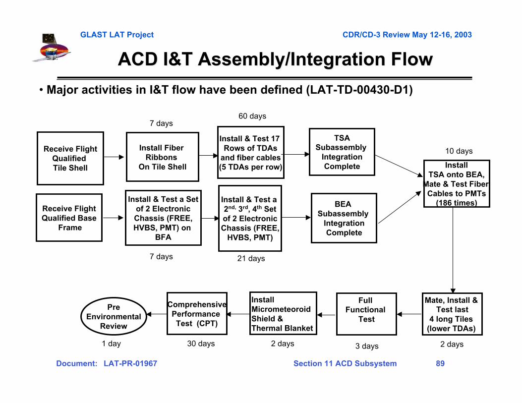
ACD I&T Assembly/Integration FlowACD I&T Assembly/Integration Flow
• Major activities in I&T flow have been defined (LAT-TD-00430-D1)
Install & Test 17 Rows of TDAs
and fiber cables(5 TDAs per row)
TSASubassembly
IntegrationComplete
ComprehensivePerformance Test (CPT)
PreEnvironmental
Review
Install & Test a 2nd, 3rd, 4th Setof 2 ElectronicChassis (FREE,
HVBS, PMT)
Install Fiber Ribbons
On Tile Shell
Receive FlightQualified Tile Shell
Receive FlightQualified Base
Frame
Install & Test a Setof 2 ElectronicChassis (FREE,HVBS, PMT) on
BFA
BEA Subassembly
IntegrationComplete
Install TSA onto BEA,
Mate & Test Fiber Cables to PMTs
(186 times)
Full Functional
Test
Mate, Install & Test last
4 long Tiles (lower TDAs)
7 days60 days
7 days 21 days
10 days
2 days3 days2 days30 days1 day
InstallMicrometeoroidShield &Thermal Blanket
GLAST LAT Project CDR/CD-3 Review May 12-16, 2003
Document: LAT-PR-01967 Section 11 ACD Subsystem 90
Gamma-ray LargeGamma-ray LargeArea SpaceArea SpaceTelescopeTelescope
Appendix CAppendix C
Peer Review Peer Review RFAsRFAs

GLAST LAT Project CDR/CD-3 Review May 12-16, 2003
Document: LAT-PR-01967 Section 11 ACD Subsystem 91
Peer Review Peer Review RFAsRFAs
GLAST LAT Project CDR/CD-3 Review May 12-16, 2003
Document: LAT-PR-01967 Section 11 ACD Subsystem 92
Peer Review Peer Review RFAsRFAs (Continued) (Continued)
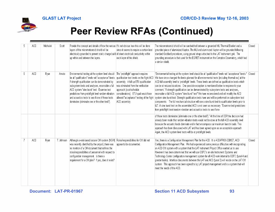
GLAST LAT Project CDR/CD-3 Review May 12-16, 2003
Document: LAT-PR-01967 Section 11 ACD Subsystem 93
Peer Review Peer Review RFAsRFAs (Continued) (Continued)
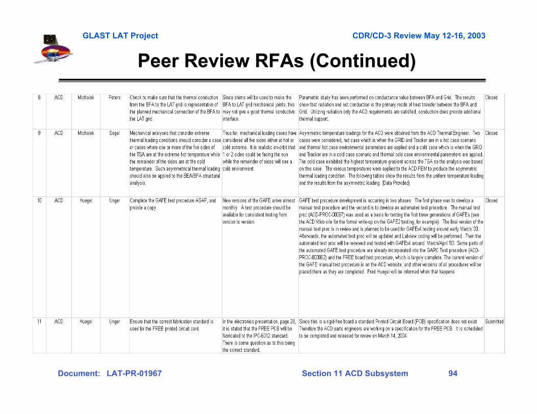
GLAST LAT Project CDR/CD-3 Review May 12-16, 2003
Document: LAT-PR-01967 Section 11 ACD Subsystem 94
Peer Review Peer Review RFAsRFAs (Continued) (Continued)

GLAST LAT Project CDR/CD-3 Review May 12-16, 2003
Document: LAT-PR-01967 Section 11 ACD Subsystem 95
Peer Review Peer Review RFAsRFAs (Continued) (Continued)
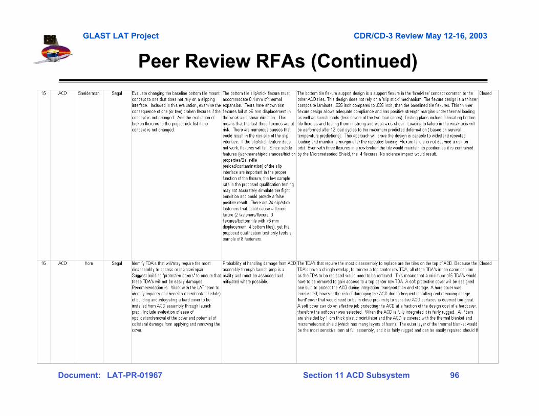
GLAST LAT Project CDR/CD-3 Review May 12-16, 2003
Document: LAT-PR-01967 Section 11 ACD Subsystem 96
Peer Review Peer Review RFAsRFAs (Continued) (Continued)
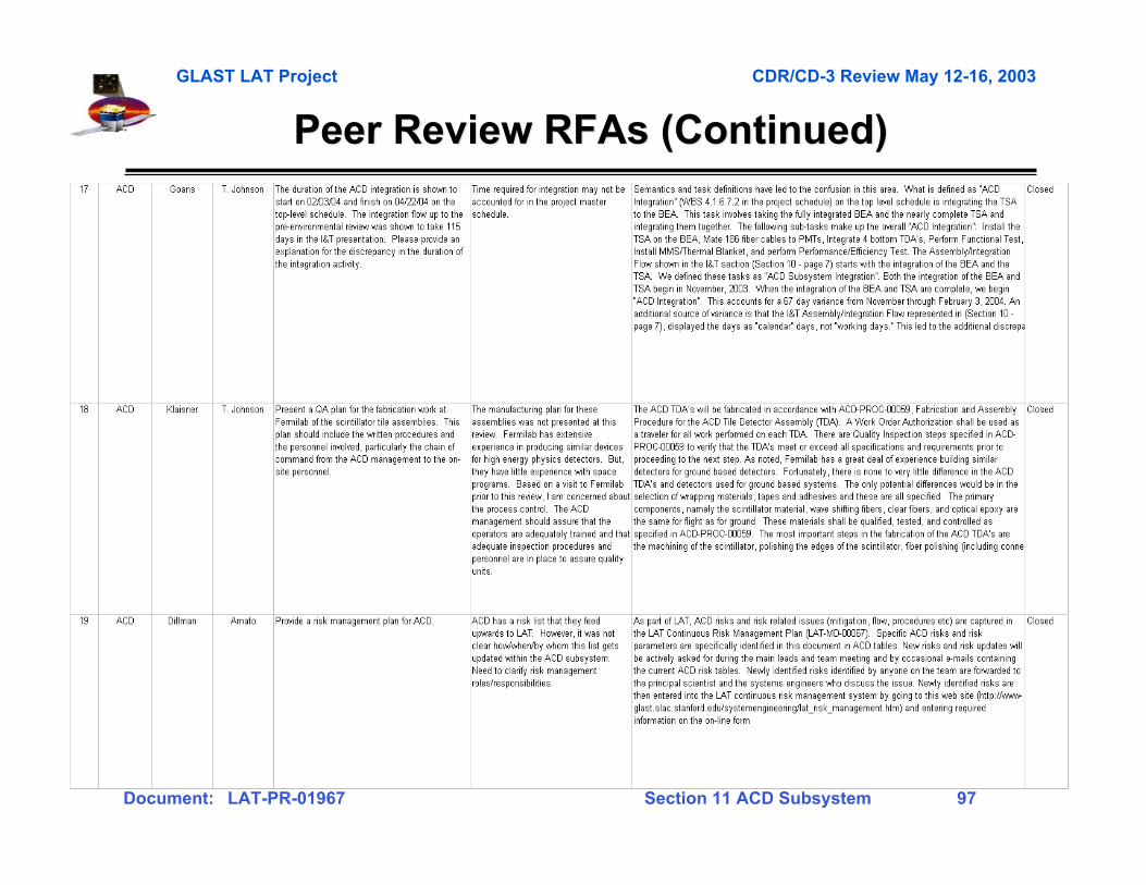
GLAST LAT Project CDR/CD-3 Review May 12-16, 2003
Document: LAT-PR-01967 Section 11 ACD Subsystem 97
Peer Review Peer Review RFAsRFAs (Continued) (Continued)