glast large area telescope: anticoincidence detector (acd) critical design review (cdr)
DESCRIPTION
Gamma-ray Large Area Space Telescope. GLAST Large Area Telescope: AntiCoincidence Detector (ACD) Critical Design Review (CDR) January 7 & 8, 2003. Agenda. DAY 1 – January 7 Section 1 - ACD Overview8:30-9:15 Section 2 - ACD Management9:15-9:50 BREAK9:50-10:00 - PowerPoint PPT PresentationTRANSCRIPT

GLAST LAT Project ACD CDR January 7 & 8, 2003
Sections 1-2 Anticoincidnce Detector Overview and Management 1
GLAST Large Area Telescope:GLAST Large Area Telescope:
AntiCoincidence Detector (ACD)
Critical Design Review (CDR)
January 7 & 8, 2003
Gamma-ray Large Gamma-ray Large Area Space Area Space TelescopeTelescope

GLAST LAT Project ACD CDR January 7 & 8, 2003
Sections 1-2 Anticoincidnce Detector Overview and Management 2
DAY 1 – January 7
Section 1 - ACD Overview 8:30-9:15Section 2 - ACD Management 9:15-9:50BREAK 9:50-10:00Section 3 - Systems Engineering 10:00-11:00Section 4 – ACD Science 11:00-11:45LUNCH 11:45-12:45Section 5 - Mechanical 12:45-3:00BREAK 3:00-3:10Section 6 - Electrical 3:10-5:00
Agenda

GLAST LAT Project ACD CDR January 7 & 8, 2003
Sections 1-2 Anticoincidnce Detector Overview and Management 3
DAY 2 – January 8
Section 7 - MGSE 8:30-8:55Section 8 - EGSE, Perf. Mon., & Calib. 8:55-9:15Section 9 - Safety and Mission Assurance 9:15-10:00BREAK 10:00-10:15Section 10 - Integration and Test 10:15-11:00Summary 11:00-11:15Closeout 11:15-12:00
Agenda

GLAST LAT Project ACD CDR January 7 & 8, 2003
Sections 1-2 Anticoincidnce Detector Overview and Management 4
Review Board TeamReview Board Team
• Dennis Dillman/301 Review Chairman• James Ryan/543 Mechanical Engineering• Steve Scott/500 Chief Engineer• Gary Sneiderman/556 Instrument Management• Fred Huegel/560 Electrical Engineering• Joseph Bolek/532 Systems Engineering• Ted Michalek/545 Thermal Engineering• Mark Goans/301 Systems Review Office• Lowell Klaisner/SLAC LAT Chief Engineer• Dick Horn/SLAC LAT Systems Engineer

GLAST LAT Project ACD CDR January 7 & 8, 2003
Sections 1-2 Anticoincidnce Detector Overview and Management 5
GLAST Large Area Telescope:GLAST Large Area Telescope:
AntiCoincidence Detector (ACD)WBS 4.1.6Overview
David J. Thompson, Subsystem [email protected] (301) 286-8168
NASA Goddard Space Flight Center
Gamma-ray Large Gamma-ray Large Area Space Area Space TelescopeTelescope
GLAST LAT Project ACD CDR January 7 & 8, 2003
Sections 1-2 Anticoincidnce Detector Overview and Management 6
OutlineOutline
• Overview of LAT and ACD• Level III Requirements Summary• Meeting Key Requirements• Flowdown – Requirements to Design• Design Evolution• Optimization• Technical Heritage• Reviews – Past and Future• Summary of July ΔPDR• Status of January LAT PDR Recommendations

GLAST LAT Project ACD CDR January 7 & 8, 2003
Sections 1-2 Anticoincidnce Detector Overview and Management 7
e+ e–
Overview of LATOverview of LAT
• Precision Si-strip Tracker (TKR) Precision Si-strip Tracker (TKR) 18 XY tracking planes. Single-sided silicon strip detectors (228 m pitch) Measure the photon direction; gamma ID.
• Hodoscopic CsI Calorimeter(CAL)Hodoscopic CsI Calorimeter(CAL) Array of 1536 CsI(Tl) crystals in 8 layers. Measure the photon energy; image the shower.
• Segmented Anticoincidence Detector Segmented Anticoincidence Detector (ACD)(ACD) 89 plastic scintillator tiles. Reject background of charged cosmic rays; segmentation removes self-veto effects at high energy.
• Electronics System Electronics System Includes flexible, robust hardware trigger and software filters.
Systems work together to identify and measure the flux of cosmic gamma Systems work together to identify and measure the flux of cosmic gamma rays with energy 20 MeV - >300 GeV.rays with energy 20 MeV - >300 GeV.
Calorimeter
Tracker
ACD [surrounds 4x4 array of TKR towers]

GLAST LAT Project ACD CDR January 7 & 8, 2003
Sections 1-2 Anticoincidnce Detector Overview and Management 8
LAT Anticoincidence DetectorLAT Anticoincidence Detector• TILE SHELL ASSEMBLY
– 89 Plastic scintillator tiles– Waveshifting fiber light collection (with
clear fiber light guides for long runs)– Two sets of fibers interleaved for each tile– Tiles overlap in one dimension– 8 scintillating fiber ribbons cover gaps in
other dimension (not shown)– Supported on self-standing composite
shell– Covered by thermal blanket +
micrometeoroid shield (not shown)• BASE ELECTRONICS ASSEMBLY
– 194 photomultiplier tube sensors (2/tile)– 12 electronics boards (two sets of 6), each
handling up to 18 phototubes. Two High Voltage Bias Supplies on each board.
Base Electronics Assembly (BEA)
Tile Shell Assembly (TSA)
Prototype ACD tile read out with Wavelength Shifting Fiber

GLAST LAT Project ACD CDR January 7 & 8, 2003
Sections 1-2 Anticoincidnce Detector Overview and Management 9
ACD Tile Detector Assembly (TDA)ACD Tile Detector Assembly (TDA)
Scintillator tile/Waveshifting fibers Optical connector/Clear fibers Phototube/Resistor Network
Flight-design TDAs have been successfully built, performance–tested, mounted on a flight-like composite structure, and environmentally tested to qualification levels (vibration and thermal vacuum).

GLAST LAT Project ACD CDR January 7 & 8, 2003
Sections 1-2 Anticoincidnce Detector Overview and Management 10
Tracker
Calorimeter
Tracker
Calorimeter
Charged particles produce signals lined up in the
segmented ACD, TKR, CAL
A high-energy gamma ray can produce secondary photons that “splash” out of the CAL and can trigger an ACD tile.
If the ACD were not segmented, we would lose the valuable high-energy gamma rays that produced a back-splash signal. This self-veto reduced the EGRET efficiency at high energies by more than 50%.
Charged Particle Detection vs. Backsplash

GLAST LAT Project ACD CDR January 7 & 8, 2003
Sections 1-2 Anticoincidnce Detector Overview and Management 11
Level III Key Requirements SummaryLevel III Key Requirements Summary
Parameter Requirement Expected Performance Verification Method
Detection of Charged Particles
0.9997 average detection efficiency over entire area of ACD (less for bottom row of tiles)
0.9997 0.99 (bottom tiles)
Test and Analysis
Fast VETO signal Logic signal 200-1600 nsec after passage of charged particle
200-1600 nsec Demonstrate
PHA signal For each phototube, pulse height measurement for each Trigger Acknowledge (TACK) Below 10 MIP, precision of <0.02 MIP or 5% (whichever larger) Above 10 MIP, precision of < 1 MIP or 2% (whichever larger)
< 0.02 MIP or 5% < 1 MIP or 2%
Test and Analysis
False VETO rate - backsplash
< 20% false VETO's due to calorimeter backsplash at 300 GeV
< 20% Test and Analysis
False VETO rate - noise < 1% gamma-ray rejection from false VETO's due to electrical noise
< 1% Analysis
High Threshold (Heavy Nuclei) Detection
Detection of highly-ionized particles (C-N-O or heavier) for calorimeter calibration.
Yes Analysis
Size Outside: 1796 x1796 x 1050 mm 1806 x 1806 for lowest 310mm Inside Grid: 1574 x 1574 x 204.7 mm Inside TKR: 1515.5 x 1515.5 x 650 mm
1796 x1796 x 1045 1800 x 1800 at connector 1574 x 1574 x 204.7 1515.5 x 1515.5 x 650
Demonstrate
Mass < 280 kg 270 Demonstrate Power < 31 Watts (conditioned) 14 Demonstrate Instrument Lifetime Minimum 5 yrs > 5 yr. Analysis
Reference: LAT-SS-00016

GLAST LAT Project ACD CDR January 7 & 8, 2003
Sections 1-2 Anticoincidnce Detector Overview and Management 12
Meeting the Key RequirementsMeeting the Key Requirements
Charged Particles
(MIP)
Backsplash + noise
For high-efficiency MIP detection (0.9997), want a low energy threshold.
For good rejection of backsplash, want a high energy threshold.
A good balance between these requirements is about 0.3 of the MIP peak energy. Energy

GLAST LAT Project ACD CDR January 7 & 8, 2003
Sections 1-2 Anticoincidnce Detector Overview and Management 13
Flowdown - Requirements to DesignFlowdown - Requirements to DesignParameter Requirement Constraints Characteristics Needed Design Detection of Charged Particles
0.9997 average detection efficiency over entire area of ACD (less for bottom row of tiles)
Mass Power Size Lifetime Minimize inert material outside active detector Low backsplash sensitivity
High-sensitivity charged particle detector No gaps Low energy threshold for high efficiency Performance margin to compensate for aging
False VETO rate - backsplash
< 20% false VETO's due to calorimeter backsplash at 300 GeV
High charged particle detection efficiency Mass Power Size Lifetime
Detector with low sensitivity to soft photons Segmentation < 1000 cm2 High energy threshold (backsplash is soft)
Plastic scintillator tiles, 1 cm thick, < 1000 cm2 size Waveshifting fiber light collection, with clear fibers for transmission in long runs Overlap one dimension, seal other with scintillating fiber ribbons Photomultiplier tubes, with gain set low at start of mission to allow increase as tube ages. Low-noise electronics Threshold well below MIP peak but above most of backsplash
Note that each requirement is a constraint on the
other.
Note that each requirement is in tension with the
other.

GLAST LAT Project ACD CDR January 7 & 8, 2003
Sections 1-2 Anticoincidnce Detector Overview and Management 14
Evolution of the ACD DesignEvolution of the ACD DesignProposal Design
145 tiles, 290 phototubes each with HVBS
Stand-alone electronics (ASIC/FPGA/ADC)
Processed signals sent to LAT electronics
Little mechanical support for electronics
Current Design
89 tiles, 8 ribbons, 194 phototubes, redundant HVBS for each 18 phototubes
Front-end electronics (ASIC/ADC)
Little processing of signals sent to LAT electronics
Realistic mechanical support for electronics

GLAST LAT Project ACD CDR January 7 & 8, 2003
Sections 1-2 Anticoincidnce Detector Overview and Management 15
ACD Optimization - SummaryACD Optimization - Summary
• Light Collection - optimized with 5 mm fiber spacing, TETRATEC wrapping material, aluminized fiber ends, multiclad fibers. Scintillator manufacturer does not matter. Two sets of interleaved fibers for redundant readout.
• Absolute Efficiency - using the light collection described above, a single phototube meets the 0.9997 efficiency requirement at 0.3 MIP threshold if there are no appreciable light losses. Light losses in long waveshifting fibers or connector to clear fibers makes the single tube marginal. Fibers were re-routed to shorter paths. With two tubes operating, there is ample margin. The top center row of tiles was thickened to give more light.
• Broken Fibers - the ACD could meet its requirements with up to two broken fibers on all tiles.
• Segmentation - the 89-tile design meets the backsplash requirements. • Hermeticity - a triple layer of square 1.5 mm fibers with offset centers
provides adequate sealing of the gaps between tiles. Overlaps were increased to allow for vertical gaps required by acoustic loads.
• REFERENCE: LAT-TD-00438-D2

GLAST LAT Project ACD CDR January 7 & 8, 2003
Sections 1-2 Anticoincidnce Detector Overview and Management 16
ACD Technical HeritageACD Technical Heritage
• Plastic Scintillator - used in all previous gamma-ray telescopes OSO-3, SAS-2, COS-B, CGRO (all 4 instruments), plus many cosmic ray experiments.
• Waveshifting fibers - used in GLAST LAT Balloon Flight Engineering Model (BFEM). Waveshifting bars used by HEXTE on RXTE (same material in a different geometry)
• Photomultiplier tubes - used in all previous gamma-ray telescopes. HEXTE/RXTE used a commercial version of the same tube we are using (Hamamatsu 4443), and GOLF on SOHO used the same tube as the ACD except for the cathode material (Hamamatsu 4444)
• High Voltage Bias Supplies - used in all previous gamma-ray telescopes, plus many cosmic ray experiments.
• Electronics - similar ASIC’s (same designer) used on the BFEM. Discriminators, PHA and logic signals similar to many flight instruments.
• Micrometeoroid Shield - Improved version (more layers, stronger materials) of shield that protected EGRET successfully for nine years.

GLAST LAT Project ACD CDR January 7 & 8, 2003
Sections 1-2 Anticoincidnce Detector Overview and Management 17
Reviews – Past and FutureReviews – Past and Future• Past Reviews:
– LAT Internal Review of the ACD – January, 1999– Pre-PDR/Baseline Review – February, 2001– LAT System Requirement Review (SRR)- May 2001– ACD Peer Review – July, 2001
• 62 RFA’s – All closed out– LAT PDR/Baseline Review – January, 2002
• 12 RFA’s – All closed out– LAT Internal Stanford Linear Accelerator Center Review - April, 2002– LAT Delta PDR/Baseline Review - July, 2002
• 3 RFA’s – All closed out• Future Reviews:
– LAT Critical Design Review (CDR) - April 2003– ACD Pre-Environmental Review (PER) – March 2004– ACD Pre-Ship Review (PSR) – June 2004– LAT Pre-Environmental Review (PER) - February 2005– LAT Pre-ship Review (PSR) - July 2005

GLAST LAT Project ACD CDR January 7 & 8, 2003
Sections 1-2 Anticoincidnce Detector Overview and Management 18
Summary of July Delta-PDR ReviewSummary of July Delta-PDR Review
“Subsystem managers have done a very good job of getting the Anti-Coincidence Detector(ACD) ready for this review. All the recommendations from the January 2002 DOE/NASA review were addressed. In particular, a new bottoms-up Work Breakdown Structure was created, contingency and critical path analyses were performed, and Basis of Estimate was provided.
Technical progress has been made on three fronts:• R&D was continued to finalize layout of the scintillator tile geometry.• New data was collected during test-beam at CERN to measure
backsplash effect (self-veto of gamma events).• Full size mock-up of ACD was built at GSFC to work out details of
fiber routing.”

GLAST LAT Project ACD CDR January 7 & 8, 2003
Sections 1-2 Anticoincidnce Detector Overview and Management 19
Status of January Review RecommendationsStatus of January Review Recommendations
1. Finalize the design and generate the engineering drawings for the tile and fiber layout, including the lowest row of the ACD.
• Designs for the 12 types of tile have been analyzed for thermal and vibration tolerances. Results are being used to generate engineering drawings.• Design for the lowest tile row has been tested and shown to exceed the requirements. • Drawings have been made for the routing of the fibers from the tiles to the phototubes. The routing has been checked using a mock-up of the ACD
Prototype tile for the lowest row of the ACD. Testing shows that this design exceeds the 0.99 efficiency requirement.

GLAST LAT Project ACD CDR January 7 & 8, 2003
Sections 1-2 Anticoincidnce Detector Overview and Management 20
Status of January Review RecommendationsStatus of January Review Recommendations
2. Perform light yield tests and muon detection efficiency measurement of the final optical system (scintillator tiles; and fiber ribbons, connector, clear fibers, and photomultiplier tubes).
Complete – results are similar to those shown in January: with two phototubes, 0.9997 efficiency is met; with one phototube, efficiency is ~ 0.999
Light output of Fermilab tiles is good. Light losses in the optical connector and clear fibers were higher than expected. Design improvements were made to compensate for these losses.
LAT-TD-00843-D1, Design Qualification Tests for ACD TDA and Phototubes
Performance of a full end-to-end TDA

GLAST LAT Project ACD CDR January 7 & 8, 2003
Sections 1-2 Anticoincidnce Detector Overview and Management 21
Status of January Review RecommendationsStatus of January Review Recommendations
3. Demonstrate that electronic noise of the system is low enough not to affect the muon rejection efficiency and efficiency for gammas by more than one percent.
• Bench tests of the first analog ASICs show no noise problem. Tests on a prototype electronics set (GAFE2 + GARC1) show good separation between MIP and noise signals.• The ACD electronics noise is required to be < 0.2 X threshold. The early calculations show that the noise at the lowest threshold setting of 0.1 MIP is approximately 50% lower than the requirement.• The ACD team along with the LAT Electronics Systems Engineers have developed a grounding and shielding design to keep noise to a minimum.
PHA distribution from qualification phototube, resistor network, GAFE, GARC, and ADC.

GLAST LAT Project ACD CDR January 7 & 8, 2003
Sections 1-2 Anticoincidnce Detector Overview and Management 22
Status of January Review RecommendationsStatus of January Review Recommendations
4. Complete full mockup of ACD, including clear fiber layout to photomultiplier tubes.
The mockup has been built and fiber routing placements have been completed.
Full-scale mock-up of ACD being used for tile placement and fiber routing from tiles to phototubes. Two bottom tile rows have been included.
Details of mock-up.

GLAST LAT Project ACD CDR January 7 & 8, 2003
Sections 1-2 Anticoincidnce Detector Overview and Management 23
Status of January Review RecommendationsStatus of January Review Recommendations
5. Perform thermal cycle of fully assembled tiles and ribbons. Verify that no damage to tile/fiber assemblies takes place and light yield is not decreased.
• Thermal cycle was -65 C to +45 C.
• Performance was measured using a muon telescope for Minimum Ionizing Particles.
• After > 340 cycles, the loss of performance was less than 5%.
LAT-TD-00858-D1, ACD TDA Thermal Cycling Test
Light yield of Tile/fiber assembly during thermal cycling.

GLAST LAT Project ACD CDR January 7 & 8, 2003
Sections 1-2 Anticoincidnce Detector Overview and Management 24
Status of January Review RecommendationsStatus of January Review Recommendations
6. Prepare a plan for Quality Control (tile response uniformity and broken fibers) and initial calibration (ADC/minimum ionizing particle) of the ACD system prior to the delivery to the Stanford Linear Accelerator Center.• Quality Control is covered by the general ACD Quality Plan (ACD-QA-
8001). • The methods for determining tile response uniformity and detecting
broken fibers are documented in “Light Collection/Optical Performance Tests” (LAT-TD-00438-D2). Performance is measured using a muon telescope for Minimum Ionizing Particles.
• A plan for calibrating the ACD using a muon telescope for mapping reference efficiency and then using internal triggers for PHA distributions is described in “ACD Gain Calibration Test with Cosmic Ray Muons” (LAT-TD-00844-D1). This approach was tested using the balloon flight ACD.
• Quality plans and acceptance tests for the Tile Detector Assemblies and phototubes have been developed: “ACD Phototube Quality Plan and Acceptance Tests” (LAT-TD-1202), “ACD Tile Detector Assembly Quality Plan and Acceptance Tests” (LAT-TD-1203).

GLAST LAT Project ACD CDR January 7 & 8, 2003
Sections 1-2 Anticoincidnce Detector Overview and Management 25
Status of January Review RecommendationsStatus of January Review Recommendations
7. Additional time should be added to the ASIC production schedule to provide some schedule margin.– The current LAT extended schedule incorporates an additional
month for ASIC development and additional testing time.– The GSFC Program management approved qualification and
screening process for the ASICs is now shorter than the original one.
– The analog ASIC remains a critical path in the schedule.
PAD FRAME OFTANNER I/O CELLS
LVDS CELLS
LOGIC CORE
VDD RAIL GND RAIL
SIGNALROUTINGTO PAD FRAME
GARC Layout GAFE Veto Generation – 1 MIP

GLAST LAT Project ACD CDR January 7 & 8, 2003
Sections 1-2 Anticoincidnce Detector Overview and Management 26
Status of January Review RecommendationsStatus of January Review Recommendations
8. Complete the bottoms-up Work Breakdown Structure (WBS) in the Primavera framework. This include a WBS Dictionary and full Basis of Estimate. More than 800 activities in our resource loaded schedule.– The WBS has been completed and has 10 major elements:– 4.1.6.1 Project Management/Systems Engineering/Science – 4.1.6.2 Safety and Mission Assurance– 4.1.6.3 Tile Shell Assembly– 4.1.6.4 Base Electronics Assembly– 4.1.6.5 Micrometeoroid Shield/Thermal Blanket Assembly– 4.1.6.6 Mechanical Qualification and Calibration Unit– 4.1.6.7 Integration and Test – 4.1.6.8 LAT Integration and Test Support– 4.1.6.9 Mission Integration and Test Support– 4.1.6.B Ground Support Equipment and Facilities

GLAST LAT Project ACD CDR January 7 & 8, 2003
Sections 1-2 Anticoincidnce Detector Overview and Management 27
Status of January Review RecommendationsStatus of January Review Recommendations9. Perform the critical path schedule analysis for the entire
subsystem. Provide detailed documentation (at the lowest level of WBS) for the Basis of Estimate of the costs, in particular the on-project and off-project labor costs.
Two critical paths have been identified (details in a later slide):• ASIC development and testing. Four iterations of the analog
ASIC is scheduled. Turnaround time from submittal to delivery is typically at least 12 weeks. Adding testing time means that one iteration can take at least four months. Shortened time for the screening testing helps. Scheduled ACD delivery is 9 weeks before the LAT integration need date.
• Photomultiplier tube delivery and assembly. The 6-month schedule extension alleviated that pressure somewhat, but the need to have a full set of tubes before assembly still makes this schedule fairly tight.
A detailed Basis of Estimate is available. Summaries in later slides.

GLAST LAT Project ACD CDR January 7 & 8, 2003
Sections 1-2 Anticoincidnce Detector Overview and Management 28
Status of January Review RecommendationsStatus of January Review Recommendations
10. Perform the contingency analysis of the subsystem. In particular, assess contingency for the off-project labor tasks.
A detailed contingency analysis, including all aspects of the ACD, has been carried out and incorporated into the PMCS. Some examples of contingency are shown in later slides.

GLAST LAT Project ACD CDR January 7 & 8, 2003
Sections 1-2 Anticoincidnce Detector Overview and Management 29
Status of January Review RecommendationsStatus of January Review Recommendations
11. Due to lack of a verifiable Work Breakdown Structure (cost estimate) for the ACD, the subsystem is not ready to be baselined at the present time. Consider the following streamlining steps:– Separate materials and services from the labor tasks at lowest
WBS level– Identify all the off-project labor costs at the lowest WBS level– Use the actual, fully loaded costs for technicians, specialists,
engineers, etc., in all WBS labor estimates
• The PMCS contains this detailed information. Each resource is identified. Summaries are presented in later slides.
• Because the Goddard tax system is based on estimates rather than actuals, the labor costs are not fully loaded.
12. Conduct a Subsystem Baseline Review as soon as the work on the subsystem Work Breakdown Structure is completed.Review was successfully completed in July.

GLAST LAT Project ACD CDR January 7 & 8, 2003
Sections 1-2 Anticoincidnce Detector Overview and Management 30
Status of July Status of July ΔΔPDR Review RecommendationsPDR Review Recommendations
1. Develop detailed specifications for the readout fibers (light yield, attenuation length, batch-to-batch variations) prior to the bid process and purchase of materials.– Material specifications and acceptance requirements are included in
the contract with Fermilab, “Fabrication and Assembly Procedure for the Anticoincidence Detector (ACD) Tile Detector Assembly (TDA)”, ACD-PROC-000059. Performed light attenuation measurements on readout fibers from two different manufactures.
2. Ensure that the second generation of the analog ASIC, (to be delivered in August 2002) is well evaluated before third generation is sent off to production.• Testing showed problems with the second generation analog ASIC.
The third generation, GAFE3, is being tested now, and a fourth generation, GAFE4, is due back later this month.
3. Continue to develop calibration plan for ACD for the Integration and Testing phase.• We are continuing to refine the calibration plan, building on our
experience with laboratory testing. Example: ACD Functional Test Plans (Comprehensive Performance Test) LAT-TD-01112-D1

GLAST LAT Project ACD CDR January 7 & 8, 2003
Sections 1-2 Anticoincidnce Detector Overview and Management 31
GLAST Large Area Telescope:GLAST Large Area Telescope:
AntiCoincidence Detector (ACD)WBS 4.1.6Management
Thomas E. Johnson, ACD Instrument [email protected] (301) 286-1284
NASA Goddard Space Flight Center
Gamma-ray Large Gamma-ray Large Area Space Area Space TelescopeTelescope

GLAST LAT Project ACD CDR January 7 & 8, 2003
Sections 1-2 Anticoincidnce Detector Overview and Management 32
OutlineOutline
• ACD Team Leads• ACD Team Partners• Contingency• ACD Organization Chart• Work Flow• Testing Overview• Fabrication Plan• Schedule• Cost• Procurements• Configuration Management• Micrometeoroid Shield• Issues and Concerns• Summary

GLAST LAT Project ACD CDR January 7 & 8, 2003
Sections 1-2 Anticoincidnce Detector Overview and Management 33
ACD Team LeadsACD Team Leads
– Dave Thompson – Scientist, ACD Subsystem Manager– Bob Hartman – Scientist– Alex Moiseev – Scientist– Tom Johnson – Instrument Manager– Mike Amato – Systems Engineer– Ken Segal – Lead Mechanical Engineer– Glenn Unger – Lead Electrical Engineer– Jim La – Integration and Test– Carlton Peters – Thermal Engineer– Andy Eaker – Scheduler– Deanna Adamcyzk - Resources

GLAST LAT Project ACD CDR January 7 & 8, 2003
Sections 1-2 Anticoincidnce Detector Overview and Management 34
ACD Team PartnersACD Team Partners
– Micrometeoroid Shield – Johnson Space Center• NASA Center of Excellence for micrometeoroid protection• Eric Christiansen and Jeanne Crews
– Tile Detector Assemblies – FermiLab (Department of Energy)• Experts in fabrication of scintillator detectors• Phyllis Deering and Todd Nebal
– Scintillating Fiber Ribbons – Washington University, St. Louis• Leaders in scintillating fiber production• Professor Robert Binns
– ASICs - Stanford Linear Accelerator Center (SLAC)• Extensive experience in ASIC design• Gunther Haller, Oren Milgrome, Dietrich Freytag

GLAST LAT Project ACD CDR January 7 & 8, 2003
Sections 1-2 Anticoincidnce Detector Overview and Management 35
ContingencyContingency• All contingency (mass, power, cost) held at the LAT project level.
Change requests are required to account for variance.• ACD Change Requests SubmittedChange Request # Description StatusLAT-XR-770-011 Add Redundant HVBS ApprovedLAT-XR-01009-01 Additional funding for scheduler ApprovedLAT-XR-1200-01 Mass increase from 235 kg to 280 kg ApprovedLAT-XR-01011-01 Analog ASIC cost over run (>$500K) PendingLAT-XR-01119-02 CDR Date Change ApprovedLAT-XR-01192-01 2 Level 3 milestone date changes ApprovedLAT-XR-00557-1 Mass increase from 205 kg to 235 kg ApprovedLAT-XR-01161-01 Micrometeoroid Design & Test (if change
in requirements is approved)Approved
LAT-XR-01001-01 Re-phasing of MPS and Lab Taxes ApprovedLAT-XR-1000-01 FY01 Carryover charges not in PMCS ApprovedLAT-XR-00691-01 New Baseline – April 2002 Approved

GLAST LAT Project ACD CDR January 7 & 8, 2003
Sections 1-2 Anticoincidnce Detector Overview and Management 36
ACD Organization ChartACD Organization Chart
ACD Systems Engineering4.1.6.1.2
Mike Amato, Lead
Tile Shell Assembly4.1.6.3
Ken Segal, Lead
Base Electronics Assembly
4.1.6.4Glenn Unger,
Lead
Micrometeoroid Shield /Thermal Blanket
4.1.6.5Tom Johnson, Lead
Carlton Peters, Thermal Lead
ACD Design and Science Support4.1.6.1.3
Alexander Moiseev,Lead
Tile Detector Assemblies
4.1.6.3.2A. Moiseev, Lead
ACD Reliability and Quality Assurance4.1.6.2
Patricia Huber, Lead
HardwareIntegration &
Test4.1.6.7
Jim La, Lead
Mission Integration
& Test Support4.1.6.9
Bob Hartman, Lead
Ground Support Facilities & Equipment
4.1.6.BJim La, Lead
LAT Instrument Integration &
TestSupport 4.1.6.8
Jim La, Lead
ACD management4.1.6.1
Tom Johnson, ManagerDeanna Adamczyk - Financial
ResourcesAndy Eaker - Scheduling
ACD Subsystem4.1.6
Dave Thompson, Subsystem Manager

GLAST LAT Project ACD CDR January 7 & 8, 2003
Sections 1-2 Anticoincidnce Detector Overview and Management 37
Tile Detector Assemblies 11/03
Shell 07/03 Subassembly
ASIC 10/03 Development
High Voltage Bias Supply 11/03
Photomultiplier tubes 11/03
Front End Electronics Card Assembly 11/03
Base Frame 07/03 Subassembly
Base Electronics Assembly 03/04
ACD Integration 03/04
Tile Shell Assembly 12/03
ACD Performance and Environmental Test 07/04
Thermal Blanket Micrometeoroid Shield 01/04
Completion Dates Shown
ACD Work Flow Overview
Ship 08/04
Tile Shell Assembly (TSA)
Base Electronics Assembly (BEA)
Electronics Chassis 02/04

GLAST LAT Project ACD CDR January 7 & 8, 2003
Sections 1-2 Anticoincidnce Detector Overview and Management 38
ACD Testing OverviewACD Testing Overview
• Due to size and cost, there is no full-size ACD Engineering Model. The full-size mechanical mockup is used only for fit checks and fabrication of the micrometeoroid shield/thermal blankets.
• Acceptance and Qualification tests, including performance, vibration, EMI/EMC, and thermal vacuum, are carried out at the component and subassembly level. Extrapolation to the full ACD is done by analysis.
• The full protoflight ACD will undergo a complete suite of tests, including absolute efficiency measurement as well as all environmental tests.
Subassembly vibration testing – a section of support shell, composite flexures supporting a scintillator tile, and a micrometeoroid shield/thermal blanket. A similar test included the waveshifting fibers, optical connector, optical fibers, and phototubes.

GLAST LAT Project ACD CDR January 7 & 8, 2003
Sections 1-2 Anticoincidnce Detector Overview and Management 39
Development Testing OverviewDevelopment Testing Overview
Thermal Vacuum testing – a section of support shell with composite flexures, three Tile Detector Assemblies, and four PMT/RN assemblies were exposed to 6 thermal vacuum cycles. ACD-PROC-000068, TDA-PMT-Resistor Network End-to-End Thermal-Vacuum Test Procedure
Vibration testing – a section of support shell, composite flexures supporting a scintillator tile, and a micrometeoroid shield/thermal blanket. A similar test included the waveshifting fibers, optical connector, and optical fibers. ACD-PLAN-000032, LAT-ACD Tile Detector Test Vibration Test Plan
Vibration testing – 4 PMT/RN assemblies with clear fibers connected to 3 TDA’s (not vibrated) were subjected to vibration testing.

GLAST LAT Project ACD CDR January 7 & 8, 2003
Sections 1-2 Anticoincidnce Detector Overview and Management 40
ACD Fabrication PlanACD Fabrication Plan
• Tile Detector Assemblies– Fermi Lab
• Composite Shell– Panel fabrication performed by outside vender, assembly and test in house
• Base Frame– In house fabrication, assembly and test
• Analog and Digital ASIC’s– GSFC/SLAC Design, MOSIS fabrication, GSFC acceptance testing
• High Voltage Bias Supplies– In house design, fabrication by local vender, testing in house
• PMT/Resistor Network Assembly– Procure components and assemble and test in house
• Front End Electronic (FREE) Boards– Procure components and assemble and test in house
• Micrometeoroid Shield/Thermal Blanket– Shield designed by JSC, Blanket designed by GSFC, In house fabrication
• ACD Integration and Test– Building 7, 10, 15, & 29 complex
Qualification phototube in housing with resistor network.

GLAST LAT Project ACD CDR January 7 & 8, 2003
Sections 1-2 Anticoincidnce Detector Overview and Management 41
Top-Level ScheduleTop-Level Schedule

GLAST LAT Project ACD CDR January 7 & 8, 2003
Sections 1-2 Anticoincidnce Detector Overview and Management 42
1rst Critical Path - Analog ASIC1rst Critical Path - Analog ASICActivity Dates3rd-5th Generation Analog ASIC Design 8/22/02-2/13/03
Flight Unit (FU) Analog ASIC submitted to fabrication 2/14/03
FU Analog ASIC Development (fab, package, test, screen) 2/14/03-10/08/03
FREE FU Populate w/Analog ASIC,Digital ASIC, ADC, & DAC 10/17/03-11/13/03
Electronics Chassis FU Pop w/PMT’s & Inspect 11/14/03-12/01/03
Electronics Chassis FU Validation Testing 12/3/03-2/2/04
BEA Integration (4 installments) 2/3/04-3/2/04
Install TSA on BEA 3/3/04-3/9/04
Mate & Test Fiber Cables to PMT’s 3/10/04-3/16/04
Mate, Install, & Test 4 Lower TDA’s 3/17/04-3/18/04
ACD Functional and Performance Testing 3/19/04-4/22/04
ACD Environmental Tests 4/23/04-7/21/04
Shipping to SLAC 7/22/04-8/6/04
Post Ship activities 8/7/04-8/25/04
Schedule Contingency 8/26/04-10/24/04
ACD to LAT Integration 10/25/04

GLAST LAT Project ACD CDR January 7 & 8, 2003
Sections 1-2 Anticoincidnce Detector Overview and Management 43
2nd Critical Path – PMT/Resistor Networks2nd Critical Path – PMT/Resistor NetworksActivity DatesPMT Procurement (90 of 240 flight units already received) 10/15/02-6/15/03
Resistor Network procurement, populate, assembly, & test 2/11/03-10/23/03
PMT Integrate and Test with Resistor Network 5/13/03-11/06/03
FREE FU Populate w/Analog ASIC,Digital ASIC, ADC, & DAC 10/17/03-11/13/03
Electronics Chassis FU Pop w/PMT’s & Inspect 11/14/03-12/01/03
Electronics Chassis FU Validation Testing 12/3/03-2/2/04
BEA Integration (4 installments) 2/3/04-3/2/04
Install TSA on BEA 3/3/04-3/9/04
Mate & Test Fiber Cables to PMT’s 3/10/04-3/16/04
Mate, Install, & Test 4 Lower TDA’s 3/17/04-3/18/04
ACD Functional and Performance Testing 3/19/04-4/22/04
ACD Environmental Tests 4/23/04-7/21/04
Shipping to SLAC 7/22/04-8/6/04
Post Ship activities 8/7/04-8/25/04
Schedule Contingency 8/26/04-10/24/04
ACD to LAT Integration 10/25/04
GLAST LAT Project ACD CDR January 7 & 8, 2003
Sections 1-2 Anticoincidnce Detector Overview and Management 44
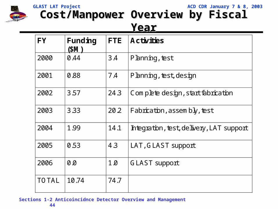
Cost/Manpower Overview by Fiscal YearCost/Manpower Overview by Fiscal YearFY Funding
($M) FTE Activities
2000 0.44 3.4 Planning, test
2001 0.88 7.4 Planning, test, design
2002 3.57 24.3 Complete design, start fabrication
2003 3.33 20.2 Fabrication, assembly, test
2004 1.99 14.1 Integration, test, delivery, LAT support
2005 0.53 4.3 LAT, GLAST support
2006 0.0 1.0 GLAST support
TOTAL 10.74 74.7

GLAST LAT Project ACD CDR January 7 & 8, 2003
Sections 1-2 Anticoincidnce Detector Overview and Management 45
ACD Cost ProfileACD Cost Profile
4.1.6 Anticoincidence DetectorCost Type
0.0
0.5
1.0
1.5
2.0
. . . . . . . . . . . . . . . . . . . . . . . .
FY00 FY01 FY02 FY03 FY04 FY05 FY06
$M, T
hen
Year
Dol
lars
Labor M & S ( no Travel ) Taxes (GSFC) Travel

GLAST LAT Project ACD CDR January 7 & 8, 2003
Sections 1-2 Anticoincidnce Detector Overview and Management 46
ProcurementsProcurements
• Long lead procurement– Photomultiplier Tubes – Have received 90 flight tubes
• Major upcoming procurements– Support Shell– Tile Detector Assemblies (with fibers)– Base Frame– Flight ASICs– High Voltage Bias Supplies– PMT Assembly
• Smaller upcoming procurements– Electrical components– Tile Detector Assembly mounts
Tile Detector Assembly withA clear fiber connector

GLAST LAT Project ACD CDR January 7 & 8, 2003
Sections 1-2 Anticoincidnce Detector Overview and Management 47
Configuration Management & Configuration Management & Information TechnologyInformation Technology
• GSFC CM System– Next Generation Integrated Network – Secure Web based configuration
management system. It is a full service CM system with the following services:
• Release and electronically store drawings, procedures, documents, and Work Order Authorizations (WOA’s)
• Action Item Database• Document Library
• LAT CM System– Cyberdocs – Web based document storage.
• ACD documents that involve the LAT (i.e. all interface and top level documents) will be placed on Cyberdocs
• Lower level ACD Documents, Drawings, and WOA’s will be on the GSFC CM System
• ACD Website: http://lhea-glast.gsfc.nasa.gov/acd/– Website is used to share information and store draft documents – Used
extensively prior to getting the CM system on-line

GLAST LAT Project ACD CDR January 7 & 8, 2003
Sections 1-2 Anticoincidnce Detector Overview and Management 48
Micrometeoroid Shield DesignMicrometeoroid Shield Design
3.27cmmax
(1) Nextel AF10
(1) Nextel AF10
(1) Nextel AF10
(6) Kevlar KM2
ComponentNumber
in Shield
Thickness each (cm)
Mass per Unit Area
each (g/cm2)
Total thickness
(cm)
Total Mass per Unit Area
(g/cm2)
Nextel AF10 4 0.0254 0.025 0.102 0.100
Solimide Foam Spacer
4 0.66 0.0051 2.640 0.020
Thermal Blanket
1 0.32 0.0368 0.320 0.037
Kevlar KM2 6 0.0254 0.023 0.152 0.138
Overall Shield 3.21 0.295
• Purpose: To prevent light leaks in Tile Detector Assemblies due to micrometeoroid penetrations
• Analysis and Testing being performed by Johnson Space Center (Eric Christianson & Jeanne Crews)
• LAT-TD-1122.1 – “ACD Micrometeoroid Shield Analysis and Design”• Current Design based on ORDEM96:
(1) Nextel AF10

GLAST LAT Project ACD CDR January 7 & 8, 2003
Sections 1-2 Anticoincidnce Detector Overview and Management 49
Micrometeoroid Shield RequirementsMicrometeoroid Shield Requirements
Parameter Requirement Expected Performance
Compliance
Probability of No Penetration (PNP) over 5 years
95% PNP ORDEM96: 96.6% PNPORDEM2000:86.1% PNP
Y: analysis & testN: analysis & test
Thickness <3.27 cm ORDEM96:3.21 cmORDEM2000:<3.27
Y: analysis & testingTBD
Areal density <0.32 g/cm2 ORDEM96: 0.295 g/cm2
ORDEM2000:<0.32 g/cm2
Y: analysis & testTBD
• Requirements are being updated. ORDEM2000 is replacing ORDEM96

GLAST LAT Project ACD CDR January 7 & 8, 2003
Sections 1-2 Anticoincidnce Detector Overview and Management 50
Micrometeoroid Shield TestingMicrometeoroid Shield Testing
• To measure the difference between models, we took a thermal blanket and wrapped tile with a phototube to Houston (Rice University), combined it with a flight-design shield, and tested it using high-velocity particles at their test facility.
• Testing particles and shields of several sizes, we determined that the existing shield design needs to be improved to enable the Micrometeoroid Shield to achieve its required 95% PNP over 5 years.
• Re-design has been approved (estimate ~$25K). Waiting on final requirements flowdown from GLAST and LAT before proceeding. Light gas gun, operated by JSC at Rice University.
We tested ~2 mm Al particles at 7 km/s.
Damage to the interior part of the shield from a 2.2 mm particle. The hole is about 30 mm diameter. The Kevlar backing sheets stopped the debris (this time).

GLAST LAT Project ACD CDR January 7 & 8, 2003
Sections 1-2 Anticoincidnce Detector Overview and Management 51
ACD Issues/ConcernsACD Issues/Concerns• The schedule is tight. The ACD critical path (analog ASIC) has
little room for delay. We are drawing on SLAC ASIC experience to minimize risk.
• There is no ACD Engineering Model. Although testing will be done on components and subassemblies, the first full-scale test will be on the flight unit.
• The ACD is not completely redundant. Loss of a tile, a phototube, or an electronics channel would reduce the ACD efficiency, although risk assessment shows not enough loss to have a significant impact on science.
• The ACD is dependent on Goddard Civil Service manpower and test facilities. We have a commitment from Goddard management and fairly high visibility, but crises in other programs have been known to pull manpower away and tie up facilities.

GLAST LAT Project ACD CDR January 7 & 8, 2003
Sections 1-2 Anticoincidnce Detector Overview and Management 52
SummarySummary
• The ACD continues to make technical progress. All the technical recommendations from the January and July reviews have been resolved.
• The ACD has developed a coherent, verifiable cost and schedule plan. Basis of Estimate, critical path analysis and contingency have been clarified.
• The schedule has two months of float at the end. • The ACD faces no unusual risks. The risks are those
experienced by any space flight instrument.• The ACD has an experienced team.• The ACD is ready to proceed with flight hardware fabrication.