gas measurement instruments ltd - sedasl.es · i copyright copyright this user handbook is...
TRANSCRIPT

Q 09760
Gas Measurement Instruments Ltd
User Handbook

Issue a (draft)
09/06/2011
Part Number: 64171
GMI welcomes comments on all our publications. Your comments can be of great value in helping us to improve our customer publications. Please send any comments that you have to our Sales Department at GMI. Contact details are provided inside the back cover of this handbook.
Instrument Service / Repair contact details are also provided inside the back cover of this handbook.
Copyright © Gas Measurement Instruments Ltd 2011
i
COPYRIGHT
COPYRIGHT
This User Handbook is copyright of Gas Measurement Instruments Ltd (GMI) and the information contained within is for use only with the GMI PS200 series instruments. Reproduction, in whole or in part, including utilisation in machines capable of reproduction or retrieval without written permission of Gas Measurement Instruments Ltd. is prohibited. Reverse engineering is not permitted.
LIABILITY
Every care has been taken in the preparation of this Handbook, but GMI Ltd. do not accept any responsibility for errors or omissions and their consequences. Information in this Handbook is subject to change without notice. This Handbook does not constitute a specification or basis for a contract. Your statutory rights under law are not affected.
MODIFICATION NOTICES
GMI aim to notify customers of relevant changes in the product operation and maintain this Handbook up to date. In view of the policy of continuous product improvement there may be operational differences between the latest product and this Handbook.
This Handbook is an important part of the PS200 product. Please note the following points:
• It should be kept with the instrument for the life of the product • Amendments should be attached to this Handbook • This Handbook should be passed on to any subsequent owner / user of
the instrument • Although every care is taken in the preparation of this Handbook, it does
not constitute a specification for the instrument.
SOFTWARE
Software supplied on microcontroller or similar device for use in a particular product, may only be used in that product and may not be copied without the written permission of Gas Measurement Instruments Ltd. Reproduction or disassembly of such embodied programmes or algorithms is prohibited. Ownership of such software is not transferable and Gas Measurement Instruments Ltd. does not warrant that the operation of the software will be error free or that the software will meet the customer’s requirements.
DISPOSAL ADVICE
When no longer in use, dispose of the instrument carefully and with respect for the environment. Refer to WEEE directive statement, such as:
ii
USER HANDBOOK
In compliance with the WEEE directive, GMI will dispose of the instrument without charge if the instrument is returned to GMI.
SAFETY
• The instrument must be regularly serviced and calibrated by fully trained personnel in a safe area thus user adjustment is not required.
• Replacement or charging of the equipment is only permitted in a non- hazardous area.
• Only GMI replacement parts should be used. • Instrument must be re-charged in a safe area before use. Refer to
Chapter 6 : ‘RECHARGE BATTERY’. • If the instrument detects gas, follow your own organisation’s procedures
and operational guidelines. • Gas can be dangerous and care should always be taken in its use. • This equipment is designed and manufactured to protect against other
hazards as defined in ATEX Directive 94/9/EC and UL913 (7th Edition). Any right of claim relating to product liability or consequential damage to any third party against GMI is removed if the above warnings are not observed.
AREAS OF USE
Exposure to certain chemicals can result in a loss of sensitivity of the flammable sensor. Where such environments are known or suspected it is recommended that more frequent response checks are carried out. (Refer to Chapter 3: ‘MANUAL BUMP TEST’). Chemical compounds that can cause loss of sensitivity include Silicones, Lead, Halogens and Sulphur.
Do not use instrument in potentially hazardous atmospheres containing greater than 21% Oxygen.
SPECIAL CONDITIONS OF USE
No precautions against electrostatic discharge are necessary for portable equipment that has an enclosure made of plastic, metal or a combination of the two, except where a significant static generating mechanism has been identified. Activities such as placing the item in a pocket or on a belt, operating a keypad or cleaning with a damp cloth, do not present a significant electrostatic risk. However, where a static-generating mechanism is identified, such as repeated brushing against clothing, then suitable precautions shall be taken, e.g. the use of anti-static footwear.
STORAGE, HANDLING AND TRANSIT
The instrument is designed to handle harsh environments. The instrument is sealed to IP67 and, if not subjected to misuse or malicious damage, will provide many years of reliable service.
iii
COPYRIGHT
The instrument can contain electrochemical sensors. Under conditions of prolonged storage these sensors should be removed. The sensor contains potentially corrosive liquid and care should be taken when handling or disposing of the sensor, particularly when a leak is suspected.
WARRANTY
The GMI PS200 instrument has a warranty against faulty goods or workmanship of 2 years. Consumable and Mechanical parts, e.g. pump, sensors, filters, etc., are not included in this. These are covered under GMI standard warranty conditions. For details, please contact GMI Ltd (UK).

iv
USER HANDBOOK
v
RECORD OF REVISIONS
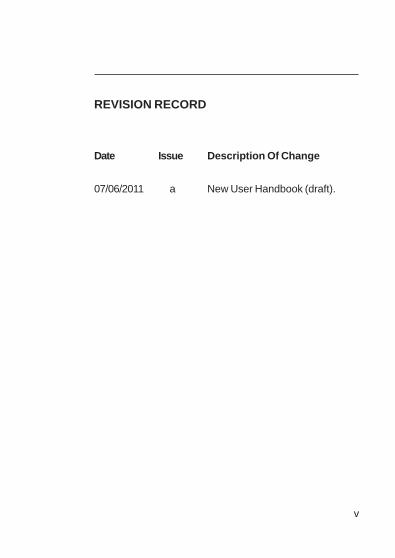
REVISION RECORD
Date Issue Description Of Change
07/06/2011 a New User Handbook (draft).

vi
USER HANDBOOK

vii
CONTENTS
TABLE OF CONTENTS
COPYRIGHT i
LIABILITY i
MODIFICATION NOTICES i
SOFTWARE i
DISPOSAL ADVICE i
SAFETY ii
AREAS OF USE ii
i
i
SPECIAL CONDITIONS OF USE i
STORAGE, HANDLING AND TRANSIT i
WARRANTY iii
REVISION RECORD v
INTRODUCTION 1-1

viii
USER HANDBOOK
1.1 GENERAL DESCRIPTION 1-1
1.2 FEATURES 1-4
1.3 DATA LOGGING 1-5 1.3.1 Archiving Stored Readings 1-6
1.4 FILTERS 1-6
1.5 CONSTRUCTION 1-6
1.6 IDENTIFICATION LABEL 1-7
1.7 PHYSICAL PROPERTIES 1-7 1.7.1 Environment 1-7
1.8 CERTIFICATION 1-8 1.8.1 Certification Marks 1-8
1.8.2 Performance 1-8
OPERATION 2-1
2.1 OPERATING PROCEDURE 2-1
2.2 SWITCH THE INSTRUMENT ON 2-2 2.2.1 Instrument Identification 2-3
2.2.2 Battery Status 2-4
2.2.3 User Name / Number Only (Option) 2-4
2.2.4 Man Down Alarm (Motion Sensor) Option 2-4
2.2.5 Date and Time 2-5
2.2.6 Calibration Due Date 2-6

ix
CONTENTS
2.2.7 Select Calibration Gas 2-7
2.2.8 Sensor Confirmation Check 2-8
2.2.9 Normal Operating Display 2-10
2.3 SWITCH THE DISPLAY BACKLIGHT ON / OFF 2-11
2.4 VIEW MAXIMUM AND MINIMUM RECORDED VALUES SINCE SWITCH ON 2-11
2.5 ALARMS RESET OR ACKNOWLEDGE 2-13 2.5.1 Confidence Signal 2-14
2.6 REMOTE SAMPLING (with pump option) 2-14 2.6.1 Pump Operation: 2-15
2.7 SELF TEST 2-15
2.8 SWITCH THE INSTRUMENT OFF 2-16
MANUAL BUMP TEST 3-1
3.1 BACKGROUND 3-1
3.2 MANUAL BUMP OPTIONS 3-2
3.3 INITIATING A MANUAL BUMP TEST 3-2
3.4 APPLYING TEST GAS 3-3
3.5 QUICK / FULL BUMP TEST 3-3 3.5.1 Quick Bump Test 3-4
3.5.2 Full Bump Test 3-4
x
USER HANDBOOK
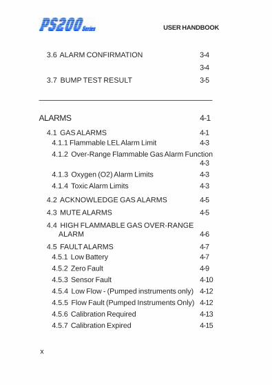
3.6 ALARM CONFIRMATION 3-4
3-4
3.7 BUMP TEST RESULT 3-5
ALARMS 4-1
4.1 GAS ALARMS 4-1 4.1.1 Flammable LEL Alarm Limit 4-3
4.1.2 Over-Range Flammable Gas Alarm Function 4-3
4.1.3 Oxygen (O2) Alarm Limits 4-3
4.1.4 Toxic Alarm Limits 4-3
4.2 ACKNOWLEDGE GAS ALARMS 4-5
4.3 MUTE ALARMS 4-5
4.4 HIGH FLAMMABLE GAS OVER-RANGE ALARM 4-6
4.5 FAULT ALARMS 4-7 4.5.1 Low Battery 4-7
4.5.2 Zero Fault 4-9
4.5.3 Sensor Fault 4-10
4.5.4 Low Flow - (Pumped instruments only) 4-12
4.5.5 Flow Fault (Pumped Instruments Only) 4-12
4.5.6 Calibration Required 4-13
4.5.7 Calibration Expired 4-15
xi
CONTENTS
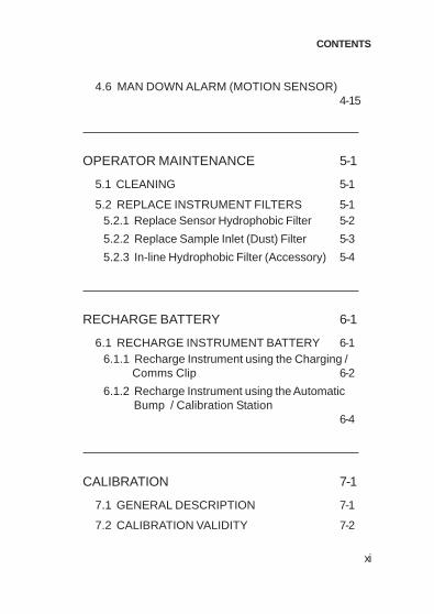
4.6 MAN DOWN ALARM (MOTION SENSOR) 4-15
OPERATOR MAINTENANCE 5-1
5.1 CLEANING 5-1
5.2 REPLACE INSTRUMENT FILTERS 5-1 5.2.1 Replace Sensor Hydrophobic Filter 5-2
5.2.2 Replace Sample Inlet (Dust) Filter 5-3
5.2.3 In-line Hydrophobic Filter (Accessory) 5-4
RECHARGE BATTERY 6-1
6.1 RECHARGE INSTRUMENT BATTERY 6-1 6.1.1 Recharge Instrument using the Charging / Comms Clip 6-2
6.1.2 Recharge Instrument using the Automatic Bump / Calibration Station
6-4
CALIBRATION 7-1
7.1 GENERAL DESCRIPTION 7-1
7.2 CALIBRATION VALIDITY 7-2

xii
USER HANDBOOK
ACCESSORIES 8-1
ADDITIONAL INFORMATION 9-1
9.1 TRAINING 9-1
9.2 WORLD WIDE WEB 9-1
INDEX i

1-1
INTRODUCTION
1
INTRODUCTION
1.1 GENERAL DESCRIPTION
The GMI PS200 series combines quality, ruggedness and advanced technology in a user friendly, portable gas detector. It is compact, lightweight, water resistant, extremely robust and is suitably certified to recognised International Standards.
The PS200 is designed for confined space monitoring, for example, in sewers, underground piping, or within tanks and other personal monitoring applications. With audible, visual and vibrating alarms, it provides early warning of dangerous gas levels.
The instrument is available as either a pumped or diffusion model and is powered by an internal Li-ion (lithium ion) rechargeable battery with minimum operating time of 14 hours for non-pumped operation (8 hours for pumped operation). Maximum recharge time is 4 hours.
Operated via two push buttons, this instrument provides the user with a simple to use, yet state-of-the-art, gas detector. (Fig. 1-1).
The PS200 series features high visibility LED’s, a display that changes colour from green to red when an alarm is present, a sounder with a 90dB minimum output and a vibrating alarm. Users can be confident that, should gas levels exceed configured threshold limits or a sensor / flow / battery fault exists, a clear and unmistakeable indication is evident.

1-2
USER HANDBOOK
Fig. 1-1 PS200 Series Instrument
The PS200 Series has the ability to detect up to 4 of the following gases simultaneously:
• 0 to 100% LEL Hydrocarbons
• 0 to 25% Oxygen (O2)
• 0 to 1000ppm Carbon Monoxide (CO)
• 0 to 100ppm Hydrogen Sulphide (H2S)
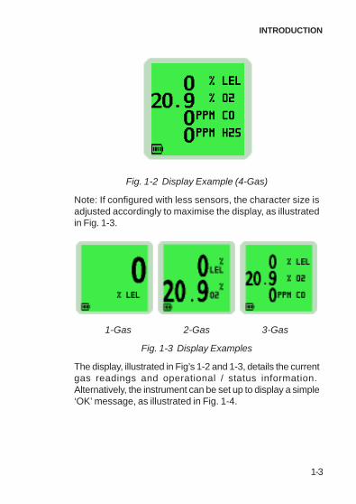
The instrument display identifies the gas(es) the instrument is monitoring. An example of a four gas instrument display is illustrated in Fig. 1-2:
1-3
INTRODUCTION
Fig. 1-2 Display Example (4-Gas)
Note: If configured with less sensors, the character size is adjusted accordingly to maximise the display, as illustrated in Fig. 1-3.
1-Gas 2-Gas 3-Gas
Fig. 1-3 Display Examples
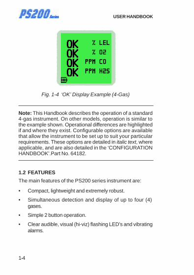
The display, illustrated in Fig’s 1-2 and 1-3, details the current gas readings and operational / status information. Alternatively, the instrument can be set up to display a simple ‘OK’ message, as illustrated in Fig. 1-4.
1-4
USER HANDBOOK
Fig. 1-4 ‘OK’ Display Example (4-Gas)
Note: This Handbook describes the operation of a standard 4-gas instrument. On other models, operation is similar to the example shown. Operational differences are highlighted if and where they exist. Configurable options are available that allow the instrument to be set up to suit your particular requirements. These options are detailed in italic text, where applicable, and are also detailed in the ‘CONFIGURATION HANDBOOK’.Part No. 64182.
1.2 FEATURES
The main features of the PS200 series instrument are:
• Compact, lightweight and extremely robust.
• Simultaneous detection and display of up to four (4) gases.
• Simple 2 button operation.
• Clear audible, visual (hi-viz) flashing LED’s and vibrating alarms.

1-5
INTRODUCTION
• Audible and visual confidence signal (fully configurable) every 15 seconds, confirming to the user that the instrument is correctly energised and operating normally.
• Motion sensor to detect movement and activate alarms in a ‘man down’ situation.
• Alphanumeric display with screen backlighting. Backlighting is coloured green during normal operation and red during alarm condition.
• Internal electric pump (optional) with a minimum flow rate of 0.5 litres per minute.
• Fully automatic data logging.
• Powered by an internal Li-Ion (Lithium Ion) rechargeable battery, this will provide an operating time of up to 14 hours (non-pumped) or 8 hours (pumped). Maximum recharge time is 4 hours.
• Robust crocodile clip to allow fitting to belt, pocket, etc.
• Communications interface to allow downloading of stored data.
• Fully certified to international standards.
• Comprehensive range of accessories available.
1.3 DATA LOGGING
Data logging is a standard feature of all PS200 series instruments and allows gas measurements, event logs, bump tests and calibration details to be automatically stored and later downloaded to a Personal Computer (PC) via a USB connection.
Manual data logging can also be achieved simply via a single
press of the Left Hand (LH) button .

1-6
USER HANDBOOK
The instrument can store in excess of 24 hours of readings at a recording interval of 1 minute, 180 On / Off event logs and alarms, 180 bump test logs and 8 calibrations.
1.3.1 Archiving Stored Readings
Stored readings can be downloaded from the PS200 series instrument to a PC, using the standard charging / comms cable and additional software. Contact the GMI Sales Department for further details.
1.4 FILTERS
The instrument is protected from water and dust ingress by hydrophobic and dust (sample inlet) filters.
These filters should be checked regularly and replaced if necessary (refer to ‘FILTER REPLACEMENT’ section in Chapter 5 ‘OPERATOR MAINTENANCE’).
1.5 CONSTRUCTION
The PS200 series is housed in a tough, impact resistant moulded case. Sealed to IP67, it can withstand physical impact testing to EN 61779.
1-7
INTRODUCTION
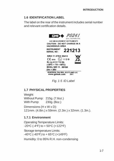
1.6 IDENTIFICATION LABEL
The label on the rear of the instrument includes serial number and relevant certification details.
Fig. 1-5 ID Label
1.7 PHYSICAL PROPERTIES
Weight: Without Pump: 215g. (7.6oz.) With Pump: 230g. (8oz.)
Dimensions (H x W x D): 121mm. (4.8in.) x 59mm. (2.3in.) x 32mm. (1.3in.).
1.7.1 Environment
Operating Temperature Limits: -20oC (-4oF) to + 50oC (+122oF)
Storage temperature Limits: -40oC (-40oF) to + 65oC (+149oF)
Humidity: 0 to 95% R.H. non-condensing

1-8
USER HANDBOOK
1.8 CERTIFICATION
The PS200 series instrument is certified as follows: Note: Check instrument labels for actual certification.
ATEX II 2 G EEx ia d IIC T4 Gb (Ta = -20oC to + 50oC)
IECEx EEx ia d IIC T4 Gb (Ta = -20oC to + 50oC)
UL 913 (7th. Edition) Class I Div.1 Groups A, B, C and D - Pending
Class I Div.1 Groups A, B, C and D - Pending
MED (Marine Equipment Directive) - A.1 / 3.30 - Pending
European Mark of Conformity
1.8.1 Certification Marks
Refer to the following for details:
www.europe.eu.atex
www.iecex.com
1.8.2 Perforformance
Complies with: EN 60079 (Flammable)
IEC 60079 (Flammable)
EN 50104 (Oxygen)
2-1
OPERATION
2
OPERATION
2.1 OPERATING PROCEDURE
Check the following:
• The PS200 instrument is clean and in good condition.
• The internal battery is fully charged.
• The hydrophobic and inlet filters are clean and in good condition.
• The sample line (pumped instruments) and any other accessories used are in good condition and leak-free.
• All gas ranges are operational and the instrument is zeroed.
• The instrument is within the calibration period you have decided is necessary for your application.
Each time the instrument is used, carry out the following procedure:
CAUTION: The GMI PS200 instrument can be supplied with a flammable gas sensor. This sensor is designed for use in concentrations of gas not exceeding the Lower Explosive Limit (LEL). Exposing the sensor to high concentrations of flammable gas above the LEL can cause damage to the sensor and inhibit its proper operation. The GMI PS200 has an inbuilt safety alarm feature to prevent this. Refer to ALARMS section of this handbook for details.

2-2
USER HANDBOOK
• Switch instrument ON in fresh air and check that the battery is fully charged.
• Verify there are no faults.
• Attach optional accessories, as required.
• If oxygen sensor is fitted, check oxygen readings to ensure correct operation. The oxygen sensor responds to the user breathing on the instrument front face (sensor area) by displaying a decreased value, i.e. below 20.9%.
• Perform regular leak check on pumped instruments, by placing thumb over sample inlet nozzle and making sure that instrument displays ‘SAMPLE FAULT’.
• Perform regular bump tests using either the Auto Bump / Calibration Station or by performing manual bump tests.
• Switch the instrument OFF, in fresh air, after use.
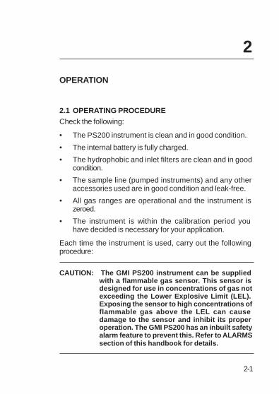
2.2 SWITCH THE INSTRUMENT ON
Press and hold the Right Hand (RH) button for one second to switch the instrument ON. Refer to Fig. 2-1.
The instrument begins its warm-up routine, which lasts approximately 30 seconds. During the warm-up, a countdown timer appears in the top (RH) corner of the display.
Note: The display backlight illuminates green and remains ON during warm-up. When warm-up is complete, the screen light automatically switches off.
2-3
OPERATION
Fig. 2-1 PS200 Switch ON
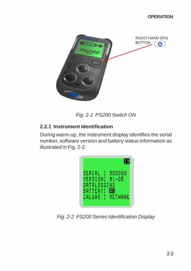
2.2.1 Instrument Identification
During warm-up, the instrument display identifies the serial number, software version and battery status information as illustrated in Fig. 2-2:
Fig. 2-2 PS200 Series Identification Display
RIGHT HAND (RH) BUTTON
2-4
USER HANDBOOK
2.2.2 Battery Status
Provides the user with the battery charge level, as shown in previous display. This will be indicated by a battery symbol with a bar graph showing FULL, 75%, 50% and 25%, which is shown continually during normal operation.
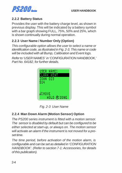
2.2.3 User Name / Number Only (Option) This configurable option allows the user to select a name or identification code, as illustrated in Fig. 2-3. This name or code will be included with all Bump, Calibration and Event logs.
Refer to ‘USER NAMES’ in ‘CONFIGURATION HANDBOOK,’ Part No. 64182, for further details.
Fig. 2-3 User Name
2.2.4 Man Down Alarm (Motion Sensor) Option
The PS200 series instrument is fitted with a motion sensor. The sensor is disabled by default but can be configured to be either selected at start-up, or always on. The motion sensor will activate an alarm if the instrument is not moved for a pre- set time.
The time period, before activation of the motion alarm, is configurable and can be set as detailed in ‘CONFIGURATION HANDBOOK’. (Refer to section 7-1: Accessories, for details of this publication).
2-5
OPERATION
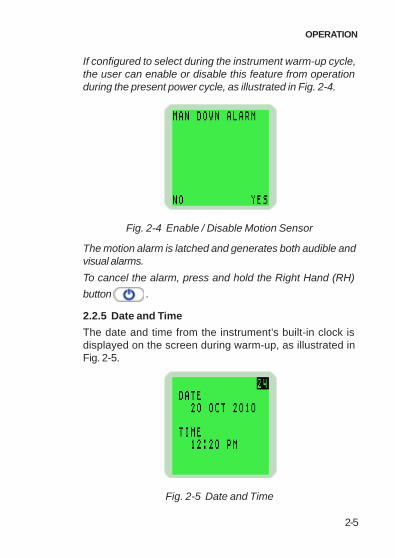
If configured to select during the instrument warm-up cycle, the user can enable or disable this feature from operation during the present power cycle, as illustrated in Fig. 2-4.
Fig. 2-4 Enable / Disable Motion Sensor
The motion alarm is latched and generates both audible and visual alarms.
To cancel the alarm, press and hold the Right Hand (RH)
button .
2.2.5 Date and Time
The date and time from the instrument’s built-in clock is displayed on the screen during warm-up, as illustrated in Fig. 2-5.
Fig. 2-5 Date and Time

2-6
USER HANDBOOK
2.2.6 Calibration Due Date
The calibration due date appears on the display, as illustrated in Fig. 2-6.
A configurable option is available not to display this screen.
Fig. 2-6 Calibration Due Date
If the Calibration Due Date has expired, the following warning is displayed:
Fig. 2-7 Calibration Overdue
Press the Right Hand (RH) button once to acknowledge that the calibration due date is overdue.

2-7
OPERATION
Press the Left Hand (LH) button once to abort the warm-up routine and automatically switch OFF the instrument.
Alternatively, a configurable option is available to force the user to switch OFF the instrument.
Further details are available from the ‘CONFIGURATION HANDBOOK’ (Part No. 64182).
2.2.7 Select Calibration Gas
This configurable option is available to allow the user to measure a different flammable gas from that which was originally used to calibrate the instrument.
This action allows the instrument software to compensate and display more accurate readings.
Fig. 2-8 Cal Gas Selection
When this option is displayed, as shown in Fig. 2.8, the gas that was originally used to calibrate the instrument is identified between two arrowheads.
Note: The instrument calibration certificate also identifies the original calibration gas type.
To select a different gas type, press the Left Hand (LH) button
to step through the available options from Methane, Propane, Butane and Pentane.
2-8
USER HANDBOOK
When the required option is highlighted, press and hold the
Right Hand (RH) button to select.
Note: Accuracy for the re-selected gas type is + 20%.
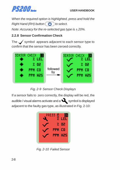
2.2.8 Sensor Confirmation Check
The symbol appears adjacent to each sensor type to confirm that the sensor has been zeroed correctly.
Fig. 2-9 Sensor Check Displays
If a sensor fails to zero correctly, the display will be red, the
audible / visual alarms activate and a symbol is displayed
adjacent to the faulty gas type, as illustrated in Fig. 2-10:
Fig. 2-10 Failed Sensor

2-9
OPERATION
To acknowledge this fault, press the Right Hand (RH) button once. This will clear the audible / visual alarm and
display a flashing spanner symbol alternating with the faulty sensor zero reading. A faulty LEL sensor zero reading is shown in Fig 2-11:
Fig. 2-11 Acknowledge Alarm
A configurable option is available to force the user to switch the instrument off if a zero fault is detected, as shown in Fig. 2-12:
Fig. 2-12 Switch OFF

2-10
USER HANDBOOK
Note: If a sensor fault is detected during normal operation of the instrument, the backlight illuminates red, an audible / visual alarm is activated immediately and a spanner symbol is shown adjacent to the faulty sensor type in the display.
2.2.9 Normal Operating Display
When warm-up is completed successfully, the backlight switches off and the normal operating screen is displayed, as illustrated in Fig. 2-13. The display varies depending on the number of sensors fitted:
1-Gas 2-Gas
3-Gas 4-Gas
Fig. 2-13 Normal Operating Display

2-11
OPERATION
2.3 SWITCH THE DISPLAY BACKLIGHT ON / OFF
The display screen backlight can be manually switched ON when working in poor lighting conditions.
Press the Right Hand (RH) button once to switch the screen backlight ON. It remains ON for 20 seconds and then automatically switches OFF.
2.4 VIEW MAXIMUM AND MINIMUM RECORDED VALUES SINCE SWITCH ON
The instrument records the maximum and minimum gas values for each sensor, since switch-on.
To view max / min values, proceed as follows:
1) Start from the normal operating display, as shown in Fig. 2-14. Press the Right Hand (RH) button once to switch the instrument backlight ON.
Fig. 2-14 Normal Operating Display
Press the Right Hand (RH) button again, while the screen light is ON, to view the maximum gas values stored in the instrument.

2-12
USER HANDBOOK
The example in Fig. 2-15 illustrates the maximum (MAX) gas values stored in a 4-gas instrument.
Fig. 2-15 Maximum Gas Values
2) Press the Right Hand (RH) button again to view the minimum gas values stored in the instrument. Note: This screen is only displayed when an Oxygen sensor is fitted in the instrument.
The example in Fig. 2-16 illustrates the minimum (MIN) gas values stored in a 4-gas instrument.
Fig. 2-16 Minimum Gas Values
2-13
OPERATION
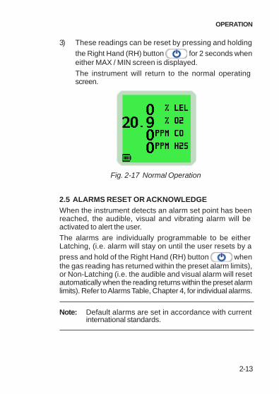
3) These readings can be reset by pressing and holding the Right Hand (RH) button for 2 seconds when either MAX / MIN screen is displayed.
The instrument will return to the normal operating screen.
Fig. 2-17 Normal Operation
2.5 ALARMS RESET OR ACKNOWLEDGE
When the instrument detects an alarm set point has been reached, the audible, visual and vibrating alarm will be activated to alert the user.
The alarms are individually programmable to be either Latching, (i.e. alarm will stay on until the user resets by a press and hold of the Right Hand (RH) button when the gas reading has returned within the preset alarm limits), or Non-Latching (i.e. the audible and visual alarm will reset automatically when the reading returns within the preset alarm limits). Refer to Alarms Table, Chapter 4, for individual alarms.
Note: Default alarms are set in accordance with current international standards.

2-14
USER HANDBOOK
2.5.1 Confidence Signal
During normal operation, the instrument sounds a confidence beep and illuminates the green LED’s briefly every 15 seconds. This function makes the user aware that the instrument is operating correctly:
Note: The confidence beep and / or LED’s can be disabled. Refer to the optional ‘CONFIGURATION HANDBOOK’ for further information (Part No. 64182)..
2.6 REMOTE SAMPLING (with pump option)
Remote sensing is possible with the internal electric pump option, or by using a hand aspirator. Connect the sample line to the sample connector at the bottom of the instrument.
On pumped models, the pump is OFF after start-up.
Warning (Hand Aspirator): The PS200 Series is designed to be used with a built-in pump for remote sampling. A hand aspirator can be used for indicative sampling, but it must be noted that when using a hand aspirator, a reading error in the region of + 20% is possible. In addition, whereas the pump can sample quickly and accurately with up to 30 metres of sample line, the hand aspirator must only be used with up to 10 metres of sample line and the sample time is extended.
2-15
OPERATION
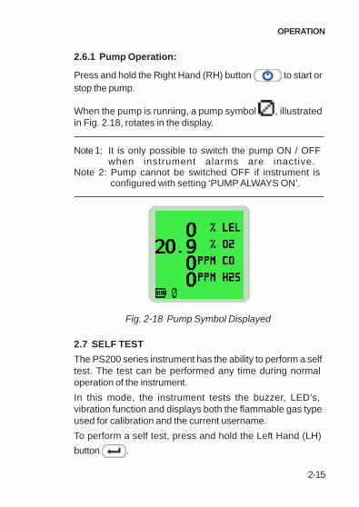
2.6.1 Pump Operation:
Press and hold the Right Hand (RH) button to start or stop the pump.
When the pump is running, a pump symbol , illustrated in Fig. 2.18, rotates in the display.
Note 1: It is only possible to switch the pump ON / OFF when instrument alarms are inactive.
Note 2: Pump cannot be switched OFF if instrument is configured with setting ‘PUMP ALWAYS ON’.
Fig. 2-18 Pump Symbol Displayed
2.7 SELF TEST
The PS200 series instrument has the ability to perform a self test. The test can be performed any time during normal operation of the instrument.
In this mode, the instrument tests the buzzer, LED’s, vibration function and displays both the flammable gas type used for calibration and the current username.
To perform a self test, press and hold the Left Hand (LH)
button .

2-16
USER HANDBOOK
2.8 SWITCH THE INSTRUMENT OFF
Press and hold both the Left Hand (LH) button and the Right Hand (RH) button to switch the instrument OFF.
The instrument display starts a countdown from three (3) to OFF. Both buttons must be pressed together until the dis-play goes blank.
Fig. 2-19 Switch OFF
While both buttons are pressed, the audible alarm sounds every second to alert user that the instrument is switching OFF.

3-1
MANUAL BUMP TEST
MANUAL BUMP TEST
3.1 BACKGROUND
A bump test verifies sensor response and alarm operation by exposing the instrument to a known concentration of gas. The PS200 series of instruments can be bump tested either manually or automatically (using the Auto Bump / Calibration Station) .
This chapter details how instruments can be manually bump tested to ensure the readings provided are accurate and provide the user with immediate warning of a potentially hazardous situation.
To facilitate manual bump testing, a test kit (Part No. 64121) is available and contains the necessary test gas, regulator and Tygon® tubing to ensure a proper bump test is performed.
CAUTION: When performing a bump test, the test gas concentration should be high enough to trigger the instrument’s alarms. Should any instrument fail a bump test, then a full calibration must be performed.
3
3-2
USER HANDBOOK
3.2 MANUAL BUMP OPTIONS
The PS200 series provides two bump test options, QUICK and FULL.
The QUICK bump test validates that the alarm threshold has been exceeded for each range.
The FULL bump test checks the response of all ranges against set limits.
The QUICK bump test is configured by default.
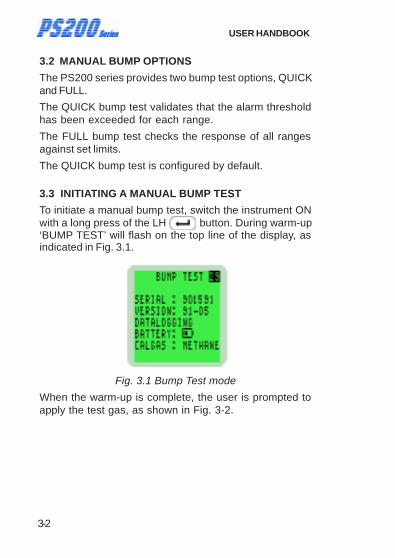
3.3 INITIATING A MANUAL BUMP TEST
To initiate a manual bump test, switch the instrument ON with a long press of the LH button. During warm-up ‘BUMP TEST’ will flash on the top line of the display, as indicated in Fig. 3.1.
Fig. 3.1 Bump Test mode
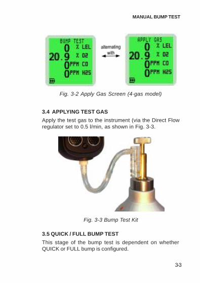
When the warm-up is complete, the user is prompted to apply the test gas, as shown in Fig. 3-2.
3-3
MANUAL BUMP TEST
Fig. 3-2 Apply Gas Screen (4-gas model)
3.4 APPLYING TEST GAS
Apply the test gas to the instrument (via the Direct Flow regulator set to 0.5 l/min, as shown in Fig. 3-3.
Fig. 3-3 Bump Test Kit
3.5 QUICK / FULL BUMP TEST
This stage of the bump test is dependent on whether QUICK or FULL bump is configured.

3-4
USER HANDBOOK
3.5.1 Quick Bump Test
As the alarm threshold for each range is exceeded, the audible / visual / vibration alarms will activate and a symbol will appear, otherwise a symbol will be displayed.
3.5.2 Full Bump Test
After a short period of time, the gas readings are checked against configurable limits. The audible / visual / vibration alarms will activate and a symbol will appear if the readings are within these limits, otherwise a symbol will be displayed.
3.6 ALARM CONFIRMATION
The user is then prompted to confirm if the audible and visual alarms were activated, as shown in Fig. 3-4
Fig. 3-4 Confirm Alarms (4-gas model)
Note: The audible, visual and vibrating alarms activate for 2 seconds only (default setting) when activated during the bump test.

3-5
MANUAL BUMP TEST
3.7 BUMP TEST RESULT
After selecting ‘YES’ or ‘NO’ the user is informed of theoverall bump test result as shown in Fig. 3-5.
Fig. 3-5 Bump Test PassThe bump test gas should now be removed.The bump test result including date and time will be auto-matically datalogged.When the gas readings fall below their alarm set-points,or after 60 seconds, the bump test is complete, and theinstrument will automatically return to normal operation.Should any gas range fail the bump test, the display willbe red and a symbol will be displayed as shown inFig. 3-6.
Fig. 3-6 Bump Test Fail If an instrument fails a bump test, then a full recalibrationwill be necessary.

3-6
USER HANDBOOK

4-1
ALARMS
ALARMS
4.1 GAS ALARMS
Gas alarms are enabled when the instrument is switched on and warm-up is complete.
All gas ranges have alarm limits that trigger the alarm if the measured gas value exceeds the set level. If a preset alarm level is exceeded, the instrument vibrates, the display backlight illuminates red, the audible alarm sounds, the LED’s flash red and the gas range in alarm flashes on the display.
The alarms are individually programmable to be either ‘Latching’ or ‘Non-Latching’.
A ‘Latching’ alarm will stay on until reset by the user with a press and hold of the Right Hand (RH) button when the gas readings are safe.
A ‘Non-Latching’ alarm will reset automatically when the gas readings are safe.
The following table illustrates the factory default alarm indications:
4

4-2
USER HANDBOOK
EPYTMRALA GNIHCTAL ETUM ELBIDUA GNITARBIV LAUSIV)DELDER(
)IH(LEL delbasiD delbasiD neriS A/N wolSgnihsalF
)IHIH(LEL seY delbasiD neriS seY gnihsalF
O2 ( )IHIH seY delbasiD neriS seY gnihsalF
O2 )OL( delbasiD delbasiD neriS A/N wolSgnihsalF
O2 )OLOL( seY delbasiD neriS A/N gnihsalF
)IH(1cixoT delbasiD delbasiD neriS A/N wolSgnihsalF
)IHIH(2cixoT seY delbasiD neriS seY gnihsalF
)LETS(3cixoT seY delbasiD neriS seY gnihsalF
4cixoT)AWT/LETL(
seY delbasiD neriS seY gnihsalF
tluaFyrettaBwoL A/N A/N ralugeRpeeB
A/N wolSgnihsalF
tluaForeZ A/N A/N ralugeRpeeB
A/N wolSgnihsalF
rosneS tluaF A/N A/N ralugeRpeeB
A/N wolSgnihsalF
wolFwoL)ylnO.rtsnIdepmuP(
A/N A/N ralugeRpeeB
A/N wolSgnihsalF
tluaFwolF)ylnO.rtsnIdepmuP(
A/N A/N ralugeRpeeB
A/N gnihsalF
noitarbilaCderiuqeR
A/N A/N ralugeRpeeB
A/N wolSgnihsalF
deripxEnoitarbilaC A/N A/N ralugeRpeeB
A/N wolSgnihsalF
)LEL(egnaRrevO seY A/N neriS seY gnihsalF
N/A = Not Applicable
PS200 Series (Default) Alarm Indications
4-3
ALARMS
4.1.1 Flammable LEL Alarm Limit
Two alarm levels, ‘HI’ and ‘HIHI’, are available, each with different pitch and tone. All alarms are user configurable to meet the specific needs of different companies.
4.1.2 Over-Range Flammable Gas Alarm Function
The flammable sensor is designed for use in the LEL range only. Exposure to high concentrations of flammable gas, such as lighter fuel, can damage the flammable sensor. If the flammable gas readings exceed 120% LEL, a safety alarm will be activated. The instrument should then be switched OFF and returned to fresh air.
4.1.3 Oxygen (O2) Alarm Limits
Three alarm levels, ‘HI’, ‘LO’ and ‘LOLO’ are available, each with different pitch and tone. All alarms are user configurable to meet the specific needs of the end user.
4.1.4 Toxic Alarm Limits
When operating normally, the instrument calculates the Short Term Exposure Limit (STEL) and Long Term Exposure Limit (LTEL), known as Time Weighted Average (TWA) readings, for each toxic gas range alarm. TWA alarms are programmable for each toxic range fitted to the instrument. Additionally, two alarm levels ‘HI’ and ‘HI HI’ are available.
Note: A Time Weighted Average (TWA) value is the mean average gas level over a specific period. The STEL is 15 minutes and the LTEL is 8 hours. Typically, TWA alarms make the instrument single user applicable. An option is available to restart the averaging after each instrument switch-off, thus allowing for multiple user application.
4-4
USER HANDBOOK
Note: The toxic gas alarm levels – instantaneous, STEL and LTEL are set at the time of instrument manufacture. It is important that the user ensures that the levels are in accordance with their company’s alarm levels and with health and safety legislation. The alarm levels may be changed, if required, via the instrument set up software, or as detailed in the optional ‘CONFIGURATION HANDBOOK’ (Part No. 64182).
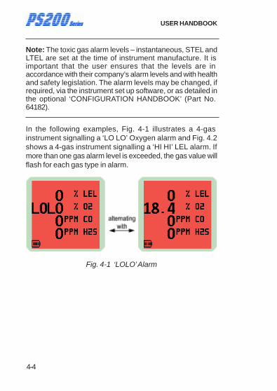
In the following examples, Fig. 4-1 illustrates a 4-gas instrument signalling a ‘LO LO’ Oxygen alarm and Fig. 4.2 shows a 4-gas instrument signalling a ‘HI HI’ LEL alarm. If more than one gas alarm level is exceeded, the gas value will flash for each gas type in alarm.
Fig. 4-1 ‘LOLO’ Alarm

4-5
ALARMS
Fig. 4-2 ‘HIHI’ Alarm
Note: See the ‘CONFIGURATION HANDBOOK’ for further information. (Part No. 64182)
4.2 ACKNOWLEDGE GAS ALARMS
Once in a safe area, or the gas reading has returned within the preset limits, press and hold the Right Hand (RH) button
to mute the alarm sounder and extinguish the gas LED’s.
4.3 MUTE ALARMS
If configured, a muted alarm will be silenced for 60 seconds.
Mute ‘disabled’ cannot silence the alarm until gas falls below the alarm level.
If alarm configuration allows muting of audible alarm, the following applies:
Non-latching: Once alarm has been muted, the audible alarm is cancelled for a period of 60 seconds, and if gas concentration during that time falls below alarm set point, the visual alarm clears automatically.
4-6
USER HANDBOOK
Latching: If audible alarm has been muted and if gas concentration during that time falls below alarm set point, visual alarm requires to be acknowledged to clear.
4.4 HIGH FLAMMABLE GAS OVER-RANGE ALARM
Caution: Exposing the LEL sensor to concentrations of flammable gas above 100% LEL can damage the sensor.
In order to protect the user from danger in the event of the flammable gas (LEL) sensor being over exposed to a high concentration of flammable gas, the instrument has an over- range alarm.
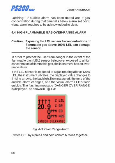
If the LEL sensor is exposed to a gas reading above 120% LEL, the instrument vibrates, the displayed value changes to 4 rising arrows, the backlight illuminates red, the tone of the audible alarm changes, and the visual alarm LED’s flash quickly. The flashing message ‘DANGER OVER RANGE’ is displayed, as shown in Fig 4-3:
Fig. 4-3 Over Range Alarm
Switch OFF by a press and hold of both buttons together.
4-7
ALARMS
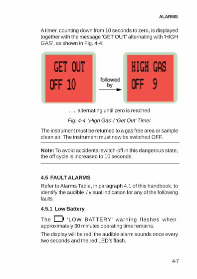
A timer, counting down from 10 seconds to zero, is displayed together with the message ‘GET OUT’ alternating with ‘HIGH GAS’, as shown in Fig. 4-4:
. . . alternating until zero is reached
Fig. 4-4 ‘High Gas’ / ‘Get Out’ Timer
The instrument must be returned to a gas free area or sample clean air. The instrument must now be switched OFF.
Note: To avoid accidental switch-off in this dangerous state, the off cycle is increased to 10 seconds.
4.5 FAULT ALARMS
Refer to Alarms Table, in paragraph 4.1 of this handbook, to identify the audible / visual indication for any of the following faults.
4.5.1 Low Battery
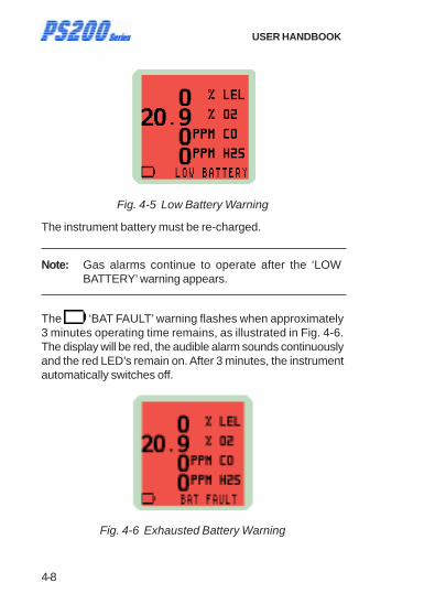
The ‘LOW BATTERY’ warning flashes when approximately 30 minutes operating time remains.
The display will be red, the audible alarm sounds once every two seconds and the red LED’s flash.
4-8
USER HANDBOOK
Fig. 4-5 Low Battery Warning
The instrument battery must be re-charged.
Note: Gas alarms continue to operate after the ‘LOW BATTERY’ warning appears.
The ‘BAT FAULT’ warning flashes when approximately 3 minutes operating time remains, as illustrated in Fig. 4-6. The display will be red, the audible alarm sounds continuously and the red LED’s remain on. After 3 minutes, the instrument automatically switches off.
Fig. 4-6 Exhausted Battery Warning
4-9
ALARMS
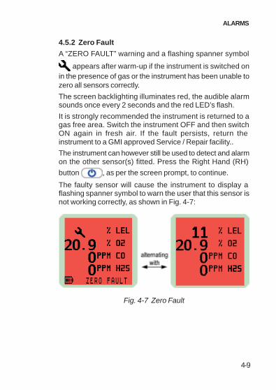
4.5.2 Zero Fault
A “ZERO FAULT” warning and a flashing spanner symbol
appears after warm-up if the instrument is switched on in the presence of gas or the instrument has been unable to zero all sensors correctly.
The screen backlighting illuminates red, the audible alarm sounds once every 2 seconds and the red LED’s flash.
It is strongly recommended the instrument is returned to a gas free area. Switch the instrument OFF and then switch ON again in fresh air. If the fault persists, return the instrument to a GMI approved Service / Repair facility..
The instrument can however still be used to detect and alarm on the other sensor(s) fitted. Press the Right Hand (RH)
button , as per the screen prompt, to continue.
The faulty sensor will cause the instrument to display a flashing spanner symbol to warn the user that this sensor is not working correctly, as shown in Fig. 4-7:
Fig. 4-7 Zero Fault
4-10
USER HANDBOOK
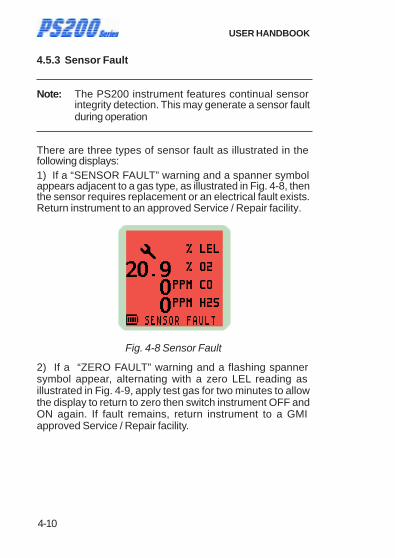
4.5.3 Sensor Fault
Note: The PS200 instrument features continual sensor integrity detection. This may generate a sensor fault during operation
There are three types of sensor fault as illustrated in the following displays: 1) If a “SENSOR FAULT” warning and a spanner symbol appears adjacent to a gas type, as illustrated in Fig. 4-8, then the sensor requires replacement or an electrical fault exists. Return instrument to an approved Service / Repair facility.
Fig. 4-8 Sensor Fault
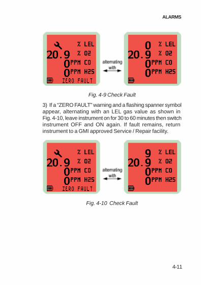
2) If a “ZERO FAULT” warning and a flashing spanner symbol appear, alternating with a zero LEL reading as illustrated in Fig. 4-9, apply test gas for two minutes to allow the display to return to zero then switch instrument OFF and ON again. If fault remains, return instrument to a GMI approved Service / Repair facility.
4-11
ALARMS
Fig. 4-9 Check Fault
3) If a “ZERO FAULT” warning and a flashing spanner symbol appear, alternating with an LEL gas value as shown in Fig. 4-10, leave instrument on for 30 to 60 minutes then switch instrument OFF and ON again. If fault remains, return instrument to a GMI approved Service / Repair facility.
Fig. 4-10 Check Fault

4-12
USER HANDBOOK
4.5.4 Low Flow - (Pumped instruments only)
If there is a restricted flow, a “LOW FLOW” warning flashes in the display, the display will be red and both audible alarm and red LED’s will be activated.
In this alarm condition, the pump symbol is not displayed. Refer to example Fig. 4.11.
Fig. 4-11 Low Flow
Check maximum sample line length (30 metres) is not exceeded and check sample filter or probe for blockage, if applicable.
4.5.5 Flow Fault (Pumped Instruments Only)
If a flow fail or sample fault exists, a ‘FLOW FAULT’ warning is displayed, as illustrated in Fig. 4-12. The display will be red and both the audible alarm and red LED’s will be activated.
Check sample line, filter or probe for blockage, if applicable. Clear the blockage then restart the pump by a press and hold
of the Right Hand (RH) button .

4-13
ALARMS
Fig. 4-12 Flow Fault
4.5.6 Calibration Required
If the instrument requires calibration then during warm-up, a ‘CALIBRATION OVERDUE’ warning is displayed. The instrument will operate using its previous calibration settings, however, as the sensors response may have diminished, the instrument should be recalibrated and tested.
Fig. 4-13 Calibration Overdue
Press the Right Hand (RH) button once to acknowledge that calibration due date is overdue, cancel the audible / visual alarm, and continue to the next display. A ‘CAL EXPIRED’ warning, red backlighting and red LED’s will flash every 30 seconds.
4-14
USER HANDBOOK
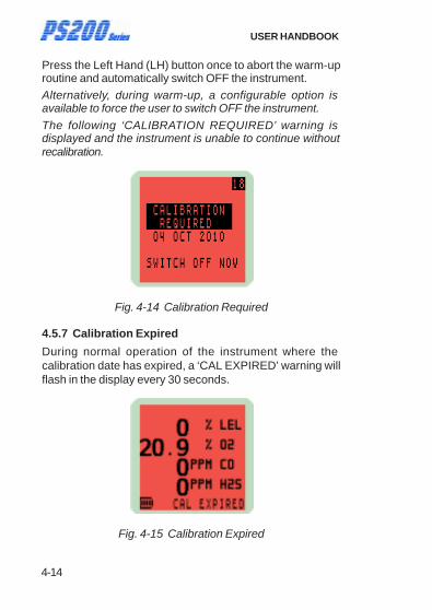
Press the Left Hand (LH) button once to abort the warm-up routine and automatically switch OFF the instrument.
Alternatively, during warm-up, a configurable option is available to force the user to switch OFF the instrument.
The following ‘CALIBRATION REQUIRED’ warning is displayed and the instrument is unable to continue without recalibration.
Fig. 4-14 Calibration Required
4.5.7 Calibration Expired
During normal operation of the instrument where the calibration date has expired, a ‘CAL EXPIRED’ warning will flash in the display every 30 seconds.
Fig. 4-15 Calibration Expired

4-15
ALARMS
4.6 MAN DOWN ALARM (MOTION SENSOR)
The motion sensor alarm can be configured ‘NOT USED’ (default), ‘ALWAYS ON’ , or ‘SELECT AT START’ .
The sensor will activate an alarm if the instrument is not moved for a pre-set period, configurable from 30 seconds to 5 minutes in 30 second increments.
The motion sensor alarm is ‘latched’ and must be acknowledged to clear.
When an alarm condition is activated, the display backlight flashes red, the audible alarm sounds once every two seconds, and the warning red LED’s will flash.
A typical display is shown in Fig. 4-16.
Fig. 4-16 Motion Sensor Alarm
To cancel the alarm, press and hold the Right Hand (RH)
button after the instrument is handled / moved.

4-16
USER HANDBOOK

5-1
OPERATOR MAINTENANCE
OPERATOR MAINTENANCE
5.1 CLEANING
CAUTION: Do not use polishes containing silicon or solvent to clean the instrument as these may damage the flammable gas sensor (if fitted). Do not use abrasive materials or strong volatile chemical solutions as these could damage the impact resistant casing.
The outer, impact resistant, casing of the PS200 Series instrument may be cleaned using a non-abrasive moist cloth. Rub the cloth over the outer casing to remove any dirt and grime.
In extreme cases, a mild soap solution may be used with a non-abrasive cloth to remove any stubborn marks.
5.2 REPLACE INSTRUMENT FILTERS
The instrument has 2 filters protecting the instrument from contamination. A hydrophobic filter is located behind the filter cover on the front face of the instrument. The sample inlet (dust) filter is located in the sample inlet connector at the bottom of the instrument. The filters should be inspected periodically for contamination or damage.
To inspect / replace the filters, proceed as follows:
5
5-2
USER HANDBOOK
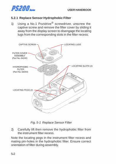
5.2.1 Replace Sensor Hydrophobic Filter
1) Using a No.1 Pozidrive® screwdriver, unscrew the captive screw and remove the filter cover by sliding it away from the display screen to disengage the locating lugs from the corresponding slots in the filter recess.
LOCATING PEGS (2)
LOCATING SLOTS (2)
CAPTIVE SCREW LOCATING LUGS
HYDROPHOBICFILTER
(Part No. 64254)
FILTER COVERASSEMBLY
(Part No. 64240)
Fig. 5-1 Replace Sensor Filter
2) Carefully lift then remove the hydrophobic filter from the instrument filter recess.
Note the locating pegs in the instrument filter recess and mating pin-holes in the hydrophobic filter. Ensure correct orientation of filter during assembly.
5-3
OPERATOR MAINTENANCE
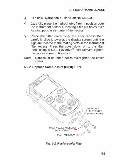
3) Fit a new Hydrophobic Filter (Part No. 64254).
4) Carefully place the hydrophobic filter in position over the instrument sensors, locating filter pin holes over locating pegs in instrument filter recess.
5) Place the filter cover over the filter recess then carefully slide it towards the display screen until the lugs are located in the mating slots in the instrument filter recess. Press the cover down on to the filter then, using a No.1 Pozidrive® screwdriver, tighten the captive screw until secure.
Note: Care must be taken not to overtighten the cover screw.
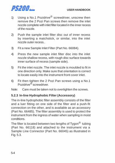
5.2.2 Replace Sample Inlet (Dust) Filter
SAMPLE INLET FILTER
(Part No. 64084)
INLET NOZZLE ASSEMBLYQUICK CONNECT
POZI PAN SCREW (2)
Fig. 5-2 Replace Inlet Filter
5-4
USER HANDBOOK
1) Using a No.1 Pozidrive® screwdriver, unscrew then remove the 2 Pozi Pan screws then remove the inlet nozzle complete with inlet filter located in the inner recess of the nozzle.
2) Push the sample inlet filter disc out of inner recess by inserting a matchstick, or similar, into the inlet nozzle outer recess..
3) Fit a new Sample Inlet Filter (Part No. 66084).
4) Press the new sample inlet filter disc into the inlet nozzle shallow recess, with rough disc surface towards inner surface of recess (sample side).
5) Fit the inlet nozzle. The inlet nozzle is moulded to fit in one direction only. Make sure that orientation is correct to locate easily into the instrument front cover inlet.
6) Fit then tighten the 2 Pozi Pan screws using a No.1 Pozidrive® screwdriver.
Note: Care must be taken not to overtighten the screws.
5.2.3 In-line Hydrophobic Filter (Accessory)
The in-line hydrophobic filter assembly consists of the filter and a luer fitting on one side of the filter and a push-fit connection on the other, and is available as an accessory (Part No. 66485). The filter assembly is used to protect the instrument from the ingress of water when sampling in moist conditions.
The filter is located between two lengths of Tygon® tubing
(Part No. 66118) and attached to the instrument via a Sample Line Connector (Part No. 66045) as illustrated in Fig. 5.3.

5-5
OPERATOR MAINTENANCE
Fig. 5.3 In-line Hydrophobic Filter
To replace the filter, proceed as follows:
1) Unscrew the luer fitting from one side of the the filter in a counter clockwise direction, detach the tubing from the other side then remove the hydrophobic filter.
Note: If re-fitting the same filter, make sure that filter direction of flow orientation is maintained. This can be easily identified by position of yellow label on filter, i.e. facing instrument.
2) Fit a new In-line Hydrophobic Filter (Part No. 66484). Note that the filter should be fitted with the yellow label facing the instrument.
3) Attach the luer fitting, with sample line attached, to the mating side of the filter then tighten in a clockwise direction to secure. Do not overtighten the fitting.
4) Attach the sample line to the other side of the filter making sure that it is securely fitted.

5-6
USER HANDBOOK

6-1
OPERATOR MAINTENANCE
RECHARGE BATTERY
6.1 RECHARGE INSTRUMENT BATTERY
Use only GMI chargers to recharge PS200 series instruments.
CAUTION: Switch the instrument off when charging the internal battery.
The battery should be recharged in the following situations:
• The ‘LOW BATTERY’ flag appears on the display
• The instrument will not switch On
When the ‘LOW BATTERY’ icon appears on the display, there is approximately 30 minutes operation left at normal temperatures. The instrument will then switch Off automatically.
There are three options available to the user to charge the PS200 instrument battery, as follows:
1) Using the Charging Comms Clip (Part No. 64260) together with the Mains Adaptor and cable (Part No. 64247) supplied with the instrument.
2) Charging the instrument in the Auto Bump / Calibration Station (Part No. 64122 / 64122Q).
6

6-2
USER HANDBOOK
3) Using the 12V - USB Vehicle Charging Adaptor (Part No. 64248)
In all three options:
Once the charger is connected, charging will commence automatically.
During charging, the battery symbol and ‘CHARGING’ indication flashes in the display. Maximum recharge duration is 4 hours allowing minimum instrument run times.
On completion of charging, the ‘full’ battery symbol is displayed together with ‘CHARGING COMPLETE’ indication.
The instrument will not be damaged if left connected to a charger.
6.1.1 Recharge Instrument using the Charging / Comms Clip
The charging / comms clip (Part No. 64260), together with the cable (supplied with Mains Adaptor), enables the instrument battery to be charged by connecting the instrument to any of the following power sources:
- 5v USB Mains Adaptor (Part No. 64247)
- USB port of a Personal Computer (PC) or Laptop
- 12v - USB Vehicle Adaptor (Part No. 64248)
The clip is easily connected to the instrument charging contact pads and features a mini-USB socket to enable connection of mini-USB charging / comms cable with a standard type USB connector at the other end.
To connect charging / comms clip to the instrument, push the clip in direction of arrows as illustrated, engaging tongue on clip in instrument locating slot until firmly seated.

6-3
OPERATOR MAINTENANCE
Fit standard type USB connector to power source, as selected from list above.
On completion of charging, disconnect standard type USB connector from power source then mini-USB from clip. Grip charging / comms clip and firmly pull away from instrument until tongue on clip disengages with location slot in instrument.
CONTACTPADS (4)
LOCATING SLOT
LOCATING TONGUE
CHARGING / COMMS CLIP(Part No. 64260)
MINI USB SOCKET
Fig. 6-1 Charging Cable Connection

6-4
USER HANDBOOK
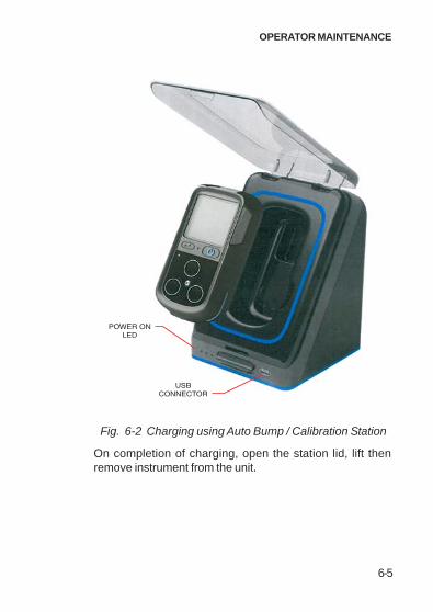
6.1.2 Recharge Instrument using the Automatic Bump / Calibration Station
The Automatic Bump / Calibration Station (Part No. 64122 / 64122Q) enables both instrument battery charging and automatic bump testing and calibration of PS200 series instruments to verify that they are suitable for use.
The Auto Bump / Calibration Station will accommodate the PS200 series instrument with or without protective rubber boot fitted.
Open the lid of the station, illustrated in Fig. 6-2, then insert instrument, ensuring that it is firmly seated in unit before closing the lid.
6-5
OPERATOR MAINTENANCE
USBCONNECTOR
POWER ONLED
Fig. 6-2 Charging using Auto Bump / Calibration Station
On completion of charging, open the station lid, lift then remove instrument from the unit.

6-6
USER HANDBOOK
7-1
CALIBRATION
CALIBRATION
7.1 GENERAL DESCRIPTION
The instrument has been calibrated for particular gases. Where any doubt exists the product should be returned to GMI or an authorised distributor for calibration.
WARNING: The instrument must be calibrated and configured by authorised personnel only.
Two methods of calibration are possible:
• Field Calibration. See ‘CONFIGURATION HANDBOOK’ for further details. (Part No. 64182)
• The GMI Automatic Bump / Calibration Station (Part No. 64122 / 64122Q) provides controlled delivery of gases permitting users to bump test and calibrate the instrument in a controlled manner whilst maintaining a record of calibration results on a PC.
Note: The detailed calibration methods, consisting of both hardware and software, are manufactured by GMI. For further details contact GMI or an authorised distributor.
7
7-2
USER HANDBOOK
7.2 CALIBRATION VALIDITY
Calibration validity remains the responsibility of the user. Under normal operating conditions a 12 month period can be expected. This is no guarantee, however, as the precise application of the product is unknown to GMI. Individual codes of practice will dictate shorter periods.
Regular calibration establishes a pattern of reliability and enables the calibration check period to be modified in line with operational experience. As a guide, the higher the risk, the more frequently calibration should be checked.

8-1
ACCESSORIES
ACCESSORIES
Accessories supplied with the instrument
Part Number Description
64260 Charging / Comms Clip (mini-USB)
64247 Mains Adaptor (c/w USB / mini-USB cable)
64171 User Handbook (CD-ROM)
64172 Quick Operating Instructions
66136 Sample Line Connector - Pumped Instruments Only. (c/w 3.0 metres Tygon® Tubing)
Additional accessories available for the instrument
Part Number Description
64100 Plastic Carrying Case (Instrument + Accessories)
64102 CalGas Carrying Case (Capacity - 2 Cylinders)
64303 Rubber Boot (Instrument)
66485 In-Line Hydrophobic Filter Assy.
66484 Hydrophobic Filter (for 66085)
66084 Sample Inlet Filter
66123 Hand Aspirator
8

8-2
USER HANDBOOK
Part Number Description
66478 Hand Aspirator (c/w 3.0 metres Tygon® Tubing)
66118 Tygon® Tubing - per metre
66112 Sample Line Extender
66485 In-Line Hydrophobic Filter Assy.
66545 Ball Float
Charging Accessories Part Number Description
64248 In-Vehicle Charging Adaptor (12v - USB)
Manual Bump / Field Calibration Kit Part Number Description
64121 Manual Bump Kit (c/w Combi Test Gas 99146, Direct Flow regulator, tubing & sample line connector)
Automatic Bump / Calibration Accessory Part Number Description
64122 Automatic Bump / Calibration Station (6mm. fittings & incl. PSU / USB / Software)
64122Q Automatic Bump / Calibration Station (1/4 in. fittings & incl. PSU / USB / Software)

8-3
ACCESSORIES
Gas Kits for Auto Bump / Calibration Station
(Cylinder / Regulator / Tubing) Part Number Description
99146 Combi Test Gas (2.5% CH4, 500ppm CO, 50ppm H2S, 18%O2, balance N2.
64133 Auto Bump / Calibration Kit (Combi Test Gas 99146, Demand Flow regulator c/w 6mm tubing).
64133Q Auto Bump / Calibration Kit (Combi Test Gas 99146, Demand Flow regulator c/w 1/4 in. tubing).
Documentation Part Number Description
64171 User Handbook (CD-ROM)
64172 Quick Operating Instructions
64182 Configuration & Field Calibration Handbook (CD-ROM)
64173 Maintenance Manual (CD-ROM)
Software Part Number Description
64500 Datalogging

8-4
USER HANDBOOK

9-1
ADDITIONAL INFORMATION
9
ADDITIONAL INFORMATION
9.1 TRAINING
Training courses are available on all GMI products. Contact GMI Marketing Department for further details:
Tel: +44 (0) 141 812 3211
Fax: +44 (0) 141 812 7820
e-mail: [email protected]
9.2 WORLD WIDE WEB
Visit GMI web site at www.gmiuk.com
Visit GMI (USA) web site at www.gmiusa.com

9-2
USER HANDBOOK

i
INDEX
INDEX
A
ACCESSORIES 8-1
ACKNOWLEDGE 2-13
ACKNOWLEDGE GAS ALARMS 4-5
ADDITIONAL INFORMATION 9-1
ALARM CONFIRMATION 3-4
ALARMS 4-1
ALARMS, FAULT 4-7
ALARMS, GAS 4-1, 4-5
ALARMS, MUTE 4-5
ALARMS RESET OR ACKNOWLEDGE 2-13
APPLYING TEST GAS 3-3
AREAS OF USE ii
Automatic Calibration 7-1
B
BACKLIGHT, DISPLAY 2-11
BAT 6-1
BATTERY, INSTRUMENT 6-1
Battery, Low 4-7
BATTERY, RECHARGE 6-1
Battery Status 2-4
BUMP OPTIONS 3-2
BUMP TEST 3-1
BUMP TEST RESULT 3-5
C
CALIBRATION 7-1
Calibration, Automatic 7-1
Calibration Due Date 2-6
Calibration Expired 4-15
Calibration, Field 7-1
Calibration Gas 2-7
Calibration Required 4-13
CALIBRATION VALIDITY 7-2
CERTIFICATION 1-8
Certification Marks 1-8
CLEANING 5-1
ii
USER HANDBOOK
CONFIDENCE BEEP 2-14
Confidence Signal 2-14
CONFIRMATION, ALARM 3-4
CONSTRUCTION 1-6
COPYRIGHT i
D
DATA LOGGING 1-5
Date 2-5
DESCRIPTION, GENERAL 1-1
DISPLAY BACKLIGHT ON / OFF 2-11
Display, Operating 2-10
DISPOSAL ADVICE i
E
EN50054 1-6
Environment 1-7
Expired, Calibration 4-15
F
FAULT ALARMS 4-7
Fault, Flow 4-12
Fault, Sensor 4-10
Fault, Zero 4-9
FEATURES 1-4
Field Calibration 7-1
Filter, Hydrophobic 5-2
FILTERS 1-6
FILTERS, INSTRUMENT 5-1
Flammable LEL Alarm Limit 4-3
Flow Fault 4-12
Flow, Low 4-12
FULL BUMP TEST 3-4
G
GAS ALARMS 4-1, 4-5
Gas, Calibration 2-7
GAS OVER-RANGE ALARM 4-6
GAS, TEST 3-3
GENERAL DESCRIPTION 1-1
H
HANDLING ii
HIGH FLAMMABLE GAS OVER-RANGE ALARM 4-6
Hydrophobic Filter 5-2
iii
INDEX
I
Identification, Instrument 2-3
IDENTIFICATION LABEL 1-7
In-line Hydrophobic Filter (Accessory) 5-4, 6-2, 6-4
INFORMATION, ADDI-TIONAL 9-1
INITIATING A MANUAL BUMP TEST 3-2
Inlet (Dust) Filter 5-3
INSTRUMENT BATTERY 6-1
INSTRUMENT FILTERS 5-1
Instrument Identification 2-3
INSTRUMENT OFF 2-16
INSTRUMENT ON 2-2
INTRODUCTION 1-1
IP65 1-6
L
LABEL, IDENTIFICATION 1-7
LEL Alarm Limit 4-3
LIABILITY i
LOGGING, DATA 1-5
Low Battery 4-7
Low Flow 4-12
LTEL 4-3
M
MAINTENANCE, OPERATOR 5-1
Man Down Alarm (Motion Sensor) Option 2-4
MANUAL BUMP OP-TIONS 3-2
MANUAL BUMP TEST 3-1, 3-2
Marks, Certification 1-8
MAXIMUM 2-11
MINIMUM 2-11
MODIFICATION NOTICES i
MOTION SENSOR 4-15
Motion Sensor 2-4
MUTE ALARMS 4-5
N
Name, User 2-4
Normal Operating Display 2-10
iv
USER HANDBOOK
O
OFF, INSTRUMENT 2-16
ON, INSTRUMENT 2-2
Operating Display 2-10
OPERATING PROCEDURE 2-1
OPERATION 2-1
OPERATOR MAINTENANCE 5-1
Option, Pump 2-15
OPTIONS, BUMP 3-2
OVER-RANGE ALARM 4-6
Over-Range Flammable Gas Alarm Function 4-3
Oxygen (O2) Alarm Limits 4-3
P
Performance 1-9
PHYSICAL PROPERTIES 1-7
PROCEDURE, OPERATING 2-1
PROPERTIES, PHYSICAL 1-7
Pump Option 2-15
Q
QUICK / FULL BUMP TEST 3-3
QUICK BUMP TEST 3-4
R
RECHARGE BATTERY 6-1
RECHARGE INSTRUMENT BATTERY 6-1
REMOTE SAMPLING 2-14
REPLACE INSTRUMENT FILTERS 5-1
Replace Sample Inlet (Dust) Filter 5-3
Replace Sensor Hydrophobic Filter 5-2
Required, Calibration 4-13
RESET, ALARMS 2-13
RESULT, TEST 3-5
S
SAFETY ii
Sample Inlet (Dust) Filter 5-3
SAMPLING, REMOTE 2-14

v
INDEX
Select Calibration Gas 2-7
SELF TEST 2-15
Sensor Confirmation Check 2-8
Sensor Fault 4-10
Sensor Hydrophobic Filter 5-2
SENSOR, MOTION 4-15
Sensor, Motion 2-4
Signal, Confidence 2-14
SOFTWARE i
Status, Battery 2-4
STEL 4-3
STORAGE ii
T
TEST, BUMP 3-1
TEST GAS 3-3
TEST RESULT 3-5
TEST, SELF 2-15
Time 2-5
Toxic Alarm Limits 4-3
TRAINING 9-1
TRANSIT ii
TWA 4-3
U
User Name / Number Only (Option) 2-4
V
VALIDITY, CALIBRATION 7-2
W
warm-up 2-3
WORLD WIDE WEB 9-1
Z
Zero Fault 4-9

vi
USER HANDBOOK


GMI Head Office:
Inchinnan Business Park, Renfrew, PA4 9RG, Scotland, U.K. Telephone +44 (0)141 812 3211 Fax +44 (0)141 812 7820 e-mail: [email protected] http://www.gmiuk.com
GMI USA Office:
930 Interstate Ridge Drive, Suite H, Gainesville GA 30501, USA Telephone (678) 928 4900 Fax (678) 928 4906 e-mail: [email protected]
GMI Service & Calibration Division:
25 Cochran Close, Crownhill, Milton Keynes, MK8 OAJ, England, U.K. Telephone +44 (0)1908 568867 Fax +44 (0)1908 261056 e-mail: [email protected]