gbx fr408 reference backplane overview-rev1 - ieee · pdf filepair layer channel construction...
TRANSCRIPT
GBX FR408 REFERENCE BACKPLANE
MOLEX INCORPORATED 2222 WELLINGTON COURT, LISLE, IL 60532-1682
TEL 630-969-4550 FAX 630-969-4550 TLX 254069
Page 1
GBX FR408 Reference Backplane
Layout and Design Overview
Date: November 30, 2004 Revision: 1.2
By Gourgen Oganessyan Sr Electrical Project Engineer [email protected] phone: (630) 527-4287 fax: (630) 512-8620
GBX FR408 REFERENCE BACKPLANE
MOLEX INCORPORATED 2222 WELLINGTON COURT, LISLE, IL 60532-1682
TEL 630-969-4550 FAX 630-969-4550 TLX 254069
Page 2
TABLE OF CONTENTS
1) General Overview ……………………………………………. 3 2) 8-inch Channel ……………………………………………. 13 3) 15-inch Channel ……………………………………………. 15 4) 20-inch Channel ……………………………………………. 17 5) 25-inch Channel ……………………………………………. 19 6) 30-inch Channel ……………………………………………. 21 7) 1-meter Channel ……………………………………………. 23 8) 1.25-meter Channel ……………………………………………. 25
9) Clock Lines ……………………………………………. 27 Appendix: Channel Grouping by Length ……………………………………………. 31 Resources ……………………………………………. 35

GBX FR408 REFERENCE BACKPLANE
MOLEX INCORPORATED 2222 WELLINGTON COURT, LISLE, IL 60532-1682
TEL 630-969-4550 FAX 630-969-4550 TLX 254069
Page 3
1) GENERAL OVERVIEW The Molex GBX reference backplane is an OIF-compliant 6 GB/s test vehicle for a 5-pair GBX connector. It is built to allow a complete system-level characterization of connector performance for 8-inch, 15-inch, 20-inch, 25-inch, 30-inch, 1-meter and 1.25-meter differential channel lengths (where each length is a sum of the daughter-card and backplane channel lengths). Each length group features distal lanes with 4 TX and 4 RX channels and four clock-lines, as well as intermediate traffic pass-thru lanes to provide additional insight into coupled noise when routing through the connector pin field. An additional 8-inch single-connector feature, as well as a bridge feature, is also included. The distal channels are loosely coupled differential lines with various patent- pending antipad configurations, as well as standard rectangular construction. The intermediate channels are either tightly coupled lines or two styles of differential triad construction, - a top-routed and a bottom routed one.
Fig. 1. GBX reference backplane schematic

GBX FR408 REFERENCE BACKPLANE
MOLEX INCORPORATED 2222 WELLINGTON COURT, LISLE, IL 60532-1682
TEL 630-969-4550 FAX 630-969-4550 TLX 254069
Page 4
The finished backplane board stack and construction is as follows:
Table 1 (a). GBX Backplane Stack - finished.
GBX FR408 REFERENCE BACKPLANE
MOLEX INCORPORATED 2222 WELLINGTON COURT, LISLE, IL 60532-1682
TEL 630-969-4550 FAX 630-969-4550 TLX 254069
Page 5
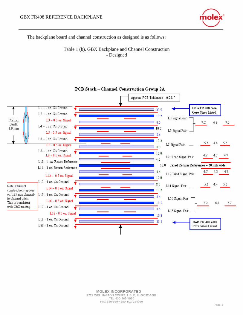
The backplane board and channel construction as designed is as follows:
Table 1 (b). GBX Backplane and Channel Construction - Designed

GBX FR408 REFERENCE BACKPLANE
MOLEX INCORPORATED 2222 WELLINGTON COURT, LISLE, IL 60532-1682
TEL 630-969-4550 FAX 630-969-4550 TLX 254069
Page 6
Notes:
1) Relative dielectric constant values are referenced at 2.5 GHz per Isola typical construction design guide. 2) Soldermask thickness is included in column 2 total thickness.

GBX FR408 REFERENCE BACKPLANE
MOLEX INCORPORATED 2222 WELLINGTON COURT, LISLE, IL 60532-1682
TEL 630-969-4550 FAX 630-969-4550 TLX 254069
Page 7
The following figures illustrate the construction of various channels:
8 mil TYP Prepreg
10.2 mil TYP Core
7.2 mil TYP Trace 6.8 mil
Channel Pitch
Progression = 1.85 mm
TYP
1.25 mil
0.6 mil
Core Dk = 3.57 Core Dissipation Factor = 0.013 Prepreg Dk = 3.43 Prepreg Dissipation Factor = 0.013 Channel Lengths = 44.21”, 34.37”, 25.00”, 20.00”, 15.00”, 10.00”, 3.00”
Fig 2. Distal Channel Construction, Style A (7.2/6.8/7.2) – loosely coupled.
GBX FR408 REFERENCE BACKPLANE
MOLEX INCORPORATED 2222 WELLINGTON COURT, LISLE, IL 60532-1682
TEL 630-969-4550 FAX 630-969-4550 TLX 254069
Page 8
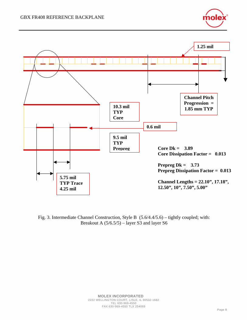
Core Dk = 3.89 Core Dissipation Factor = 0.013 Prepreg Dk = 3.73 Prepreg Dissipation Factor = 0.013 Channel Lengths = 22.10”, 17.18”, 12.50”, 10”, 7.50”, 5.00”
Fig. 3. Intermediate Channel Construction, Style B (5.6/4.4/5.6) – tightly coupled; with: Breakout A (5/6.5/5) – layer S3 and layer S6
9.5 mil TYP Prepreg
10.3 mil TYP Core
Channel Pitch Progression = 1.85 mm TYP
1.25 mil
0.6 mil
5.75 mil TYP Trace 4.25 mil

GBX FR408 REFERENCE BACKPLANE
MOLEX INCORPORATED 2222 WELLINGTON COURT, LISLE, IL 60532-1682
TEL 630-969-4550 FAX 630-969-4550 TLX 254069
Page 9
Core Dk = 3.8 Core Dissipation Factor = 0.013 Prepreg Dk = 3.67 Prepreg Dissipation Factor = 0.013 Channel Lengths = 22.10”, 17.18”, 12.50”, 10”, 7.50”, 5.00”
Fig. 4. Intermediate Channel Construction, Style C (4.7/4.3/4.7) – triad, loosely coupled; layers S4 & S5
1.25 mil
Channel Pitch
Progression = 1.85 mm
TYP
4.8 mil TYP Prepreg
12.5 mil TYP Core
5.5 mil TYP Trace 7.5 mil TYP Space
Signal Reference Width = 15 mils TYP
0.6 mil

GBX FR408 REFERENCE BACKPLANE
MOLEX INCORPORATED 2222 WELLINGTON COURT, LISLE, IL 60532-1682
TEL 630-969-4550 FAX 630-969-4550 TLX 254069
Page 10
Trace rout-outs and antipad constructions are depicted below:
Fig. 5. Standard data lines: flag routout, rectangular antipad,– layers S1, S2, S7, S8
Fig. 6. Clock line construction: Breakout A (5/6.5/5) – layer S3 and Layer S6
Rectangular antipad
Flag Routout
Hockey-Rink antipad
Flag Routout
GBX FR408 REFERENCE BACKPLANE
MOLEX INCORPORATED 2222 WELLINGTON COURT, LISLE, IL 60532-1682
TEL 630-969-4550 FAX 630-969-4550 TLX 254069
Page 11
Clock line channel construction is discussed in detail in Section 9.
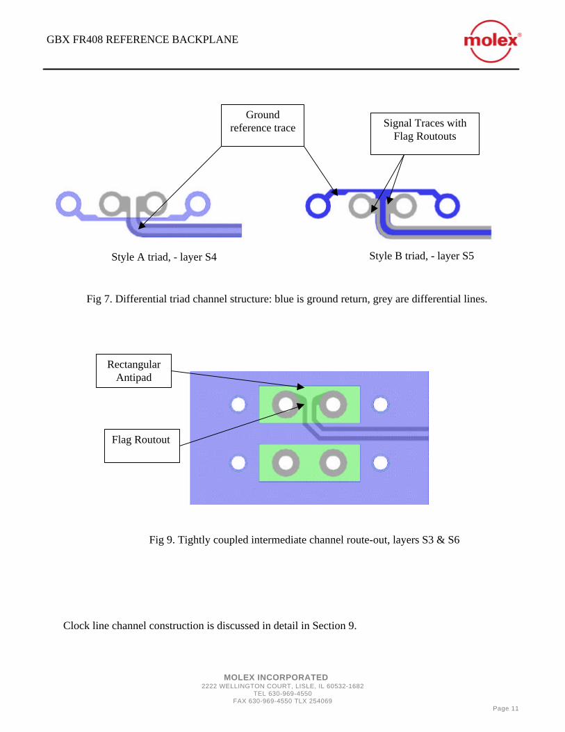
Style A triad, - layer S4
Style B triad, - layer S5
Fig 7. Differential triad channel structure: blue is ground return, grey are differential lines.
Fig 9. Tightly coupled intermediate channel route-out, layers S3 & S6
Ground reference trace Signal Traces with
Flag Routouts
Rectangular Antipad
Flag Routout

GBX FR408 REFERENCE BACKPLANE
MOLEX INCORPORATED 2222 WELLINGTON COURT, LISLE, IL 60532-1682
TEL 630-969-4550 FAX 630-969-4550 TLX 254069
Page 12
The design guide for active daughter-cards for using with the GBX reference Backplane is given below. Following this universal layout schedule will allow different silicon vendors perform interoperability testing across the backplane.
RX0
RX1
RX2
RX3
P
P
P
P
TX0
TX1
TX2
TX3
P
P
P
P
GbXTM Terminal Positions Designated By Flags For Each Backplane Connector
K2
K5
K4
K3
J5
J4
J3
J2
H5
H4
H3
H2
G5
G4
G3
G2
Connector Connector
Notes: • Both Outbound And Inbound Signal Sets Follow The Same Hook-up Schedule. • Transmitter And Receiver Polarity Is
Indicated (P: positive, N: negative).
N
N
N
N
N
N
N
N

GBX FR408 REFERENCE BACKPLANE
MOLEX INCORPORATED 2222 WELLINGTON COURT, LISLE, IL 60532-1682
TEL 630-969-4550 FAX 630-969-4550 TLX 254069
Page 13
2) 8-Inch Channel The connectors labeled J1 and J2 represent the 8-inch channel group. The outbound (TX) channels (as in Fig. 5) are on layer 3 (S1), where the thru-hole is optimized with backdrill of 15 mil below layer 6. The inbound (RX) channels are on layer 18 (S8). The TX and RX pin map is as follows: The typical channel schematic on the backplane is shown on Fig. 9. Outbound traffic is defined at TX channels traveling from left to right, while inbound traffic is TX channels traveling from right to left.
TX RX J2/K2 G2/H2 J3K3 G3/H3 J4/K4 G4/H4 J5/K5 G5/H5
Transmit –to-Receive Pin Map
Fig 9. Typical channel schematic: left-to right – outbound traffic; right-to-left – inbound traffic

GBX FR408 REFERENCE BACKPLANE
MOLEX INCORPORATED 2222 WELLINGTON COURT, LISLE, IL 60532-1682
TEL 630-969-4550 FAX 630-969-4550 TLX 254069
Page 14
* BD – backdrill 29 mil diameter
Clock Lines are designed as in Fig. 6 and Table 2, and are described in detail in Section 9.
Pair Layer Channel Construction Stub Length (mils) J2/K2 3 (S1) Channel A 35.3 (BD) (0.9 mm) J3/K3 3(S1) Channel A 35.3 (BD) (0.9 mm) J4/K4 3(S1) Channel A 35.3 (BD) (0.9 mm) J5/K5 3(S1) Channel A 35.3 (BD) (0.9 mm) G2/H2 3 (S1) Channel A 35.3 (BD) (0.9 mm) G3/H3 3(S1) Channel A 35.3 (BD) (0.9 mm) G4/H4 3(S1) Channel A 35.3 (BD) (0.9 mm) G5/H5 3(S1) Channel A 35.3 (BD) (0.9 mm)
Pair Layer Channel Construction Stub Length (mils) J2/K2 18(S8) Channel A 34 (0.863 mm) J3/K3 18(S8) Channel A 34 (0.863 mm) J4/K4 18(S8) Channel A 34 (0.863 mm) J5/K5 18(S8) Channel A 34 (0.863 mm) G2/H2 18(S8) Channel A 34 (0.863 mm) G3/H3 18(S8) Channel A 34 (0.863 mm) G4/H4 18(S8) Channel A 34 (0.863 mm) G5/H5 18(S8) Channel A 34 (0.863 mm)
Channel mapping and construction (length - 8” nom)
Outbound traffic
Inbound traffic

GBX FR408 REFERENCE BACKPLANE
MOLEX INCORPORATED 2222 WELLINGTON COURT, LISLE, IL 60532-1682
TEL 630-969-4550 FAX 630-969-4550 TLX 254069
Page 15
3) 15-Inch Channel The connectors labeled J3, J4, J73 and J74 represent the 15-inch channel group. The connectors J3 and J4 are the outer distal lanes, while J73 and J74 are the pass-thru traffic lanes. On the distal lane, outbound (TX) channels (as in Fig. 5) are on layer 3 (S1), with worst-case stub. The inbound (RX) channels are on layer 18 (S8). The TX and RX pin map is as follows: 3 a) Distal Channels
Clock Lines are designed as in Fig. 6 and Table 2, and are described in detail in Section 9.
TX RX J2/K2 G2/H2 J3K3 G3/H3 J4/K4 G4/H4 J5/K5 G5/H5
Pair Layer Channel Construction Stub Length (mils) J2/K2 3 (S1) Channel A 185.3 (4.7 mm) J3/K3 3(S1) Channel A 185.3 (4.7 mm) J4/K4 3(S1) Channel A 185.3 (4.7 mm) J5/K5 3(S1) Channel A 185.3 (4.7 mm) G2/H2 3 (S1) Channel A 185.3 (4.7 mm) G3/H3 3(S1) Channel A 185.3 (4.7 mm) G4/H4 3(S1) Channel A 185.3 (4.7 mm) G5/H5 3(S1) Channel A 185.3 (4.7 mm)
Pair Layer Channel Construction Stub Length (mils) J2/K2 18(S8) Channel A 34 (0.863 mm) J3/K3 18(S8) Channel A 34 (0.863 mm) J4/K4 18(S8) Channel A 34 (0.863 mm) J5/K5 18(S8) Channel A 34 (0.863 mm) G2/H2 18(S8) Channel A 34 (0.863 mm) G3/H3 18(S8) Channel A 34 (0.863 mm) G4/H4 18(S8) Channel A 34 (0.863 mm) G5/H5 18(S8) Channel A 34 (0.863 mm)
Transmit –to-Receive Pin Map
Channel mapping and construction (length – 15” nom)
Outbound traffic
Inbound traffic
Outbound/Inbound

GBX FR408 REFERENCE BACKPLANE
MOLEX INCORPORATED 2222 WELLINGTON COURT, LISLE, IL 60532-1682
TEL 630-969-4550 FAX 630-969-4550 TLX 254069
Page 16
3 b) 10-Inch Intermediate Channels On the pass-thru traffic lane, the channel design is a differential triad as in Fig. 7. The left-hand pattern (J73) has TX channels on layer 12 (S5) with worst-case via stub and triad construction of Style A (Fig. 7). The right-hand pattern has TX channels on layer 9 (S4) with via optimized by backdrill of 15 mil below layer 9, and triad construction of style B (Fig. 7). There are no clock lines on pass-thru lanes.
Pair Layer Channel Construction Stub Length (mils) J2/K2 9 (S4) Triad B 11.9 (BD) (0.3 mm) J3/K3 9(S4) Triad B 11.9 (BD) (0.3 mm) J4/K4 9(S4) Triad B 11.9 (BD) (0.3 mm) J5/K5 9(S4) Triad B 11.9 (BD) (0.3 mm) G2/H2 9(S4) Triad B 11.9 (BD) (0.3 mm) G3/H3 9(S4) Triad B 11.9 (BD) (0.3 mm) G4/H4 9(S4) Triad B 11.9 (BD) (0.3 mm) G5/H5 9(S4) Triad B 11.9 (BD) (0.3 mm)
Pair Layer Channel Construction Stub Length (mils) J2/K2 12(S5) Triad A 96.4 (2.45 mm) J3/K3 12(S5) Triad A 96.4 (2.45 mm) J4/K4 12(S5) Triad A 96.4 (2.45 mm) J5/K5 12(S5) Triad A 96.4 (2.45 mm) G2/H2 12(S5) Triad A 96.4 (2.45 mm) G3/H3 12(S5) Triad A 96.4 (2.45 mm) G4/H4 12(S5) Triad A 96.4 (2.45 mm) G5/H5 12(S5) Triad A 96.4 (2.45 mm)
Channel mapping and construction (length – 10” nom)
Outbound traffic
Inbound traffic

GBX FR408 REFERENCE BACKPLANE
MOLEX INCORPORATED 2222 WELLINGTON COURT, LISLE, IL 60532-1682
TEL 630-969-4550 FAX 630-969-4550 TLX 254069
Page 17
4) 20-Inch Channel The connectors labeled J5, J6, J75 and J76 represent the 20-inch channel group. The connectors J6 and J5 are the outer distal lanes, while J75 and J76 are the intermediate pass-thru traffic lanes. On the distal lane, outbound (TX) channels (as in Fig. 5) are on layer 5 (S2), where the thru-hole is optimized with backdrill of 15 mil below layer 6. The inbound (RX) channels are on layer 16 (S7), where the thru-hole is optimized with backdrill of 15 mil below layer 16. The TX and RX pin map is as follows: 4 a) Distal Channels
Clock Lines are designed as in Fig. 6 and Table 2, and are described in detail in Section 9.
TX RX J2/K2 G2/H2 J3K3 G3/H3 J4/K4 G4/H4 J5/K5 G5/H5
Pair Layer Channel Construction Stub Length (mils) J2/K2 5(S2) Channel A 14.8 (BD) (0.38 mm) J3/K3 5(S2) Channel A 14.8 (BD) (0.38 mm) J4/K4 5(S2) Channel A 14.8 (BD) (0.38 mm) J5/K5 5(S2) Channel A 14.8 (BD) (0.38 mm) G2/H2 5(S2) Channel A 14.8 (BD) (0.38 mm) G3/H3 5(S2) Channel A 14.8 (BD) (0.38 mm) G4/H4 5(S2) Channel A 14.8 (BD) (0.38 mm) G5/H5 5(S2) Channel A 14.8 (BD) (0.38 mm)
Pair Layer Channel Construction Stub Length (mils) J2/K2 16(S7) Channel A 15.6 (BD) (0.40 mm) J3/K3 16(S7) Channel A 15.6 (BD) (0.40 mm) J4/K4 16(S7) Channel A 15.6 (BD) (0.40 mm) J5/K5 16(S7) Channel A 15.6 (BD) (0.40 mm) G2/H2 16(S7) Channel A 15.6 (BD) (0.40 mm) G3/H3 16(S7) Channel A 15.6 (BD) (0.40 mm) G4/H4 16(S7) Channel A 15.6 (BD) (0.40 mm) G5/H5 16(S7) Channel A 15.6 (BD) (0.40 mm)
Transmit –to-Receive Pin Map
Channel mapping and construction (length – 20” nom)
Outbound traffic
Inbound traffic
Outbound/Inbound

GBX FR408 REFERENCE BACKPLANE
MOLEX INCORPORATED 2222 WELLINGTON COURT, LISLE, IL 60532-1682
TEL 630-969-4550 FAX 630-969-4550 TLX 254069
Page 18
4 b) 13-Inch Intermediate Channels On the pass-thru traffic lane, the channel design is a differential triad as in Fig. 7. The right-hand pattern (J76) has TX channels on layer 14 (S6) with a standard-design lower 5.75/4.25/5.75 pair and with via optimized by backdrill of 15 mil below layer 14. The left-hand pattern (J76)has TX channels on layer 9 (S4) with via optimized by backdrill of 15 mil below layer 9, and triad construction of style B (Fig. 7). There are no clock lines on pass-thru lanes.
Pair Layer Channel Construction Stub Length (mils) J2/K2 14(S6) Channel B, breakout A 15.6 (BD) (0.40 mm) J3/K3 14(S6) Channel B, breakout A 15.6 (BD) (0.40 mm) J4/K4 14(S6) Channel B, breakout A 15.6 (BD) (0.40 mm) J5/K5 14(S6) Channel B, breakout A 15.6 (BD) (0.40 mm) G2/H2 14(S6) Channel B, breakout A 15.6 (BD) (0.40 mm) G3/H3 14(S6) Channel B, breakout A 15.6 (BD) (0.40 mm) G4/H4 14(S6) Channel B, breakout A 15.6 (BD) (0.40 mm) G5/H5 14(S6) Channel B, breakout A 15.6 (BD) (0.40 mm)
Pair Layer Channel Construction Stub Length (mils) J2/K2 9 (S4) Triad B 11.9 (BD) (0.3 mm) J3/K3 9 (S4) Triad B 11.9 (BD) (0.3 mm) J4/K4 9 (S4) Triad B 11.9 (BD) (0.3 mm) J5/K5 9 (S4) Triad B 11.9 (BD) (0.3 mm) G2/H2 9 (S4) Triad B 11.9 (BD) (0.3 mm) G3/H3 9 (S4) Triad B 11.9 (BD) (0.3 mm) G4/H4 9 (S4) Triad B 11.9 (BD) (0.3 mm) G5/H5 9 (S4) Triad B 11.9 (BD) (0.3 mm)
Channel mapping and construction (length – 13” nom)
Outbound Traffic
Inbound Traffic

GBX FR408 REFERENCE BACKPLANE
MOLEX INCORPORATED 2222 WELLINGTON COURT, LISLE, IL 60532-1682
TEL 630-969-4550 FAX 630-969-4550 TLX 254069
Page 19
5) 25-Inch Channel The connectors labeled J7, J8, J19 and J20 represent the 25-inch channel group. The connectors J7 and J8 are the outer distal lanes, while J19 and J20 are the intermediate pass-thru traffic lanes. On the distal lane, outbound (TX) channels (as in Fig. 5) are on layer 3 (S1), where the thru-hole is optimized with backdrill of 15 mil below layer 6. The inbound (RX) channels are on layer 5 (S2), with worst-case via stub. The TX and RX pin map is as follows: 5 a) Distal Channels
Clock Lines are designed as in Fig. 6 and Table 2, and are described in detail in Section 9.
TX RX J2/K2 G2/H2 J3K3 G3/H3 J4/K4 G4/H4 J5/K5 G5/H5
Pair Layer Channel Construction Stub Length (mils) J2/K2 3(S1) Channel A 35.3 (BD) (0.9 mm) J3/K3 3(S1) Channel A 35.3 (BD) (0.9 mm) J4/K4 3(S1) Channel A 35.3 (BD) (0.9 mm) J5/K5 3(S1) Channel A 35.3 (BD) (0.9 mm) G2/H2 3(S1) Channel A 35.3 (BD) (0.9 mm) G3/H3 3(S1) Channel A 35.3 (BD) (0.9 mm) G4/H4 3(S1) Channel A 35.3 (BD) (0.9 mm) G5/H5 3(S1) Channel A 35.3 (BD) (0.9 mm)
Pair Layer Channel Construction Stub Length (mils) J2/K2 5(S2) Channel A 164.8 (4.19 mm) J3/K3 5(S2) Channel A 164.8 (4.19 mm) J4/K4 5(S2) Channel A 164.8 (4.19 mm) J5/K5 5(S2) Channel A 164.8 (4.19 mm) G2/H2 5(S2) Channel A 164.8 (4.19 mm) G3/H3 5(S2) Channel A 164.8 (4.19 mm) G4/H4 5(S2) Channel A 164.8 (4.19 mm) G5/H5 5(S2) Channel A 164.8 (4.19 mm)
Transmit –to-Receive Pin Map
Channel mapping and construction (length – 25” nom)
Outbound traffic
Inbound traffic
Outbound/Inbound

GBX FR408 REFERENCE BACKPLANE
MOLEX INCORPORATED 2222 WELLINGTON COURT, LISLE, IL 60532-1682
TEL 630-969-4550 FAX 630-969-4550 TLX 254069
Page 20
5 b) 15.5-Inch Intermediate Channels On the pass-thru traffic lane, the channel design is a differential triad as in Fig. 7. The left-hand pattern (J19) has TX channels on layer 7 (S3) with a standard-design lower 5.75/4.25/5.75 pair and with via optimized by backdrill of 15 mil below layer 7. The right-hand pattern (J76) has TX channels on layer 9 (S4) with worst-case via stub, and triad construction of style B (Fig. 7). There are no clock lines on pass-thru lanes.
Pair Layer Channel Construction Stub Length (mils) J2/K2 7(S3) Channel B, breakout A 17 (BD) (0.43 mm) J3/K3 7(S3) Channel B, breakout A 17 (BD) (0.43 mm) J4/K4 7(S3) Channel B, breakout A 17 (BD) (0.43 mm) J5/K5 7(S3) Channel B, breakout A 17 (BD) (0.43 mm) G2/H2 7(S3) Channel B, breakout A 17 (BD) (0.43 mm) G3/H3 7(S3) Channel B, breakout A 17 (BD) (0.43 mm) G4/H4 7(S3) Channel B, breakout A 17 (BD) (0.43 mm) G5/H5 7(S3) Channel B, breakout A 17 (BD) (0.43 mm)
Pair Layer Channel Construction Stub Length (mils) J2/K2 9 (S4) Triad B 120.8 (3.06 mm) J3/K3 9 (S4) Triad B 120.8 (3.06 mm) J4/K4 9 (S4) Triad B 120.8 (3.06 mm) J5/K5 9 (S4) Triad B 120.8 (3.06 mm) G2/H2 9 (S4) Triad B 120.8 (3.06 mm) G3/H3 9 (S4) Triad B 120.8 (3.06 mm) G4/H4 9 (S4) Triad B 120.8 (3.06 mm) G5/H5 9 (S4) Triad B 120.8 (3.06 mm)
Channel mapping and construction (length – 15.5” nom)
Outbound traffic
Inbound traffic

GBX FR408 REFERENCE BACKPLANE
MOLEX INCORPORATED 2222 WELLINGTON COURT, LISLE, IL 60532-1682
TEL 630-969-4550 FAX 630-969-4550 TLX 254069
Page 21
6) 30-Inch Channel The connectors labeled J9, J10, J17 and J18 represent the 20-inch channel group. The connectors J9 and J10 are the outer distal lanes, while J17 and J18 are the pass-thru traffic lanes. On the distal lane, outbound (TX) channels (as in Fig. 5) are on layer 5 (S2), where the thru-hole is optimized with backdrill of 15 mil below layer 6. The inbound (RX) channels are on layer 16 (S7), where the thru-hole is optimized with backdrill of 15 mil below layer 16. The TX and RX pin map is as follows: 6 a) Distal Channels
Clock Lines are designed as in Fig. 6 and Table 2, and are described in detail in Section 9.
TX RX J2/K2 G2/H2 J3K3 G3/H3 J4/K4 G4/H4 J5/K5 G5/H5
Pair Layer Channel Construction Stub Length (mils) J2/K2 5(S2) Channel A 14.8 (BD) (0.38 mm) J3/K3 5(S2) Channel A 14.8 (BD) (0.38 mm) J4/K4 5(S2) Channel A 14.8 (BD) (0.38 mm) J5/K5 5(S2) Channel A 14.8 (BD) (0.38 mm) G2/H2 5(S2) Channel A 14.8 (BD) (0.38 mm) G3/H3 5(S2) Channel A 14.8 (BD) (0.38 mm) G4/H4 5(S2) Channel A 14.8 (BD) (0.38 mm) G5/H5 5(S2) Channel A 14.8 (BD) (0.38 mm)
Pair Layer Channel Construction Stub Length (mils) J2/K2 16(S7) Channel A 15.6 (BD) (0.40 mm) J3/K3 16(S7) Channel A 15.6 (BD) (0.40 mm) J4/K4 16(S7) Channel A 15.6 (BD) (0.40 mm) J5/K5 16(S7) Channel A 15.6 (BD) (0.40 mm) G2/H2 16(S7) Channel A 15.6 (BD) (0.40 mm) G3/H3 16(S7) Channel A 15.6 (BD) (0.40 mm) G4/H4 16(S7) Channel A 15.6 (BD) (0.40 mm) G5/H5 16(S7) Channel A 15.6 (BD) (0.40 mm)
Transmit –to-Receive Pin Map
Channel mapping and construction (length – 30” nom)
Outbound traffic
Inbound traffic
Outbound/Inbound

GBX FR408 REFERENCE BACKPLANE
MOLEX INCORPORATED 2222 WELLINGTON COURT, LISLE, IL 60532-1682
TEL 630-969-4550 FAX 630-969-4550 TLX 254069
Page 22
6 b) 18-Inch Intermediate Channels On the pass-thru traffic lane, the channel design is a differential triad as in Fig. 7. The right-hand pattern (J18) has TX channels on layer 14 (S6) with a standard-design lower 5.75/4.25/5.75 pair and with via optimized by backdrill of 15 mil below layer 14. The left-hand pattern (J17)has TX channels on layer 9 (S4) with via optimized by backdrill of 15 mil below layer 9, and triad construction of style B (Fig. 7). There are no clock lines on pass-thru lanes.
Pair Layer Channel Construction Stub Length (mils) J2/K2 14(S6) Channel B, breakout A 15.6 (BD) (0.40 mm) J3/K3 14(S6) Channel B, breakout A 15.6 (BD) (0.40 mm) J4/K4 14(S6) Channel B, breakout A 15.6 (BD) (0.40 mm) J5/K5 14(S6) Channel B, breakout A 15.6 (BD) (0.40 mm) G2/H2 14(S6) Channel B, breakout A 15.6 (BD) (0.40 mm) G3/H3 14(S6) Channel B, breakout A 15.6 (BD) (0.40 mm) G4/H4 14(S6) Channel B, breakout A 15.6 (BD) (0.40 mm) G5/H5 14(S6) Channel B, breakout A 15.6 (BD) (0.40 mm)
Pair Layer Channel Construction Stub Length (mils) J2/K2 9 (S4) Triad B 11.9 (BD) (0.3 mm) J3/K3 9 (S4) Triad B 11.9 (BD) (0.3 mm) J4/K4 9 (S4) Triad B 11.9 (BD) (0.3 mm) J5/K5 9 (S4) Triad B 11.9 (BD) (0.3 mm) G2/H2 9 (S4) Triad B 11.9 (BD) (0.3 mm) G3/H3 9 (S4) Triad B 11.9 (BD) (0.3 mm) G4/H4 9 (S4) Triad B 11.9 (BD) (0.3 mm) G5/H5 9 (S4) Triad B 11.9 (BD) (0.3 mm)
Channel mapping and construction (length – 18” nom)
Outbound traffic
Inbound traffic

GBX FR408 REFERENCE BACKPLANE
MOLEX INCORPORATED 2222 WELLINGTON COURT, LISLE, IL 60532-1682
TEL 630-969-4550 FAX 630-969-4550 TLX 254069
Page 23
7) 1-Meter Channel The connectors labeled J11, J12, J15 and J16 represent the 1-meter channel group. The connectors J11 and J12 are the outer distal lanes, while J15 and J16 are the pass-thru traffic lanes. On the distal lanes, outbound (TX) channels (as in Fig. 5) are on layer 18 (S8), where the thru-hole is not optimized with backdrill. The inbound (RX) channels are on layer 3 (S1), with backdrill of 15 mil below layer 6. The TX and RX pin map is as follows: 7 a) Distal Channels
Clock Lines are designed as in Fig. 6, and are mapped as in Table 2.
TX RX J2/K2 G2/H2 J3K3 G3/H3 J4/K4 G4/H4 J5/K5 G5/H5
Pair Layer Channel Construction Stub Length (mils) J2/K2 3 (S1) Channel A 35.3 (BD) (0.9 mm) J3/K3 3 (S1) Channel A 35.3 (BD) (0.9 mm) J4/K4 3 (S1) Channel A 35.3 (BD) (0.9 mm) J5/K5 3 (S1) Channel A 35.3 (BD) (0.9 mm) G2/H2 3 (S1) Channel A 35.3 (BD) (0.9 mm) G3/H3 3 (S1) Channel A 35.3 (BD) (0.9 mm) G4/H4 3 (S1) Channel A 35.3 (BD) (0.9 mm) G5/H5 3 (S1) Channel A 35.3 (BD) (0.9 mm)
Pair Layer Channel Construction Stub Length (mils) J2/K2 18(S8) Channel A 34 (0.863 mm) J3/K3 18(S8) Channel A 34 (0.863 mm) J4/K4 18(S8) Channel A 34 (0.863 mm) J5/K5 18(S8) Channel A 34 (0.863 mm) G2/H2 18(S8) Channel A 34 (0.863 mm) G3/H3 18(S8) Channel A 34 (0.863 mm) G4/H4 18(S8) Channel A 34 (0.863 mm) G5/H5 18(S8) Channel A 34 (0.863 mm)
Transmit –to-Receive Pin Map
Channel mapping and construction (length – 39.37” nom)
Outbound traffic
Inbound traffic
Outbound/Inbound

GBX FR408 REFERENCE BACKPLANE
MOLEX INCORPORATED 2222 WELLINGTON COURT, LISLE, IL 60532-1682
TEL 630-969-4550 FAX 630-969-4550 TLX 254069
Page 24
7 b) 20-Inch Intermediate Channels On the pass-thru traffic lane, the channel design is a differential triad as in Fig. 7. The right-hand pattern (J16) has TX channels on layer 7 (S3) with a standard-design lower 5.75/4.25/5.75 pair and worst-case via stub. The left-hand pattern (J15) has TX channels on layer 12 (S5) with worst-case via stub, and triad construction of style B (Fig. 7). There are no clock lines on pass-thru lanes.
Pair Layer Channel Construction Stub Length (mils) J2/K2 12(S5) Triad B 96.4 (2.45 mm) J3/K3 12(S5) Triad B 96.4 (2.45 mm) J4/K4 12(S5) Triad B 96.4 (2.45 mm) J5/K5 12(S5) Triad B 96.4 (2.45 mm) G2/H2 12(S5) Triad B 96.4 (2.45 mm) G3/H3 12(S5) Triad B 96.4 (2.45 mm) G4/H4 12(S5) Triad B 96.4 (2.45 mm) G5/H5 12(S5) Triad B 96.4 (2.45 mm)
Pair Layer Channel Construction Stub Length (mils) J2/K2 7(S3) Channel B, breakout A 144.4 (3.67 mm) J3/K3 7(S3) Channel B, breakout A 144.4 (3.67 mm) J4/K4 7(S3) Channel B, breakout A 144.4 (3.67 mm) J5/K5 7(S3) Channel B, breakout A 144.4 (3.67 mm) G2/H2 7(S3) Channel B, breakout A 144.4 (3.67 mm) G3/H3 7(S3) Channel B, breakout A 144.4 (3.67 mm) G4/H4 7(S3) Channel B, breakout A 144.4 (3.67 mm) G5/H5 7(S3) Channel B, breakout A 144.4 (3.67 mm)
Channel mapping and construction (length – 20” nom)
Outbound traffic
Inbound traffic
GBX FR408 REFERENCE BACKPLANE
MOLEX INCORPORATED 2222 WELLINGTON COURT, LISLE, IL 60532-1682
TEL 630-969-4550 FAX 630-969-4550 TLX 254069
Page 25
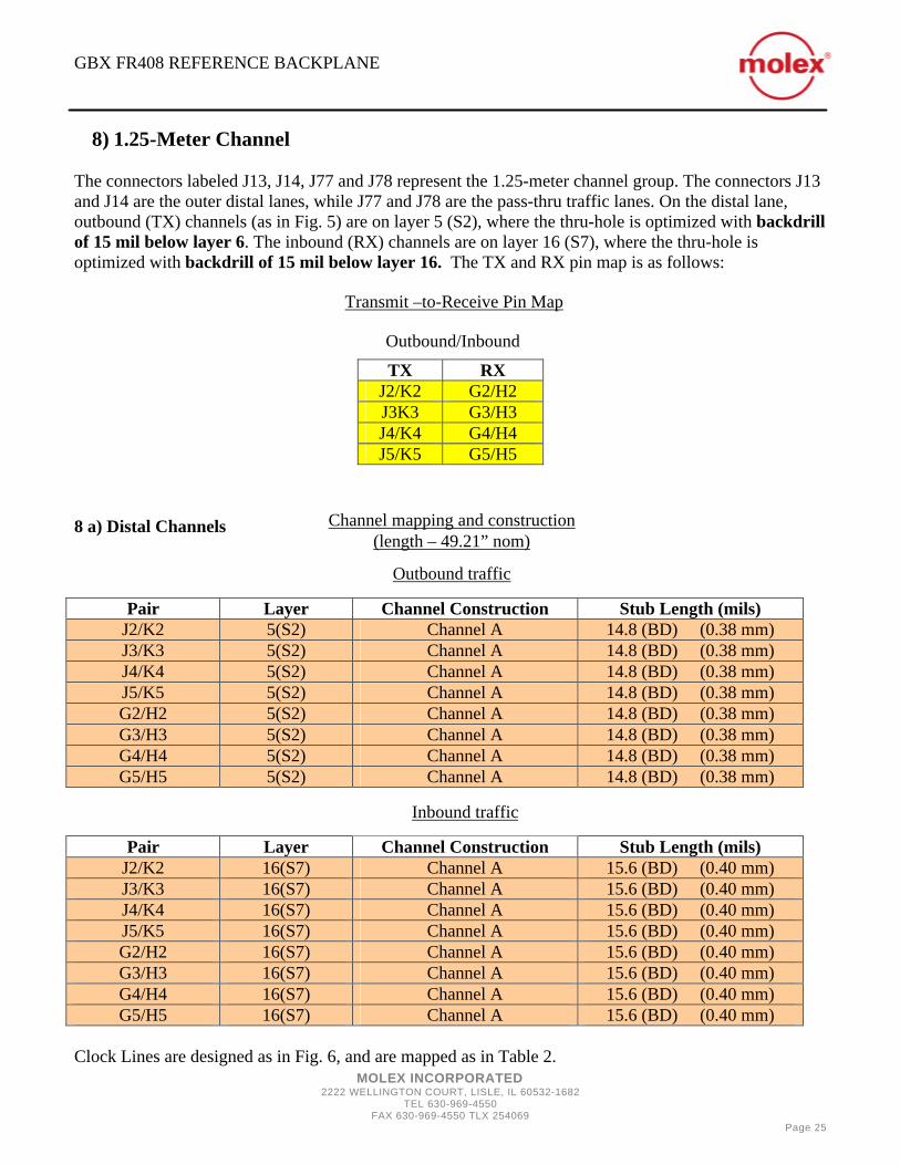
8) 1.25-Meter Channel The connectors labeled J13, J14, J77 and J78 represent the 1.25-meter channel group. The connectors J13 and J14 are the outer distal lanes, while J77 and J78 are the pass-thru traffic lanes. On the distal lane, outbound (TX) channels (as in Fig. 5) are on layer 5 (S2), where the thru-hole is optimized with backdrill of 15 mil below layer 6. The inbound (RX) channels are on layer 16 (S7), where the thru-hole is optimized with backdrill of 15 mil below layer 16. The TX and RX pin map is as follows:
8 a) Distal Channels
Clock Lines are designed as in Fig. 6, and are mapped as in Table 2.
TX RX J2/K2 G2/H2 J3K3 G3/H3 J4/K4 G4/H4 J5/K5 G5/H5
Pair Layer Channel Construction Stub Length (mils) J2/K2 5(S2) Channel A 14.8 (BD) (0.38 mm) J3/K3 5(S2) Channel A 14.8 (BD) (0.38 mm) J4/K4 5(S2) Channel A 14.8 (BD) (0.38 mm) J5/K5 5(S2) Channel A 14.8 (BD) (0.38 mm) G2/H2 5(S2) Channel A 14.8 (BD) (0.38 mm) G3/H3 5(S2) Channel A 14.8 (BD) (0.38 mm) G4/H4 5(S2) Channel A 14.8 (BD) (0.38 mm) G5/H5 5(S2) Channel A 14.8 (BD) (0.38 mm)
Pair Layer Channel Construction Stub Length (mils) J2/K2 16(S7) Channel A 15.6 (BD) (0.40 mm) J3/K3 16(S7) Channel A 15.6 (BD) (0.40 mm) J4/K4 16(S7) Channel A 15.6 (BD) (0.40 mm) J5/K5 16(S7) Channel A 15.6 (BD) (0.40 mm) G2/H2 16(S7) Channel A 15.6 (BD) (0.40 mm) G3/H3 16(S7) Channel A 15.6 (BD) (0.40 mm) G4/H4 16(S7) Channel A 15.6 (BD) (0.40 mm) G5/H5 16(S7) Channel A 15.6 (BD) (0.40 mm)
Transmit –to-Receive Pin Map
Channel mapping and construction (length – 49.21” nom)
Outbound traffic
Inbound traffic
Outbound/Inbound

GBX FR408 REFERENCE BACKPLANE
MOLEX INCORPORATED 2222 WELLINGTON COURT, LISLE, IL 60532-1682
TEL 630-969-4550 FAX 630-969-4550 TLX 254069
Page 26
8 b) 27-Inch Intermediate Channels On the pass-thru traffic lane, the channel design is a differential triad as in Fig. 7. The left-hand pattern (J77) has TX channels on layer 12 (S5) with via optimized by backdrill of 15 mil below layer 12 and triad construction of Style A (Fig. 7). The right-hand pattern has TX channels on layer 9 (S4) with via optimized by backdrill of 15 mil below layer 9, and triad construction of style B (Fig. 7). There are no clock lines on pass-thru lanes.
Pair Layer Channel Construction Stub Length (mils) J2/K2 12(S5) Triad A 18.1 (BD) (0.46 mm) J3/K3 12(S5) Triad A 18.1 (BD) (0.46 mm) J4/K4 12(S5) Triad A 18.1 (BD) (0.46 mm) J5/K5 12(S5) Triad A 18.1 (BD) (0.46 mm) G2/H2 12(S5) Triad A 18.1 (BD) (0.46 mm) G3/H3 12(S5) Triad A 18.1 (BD) (0.46 mm) G4/H4 12(S5) Triad A 18.1 (BD) (0.46 mm) G5/H5 12(S5) Triad A 18.1 (BD) (0.46 mm)
Pair Layer Channel Construction Stub Length (mils) J2/K2 9 (S4) Triad B 11.9 (BD) (0.3 mm) J3/K3 9(S4) Triad B 11.9 (BD) (0.3 mm) J4/K4 9(S4) Triad B 11.9 (BD) (0.3 mm) J5/K5 9(S4) Triad B 11.9 (BD) (0.3 mm) G2/H2 9 (S4) Triad B 11.9 (BD) (0.3 mm) G3/H3 9(S4) Triad B 11.9 (BD) (0.3 mm) G4/H4 9(S4) Triad B 11.9 (BD) (0.3 mm) G5/H5 9(S4) Triad B 11.9 (BD) (0.3 mm)
Channel mapping and construction (length – 27.1” nom)
Outbound traffic
Inbound traffic

GBX FR408 REFERENCE BACKPLANE
MOLEX INCORPORATED 2222 WELLINGTON COURT, LISLE, IL 60532-1682
TEL 630-969-4550 FAX 630-969-4550 TLX 254069
Page 27
9) Clock Lines In addition to standard data channels, all distal lanes also include clock lines designed with a large “hockey rink” antipad and a tapered breakout. (Fig 6). The outbound and inbound traffic channels are defined in the same way as above, left-to-right and right-to-left, respectively. The transmit and receive pin mapping is All (DE) clock lines are on signal layer S6 and the (AB) lines are on layer S3, as per Table 2. However, clock lines in different channel groups have different via stubs, some being optimized with a 29 mil-wide backdrill 15 mil below the respective layer. This is described in detail in the following subsections. 9 a) 8-Inch Channel
TX RX A7/B7 D7/E7 A8/B8 D8/E8
Pair Layer Channel Construction Stub length (mils) A8/B8 7(S3) Breakout A 17 (BD) (0.43 mm) A7/B7 7(S3) Breakout A 17 (BD) (0.43 mm) D8/E8 7(S3) Breakout A 17 (BD) (0.43 mm) D7/E7 7(S3) Breakout A 17 (BD) (0.43 mm)
Pair Layer Channel Construction Stub length (mils) A8/B8 14(S6) Breakout A 15.6 (BD) (0.40 mm) A7/B7 14(S6) Breakout A 15.6 (BD) (0.40 mm) D8/E8 14(S6) Breakout A 15.6 (BD) (0.40 mm) D7/E7 14(S6) Breakout A 15.6 (BD) (0.40 mm)
Transmit –to-Receive Pin Map
Channel mapping and construction (length - 8” nom)
Outbound traffic
Inbound traffic
Outbound/Inbound
GBX FR408 REFERENCE BACKPLANE
MOLEX INCORPORATED 2222 WELLINGTON COURT, LISLE, IL 60532-1682
TEL 630-969-4550 FAX 630-969-4550 TLX 254069
Page 28
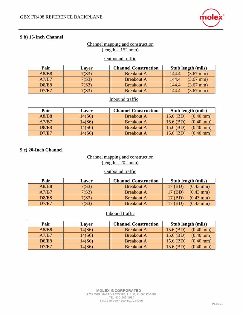
9 b) 15-Inch Channel
9 c) 20-Inch Channel
Pair Layer Channel Construction Stub length (mils) A8/B8 7(S3) Breakout A 144.4 (3.67 mm) A7/B7 7(S3) Breakout A 144.4 (3.67 mm) D8/E8 7(S3) Breakout A 144.4 (3.67 mm) D7/E7 7(S3) Breakout A 144.4 (3.67 mm)
Pair Layer Channel Construction Stub length (mils) A8/B8 14(S6) Breakout A 15.6 (BD) (0.40 mm) A7/B7 14(S6) Breakout A 15.6 (BD) (0.40 mm) D8/E8 14(S6) Breakout A 15.6 (BD) (0.40 mm) D7/E7 14(S6) Breakout A 15.6 (BD) (0.40 mm)
Pair Layer Channel Construction Stub length (mils) A8/B8 7(S3) Breakout A 17 (BD) (0.43 mm) A7/B7 7(S3) Breakout A 17 (BD) (0.43 mm) D8/E8 7(S3) Breakout A 17 (BD) (0.43 mm) D7/E7 7(S3) Breakout A 17 (BD) (0.43 mm)
Pair Layer Channel Construction Stub length (mils) A8/B8 14(S6) Breakout A 15.6 (BD) (0.40 mm) A7/B7 14(S6) Breakout A 15.6 (BD) (0.40 mm) D8/E8 14(S6) Breakout A 15.6 (BD) (0.40 mm) D7/E7 14(S6) Breakout A 15.6 (BD) (0.40 mm)
Channel mapping and construction (length - 15” nom)
Outbound traffic
Inbound traffic
Channel mapping and construction (length - 20” nom)
Outbound traffic
Inbound traffic
GBX FR408 REFERENCE BACKPLANE
MOLEX INCORPORATED 2222 WELLINGTON COURT, LISLE, IL 60532-1682
TEL 630-969-4550 FAX 630-969-4550 TLX 254069
Page 29
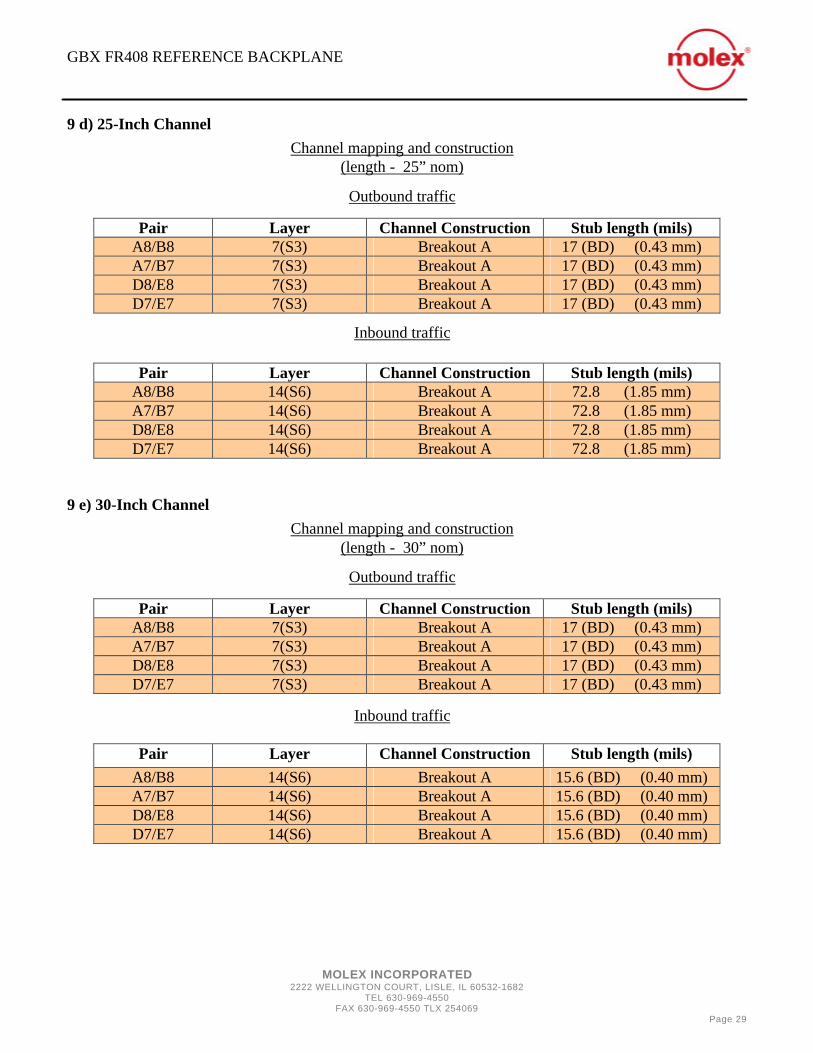
9 d) 25-Inch Channel
9 e) 30-Inch Channel
Pair Layer Channel Construction Stub length (mils) A8/B8 7(S3) Breakout A 17 (BD) (0.43 mm) A7/B7 7(S3) Breakout A 17 (BD) (0.43 mm) D8/E8 7(S3) Breakout A 17 (BD) (0.43 mm) D7/E7 7(S3) Breakout A 17 (BD) (0.43 mm)
Pair Layer Channel Construction Stub length (mils) A8/B8 14(S6) Breakout A 72.8 (1.85 mm) A7/B7 14(S6) Breakout A 72.8 (1.85 mm) D8/E8 14(S6) Breakout A 72.8 (1.85 mm) D7/E7 14(S6) Breakout A 72.8 (1.85 mm)
Pair Layer Channel Construction Stub length (mils) A8/B8 7(S3) Breakout A 17 (BD) (0.43 mm) A7/B7 7(S3) Breakout A 17 (BD) (0.43 mm) D8/E8 7(S3) Breakout A 17 (BD) (0.43 mm) D7/E7 7(S3) Breakout A 17 (BD) (0.43 mm)
Pair Layer Channel Construction Stub length (mils) A8/B8 14(S6) Breakout A 15.6 (BD) (0.40 mm) A7/B7 14(S6) Breakout A 15.6 (BD) (0.40 mm) D8/E8 14(S6) Breakout A 15.6 (BD) (0.40 mm) D7/E7 14(S6) Breakout A 15.6 (BD) (0.40 mm)
Channel mapping and construction (length - 25” nom)
Outbound traffic
Inbound traffic
Channel mapping and construction (length - 30” nom)
Outbound traffic
Inbound traffic

GBX FR408 REFERENCE BACKPLANE
MOLEX INCORPORATED 2222 WELLINGTON COURT, LISLE, IL 60532-1682
TEL 630-969-4550 FAX 630-969-4550 TLX 254069
Page 30
9 f) 1-Meter Channel
9 g) 1.25-Meter Channel
Pair Layer Channel Construction Stub length (mils) A8/B8 7(S3) Breakout A 144.4 (3.67 mm) A7/B7 7(S3) Breakout A 144.4 (3.67 mm) D8/E8 7(S3) Breakout A 144.4 (3.67 mm) D7/E7 7(S3) Breakout A 144.4 (3.67 mm)
Pair Layer Breakout Stub length (mils) A8/B8 14(S6) Breakout A 15.6 (BD) (0.40 mm) A7/B7 14(S6) Breakout A 15.6 (BD) (0.40 mm) D8/E8 14(S6) Breakout A 15.6 (BD) (0.40 mm) D7/E7 14(S6) Breakout A 15.6 (BD) (0.40 mm)
Pair Layer Channel Construction Stub length (mils) A8/B8 7(S3) Breakout A 17 (BD) (0.43 mm) A7/B7 7(S3) Breakout A 17 (BD) (0.43 mm) D8/E8 7(S3) Breakout A 17 (BD) (0.43 mm) D7/E7 7(S3) Breakout A 17 (BD) (0.43 mm)
Pair Layer Channel Construction Stub length (mils) A8/B8 14(S6) Breakout A 15.6 (BD) (0.40 mm) A7/B7 14(S6) Breakout A 15.6 (BD) (0.40 mm) D8/E8 14(S6) Breakout A 15.6 (BD) (0.40 mm) D7/E7 14(S6) Breakout A 15.6 (BD) (0.40 mm)
Channel mapping and construction (length - 39.37” nom)
Outbound traffic
Inbound traffic
Channel mapping and construction (length - 49.21” nom)
Outbound traffic
Inbound traffic

GBX FR408 REFERENCE BACKPLANE
MOLEX INCORPORATED 2222 WELLINGTON COURT, LISLE, IL 60532-1682
TEL 630-969-4550 FAX 630-969-4550 TLX 254069
Page 31
Appendix: Channel Grouping by Length
Layer Channel Construction
Stub Length (mils)
Location on PCB Length (inches)
3 (S1) Channel A 35.3 (BD) (0.9 mm)
8 inch distal, outbound; J2/K2, J3/K3, J4/K4, J5/K5
8
18(S8) Channel A 34 (0.863 mm)
8 inch distal, inbound; J2/K2, J3/K3, J4/K4, J5/K5
8
7(S3) Breakout A 17 (BD) (0.47 mm)
8 inch distal, clock lines, inbound, outbound, A7/B7,A8/B8
8
14(S6) Breakout A 15.6 (BD) (1.40 mm)
18 inch distal, clock lines, inbound, outbound; D7/E7, D8/E8
8
12(S5) Triad A 96.4 (2.45 mm)
15” pass-thru, outbound; J2/K2, J3/K3, J4/K4, J5/K5
10
9 (S4) Triad B 11.9 (BD) (0.3 mm)
15” pass-thru, inbound; J2/K2, J3/K3, J4/K4, J5/K5
10
Layer Channel Construction
Stub Length (mils)
Location on PCB Length (inches)
3 (S1) Channel A 185.3 (4.7 mm)
15 inch distal, outbound; J2/K2, J3/K3, J4/K4, J5/K5
15
18(S8) Channel A 34 (0.863 mm)
15 inch distal, inbound; J2/K2, J3/K3, J4/K4, J5/K5
15
7(S3) Breakout A 144.4 (3.67 mm)
15 inch distal, clock lines, outbound, A7/B7,A8/B8
15
14(S6) Breakout A 17 (BD) (0.47 mm)
15 inch distal, clock lines, outbound, D7/E7, D8/E8
15
7(S3) Breakout A 17 (BD) (0.47 mm)
15 inch distal, clock lines, inbound, A7/B7,A8/B8
15
14(S6) Breakout A 72.8 (1.85 mm)
15 inch distal, clock lines, inbound, D7/E7, D8/E8
15
14(S6) Channel B, breakout A
15.6 (BD) (1.40 mm)
20” pass-thru, outbound, J2/K2, J3/K3, J4/K4, J5/K5
13
9 (S4) Triad B 11.9 (BD) (0.3 mm)
20” pass-thru, inbound, J2/K2, J3/K3, J4/K4, J5/K5
13
7(S3) Channel B, breakout A
17 (BD) (0.47 mm)
25” pass-thru, outbound, J2/K2, J3/K3, J4/K4, J5/K5
15.5
9 (S4) Triad B 120.8 (3.06 mm)
25” pass-thru, inbound, J2/K2, J3/K3, J4/K4, J5/K5
15.5
8” – 10” length
13” – 15.5” length

GBX FR408 REFERENCE BACKPLANE
MOLEX INCORPORATED 2222 WELLINGTON COURT, LISLE, IL 60532-1682
TEL 630-969-4550 FAX 630-969-4550 TLX 254069
Page 32
Layer Channel Construction
Stub Length (mils)
Location on PCB Length (inches)
5(S2) Channel A 14.8 (BD) (1.38 mm)
20 inch distal, outbound; J2/K2, J3/K3, J4/K4, J5/K5
20
16(S7) Channel A 15.6 (BD) (1.40 mm)
20 inch distal, inbound; J2/K2, J3/K3, J4/K4, J5/K5
20
7(S3) Breakout A 17.3 (BD) (0.44 mm))
20 inch distal, clock lines, outbound, outbound; A7/B7,A8/B8
20
14(S6) Breakout A 15.6 (BD) (1.40 mm)
20 inch distal, clock lines, outbound, outbound; D7/E7, D8/E8
20
7(S3) Breakout A 15.6 (BD) (1.40 mm)
20 inch distal, clock lines, inbound, outbound; A7/B7,A8/B8
20
14(S6) Breakout A 17 (BD) (0.47 mm)
20 inch distal, clock lines, inbound, outbound; D7/E7, D8/E8
20
9 (S4) Triad B 11.9 (BD) (0.3 mm)
30” pass-thru, outbound, J2/K2, J3/K3, J4/K4, J5/K5
18
14(S6) Channel B Breakout A
15.6 (BD) (1.40 mm)
30” pass-thru, inbound, J2/K2, J3/K3, J4/K4, J5/K5
18
Layer Channel Construction
Stub Length (mils)
Location on PCB Length (inches)
3(S1) Channel A 35.3 (BD) (0.9 mm)
25 inch distal, outbound; J2/K2, J3/K3, J4/K4, J5/K5
25
5(S2) Channel A 164.8 (4.19 mm)
25 inch distal, inbound; J2/K2, J3/K3, J4/K4, J5/K5
25
7(S3) Breakout A 17 (BD) (0.47 mm)
25 inch distal, clock lines, outbound, A7/B7,A8/B8
25
14(S6) Breakout A 72.8 (1.85 mm)
25 inch distal, clock lines, outbound, D7/E7, D8/E8
25
7(S3) Breakout A 144.4 (3.7 mm)
25 inch distal, clock lines, inbound, A7/B7,A8/B8
25
14(S6) Breakout A 17 (BD) (0.47 mm)
25 inch distal, clock lines, inbound, D7/E7, D8/E8
25
12(S5) Triad A 18.1 (BD) (0.46 mm)
1.25 m pass-thru, outbound, J2/K2, J3/K3, J4/K4, J5/K5
27.1
9 (S4) Triad B 11.9 (BD) (0.3 mm)
1.25 m pass-thru, inbound, J2/K2, J3/K3, J4/K4, J5/K5
27.1
18” – 20” length
25” – 27” length
GBX FR408 REFERENCE BACKPLANE
MOLEX INCORPORATED 2222 WELLINGTON COURT, LISLE, IL 60532-1682
TEL 630-969-4550 FAX 630-969-4550 TLX 254069
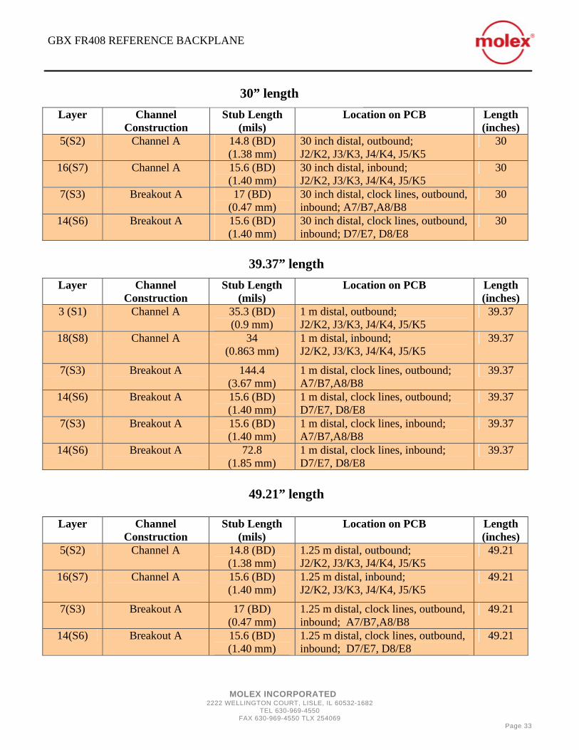
Page 33
Layer Channel Construction
Stub Length (mils)
Location on PCB Length (inches)
5(S2) Channel A 14.8 (BD) (1.38 mm)
30 inch distal, outbound; J2/K2, J3/K3, J4/K4, J5/K5
30
16(S7) Channel A 15.6 (BD) (1.40 mm)
30 inch distal, inbound; J2/K2, J3/K3, J4/K4, J5/K5
30
7(S3) Breakout A 17 (BD) (0.47 mm)
30 inch distal, clock lines, outbound, inbound; A7/B7,A8/B8
30
14(S6) Breakout A 15.6 (BD) (1.40 mm)
30 inch distal, clock lines, outbound, inbound; D7/E7, D8/E8
30
Layer Channel Construction
Stub Length (mils)
Location on PCB Length (inches)
3 (S1) Channel A 35.3 (BD) (0.9 mm)
1 m distal, outbound; J2/K2, J3/K3, J4/K4, J5/K5
39.37
18(S8) Channel A 34 (0.863 mm)
1 m distal, inbound; J2/K2, J3/K3, J4/K4, J5/K5
39.37
7(S3) Breakout A 144.4 (3.67 mm)
1 m distal, clock lines, outbound; A7/B7,A8/B8
39.37
14(S6) Breakout A 15.6 (BD) (1.40 mm)
1 m distal, clock lines, outbound; D7/E7, D8/E8
39.37
7(S3) Breakout A 15.6 (BD) (1.40 mm)
1 m distal, clock lines, inbound; A7/B7,A8/B8
39.37
14(S6) Breakout A 72.8 (1.85 mm)
1 m distal, clock lines, inbound; D7/E7, D8/E8
39.37
Layer Channel Construction
Stub Length (mils)
Location on PCB Length (inches)
5(S2) Channel A 14.8 (BD) (1.38 mm)
1.25 m distal, outbound; J2/K2, J3/K3, J4/K4, J5/K5
49.21
16(S7) Channel A 15.6 (BD) (1.40 mm)
1.25 m distal, inbound; J2/K2, J3/K3, J4/K4, J5/K5
49.21
7(S3) Breakout A 17 (BD) (0.47 mm)
1.25 m distal, clock lines, outbound, inbound; A7/B7,A8/B8
49.21
14(S6) Breakout A 15.6 (BD) (1.40 mm)
1.25 m distal, clock lines, outbound, inbound; D7/E7, D8/E8
49.21
30” length
39.37” length
49.21” length

GBX FR408 REFERENCE BACKPLANE
MOLEX INCORPORATED 2222 WELLINGTON COURT, LISLE, IL 60532-1682
TEL 630-969-4550 FAX 630-969-4550 TLX 254069
Page 34
RESOURCES For GBX products and information contact:
Gary A. Humbert Molex Inc.,
2222 Wellington Court Lisle IL 60532
Phone: 630-718-5830 Fax: 630-512-8620
e-mail: [email protected] For PMC – Sierra products and information contact:
Owen Williams PMC-Sierra Inc.
8555 Baxter Place Burnaby, BC V5A 4V7
Canada Phone: 604-415-6000 Fax: 604-415-6205
e-mail: [email protected]
Please note that patents have been applied for by Molex for: the Triad PCB routing scheme, the specific pinfield trace routing designs, and the anti-pad configurations described in this document.