gdansk stadium_2013.pdf
TRANSCRIPT
54 Steel Construction 6 (2013), No. 1
Reports
DOI: 10.1002/stco.201300001
The technology of assembling the roof over the stadium built in Gdansk for the EURO 2012 European Football Championship is discussed here. The stadium has a characteristic silhouette – its shape and the colours of the façade resemble a cut block of amber. The steel roof structure has a quasi-elliptical form, with a maximum diameter of 220 m and minimum diameter of 187 m. It is 38 m high and the roof girders extend 48 m over the grandstand below. The roof structure weights 7150 t and was assembled in 226 days.
1 Introduction
The most recent European Football Championship tourna-ment took place in June and July 2012. Poland and the Ukraine had been entrusted by UEFA with organizing that event. Each of the hosts was obliged to build four modern stadiums meeting UEFA’s standards. Warsaw, Gdansk, Poznan and Wrocław in Poland, and Kiev, Kharkiv, Donetsk and Lviv in Ukraine were the cities selected as host venues.
The stadium in Gdansk is designed for about 41 000 spectators. It is sited on a plot of 43 650 m2 located be-tween the old town and new port districts. A German archi-tectural practice, RKW Rhode, Kellermann, Wawrowsky GmbH from Düsseldorf, won the competition for the sta-dium design and subsequently prepared the architectural and conceptual designs. Detailed design work was awarded as follows:– Foundations – Prof. Dr. hab. Eng. Michał Topolnicki,
Gdansk University of Technology– Concrete for foundations and grandstands – Autorska
Pracownia Konstrukcyjna “Wojdak”, Dr. Eng. Ryszard Wojdak (design checked by Prof. Dr. hab. Eng. Tadeusz Godycki-Cwirko)
– Steel roof structure – Konsultacyjne Biuro Projektów Z.ółtowski, Dr. hab. Eng. Krzysztof Z
.ółtowski, professor,
Gdansk University of Technology, and his team– Steel structure assembly – Martfer Polska Sp. z o.o.– Grandstand structure components, landscape architec-
ture and coordination of all design work – Eilers & Vogel, Hannover
The construction work was carried out by the Hydrobudowa Polska/Alpine Polska Consortium.
The steel structure for the roof over the grandstand was fabricated and assembled by a consortium composed of:
– ENERGOMONTAZ. POŁUDNIE S.A., Katowice
– PBG – Technologia, Wysogotowo (near Poznan)– Martifer Polska Sp. z o.o., Gliwice– Ocekon Engineering, Kosice (Slovakia)
Eng. Tomasz Osubniak, MSc (Martifer Polska Sp. z o.o.) was the construction manager for the stadium roof and Eng. Tomasz Zyska, MSc (ENERGOMONTAZ
. POŁUDNIE
S.A.) was responsible for the final stage of the construction work and dismantling of the supporting lattice beams and erection towers as well as lowering the roof from an auxil-iary structure.
2 General characteristics of stadium roof structure
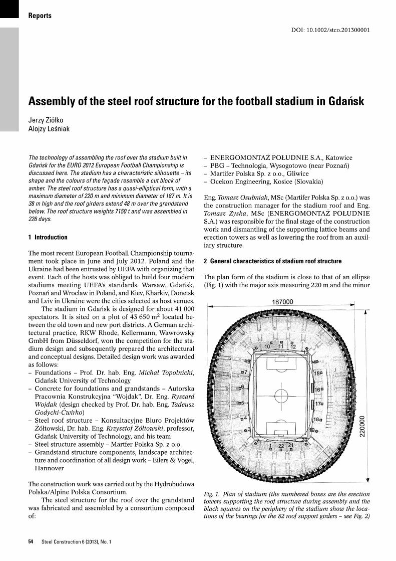
The plan form of the stadium is close to that of an ellipse (Fig. 1) with the major axis measuring 220 m and the minor
Assembly of the steel roof structure for the football stadium in GdanskJerzy ZiółkoAlojzy Lesniak
Fig. 1. Plan of stadium (the numbered boxes are the erection towers supporting the roof structure during assembly and the black squares on the periphery of the stadium show the loca-tions of the bearings for the 82 roof support girders – see Fig. 2)
Reports
55Steel Construction 6 (2013), No. 1
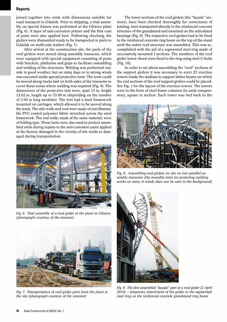
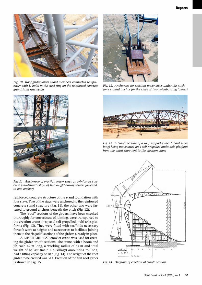
of the stand, only supported on it at 82 articulated joints on a support ring integrated into the floor at a height of about 7.0 m above ground level (Fig. 4). The pivot bearing for the steel roof girder has been achieved by welding the bottom ends of the upper and lower chords to a horizontal ∅ 500 × 24 mm circular hollow section and inserting this section into a cast steel cradle-type bearing (Fig. 5). The section transferring the support reaction to the bearing originally had a diameter of 508 mm and wall thickness of 28 mm, but was machined on the outside in order to fit the bearing exactly. The tube was subsequently filled with B28 class expanding concrete and closed with circular covers welded on the ends.
The total weight of the steel roof structure for the sta-dium in Gdansk amounted to 7150 t.
3 Assembly
Cutting of tubular sections for the frame bars for joining together at various angles and chamfering of edges for welding in various positions was carried out at the works in Kosice and partly at cooperating plants in Hungary. The prepared hollow sections were transported to the Martifer Metallic Constructions plant in Gliwice, where they were
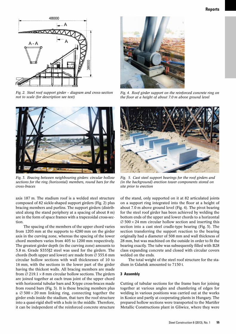
axis 187 m. The stadium roof is a welded steel structure composed of 82 sickle-shaped support girders (Fig. 2) plus bracing members and purlins. The support girders (distrib-uted along the stand periphery at a spacing of about 8 m) are in the form of space frames with a trapezoidal cross-sec-tion.
The spacing of the members of the upper chord varies from 1205 mm at the supports to 4280 mm on the girder axis in the curving zone, whereas the spacing of the lower chord members varies from 405 to 1200 mm respectively. The greatest girder depth (in the curving zone) amounts to 5.8 m. Grade S355J2 steel was used for the girders. The chords (both upper and lower) are made from ∅ 355.6 mm circular hollow sections with wall thicknesses of 10 to 16 mm, with the sections in the lower part of the girder having the thickest walls. All bracing members are made from ∅ 219.1 × 8 mm circular hollow sections. The girders are joined together at each truss joint of the upper chord with horizontal tubular bars and X-type cross-braces made from round bars (Fig. 3). It is these bracing members plus a ∅ 500 × 20 mm linking ring, connecting together the girder ends inside the stadium, that turn the roof structure into a quasi-rigid shell with a hole in the middle. Therefore, it can be independent of the reinforced concrete structure
Fig. 2. Steel roof support girder – diagram and cross-section not to scale (for description see text)
Fig. 3. Bracing between neighbouring girders: circular hollow sections for the ring (horizontal) members, round bars for the cross-braces
Fig. 4. Roof girder support on the reinforced concrete ring on the floor at a height of about 7.0 m above ground level
Fig. 5. Cast steel support bearings for the roof girders and (in the background) erection tower components stored on site prior to erection
Reports
56 Steel Construction 6 (2013), No. 1
The lower sections of the roof girders (the “façade” sec-tions), have been checked thoroughly for correctness of jointing, were transported directly to the reinforced concrete structure of the grandstand and mounted on the articulated bearings (Fig. 9). The respective roof girders had to be fixed to the reinforced concrete ring beam on the top of the stand until the entire roof structure was assembled. This was ac-complished with the aid of a segmented steel ring made of successively mounted I sections. The members of the roof girder lower chord were fixed to the ring using steel U-bolts (Fig. 10).
In order to set about assembling the “roof” sections of the support girders it was necessary to erect 22 erection towers inside the stadium to support lattice beams on which the end sections of the roof support girders could be placed. See Fig. 1 for the layout of the erection towers. The towers were in the form of steel frame columns (in axial compres-sion), square in section. Each tower was tied back to the
joined together into units with dimensions suitable for road transport to Gdansk. Prior to shipping, a trial assem-bly on special frames was performed at the Gliwice plant (Fig. 6). A layer of anti-corrosion primer and the first coat of paint were also applied here. Following checking, the girders were dismantled ready to be transported in parts to Gdansk on multi-axle trailers (Fig. 7).
After arrival at the construction site, the parts of the roof girders were stored along assembly transoms, which were equipped with special equipment consisting of posts with brackets, platforms and grips to facilitate assembling and welding of the structures. Welding was performed out-side in good weather, but on rainy days or in strong winds was executed inside special protective tents. The tents could be moved along tracks laid on both sides of the transoms to cover those zones where welding was required (Fig. 8). The dimensions of the protective tent were: span 13 m, height 12.62 m, length up to 35.09 m (depending on the number of 2.92 m long modules). The tent had a steel framework mounted on carriages, which allowed it to be moved along the track. The side walls and roof were made of non-flamma-ble PVC-coated polyester fabric stretched across the steel framework. The end walls, made of the same material, were of folding type. These tents were also used to protect assem-bled units during repairs to the anti-corrosion paint applied at the factory damaged in the vicinity of site welds or dam-aged during transportation.
Fig. 6. Trial assembly of a roof girder at the plant in Gliwice (photograph courtesy of the investor)
Fig. 7. Transportation of roof girder parts from the plant to the site (photograph courtesy of the investor)
Fig. 8. Assembling roof girders on site on two parallel as-sembly transoms (the movable tents for protecting welding works on rainy or windy days can be seen in the background)
Fig. 9. The first assembled “façade” part of a roof girder (2 April 2010) – temporary attachment of the girder to the segmented steel ring on the reinforced concrete grandstand ring beam
Reports
57Steel Construction 6 (2013), No. 1
reinforced concrete structure of the stand foundation with four stays. Two of the stays were anchored to the reinforced concrete stand structure (Fig. 11), the other two were fas-tened to ground anchors beneath the pitch (Fig. 12).
The “roof” sections of the girders, have been checked thoroughly for correctness of jointing, were transported to the erection crane on special self-propelled multi-axle plat-forms (Fig. 13). They were fitted with scaffolds necessary for safe work at heights and accessories to facilitate joining them to the “façade” sections of the girders already in place.
A LIEBHERR 1350 crawler crane was used for erect-ing the girder “roof” sections. The crane, with a boom and jib each 42 m long, a working radius of 34 m and total weight of ballast (main + auxiliary) amounting to 163 t, had a lifting capacity of 38 t (Fig. 14). The weight of the roof girder to be erected was 31 t. Erection of the first roof girder is shown in Fig. 15.
Fig. 10. Roof girder lower chord members connected tempo-rarily with U-bolts to the steel ring on the reinforced concrete grandstand ring beam
Fig. 11. Anchorage of erection tower stays on reinforced con-crete grandstand (stays of two neighbouring towers fastened to one anchor)
Fig. 12. Anchorage for erection tower stays under the pitch (one ground anchor for the stays of two neighbouring towers)
Fig. 13. A “roof” section of a roof support girder (about 48 m long) being transported on a self-propelled multi-axle platform from the paint shop tent to the erection crane
Fig. 14. Diagram of erection of “roof” section
Reports
58 Steel Construction 6 (2013), No. 1
Dismantling the supporting beams and erection tow-ers was an essential and technically difficult stage of the work. Dismantling was only possible after having welded together and checked the whole main ring connecting all the roof support girders. Once that was done, the contrac-tor had to set about disconnecting the roof support struc-ture from its temporary links to the reinforced concrete ring beam on the top of the stand; the roof support struc-ture had to become independent of the reinforced concrete structure. Cutting of the U-bolts joining the steel girders to
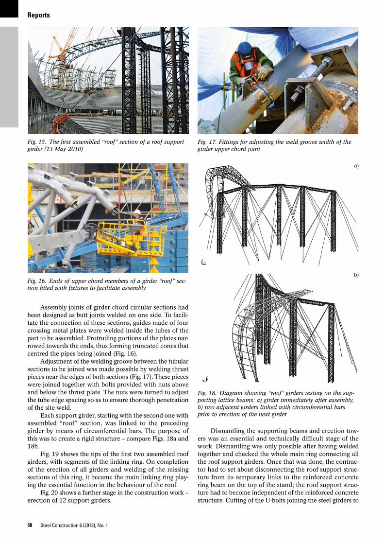
Assembly joints of girder chord circular sections had been designed as butt joints welded on one side. To facili-tate the connection of these sections, guides made of four crossing metal plates were welded inside the tubes of the part to be assembled. Protruding portions of the plates nar-rowed towards the ends, thus forming truncated cones that centred the pipes being joined (Fig. 16).
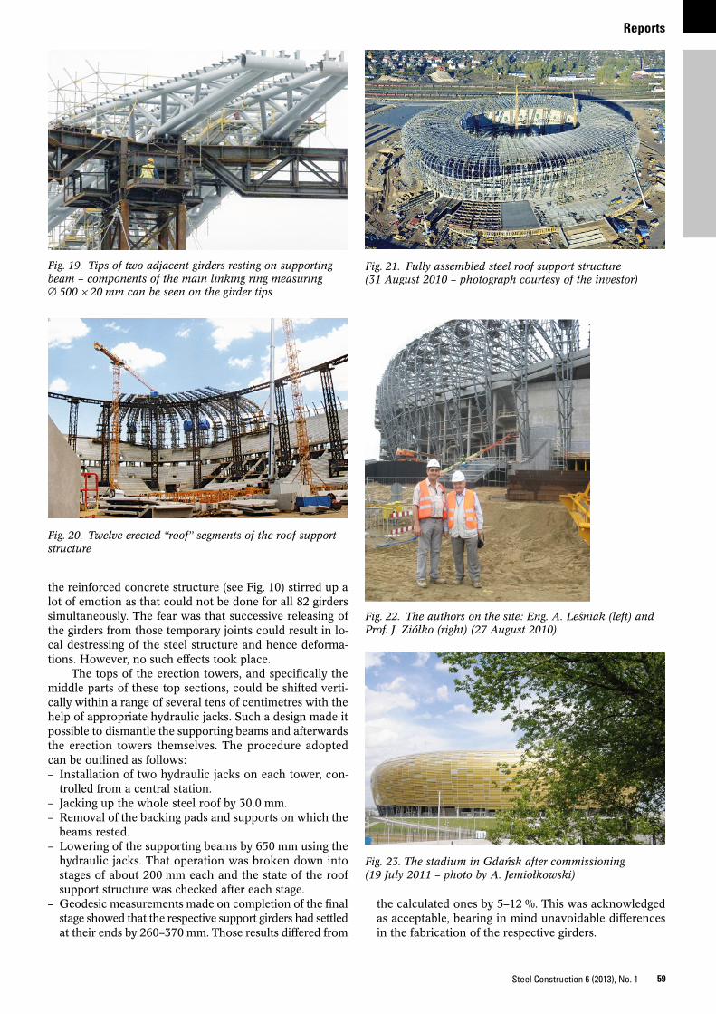
Adjustment of the welding groove between the tubular sections to be joined was made possible by welding thrust pieces near the edges of both sections (Fig. 17). These pieces were joined together with bolts provided with nuts above and below the thrust plate. The nuts were turned to adjust the tube edge spacing so as to ensure thorough penetration of the site weld.
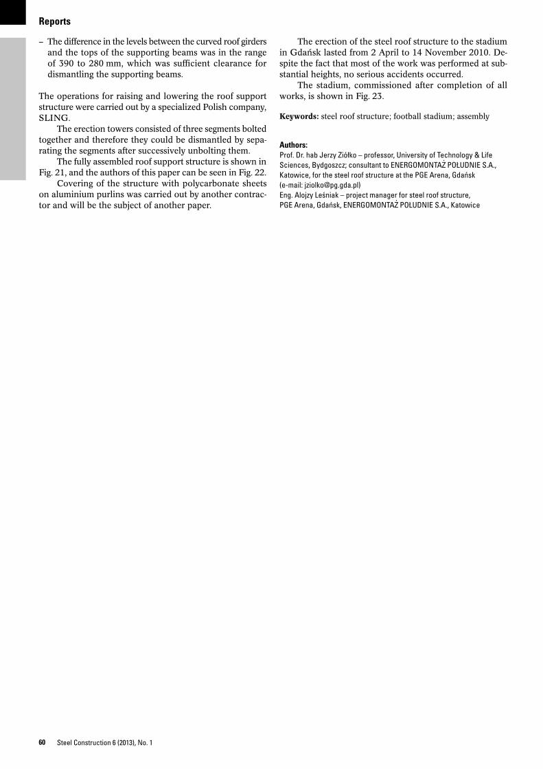
Each support girder, starting with the second one with assembled “roof” section, was linked to the preceding girder by means of circumferential bars. The purpose of this was to create a rigid structure – compare Figs. 18a and 18b.
Fig. 19 shows the tips of the first two assembled roof girders, with segments of the linking ring. On completion of the erection of all girders and welding of the missing sections of this ring, it became the main linking ring play-ing the essential function in the behaviour of the roof.
Fig. 20 shows a further stage in the construction work – erection of 12 support girders.
Fig. 15. The first assembled “roof” section of a roof support girder (13 May 2010)
Fig. 16. Ends of upper chord members of a girder “roof” sec-tion fitted with fixtures to facilitate assembly
Fig. 17. Fittings for adjusting the weld groove width of the girder upper chord joint
Fig. 18. Diagram showing “roof” girders resting on the sup-porting lattice beams: a) girder immediately after assembly, b) two adjacent girders linked with circumferential bars prior to erection of the next girder
a)
b)
Reports
59Steel Construction 6 (2013), No. 1
the reinforced concrete structure (see Fig. 10) stirred up a lot of emotion as that could not be done for all 82 girders simultaneously. The fear was that successive releasing of the girders from those temporary joints could result in lo-cal destressing of the steel structure and hence deforma-tions. However, no such effects took place.
The tops of the erection towers, and specifically the middle parts of these top sections, could be shifted verti-cally within a range of several tens of centimetres with the help of appropriate hydraulic jacks. Such a design made it possible to dismantle the supporting beams and afterwards the erection towers themselves. The procedure adopted can be outlined as follows:– Installation of two hydraulic jacks on each tower, con-
trolled from a central station.– Jacking up the whole steel roof by 30.0 mm.– Removal of the backing pads and supports on which the
beams rested.– Lowering of the supporting beams by 650 mm using the
hydraulic jacks. That operation was broken down into stages of about 200 mm each and the state of the roof support structure was checked after each stage.
– Geodesic measurements made on completion of the final stage showed that the respective support girders had settled at their ends by 260–370 mm. Those results differed from
the calculated ones by 5–12 %. This was acknowledged as acceptable, bearing in mind unavoidable differences in the fabrication of the respective girders.
Fig. 19. Tips of two adjacent girders resting on supporting beam – components of the main linking ring measuring ∅ 500 × 20 mm can be seen on the girder tips
Fig. 20. Twelve erected “roof” segments of the roof support structure
Fig. 21. Fully assembled steel roof support structure (31 August 2010 – photograph courtesy of the investor)
Fig. 22. The authors on the site: Eng. A. Lesniak (left) and Prof. J. Ziółko (right) (27 August 2010)
Fig. 23. The stadium in Gdansk after commissioning (19 July 2011 – photo by A. Jemiołkowski)
Reports
60 Steel Construction 6 (2013), No. 1
The erection of the steel roof structure to the stadium in Gdansk lasted from 2 April to 14 November 2010. De-spite the fact that most of the work was performed at sub-stantial heights, no serious accidents occurred.
The stadium, commissioned after completion of all works, is shown in Fig. 23.
Keywords: steel roof structure; football stadium; assembly
Authors:Prof. Dr. hab Jerzy Ziółko – professor, University of Technology & Life Sciences, Bydgoszcz; consultant to ENERGOMONTAZ
. POŁUDNIE S.A.,
Katowice, for the steel roof structure at the PGE Arena, Gdansk (e-mail: [email protected]) Eng. Alojzy Lesniak – project manager for steel roof structure, PGE Arena, Gdansk, ENERGOMONTAZ
. POŁUDNIE S.A., Katowice
– The difference in the levels between the curved roof girders and the tops of the supporting beams was in the range of 390 to 280 mm, which was sufficient clearance for dismantling the supporting beams.
The operations for raising and lowering the roof support structure were carried out by a specialized Polish company, SLING.
The erection towers consisted of three segments bolted together and therefore they could be dismantled by sepa-rating the segments after successively unbolting them.
The fully assembled roof support structure is shown in Fig. 21, and the authors of this paper can be seen in Fig. 22.
Covering of the structure with polycarbonate sheets on aluminium purlins was carried out by another contrac-tor and will be the subject of another paper.