gdi spray impact characterization by optical techniques ... · the impact of a spray on the piston...
TRANSCRIPT

Abstract— Design and optimization of injection systems for internal
combustion engines must be realized possibly by relying on detailed
analyses, as those achievable through multidimensional engine
modeling or by experimental investigations performed on optically
accessible engines or under engine like conditions in confined
vessels. As regards spark ignition engines, in particular, direct
injection technology is being considered as an effective mean to
achieve the optimal air-to-fuel ratio distribution at each engine
operating condition, either through charge stratification around the
spark plug, or by creating a stoichiometric mixture under the highest
power demands. The impact of a spray on the piston or cylinder walls
causes the formation of a liquid film (wallfilm) and the so-called
secondary atomization of droplets. The wallfilm may have no
negligible size, especially in cases where the mixture formation is
realized under a wall guided mode.
The present study is focused on the characterization of both a
multi-hole spray and a single hole spray in their impact over a cold or
hot plate. A 3D CFD model, whose assessment relies on the collected
experimental data, is also developed with the future scope of its
application within numerical simulations of entire engine working
cycles. A free spray sub-model of high portability allows correctly
predicting the spray dynamics at different injection conditions, while
the spray-wall impingement sub-model makes evident the gasoline
splashing and deposition phenomena.
Keywords—Computational fluid dynamics, GDI injection,
secondary evaporation, spray impact.
I. INTRODUCTION
IXTURE formation is fundamental for the development
of the combustion process in internal combustion
This work was in part supported by the Italian Government funding PON
01_1517: Innovative methodologies for the development of automotive
propulsion systems and PON 01_2211: Multiair evolution, an innovative
spark ignition propulsion system with ultra-low CO2 emissions.
L. Allocca is with the National Research Council of Italy (CNR), Istituto
Motori, Viale Marconi, 4 – 80125, Naples, ITALY (e-mail:
M. Costa is with the National Research Council of Italy (CNR), Istituto
Motori, Viale Marconi, 4 – 80125, Naples, ITALY (e-mail:
A. Montanaro is with the National Research Council of Italy (CNR),
Istituto Motori, Viale Marconi, 4 – 80125, Naples, ITALY (corresponding
author phone: +390817177223; fax: +390812396097; e-mail:
U. Sorge is with the National Research Council of Italy (CNR), Istituto
Motori, Viale Marconi, 4 – 80125, Naples, ITALY (e-mail:
engines, for the highest release of energy and the formation of
the lowest amount of undesired pollutants. Direct injection
(DI) in the combustion chamber is today regarded as the most
valuable solution for an effective engine control over the
whole working map of both compression ignition and spark
ignition engines. Today engines, indeed, strongly differ from
yesterday engines, so that traditional tools and techniques used
for their design are becoming insufficient for the required
challenges of energy and environmental performance, also due
to the fact that the fuels landscape is continuously evolving
and becoming more complex. In this change from a test-first
culture to an analysis-led design process, numerical simulation
tools, as CFD (computational fluid dynamics) models, are
becoming increasingly important to accelerate the time to
market of high-efficiency clean power sources for
transportation [1]. Assessing predictive numerical models is
therefore strongly demanded by the scientific community and
the manufacturers acting in the automotive field, especially to
correctly predict important phenomena as mixture formation in
DI engines.
Fuel delivery in the combustion chamber of an internal
combustion engine is realized through properly mounted
injectors delivering highly pressurized sprays in the intake air.
A fuel spray can be regarded as a train of droplets of different
size, suffering various concurring effects as they travel within
the surrounding atmosphere. Roughly speaking, aerodynamic
forces at the liquid air interface tends to amplify initial
perturbations to the liquid surface and to lead to instability and
detachment of small droplets, whereas surface tension tends to
preserve the initial shape of liquid surfaces. The net effect is
what is indicated as spray break-up or atomization into
droplets that are smaller and smaller as the distance from the
nozzle exit section increases. Initial droplets size at the
injector exit section may be regarded either as constant or as
variable according to some distribution, whose value or
expected value, respectively, is inversely proportional to the
square of the injection velocity [2]. This is proportional to the
square root of injection pressure, hence droplet diameter at the
exit section is practically inversely proportional to injection
pressure. This last is an important parameter strongly affecting
the mixture formation process, so much so that the
development of internal combustion engines in the last thirty
years has proceeded in strict conjunction with that of injection
systems.
GDI spray impact characterization by optical
techniques for the assessment of 3D numerical
models
Luigi Allocca, Michela Costa, Alessandro Montanaro, Ugo Sorge
M
New Developments in Mechanics and Mechanical Engineering
ISBN: 978-1-61804-288-0 42

In spray dynamics, an aspect that deserves particular
attention is its possible impact over cylinder or piston walls. In
particular, in GDI (gasoline direct injection) engines, a
quantity of injected fuel may be intentionally directed towards
the piston head, which exhibits a pit and an adjacent nose
redirecting droplets towards the spark plug (wall-guided
mixture formation) [3]. Spray droplets hitting on the surface
may be rebounded, stick to form a film, or undergo heating
and secondary evaporation. The deposited fuel on the wall
evaporates more slowly than free droplets, and may not permit
achieving the desired spatial distribution of the air-to-fuel ratio
prior to ignition. This may determine non effective combustion
development and formation of pollutants. The same deposition
of a gasoline film on the chamber walls is a relevant source of
unburned hydrocarbons and particulate matter [4]. Therefore,
controlling the amount of impacting droplets, their trajectory
and the evaporated gasoline mass after impact is a challenging
task, whose analysis needs a synergic use of advanced
experimental and numerical techniques [5].
Form the experimental point of view, the access to engine
combustion chambers is feasible only on laboratory engines.
Hence, studies concerning sprays is often effected through
experiments conducted within confined environments under
either non-evaporating or evaporating conditions that
reproduce engine like conditions. From the modelling
perspective, the dynamics of a free spray issuing in a gaseous
atmosphere must account for break-up, coalescence, turbulent
dispersion and evaporation. Available sub-models are often
empirical, due to the complexity of the involved phenomena,
and need a boring phase of tuning that strongly depends on the
expertise of the user. Modelling the outcome of an impinging
spray, on the other hand, could be carried out by focusing
attention on the impact of individual droplets on a surface, but
it is obvious that a droplet clouds behaves very differently
from a single one [6]. A critical review on the matter is
proposed by Moreira et al. [7]. From this work, it clearly
appears that experiments on single droplets have surely
contributed to identify various fluid-dynamic regimes of
droplet-wall interaction and to quantify size, velocity and
angle of ejection of secondary droplets, as well as of deposited
mass over surfaces. In dense sprays, on the other hand, the
impact between droplets has to be taken into account, as the
possible interaction with already deposited liquid films.
As regards heat transfer, the basics of transient boiling of
droplet streams and sprays consider four regimes [8]. At
relatively high surface temperatures, the liquid-solid contact is
very brief because the liquid is separated from the surface due
to an insulating vapor layer (film boiling regime). The lower
limit of temperature for this regime is the Leidenfrost point,
below which droplets partially enter into contact with the wall
and the heat transfer rate becomes inversely proportional to the
surface temperature (transition boiling regime). This occurs
until the critical heat flux (CHF) point is reached. As the
surface temperature further decreases, droplets make efficient
contact with the surface, and heat transfer reaches the highest
rates (nucleate boiling regime), till the so-called bubble
incipient point. Below this limit, boiling is a consequence of
single phase convection.
The just discussed reasoning clearly highlights the need for
studies devoted to characterize the spray impact over walls,
especially in cases where these are at high temperature, as in
the present work. The scope is the quantification of the effect
of temperature on the spray outcome after impact needed for
the assessment of 3D models suitable of being applied to the
simulation of the working cycle of a GDI engine for the
prediction of the termo-fluidynamic phenomena underlying the
energy conversion process and the optimization of the control
strategies.
Two kind of analyses are here performed. The first concerns
the impact on a wall of a spray generated by a multi-hole GDI
injector, that is experimentally characterized through image
acquisition by a CCD camera. The second consists in a more
basic study effected through the schileren technique of the
impact of a single hole spray. In both the cases different wall
temperatures are assumed. Commercial gasoline is used
(ρ=740 kg/m3) within all the tests, as delivered by a hydro-
pneumatic injection system without rotating organs. The
experimental work serves to the assessment of a predictive 3D
numerical model able to reproduce the whole phenomenon,
and, in particular, the secondary atomization occurring after
impact.
II. EXPERIMENTAL CHARACTERIZATION OF A MULTI-HOLE
SPRAY IMPACT
The considered GDI injector is a mini-sac 7-hole Bosch
HDEV 5.1 with solenoid actuation. It is characterized by a
hole diameter of 0.179 mm and a static flow rate of 13.7 g/s at
the injection pressure of 10 MPa. Figure 1 represents the
position of the 7 holes on the injector tip and the footprint of
the spray on a plane placed at a distance of 30 mm.
-0.02 -0.01 0 0.01 0.02x (m)
-0.008
0
0.008
0.016
y (
m)
z = 0
z = 30 mm
Figure 1. Injector hole distribution and spray footprint on a plane
placed at 30 mm from the injector tip.
A preliminary campaign is conducted to support the
validation of the developed 3D CFD numerical model,
consisting of three different kind of characterizations:
measurements of the delivered instantaneous mass flow rate
through a Bosch tube, images acquisition of the spray issuing
in an optically accessible vessel containing nitrogen under
controlled conditions of temperature and pressure (298 K and
0.1 MPa, respectively), images acquisition of the spray
impingement over a flat plate placed orthogonally to the
injector axis under cold and hot plate conditions. The injection
New Developments in Mechanics and Mechanical Engineering
ISBN: 978-1-61804-288-0 43

system and the synchronized image acquisition set-up are
managed by a programmable electronic control unit (PECU).
This is an open system able to reproduce the injector
energizing currents for the desired strategy in terms of number
of injection pulses, durations, rise and dwell times. The PECU
reproduces as an output a TTL signal, related to the injection
event, for synchronizing the consecutive images management
and acquisitions.
The gasoline mass flow rate is measured by means of an
AVL Fuel Injection Gauge Rate System working on the Bosch
tube principle [9, 10]. Figure 2 shows the link between the
solenoid energizing current profile and the corresponding fuel
injection rate measured by the AVL Meter at the injection
pressure of 15 MPa and for an energizing time of 1.46 ms. The
delay of 0.35 ms is observed between the activation of the
electronic signal and the first appearance of gasoline droplets
into the vessel. This is assumed in the following as the start of
injection (SOI). For the considered strategy the total amount of
injected fuel is equal to 26.21 mg/str.
Images of the spray, enlightened by powerful flashes, are
collected at different instants from SOI by means of a
synchronized CCD camera, 1376x1040 pixels, 12 bit
resolution, 0.5 µs shutter time. An overview of the
experimental scheme for the image acquisition is reported in
ref. [11]. The captured images are processed off-line by means
of a proper software, able to extract the parameters
characterizing the spray dynamics, namely penetration length
and cone angle of one of the seven jets compounding the
spray. A set of 5 images is collected for each injection
condition for a statistical analysis of the cycle-to-cycle
dispersion. The image processing analysis is carried out in
different steps: image acquisition and background subtraction,
filtering, fuel spray edges determination and tip penetration
measurements. Background subtraction and median filter
procedures allows removing the impulse noise and stray light,
so to maintain sharp the spray edge. This is determined by
selecting an intensity threshold level for separating the fuel
region from the background ambient gas.
-10
-5
0
5
10
15
20
25
30
-0,5 0,0 0,5 1,0 1,5 2,0 2,5 3,0
0
2
4
6
8
10
fuel in
j. r
ate
[m
g/m
s]
0.35 ms
Pinj
15 MPa
26,21 mg/str
sole
noid
curr
en
t [A
]
time [ms]
tinj
= 1,46 ms
Figure 2. Solenoid energizing current and fuel injection rate.
Characterization of the spray impingement on a wall is made
by introducing a stainless steel flat plate into the vessel. The
plate is located at 20 mm from the nozzle tip. The average
roughness of the wall is 1.077 µm, measured by the Stylus
Profilometer, Model Surtronic 3 by Rank Taylor Hobson. Two
cases are discussed, the first with the plate being at room
temperature, the second with a plate temperature of 200°C. All
the experiments are performed at ambient pressure and
temperature. Images of the spray impact are reported in
paragraph III, together with the relevant numerical results.
III. NUMERICAL SIMULATION OF A MULTI-HOLE SPRAY IMPACT
OVER A WALL
A. Free spray
The 3D sub-model able to simulate the dynamics of the
gasoline spray issuing from the considered injector is
developed in the context of the software AVL FireTM
[12], in
such a way to simulate the experiments performed by
mounting the injector and delivering sprays in an optically
accessible vessel. The followed approach is the classical
coupling between the Eulerian description of the gaseous
phase and the Lagrangian description of the liquid phase. The
governing equations are here not reported for the sake of
brevity; the interested reader may refer to the book by Ramos
[13]. The train of droplets entering the computational domain
in correspondence of the injector holes exit section suffers
various concurring effects as it travels. Details of the model
are given in the paper by Costa et al. [11]. Here it is only
worth pointing out that the droplets break-up phenomenon is
simulated according to the sub-model of Huh-Gosman [14]
whose constant C1 (regulating the break-up time) is adjusted
by means of a tuning procedure. The effects of the turbulent
dispersion on the droplets dynamics is simulated through the
sub-model by O’Rourke [15], coalescence through the sub-
model by Nordin [16], evaporation through the sub-model by
Dukowicz [17]. Initial size of droplets at the nozzle exit
section, is considered as variable according to a probabilistic
log-normal distribution, whose expected value is given by the
following theoretical diameter, where τf is the gasoline surface
tension, ρg the surrounding gas density, urel the relative
velocity between the fuel and the gas, Cd a constant of the
order of the unity (indeed taken equal to the unity), and λ* a
parameter deriving from the hydrodynamic stability analysis
and indicating the dimensionless wavelength of the more
unstable perturbation to the liquid-gas interface at the injector
exit section:
*
2
relg
fdth
u
2CD λ
ρ
πτ= . (1)
The variance of the distribution, σ, is another sub-model
parameter to be properly tuned.
Tuning is effected through an automatic procedure
developed by authors, that solves a single objective
optimization problem. In other words, instead of resorting to a
search of the values of the constants by trial and error, i.e. for
successive approximations, an optimization problem is set-up,
where the Simplex algorithm is used to reduce the error
New Developments in Mechanics and Mechanical Engineering
ISBN: 978-1-61804-288-0 44
between the results of the numerical computations and the
experimental measurements relevant to the penetration length.
The automatic procedure allows obtaining a model of high
"portability", i.e. such to be applied as it is to different
operating conditions, or even to sprays generated by different
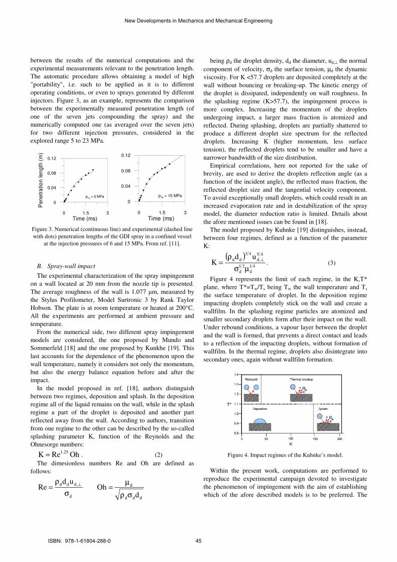
injectors. Figure 3, as an example, represents the comparison
between the experimentally measured penetration length (of
one of the seven jets compounding the spray) and the
numerically computed one (as averaged over the seven jets)
for two different injection pressures, considered in the
explored range 5 to 23 MPa.
0 1.5 3
Time (ms)
0
0.04
0.08
0.12
Pe
ne
tra
tion
le
ng
th (
m)
pinj = 6 MPa
0 1.5 3
Time (ms)
0
0.04
0.08
0.12
pinj = 15 MPa
Figure 3. Numerical (continuous line) and experimental (dashed line
with dots) penetration lengths of the GDI spray in a confined vessel
at the injection pressures of 6 and 15 MPa. From ref. [11].
B. Spray-wall impact
The experimental characterization of the spray impingement
on a wall located at 20 mm from the nozzle tip is presented.
The average roughness of the wall is 1.077 µm, measured by
the Stylus Profilometer, Model Surtronic 3 by Rank Taylor
Hobson. The plate is at room temperature or heated at 200°C.
All the experiments are performed at ambient pressure and
temperature.
From the numerical side, two different spray impingement
models are considered, the one proposed by Mundo and
Sommerfeld [18] and the one proposed by Kunkhe [19]. This
last accounts for the dependence of the phenomenon upon the
wall temperature, namely it considers not only the momentum,
but also the energy balance equation before and after the
impact.
In the model proposed in ref. [18], authors distinguish
between two regimes, deposition and splash. In the deposition
regime all of the liquid remains on the wall, while in the splash
regime a part of the droplet is deposited and another part
reflected away from the wall. According to authors, transition
from one regime to the other can be described by the so-called
splashing parameter K, function of the Reynolds and the
Ohnesorge numbers:
OhReK 25.1= . (2)
The dimesionless numbers Re and Oh are defined as
follows:
d
,ddd udRe
σ
ρ=
⊥
ddd
d
dOh
σρ
µ=
being ρd the droplet density, dd the diameter, ud,⊥ the normal
component of velocity, σd the surface tension, µd the dynamic
viscosity. For K <57.7 droplets are deposited completely at the
wall without bouncing or breaking-up. The kinetic energy of
the droplet is dissipated, independently on wall roughness. In
the splashing regime (K>57.7), the impingement process is
more complex. Increasing the momentum of the droplets
undergoing impact, a larger mass fraction is atomized and
reflected. During splashing, droplets are partially shattered to
produce a different droplet size spectrum for the reflected
droplets. Increasing K (higher momentum, less surface
tension), the reflected droplets tend to be smaller and have a
narrower bandwidth of the size distribution.
Empirical correlations, here not reported for the sake of
brevity, are used to derive the droplets reflection angle (as a
function of the incident angle), the reflected mass fraction, the
reflected droplet size and the tangential velocity component.
To avoid exceptionally small droplets, which could result in an
increased evaporation rate and in destabilization of the spray
model, the diameter reduction ratio is limited. Details about
the afore mentioned issues can be found in [18].
The model proposed by Kuhnke [19] distinguishes, instead,
between four regimes, defined as a function of the parameter
K:
( )41
d
21
d
45
,d
43
dd udK
µσ
ρ=
⊥. (3)
Figure 4 represents the limit of each regime, in the K,T*
plane, where T*=Tw/Ts being Tw the wall temperature and Ts
the surface temperature of droplet. In the deposition regime
impacting droplets completely stick on the wall and create a
wallfilm. In the splashing regime particles are atomized and
smaller secondary droplets form after their impact on the wall.
Under rebound conditions, a vapour layer between the droplet
and the wall is formed, that prevents a direct contact and leads
to a reflection of the impacting droplets, without formation of
wallfilm. In the thermal regime, droplets also disintegrate into
secondary ones, again without wallfilm formation.
Figure 4. Impact regimes of the Kuhnke’s model.
Within the present work, computations are performed to
reproduce the experimental campaign devoted to investigate
the phenomenon of impingement with the aim of establishing
which of the afore described models is to be preferred. The
New Developments in Mechanics and Mechanical Engineering
ISBN: 978-1-61804-288-0 45
simulation of the experiments is made from one hand to
validate the spray-wall interaction models, from the other to
actually evaluate the importance of keeping into account the
effects of the wall temperature on the reflected droplets
dynamics. The computation of the spray wall impingement is
started by preliminary simulating the heat transfer by natural
convection between the hot surface and the surrounding air,
before the spray injection, for a period of time reasonably
comparable with the heating time of the aluminum plate by the
thermal resistances. This allows considering the actual value of
the temperature of the air surrounding the plate at the time of
impingement.
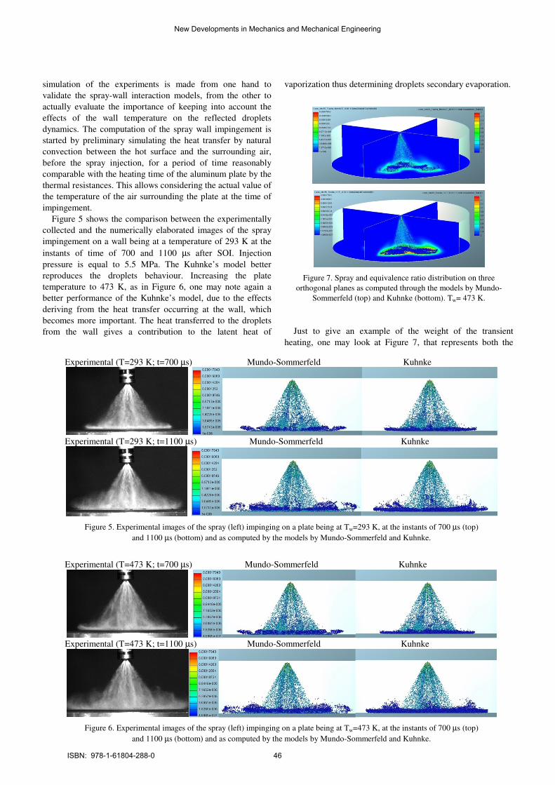
Figure 5 shows the comparison between the experimentally
collected and the numerically elaborated images of the spray
impingement on a wall being at a temperature of 293 K at the
instants of time of 700 and 1100 µs after SOI. Injection
pressure is equal to 5.5 MPa. The Kuhnke’s model better
reproduces the droplets behaviour. Increasing the plate
temperature to 473 K, as in Figure 6, one may note again a
better performance of the Kuhnke’s model, due to the effects
deriving from the heat transfer occurring at the wall, which
becomes more important. The heat transferred to the droplets
from the wall gives a contribution to the latent heat of
vaporization thus determining droplets secondary evaporation.
Figure 7. Spray and equivalence ratio distribution on three
orthogonal planes as computed through the models by Mundo-
Sommerfeld (top) and Kuhnke (bottom). Tw= 473 K.
Just to give an example of the weight of the transient
heating, one may look at Figure 7, that represents both the
Experimental (T=293 K; t=700 µs) Mundo-Sommerfeld Kuhnke
Experimental (T=293 K; t=1100 µs) Mundo-Sommerfeld Kuhnke
Figure 5. Experimental images of the spray (left) impinging on a plate being at Tw=293 K, at the instants of 700 µs (top)
and 1100 µs (bottom) and as computed by the models by Mundo-Sommerfeld and Kuhnke.
Experimental (T=473 K; t=700 µs) Mundo-Sommerfeld Kuhnke
Experimental (T=473 K; t=1100 µs) Mundo-Sommerfeld Kuhnke
Figure 6. Experimental images of the spray (left) impinging on a plate being at Tw=473 K, at the instants of 700 µs (top)
and 1100 µs (bottom) and as computed by the models by Mundo-Sommerfeld and Kuhnke.
New Developments in Mechanics and Mechanical Engineering
ISBN: 978-1-61804-288-0 46
spray and the equivalence ratio distribution of the air-gasoline
mixture on three orthogonal planes, one of which being the hot
plate, at the instant of time equal to 1100 µs after SOI, as
computed by the two models. The wall temperature is equal to
473K. A higher amount of gasoline in the vapour phase
derives from considering the heating effect of the wall,
according to the model proposed by Kuhnke. A measure of
this can be assumed as the relative difference in the global
equivalence ratio of the mixture, that reaches the 36% at the
considered instant of time of 1100 µs after SOI.
The reliable prediction of both the dynamics of a free spray
and the qualitative agreement of the simulation of the impact
on both a cold and a hot wall prove the suitability of the two-
phase flow sub-models of being included within a CFD model
of the whole engine working cycle.
IV. EXPERIMENTAL CHARACTERIZATION OF A SINGLE-HOLE
SPRAY IMPACT THROUGH SCHIELEREN TECHNIQUE
The second considered example is the impact of a single
hole spray, whose analysis is effected through the schieleren
technique.
A Magneti Marelli IHP-279 electro-injector is used, single-
hole axially-disposed, 0.200 mm in diameter, nozzle length to
diameter L/d=1 having a static flow of 2.45 g/s at 10.0 MPa
and driven by the home-made ECU. An 80 mm diameter
aluminum flat plate is positioned 22.5 mm downstream of the
injector tip, orthogonally to the spray axis. The plate is heated
in the range 298 – 573 K by electric resistances and controlled
in temperature by a J-type thermocouple located in its center,
1.0 mm below the wall surface. A Watlow series 985
thermostatic system fixes and controls the temperature in a
range of +/- 1 K.
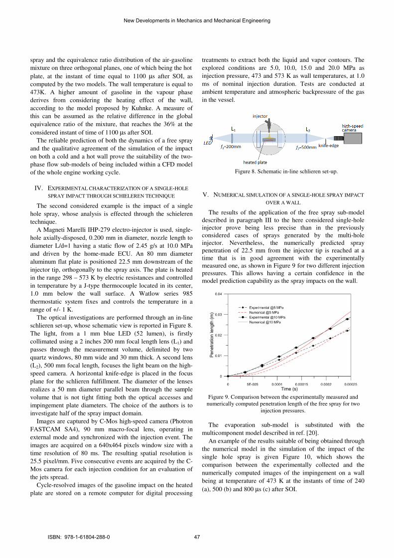
The optical investigations are performed through an in-line
schlieren set-up, whose schematic view is reported in Figure 8.
The light, from a 1 mm blue LED (52 lumen), is firstly
collimated using a 2 inches 200 mm focal length lens (L1) and
passes through the measurement volume, delimited by two
quartz windows, 80 mm wide and 30 mm thick. A second lens
(L2), 500 mm focal length, focuses the light beam on the high-
speed camera. A horizontal knife-edge is placed in the focus
plane for the schlieren fulfillment. The diameter of the lenses
realizes a 50 mm diameter parallel beam through the sample
volume that is not tight fitting both the optical accesses and
impingement plate diameters. The choice of the authors is to
investigate half of the spray impact domain.
Images are captured by C-Mos high-speed camera (Photron
FASTCAM SA4), 90 mm macro-focal lens, operating in
external mode and synchronized with the injection event. The
images are acquired on a 640x464 pixels window size with a
time resolution of 80 ms. The resulting spatial resolution is
25.5 pixel/mm. Five consecutive events are acquired by the C-
Mos camera for each injection condition for an evaluation of
the jets spread.
Cycle-resolved images of the gasoline impact on the heated
plate are stored on a remote computer for digital processing
treatments to extract both the liquid and vapor contours. The
explored conditions are 5.0, 10.0, 15.0 and 20.0 MPa as
injection pressure, 473 and 573 K as wall temperatures, at 1.0
ms of nominal injection duration. Tests are conducted at
ambient temperature and atmospheric backpressure of the gas
in the vessel.
Figure 8. Schematic in-line schlieren set-up.
V. NUMERICAL SIMULATION OF A SINGLE-HOLE SPRAY IMPACT
OVER A WALL
The results of the application of the free spray sub-model
described in paragraph III to the here considered single-hole
injector prove being less precise than in the previously
considered cases of sprays generated by the multi-hole
injector. Nevertheless, the numerically predicted spray
penetration of 22.5 mm from the injector tip is reached at a
time that is in good agreement with the experimentally
measured one, as shown in Figure 9 for two different injection
pressures. This allows having a certain confidence in the
model prediction capability as the spray impacts on the wall.
Figure 9. Comparison between the experimentally measured and
numerically computed penetration length of the free spray for two
injection pressures.
The evaporation sub-model is substituted with the
multicomponent model described in ref. [20].
An example of the results suitable of being obtained through
the numerical model in the simulation of the impact of the
single hole spray is given Figure 10, which shows the
comparison between the experimentally collected and the
numerically computed images of the impingement on a wall
being at temperature of 473 K at the instants of time of 240
(a), 500 (b) and 800 µs (c) after SOI.
New Developments in Mechanics and Mechanical Engineering
ISBN: 978-1-61804-288-0 47

More precisely, the experimental images (top) are
represented, as they are collected and after the filtering
procedure (middle), whereas the numerical images (bottom)
represent the liquid droplets and the vapor phase distribution
on a plane passing through the spray axis. Evaporation is the
result of both the multi-component primary evaporation of
gasoline and the secondary evaporation consequent the impact
event. Injection pressure, along the columns, is equal to 10
Figure 10. Comparison between experimentally collected (top), processed (middle) and numerically computed (bottom) images of spray
impact. Numerical results are represented as the liquid droplet cloud and as distribution of the mixture equivalence ratio on a plane passing
through the spray axis at Tw=473 K for 240 (a), 500 (b), and 800 ms (c) after SOI and for pinj=10 (left), 15 (center) and 20 MPa (right).
New Developments in Mechanics and Mechanical Engineering
ISBN: 978-1-61804-288-0 48
(left), 15 (center), and 20 MPa (right). The effects of the
injection pressure on the experimental images are marked in
moving from left (10 MPa) to right (20 MPa). At the same
interval of time after SOI, the higher the injection pressure, the
longer is the width penetration because of the increased
velocity (and the component parallel to the plate surface) of
the impacting droplets. The highest velocity of the spray
produces a better atomization of the fuel bulk just at the nozzle
exit section. In fact, the vapor phase diffusion at 240 ms is
wider with increasing pressure, as it is in the free evolving
phase (center and right of the figure). Furthermore, despite of a
largest amount of injected fuel at 20 MPa the vapor phase
increases prominently, with respect to the lowest pressure, due
to a finest atomization consequent the highest impact velocity
and to an easier vaporization. This reflects into a greatest
amount of vapor and in a more complex fluid dynamic
behavior with curls and bouncing. The history repeats at 500
and 800 µs with more intricate fluid dynamic behaviors due to
a greatest multitude of impacting droplets. The numerical
results correctly predict the experiments at 500 and 800 ms
from the SOI and at the highest pressures while they tend to
overestimate the penetrations at early stage of injection.
The Kuhnke’s model is here properly adjusted. In particular,
the heat penetration coefficient at the interface between the
wall and the liquid, b, that is accounted for in the Wruck’s
assumption about the transient heat transfer, is calculated with
reference to the aluminum properties. The following equation
is employed:
ckb ρ= , (4)
where k is the thermal conductivity, r is the density and c is
specific heat [21]. The Wruck’s schematization considers both
the wall and the droplets as semi-infinite media with respect to
the instantaneous contact point. The heat transferred to the
droplets from the wall contributes to the latent heat of
vaporization and determines the secondary evaporation. The
external contour of the computed vapor phase distribution is
quite in a reasonable agreement with the one experimentally
evaluated through the schieleren technique. The need of a
proper use of the model proposed by Kuhnke is evident since
the gasoline mass in the vapor phase, hence the vapor phase
diffusion, may be underestimated in the case the model is
applied in its default state. This clearly shows the importance
of having at disposal reliable measurements of the vapor
diffusion consequent the impact of a spray on a wall, that,
indeed, are hardly realizable, especially under real engine
operating conditions. At the injection pressure of 10 MPa, left
side of Figure 10, the width of the vapor phase seems initially
overestimated. At greater times, this quantity is instead
underestimated because of the great influence of the deposition
regime. This effect also influences the vapor layer height,
which is lower in the numerical analysis. The model proposed
by Kuhnke, indeed, is not yet optimized to account for the
evaporation from the wall-film, thus indicating the need of its
revision with respect to this aspect. Figure 10 also shows that
increasing the injection pressure increases the vapor layer
width, in agreement with the experimental findings and the
expected behavior of an impinging spray.
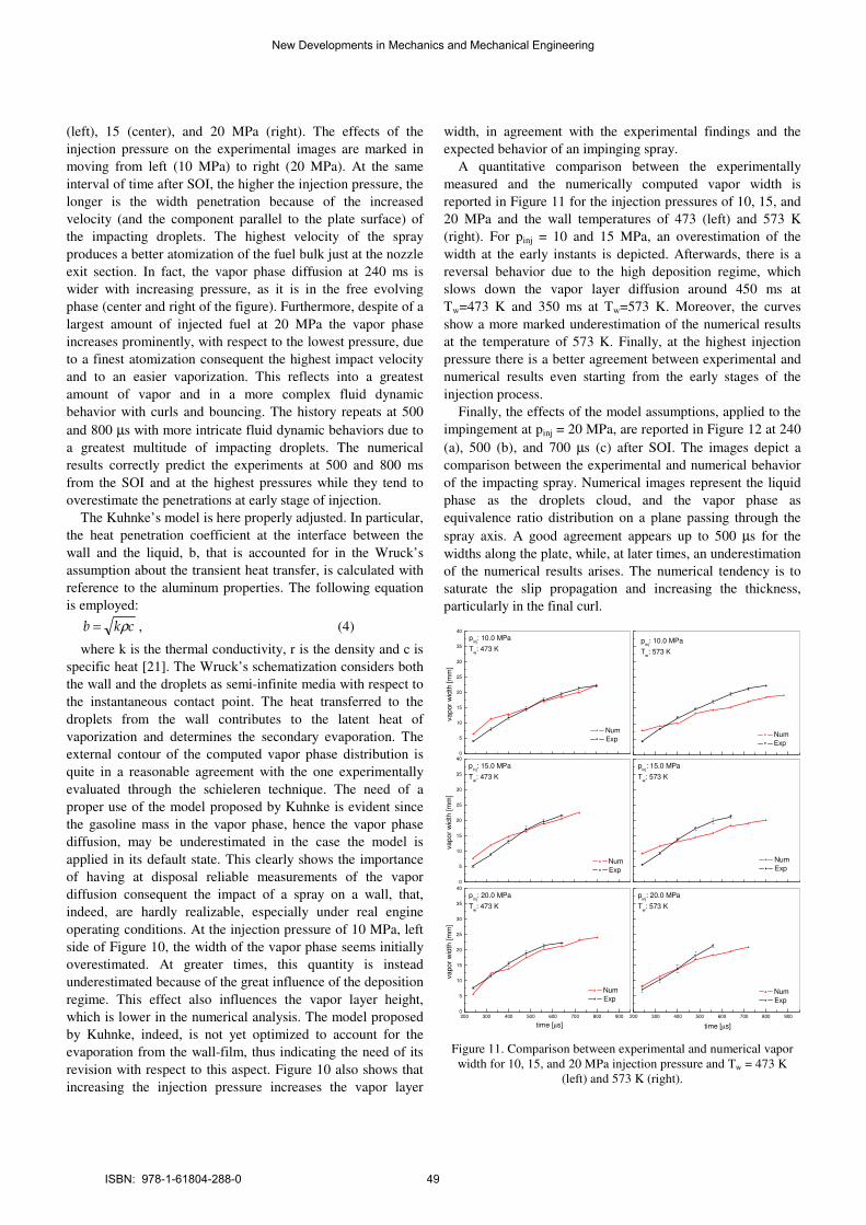
A quantitative comparison between the experimentally
measured and the numerically computed vapor width is
reported in Figure 11 for the injection pressures of 10, 15, and
20 MPa and the wall temperatures of 473 (left) and 573 K
(right). For pinj = 10 and 15 MPa, an overestimation of the
width at the early instants is depicted. Afterwards, there is a
reversal behavior due to the high deposition regime, which
slows down the vapor layer diffusion around 450 ms at
Tw=473 K and 350 ms at Tw=573 K. Moreover, the curves
show a more marked underestimation of the numerical results
at the temperature of 573 K. Finally, at the highest injection
pressure there is a better agreement between experimental and
numerical results even starting from the early stages of the
injection process.
Finally, the effects of the model assumptions, applied to the
impingement at pinj = 20 MPa, are reported in Figure 12 at 240
(a), 500 (b), and 700 µs (c) after SOI. The images depict a
comparison between the experimental and numerical behavior
of the impacting spray. Numerical images represent the liquid
phase as the droplets cloud, and the vapor phase as
equivalence ratio distribution on a plane passing through the
spray axis. A good agreement appears up to 500 µs for the
widths along the plate, while, at later times, an underestimation
of the numerical results arises. The numerical tendency is to
saturate the slip propagation and increasing the thickness,
particularly in the final curl.
0
5
10
15
20
25
30
35
40
pinj
: 10.0 MPa
Tw: 473 K
va
por
wid
th [
mm
]
Num
Exp
pinj
: 10.0 MPa
Tw: 573 K
Num
Exp
0
5
10
15
20
25
30
35
40
pinj
: 15.0 MPa
Tw: 473 K
va
po
r w
idth
[m
m]
Num
Exp
200 300 400 500 600 700 800 9000
5
10
15
20
25
30
35
40
pinj
: 20.0 MPa
Tw: 473 K
time [µs]
va
po
r w
idth
[m
m]
Num
Exp
pinj
: 15.0 MPa
Tw: 573 K
Num
Exp
200 300 400 500 600 700 800 900
pinj
: 20.0 MPa
Tw: 573 K
time [µs]
Num
Exp
Figure 11. Comparison between experimental and numerical vapor
width for 10, 15, and 20 MPa injection pressure and Tw = 473 K
(left) and 573 K (right).
New Developments in Mechanics and Mechanical Engineering
ISBN: 978-1-61804-288-0 49

Figure 12. Comparison between experimentally collected (top),
processed (middle) and numerically computed (bottom) images of
spray impact at 240 (a), 500 (b), and 700 µs (c) after SOI for pinj=20
MPa and Tw = 573 K. Numerical images show droplets and
equivalence ratio on a plane passing through the spray axis.
Increasing the wall temperature from 473 to 573 K enhances
the secondary evaporation, as shown in Figure 13, where the
comparison between experimental data and numerical results
relevant to the same injection pressure, 15 MPa, and time
ASOI, 500 µs, at Tw=473 (left) and 573 K (right) is reported.
Increasing the wall temperature has an effect on both the liquid
phase, with much dispersed droplets, and on the vapor phase
whose diffusion appears increased in both the directions
orthogonal and parallel to the wall. The effect in the direction
orthogonal to the wall is more evident.
Figure 13. Comparison between experimentally collected (top) and
numerically computed (bottom) images of the spray impact at 500 µs
ASOI for pinj = 15 MPa and Tw = 473 K (left) and Tw = 573 K
(right).
VI. CONCLUSION
Multiple droplet impacts, liquid deposition over piston or
cylinder walls, secondary atomization, heat transfer on spray
impaction in GDI engines depend upon injection timing, that is
the most essential engine operating parameter for mixture
formation and combustion development. By simply varying
time of injection, one may either realize homogeneous charges
(stoichiometric or rich) either stratified charges, characterized
by a rich zone around the spark plug and leaner zones towards
the walls for an overall lean operation and lower heat losses at
the liner. Injector requirements are however more stringent for
stratified combustion to ensure that a combustible charge is
properly prepared for ignition by the spark plug. A factor
playing a relevant role in the mixture preparation is the spray
impact on piston or cylinder walls, which may be intentional,
as in wall guided systems, or unintentional and anyway such to
create non optimal mixing of gasoline with air and to be an
undesired source of pollutants. Present work considers the
impact of both a GDI multi-hole spray and a single hole spray
over a cold or hot wall. The collected data serve to evaluate
the droplet behavior after impact, with the main aim of
assessing a predictive numerical 3D CFD model suitable of
being included within simulations of entire engine working
cycles. Although a commercial software environment is used,
the choice of the more suitable sub-models needs a careful
comparison with experimental data relevant to engine like
conditions.
Between available models the one proposed by Kuhnke
reveals quite appropriate to reproduce the liquid rebounding
New Developments in Mechanics and Mechanical Engineering
ISBN: 978-1-61804-288-0 50

and splashing and the secondary evaporation consequent the
droplet transient heating. An underestimation of the vapor
diffusion is however noticed in still air conditions, that,
however, is believed to have a lower weight when actual
engine operation is treated, due to the intense charge motion
and the high level of turbulence intensity characterizing the
operation of real engines.
REFERENCES
[1] R. W. Carling, “Predictive Simulation of Combustion Engine
Performance in an Evolving Fuel Environment”, Sandia National
Laboratories Report, 2010.
[2] J. B. Heywood, Internal Combustion engine fundamentals. New York:
McGraw-Hill, 1998.
[3] C.Wang, H. Xu, J. M. Herreros, J. Wang, R. Crancknell, “Impact of
Fuel and Injection System on Particle Emissions from a GDI Engine”,
Applied Energy, vol. 132, pp. 178–191, 2014.
[4] Y. S. Shim, G. M. Choi, D. J. Kim, “Numerical and Experimental
Study on Effect of Wall Geometry on Wall Impingement Process of
Hollow Cone Fuel Spray under Various Ambient Conditions”,
International Journal of Multiphase Flow, vol. 35, pp. 885-895, 2009.
[5] M. C. Drake, D. C. Haworth, “Advanced Gasoline Engine Development
Using Optical Diagnostic and Numerical Modeling”, Proceedings of the
Combustion Institute, vol. 31, pp. 99-124, 2007.
[6] N. Ashgriz Ed., Handbook of Atomization and Sprays - Theory and
Applications, Springer, New York, 2011.
[7] A. L. N. Moreira, A. S. Moita, M. R. Panao, “Advances and Challenges
in Explaining Fuel Spray Impingement: How Much of Single Droplet
Impact Research is Useful?”, Progress in Energy and Combustion
Science, vol. 36, pp. 554-580, 2010.
[8] J. D. Bernardin, I. Mudawar, “Transition Boiling Heat Transfer of
Droplets Streams and Sprays”, Journal of Heat Transfer, vol. 129, pp.
1605-1610, 2007.
[9] W. Bosch, SAE Technical Paper 6607496, 1966.
[10] I. Wallace,., “Injection Rate Gauge: Pass Off Information and User
Instructions”, Graz, 2002.
[11] M.Costa, U. Sorge, L., Allocca, “CFD optimization for GDI spray model
tuning and enhancement of engine performance”, Advances in
Engineering Software, 49, pp. 43-53, 2012.
[12] https://www.avl.com/web/ast/fire
[13] J. I. Ramos, Internal Combustion Engine Modelling, CRC Press, 1989.
[14] K. Y. Huh, A. D. Gosman, “A Phenomenological Model of Diesel Spray
Atomization”, International Conference on Multiphase Flows, Tsukuba,
Japan, 1991.
[15] P. J. O’Rourke, F. V. Bracco, “Modeling of Drop Interactions in Thick
Sprays and a Comparison with Experiments”, IMECHE, London, 1980.
[16] N. Nordin, “Complex Chemical Modeling of Diesel Spray
Combustion”, PhD Thesis, Chalmers University of Technology, 2001.
[17] J. K. Dukowicz, “Quasi-Steady Droplet Change in the Presence of
Convection”, informal report Los Alamos Scientific Laboratory, Los
Alamos Report LA7997-MS, 1979.
[18] C. Mundo , M. Sommerfeld, C. Tropea, “Droplet-Wall Collisions:
Experimental Studies of the Deformation and Breakup Process”,
International Journal of Multiphase Flows, vol. 21(2), pp. 151-173,
1995.
[19] D. Kuhnke, “Spray Wall Interaction Modeling by Dimensionless Data
Analysis”, PhD Thesis, Technische Universität Darmstadt, 2004.
[20] G. Brenn, L. J. Deviprasath, F.Durst, “Computations and Experiments
on the Evaporation of Multi-Component Droplets”, Proceedings 9th
International Conference Liquid Atomization Spray Systems (ICLASS),
Sorrento, 2003.
[21] N.Wruck, U. Renz, “Transient Phase-Change of Droplets Impacting on
a Hot Wall”, Transient Phenomena in Multiphase and Multicomponent
Systems: Research Report, pp. 210–226, 2007.
New Developments in Mechanics and Mechanical Engineering
ISBN: 978-1-61804-288-0 51