ge consumer & industrial technical service guide · technical service guide july 2006 ... the...
TRANSCRIPT
GCG1500BBGCG1500WWGCG1580SSGCG1700IIZCGS150SSZCGP150II
GE AppliancesGeneral Electric CompanyLouisville, Kentucky 40225
31-9143
15-in. Built-InCompactors
Technical Service GuideJULY 2006
GE Consumer & Industrial
– 2 –
IMPORTANT SAFETY NOTICE
The information in this service guide is intended for use by individuals possessing adequate backgrounds of electrical, electronic, and mechanical experience. Any attempt to repair a major appliance may result in personal injury and property damage. The manufacturer or seller cannot be responsible for the interpretation of this information, nor can it assume any liability in connection with its use.
WARNING
To avoid personal injury, disconnect power before servicing this product . If electrical power is required for diagnosis or test purposes, disconnect the power immediately after performing the necessary checks.
RECONNECT ALL GROUNDING DEVICES
If grounding wires, screws, straps, clips, nuts, or washers used to complete a path to ground are removed for service, they must be returned to their original position and properly fastened.
GE Consumer & IndustrialTechnical Service Guide
Copyright © 2006All rights reserved. This service guide may not be reproduced in whole or in part in any form without written permission from the General Electric Company.
– 3 –
Table of Contents
Built-In Compactor Components .............................................................................................................................. 13
Care and Cleaning of the Built-In Compactor .................................................................................................... 10
Chain ....................................................................................................................................................................................... 22
Component Locator Views ........................................................................................................................................... 11
Control Panel ...................................................................................................................................................................... 13
Control Features ............................................................................................................................................................... 7
Diagnostics and Service Information ...................................................................................................................... 23
Directional Switch ............................................................................................................................................................. 14
Features ................................................................................................................................................................................ 4
Installation Requirements ............................................................................................................................................. 5
Motor Assembly ................................................................................................................................................................ 17
Nomenclature .................................................................................................................................................................... 6
ON-OFF Switch ................................................................................................................................................................... 14
Power Screw Assembly .................................................................................................................................................. 21
Ram Assembly ................................................................................................................................................................... 19
Schematic ............................................................................................................................................................................ 25
Start Switch ......................................................................................................................................................................... 15
Switch Bracket ................................................................................................................................................................... 13
Tilt Switch ............................................................................................................................................................................. 15
Tilt Switch (Drawer) .......................................................................................................................................................... 16
Top Cover Panel ................................................................................................................................................................. 16
Top Limit Switch ................................................................................................................................................................ 14
Using the Built-In Compactor ...................................................................................................................................... 8
Warranty .............................................................................................................................................................................. 26

– 4 –
ZCG
P150
LII
ZCG
S150
LSS
GC
G15
00LB
B/W
WG
CG
1580
LSS
GC
G17
00LI
IC
APA
CIT
Y
Cap
acity
1,4
cu. f
t.1.
4 cu
. ft.
1.4
cu. f
t.1.
4 cu
. ft.
1.4
cu. f
t.FE
ATU
RES
C
ompr
essi
on R
atio
(Avg
.)75
% R
educ
tion
or 4
:175
% R
educ
tion
or 4
:175
% R
educ
tion
or 4
:175
% R
educ
tion
or 4
:175
% R
educ
tion
or 4
:1
Con
trol L
ocat
ion
Hid
den
Hid
den
Hid
den
Hid
den
Hid
den
C
ycle
Tim
eLe
ss th
an 2
5 se
cond
sLe
ss th
an 2
5 se
cond
sLe
ss th
an 3
0 se
cond
sLe
ss th
an 3
0 se
cond
sLe
ss th
an 3
0 se
cond
s
Driv
e S
yste
m2-
poin
t2-
poin
t2-
poin
t2-
poin
t2-
poin
t
Mot
or H
orse
pow
er1/
3 hp
1/3
hp1/
3 hp
1/3
hp1/
3 hp
R
am F
orce
(lb.
)23
00 lb
s.23
00 lb
s.23
00 lb
s.23
00 lb
s.23
00 lb
s.
Aut
omat
ic A
nti-J
amY
esY
esN
oN
oN
o
Loc
k/S
tart
Con
trol w
/Rem
ovab
le K
eyY
esY
esY
esY
esY
es
Sid
e R
elea
se B
inY
esY
esY
esY
esY
es
Slid
e-O
ut D
raw
erY
esY
esY
esY
esY
es
Bag
Cad
dyY
esY
esN
oN
oN
o
Bui
lt-In
Yes
Yes
Yes
Yes
Yes
APP
EAR
AN
CE
L
evel
ing
Legs
Yes
(w/ r
ear w
heel
s)Y
es (w
/ rea
r whe
els)
Yes
(w/ r
ear w
heel
s)Y
es (w
/ rea
r whe
els)
Yes
(w/ r
ear w
heel
s)
Col
or A
ppea
ranc
eC
usto
m P
anel
s R
equi
red
Sta
inle
ss S
teel
Bla
ck/W
hite
Sta
inle
ss S
teel
Cus
tom
Pan
els
Req
uire
d
Col
or A
ppea
ranc
e C
ode
IIS
SB
B/W
WS
SII
D
oor/C
ontro
l Pan
el C
olor
SS
T
oe K
ick
Bla
ck a
nd S
tain
less
Ste
elB
lack
and
Sta
inle
ss S
teel
Bla
ck a
nd S
tain
less
Ste
elB
lack
and
Sta
inle
ss S
teel
Bla
ck a
nd S
tain
less
Ste
el
3/4
" Pan
el C
apab
ility
Yes
No
No
No
Yes
WEI
GH
TS &
DIM
ENSI
ON
S
App
roxi
mat
e S
hipp
ing
Wei
ght
144
lb14
4 lb
144
lb14
4 lb
144
lb
Cab
inet
Wid
th15
1/8
in15
1/8
in15
in15
in15
in
Net
Wei
ght (
lbs.
)12
8 lb
128
lb12
8 lb
128
lb12
8 lb
O
vera
ll D
epth
24 in
24 in
23 in
24 in
23 in
O
vera
ll H
eigh
t33
3/4
in33
3/4
in33
3/4
in33
3/4
in33
3/4
in
Ove
rall
Wid
th14
7/8
in14
7/8
in14
7/8
in14
7/8
in14
7/8
in
Cut
out D
imen
sion
s (H
x W
x D
inch
es)
34-1
/4 x
15-
1/8
x 24
-3/4
34-1
/4 x
15-
1/8
x 24
-3/4
34-1
/4 x
15-
1/8
x 24
-3/4
34-1
/4 x
15-
1/8
x 24
-3/4
34-1
/4 x
15-
1/8
x 24
-3/4
H
eigh
t w/L
egs
Ext
ende
d (in
.)35
3535
3535
H
eigh
t With
Leg
s R
etra
cted
(In.
)33
-3/4
33-3
/433
-3/4
33-3
/433
-3/4
POW
ER /
RA
TIN
GS
V
olts
/Her
tz/A
mps
120
V; 6
0 H
z; 7
.0 A
120
V; 6
0 H
z; 7
.0 A
120
V; 6
0 H
z; 6
.5 A
120
V; 6
0 H
z; 6
.5 A
120
V; 6
0 H
z; 6
.5 A
WA
RR
AN
TY
Par
ts a
nd L
abor
War
rant
yLi
mite
d 1-
year
ent
ire a
pplia
nce
Lim
ited
1-ye
ar e
ntire
app
lianc
eLi
mite
d 1-
year
ent
ire a
pplia
nce
Lim
ited
1-ye
ar e
ntire
app
lianc
eLi
mite
d 1-
year
ent
ire a
pplia
nce
Features
– 5 –
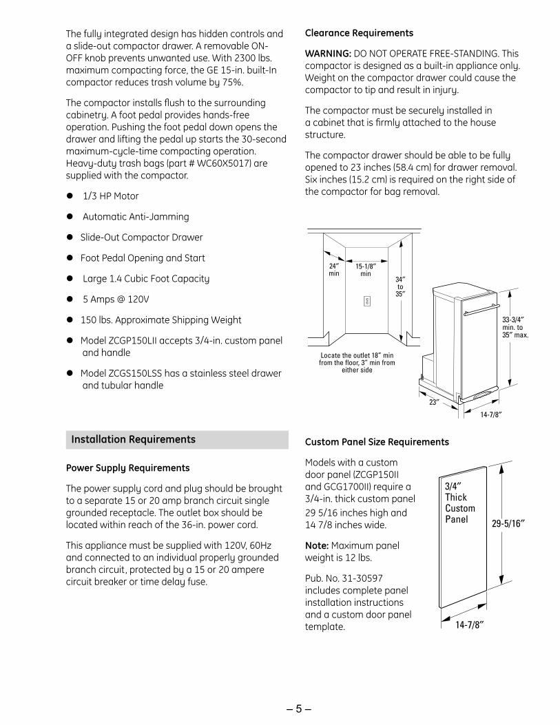
Clearance Requirements
WARNING: DO NOT OPERATE FREE-STANDING. This compactor is designed as a built-in appliance only. Weight on the compactor drawer could cause the compactor to tip and result in injury.
The compactor must be securely installed in a cabinet that is firmly attached to the house structure.
The compactor drawer should be able to be fully opened to 23 inches (58.4 cm) for drawer removal. Six inches (15.2 cm) is required on the right side of the compactor for bag removal.
29-5/16″
14-7/8″
3/4″ThickCustomPanel
Custom Panel Size Requirements
Models with a custom door panel (ZCGP150II and GCG1700II) require a 3/4-in. thick custom panel 29 5/16 inches high and 14 7/8 inches wide.
Note: Maximum panel weight is 12 lbs.
Pub. No. 31-30597 includes complete panel installation instructions and a custom door panel template.
Installation Requirements
Power Supply Requirements
The power supply cord and plug should be brought to a separate 15 or 20 amp branch circuit single grounded receptacle. The outlet box should be located within reach of the 36-in. power cord.
This appliance must be supplied with 120V, 60Hz and connected to an individual properly grounded branch circuit, protected by a 15 or 20 ampere circuit breaker or time delay fuse.
33-3/4″min. to 35″ max.
14-7/8″
23″
34″to
35″
15-1/8″min
24″min
Locate the outlet 18” minfrom the floor, 3” min from
either side
The fully integrated design has hidden controls and a slide-out compactor drawer. A removable ON-OFF knob prevents unwanted use. With 2300 lbs. maximum compacting force, the GE 15-in. built-In compactor reduces trash volume by 75%.
The compactor installs flush to the surrounding cabinetry. A foot pedal provides hands-free operation. Pushing the foot pedal down opens the drawer and lifting the pedal up starts the 30-second maximum-cycle-time compacting operation. Heavy-duty trash bags (part # WC60X5017) are supplied with the compactor.
1/3 HP Motor
Automatic Anti-Jamming
Slide-Out Compactor Drawer
Foot Pedal Opening and Start
Large 1.4 Cubic Foot Capacity
5 Amps @ 120V
150 lbs. Approximate Shipping Weight
Model ZCGP150LII accepts 3/4-in. custom panel and handle
Model ZCGS150LSS has a stainless steel drawer and tubular handle

– 6 –
Monogram
The nomenclature plate is located on the interior front panel at the top, left corner of the compactor drawer.
The mini-manual is located behind the control panel.
Nomenclature
The letter designating the year repeats every 12 years.
Example:
T - 1974 T - 1986 T - 1998
Serial NumberThe first two characters of the serial number identify the month and year of manufacture. Example: AL123456S = January, 2006
A - JAN 2006 - L D - FEB 2005 - HF - MAR 2004 - GG - APR 2003 - FH - MAY 2002 - DL - JUN 2001 - AM - JUL 2000 - ZR - AUG 1999 - VS - SEP 1998 - TT - OCT 1997 - SV - NOV 1996 - RZ - DEC 1995 - M
Nomenclature
Mini-Manual
Width150 = 15 inch
Z C G S 1 5 0 L S SBrandZ = Monogram
Product Type CG - Built-In Compactor
Exterior Color SS = Stainless Steel II = Requires Custom
Cabinetry Panel
Model Year Designator
DoorS = Stainless P = Panel
Model DesignatorDesignates features – the higher the number, the more features.
G C G 1 5 0 0 L S SBrand G = General Electric
Product Type CG - Built-In Compactor
Exterior ColorBB = Black SS = Stainless SteelWW = White II = Requires Custom
Cabinetry Panel
Model Year Designator
GE Profile
MonogramModel Shown

– 7 –
Throughout this manual, features and appearance may vary from your model.
Control Features
Features
1. DRAWER HANDLE
2. DOOR PANEL
3. FOOT PEDAL DRAWER OPENER AND COMPACTOR ACTIVATION
4. TOE KICK
5. ON-OFF KNOB
6. DRAWER SAFETY SWITCH
7. MODEL AND SERIAL NUMBER LABEL
8. BAG RETAINER BUTTONS
9. MOVEABLE SIDE DOOR LATCH
GE ProfileModel Shown
– 8 –
What It Does and How It Works
Your compactor reduces household trash to as little as one-fourth of its original volume.
It compacts most refuse, including paper, cans, bottles, jars, plastic containers, wrappings, sweepings and some food wastes.
Drop trash into the disposable bag (designed for compactor use) that lines the compactor trash drawer and close the drawer. When you start the compactor, an electrically-operated ram moves down into the drawer, compacts trash, moves back up again―and the compactor shuts off automatically.
Note: The trash drawer must be at least 1/2 full before you will notice compaction because the ram does not travel all the way down into the drawer. By adding trash, compaction is transferred to earlier discarded items until all trash is compacted.
ON-OFF Knob
The removable knob is provided for your protection as a safety measure. When the knob switch is in the OFF position, the compactor will not operate.
Child Lockout Instructions:
Lock the compactor when it is not in use, by removing the knob. This will keep children from operating the compactor and prevent anyone from tampering with it.
Drawer Safety Switch
The compactor has two safety switches to ensure that the drawer is in its fully closed position before operation. The compactor will not cycle without the drawer being fully closed.
Trash Bag Installation
Before installing a new bag, be sure that:
1. The drawer side is securely locked.
2. The container is clean and free of sharp debris that may puncture the bag.
Reinforced plastic bags came with your compactor and are ready to be installed.
You must use the specially designed heavy-duty
trash bags included with your compactor. These bags are available from your dealer or Factory Service Center. Ask for catalog number WC60X5017. If you prefer, you can order by mail. A handy order form is provided with your compactor and is included in every replacement bag package.
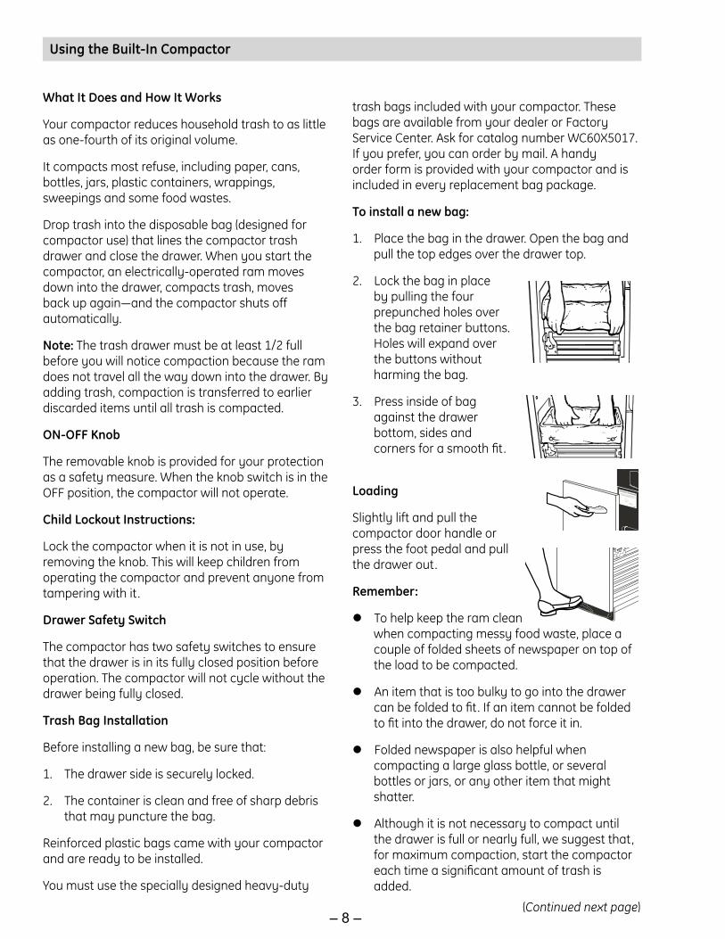
To install a new bag:
1. Place the bag in the drawer. Open the bag and pull the top edges over the drawer top.
2. Lock the bag in place by pulling the four prepunched holes over the bag retainer buttons. Holes will expand over the buttons without harming the bag.
3. Press inside of bag against the drawer bottom, sides and corners for a smooth fit.
Loading
Slightly lift and pull the compactor door handle or press the foot pedal and pull the drawer out.
Remember:
To help keep the ram clean when compacting messy food waste, place a couple of folded sheets of newspaper on top of the load to be compacted.
An item that is too bulky to go into the drawer can be folded to fit. If an item cannot be folded to fit into the drawer, do not force it in.
Folded newspaper is also helpful when compacting a large glass bottle, or several bottles or jars, or any other item that might shatter.
Although it is not necessary to compact until the drawer is full or nearly full, we suggest that, for maximum compaction, start the compactor each time a significant amount of trash is added.
Using the Built-In Compactor
(Continued next page)
– 9 –
Compacting
To start the compactor:
1. Turn the knob to ON.
2. Make sure the drawer is fully closed.
3. Lift the foot pedal up to start cycle.
The ram travels downward into the drawer, compacting the trash. At the bottom of the stroke, the ram automatically reverses direction, retracts from the drawer, returns to its starting position, and the compactor shuts off automatically.
The cycle takes less than 30 seconds. As the trash drawer fills with trash, cycle time gets progressively shorter.
WARNING: When bottles and cans are compacted, small tears in the bag may occur. This is normal and in no way affects the performance of the compactor. Keep the bag away from your body to prevent injury from sharp objects that may have pierced the bag.
Caution: Do not apply too much force when turning the knob. The knob should always rotate easily. Forcing may break the knob and damage the switch.
When emptying waste baskets into the trash drawer, some items may spill into the compactor behind the drawer. Items behind the drawer could prevent it from closing completely and prevent the compactor from operating. To remove such items from behind the drawer, open the drawer and remove it to clean them out. See the Care and Cleaning section.
Notes: You will not see compacting of trash the first few times you load. The compactor drawer should be about 1/2 full before the compactor can begin to compress the load.
Glass bottles can make a loud noise when they break during compaction. This is normal. Also, bottles in the trash drawer will not always break during the first cycle. Breaking glass and associated noise may occur several cycles later, depending on the type and volume of the trash.
To stop the compactor:
The compactor may be stopped at any time.
1. Attempting to open the drawer while the ram is moving will stop the ram. The safety switch will activate.
2. Close the drawer completely and the ram will travel back to the UP position.
3. Open the drawer fully and turn the knob to OFF.
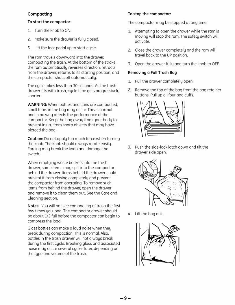
Removing a Full Trash Bag
1. Pull the drawer completely open.
2. Remove the top of the bag from the bag retainer buttons. Pull up all four bag cuffs.
3. Push the side-lock latch down and tilt the drawer side open.
4. Lift the bag out.

– 10 –
As is true of most appliances, proper care is needed to give you continued satisfaction. Before cleaning the compactor, turn the knob to the OFF position and remove it. If you will be away for more than a couple of days, remove the compactor bag. Lock the compactor by removing the knob and store it in a safe place.
Cleaning the Unit
To clean the outside:Wipe with a clean damp cloth.
Painted panels:Apply a coat of kitchen/appliance wax when the compactor is new, and then several times a year.
Stainless steel panels:Stainless steel panels can be cleaned with Cerama Bryte® or a similar product using a clean, soft cloth.Cerama Bryte is available from GE Parts by calling 800.626.2002 (U.S.) or 800.661.1616 (Canada).
To clean the drawer interior:
1. Remove the bag. (See Removing a Full Trash Bag.)
2. Wear protective gloves. There may be bits of glass in the drawer. Press the side door latch down.
3. Hold the side door latch and tilt the side of the drawer until the latch clears the drawer front. The drawer side can be removed by tilting and sliding it out.
4. Wash with a damp cloth using warm, soapy water. Rinse and then dry with a soft cloth.
5. If the drawer side was removed, slide it back into the tilted position.
6. Press the side door latch down while pressing the side to the upright position. Lock the side door latch.
To clean the cabinet interior:
1. Pull the drawer out until it stops. Note the tracks in which the drawer rollers move.
Caution: The drawer can scratch a finished floor. Place the drawer on a protected surface.
2. Lift the front to clear the drawer stops. Grab the drawer on both sides. Pull it out the rest of the way and set it aside.
3. Vacuum inside of the cabinet. Liquid spills or wet trash should be cleaned up by hand, or use a vacuum designed to pick up liquid.
4. Wash, rinse and dry the inside.
Care and Cleaning of the Built-In Compactor

– 11 –
15-in. Built-In Compactor
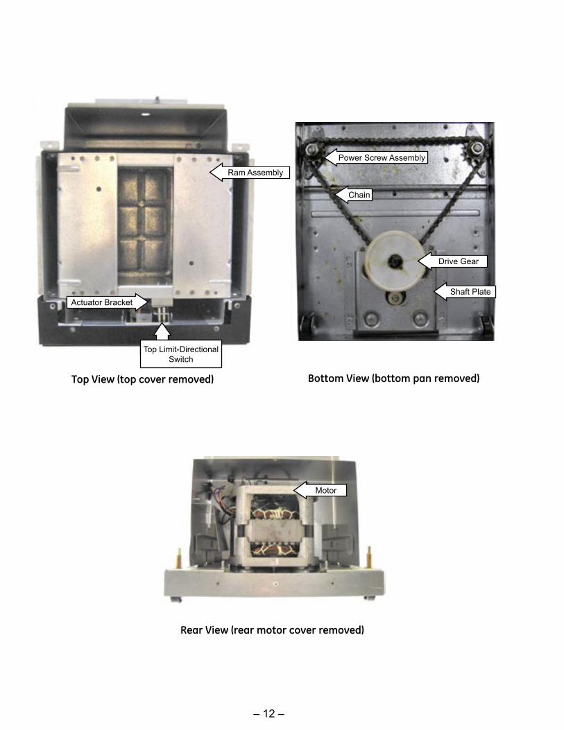
Component Locator Views
(Continued next page)
– 12 –
Top View (top cover removed) Bottom View (bottom pan removed)
Rear View (rear motor cover removed)
Actuator BracketShaft Plate
Power Screw Assembly
Ram Assembly
Drive Gear
Motor
Chain
Top Limit-Directional Switch

– 13 –
Built-In Compactor Components
Control Panel
To remove the control panel:
1. Open the compactor drawer. Turn the knob to the off position and remove it by pulling straight out.
2. Remove the 2 Phillips-head screws from the knob recess.
Switch Bracket
To remove the switch bracket:
Disconnect power.
Remove the control panel. (See Control Panel.)
Remove the 3 Phillips-head screws that attach the switch bracket to the frame.
1.
2.
3.
Insert a small-bladed screwdriver between the top of the control panel and the front cover.
Pry the control panel forward and release it from the 3 top tabs.
3.
4.
Lift the control panel from the 3 bottom tabs. 5.
Raise the switch wiring harness parallel to the bottom of the switch bracket.
4.
Pull the bottom of the switch bracket out to clear the bottom of the front cover opening. Rotate it approximately 45° counterclockwise then remove the switch bracket from the front cover opening.
5.
Switch Wire Harness
Switch Bracket
(Continued next page)

– 14 –
Top Limit Switch
Note: Disconnect power to the compactor before accessing the top limit switch.
The top limit switch is located on the switch bracket. It is necessary to remove the switch bracket and the ON-OFF switch to access the top limit switch. (See Switch Bracket and ON-OFF Switch.) The top limit switch is positioned on the right side of the directional switch, furthest from the ON-OFF switch. It is connected with blue and brown wires. Both switches are attached to the inside of the switch bracket with 2 Phillips-head screws.
Directional Switch
Note: Disconnect power to the compactor before accessing the directional switch.
The directional switch is located on the switch bracket. It is necessary to remove the switch bracket and the ON-OFF switch to access the directional switch. (See Switch Bracket and ON-OFF Switch.) The directional switch is positioned on the left side of the top limit switch, closest to the ON-OFF switch. It is connected with blue, yellow, and red wires. Both switches are attached to the inside of the switch bracket with 2 Phillips-head screws.
Caution: Ensure the switch bracket is installed with the switch arms resting in front of the switch actuator bracket. Damage to the top limit and/or directional switch will occur if the switch arms are positioned below the switch actuator bracket.
Actuator Bracket
Switch Arms
Knurl-Nut
ON-OFF Switch
Note: Disconnect power to the compactor before accessing the ON-OFF switch.
The ON-OFF switch is attached to the front of the switch bracket with a knurl-nut. It is necessary to remove the switch bracket to access the ON-OFF switch. (See Switch Bracket.) Use a pair of pliers to remove the knurl-nut. The switch can then be pulled off the bracket and the 2 wire leads disconnected.

– 15 –
Start Switch
Note: Disconnect power to the compactor before accessing the start switch.
The start switch is located in the front of the compactor on the lower right side. The start switch is secured in the front cover with locking tabs located on the top and bottom of the switch. It is necessary to use a small flat blade screwdriver to press and release the locking tabs.
Tilt Switch
Note: Disconnect power to the compactor before accessing the tilt switch.
The tilt switch is located in the front of the compactor above the drawer opening. The tilt switch is secured in the front cover with a locking tab located on the right side of the switch. It is necessary to use a small flat blade screwdriver to press and release the locking tab.
The switch can then be pulled out and the 2 wire leads disconnected.
The switch can then be pulled out and the 2 wire leads disconnected.
Start Switch Tilt Switch

– 16 –
Tilt Switch (Drawer)
Note: Disconnect power to the compactor before accessing the tilt switch (drawer).
The tilt switch (drawer) is located inside the cabinet on the right side wall. The tilt switch (drawer) is secured in the wall with a locking tab located on the bottom of the switch. It is necessary to use a small flat blade screwdriver to press and release the locking tab.
The switch can then be pulled out and the 2 wire leads disconnected.
Tilt Switch
(Drawer)
Top Cover Panel
Note: To access the top cover panel, the compactor must be removed from installation.
The top cover panel is attached to the frame with 6 Phillips-head screws.
After removal of the 6 screws, the top cover can be slid to the rear and removed.

– 17 –
Motor Assembly
Note: To access the motor assembly, the compactor must be removed from installation.
Remove the 2 Phillips-head screws and the side track shield from the motor cover.
Disconnect the motor wire harness and the black neutral wire from the motor (protector).
3.
4.
Motor Wire Harness
Neutral Wire
Track Shield
Place the compactor on a protected surface and stand the compactor on its top.
Remove the 3 Phillips-head screws and the bottom pan from the frame.
5.
6.
Bottom Pan
(Continued next page)
To remove the motor assembly:
Disconnect power and remove the drawer.
Remove the 3 Phillips-head screws and the rear motor cover from the frame.
1.
2.
Motor
Motor GearGear Pin
Ring Clip
Sprocket
Drive Gear
Chain
Teflon Washer
Wave Washer
Shaft Plate
Washer

– 18 –
Remove the four 3/8-in. bolts that attach the motor assembly to the frame.
Slide the motor assembly towards the front to loosen the chain.
7.
8.
Using a flat-blade screwdriver, pry off the clip ring and remove the metal washer and drive gear with sprocket from the shaft plate.
9.
Carefully lift the motor assembly from the frame.
10.
Metal Washer Clip Ring
Drive Gear
Place the motor on it's side and support the motor gear with a piece of ¾-in. wood.
Use a 3/16-in. punch to drive the slotted pin from the motor gear, then slide the gear off the motor shaft.
4.
5.
Shaft Plate
Motor Gear
To replace the motor:
Place the motor assembly on a protected surface.
Mark the position of the motor on the shaft plate.
Remove the four 7/16-in. nuts and the shaft plate from the motor.
1.
2.
3.

– 19 –
Ram Assembly
Note: To access the ram assembly, the compactor must be removed from installation.
To remove the ram assembly:
Remove the top cover. (See Top Cover.)
Plug in compactor, turn ON-OFF switch to the ON position, and close the drawer.
Note: The ram is in the normal stop position, approximately ¾ inch recessed from top of frame.
1.
2.
Lift the foot kick, then release to start down travel of the ram.
After the ram reverses and begins up travel, lift and maintain the foot kick in the lifted position until the ram runs off the top of the power screw assemblies.
Note: The ram is now in an over stop position, approximately flush with top of frame. A repetitive thumping sound will be heard.
3.
4.
¾-in. Recess
Flush
Ram Assembly
Frame
Frame
Ram Assembly
Disconnect power.
Remove the switch bracket. (See Switch Bracket.)
Lift and remove the ram assembly from the top of the power screws.
5.
6.
7.
Actuator Bracket
Switch Arms
(Continued next page)
To replace the ram assembly:
Note: Be sure to position the actuator bracket at the front of the compactor.
1. Lower the ram assembly to rest on top of the power screw assemblies.
Caution: Insure the switch bracket is installed with the switch arms resting in front of the switch actuator bracket. Damage to the top limit and/or directional switch will occur if switch arms are positioned below the switch actuator bracket.
2. Replace the switch bracket. (See Switch Bracket.)

– 20 –
Ram Slides
A ram slide is located on each vertical flange of the ram (2 on each side). Each vertical flange has 2 tabs that hold each ram slide. Each ram slide is inserted under the tabs.
Power Screw Nut
A power screw nut is attached to the bottom of each side of the ram. It is necessary to use a small flat-blade screwdriver to remove the retaining clip and pin that hold each power screw nut to the ram.
Caution: Discard the removed retaining clips and pins. Use the new retaining clips and pins included with the replacement power screw nut assembly.
Power Screw Nut
Pin
Clip
TabSlide
Power Screw Nut
Connect power and check operation of ram before installing top cover.
3.
– 21 –
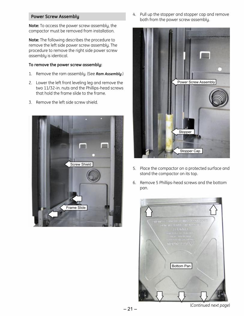
Power Screw Assembly
Note: To access the power screw assembly, the compactor must be removed from installation.
Note: The following describes the procedure to remove the left side power screw assembly. The procedure to remove the right side power screw assembly is identical.
To remove the power screw assembly:
Remove the ram assembly. (See Ram Assembly.)
Lower the left front leveling leg and remove the two 11/32-in. nuts and the Phillips-head screws that hold the frame slide to the frame.
Remove the left side screw shield.
1.
2.
3.
Frame Slide
Screw Shield
Pull up the stopper and stopper cap and remove both from the power screw assembly.
4.
Place the compactor on a protected surface and stand the compactor on its top.
Remove 5 Phillips-head screws and the bottom pan.
5.
6.
Stopper Cap
Stopper
Bottom Pan
Power Screw Assembly
(Continued next page)

– 22 –
Loosen the four 3/8-in. bolts that attach the motor assembly to the frame. (See Motor Assembly.)
Slide the motor assembly towards the front to loosen the chain.
Using a flat-blade screwdriver, pry off the clip ring and remove the metal washer and drive gear with sprocket from the shaft plate. (See Motor Assembly.)
Remove the two 3/8-in. bolts that attach the power screw assembly to the frame.
Partially raise the power screw assembly and remove the chain from the sprocket.
Lift the power screw assembly from the frame.
7.
8.
9.
10.
11.
12.
Power Screw Assembly
Frame
Sprocket
Chain
Note: To access the chain, the compactor must be removed from installation.
To remove the chain:
Remove the ram assembly. (See Ram Assembly.)
Place the compactor on a protected surface and stand the compactor on it's top.
Remove the 5 Phillips-head screws and the bottom pan from the frame.
Loosen the four 3/8-in. bolts that attach the motor assembly to the frame. (See Motor Assembly.)
Slide the motor assembly towards the front to loosen the chain.
Using a flat-blade screwdriver, pry off the clip ring and remove the metal washer and drive gear with sprocket from the shaft plate. (See Motor Assembly.)
Remove the two 3/8-in. bolts that attach each power screw assembly to the frame.
Partially raise each power screw assembly and remove the chain from each sprocket.
1.
2.
3.
4.
5.
6.
7.
8.
Frame
Power Screw Assembly
Sprocket

– 23 –
Diagnostics and Service Information
The following checks can be made by removing the control panel:
Motor Start Windings
Remove the red and yellow wires from the directional switch and connect an ohmmeter to the wires. Ohmmeter should read 3.4 to 4.6 ohms.
If the ohmmeter shows an open circuit, the start windings are open and the motor must be replaced, or the yellow or red wire is broken or disconnected at the motor.
Tilt Switch (drawer)
Remove the wires from the tilt switch (drawer) and connect an ohmmeter between the two terminals. Refer to the wire schematic for the position of the switch contacts.
Move the drawer in, the switch is closed. Move the drawer out, the switch is open.
Tilt Switch
Remove the black wire from the tilt switch. Remove the orange wire from ON-OFF switch. Connect an ohmmeter to the black wire and orange wire. Press and release switch several times.
Press the switch, and the switch is closed. Release the switch, and the switch is open.
On-Off Switch, Top Limit-Directional Switch
To test each switch, remove the wires from the switch and connect an ohmmeter between the two terminals. Refer to the wire schematic for position of the switch contacts.
Motor Run Winding
1. Remove the blue wire from the start switch, and the blue wires from the top limit switch and the directional switch.
2. Connect an ohmmeter to the blue wire and to the neutral side of the power cord.
3. An accurate ohmmeter should read about 1.2-1.6 ohms.
Motor Centrifugal Switch
1. Disconnect the wires from the motor centrifugal switch.
2. Connect an ohmmeter to terminals.
3. The ohmmeter should read 1 ohm or less. If the circuit is open, the motor switch is stuck or burned. Motor must be replaced.
PROBLEM CAUSE
Unit Dead Not plugged in No power to the outlet Tilt switch (drawer) contacts open Tilt switch contacts open Motor windings open ON-OFF switch contacts open
Unit won't keep running
Top limit switch contacts open Centrifugal switch contacts open
Unit doesn't stop Start switch contacts fused Top limit switch "on" Out of adjustment (Switch arm
deformed) Contacts fused
Unit oscillates up and down
Motor centrifugal switch contacts fused
Unit makes humming noise
Mechanical jam Start winding not energized Winding open Motor centrifugal switch contacts
open Run winding open
Electrical Troubleshooting Guide
COMPACTOR CYCLEStart* Downward
TravelReverse
(Stall)Upward Travel
End of Cycle**
Red - Blue
Yellow - Blue
*First 3/4" (19 mm) of downward travel = Closed**Last 3/4" (19 mm) of upward travel
Directional Switch Chart
(Continued next page)

– 24 –
Jammed Ram
1. Check for 120 Volts at the outlet.
2. If drawer is open, push in on the drawer.
3. If ram does not come up, unplug the unit.
1) Open motor rear cover plate.
2) Rotate the motor shaft in the counter- clockwise direction, using 1/4” hex socket screw key to make the ram go up.
Chain Adjustment
There should be 3/8” (9.5mm) to 1/2” (12.7mm) deflection between any 2 sprockets.
Lubrication
Power Screws - If needed, apply WC32X5004 grease to the Ram Screws.
Drawer Slide Rollers - Apply WC01X10006 oil.
“Not Compacting” Complaints
Low Voltage - Check supply voltage with the ram compacting trash. At 120 volts ram force is approximately 2300 lbs. At voltage lower than 120 volts ram force is reduced.
Ram Travel - Ram stops 7-1/2” (190mm) above bottom of container. No noticeable compaction will occur until container is 1/2 full.
Note: For best compacting results, do not overload the compactor container. Cycle the unit frequently. No compaction will occur if too much trash (bottles, cans, etc.) is added at one time. Overloading may exceed the crushing force of the ram. A spongy trash load may prevent bottles from breaking. Most, but not all, bottles in a trash load will be broken.
– 25 –
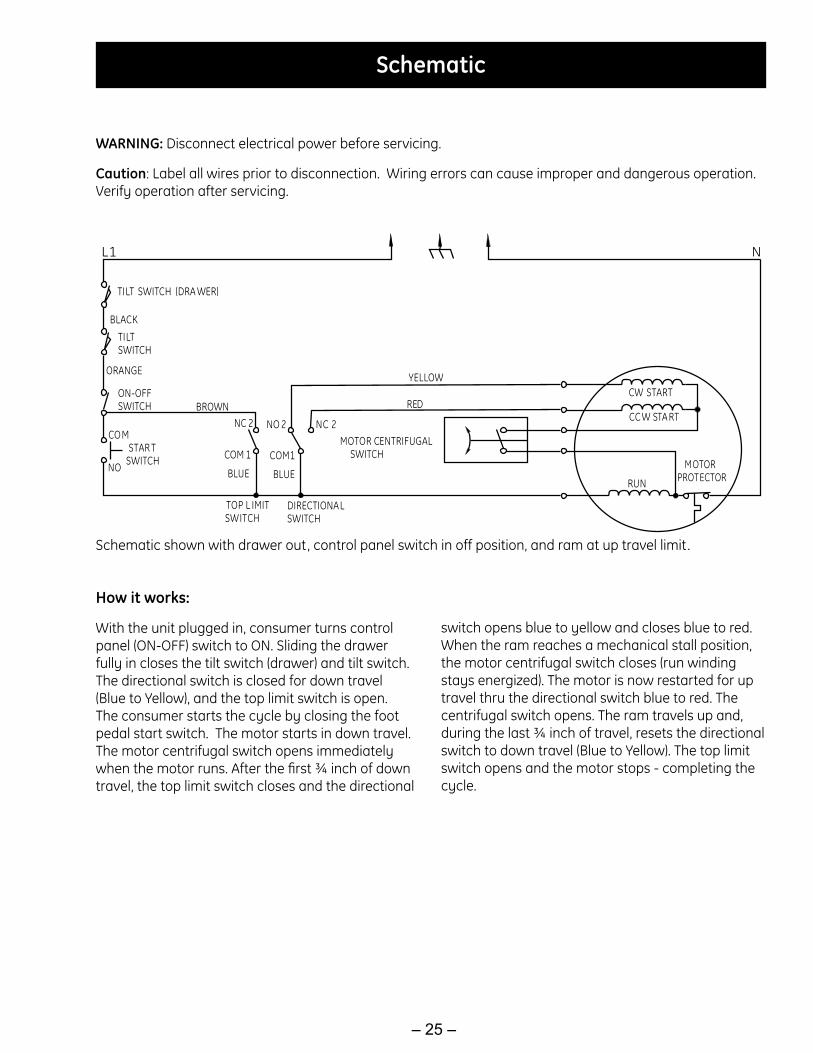
WARNING: Disconnect electrical power before servicing.
Caution: Label all wires prior to disconnection. Wiring errors can cause improper and dangerous operation. Verify operation after servicing.
Schematic
NL1
TILT SWITCH (DRA WER)
BLACKTILTSWITCH
ORANGE
ON-OFFSWITCH
COM
NO
STAR TSWITCH
BROWN
C
NC 2 NO 2 NC 2
OM 1
BLUE
TOP L IMITSWITCH
DIRECTIONALSWITCH
MOTOR CENTRIFUGALSWITCHCOM1
BLUE
CW START
CC W STA RT
RUN
MOTORPROTECTOR
YELLOW
RED
Schematic shown with drawer out, control panel switch in off position, and ram at up travel limit.
How it works:
With the unit plugged in, consumer turns control panel (ON-OFF) switch to ON. Sliding the drawer fully in closes the tilt switch (drawer) and tilt switch. The directional switch is closed for down travel (Blue to Yellow), and the top limit switch is open. The consumer starts the cycle by closing the foot pedal start switch. The motor starts in down travel. The motor centrifugal switch opens immediately when the motor runs. After the first ¾ inch of down travel, the top limit switch closes and the directional
switch opens blue to yellow and closes blue to red. When the ram reaches a mechanical stall position, the motor centrifugal switch closes (run winding stays energized). The motor is now restarted for up travel thru the directional switch blue to red. The centrifugal switch opens. The ram travels up and, during the last ¾ inch of travel, resets the directional switch to down travel (Blue to Yellow). The top limit switch opens and the motor stops - completing the cycle.

– 26 –
Warranty