ge digital energy power quality - ge industrial...
TRANSCRIPT
GE Digital EnergyPower Quality
IntroductionVoltage spikes and surges from both external and internalsources can cause damage to all electronics anddirectly affect the performance and life expectancyof connected equipment. From electronic lightingballasts to computer servers, if there is a printed circuitboard inside, it is susceptible to transient voltagesurge damage. As microprocessors and componentsthat make up this equipment grow smaller and fasterwith each new generation, their susceptibility to transientvoltage surge damage becomes ever greater.
The TR5000 series is ideal for both new and retrofitcommercial and industrial applications where basicmonitoring is required and performance cannot becompromised. Available in ratings from 25kA - 100kAper mode, (50kA - 200kA per phase) the TR5000 seriesis the perfect surge suppression product for protectingyour critical sensitive electronic equipment throughoutyour facility.
Recommended installation locations are primary andsecondary distribution and point of use levels. Designedfor distribution and point of use locations but rated forservice entrance, the TR5000 series has been third-party tested to ANSI/IEEE C3 (10kA 8 x 20μs) impulses.The entire TR5000 line-up has been engineered to thehighest standards and is designed for rigorous dutyand long life as evidenced in our outstanding minimumrepetitive surge current capacity test results.
Features and Benefits> The TR5000 provides maximum surge protection
with outstanding clamping characteristics formedium and low exposure locations through the use of industrial grade MOV architecture.
> UL 1449 3rd Edition, Type 2> Third-party tested per IEEE C62.62 and NEMA LS-1
for the rated 8x20μs surge current, per mode withfusing included.
> Maximum installation flexibility is achieved in theTR5000 through its high surge suppression ratings tosmall footprint size ratio.
> Fast rise-times, high frequency transients andelectrical line noise are reduced with standardEMI / RFI filtering technology on 65, 80 and 100kAper mode products (Not applicable for 25 and 50kA)
> 10 modes of protection (L-N, L-G, N-G, L-L)> Green phase protection status LEDs> NO/NC Form C Dry Contacts for remote monitoring> Patented thermal fuse technology > Standard heavy gauge painted steel NEMA 12
construction, available in surface or flushmount> Durable fiberglass construction for NEMA 4X> 5 year limited warranty (standard),
10 year limited warranty (optional)
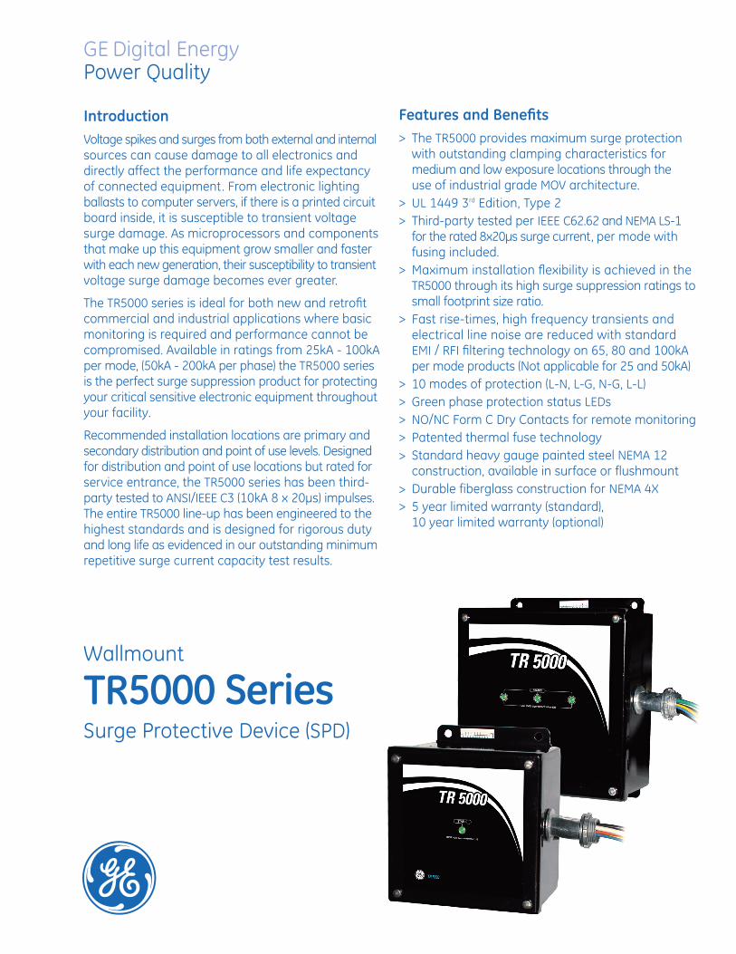
Wallmount
TR5000 SeriesSurge Protective Device (SPD)
DEA-367 • Page 2
Applications> Distribution Equipment
> Branch Panel
> Point of Use
> New Construction and Retrofits
> System Expansions
Standards> UL 1449 3rd Edition, Type 2
> UL 1283, EMI/RFI noise filter (only 65, 80, 100kA)
> UL 96A, Lightning Protection System(only 65kA - 100kA models can be used in UL 96ALightning Protection Systems)
> ANSI/IEEE C62.41 - ANSI/IEEE C62.45
> IEEE C62.62
> cUL, CSA C22.2
> NEMA LS-1 - 1992 (R2000)
> MIL-STD-220B
> ANSI/NFPA 70 (Article 285)
Technical Specifications
Nominal Discharge Current (In)25kA - 50kA rated units: 10kA65kA - 100kA rated units: 20kA
Short Circuit Current Rating (SCCR)65kA (30A breaker required)
Operating Frequency50/60 Hz
Connection10 AWG Pre-wired Conductors, Parallel Connected
Operating Temperature-40° F to 149° F (-40° C to +65° C)
Operating Humidity NEMA 12 0% to 95%NEMA 4X Non-Condensing 0% to 100%
Weight25-50kA 11.7 lbs. (5.31 kg)65-100kA 19.7 lbs. (8.94 kg)
[19.05]3/4" N.P.T.
[19.05]3/4" N.P.T.
4.00[101.6]
6.25[158.75]
6.00[152.4]
4.37[111.0]
4.37[111.0]
8.00[203.2]
6.00[152.4]
8.25[209.55]
2.85[72.39]
2.85[72.39]
1.55[39.37]
1.55[39.37]6.25
[158.75]
6.75[171.45]
7.50[190.5]
9.55[242.57]
8.25[209.55]
8.75[222.25]
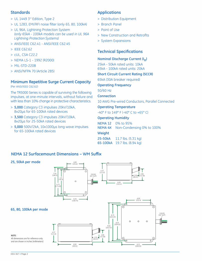
NEMA 12 Surfacemount Dimensions – WM Suffix
Minimum Repetitive Surge Current Capacity (Per ANSI/IEEE C62.62)
The TR5000 Series is capable of surviving the followingimpulses, at one-minute intervals, without failure andwith less than 10% change in protective characteristics.
> 5,000 Category C3 impulses 20kV/10kA, 8x20μs for 65-100kA rated devices
> 3,500 Category C3 impulses 20kV/10kA, 8x20μs for 25-50kA rated devices
> 5,000 500V/2kA, 10x1000μs long wave impulses for 65-100kA rated devices
25, 50kA per mode
65, 80, 100kA per mode
NOTE:All dimensions are for reference only and are shown in Inches [millimeters]

Page 3 • DEA-367
EnclosureDescription Suffix* NEMA
Painted Steel 12
F Painted Steel 12
Fiberglass 4X
Mounting
Surface
Flush
Surface4
NominalVoltage
(Volts RMS)
System Voltage
Configuration
MCOV %Max.
ContinuousOperating
Voltage
120S 120/240 1 Ph, 3 W + G 150V
120Y 120Y/208 3 Ph, 4 W + G 150V
220/380 3 Ph, 4 W + G 320V
277Y 277Y/480 3 Ph, 4 W + G 320V
240Y 240/415 3 Ph, 4 W + G 320V
240D 240 Delta 3 Ph, 3 W 270V
480D 480 Delta 3 Ph, 3 W 550V
240H 120/240 Delta HL 3 Ph, 4 W + G
Catalog # _ _ _ _ _ _ _ _ _ _ _ _ _T R 5 WM
220Y
Maximum Surge Current Capacity
Per Mode Per Phase
25kA 50kA
50kA 100kA
65kA 130kA
80kA 160kA
100kA 200kA
025
050
065
080
100
A
B
B
B
B
C
D
* All suffix features are mutually exclusive
Phase Rating = (L-N + L-G)
Note: 150V (L-N/G) Phase A&C; 270V (L-N-G) Phase B
Catalog # example: TR5277Y100WM— 277Y/480 V, 3 Ph, 4W + G— 100kA per mode— NEMA 12, surface mount
SourceConfig-uration
Voltage Code 120S / 120Y 240D 240H 220Y / 240Y / 277Y 480D
Protection Mode L-N L-G N-G L-L L-G L-L L-N HL-N L-G HL-G N-G L-L HL-L L-N L-G N-G L-L L-G L-L
UL 1449, 3rd Edition Voltage Protection Ratings (VPR)(assigned UL rating)
900 1000 900 1500 1500 2000 900 1500 1000 1500 900 1500 2500 1500 1500 1500 2500 1800 4000
UL 1449, 2nd Edition Suppression Voltage Ratings (SVR)(assigned UL rating) *
400 400 400 — 700 — 400 700 400 700 400 — — 900 800 1500 — 1500 —
* NOTE: SVR Ratings are no longer assigned by UL and are included in the table above for reference purposes only.
065, 080 & 100kA Protection Ratings
Voltage Code 120S / 120Y 240D 240H 220Y / 240Y / 277Y 480D
Protection Mode L-N L-G N-G L-L L-G L-L L-N HL-N L-G HL-G N-G L-L HL-L L-N L-G N-G L-L L-G L-L
UL 1449, 3rd Edition Voltage Protection Ratings (VPR)(assigned UL rating)
600 600 600 1000 900 1800 600 1200 600 1000 600 1000 1800 1200 1000 1200 1800 1800 4000
UL 1449, 2nd Edition Suppression Voltage Ratings (SVR)(assigned UL rating) *
500 500 500 — 800 — 500 800 500 800 500 — — 800 800 800 — 1500 —
025, 050kA Protection Ratings
L1
N
L2
L1
N
L2L3
L1
L2L3
L1
L2L3
L1
L2L3
N
A B C D E
Esee Note
Source Configuration Diagrams
DEA-367 (12/09)
GE Digital Energy – Power Quality830 W 40th Street, Chicago, IL 60609 USA800 637 1738 www.gepowerquality.com
Information subject to change without notice. Please verify all details with GE. © 2009 General Electric Company All Rights Reserved
Ø 0.4332 HOLES [11.00] 4 PLCS
A15.73[399.54]
13.30[337.8]
15.19[385.82]
6.50[165.1]
13.85[351.79] 4.00
[101.6]
11.01[279.65]
65, 80, 100kA per mode
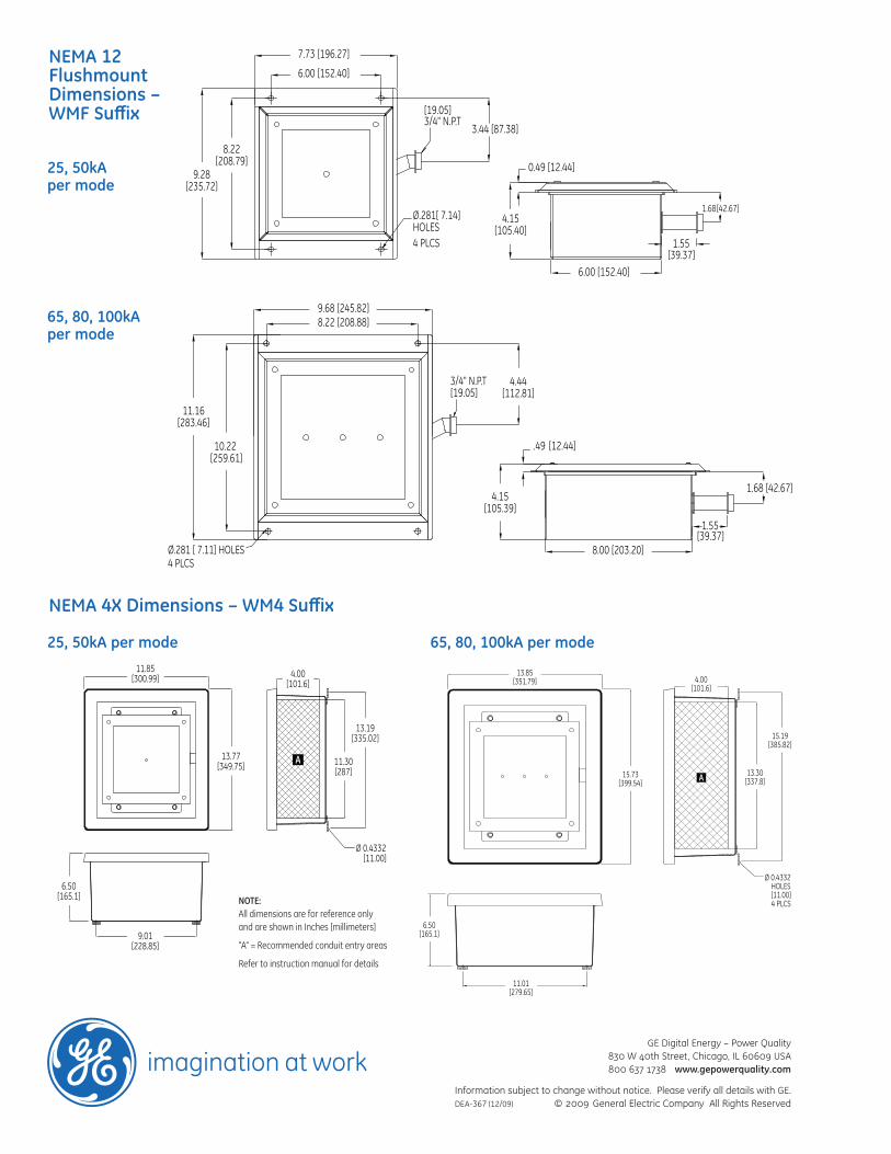
NEMA 4X Dimensions – WM4 Suffix
Ø 0.4332 [11.00]
11.85[300.99]
A
6.50[165.1]
9.01[228.85]
13.77[349.75]
13.19[335.02]
11.30[287]
4.00[101.6]
25, 50kA per mode
NEMA 12FlushmountDimensions –WMF Suffix
.49
Ø.281 [ 7.11] HOLES4 PLCS
1.68 [42.67]
1.55
3/4" N.P.T
[12.44]
[39.37]
[19.05]
11.16[283.46]
10.22 [259.61]
4.15[105.39]
8.00 [203.20]
8.22 [208.88]9.68 [245.82]
4.44[112.81]
65, 80, 100kAper mode
NOTE:All dimensions are for reference only and are shown in Inches [millimeters]
“A” = Recommended conduit entry areas
Refer to instruction manual for details
0.49 [12.44]
1.68Ø.281[ 7.14] HOLES4 PLCS 1.55
3.44 [87.38]3/4" N.P.T
[42.67]
[39.37]
[19.05]
6.00 [152.40]
7.73 [196.27]
6.00 [152.40]
9.28[235.72]
8.22[208.79]
4.15[105.40]
25, 50kAper mode