ge ,t6 1of - rasayani · the density of;{exeatic ball is 12000 t
TRANSCRIPT

\E-- Se-rnfl (CrVr 9 C' 8 ezs l{"r.i-Trrn q ''7e\6GE -T-
1of s{ ,t6
QP Code : 3{628
{3 Hours} tTotal Marks I 80
\ore l. Attempt any 4 out of six questions .-.*"2. Question I is compulsory \-i. Assume any suitable data where ever required ary
t\JQ.; Aitempt any four q\
a. What are the methods for improving the stabilify of slopes 0S)j.:1.\
b. A reaining wall 6m height with a smooth verticai back fill is pushed against soil mass 6-.!05trivine C+0l$ymz andl=150
-19ftI'{1m3. What is the tstal Rankine fassive pressuryg?'
if the horlaonial soil surface carries a load of 50 L.N/m' Wh"t is the poinq olF'-{'appticarion of resultant thrust
..,(r
,l)e. Explain tbe adv'antages of reinforced soil ,^f 05
_-.-"f. Explain the limitations of plate load test ,1f 05
Q.2 a- Explain the friction circle method for finding faoto, of safdffislopes ' 10
b. A section of canfilever retaiuing wall as *nl*n in dq;" back fill has C:0 +=410 t05l6kNlmr .water'table is eonsiderable depttr.lQ6{v ground surface. the Backfill 'carries a uniform surcharge load of 35ld-l/ry-hJ*ck the stabilify of retaining wallassume the mit weight of concrete is 24kN/p|{afe bearing capacity oisoil beiow thebase is 500kN/mr .1p"
'o-'
An4 ---?
ITUEN OVER
t+0,rl.i
e* -.dr-o(J
fm
QP Code : 3t 628
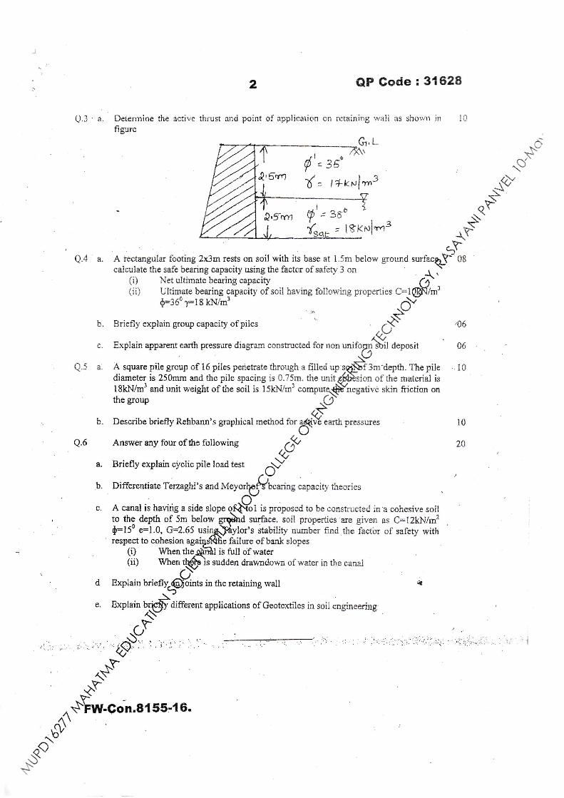
Q.3'a Deterrnine the active thrustfigure
G,L_
{'= e{{,5.r"1 { = l*rruf m3
Q,Srrrt
' l8t<ru1'ng
5rQ.4 a. A iectangular footing 2x3m rests on soil with its base at l.5m below ground ,urfu*qf OA
caiculate the safe bearing capacity using the factor of safety 3 on _r .-(, Net ultimate bearing capacity (4'(ii) Ultimate bearing capacity of soil having following propenies C=tN/mi
{:360 1:18 kN/# .\v-
b. Briefly explain group capacity of piies ""
.'$=" ,06
lyc. Explain apparent earth pressure diagram constructed for non uniforu sbi) deposit 06r\J
Q.-( a. A square piie group of 16 piles penehate through a filled up rq$f S* depth. The pile . 10diameter is 250mrn and the pile spacing is 0.75m. the unitp@sion of the material is18kN/m3 and unit weight ofthe soil is l5kl'I/rn3
"o*prtqQYoegative skin friction on
thegroup .(r'osb. Describe briefly Rehbann's graphicai method for a1Qivts earth pressures 10
Q.6 Answer any four of the following ,t9-tg r^
Differentiate Tbrzaghi's and
c- A canal is having a side sicpe I is proposed to be constructed ia a cohesive soilsurface. soil properties are given as C:12kN/m2
tor's stabilif.v number furd the factbr of safety with' respect to cohesion failure of ban-k slopes(i) When the is fulI ofwater
2
and point of application on retaining rvall as showu in l0
*c.ay*
(y-\-\
.-r{F
a.
b.
to the depth of 5m below
0=l50 e=I.0, G=2.65 usu-q
' -':i;11r::.r,;;i;t,. r.. i 'i,r :' i
*r^S
')\f>''
^ $FW-Con.8{ 55'{ 5',^( \
n_\
'tb'.A'$
*-Y
d Exolain
sudden drawnd.own of rvater in'rhe canai
in the retaining wall

-fE- Sewr[ CB & S. yl.^:- Jun{ 2916 Civr'\Sub - DOSSt6lsl te
Q"F. Code z 577401
i4 Hours) {TotalMark-80
N.B.- tl)Question No.1is compulsory. rC{2} Attempt any three out of remaining four questions- N
^bts{3} Assume suitable data wherever necessary. Use steel grade Fe 410. S}-tA) Use of tS-8ffi, lS€75 and steeltable is permltted during examination. ;|
o.q t
Design the typical principal rafter, main tie and an interrnediate strut fo(fE (32)
steel roof truss shown in figure. Use following data'
Centre to centre spacing of trusses= 4 m.
(-rTotal dead load on a truss 400 N per m2 of plan area. Live load as@r 15 875
lrfi-J laa-{ - 'f {nfl ft/*2 fe..^r!^- g. ^^,*ol 4a La*h clnno<} ^yffird load = 1100 N/m' {suction & normalto both slopes} /i's+'
Y
tl,4m
-L
{r
{Ljnit wt. 20 t't/mu}
+larr!a;.
oR nq. -
Figure shows the typical flasr plan of gtFel building. Design the beams 'Sr'
ani '82'. Top flanges of allthe bear"rla$/* *t the same level and embedded in
r-cncrete of 150 mm RCC slab. *QftIsign the connection between these two
t32)
beanrs using bolts of grade a.fuQse following data-
imcosed load = 3 KN/m2. FSS finlsh load = 1.5 KNlm?.
Ali beanrs support 150 E&ihick
brick wall, 3.5 m in height.
.g1*c' T.^.-i r r I
.,.."r' *.1 l*, 1,,, *.r*'llll,r-llll-':' !rI-C, -
$f t- ?'?5rr --F t.af,rr, **
b7\vr\\-'
T*rn Over
&-
Q.P. Code :577401
2
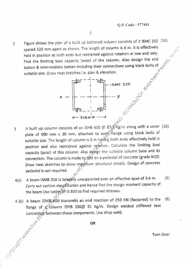
Figure shows the plan of a built up battened column consists of 2 lsMC 350 {16}
spaced 320 mm apart as shown. The lenglh of column is 8 m. it is effectively
held in pcsition at botl'i ends but restrai*ed against rotatio* at cne end only' ^ o'\"
Find the limiting I*acI capacity (axiai) of the colt'lmn. Also design the end z)", rr -r .-\"
hatt*n & interrnediate batten including their csnnections using black bolts of Sl.-*-\suitahle size. Draw neat sketches i.e. plan & elevatlon.
rs*4c 351)
x
d-s
r\\:'. v-t-\-'
^+-i A huilt up cohirnn consists of an |SHB 450 S 8it.{Fg/m along witfr a csver i16i
plate of 400 mm x ?S rfim, attached te ear<$$lange using black bolts *f
suitable size" The length of column is 5 m k6u b*th ends effectively held lt''t
posirion a*d alsc restrained against tq;Qlion. Calculate ihe limiting load
capacity (axial) of this column. also $fgn the suitable colurnn base and its
connectio*. Tl"ic coiurnn ir made to.G\i an a pedestal of ccncrete {grade M20'
Draw neat sketches t+ show *pHum structurai details. Design of co*crett
pedestal is not required. +X4ta) A bearn ISMB 350 is tatE#V unsupported over an effective spnn of 3'5 m' {8}
Carry out section clag$ffr*tion and hence find the deslgn mornent capacity of
the beam Us* tabiqffi lS 800 to find required stres$es.
c--4 (h) A beam rsrvrffio *ansmits an end reactio* of 250 KN {factored} to the {8}
fiange of _S\"olumn ISHB 250@ 51 Kelm. Design welded stlffened seat
.oonu.q&Lu,*uun these cornponents, Use shop weld'{i(?"
-f1Y
-v-.a'H'
1-\$
A/\\r\\^rb"
ow.\.:j
Turn Over
\Q
4 ib)
Q.P. C*eIe :577401
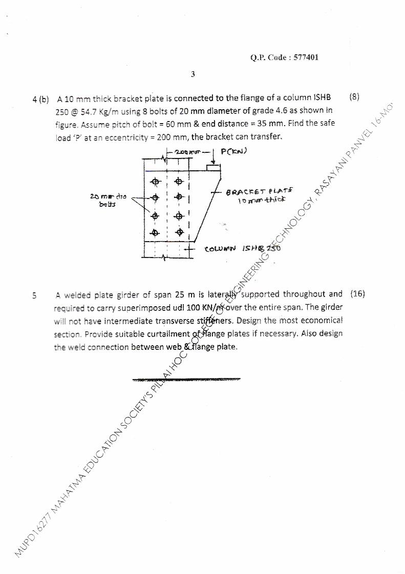
A 1S mrn thick bracket piate is connected ta tha flange +f a colurn* ISHB {8}
250 €) 5a,7 Kg,/m using I bolts of 20 mm diameter of grade 4,6 as shown in -:-3
figure. Ass1in1e pitch of bolt = 60 mm & end distance * 35 mm. Find the safe {{"load'F et an eccentricity = 2ffi mm, the bracket can transfer' Sry
?.$rmrr* t F(!rt'r)+,(ral)
*qY-
$"-(-- \
8*Ac.FEr r LArr q-YJzs*rdia{+ i+t f eT,.ffitf'^d'
o1 ..s"
t6tl)vrr,J *tr*gs'(q
zr\',\L
,v,..(/,.S
A welded piate girder af span 25 rn is later$/i'upported thr*ughout and {16}
requined to carry suoer[mposed udl 100 Xfrf/$i'v*r the entire span. The girder
rviil not have intermediate transverse stiffrrers, Design the most economical
section. Proyide suitabfe curtailmentg{ffange plates if necessary. AIso designIJ
tiTe weid ccnnection between web_&JIange plate.
.o"rav\'
- q\*.(-
l'/,\'.V
.o'^s..LJ
,.l'\L/
^\)a/tsx
NN-;r{
"^\1t\An\n\
^6v.€'Ns
l+I+lf
;+i+
++t+
I
t
It
I
AZ
,Il
;err\ E c6crr l_"YD {{t1 {qtrQ- &c 1b
tratr
( 3 Hours)
\.8. : 1) Question numtrer one is :o1p:ltotl ^,,^.2) Attempt any three of remaining five quesltons'
3) Assume suitable data if required'
4) Drar'l neat sketches rvherever Eecessary'
1 . So1r,e an1'four olthe foliorn'ing: . r ^i * ^^*i^rrc {tA) Enlist * t*pf*it' factors lffecfinS
design periods' -.rY-
B) \tr-hat u'"'t"t-thu'acteristics of hazardous wastes? +f
C) ExplainBt;p"*tof chlorination' I
D)Statethef*o"affectingto"uiio'oflntakeStructure'(i'E) Explain Dead End & Radial rrrffir";;';; distribution *ttp@:ketches'
2. A) Design a rectangular sedimentation tank to tteat2MlD ssuttt' Assume 10
detenticn time of 3Hrs. * now tifough velocity of 7'5 e1fu"*i"' if the depth
of tank is 3m, {ind the o'*'flo* 'xeldimensions g(tfle tank'
B) Differentiate befween Rapid 'uJ g''u'lty filter &&Yw sard filters 6
c) Describe wirhneat sketch d;;r?;;g orpr.rggf't'"t' 4
.+c-
3. A) whar is leachate? How leachate i, ,oxd'o in the iandfill site? Explain ls
B) Htff,T::lr::'*, methods oraisinsfo-n & irs suitabilitv. 10
, ffiution of 1,00,000 which is to be Served 10
by a 200 lit/head/day waterp$pply'
B) Explain ;:1,r"-,;@i*, uiotogi.al characteristics of water' write 10
the standards for Potah{fiiater'
.-q* ---r+1- *o,rr cl-efnh 10' \ ith neat sketch' I u
j -\) Define rvateruo@t''tg' Explain i::1t::1":,t1,I",.,^,n anv one in detail. 5;l illl"#:Trffi::;;""il-'"':';':::'^'::.::*:il'Yoneindetail :Ci ShortlY tlr" rrr..h*ism of floccrrlation & coagr.r1ation^
,-_,t 20
6. \tr'rite shoS\rLdte on following (Any four)
D -($ources of solid waste'
.p$ R"*oval of lron & Maganese'
oh) Tube settler
<S ttf water bome diseases'
+f U Appurteaances in distribution system'v-
+/,, ',^.^.\
^..tuoQ\)\-'s
bllbQP Code 577700
I Total Marks : 80
'!-
t)s
vN(]\\

'aL /e#G',l I se44 v]- cnus f l4"q 4ona 2P t b
9"b' 4r-r-E %loal e-a u'
QF Gode I 3{&55-1-
(3 hours) ,i*-'Note: Mar Marks: 80
^ay"V1. Questionno.l is compulsorY ,<;,2. Solve any3 questions outofremainiug ,$3. Ass:me data wherever mcesstry and clearly mention &e assumptiors made. Oq'4. Draw neat figuros as required. {fl
Q-1 Solveany four *bf 20
Q-\a) Define specific force md explaiu specific force curve in detail.
,;\ ,t
b) Erylain 51, 52, 53 profile in detail with neat sketch. C)'J,-\r-
c) Whatarethe defects in l,acey's theory? i. .+V-+'
d) Ditrere,ttiate between streamlined body and bluffbody. {ye) How will you detemine whether a boundary layer flow is aq5$fi flow, detached flow or
m&e verge cf se,parartion ,rS'eJ a) Assmine ihat the veloc$ disribution in E5$fuarv hyer is glYetr by 10
?(rf ''calculce T,3 * f. ,r u, u ""*rb=Y*on,
free srerm velocitv v was
observed b be 10 m/s and the thickness of lh6)iundary layer as 25 mm" tlen calculate
tre euergr loss per tmit length due to thE(fffoanon of bouadary layer. Take P = 1.226;''^'-- *T-b) DeriveVonKarman's momerltumrdd Eguation' 10
^{)e j a) A cy,linder 1.2 m in aiameteri@Jated about its axis ln air having a velocity of 128 km
per hour. A lift of 5886 Ngp\'meter length of the eylind.er is developed on the body.
.{ssuming ideal fluid th.qod, find rotationat speed and the location of the stagnation
points.Takep:1.236Jffi3.-t -
b) Ametallicballof.@he&rZX10-3dropsinafluidofsp.gr-0.95andviscosiry 15poise'
The density of;{eXeatic ball is 12000 t<g#' ninA :
c-v(i) Sddrue force exertedby fluid onmetallic trall'
(ii) 4,rOihe pressure drag and skin friction drag"
glH fne terminal velocity of ball in fluid.,\,/
t\
(y-,/
\Y+F
i^'\\..i.RU-Con.{ 0925-16.
1S
10
^.6'sa'N
F
ts.T"O

Lt-
Q.4 a)
b)
&P Stlde : S{655
Define the best section of channel and derive the conditions ofbest trapozoidal charnel 06
section.
A flow of 100 litres per second flows down in rectangular laboratory flume of rvidth 0.6 m 08 -*--
md having adjusmbte bottom siope. If Chezy's C is 56 daermine the bottom slope -CInecessary for uniform flow with a depth of flow 0.3 m- Also find tle conveyance and the
,O:tstate of flow (i-e., ffanquil or rapid) +{"
pt/o qf 06What is Chezy's fonnula? Howitis derived? Showthatthe Chezy's coefficient C:-, ,;S'where R is the hydrautic radius and n is the 1y{anning's roughness coefficient. -*qF
c)
Q.5 a) In a rectangular channel 3,5 m wide laid at a slope of 0.0036, uniform no* o$utde,pth of 2 m. Find hox, h'igh can the hump be raised without causing amp&\f tleupstream depth of flow is to be raised to 2.5 r& what should be the hei8ht^qfi& hr:mp?
Take manning's n equal to 0.015. . O/+b) A trapezoidal ohannel having bottom $,idth 8 * fi'O side slope 1:1, cq$/s a discharge of
80 m3/sec. Find the dep& conjugate to initial depth of 0.75 m,@pre the jump. Aiso
determine the loss ofeirergy in the junrp. .;\v
Q.6 a) Compare Lacey's and Kennedy's silt theory ^+"
b) What do you understand by (a) regime channel, C)j[6t and permane,nt regime ofchannets? O-
e) A stabte channel is to be desiped for a aiscn4$fof 40 m3/sec aad silt factor of unity.
Calculate the dimensions ofthe chamel using OteV's regime equatiop. Also calculate &e
dimensions of the chronel if it were to be 4c$gned on the basis of Kennedy's method with
C.V.R equal to rmity, aud &e ration of@wiOtr to depth if flow the same as obtained
from Lacey,s method C,Cf
10
10
05
s5
l0
r,'_fV.Ll
.''V)
Q\-,b'
A\-.9'ri/\.\)
;:' --- END ---r^)'r\-/$.F
''Ll^V#
v--N\
FUS€on"10926-t 6,.a'
r-\
^.\^.\ni^b'
^\i'*'\
\-\'t..
1.C.(clu LL) CB6- f -f tm-E fty - &ne^ to t6
$D' - lvtrtv^i+*rn fu ncevy Z€ loslut<
Q.P. Code : 577602
( 3 Hours) ITotal i!{arks : 80
\.B. : (1) Question No I is compulsory. .$C{.2) Anempt Any 3 out of remaining
""bi3i Assume an_v suitable data wherever required. Srys
l. tai Trace the history of road development in India in a chronological order...,QtS
ibi r*'hat is breaking distance? Calculate the breaking distance for a movirl$- 5
vehicle design speed of 100KMPH? $'t c) State and briefly explain the reasons for strengthening the edge andqiWmers 5
t{}
of cement concrete slab. .}'\!hat is fatigue behavior of cement concrete road? State the@Yationshipberr+'een fatigue life and stress ratio j,O"
.cl'\{ention the essential requirements of bitumen suitabFfor road making.
ri; i F{orv much .up(ti- is to be provided on a road having with of 7m with
-,-a+
\-F^a\i,
,21!=
t.- TURN OVER
Describe briefly the prescribed laboratory tests iq:#der to determine itssuitability for road work. ,tF
i b r The speed density relationship for a partjffar road was found to be 10
V=42.76-.Z2K,where K is the density in v5ftlc1es per Km. Find the capacityof the toad.
. Cq",kr at A nvo lane road with a design spqflof SOKMPH has a horizontal curve 10
rr-tth a radius of 480m. Design tl@Yate of superelevation for a mixed trafficand calculate by how much tlprVuter edge of the pavement should be raisedu-lth respect to the centelftde, if the pavement is rotated with respect torhe centre line. +'
rb t Expiain the method $Nrvestimation of design traffic for flexible pavement 5
design as per lRc4pbmmendation.
:.-/
.q\N$

@
_t
+.
Q.P. Code t 577642
2
(a) Design a regid pavement making use of westergaard's wheel load and 10
warping stress equations at edge region of the slab. The design data are
given belowDesign wheel load : 7500kg, Contact pressure : 7.5kglcm2, Spacing
between longitudinal joints : 3.?5m and contractions joints is
4.2m, Etrastic modulus of the pavement material/CC is
3 x t 05kgicm2, poisson's ratio:0.15, Modulus of Sub grade
z\J\*
61 \_s
>..
reaction :30kgrcm3'Thermal co. eff. of cc peroC:1 X l0-s /CC, FleISilstrength of CC:45kglcm}, Max temperature differential at the loc4-tidn
for pavement thickness values of 24,26 and 30cm are respectiy*ly
i;;"i;.;;il'i;;"c. calculate the desired ractor "r ';r;toq?h
respect
o 10a stress an wa 1n e ress at eoge "regtLln.
L L,t C Llt C$I 0.00 { 0.720 I ^8bso2 0.u4 6 a.920 10{ 1,075
J 0,1 75.1 1.030 LdN' r.0s0
4 ()"441) I r.477 .ivi 1,000
what do you understand by penetration rtai#dam? Describe
ted
(b)
s. (a)
the method 1{}
of, consirlicl.i<-rn. ka'CThe BBD studies ..,rcre carri.A out.(Fu highu,,ay pavement wrth 50mtl
thick bituarinous surface .oqrg* when the mean pavement surface
temperaturs v/as 40"C and the 6Eld moisture content of Subgrade soil was
5.5%,the soil is found to b.qphdy soil. Determine the corrected deflection
value after appilring cor51.&ions.
A failed cement cong1}{e pavement is to be strengthened by providing
bituminous corcre^tq%;erlay. Briefly discuss the method to be adopted.
,,({A vehicle is affitating on a gradient of 159'o (upwards) with a rate of0.Sm/sec2 $[-i initial speed of 15 to 25KMPH. Caiculate the various
resistancp$couutered by tite vehicle using the following data
f lAa;f,bYthe vehicle :1500kg , 2.Co. eff. For roliing resistance : 0.02
3. ffiid area of vehicle: 3.5m2,4. Co.eff. for air resistance:0.45k9,'<&,1'Assume the data ilrequired.
lti
i(|
t0
(b)
6. (a)
\-.\
ibISfate Lhe ciassification of the 1ir,e load to he corrsidered in the design of
F hrldges
"-(( c
\ Y L'1lUiVJ
t'cl Bricflv rtesclibe tire signrfioanee
10
n,'{a'
n\,/t1NY
oi drainage systenrs in irighla,v 10

IIqn€ :sl bc*GsTR.Pc
{wod llr"l tr"rL 9atn
\.8.
. .I(1Vtl
l.
Q.F. Ccde : 5?78S1
( 3Ilours) [ Totat Marks : 80 'Je
^yQ'
: (1) euestion No.l-is ""*pq:::]'ou, of rernaining five questions. . .q>i:iAtlemptanythreeq""*:o1:.:,-x;;;*a.iu,"itc1ear1y.*<(3) Assume ""'Jr"
data whert'J'-"'it'ired and'state it clearly' ' s
(4] *iustrate ,,;;;;ers vrith r*rt,ilnonent sketches wherever reQuired' qY-
$?nAn*nP fte icllosing'
I ar Lrplain,o.'1,*Jous rypes of losses in pretensioned and post tensio$-!.
pt-3"siress'
o1' Def;ne anchorage bond' developme* O"*t:i-flexural Uonl(9t
i:lDefi,le&eerprlssionforbaiancedmornetJofresistaircefS}y'stngiy}Vleiriorced rectatrgular section 'x\
n . ' s-:rii *t th;;';ption in Working Sffess Uethod'4'O
re' ,,:r:* -d:' siear':*T'::::::ji i..jf:l'-;"ffi,1s#Jil;ilijHtl'i* 18
l**;^f',:*:r#:,T ql*#.*"";"#;: ;1;
u 1'' ^ 1s
rh-i:ri 3>steto*t*'ebeamZlS"'^xqOOg$asaspanl0m'thebeamtsiureras-td *t'n -tt"t rvire of 3dt'-'lgk)t:a at uniform epcentricity of 75
=- -d1-: in:re* prestressed "l'.'..'i;tiffi,:-*t,," percentage loss of
" P::-t:nsioning and ii) Poqb;tenstonlng' ':r* s;- *
- ' 'T- - 'r*k\ rnm:Ec35tffi"Creep strain:42x 10{ mm/mm
rzs: - = = --._:::T ::J;#;;;;; perN/mrn2 in posttension: ::e:=nsion and 2P }(IU* mlrvllrt*
''"' -t^.^; -^' "Ax i0{ for3:r]r =::- :T
!:----i:;; J':;'J.il{"?;o ' '0" for pretensioned and 220 x 1
r:n'.r; ..=. ;;;;$*** ;5;;ij;;p ;:ffi i;'oraseu- = -
- ::':tei-lc6*Yol ilnctloil rur wa* 1{}n'
I lo::* f: : :.' t *'3'-1"=t :r:'t i 1r.-'-rn: having ciear dimension of 4 mX 5m' Take
- . :i-:: ll]'.';ii'''--;; -r.{ lr-r Fe 415'. i ---:--:=-..--'-.*-:':'-i--'):--i*5iEt-chsiio'*ingreinforcementdetails'1$
: - -: ; ,13:'-r :: --' ='' -''Hc'Lr in carl' :i0C k'N axtal load "Ott'rtn'
- ; I I : . 1-:::- '' SI{ -r \1 15 ' c--= 5 }'4pa and for (ts": lvu-_.-...-
.:- TURF{ OVER
L

f
4.
Q.P. Code : 57788\
ta) A doubiy"reinforced concretc beam is 250mm rvicle and 500 mm cieep frorn the 10
conlilrcsslon edge to the centre of tensile steel. The area of cotlpression and
tensile steel is 1+00 mrn' each. The cetlter of cotlprcssion steel is 50 mm from
the contpression eclge. If the bcatrt is subje:cted to a benriing moment of ,(-
80 kN;.m, Deterntine thc stless iu coilct'ete, tetlsioll steel and compression +''steei" Thke m :i 0'98. .a.I
(b) Ijrplain Pr.e-rension aild Post-tensioir fIestICSSlns slistetns. _s'
(a) Explain tirc cot'iditlons r','hei'i a doubi-v reirliorced beatrl r:; provicled' \\&&i is 5
tnot,ent of'resistance of a doubil'reitrforced beam? €(b) \\rhy irigh strength concrete irnd steei is used in pt'esttesseS\hncrete 5
constructron? : ..'.,"..--
. -r.r,,n-.,-^.o-, -t'?:- ^t-ective 10 {(C) A PSC bcan.i of sectioi-i l20nltit u'icie by 300mrn deep is usedq*r an ei
span 6m tc-r suppor,, a uOi of -i kN nr rvhich includes the sclf tlpht.ofbearn The
beam rs prestresscci bY a straigiit cable canving a lor ce'^{3-zOc kN located at
cccentr.icity of 50 rlm. Detennjne tire location oitlu"'i5(Se in the bca.m atld iliot
iis Iosirrorr ar quartc; .urd cetttt'a] sptn secLioll. .i$'..+"
(a) A prcstressed ccncl'eii Lream i25 mnr x 35[r lNb),, size sr-rpports u'd'l of 5 kNr 5
rr incl,ding sclf *'eigirt. The bearn is prg$ssed b1' a parabolic cable with
,osition 50 n-rm iroi':-, sofirt at nrid sirlnG)d 150 nrn'r fron-r soffit at suppott'
Co,sicicr spatl as 6rrl s,:lp1r' supportcrd6ryld tire ceble cau'ies 200 kN pres*'ressed
force. Locate pl'cssr-lr- iir,e aiong t\q$an(b) Design the fboting l,rr' :i reinforcg$oncretc columtr 230 x 450 mm ca1ry1ng 15
an axiai load of l lirr i.1. Thl6siLing capaci[' of soil is 150 kNlrn2.use
5.
6.
M20,fe 415. .}-t>'\,\L
.c-.\J
iu \. -\vilt, r\ru.--\zf\i;l.\-
t>'.\,.\J
nv(i"N\
,$'\'.Y-.1\'
u\H\Y/\/\\
A\*v.1Wr\
{