geith coupler installation - excavator attachments · 2 visit us on and learn more about...
TRANSCRIPT

www.geith.com
EN
GEITH COUPLER INSTALLATION
PT No. 823000028859AReleased 04-2014

Contact us:
Ireland - Geith InternationalGrangegeeth, Slane, Co. Meath, Ireland
T: +353 (0)41 982 4143 F: +353 (0)41 982 4478
UK - Geith International UK LtdUnit 6, Hoel - Y - Gamlas, Parc Nantgarw, Nantgarw, Cardiff, CF15 7QU, UK
T: +44 (0)1443 845 666 F: +44 (0)1443 844 192
US - Geith Inc2905 Shawnee Industrial Way, Shawnee, GA 30024
T: +1 866 472 4373 (Toll Free) F: +1 866 472 4950
France - Agent Commercial France de Geith International Ltd203 route de Grenoble, 69800 Saint Priest, France
No Vert: +0800916626 F: +33 (0)4 72 79 32 69
www.geith.com

ContentsIntroduction
TO THE CUSTOMER. . . . . . . . . . . . . . . . . . . . . . . . . . . . . . . . . . . . . . . . . 3
Safety
SAFETY INSTRUCTIONS. . . . . . . . . . . . . . . . . . . . . . . . . . . . . . . . . . . . . . 5
Installation
KIT COMPONENT IDENTIFICATION. . . . . . . . . . . . . . . . . . . . . . . . . . . . . . . 9
SETUP. . . . . . . . . . . . . . . . . . . . . . . . . . . . . . . . . . . . . . . . . . . . . . . . . 13
CONTROL BOX . . . . . . . . . . . . . . . . . . . . . . . . . . . . . . . . . . . . . . . . . . . 13
Installation . . . . . . . . . . . . . . . . . . . . . . . . . . . . . . . . . . . . . . . . . . . . 13
Harness Connections . . . . . . . . . . . . . . . . . . . . . . . . . . . . . . . . . . . . . 15
QUICK COUPLER HYDRAULIC HOSE / ELECTRICAL HARNESS INSTALLATION 16
Boom (Without Manifold) . . . . . . . . . . . . . . . . . . . . . . . . . . . . . . . . . . 16
Control Valve And Pressure Switch . . . . . . . . . . . . . . . . . . . . . . . . . . . 22
Electrical (Full Kit). . . . . . . . . . . . . . . . . . . . . . . . . . . . . . . . . . . . . . . 23
COMPLETION AND TESTING . . . . . . . . . . . . . . . . . . . . . . . . . . . . . . . . . . 24
Warranty
WARRANTY PROGRAM . . . . . . . . . . . . . . . . . . . . . . . . . . . . . . . . . . . . . 26
www.geith.com 1

Visit us on www.Geith.com and learn more about operations, servicing and
installation on our Geith.TV menu.
2 www.geith.com
INTRODUCTION
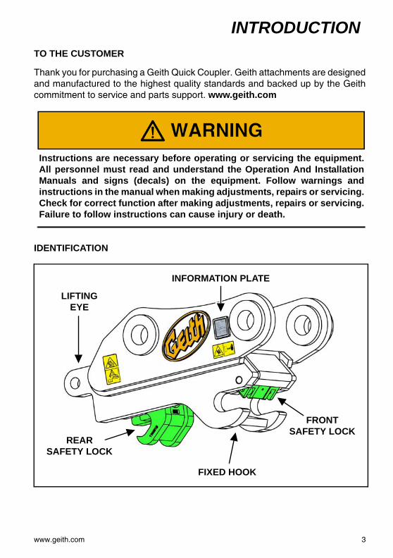
TO THE CUSTOMERThank you for purchasing a Geith Quick Coupler. Geith attachments are designedand manufactured to the highest quality standards and backed up by the Geithcommitment to service and parts support. www.geith.com
Instructions are necessary before operating or servicing the equipment.All personnel must read and understand the Operation And InstallationManuals and signs (decals) on the equipment. Follow warnings andinstructions in the manual when making adjustments, repairs or servicing.Check for correct function after making adjustments, repairs or servicing.Failure to follow instructions can cause injury or death.
IDENTIFICATION
REARSAFETY LOCK
INFORMATION PLATE
LIFTING EYE
FRONT SAFETY LOCK
FIXED HOOK
www.geith.com 3
INTRODUCTION
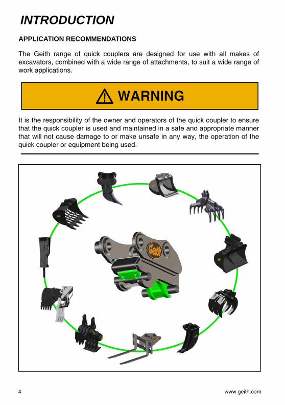
APPLICATION RECOMMENDATIONSThe Geith range of quick couplers are designed for use with all makes ofexcavators, combined with a wide range of attachments, to suit a wide range ofwork applications.
It is the responsibility of the owner and operators of the quick coupler to ensurethat the quick coupler is used and maintained in a safe and appropriate mannerthat will not cause damage to or make unsafe in any way, the operation of thequick coupler or equipment being used.
4 www.geith.com

SAFETY
SAFETY INSTRUCTIONSThis symbol is used to call attention toinstructions concerning personalsafety. Be sure to observe and followthese instructions.
The signal word DANGER on theequipment and in the manualidentifies a hazardous situation which,if not avoided, WILL result in death orserious injury.
The signal word WARNING on themachine and in the manual indicates apotentially hazardous situation which,if not avoided, COULD result in deathor serious injury.
The signal word CAUTION on themachine and in the manual indicates apotentially hazardous situation which,if not avoided, MAY result in minor ormoderate injury. It may also be usedto alert against unsafe practices.
This notice identifies procedureswhich must be followed to avoiddamage to the machine.
Instructions are necessary beforeinstalling, operating or servicingthe equipment. All personnel mustread and understand thisInstallation Guide and theOperation Manual and signs(decals) on the equipment. Followwarnings and instructions in themanual when installing, makingadjustments, repairs or servicing.Check for correct function afterinstalling, making adjustments,repairs or servicing. Failure tofollow instructions can cause injuryor death.
www.geith.com 5

SAFETY
Installation Safety• Position the machine on even, firmand level ground.
• Lower work equipment to theground and stop engine beforeperforming maintenance. Removemachine key.
• Make sure to lock out hydrauliccontrols and place a “DO NOTOPERATE” Warning Tag on themachine to indicate that machineis being serviced and to preventany unauthorized operation.
• Put blocks under track / wheels toprevent the machine from moving.
• Allow the machine to fully coolbefore servicing.
• Always depressurise hydraulicsystem before servicing.
• Collect and retain all oil releasedfrom system during maintenance.
• Welding or grinding painted partsshould be done in well ventilatedareas.
• Wear a dust mask when grindingpainted parts. Toxic dust and gascan be produced.
• Avoid contact with leakinghydraulic fluid or diesel fuel underpressure. It can penetrate skin oreyes.
• Keep arcs, sparks, flames andlighted tobacco away frombatteries.
• When performing maintenance onmachine, prevent tripping andfalling by keeping area aroundyour feet clean and free of objectsand debris.
6 www.geith.com

SAFETY
Welding and GrindingAlways clean machine andattachment, set battery disconnectswitch to “OFF” position, anddisconnect wiring from electroniccontrollers before welding. Coverrubber hoses, battery and all otherflammable parts. Keep a fireextinguisher near machine whenwelding.
Toxic dust or gas can be producedwhen grinding or welding paintedparts. Grinding or welding paintedparts should be done in a wellventilated area. Wear dust mask whengrinding painted parts.
Dust generated from repairingnonmetallic parts such as hoods,fenders or covers can be flammable orexplosive. Repair such components ina well ventilated area away fromflames or sparks.
Do not weld on lines or on tanks thatcontain flammable fluids. Do not flamecut lines or tanks that containflammable fluid. Clean any such linesor tanks thoroughly with anonflammable solvent before weldingor flame cutting.
www.geith.com 7

SAFETY
DECAL INSTALLATIONInstruction and warning decals aresupplied with this quick coupler.
Figure 1
Install the two decals inside of the cabwindow [Figure 1], close to thecontrol box.
NOTE: Replace any damagedinstruction and warningdecals.
Operating Instructions decal (1)[Figure 1].
Operating Instructions decal (2)[Figure 1].
1
2
827000028754B
827000087399
8 www.geith.com

INSTALLATION
KIT COMPONENT IDENTIFICATIONNOTE: Generic list: Content may vary per machine model.
Open kit box and remove all components.
ITEM DESCRIPTION GEITH P/N QTY
1 BOOM HOSE, 2SNK-04S C/W ST/BANJO 3/8 11A BOOM HOSE, 2SNK-04S C/W ST/BANJO 3/8 12 LINK HOSE, 2SNK-04S C/W ST/BANJO 1/4 W/G 1
2A LINK HOSE, 2SNK-04S C/W ST/BANJO 1/4 W/G 13 PUMP HOSE, 2SNK-04S C/W ST/BANJO 3/8 1
3A TANK HOSE, 2SNK-04S C/W ST/BANJO 3/8 1- CABLE TIES 40- 1/4 FEM 90 COMPACT HITCH HOSE ADAPTER 25 SOLENOID VALVE ASSEMBLY 1
5A SUBPLATE, SIDE ENTRY 16 CONTROL BOX 17 3/8 x 3/8 BSP MM 4
7A 1/4 MALE / MALE 705000111307A 38 3/8 BONDED WASHERS 8
8A 1/4 DOWTY 8050000135017 89 1/4 FEM FIXED BARREL 705000111308A 1
10 1/4 BANJO BOLTS / HITCH BOLTS 705000111315A 211 RESTRICTOR 705000111309A 112 1/4 CHECK VALVE 70500000VU14M 113 2 CORE CABLE 703000111465A 114 PRESSURE TEE 115 TANK TEE 116 BUCKET TEE 117 TWIN CLAMP, GROUP 2 (13.5) 705000111318A 3
17A SINGLE CLAMP, GROUP 2 (13.5) 705000111317A 421 CABLE TIES, 7 MM 5022 BOLT, M5 x 40 C/W NUT & WASHER 705000111319A 226 HYDRAULIC SEAL KIT 127 PRESSURE SWITCH, 180 bar 701000135015A 128 HYDRAULIC CYLINDER 129 BRACKET 705000105213B 130 BOLT, M12 x 40 C/W NUT & WASHER31 WIRE HARNESS 705000028744B 132 POPPET VALVE (12V) 705000028745A 1
POPPET VALVE, (24V) 705000028746A 133 SOLENOID VALVE ASSEMBLY (12V) 705000028758A 1
SOLENOID VALVE ASSEMBLY (24V) 705000028759A 134 3/8 x 3/8 BSP M/F 135 WIRE HARNESS 701000028852A 1
www.geith.com 9

INSTALLATION
Coupler Circuit With Four Port Valve And Pressure Switch21
6
10
8
2
7
26, 28
8 10
2A
7
1A 17A
17
135
33
OR 14
14A
2414A
128
11
3
8
10
30
29
103A
OPERATING PUMP TEST PORT
8
8
8
10
27
9 8
16A16B
1634
34
90° ADAPTER
TO BUCKET CYLINDER15
TANK RESERVIOR
FUSE APPLIANCE(CIGARETTE LIGHTER)
AUX. OUTPUT 12/24 V
27 W
10 www.geith.com

INSTALLATION
Coupler Circuit Diagram For Integration Into Plumbed MachineB
V1V2
A
PT
deutsch
deutsch1
2
deutsch
deutsch
deutschdeutsch
deutschdeutsch
16
16A 16B
89
27
34
34
TO BUCKET CYLINDER
32
7
8
34
PREINSTALLED
FOUR PORT VALVE
2A 2
8 8
10
17
10
*NOTE*
*NOTE* Unplug OEM DEUTSCH plug and insert Geith DEUTSCH socket. Insert Geith DEUTSCH plug in OEM DEUTSCH socket.
Pre-installed quick hitch circuit.
Geith Supplied quick hitch circuit.
www.geith.com 11
INSTALLATION
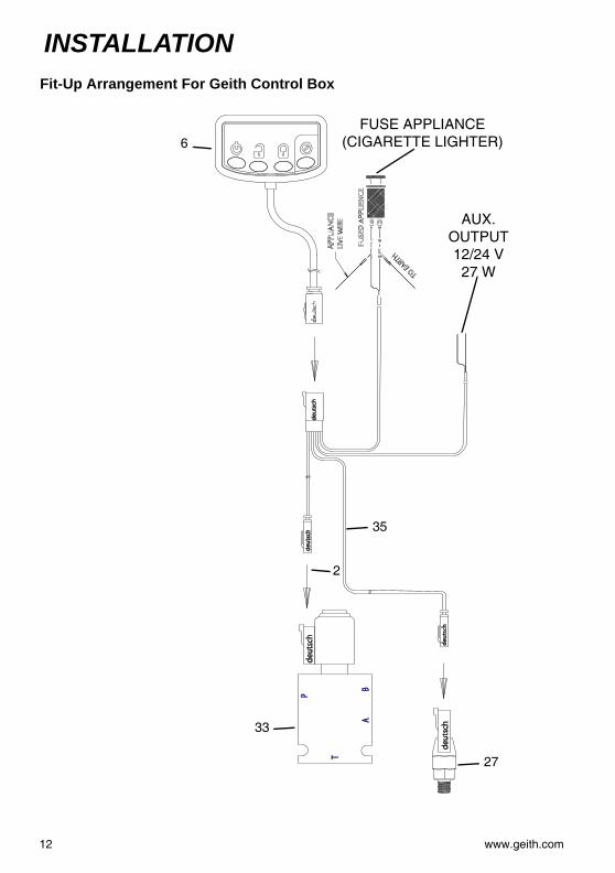
Fit-Up Arrangement For Geith Control Boxdeut
sch
BA
P
T
deut
sch
deut
sch
deut
sch
FUSE
D A
PPLI
ENC
E
TO EARTH
APP
LIA
NCE
LIVE
WIR
E
deut
sch
deut
sch
2
27
35
33
6FUSE APPLIANCE
(CIGARETTE LIGHTER)
AUX. OUTPUT 12/24 V 27 W
12 www.geith.com
INSTALLATION
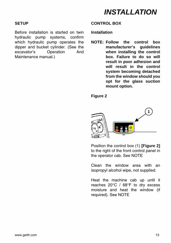
SETUPBefore installation is started on twinhydraulic pump systems, confirmwhich hydraulic pump operates thedipper and bucket cylinder. (See theexcavator’s Operation AndMaintenance manual.)
CONTROL BOX
Installation
NOTE: Follow the control boxmanufacturer’s guidelineswhen installing the controlbox. Failure to do so willresult in poor adhesion andwill result in the controlsystem becoming detachedfrom the window should youopt for the glass suctionmount option.
Figure 2
Position the control box (1) [Figure 2]to the right of the front control panel inthe operator cab. See NOTE
Clean the window area with anisopropyl alcohol wipe, not supplied.
Heat the machine cab up until itreaches 20°C / 68°F to dry excessmoisture and heat the window (ifrequired). See NOTE
1
www.geith.com 13
INSTALLATION
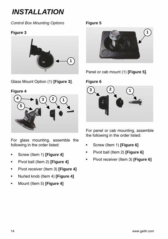
Control Box Mounting OptionsFigure 3
Glass Mount Option (1) [Figure 3].
Figure 4
For glass mounting, assemble thefollowing in the order listed:
• Screw (Item 1) [Figure 4]
• Pivot ball (Item 2) [Figure 4]
• Pivot receiver (Item 3) [Figure 4]
• Nurled knob (Item 4) [Figure 4]
• Mount (Item 5) [Figure 4]
Figure 5
Panel or cab mount (1) [Figure 5].
Figure 6
For panel or cab mounting, assemblethe following in the order listed:
• Screw (Item 1) [Figure 6]
• Pivot ball (Item 2) [Figure 6]
• Pivot receiver (Item 3) [Figure 6]
1
5
4 3 2 1
1
3 2 1
14 www.geith.com

INSTALLATION
Harness ConnectionsFigure 7
Locate a suitable 12 / 24V fusedappliance (cigarette lighter) (1)[Figure 7].
Connect the control box into thedesired fused appliance.
Secure all wiring with tie straps.
Battery Isolator Switch Optional Connection
Figure 8
Connect wire (RED) (1) to fusedappliance, main battery isolator switchor ignition live side. Connect wire(BLACK) (2) [Figure 8] to a groundterminal.
12 / 24V Fused Appliance1
1
2 1
2
www.geith.com 15

INSTALLATION
QUICK COUPLER HYDRAULIC HOSE / ELECTRICAL HARNESS INSTALLATIONBoom (Without Manifold)
The following is a generic boom hoseinstallation. The images may not showyour machine exactly as it appears butthe procedure is correct for allmachines.
AVOID INJURY OR DEATH
Before installing boom hoses:
• Lower the work equipment to theground.
• Stop the engine and remove thekey.
HIGH PRESSURE FLUID HAZARD
To prevent serious injury or deathfrom high pressure fluid:
• Relieve pressure on systembefore repairing or adjusting.
• Wear proper hand and eyeprotection when searching forleaks. Use wood or cardboardinstead of hands.
• Keep all components in goodrepair.
• Stop the engine and release allhydraulic pressure in the system.
16 www.geith.com

INSTALLATION
Figure 9Locate the two link hoses Items 2 &2A on component identification list.
Install and tighten the two link hoses(1) [Figure 9] to the quick couplerhydraulic cylinder (one on either sideof the port block).
Install the quick coupler onto themachine.
NOTE: Verify that all O-ring sealsrequired are fitted to thequick hitch on both link anddipper positions.
Route the link hoses from the quickcoupler cylinder along the arm andboom hoses.
Figure 10
Place a straight edge square on theside of the dipper, place a mark at thetop of the straight edge (1). Place asecond mark (2) [Figure 10]. in thecenter (left to right) of the dipper.
Move up the arm and place thestraight edge square on the side of thedipper. Place a mark at the top of thestraight edge (on the left side ofdipper).
1
1
2
www.geith.com 17

INSTALLATION
Figure 11Locate the two twin clamps Item 17on component identification list.
Using one of the twin clamps, markthe shape (1) [Figure 11] of the baseof the clamp at each of the previouslymarked positions on the dipper.
NOTE: Ensure top clamp is locatedto one side and angledslightly to direct hosesalong the side of the boom.
Eye and body protection is requiredwhen grinding or welding. Wearapproved goggles, helmet andclothing. Failure to wear eye and bodyprotection can result in serious injury.
Using a sharp edged tool, scrape offpaint at edges (2) [Figure 11] ofmarked areas to allow good contact tometal for welding of the hose clampbases.
Before welding, disconnect batterycables. Connect the welding groundas close as possible to the area beingwelded.
Figure 12
Position the clamp base plates (1) inthe marked positions. Weld along topand bottom (2) [Figure 12] edges ofthe clamp base plates to secure inposition.
Repeat this procedure on all clamps.
Clean all welded surfaces.
1
2
1
2
18 www.geith.com
INSTALLATION
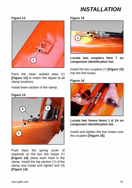
Figure 13Paint the clean welded area (1)[Figure 13] to match the dipper at allclamp locations.
Install lower section of the clamp.
Figure 14
Push back the spring cover (ifrequired) on the two link hoses (1)[Figure 14], place each hose in theclamp. Install the top section (1) of theclamp and install and tighten bolt (3)[Figure 14].
Figure 15
Locate two couplers Item 7 oncomponent identification list.
Install the two couplers (1) [Figure 15]into the link hoses.
Figure 16
Locate two hoses Items 1 & 1A oncomponent identification list.
Install and tighten the two hoses ontothe couplers [Figure 16].
1
1
2 3
1
www.geith.com 19

INSTALLATION
Figure 17Route the two hoses (1) [Figure 17]up the dipper and installing the hosesinto the clamps as needed.
Figure 18
With hoses secured to dipper arm,route the hoses along the existingdipper ram supply hose line [Figure18].
Secure hoses with cable ties along thefull length of the boom [Figure 18].
NOTE: Leave approximately 300mm (12 in.) between cableties.
Figure 19
Route hoses along existing boomsupply hose line at the base of theboom [Figure 19].
Secure hoses with cable ties along thebase of the boom [Figure 19].
1
20 www.geith.com
INSTALLATION
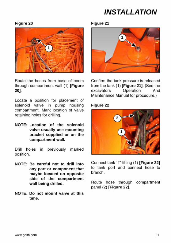
Figure 20Route the hoses from base of boomthrough compartment wall (1) [Figure20].
Locate a position for placement ofsolenoid valve in pump housingcompartment. Mark location of valveretaining holes for drilling.
NOTE: Location of the solenoidvalve usually use mountingbracket supplied or on thecompartment wall.
Drill holes in previously markedposition.
NOTE: Be careful not to drill intoany part or component thatmaybe located on oppositeside of the compartmentwall being drilled.
NOTE: Do not mount valve at thistime.
Figure 21
Confirm the tank pressure is releasedfrom the tank (1) [Figure 21]. (See theexcavators Operation AndMaintenance Manual for procedure.)
Figure 22
Connect tank `T’ fitting (1) [Figure 22]to tank port and connect hose tobranch.
Route hose through compartmentpanel (2) [Figure 22].
1
1
1
2
www.geith.com 21

INSTALLATION
Figure 23Locate and follow the dipper armbucket ram outstroke port supply line(1) [Figure 23] to the base of theboom.
Control Valve And Pressure Switch
Locate the bucket ram `T’ fitting in thekit.
Figure 24
Insert T fitting or flange fitting (1)[Figure 24]. Connect the pressureswitch to the T piece or flange fittingbranch.
Connect the hydraulic hose (RED) tothe hydraulic pump test port.
NOTE: On a twin hydraulic pumpsystem connect thehydraulic hose (RED) to thehydraulic pump test portthat operates the dipper andbucket cylinders.
NOTE: It is recommended to installa T fitting between thehydraulic pump test portand the hydraulic hose forfuture hydraulic pumptesting.
Figure 25
When connecting hydraulic hoses tothe valve body [Figure 26] and quickcoupler [Figure 27], connect thehydraulic hoses in the following order:banjo bolt / hitch bolt (1) through thebonded washer (2), hydraulic hose(3), bonded washer (4) [Figure 25]then into the valve body (not shown).
1
1
1
3
2
4
22 www.geith.com
INSTALLATION
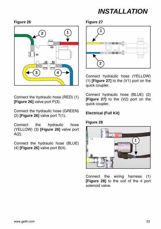
Figure 26Connect the hydraulic hose (RED) (1)[Figure 26] valve port P(3).
Connect the hydraulic hose (GREEN)(2) [Figure 26] valve port T(1).
Connect the hydraulic hose(YELLOW) (3) [Figure 26] valve portA(2).
Connect the hydraulic hose (BLUE)(4) [Figure 26] valve port B(4).
Figure 27
Connect hydraulic hose (YELLOW)(1) [Figure 27] to the (V1) port on thequick coupler.
Connect hydraulic hose (BLUE) (2)[Figure 27] to the (V2) port on thequick coupler.
Electrical (Full Kit)
Figure 28
Connect the wiring harness (1)[Figure 28] to the coil of the 4 portsolenoid valve.
B(4)A(2)
P(3)
T(1)
12
3 4
V1
V2
1
2
1
www.geith.com 23
INSTALLATION
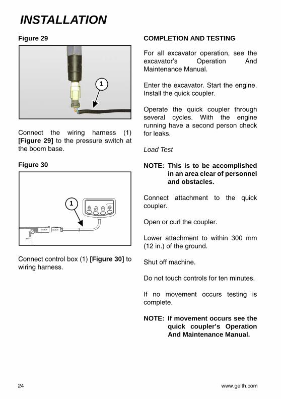
Figure 29Connect the wiring harness (1)[Figure 29] to the pressure switch atthe boom base.
Figure 30
Connect control box (1) [Figure 30] towiring harness.
COMPLETION AND TESTING
For all excavator operation, see theexcavator’s Operation AndMaintenance Manual.
Enter the excavator. Start the engine.Install the quick coupler.
Operate the quick coupler throughseveral cycles. With the enginerunning have a second person checkfor leaks.
Load Test
NOTE: This is to be accomplishedin an area clear of personneland obstacles.
Connect attachment to the quickcoupler.
Open or curl the coupler.
Lower attachment to within 300 mm(12 in.) of the ground.
Shut off machine.
Do not touch controls for ten minutes.
If no movement occurs testing iscomplete.
NOTE: If movement occurs see thequick coupler’s OperationAnd Maintenance Manual.
1
deutsch deutsch
1
24 www.geith.com

WARRANTY
www.geith.com 25

WARRANTY
WARRANTY PROGRAMThe Company warrants the Equipment (except for parts) sold by it to thePurchaser to be:
• Free of defects in material and workmanship for a period of twelve (12)months from the date of shipment or 2000 hours of use, whichever first occursunless formal documentation can be produced when the product has been putinto use. A period of six (6) months shelf life will be accepted on all products.Any product not put into use before the six (6) months stocking and twelve(12) warranty period will forfeit any warranty given on the product. The Geithgeneric installation/hose assemblies will be covered for a period of six (6)months from the date of shipment (installation kit covered only in Europe).
• The applicable warranty time period for parts shall be six (6) months from thedate of shipment and for reconditioned parts or products shall be three (3)months from the date of shipment. At the discretion of the company a longerthirty six (36) month warranty period may be offered to selected customers.This warranty period only covers the frame/chassis of the product andexcludes all other components attached to the frame/chassis.
• No warranty will be accepted for wear/damage on products or componentsthereof.
The Company will provide a new part or repaired part, at its election, in place ofany part which is found upon its inspection to be defective in material orworkmanship during the periods described above. Such part will be repaired orreplaced without charge to the Purchaser providing the warranty cost does notexceed the standard cost which has been set out by the company in the standardcost table (this cost is available upon request). The company will accept maximumwarranty costs not exceeding the original sale value.
The replacement or repair must be carried out during normal working hours at theplace of business of a distributor of the Company authorised to sell the type ofEquipment involved or other establishment authorized by the Company. Thepurchaser must report failures within a maximum time of 30 days of occurrenceand file a warranty claim within a maximum of 30 days thereafter. Warranty claimsoutside this period of time will forfeit the warranty cover.
26 www.geith.com

WARRANTY
Purchaser must present proof of purchase (and purchase date) at the time ofmaking a claim under this warranty. Warranty claims do not apply to failuresoccurring as a result of abuse, misuse, negligent repairs, corrosion, erosion,normal wear and tear, alterations or modifications (which includes use of nonGeith control systems) made to the Equipment without express written consent ofthe Company, or failure to follow the recommended operating practices, or serviceand maintenance procedures as provided in the Equipment's operating andmaintenance publications. All maintenance, service and repair work must becompleted by an authorised Company distributor or establishment and onlygenuine Company parts shall be used in such work. Failure to comply strictly withthese requirements shall invalidate this warranty. The warranty provided hereindoes not apply to any components which are not supplied by the company (thisincludes engines, hydraulic systems, boom, dipper, etc) which are manufacturedby others as they are warranted by their respective manufacturers directly to thePurchaser.THE COMPANY DISCLAIMS AND EXCLUDES ALL OTHER CONDITIONS,WARRANTIES OR REPRESENTATIONS OF ALL KINDS, EXPRESS ORIMPLIED, STATUTORY OR OTHERWISE (EXCEPT THAT OF TITLE),INCLUDING ALL IMPLIED WARRANTIES AND CONDITIONS RELATING TOMERCHANTABILITY, SATISFACTORY QUALITY AND FITNESS FOR APARTICULAR PURPOSE. Corrections by the Company of nonconformitieswhether patent or latent, in the manner and for the period of time provided aboveshall constitute fulfillment of all liabilities of the Company for such nonconformities,whether based on contract, warranty, tort, negligence, indemnity, strict liability orotherwise with respect to or arising out of such Equipment.
LIMITATION OF LIABILITY
THE REMEDIES OF THE PURCHASER SET FORTH HEREIN ARE EXCLUSIVEAND THE TOTAL LIABILITY OF THE COMPANY WITH RESPECT TO THECONTRACT OR THE EQUIPMENT AND SERVICES FURNISHEDHEREUNDER, IN CONNECTION WITH THE PERFORMANCE OR BREACHTHEREOF OR FROM THE MANUFACTURE, SALE, DELIVERY,INSTALLATION, REPAIR OR TECHNICAL DIRECTION COVERED BY ORFURNISHED UNDER THE CONTRACT, WHETHER BASED ON CONTRACT,WARRANTY, TORT, NEGLIGENCE, INDEMNITY, STRICT LIABILITY OROTHERWISE, SHALL NOT EXCEED THE PURCHASE PRICE OF THE UNIT OFEQUIPMENT UPON WHICH SUCH LIABILITY IS BASED. THE COMPANYAND ITS SUPPLIERS SHALL IN NO EVENT BE LIABLE TO THE PURCHASER,ANY SUCCESSORS IN INTEREST OR ANY BENEFICIARY OR ASSIGNEE OFTHE CONTRACT FOR ANY CONSEQUENTIAL INCIDENTAL, INDIRECT,
www.geith.com 27
WARRANTY
SPECIAL OR PUNITIVE DAMAGES ARISING OUT OF THE CONTRACT, ORANY BREACH HEREOF, OR ANY DEFECT IN, OR FAILURE OF, ORMALFUNCTION OF THE EUQIPMENT SUPPLIED HEREUNDER WHETHERBASED UPON LOSS OF USE, LOST PROFITS, REVENUE OR INTEREST,LOST GOODWILL, WORK STOPPAGE, IMPAIRMENT OF OTHER GOODS,LOSS BY REASON OF SHUTDOWN OR NON-OPERATION, INCREASEDEXPENSES OF OPERATION, COST OF PURCHASE OF REPLACEMENTPOWER OR CLAIMS OF THE PURCHASER OR CUSTOMERS OF THEPURCHASER FOR SERVICE INTERRUPTION, WHETHER OR NOT SUCHLOSS OR DAMAGE IS BASED ON CONTRACT, WARRANTY, TORT,NEGLIGENCE, INDEMNITY, STRICT LIABILITY OR OTHERWISE.VIOLATIONS OF LAW
The Company shall not be bound by or required to adhere to any term or provisionof a purchase order, quotation, bid, letter of credit or like document or anyprovision of law, regulation or custom, which would cause the Company, its parentor any of its affiliates to be in violation of or fail to comply with the export laws,taxing statutes or regulations of the country wherein the Equipment ismanufactured or from which it is exported or is otherwise subject to jurisdiction.
GOVERNING LAW
The rights and obligations of the Purchaser and the Company shall be governedand construed in accordance with the laws of the Republic of Ireland and thePurchaser submits to the exclusive jurisdiction of the Irish Courts.
MODIFICATIONS, SEVERABILITY AND ENTIRE AGREEMENT
The Company shall not be bound by any amendment or any modification to theContract until approved in writing by an officer of the Company. The Contractwhen so approved, shall supersede all previous communications, either oral orwritten. If any clause of the Contract is held by any competent authority to beinvalid or unenforceable in whole or in part, the other clauses of the Contract andthe remainder of the clause in question shall not be affected thereby.
TA detailed description of terms and conditions of sale can be found on QR39Geith terms and conditions of sale which was attached to your orderacknowledgement. If you do not have a copy you can contact your nearest GeithDistributor.
28 www.geith.com


www.gei
15 7QU, UK
Contact us:Ireland - Geith InternationalGrangegeeth, Slane, CO. Meath, IrelandT: +353 (0)41 982 4183 F: +353 (0)41 982 [email protected]
UK - Geith International UK LtdUnit 6, Hoel - Y - Gamlas, Parc Nantgarw, Nantgarw, Cardi�, CFT: +44 (0)1443 845 666 F: +44 (0)1443 844 [email protected]
US - Geith Inc2905 Shawnee Industrial Way, Shawnee, GA 30024T: +1 866 472 4373 (Toll Free) F: +1 866 472 [email protected]
th.com
France - Agent Commercial France de Geith International Ltd203 route de Grenoble, 69800 Saint Priest, FranceNo Vert: 0800916626 F: +33 (0)4 72 79 32 [email protected]