general 2/4-electrode design for conductivity … · 2/4-electrode design for conductivity ......
TRANSCRIPT

2/4-electrode design for Conductivity Flow fittings, Subassemblies and Immersion fittingsModel SC42 and FF40/FS40/FD40
GS 12D7J1-01E-H10th Edition
The measurement of specific conductivity in aqueoussolutions is becoming increasingly important for the determinationof impurities in water or the concentration measurement ofdissolved chemicals. The accuracy of the measurement is stronglyinfluenced by temperature variations, polarisation effects at thesurface of the contacting electrodes, cable capacitances, etc.
Yokogawa provides sensors for pure water systems, generalapplications with a 2-electrode design and applications involvinghigh concentrations of chemicals with a 4-electrode design.
To install conductivity sensors in a permanent or semi-permanentlocation, Yokogama offers wide a range of flow and immersionfittings. A high degree of standardisation simplifies mounting,servicing and removal or replacement of the sensors.
Included are flow fittings and subassemblies for in-line or direct mounting of conductivity sensors in pipingsystems.
The immersion fittings are designed for tanks, open vessels ordrains. PVC and stainless steel construction materials suit mostprocess conditions, regarding chemical resistance, pressure andtemperature specifications.
The fiitings of stainless steel might be used in sanitaryapplications.
FEATURES● Wide range of sensors to suit most process conditions.● High precision of the cell constant (Field calibration not
necessary).● Sensors for ultra-pure water applications.● Built-in resistance thermometers Pt 1000 for automatic
temperature compensation.● Optional material certificate 3.1 B according to EN-10-24
(DIN50049) for stainless steel sensors.● Optional quality inspection certificate.
GeneralSpecifications
SYSTEM CONFIGURATION
Sensors Cables Fittings Transmitters AccessoriesSensors Fittings

PLUG-IN FLOW SENSORS (SS)
Stainless steel cells for 2-electrode type with cellconstants 0.01 and 0.1 cm-1.These conductivity sensors have a stainless steel body and PEEK(polyether-ether-ketone) inner insulation for highpressure/temperature applications. A special treatment of theelectrodes ensures optimal resistance against polarisation. Thesensor includes a built-in resistance thermometer Pt1000 forautomatic temperature compensation.The combination sensor plug and cable socket is watertight andtemperature resistant up to 100 ºC (212 ºF). It meets therequirements of IP 65.The dimensions of the sensor are standardised for mounting inthe standard fitting program of Yokogawa.
FEATURES● High precision of the cell constant (individually calibrated).● Fast temperature response.● High pressure/temperature specifications.● Built-in resistance thermometer, Pt1000 RTD● Plug-socket cable connection for easy installation and
maintenance, meeting IP 65.● Standardised dimensions for mounting in flow- and immersion
fittings.
TYPICAL APPLICATIONS1. Cell constant = 0.01 cm-1
For measurement in very low conductive solutions like purewater, condensate, demineralised water, distilled water, etc.
2. Cell constant = 0.1 cm-1
For measurement of low conductive solutions like boiler feedwater, surface water, etc.
GENERAL SPECIFICATIONSMaterialsWetted parts
a. Body : Stainless steel AISI 316b. Insulation : PEEK (polyether-ether-ketone)c. Electrode : Stainless steel AISI 316d. quad-rings, O-rings : Viton
Connector : Polyamide with gold platedcontacts
Weight and immersion length (L in figure)Model SC42-SP24 : 440 gram; 110 mm (L)Model SC42-SP34 : 600 gram; 163 mm (L)
FUNCTIONAL SPECIFICATIONS
2
GS 12D7J1-01E-H
ø 36
2010
L
ø 30
1256
SC42-SP34SC42-SP24
Unit: mm (inch)
OUT
Model Temp. element Cell-constant Pressure rating Max. temperature 90% Temp. response Measurement systemSC42-SP34 Platinum resistor 0.01 cm-1 10 bar/142 PSIG 150 ºC/302 ºF < 1 min. 2-electrode system
(Pt1000 to DIN)SC42-SP24 Platinum resistor 0.1 cm-1 10 bar/142 PSIG 150 ºC/302 ºF < 3 min. 2-electrode system
(Pt1000 to DIN)
Flow type
The maximum pressure and temperature rating also depend on the actual process conditions. Under certain circumstances it is necessary totest the cell in situ. Additional data is available from Yokogawa.
NOTE: Stainless steel cells for 2-electrode systems with cell-constants 0.01 and 0.1 cm-1 designed for pressure and temperature ratings ofup to 40 bar (PSIG) at 250 ºC (ºF) are available upon request.
OPTIONSCertificate /M : Material certificate 3.1B
According to EN-10-24(DIN50-049) (on wetted parts)
/Q : Quality inspection certificate
IN

3
GS 12D7J1-01E-H
PLUG-IN FLOW SENSORS (EPOXY)
Epoxy cells for 2- and 4-electrode type with cell-constants1 and 10 cm-1.These conductivity sensors have a body of glass-filled epoxyresin. The electrodes are made from graphite impregnated withepoxy resin. This gives the sensors a good chemical resistanceand a good reduction of polarisation effects.
FEATURES● Good chemical resistance.● Choice in 2- and 4-electrode types.
GENERAL SPECIFICATIONSMaterialsWetted parts
a. Body : Glass filled epoxy resinb. Electrodes : Graphite impregnated with
epoxy resinConnector plug : Polyamide with gold plated
contacts
Weight and immersion length (L in figure)Model SC42-EP0. : 270 gram; 193 mm (L)Model SC42-EP1. : 220 gram; 160 mm (L)
OPTIONSCertificate /Q : Quality inspection certificate
FUNCTIONAL SPECIFICATIONS
ø 30(1.18")
ø 36(1.42") 10
(0.4
0")
L20
(0.7
8")
30(1
.18"
)43
(1.6
9")
ø d
SC42-EP04SC42-EP14SC42-EP08SC42-EP18
Unit: mm (inch)
Out
Model Temp. element Cell constant Pressure rating Max. temperature 90% Temp. response Inlet dø Meas. systemSC42-EP04 Pt1000 10 cm-1 10 bar/142 PSIG 110 ºC/230 ºF < 3 min. 5 mm 2-el.ectrodeSC42-EP14 Pt1000 1 cm-1 10 bar/142 PSIG 110 ºC/230 ºF < 2 min. 10 mm 2-el.ectrodeSC42-EP08 Pt1000 10 cm-1 10 bar/142 PSIG 110 ºC/230 ºF < 3 min. 5 mm 4-el.ectrodeSC42-EP18 Pt1000 1 cm-1 10 bar/142 PSIG 110 ºC/230 ºF < 2 min. 10 mm 4-el.ectrode
Flow type
1
2
35
6
4CELLPt 1000
Connector 4-electrode system
The maximum pressure and temperature rating also depend on the actual process conditions. Under certain circumstances it is necessary totest the cell in situ. Additional data is available from Yokogawa.
1
23
5
6
4Pt 1000
CELL
Connector 2-electrode system

ø 29(1.14")
26(1
.02"
)
ø 36(1.42")
10(0
.40"
) L
20(0
.78"
)
46(1
.81"
)30
(1.1
8")
ø 5(0.20")
Weight and immersion length Model SC42-FP0 : ca. 270 gram; 193 mmModel SC42-TP0 : ca. 320 gram; 193 mm
WARNING:Temperature shocks should be avoided
OPTIONSCertificate /Q : Quality inspection certificate
SC42-FP04SC42-TP04SC42-FP08SC42-TP08
Unit: mm (inch)
Flow type
4
GS 12D7J1-01E-H
PLUG-IN FLOW SENSORS (PTFE AND PVDF)
PTFE or PVDF shielded glass-platinum cells for 2- and 4-electrode type with cell constant 10 cm-1.These conductivity sensors are excellent suited for measurementin aggressive media. The (protection) body consists of PVDF(Kynar) or PTFE (Teflon with 25% glass filling).The cell itself is made from highly resistant glass with platinumelectrodes. The electrodes surfaces of the 2-electrode cells(SC42-P04) are further enhanced by gold plating to minimize thepolarisation effects.The internal sealing between the glass measuring cell and thePTFE/PVDF body (not visible in drawing) is by a KALREZ O-ring(high quality with excellent chemical resistance). A VITON O-ringis supplied with the sensors for sealing the cell in the fitting(visible in drawing). For measurements in strongly oxidizing acidsan optional KALREZ O-ring is recommended.
FEATURES● Excellent chemical resistance for applications in aggressive
media like oleum, concentrated mineral acids, etc.● Suitable for measurement of highly conductive, strongly
poluted solutions.● Optimum results by gold plating (of 2-electrode version)
against polarisation effects.
TYPICAL APPLICATIONSPTFE-cell : Concentrated mineral acids such as: oleum,
nitric acid, hydrochloric acid, etc.PVDF-cell : All aggressive media with the exception of
strongly oxidizing agents.NOTE:See the chemical resistance list in table 1.
GENERAL SPECIFICATIONSMaterialsWetted partsa. Body (shield) : - PVDF (Kynar®) for model SC42-FP04/FP08.
- PTFE (Teflon® with 25% glass) for modelSC42-TP04/TP08
b. O-ring : - KALREZTM for cell-body sealing- VITONTM for sealing in het fitting
c. Electrodes : Platinum, Gold plated for 2-electrode systemd. Inside cell : Glass tube
Connector plug : Polyamide with gold plated contacts
FUNCTIONAL SPECIFICATIONS
Out
Model Temp. element Cell-constant Pressure rating Max. temperature 90% Temp. response Measurement systemSC42-FP04 PT1000 10 cm-1 10 bar/142 PSIG 110 ºC/230 ºF < 1 min. 2-electrode systemSC42-TP04 PT1000 10 cm-1 2 bar/28,5 PSIG 110 ºC/230 ºF < 1 min. 2-electrode systemSC42-FP08 PT1000 10 cm-1 10 bar/142 PSIG 110 ºC/230 ºF < 1 min. 4-electrode systemSC42-TP08 PT1000 10 cm-1 2 bar/28,5 PSIG 110 ºC/230 ºF < 1 min. 4-electrode system
The maximum pressure and temperature rating also depend on the actual process conditions. Under certain circumstances it is necessary totest the cell in situ. Additional data is available from Yokogawa.

5
INSERTION SENSORS
Insertion sensors for 2-electrode type with cell constant 1cm-1.The insertion sensors are especially useful in applications where arepresentative sample flow through the sensor cannot beachieved easily (e.g. in liquids containing solids, directmeasurement in pipe-lines). The electrode surfaces are easilyaccessed for cleaning or maintenance. The model SC4.-EP15D isespecially designed for direct mounting in sanitary pipingsystems. It has a collar piece suitable for mounting with DN 25.
FEATURES● No obstacles in the flow-line by short immersion length.● Easy cleaning.● Good chemical resistance.● Low polarisation distortion.
In addition to that the model SC42-EP15D can be directly fittedwith a DN25 swivel.
APPLICATIONSFor measurement of moderate conductive solutions like surfacewater, waste water, salt solutions, etc.
GENERAL SPECIFICATIONSMaterialsWetted parts
a. Body : Glass-filled epoxy resinb. Electrodes : Graphite impregnated with epoxy
Connector plug : Polyamide with gold plated contactsWeight and immersion length (L in figure)Model SC42-EP15 : 150 gram; 100 mmModel SC42-EP15D : 150 gram; 65 mm
OPTIONSCertificate /Q : Quality inspection certificate
PARTS AND ACCESSORIES
To connect the conductivity sensors to a transmitter or converterYokogawa supplies special cables already pretreated and equippedwith numbers for easy connection to Yokogawa instruments.
K1500FX Set of 5 0-rings for sealing the cell inthe fitting material: silicone rubber.
K1500AG Set of 5 0-rings for sealing the cell inthe fitting material: VITONTM.
K1500AH One (1) KALREZTM 0-ring for sealing thecell in the fitting.
SELECTION CRITERIA
A good indication of construction materials can be taken from thepiping material used in the process equipment. If this material ofbetter is used no problems by corrosion will occur.
In considering the required sensor, please check all four pointslisted hereafter:- The pressure and temperature requirements are within the
limits of the cell.- The selected materials (wetted parts) have a good resistance
to corrosion according to practice or table 2.- The conductivity value at the process temperature is within
the application range of the cell (see figure 1).- A selection is made between 2- or 4-electrode measuring
system (see figure 1).
Model Description LengthWU40-LH01 Conductivity cable 1.0 mWU40-LH02 Conductivity cable 2.0 mWU40-LH05 Conductivity cable 5.5 mWU40-LH10 Conductivity cable 10 mWU40-LH15 Conductivity cable 15mWU40-LH20 Conductivity cable 20 mWU40-LH25 Conductivity cable 25 m
SC42-SP34(0.01/cm)
SC4A-002(0.02/cm)
SC42-SP24(0.1/cm)
SC4A-010(0.1/cm)
SC42-EP14(1/cm)
SC42-EP15(D)(1/cm)
SC42-EP04SC42-FP04SC42-TP04
(10/cm)
SC402/SC202/SC150DC402
SC42-EP18(1/cm)
SC42-EP08SC42-FP08SC42-TP04
(10/cm)
100 000 000.00
10 000 000.00
1 000 000.00
100 000.00
10 000.00
1 000.00
100.00
10.00
1.00
0.10
0.01
µS/cm
SC150
SC202
SC402
WU40-LH2
Model Temp. element Cell-constant Pressure rating Max. temperature 90% Temp. response Measurement systemSC42-EP15 Pt1000 1 cm-1 10 bar/142 PSIG 110 ºC/230 ºF < 3 min. 2-electrode systemSC42-EP15D Pt1000 1 cm-1 10 bar/142 PSIG 110 ºC/230 ºF < 3 min. 2-electrode system
FUNCTIONAL SPECIFICATIONS Figure 1
ø 25
15
L
ø 44
2010
ø 25
15
ø 36
2010
L
SC42-EP15
Insertion type
SC42-EP15D
Insertion type (sanitary)
Unit: mm (inch) Unit: mm (inch)
The maximum pressure and temperature rating also depend on the actual process conditions. Under certain circumstances it is necessary totest the cell in situ. Additional data is available from Yokogawa. GS 12D7J1-01E-H
0 10 20 30 40 50 60 70 80 100 120 140 160
bar
2
4
6
8
10
12AISI 316
PVDFPPPVC
6
GS 12D7J1-01E-H
Ø 35(1.38)
Ø 70 (2.76)
32(1.26)
IN
Ø 40 (1.57)
120
(4.7
2)(a
dj.)
153
(6.0
)231
(9.0
9)
FLOWDirection
IN
OUT
245
(9.6
5)
Ø 60(Ø 2.36)
125
(4.9
2)
87 (
3.42
)
Ø 12
OUT
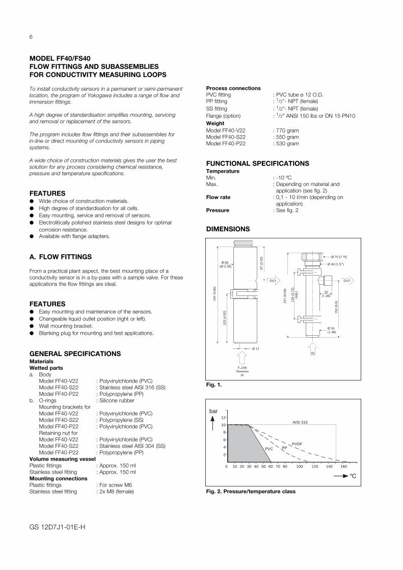
MODEL FF40/FS40FLOW FITTINGS AND SUBASSEMBLIESFOR CONDUCTIVITY MEASURING LOOPS
To install conductivity sensors in a permanent or semi-permanentlocation, the program of Yokogawa includes a range of flow andimmersion fittings.
A high degree of standardisation simplifies mounting, servicingand removal or replacement of the sensors.
The program includes flow fittings and their subassemblies for in-line or direct mounting of conductivity sensors in pipingsystems.
A wide choice of construction materials gives the user the bestsolution for any process considering chemical resistance,pressure and temperature specifications.
FEATURES● Wide choice of construction materials.● High degree of standardisation for all cells.● Easy mounting, service and removal of sensors.● Electrolitically polished stainless steel designs for optimal
corrosion resistance.● Available with flange adapters.
A. FLOW FITTINGS
From a practical plant aspect, the best mounting place of aconductivity sensor is in a by-pass with a sample valve. For theseapplications the flow fittings are ideal.
FEATURES● Easy mounting and maintenance of the sensors.● Changeable liquid outlet position (right or left).● Wall mounting bracket.● Blanking plug for mounting and test applications.
GENERAL SPECIFICATIONSMaterialsWetted partsa. Body
Model FF40-V22 : Polyvinylchloride (PVC)Model FF40-S22 : Stainless steel AISI 316 (SS)Model FF40-P22 : Polypropylene (PP)
b. O-rings : Silicone rubberMounting brackets for Model FF40-V22 : Polyvinylchloride (PVC)Model FF40-S22 : Polypropylene (SS)Model FF40-P22 : Polyvinylchloride (PVC)Retaining nut forModel FF40-V22 : Polyvinylchloride (PVC)Model FF40-S22 : Stainless steel AISI 304 (SS)Model FF40-P22 : Polypropylene (PP)
Volume measuring vesselPlastic fittings : Approx. 150 mlStainless steel fitting : Approx. 150 mlMounting connectionsPlastic fittings : For screw M6Stainless steel fitting : 2x M8 (female)
DIMENSIONS
Fig. 2. Pressure/temperature class
Fig. 1.
Process connectionsPVC fitting : PVC tube ø 12 O.D.PP fitting : 1/2”- NPT (female)SS fitting : 1/2”- NPT (female)Flange (option) : 1/2” ANSI 150 lbs or DN 15 PN10WeightModel FF40-V22 : 770 gramModel FF40-S22 : 550 gramModel FF40-P22 : 530 gram
FUNCTIONAL SPECIFICATIONSTemperatureMin. : -10 ºCMax. : Depending on material and
application (see fig. 2)Flow rate : 0,1 - 10 l/min (depending on
application)Pressure : See fig. 2

7
L1
Ø 36
Ø 70
32
231
IN
OUT
L2
Type NW15ND10 NW25-ND10 1/2” 150 lbs 1” 150 lbsL1 L2 L1 L2 L1 L2 L1 L2
FF40-S22 226 123 236 133 8 7/8” 4 13/16” 9 5/16” 5 1/4”FF40-P22 247 123 236 112 9 3/4” 4 7/8” 9 5/16” 4 7/16”
Sensor cable
Plug-insensor
Stainless steel flow fittingPVC/PP flow fitting
Sensor cable
Plug-insensor
M8 thread
MODEL AND SUFFIX CODES
GS 12D7J1-01E-H
Model Suffix Option Descriptioncode code
FF40 .................................... Flow fittingMaterial -P22 ............................ Polypropylene
-S22 ............................ Stainless steel -V22 ............................ Polyvinylchloride
Options /FP1..... DN15 PN10 PPFlange adapters /FP2 ..... DN25 PN10 PP(NPT 1/2” Male lap joint) /FP3 ..... 1/2” ANSI 150lbs PP
/FP4 ..... 1” ANSI 150lbs PP/FS1..... DN15 PN10 SS AISI 316/FS2..... DN25 PN10 SS AISI 316/FS3..... 1/2” ANSI 150lbs AISI 316/FS4..... 1” ANSI 150lbs AISI 316
Certificate /M..... Material certificate 3.1BAccording to EN-10-024(DIN50-049) (For SS wetted parts only)

8
GS 12D7J1-01E-H
B. SUBASSEMBLIES
The subassemblies are designed for mounting conductivitysensors in a tank wall or directly into a piping system.They can be easily mounted in the process piping by welding,cementing or screwing.
The stainless steel subassemblies meet the requirements of DIN 11850 and DIN 11851 for sanitary constructions.
FEATURES• Suitable for mounting in a T-piece or directly in the piping
system.• Designs for mounting the plug-in type sensor and the
insertion type sensor with collar piece DN 25 (D-model).
GENERAL SPECIFICATIONSMaterialsWetted partsa. Body
Model FS40-S22-WE : Stainless steel AISI 316 (SS)Model FS40-S22-TP : Stainless steel AISI 316 (SS)Model FS40-S23-DF : Stainless steel AISI 316(SS)Model FS40-F22-PA : Polyvinyldenefluoride (PVDF)Model FS40-F22-TP : Polyvinyldenefluoride (PVDF)Model FS40-V22-WE : Polyvinylchloride (PVC)Model FS40-V22-TP : Polyvinylchloride (PVC)
b. Sealing ringSilicone rubber : DIN/ISO 1629 code VMQBuna N : DIN/ISO 1629 code NBRPerfluorelastomer : DIN/ISO 1629 code PFPM
Process connectionsModel FS40-S22-WE : DN32Model FS40-S22-TP : 11/4”- 11,5 NPTModel FS40-S23-DF : DN25Model FS40-F22-PA : ISO 228/1 - G 11/4” (BSPP)Model FS40-F22-TP : 11/4”- 11,5 NPTModel FS40-V22-WE : DN32Model FS40-V22-TP : 11/4”- 11,5 NPT
WeightModel FS40-S22-WE : 0.21 kgModel FS40-S22-TP : 0.30 kgModel FS40-S23-DF : 0.13 kgModel FS40-F22-PA : 0.10 kgModel FS40-V22-WE : 0.45 kgModel FS40-V22-TP : 0.12 kgModel FS40-F22-PA : 0.13 kg
FUNCTIONAL SPECIFICATIONSTemperatureMin. : -10 ºC (14 ºF)Max. : Depending on material (see fig. 2)Pressure : See fig. 2
Sensor(D-model)
Partnumber(82895488)
FS40-S23DF
Fig. 3. Installation example
MODEL AND SUFFIX CODES
Model Sufix Option Descriptioncode code
FS40 Flow fitting subassemblyMaterial -F22 Polyvinyldenefluoride (PVDF)
-S22 Stainless steel (SS)-V22 Polyvinylchloride (PVC)-S23 Stainless steel D-Model (SS)
Mounting -WE Weld-in socket for S versionGlue-in socket for V version.
-PA Parallel thread, only for PVDF version (ISO 2281- G11/4”)
-TP Tapered pipe thread (11/4” NPT)
-DF For insertion type sensorwith collar piece DN25only (only for S23)
Certificate /M Material certificate 3.1Baccording to EN-10 024(DIN 50049) (on wetted parts)
FS40-S23-DF

9
SERVICE PARTS
DIMENSIONS
Unit: mm (inch)
24 (
0.95
)Ø 63(2.48)
FS40-S23-DF
Ø 28(1.10)
Ø 31(1.22)
FS40-V22-TPFS40-F22-TP
61 (
2.40
) Ø 55(2.16)
1 1/4"-11.5NPT
36 (
1.42
)27
(1.
06)
FS40-S22-WE
Ø 54(2.12)
Ø 38(1.50)
36 (
1.42
)
Ø 36(1.42)
27 (
1.06
)
50 (
1.97
)
FS40-S22-TP
Ø 54(2.12)
1 1/4" NPT41 (
1.61
)
52 (
2.05
)
Ø 55(2.16)
1 1/4" ISO228/1-G 1 1/4
27 (
1.06
)19
(0.
75)
FS40-F22-PA
57 (
2.25
) Ø 50(1.97)
32 (
1.26
)24
(0.
95)
Ø 40(1.57)
FS40-V22-WE
ACCESSORIES AND OPTIONS
Type DescriptionBA10 Connection box (between fitting and
transmitter)BP10 Ditto (IS design)WF10 Connecting cable (between connecting box
and transmitter)WU40-LH01 Sensor cable (1 m)WU40-LH02 Sensor cable (2 m)WU40-LH05 Sensor cable (5,5 m)WU40-LH10 Sensor cable (10 m)WU40-LH15 Sensor cable (15 m)WU40-LH20 Sensor cable (20 m)WU40-LH25 Sensor cable (25 m)
Type DescriptionK1500AR Silicone O-rings (42.52 x 2.62) for PVDF
subassembly (qty. 5)K1500HE Sealing rings (29.74 x 3.53) for SS
subassembly (D-model)K1500FX Silicone O-rings (29.74 x 3.53) for other fittings
and subassemblies (qty. 5)K1500AH Perfluorelastomer O-ring (Kalrez) (29.74 x 3.53)
for fittings and subassemblies (optional), exceptfor the DF style (qty. 1)
K1500AK EPDM O-rings (29.74 x 3.53) for fittings andsubassemblies (optional), except for the DFmodel (qty. 5)
ORDERING INSTRUCTIONSWhen ordering, specify model and code, item name and partnumbers:
1. Flow fitting : FF40-P22, FF40-S22 or FF40-V222. Subassembly : FS40-F22-.., FS40-S22-.., FS40-V22-..
(flow fitting) or FS40-S23-DF3. Sensor cable, : WU40-LH01, WU40-LH02, WU40-
LH05, WU40-LH10if relevant WU40-LH15, WU40-LH20 and
WU40-LH25.4. Connecting box/connecting cable (only when converter is
installed a distance from the fitting): BA10/WF10 or BP10/WF10 (IS Design)
5. Accesories : Part name and part number (quantity)6. Service parts : Part name and part number (quantity)
Bad Bad
Reasonable Good
Good
GS 12D7J1-01E-H
Fig. 5. Mounting position sensors
Fig. 4. Flow Fittings subassembly

10
GS 12D7J1-01E-H
Ø 50
Ø 38
Min. 490Max. 1990
Sensor lengthminus 5 mm
d
kD
SS
mm (inches)
Ø 40 (1.57)
Ø 50 (1.97)
90 (
3.54
)
L
18 (0.70)
78 (3.07)125 (4.92)168 (6.60)
Ø 100 (3.94)
18 (0.70)
PVC
mm (inches)
MODEL FD40 IMMERSION FITTINGSFOR CONDUCTIVITY MEASURING LOOPSFor installing conductivity sensors in a permanent or semi-permanent location, the program of Yokogawa includes a rangeof flow and immersion fittings.
The immersion fittings are for installing conductivity sensors intanks, open vessels or drains. The constructions of PVC andstainless steel suit most process conditions, considering chemicalresistance, pressure and temperature specifications. The fittingsof stainless steel might be used in sanitary applications. Amounting flange can be ordered.
FEATURES● Designed for mounting conductivity sensors in tanks, open
vessels and drains.● Easy mounting, service and removal or replacement of
sensors.● High pressure and temperature specifications.● With or without flanged connection.● Stainless steel construction for sanitary applications.● Several lengths available.
From a practical plant aspect, the immersion fittings should beinstalled in a site, where the point of measurement truly representsthe entire solution. Avoid areas where the measurement variessignificantly. If the fitting is mounted in a tank with agitator, or if it
is placed in a fast flowing process, care must be taken that thefitting is adequately supported. Select a mounting place where thesensor is always immersed in the process liquid.GENERAL SPECIFICATIONSWetted parts Materialsa. Body : Stainless steel AISI 316 (SS)
Polyvinylchloride (PVC) (refer to model code)
b. O-rings : Silicone rubber (other materials see accessories)
Sensor cable : Six wire multicore, covered withthermoplastic PVC length: 5.5 m or 10 m
Blanking plug* : Ryton R4Weight (without flange) : a. PVC fitting 1.7 kg
b. SS fitting 4.5 kg
* This plug is for test applications only and must be removedbefore mounting the sensor.
FUNCTIONAL SPECIFICATIONSTemperatureMin. : -10 ºC (14 ºF)Max. : Depending on material and
application (see fig. 3)Pressure : See fig. 3Immersion length fitting : 0.5 to 2.0 m (in steps of dm)
Flange D k dNW50 165 125 182”150 lbs 152.4 120.7 19.1
(6”) (4.75”) (0.75”)

Type Description
BA10 Connection box (between fitting andtransmitter)
WF10 Connecting cable (between connecting boxand transmitter)
WU40-LH05 Sensor cable (5,5 m)WU40-LH10 Sensor cable (10 m)K1520NC Protection hose (I/D 19 mm), per mK1500CJ /PH05 cable protectionK1500CK /PH10 cable protection
11
GS 12D7J1-01E-H
Fitting
Sensor cable
Plug-insensor
1/2 INCH
FD40-S28
SERVICE PARTS
ACCESSORIES AND OPTIONS
Type Description
K1500FX 5x O-rings for mounting the sensor in a fittingK1500FY 5x O-rings (Silicone) for sealing the cellK1500AH 1x O-rings (KALREZ)
ORDERING INSTRUCTIONSWhen ordering, specify model and code, item name and partnumbers:
1. Immersion fitting : FD40-V28 or FD40-S282. Sensor cable, if relevant
: WU40-LH05 or WU40-LH10 3. Connecting box/connecting cable (only when converter is
installed a distance from the fitting): BA10/WF10 or BP10/WF10 (IS Design)
4. Accesories : Part name and part number (quantity)5. Service parts : Part name and part number (quantity)
* Special material for use in agressive mediums.
Cell
"O" -ring
Cable
Fitting
FD40-V28
MODEL AND SUFFIX CODES
0 10 20 30 40 50 60 70 80 100 120 140 160
bar
2
4
6
8
10
12SS
PPPVC
Fig. 3. Pressure/temperature class
Model Suffix option DescriptionFD40V28 Immersion fitting PVCFD40S28 Immersion fitting Stainless steel Immersion -■■ ■■ Between 0.5 and 2.0 m
length (in dm) example:= 0.6 m-NC No cable-FN No flange-F1 PVC flange DIN DN50 PN10-F2 PVC flange ANSI 2” 150 lbs-F3 SS flange DIN DN50 PN10
(AISI 316)-F4 SS flange ANSI 2” 150 lbs
(AISI 316)*B Style code B
Protection hose /PH5 For 5,5 m cableMounting kit /PH10 For 10 m cableCable /C05 (Length 5.5 m)
/C10 (Length 10 m)Certificate /M Material certificate 3.1B
according to EN-10-024(DIN50-049) (on wetted parts)

Table 1
MaterialPTFE PVDF S.S. 316 EPOXY VITON GLASS PEEK KALREZ SILICONE(teflon) (Kynar) RUBBER
Sulfiric acid 10 O O O O O O X X X O X X O O O O O O O O O O O O O O O50 O O O O O O X X X X X X O O O O O O O O X O O O - - -95 O O O O X - X X X - - - O O O O O O - - - O O O - - -
fuming O O O - - - - - - - - - O O O O O O - - - O O O - - -Hydrochloric acid 10 O O O O O O - - - O X - O O O O O O O O X O O X
sat. O O O O O O - - - O X - O O O O O X O O XNutric acid 25 O O O O O X X X X O X - O O X O O O O O O O O O O O X
50 O O O O O X X X X X - - - - - O O O X X X O O O X - -95 O O O O X - O O O - - - - - - O O O - - - O O X - - -
fuming O O O - - - O O O - - - - - - O O O - - - O O X - - -Phosphoric acid 25 O O O O O O - - - O O X O O O O O O O O O O O O O O X
50 O O O O O O X X X O O X O O O O O O O O O O O O O O X95 O O O O O O O O O O O X X X - O O O O O O O O O O X X
Hydrofluoric acid 40 O O O O O O - - - X X - O O O X X X - - - O O X75 O O O O O O - - - X X - O O O - - - - - - O O X
Acetic acid 10 O O O O O O O O X O O X - - - O O O O O O O O O O O Oglacial O O O O X - O O X X - - - - - O O O O O X O O O O O O
Formic acid 80 O O O O O O X X X X - - - - - O O O X X X O O X O O OCitric acid 50 O O O O O O O O O X - - O O O O O O O O O O O O O O OCalcium hydroxide sat. O O O O O O O O O O O O O O O O O O O O O O O O O O OPotassium hydroxide 50 O O O O O X O O O O O X O O O O O X O O O O O O O O OSodium hydroxide 40 O O O O O X O O O O O X X X X O O X O O O O O O O O OAmmonia in water 30 O O O O O O O O O O O O X X X O O X O O O O O O O O OAmmonium chloride sat. O O O O O O X X X O X X O O O O O O O O O O O O O O OZinc chloride 50 O O O O O O X X X O O X O O O O O O O O O O O O O O OIron (III) chloride 50 O O O O O O - - - O O X O O O O O O O O O O O O O O OSodium sulfite sat. O O O O O O O O O O O O - - - O O O O O O O O O O O OSodium carbonate sat. O O O O O O O O O O O X O O O O O O O O O O O O O O OPotassium chloride sat. O O O O O O X X X O O O O O O O O O O O O O O O O O OSodium sulfate sat. O O O O O O O O O O O O O O O O O O O O O O O O O O OCalcium chloride sat. O O O O O O X X X O O O O O O O O O O O O O O O O O OSodium chloride sat. O O O O O O X X X O O O O O O O O O O O O O O O O O OSodium nitrate 50 O O O O O O X X X O O O O O O O O O O O O O O O O O OAluminium chloride sat. O O O O O O - - - O O O O O O O O O O O O O O O O O OHydrogen peroxide 30 O O O O O O O O O O O X O O O O O O O O O O O O X X XSodium hypochloride 50 O O O O O O X X X O X X O O X O O O O O O O O O O O OPotassium dichromate sat. O O O O O O O O O O X X O O O O O O O O O O O O O O OChlorinated lime O O O O X - X X X O X X O O O O O O X - - O O OEthanol 80 O O O O O X O O O O O X X - - O O O O O O O O O O O OCyclohexane O O O O X O O O O O X O O O O O O O O O O O O - - -Toluene O O O O O O O O O O O X - - - O O O O O O O O O - - -Trichloroethane O O O X X X O O X X - - X X X O O O O O O X - - - - -Water O O x O O O O O O O O X O O O O O O O O O O O X O O O
20 60 100
20 60 100
20 60 100
20 60 100
20 60 100
20 60 100
20 60 100
20 60 100
20 60 100
Inor
gani
c ac
idO
rgan
icac
idA
lkal
iA
cid
salt
Neu
tral
salt
Oxi
dizi
ngag
ent
Org
anic
solv
ent
Temp.ºC
%Conc.
Bas
icsa
lt
O = can be used X = shortens useful life - = cannot be used
NOTE:There are many variables affecting corrosion, making it virtually impossible to compile a conclusive corrosion table applicable under allpossible process conditions. The indications in table 2 cannot be used as a recommendation by Yokogawa for the choice of materials. Theselection of a suitable material is the sole responsibility of the user. Yokogawa disclaims any reference to this leaflet on that basis.
GS 12D7J1-01E-HSubject to change without notice Printed in The Netherlands, 10-401 (A) QCopyright©
YOKOGAWA EUROPE B.V.Databankweg 203821 AL AMERSFOORTThe NetherlandsTel. +31-33-4641 611Fax +31-33-4641 610E-mail: [email protected]
YOKOGAWA CORPORATION OF AMERICA2 Dart RoadNewnan GA 30265United StatesTel. (1)-770-253-7000Fax (1)-770-251-2088E-mail: [email protected]
YOKOGAWA ELECTRIC ASIA Pte. Ltd.5 Bedok South RoadSingapore 469270SingaporeTel. (65)-241-9933Fax (65)-241-2606E-mail: [email protected]
YOKOGAWA HEADQUARTERS9-32, Nakacho 2-chome,MusashinoshiTokyo 180JapanTel. (81)-422-52-5535Fax (81)-422-55-1202E-mail: [email protected]
Yokogawa has an extensive sales anddistribution network. Please refer to the European web-site(www.yokogawa-europe.com) to contactyour nearest representative.