general dnp3通信ポートフォリオ … 6shfl¿fdwlrqv 概要...
TRANSCRIPT

GeneralSpecifications
<< 目次 >> << 索引 >>
■ 概要この一般仕様書(GS)では STARDOM の DNP3 通信ポートフォリオについて記述します。DNP3 通信ポートフォリオは、自律型コントローラFCN-500、FCN-RTU の制御アプリケーションを作成するためのポートフォリオです。この DNP3 通信ポートフォリオにより FCN-500、FCN-RTU は、シリアル通信または Ethernet 通信を用いて DNP3(Distributed Network Protocol)通信を簡単に行うことができます。本書では、自律型コントローラを以下のように表記します。
・ モジューラタイプの自律型コントローラを「FCN」と記します。
・ CPU モジュール NFCP501/NFCP502 を実装した自律型コントローラを「FCN-500」と記します。
・ CPU モジュール NFCP050 を実装した自律型コントローラを「FCN-RTU」と記します。
■ 動作環境
●ハードウェア(FCN-500)
通信種別 通信ポート
シリアル通信
RS-232-C
CPU モジュール(NFCP501、NFCP502)シリアルポート (*1)
シリアル通信モジュール(NFLR111)シリアルポート
RS-422/RS-485 シリアル通信モジュール(NFLR121)シリアルポート
Ethernet 通信 CPU モジュール(NFCP501、NFCP502) Ethernet ポート
*1: CPU モジュールを二重化した場合には、CPU モジュールのシリアルポートは使用できません。
●ハードウェア(FCN-RTU)
通信種別 通信ポート
シリアル通信
RS-232 CPU モジュール(NFCP050)シリアルポート
RS-422/RS-485 CPU モジュール(NFCP050)シリアルポート
Ethernet 通信 CPU モジュール(NFCP050) Ethernet ポート
DNP3 通信ポートフォリオ(FCN-500/FCN-RTU)
GS34P02P22-02
GS 34P02P22-022018.04.18 3 版(YK)
■ 機能仕様
●DNP3通信ポートフォリオDNP3 通信ポートフォリオは、DNP3 通信に対応した機器がシリアル通信または Ethernet 通信を用いて簡単に自律型コントローラ FCN-500、FCN-RTU のデータの収集を行うことができる POU です。以下の通信機能をサポートしています。
通信種別 (*3) (*4) 通信機能
シリアル通信 (*1) Slave 接続可能なポート数:2
Ethernet 通信 (*2) Server 接続可能なクライアント数:2
*1: FCN-500、FCN-RTU はスレーブとしてのみ動作可能です。
*2: FCN-500、FCN-RTU はサーバとしてのみ動作可能です。
*3: これらの通信のひとつのみ使用可能です。*4: CPU 二重化の場合、CPU 切り替え発生時に変化イ
ベントはリセットされます。
F13.ai
DNP3 通信対応機器
FCN-500/FCN-RTU読み込み DNP3用
データ変換領域
制御アプリケーション 書き込み
シリアル通信/Ethernet通信
データ収集
出力操作

2<< 目次 >> << 索引 >>
All Rights Reserved. Copyright © 2016, Yokogawa Electric Corporation GS 34P02P22-02 2016.07.15-00
■ アクセス可能なデータ範囲DNP3 通信対応機器から FCN-500、FCN-RTU へアクセス可能なデータ範囲を下表に示します。
●DNP3 データ変数領域確保 POU(SD_CDNP_SS_ASSIGN)
データ種別 IEC データ型 Index 範囲Binary Input BOOL 0 ~ 499
Binary Output BOOL 0 ~ 499
32-Bit Binary Counter UDINT 0 ~ 499
32-Bit Analog Input DINT0 ~ 499 (*1)
Single-Precision Floating Point Analog Input REAL
32-Bit Analog Output DINT0 ~ 499 (*1)
Single-Precision Floating Point Analog Output REAL
*1: アナログデータのデータ型は、32-Bit Analog Input/Output (DINT)、または Single-Precision Floating Point Analog Input/Output (REAL) のいずれかを SD_CDNP_SS_ASSIGN の入力パラメータ “ANLG_TYPE” にて選択します。
●DNP3 データ変数領域確保 POU(SD_CDNP_SS_ASSIGN2)
データ種別 IEC データ型 Index 範囲(*4)Binary Input BOOL 0 ~ 499
Binary Output BOOL 0 ~ 499
16-Bit Binary Counter UINT 0 ~ 499 (*1)
32-Bit Binary Counter UDINT
16-Bit Frozen Counter UINT 0 ~ 499 (*1)
32-Bit Frozen Counter UDINT
16-Bit Analog Input INT
0 ~ 499 (*2) 32-Bit Analog Input DINT
Single-Precision Floating Point Analog Input REAL
Double-Precision Floating Point Analog Input LREAL
16-Bit Analog Output INT
0 ~ 499 (*2) 32-Bit Analog Output DINT
Single-Precision Floating Point Analog Output REAL
Double-Precision Floating Point Analog Output LREAL
32-Octet String (*3) STRING32 0 ~ 29
*1: Binary Counter データ領域は、16-Bit(UINT) および 32-Bit(UDINT) の先頭 Index 番号をオフセット番号として指定することができます。Binary Counter データ領域のオフセット番号の指定方法については SD_CDNP_SS_ASSIGN2 の入力パラメータ "CT16_OFFSET" および "CT32_OFFSET" を参照してください。
*2: Analog Input/Output データ領域は、16-Bit (INT)、32-Bit (DINT)、Single-Precision Floating Point (REAL) および Double-Precision Floating Point(LREAL) の先頭 Index 番号をオフセット番号として指定することができます。
Analog Input/Output データ領域のオフセット番号の指定方法については SD_CDNP_SS_ASSIGN2 のパラメータ "AI16_OFFSET"、"AI32_OFFSET"、"AISF_OFFSET"、"AISF_OFFSET"、"AIDF_OFFSET"、"AO16_OFFSET"、"AO32_OFFSET"、"AOSF_OFFSET" および "AODF_OFFSET" を参照してください。
*3: Octet String の 1 データの最大長は 32-Octets (8-Bit データ ×32 文字 ) です。*4: 最大 Index 番号は、SD_CDNP_SS_ASSIGN2 のパラメータ "BI_MAX_INDEX"、"AI_MAX_INDEX"、"BO_MAX_INDEX"、 "AO_MAX_INDEX" および "CT_MAX_INDEX" によって指定することができます。 Class 0 のポーリングおよび Class 0 のポーリングを含む Integrity Poll を行う場合、各データ型の最大 Index 番号を指定す
ることによって使用する Index 範囲を制限してください。

3<< 目次 >> << 索引 >>
GS 34P02P22-02All Rights Reserved. Copyright © 2016, Yokogawa Electric Corporation 2017.04.27-00
■ POU一覧
●DNP3 通信定義用 POUDNP3 通信を行うために定義する POU を示します。
POU 名 機能SD_CDNP_SS_ASSIGN データ変数領域確保
SD_CDNP_SS_ASSIGN2 データ変数領域確保 ( 詳細データ型混在)
SD_CDNP_SS_RS_OPEN シリアル通信スレーブ機能用通信タスク起動
SD_CDNP_SS_TCP_OPEN Ethernet 通信サーバ機能用通信タスク起動
●データ属性定義用 POU各データの属性を定義するために使用する POU を示します。
POU名 機能SD_CDNP_S_EVTC イベントクラスのアサインSD_CDNP_S_DBND Analog Input データの Deadband 値の設定SD_CDNP_S_DBND_AO_LOCAL Analog Output データのローカル操作 Deadband 値の設定SD_CDNP_S_CROB Binary Output データのラッチ型操作属性の設定SD_CDNP_S_RANGE_AIO16 16 Bit Analog Input/Output のレンジの設定SD_CDNP_S_RANGE_AIO32 32 Bit Analog Input/Output のレンジの設定SD_CDNP_S_RANGE_AIOSF Single-Precision Floating Point Analog Input/Output のレンジの設定SD_CDNP_S_RANGE_AIODF Double-Precision Floating Point Analog Input/Output のレンジの設定
●要求実行用 POU
POU 名 機能SD_CDNP_S_CROB_PULSE Binary Output データに対するパルス型操作要求の実行
●タイムスタンプ付きデータ格納 POU
POU 名 機能SD_CDNP_S_BI_WT_TS タイムスタンプ付き Binary Input データの格納
SD_CDNP_S_CT16_WT_TS タイムスタンプ付き 16-Bit Binary Counter データの格納
SD_CDNP_S_CT32_WT_TS タイムスタンプ付き 32-Bit Binary Counter データの格納
SD_CDNP_S_AI16_WT_TS タイムスタンプ付き 16-Bit Analog Input データの格納
SD_CDNP_S_AI32_WT_TS タイムスタンプ付き 32-Bit Analog Input データの格納
SD_CDNP_S_AISF_WT_TS タイムスタンプ付き Single-Precision Floating Point Analog Input データの格納
SD_CDNP_S_AIDF_WT_TS タイムスタンプ付き Double-Precision Floating Point Analog Input データの格納

4<< 目次 >> << 索引 >>
All Rights Reserved. Copyright © 2016, Yokogawa Electric Corporation GS 34P02P22-02
●データアクセス用 POU各種データ変数をアクセスするために使用する POU を示します。
POU 名 機能SD_CDNP_S_BI_RD Binary Input データの読み込み
SD_CDNP_S_BO_RD Binary Output データの読み込み
SD_CDNP_S_CT16_RD 16 Bit Binary Counter データの読み込み
SD_CDNP_S_CT32_RD 32 Bit Binary Counter データの読み込み
SD_CDNP_S_AI16_RD 16 Bit Analog Input データの読み込み
SD_CDNP_S_AI32_RD 32 Bit Analog Input データの読み込み
SD_CDNP_S_AISF_RD Single-Precision Floating Point Analog Input データの読み込み
SD_CDNP_S_AIDF_RD Double-Precision Floating Point Analog Input データの読み込み
SD_CDNP_S_AO16_RD 16 Bit Analog Output データの読み込み
SD_CDNP_S_AO32_RD 32 Bit Analog Output データの読み込み
SD_CDNP_S_AOSF_RD Single-Precision Floating Point Analog Output データの読み込み
SD_CDNP_S_AODF_RD Double-Precision Floating Point Analog Output データの読み込み
SD_CDNP_S_OSTR32_RD 32 Octet String データの読み込み
SD_CDNP_S_BI_WT Binary Input データの書き込み
SD_CDNP_S_BO_WT Binary Output データの書き込み
SD_CDNP_S_CT16_WT 16 Bit Binary Counter データの書き込み
SD_CDNP_S_CT32_WT 32 Bit Binary Counter データの書き込み
SD_CDNP_S_AI16_WT 16 Bit Analog Input データの書き込み
SD_CDNP_S_AI32_WT 32 Bit Analog Input データの書き込み
SD_CDNP_S_AISF_WT Single-Precision Floating Point Analog Input データの書き込み
SD_CDNP_S_AIDF_WT Double-Precision Floating Point Analog Input データの書き込み
SD_CDNP_S_AO16_WT 16 Bit Analog Output データの書き込み
SD_CDNP_S_AO32_WT 32 Bit Analog Output データの書き込み
SD_CDNP_S_AOSF_WT Single-Precision Floating Point Analog Output データの書き込み
SD_CDNP_S_AODF_WT Double-Precision Floating Point Analog Output データの書き込み
SD_CDNP_S_OSTR32_WT 32 Octet String データの書き込み
SD_CDNP_S_BI_WT _F Binary Input データおよび Flags の書き込み
SD_CDNP_S_BO_WT _F Binary Output データおよび Flags の書き込み
SD_CDNP_S_CT16_WT_F 16 Bit Binary Counter データおよび Flags の書き込み
SD_CDNP_S_CT32_WT _F 32 Bit Binary Counter データおよび Flags の書き込み
SD_CDNP_S_AI16_WT_F 16 Bit Analog Input データおよび Flags の書き込み
SD_CDNP_S_AI32_WT _F 32 Bit Analog Input データおよび Flags の書き込み
SD_CDNP_S_AISF_WT _F Single-Precision Floating Point Analog Input データおよび Flags の書き込み
SD_CDNP_S_AIDF_WT_F Double-Precision Floating Point Analog Input データおよび Flags の書き込み
SD_CDNP_S_AO16_WT_F 16 Bit Analog Output データおよび Flags の書き込み
SD_CDNP_S_AO32_WT _F 32 Bit Analog Output データおよび Flags の書き込み
SD_CDNP_S_AOSF_WT _F Single-Precision Floating Point Analog Output データおよび Flags の書き込み
SD_CDNP_S_AODF_WT_F Double-Precision Floating Point Analog Output データおよび Flags の書き込み
2017.04.27-00

5<< 目次 >> << 索引 >>
GS 34P02P22-02All Rights Reserved. Copyright © 2016, Yokogawa Electric Corporation
■ DNP3FieldDeviceProfile
● DevicePropertiesDEVICEIDENTIFICATIONDevice Function: ● Outstation (as Serial Communication Slave & TCP Server station)Vendor Name: Yokogawa Electric CorporationDevice Name: STARDOM FCN/FCJDevice manufacturer's hardware version string:
DNP Group 0 - Attribute Objects are Not Supported.Following information can be confirmed by Resource Configurator “CPU Module Configuration” - “RAS Information”- Controller Model Name, Hardware Serial Number, Manufacturing Year and Month- Os Revision, Boot Program Revision/Build Number, Basic Software Revision/Build Number
Device manufacturer's software version string:
Device Profile Document Version Number:
2016
DNP Levels Supported for: Outstations Only Requests and Responses None - partially supported Level 1 Level 2 - except Device Attributes (Device Attributes will be configured by Logic Designer) Level 3 - except Device Attributes (Device Attributes will be configured by Logic Designer) Level 4 - partially supported
Supported Function Blocks: Self-Address Support Data Sets File Transfer Virtual Terminal Mapping to IEC 61850 Object Models defined in a DNP3 XML file. Function code 31, activate configuration Authentication (if checked then see “SECURITY PARAMETERS”)
Notable Additions: - Serial and TCP connection can be used.- Up to two connections can be used.- Event buffer size can be expanded up to 135,000 events.- Every data types (BOOL/UINT/UDINT/INT/DINT/REAL/LREAL/STR32) can be used.- Pulse output operation can be operated.- Unsolicited response can be sent.
Methods to set Configurable Parameters:
Software - Vender software named “Logic Designer” and “Resource Configurator” Protocol - Set via DNP3 (e.g. assign class, write deadband)
DNP3 XML Files Available On-line: NoneExternal DNP3 XML Files Available Off-line:
None
Connections Supported: Configurable, selectable from Serial, IP Networking- Configurable by Logic Designer Serial (complete section “SERIAL CONNECTIONS”) IP Networking (complete section “IP NETWORKING”)
Conformance Testing: Self-tested, versionSERIALCONNECTIONSPort Name: For COM Ports of CPU Modules
Fixed at COM1/COM2/COM3/COM4For Serial Communication Modules Logical Port Name can be assigned by Resource Configurator
Serial Connection Parameters: Asynchronous- Data Bits: Selectable from 7, 8-bits (default = 8)- Start Bit: Fixed at 1-bit- Stop Bits: Selectable from 1, 2-bits (default = 1)- Parity: Selectable from NONE, EVEN, ODD (default = NONE)For COM Ports of CPU Modules- Configurable by STARDOM FCX Maintenance Page “COM Port Setting File”For Serial Communication Modules- Configurable by Resource Configurator
Baud Rate: For COM Ports of CPU Modules Configurable, selectable from 300, 1200, 2400, 4800, 9600, 14400, 19200, 28800, 38400, 57600, 115200 (default = 9600)For Serial Communication Modules Configurable, selectable from 300, 1200, 2400, 4800, 9600, 14400, 19200, 28800, 38400, 57600, 76800, 115200 (default = 9600)
2018.04.18-00

6<< 目次 >> << 索引 >>
All Rights Reserved. Copyright © 2016, Yokogawa Electric Corporation GS 34P02P22-02
Hardware Flow Control (Handshaking):
RS-232 Options: for COM Ports of CPU Modules- Send Flow Control Configurable, select from NONE, CTS, DSR (default = NONE)- Receive Flow Control Configurable, select from NONE, RTS, DTR (default = NONE)- Send Validate Configurable, select from NONE, DSR (default = NONE)- Receive Validate Configurable, select from NONE, DSR, CD, DSR_CD (default = NONE)- Initial DTR state Configurable, select from ON, OFF (default = OFF)RS-232 Options: for Serial Communication Modules- Send Flow Control Fixed at CTS- Receive Flow Control Configurable, select from NONE, RTS (default = NONE)- Send Signal Check Configurable, select from NONE, DSR, CD, DSR_CD (default =NONE)- Receive Signal Check Fixed at CD- Initial DTR state Fixed at ON
Interval to Request Link Status: Not SupportedSupports DNP3 Collision Avoidance:
Other, explainFor RS-232-C Communication Modules and RS-232-C Serial Ports- “Full-duplex” or “Half-duplex with Hardware Flow Control” can be used.For RS-422 Communication Modules and RS-422 Serial Port of FCN-RTU CPU Modules- “4-wire” and “Full-duplex” should be configured.
Receiver Inter-Character Timeout: - with the parameter “INTER_CHAR_TOUT” of “SD_CDNP_SS_RS_OPEN”
For COM Ports of CPU Modules Configurable range 10.0 to 5000.0 (ms), in units of 10 (ms) (default = 10.0(ms)).For Serial Communication Modules Configurable range 1.5 to 100.0 (character time) (or 1.5 (character time) to 100000.0 (ms)) (default = 4.0 (character time)).
Unit of Receiver Inter-Character Timeout:
Configurable, selectable from “Character Time” or “Millisecond”- with the parameter “UNIT_CHAR_TIM“ of “SD_CDNP_SS_RS_OPEN” “UNIT_CHAR_TIM”=TRUE: Character time is used as the unit of the timeout value (default) “UNIT_CHAR_TIM”=FALSE: Millisecond is used as the unit of the timeout value
Inter-Character Gaps in Transmission:
None (always transmits with no inter-character gap)
Multiple Master Connections: Supports multiple masters (Up to two connections are possible)IPNETWORKINGPort Name:Type of End Point: TCP ListeningIP Address of this Device: Configurable by Resource Configurator “Set IP Address Dialog”Subnet Mask:Gateway IP Address:TCP Connection Establishment: Allows all (when no IP address is listed in the “Packet Filter Setting File”)
Limits based on list of IP address (when the IP addresses are listed in the “Packet Filter Setting File”)
IP Address of Remote Device: Configurable by STARDOM FCX Maintenance Page “Packet Filter Setting File”TCP Listen Port Number: Configurable , range 0 to 65535 (default = 20000)
- with the parameter “PORT_NO” of “SD_CDNP_SS_TOPEN” - When specify the TCP port number, check to ensure the number that has not been used for the other TCP ports by different communications. - Then, specify a reasonable port number, except zero. - When connecting to two clients, specify different number for each connection. - And without a conflict of TCP port number, 20050 can be the candidate of the second connection.
TCP Listen Port Number of Remote Device:
Not Applicable (Outstation w/o dual end point)
TCP Keep-alive Timer: Timer disabledTCP Timeout: Instead of Keep-alive timer, TCP disconnection will be checked with this timeout value.
Configurable by Logic Designer (range 5 to 3600 seconds) (default = 5 (sec))- with the parameter “TIMEOUT” of “SD_CDNP_SS_TCP_OPEN”- Outstation will close the TCP socket, if no data is received from the Master within the time.Unsolicited NULL response can be sent periodically to keep the connection for the unsolicited responses. Configurable by Logic Designer- by the following bit of the parameter “OPTION” of “SD_CDNP_SS_TCP_OPEN” “OPTION”=DWORD#16#00000004: Keep TCP connection by sending unsolicited NULL response bit- If no message is received for a while, after “TIMEOUT” is over, an unsolicited NULL response will be sent.- Then, if a confirmation is received, TCP port connection will be kept, but if not, after “APPL_ CNF_TOUT” is over, TCP port connection will be closed and re-opened to prepare the next re-connection.
TCP Response Delay Time: Configurable by Logic Designer (range 20 to 500 (ms)) (default = 20 (ms))- with the parameter “DELAY” of “SD_CDNP_TCP_OPEN”- Outstation will take the delay interval time between each response message.
2018.04.18-00
7<< 目次 >> << 索引 >>
GS 34P02P22-02All Rights Reserved. Copyright © 2016, Yokogawa Electric Corporation
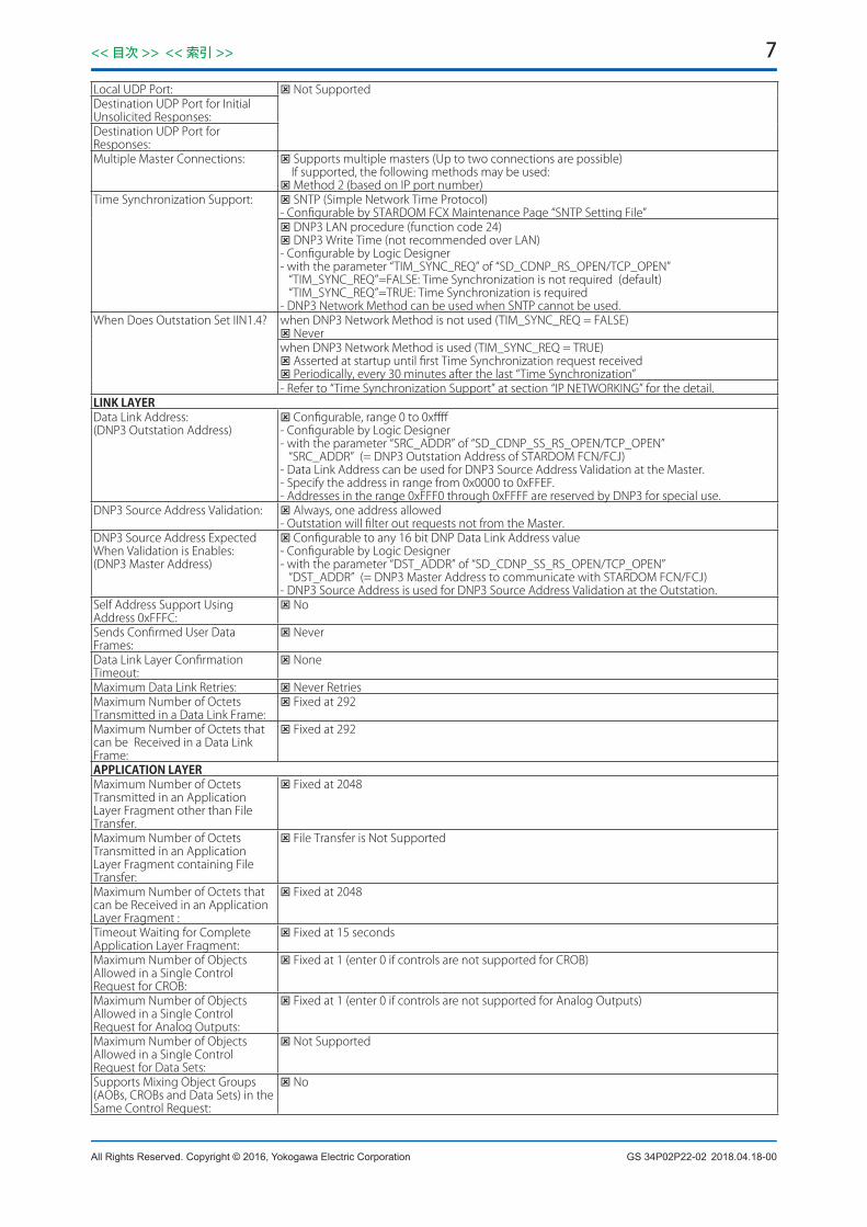
Local UDP Port: Not SupportedDestination UDP Port for Initial Unsolicited Responses:Destination UDP Port for Responses:Multiple Master Connections: Supports multiple masters (Up to two connections are possible)
If supported, the following methods may be used: Method 2 (based on IP port number)
Time Synchronization Support: SNTP (Simple Network Time Protocol)- Configurable by STARDOM FCX Maintenance Page “SNTP Setting File” DNP3 LAN procedure (function code 24) DNP3 Write Time (not recommended over LAN)- Configurable by Logic Designer- with the parameter “TIM_SYNC_REQ” of “SD_CDNP_RS_OPEN/TCP_OPEN” “TIM_SYNC_REQ”=FALSE: Time Synchronization is not required (default) “TIM_SYNC_REQ”=TRUE: Time Synchronization is required- DNP3 Network Method can be used when SNTP cannot be used.
When Does Outstation Set IIN1.4? when DNP3 Network Method is not used (TIM_SYNC_REQ = FALSE) Neverwhen DNP3 Network Method is used (TIM_SYNC_REQ = TRUE) Asserted at startup until first Time Synchronization request received Periodically, every 30 minutes after the last “Time Synchronization”- Refer to “Time Synchronization Support” at section “IP NETWORKING” for the detail.
LINKLAYERData Link Address:(DNP3 Outstation Address)
Configurable, range 0 to 0xffff- Configurable by Logic Designer- with the parameter “SRC_ADDR” of “SD_CDNP_SS_RS_OPEN/TCP_OPEN” “SRC_ADDR” (= DNP3 Outstation Address of STARDOM FCN/FCJ)- Data Link Address can be used for DNP3 Source Address Validation at the Master.- Specify the address in range from 0x0000 to 0xFFEF.- Addresses in the range 0xFFF0 through 0xFFFF are reserved by DNP3 for special use.
DNP3 Source Address Validation: Always, one address allowed- Outstation will filter out requests not from the Master.
DNP3 Source Address Expected When Validation is Enables:(DNP3 Master Address)
Configurable to any 16 bit DNP Data Link Address value- Configurable by Logic Designer- with the parameter “DST_ADDR” of “SD_CDNP_SS_RS_OPEN/TCP_OPEN” “DST_ADDR” (= DNP3 Master Address to communicate with STARDOM FCN/FCJ)- DNP3 Source Address is used for DNP3 Source Address Validation at the Outstation.
Self Address Support Using Address 0xFFFC:
No
Sends Confirmed User Data Frames:
Never
Data Link Layer Confirmation Timeout:
None
Maximum Data Link Retries: Never RetriesMaximum Number of Octets Transmitted in a Data Link Frame:
Fixed at 292
Maximum Number of Octets that can be Received in a Data Link Frame:
Fixed at 292
APPLICATIONLAYERMaximum Number of Octets Transmitted in an Application Layer Fragment other than File Transfer.
Fixed at 2048
Maximum Number of Octets Transmitted in an Application Layer Fragment containing File Transfer:
File Transfer is Not Supported
Maximum Number of Octets that can be Received in an Application Layer Fragment :
Fixed at 2048
Timeout Waiting for Complete Application Layer Fragment:
Fixed at 15 seconds
Maximum Number of Objects Allowed in a Single Control Request for CROB:
Fixed at 1 (enter 0 if controls are not supported for CROB)
Maximum Number of Objects Allowed in a Single Control Request for Analog Outputs:
Fixed at 1 (enter 0 if controls are not supported for Analog Outputs)
Maximum Number of Objects Allowed in a Single Control Request for Data Sets:
Not Supported
Supports Mixing Object Groups (AOBs, CROBs and Data Sets) in the Same Control Request:
No
2018.04.18-00

8<< 目次 >> << 索引 >>
All Rights Reserved. Copyright © 2016, Yokogawa Electric Corporation GS 34P02P22-02
Control Status Codes Supported: 1 – TIMEOUT 2 – NO_SELECT 3 – FORMAT_ERROR 4 – NOT_SUPPORTED 5 – ALREADY_ACTIVE 6 – HARDWARE_ERROR 7 – LOCAL 8 – TOO_MANY_OBJS 9 – NOT_AUTHORIZED 10 – AUTOMATION_INHIBIT 11 – PROCESSING_LIMITED 12 – OUT_OF_RANGE 13 – DOWNSTREAM_LOCAL 14 – ALREADY_COMPLETE 15 – BLOCKED 16 – CANCELLED 17 – BLOCKED_OTHER_MASTER 18 – DOWNSTREAM_FAIL 126 – RESERVED 127 – UNDEFINED
ITEMSFOROUTSTATIONSTimeout Waiting for Application Confirm of Solicited Response Message:
Configurable, range 10 to 600 seconds (default = 10 (sec))- with the parameter “APPL_CNF_TOUT” of “SD_CDNP_SS_RS_OPEN/TCP_OPEN”
How often is Time Synchronization Required from the Master:
Never needs time Periodically, between 100 and 1800 seconds- IIN1.4 will be set at startup and every 30 minutes (1800 seconds) after the last “Time Synchronization”, when the parameter “TIM_SYNC_REQ” of “SD_SDNP_SS_RS_OPEN/TCP_OPEN” is set to “TRUE”
Device Trouble Bit IIN1.6: Never usedFile Handle Timeout: Not Applicable, Files Not SupportedEvent Buffer Overflow Behavior: Discard the oldest event
Discard the newest event- Selectable with the parameter “NWST_EVT_DEL” of “SD_SDNP_SS_RS_OPEN/TCP_OPEN” “NWST_EVT_DEL”=FALSE: Discard the Oldest Event (default) “NWST_EVT_DEL”=TRUE: Discard the Newest Event
Event Buffer Organization: Per Object Group.Event buffer sizes are configurable for each Object Group - at range from 0 to 135,000 - Configurable with the following parameters of “SD_CDNP_SS_RS_OPEN/TCP_OPEN” “BI_EVT_SIZE” - Binary Input event buffer size (default = 500) “CT_EVT_SIZE” - Binary Counter event buffer size (default = 500) “AI_EVT_SIZE” - Analog Input event buffer size (default = 500)- The flowing parameters are effective with “SD_CDNP_SS_ASSIGN2” POU. “BO_EVT_SIZE” - Binary Output event buffer size (default = 0) “AO_EVT_SIZE” - Analog Output event buffer size (default = 0) “OSTR_EVT_SIZE” - Octet String event buffer size (default = 0) (range from 0 to 67,500) “FRZ_CT_EVT_SIZE” - Frozen Counter event buffer size (default = 0)Within the following conditions;- Maximum event size of the all event buffers for all connections is 135,000.- Maximum event size for CPU Module with 64 MB or less main memory, with Java in use is 3500.- However, the octet string event size will be doubled and added to the total event size.
Sends Multi-Fragment Responses: Yes No<for event data>- The maximum number of the application layer multi-fragment is configurable with the parameter “FRGMNT_RESP” of “SD_CDNP_RS_OPEN/TCP_OPEN” “FRGMNT_RESP”=1 to 100: Maximum number of multi-fragment (1:Single-Fragment) “FRGMNT_RESP”=0: Multi-Fragment for all requested event (default)- for “SD_CDNP_SS_RS_OPEN” “FRGMNT_RESP”=UINT#16#8000: Auto configuration maximum number by baud rate also can be used.<for static data>- Static data can be sent with multi-fragment responses, if it is necessary.
Last Fragment Confirmation: AlwaysDNP Command Settings Preserved Through a Device Reset:
Assign Class Analog Deadbands
Supports configuration signature: Not Supported
2018.04.18-00

9<< 目次 >> << 索引 >>
GS 34P02P22-02All Rights Reserved. Copyright © 2016, Yokogawa Electric Corporation
Requests Application Confirmation: For event responses: ● Yes ○ No ○ ConfigurableFor non-final fragments: ● Yes ○ No ○ Configurable
Supports Clock Management Yes (support both DNP3 time synchronization and SNTP)OUTSTATIONUNSOLICITEDRESPONSESUPPORTSupports Unsolicited Reporting: Yes
No Configurable, selectable from On or Off- with the parameter “UNSOL_ALLOWED” of “SD_CDNP_SS_RS_OPEN/TCP_OPEN” “UNSOL_ALLOWED”=TRUE: Unsolicited Response mode is ON “UNSOL_ALLOWED”=FALSE: Unsolicited Response mode is OFF (default)Note for Serial Connection- Unsolicited Response must be used with the Point-to-point connectionNote for Serial Communication Modules- “Full-duplex” should be selected for Duplex Operation by Resource Configurator
Master Data Link Address: Configurable, range 0 to 0xFFEF- The same master address is used for both solicited and unsolicited responses with the parameter “DST_ADDR” of “SD_CDNP_SS_RS_OPEN/TCP_OPEN”.- Addresses in the range 0xFFF0 through 0xFFFF are reserved by DNP3 for special use.
Unsolicited Response Confirmation Timeout:
Configurable, range 10 to 600 seconds (default=10 (sec))- The same value of “Application Layer Confirmation” is used with the parameter “APPL_CNF_TOUT” of “SD_CDNP_SS_RS_OPEN/TCP_OPEN”
Number of Unsolicited Retries: Configurable, range 0 to 10 (default=3)- with the parameter “UNSOL_RETRY_NUM” of “SD_CDNP_SS_RS_OPEN/TCP_OPEN”
OUTSTATIONUNSOLICITEDRESPONSETRIGGERCONDITIONSNumber of Class 1 Events: Configurable, range 1 to 100 (default=5)
- with the parameter “UNSOL_C1_TRG_NUM” of “SD_CDNP_SS_RS_OPEN/TCP_OPEN”Number of Class 2 Events: Configurable, range 1 to 100 (default=5)
- with the parameter “UNSOL_C2_TRG_NUM” of “SD_CDNP_SS_RS_OPEN/TCP_OPEN”Number of Class 3 Events: Configurable, range 1 to 100 (default=5)
- with the parameter “UNSOL_C3_TRG_NUM” of “SD_CDNP_SS_RS_OPEN/TCP_OPEN”Total Number Events from Any Class:
Total Number of Events not used to trigger Unsolicited Responses
Hold Time After Class 1 Event: Configurable, range 0 to 10 seconds (default=5 seconds)- with the parameter “UNSOL_C1_TRG_HOLD” of “SD_CDNP_SS_RS_OPEN/TCP_OPEN”
Hold Time After Class 2 Event: Configurable, range 0 to 10 seconds (default=5 seconds)- with the parameter “UNSOL_C2_TRG_HOLD” of “SD_CDNP_SS_RS_OPEN/TCP_OPEN”
Hold Time After Class 3 Event: Configurable, range 0 to 10 seconds (default=5 seconds)- with the parameter “UNSOL_C3_TRG_HOLD” of “SD_CDNP_SS_RS_OPEN/TCP_OPEN”
Hold Time After Event Assigned to Any Class:
Class events not used to trigger Unsolicited Responses
Retrigger Hold Time: Hold-time timer will be retriggered for each new event detected (may get more changes in next response)
Other Unsolicited Response Trigger Conditions:
NONE
INDIVIDUALFIELDOUTSTATIONPARAMETERSAnalog Data Type: Configurable by Logic Designer;
- with the parameter “ANLG_TYPE” of “SD_CDNP_SS_ASSIGN” “ANLG_TYPE”=0: REAL (Single-Precision Floating Point) (default) “ANLG_TYPE”=1: DINT (32-Bit Integer)
Detail Data Types: Configurable by Logic Designer;- with the following parameters of “SD_CDNP_SS_ASSIGN2”“CT_MAX_INDEX” and “CT16/CT32_OFFSET” - Binary Counter data area“AI_MAX_INDEX” and “AI16/AI32/AISF/AIDF_OFFSET” - Analog Input data area“AO_MAX_INDEX” and “AO16/AO32/AOSF/AODF_OFFSET” - Analog Output data area
Analog Input Deadbands: Configurable - All Points - as the Default Deadband Value;- with the parameter “ANLG_DBND_VAL” of “SD_CDNP_SS_ASSIGN” (default = 0.0) Fixed at 0.0 – All Points – with “SD_CDNP_SS_ASSIGN2” Configurable - Per Point - by “SD_CDNP_S_DBND”- DNP3 Analog Input Deadband Value Setting POU (SD_CDNP_S_DBND); Configurable - Per Point - by Master
Time Value for all DNP3 protocol time stamps reported and time synchronization messages:
Configurable, selectable from “Local Time” or “UTC”- by the following bit of the parameter “OPTION” of “SD_CDNP_SS_ASSIGN/ASSIGN2” “OPTION”=DWORD#16#00000001: UTC “OPTION”=DWORD#16#00000000: Local Time (default)- The UTC time base has been used for the effective date since January 1, 2008.
Unsolicited Response: Configurable – Per Connection by “SD_CDNP_SS_RS/TCP_OPEN” with “SD_CDNP_SS_ ASSIGN2”
2018.04.18-00

10<< 目次 >> << 索引 >>
All Rights Reserved. Copyright © 2016, Yokogawa Electric Corporation GS 34P02P22-02
Event Class Assign: Configurable - All Points - as the default event class for each data type;
- with the following parameters of “SD_CDNP_SS_ASSIGN/ASSIGN2” “BI_EVT_CLASS”=0/1/2/3 - Binary Input event class (default = 1) “CT_EVT_CLASS”=0/1/2/3 - Binary Counter event class (default = 3) “AI_EVT_CLASS”=0/1/2/3 - Analog Input event class (default = 2)- with the following parameters of “SD_CDNP_SS_ASSIGN2” “BO_EVT_CLASS”=0/1/2/3 - Binary Output event class (default = 0) “AO_EVT_CLASS”=0/1/2/3 - for Analog Output event class (default = 0) “OSTR_EVT_CLASS”=0/1/2/3 - for Octet String event class (default = 0) “FRZ_CT_EVT_CLASS”=0/1/2/3 - Frozen Counter event class (default=0) Configurable - Per Point - with “SD_CDNP_S_EVTC” Configurable - Per Point - by Master
Preservation of Class Assign through a Device Reset:
No - (If any of Class Assign are written by a Master, the Master will have to write them again.) Yes - (with “SC_CDNP_S_EVTC”)
Preservation of Analog Input Deadband Settings Per Point through a Device Reset:
No - (If any of Analog Input Deadbands are written by a Master, the Master will have to write them again) Yes - (with “SD_CDNP_S_DBND”)
File Handling: Not Supported
Control Relay Output Block (CROB) Operation:
Yes
Analog Output Block (AOB) Operation:
Yes
Latch model CROB Operation Attribute:
Configurable - All Points - as the default Latch model CROB operation attribute;- with the parameter “CROB_ATTRIB” of “SD_CDNP_SS_ASSIGN/ASSIGN2” “CROB_ATTRIB”=0: No operation is enabled (default) “CROB_ATTRIB”=1: Latch ON/OFF operation is enabled Configurable - Per Point- with the parameter “ATTRIB” of “SD_CDNP_S_CROB” “ATTRIB”=0: No operation is enabled (default) “ATTRIB”=1: Latch ON/OFF operation is enabled
Pulse Model CROB Operation Execution:
Definable - Per Point- with “SD_CDNP_S_CROB_PULSE” (effective with “SD_CDNP_SS_ASSIGN2”)
Binary Output Change Event generating by remote operation:
Selectable by Logic Designer;- by the following bit of the parameter “OPTION” of “SD_CDNP_SS_ASSIGN2” “OPTION”=DWORD#16#00000020: Output events will be generated by Remote operation of CROB commands or Analog output operation commands from the master station.This option will be effective with following configurations.- BO/AO_EVT_CLASS != 0 (by SD_CDNP_SS_ASSIGN2 POU or SD_CDNP_S_EVTC POU)- BO/AO_EVT_SIZE != 0 (by SD_CDNP_SS_RS_OPEN or SD_CDNP_SS_TCP_OPEN POU)And for Binary Outputs, “Latch Model CROB Operation Attribute” or “Pulse Model CROB Operation Command Executing POU” must be defined.
Analog Output Change Event generating by remote operation:
Binary Counter Change Event generating by remote Freeze and Clear operation:
Selectable by Logic Designer;- by the following bit of the parameter “OPTION” of “SD_CDNP_SS_ASSIGN2” “OPTION”=DWORD#16#00000040: Binary Counter Change events will be generated by Remote Freeze and Clear operation commands from the master station. This option will be effective with following configuration.- “CT_EVT_CLASS” != 0 (by SD_CDNP_SS_ASSIGN2 POU or SD_CDNP_S_EVTC POU)- “CT_EVT_SIZE” != 0 (by SD_CDNP_SS_RS_OPEN or SD_CDNP_SS_TCP_OPEN POU)
Octet String Change Event generating by remote operation:
Selectable by Logic Designer;- by the following bit of the parameter “OPTION” of “SD_CDNP_SS_ASSIGN2” “OPTION”=DWORD#16#00000080: Octet String Change events will be generated by Remote operation commands from the master station.This option will be effective with following configuration.- “OSTR_EVT_CLASS” != 0 (by SD_CDNP_SS_ASSIGN2 POU or SD_CDNP_S_EVTC POU)- “OSTR_EVT_SIZE” != 0 (by SD_CDNP_SS_RS_OPEN or SD_CDNP_SS_TCP_OPEN POU)
This Device Properties is referred to “DNP3 SPECIFICATION DEVICE PROFILE, Version 2016, April-2016.”
2017.04.27-00

11<< 目次 >> << 索引 >>
GS 34P02P22-02All Rights Reserved. Copyright © 2016, Yokogawa Electric Corporation
● CapabilitiesforDeviceDatabaseSINGLE-BITBINARYINPUTPOINTSStatic(Steady-State)ObjectNumber:1EventObjectNumber:2Static Variation reported when variation 0 requested or in response to Class polls
Variation 2 - with flag
Event Variation reported when variation 0 requested or in response to Class polls
<with “SD_CDNP_SS_ASSIGN”> Variation 2 - with absolute time
<with “SD_CDNP_SS_ASSIGN2”> Variation 1 - without time (optional) Variation 2 - with absolute time (default)- “without time” is selectable with the following bit of the parameter “OPTION” of “SD_CDNP_SS_ASSIGN2”“OPTION” = DWORD#16#00004000: All event data without time stamp bit
Event reporting mode All eventsBinary Inputs included in Class 0 response:
Always
Binary Inputs Event Buffer Organization:
Configurable, range 0 to 135000 (default=500)- with the parameter “BI_EVT_SIZE“ of “SD_CDNP_SS_RS_OPEN/TCP_OPEN”- Total maximum event size for all data types and all connections is 135000.
BINARYOUTPUTSTATUSANDCONTROLRELAYOUTPUTBLOCKBinaryOutputStatusObjectNumber:10BinaryOutputEventObjectNumber:11CROBObjectNumber:12Minimum pulse time allowed with Trip, Close and Pulse On/Off commands.
Fixed at 0 ms (accuracy will be the control task execution period)- However, the 0-ms On-time for Trip/Close/Pulse On commands and the 0-ms Off-time for Trip/ Close/Pulse Off commands are not allowed.
Maximum pulse time allowed with Trip, Close and Pulse On/Off commands.
Fixed at 60000 ms (accuracy will be the control task execution period)
Binary Output Status included in Class 0 response:
Always
Static Variation reported when variation 0 requested or in response to Class polls:
Variation 2 - output status with flags
Event Variation reported when variation 0 requested or in response to Class polls:
<with “SD_CDNP_SS_ASSIGN”> Variation 2 - status with time
<with “SD_CDNP_SS_ASSIGN2”> Variation 1 – status without time (optional) Variation 2 – status with time (default)- “without time” is selectable with the following bit of the parameter “OPTION” of “SD_CDNP_SS_ASSIGN2”“OPTION” = DWORD#16#00004000: All event data without time stamp bit
Event reporting mode: All eventsMaximum Time between Select and Operate:
Configurable, range from 1 to 600 seconds (default=5)- with the parameter “SBO_SEL_TOUT” of “SD_CDNP_SS_RS_OPEN/TCP_OPEN”- SBO operation is effective with “SD_CDNP_SS_ASSIGN2”
Binary Outputs Event Buffer Organization:
Configurable, range 0 to 135000 (default=0)- with the parameter “BO_EVT_SIZE“ of “SD_CDNP_SS_RS_OPEN/TCP_OPEN”- Total maximum event size for all data types and all connections is 135000.
COUNTERS/FROZENCOUNTERSStaticCounterObjectNumber:20StaticFrozenCounterObjectNumber:21CounterEventObjectNumber:22FrozenCounterEventObjectNumber:23Static Counter Variation reported when variation 0 requested or in response to Class polls
<with “SD_CDNP_SS_ASSIGN”> Variation 1 - 32-bit with flag
<with “SD_CDNP_SS_ ASSIGN2”> Based on point index (Variation 1 or 2)
Counter Event Variation reported when variation 0 requested or in response to Class polls
<with “SD_CDNP_SS_ASSIGN”> Variation 5 - 32-bit with flag and time
<with “SD_CDNP_SS_ASSIGN2”> Based on point index (Variation 5 or 6) (default) Based on point index (Variation 1 or 2) (without time - optional)- “without time” is selectable with the following bit of the parameter “OPTION” of “SD_CDNP_SS_ASSIGN2”“OPTION” = DWORD#16#00004000: All event data without time stamp bit
2017.04.27-00

12<< 目次 >> << 索引 >>
All Rights Reserved. Copyright © 2016, Yokogawa Electric Corporation GS 34P02P22-02
Counter included in Class 0 response:
Always
Counter Event reporting mode All eventsStatic Frozen Counter Variation reported when variation 0 requested or in response to Class polls:
<with “SD_CDNP_SS_ASSIGN2”> Based on point index (Variation 1 or 2)- Frozen Counter can be handled with “SD_CDNP_SS_ASSIGN2”
Frozen Counter Event Variation reported when variation 0 requested or in response to Class polls:
<with “SD_CDNP_SS_ASSIGN2”> Based on point index (Variation 5 or 6) (default) Based on point index (Variation 1 or 2) (without time - optional)- “without time” is selectable with the following bit of the parameter “OPTION” of “SD_CDNP_SS_ASSIGN2”“OPTION” = DWORD#16#00004000: All event data without time stamp bit
Frozen Counters included in Class 0 response:
Always (default) Never (optional)- “Never” can be selected by following bit of the parameter “OPTION” of “SD_CDNP_SS_ASSIGN2”“OPTION” = DWORD#16#00000100: Frozen counter class 0 response stop bit- Frozen Counter can be handled with “SD_CDNP_SS_ASSIGN2”
Frozen Counter Event reporting mode:
All frozen events- Frozen Counter Event can be handled with “SD_CDNP_SS_ASSIGN2”
Counter Roll Over at: <with “SD_CDNP_SS_ASSIGN”> 32 Bits (4,294,967,295)
<with “SD_CDNP_SS_ASSIGN2”> Based on point index (16 Bits or 32 Bits)
Counter frozen by means of: Master Request- Frozen command can be handled with “SD_CDNP_SS_ASSIGN2”
Counters Event Buffer Organization:
Configurable, range 0 to 135000 (default=500)- with the parameter “CT_EVT_SIZE” of “SD_CDNP_SS_RS_OPEN/TCP_OPEN”- Total maximum event size for all data types is 135000.
Frozen Counters Event Buffer Organization:
Configurable, range 0 to 135000 (default=0)- with the parameter “FRZ_CT_EVT_SIZE” of “SD_CDNP_SS_RS_OPEN/TCP_OPEN”- Total maximum event size for all data types and all connections is 135000.- Frozen Counter Event can be handled with “SD_CDNP_SS_ASSIGN2”
Reports counter events for change of value:
Yes for all counters No for all counters- Selectable with the parameter “CT_EVT_CLASS” of “SD_CDNP_SS_ASSIGN/ASSIGN2” and
“CT_EVT_SIZE” of “SD_CNDP_SS_RS/TCP_OPEN”. Configurable, based on point Index- Configurable with the parameter “EVT_CLASS” of “SD_CDNP_S_EVTC” or assign class
command from SCADA/Master.ANALOGINPUTPOINTSStatic(Steady-State)ObjectNumber:30EventObjectNumber:32AnalogInputDeadbandObjectNumber:34Static Variation reported when variation 0 requested or in response to Class polls:
<with “SD_CDNP_SS_ASSIGN”> Variation 1 - 32-bit with flag (DINT) Variation 5 - single-precision floating point with flag (REAL)- “DINT” or “REAL” is selectable with the parameter “ANLG_TYPE” of “SC_CDNP_ASSIGN”<with “SD_CDNP_SS_ASSIGN2”> Based on point index (Variation 1, 2 or 5)
Event Variation reported when variation 0 requested or in response to Class polls:
<with “SD_CDNP_SS_ASSIGN”> Variation 3 - 32-bit with time (DINT) Variation 7 - single-precision floating point with time (REAL)- “DINT” or “REAL” is selectable with the parameter “ANLG_TYPE” of “SC_CDNP_ASSIGN”<with “SD_CDNP_SS_ASSIGN2”> Based on point index (Variation 3, 4, 7 or 8) (default) Based on point index (Variation 1, 2, 5 or 6) (without time - optional)- “without time” is selectable with the following bit of the parameter “OPTION” of “SD_CDNP_
SS_ASSIGN2”“OPTION” = DWORD#16#00004000: All event data without time stamp bit
Event reporting mode All eventsAnalog Inputs included in Class 0 response:
Always
How Deadbands are set: Configurable through DNP Configurable via other means- Configurable with "SD_CDNP_S_DBND" POU for each point with SD_CDNP_SS_ASSIGN2 POU.- Configurable with the parameter "ANLG_DBND_VAL" of SD_CDBP_SS_ASSIGN POU for all points.
Analog Deadband Algorithm: Simple - just compare the difference from the previous reported valueAnalog Inputs Event Buffer Organization:
Configurable, range 0 to 135000 (default=500)- with the parameter “AI_EVT_SIZE” of “SD_CDNP_SS_RS_OPEN/TCP_OPEN”- Total maximum event size for all data types and all connections is 135000.
2017.04.27-00

13<< 目次 >> << 索引 >>
GS 34P02P22-02All Rights Reserved. Copyright © 2016, Yokogawa Electric Corporation
ANALOGOUTPUTSTATUSANDANALOGOUTPUTCONTROLBLOCKAnalogOutputStatusObjectNumber:40AnalogOutputControlBlockObjectNumber:41AnalogOutputEventObjectNumber:42Static Analog Output Status Variation reported when variation 0 requested or in response to Class polls:
<with “SD_CDNP_SS_ASSIGN”> Variation 1 - 32-bit with flag (DINT) Variation 3 - single-precision floating point with flag (REAL)- “DINT” or “REAL” is selectable with the parameter “ANLG_TYPE” of “SC_CDNP_ASSIGN”
<with “SD_CDNP_SS_ASSIGN2”> Based on point index (Variation 1, 2, 3 or 4)
Analog Output Status included in Class 0 response:
Always
Event Variation reported when variation 0 requested or in response to Class polls:
<with “SD_CDNP_SS_ASSIGN”> Variation 3 - 32-bit with time (DINT) Variation 7 - single-precision floating point with time (REAL)- “DINT” or “REAL” is selectable with the parameter “ANLG_TYPE” of “SC_CDNP_ASSIGN”<with “SD_CDNP_SS_ASSIGN2”> Based on point index (Variation 3, 4, 7 or 8) (default) Based on point index (Variation 1, 2, 5 or 6) (without time - optional)- “without time” is selectable with the following bit of the parameter “OPTION” of “SD_CDNP_
SS_ASSIGN2”“OPTION” = DWORD#16#00004000: All event data without time stamp bit
Event reporting mode: All eventsMaximum Time between Select and Operate:
Configurable, range from 1 to 600 seconds (default=5)- with the parameter “SBO_SEL_TOUT” of “SD_CDNP_SS_RS_OPEN/TCP_OPEN”- SBO operation is effective with “SD_CDNP_SS_ASSIGN2”
Analog Outputs Event Buffer Organization:
Configurable, range 0 to 135000 (default=0)- with the parameter “AO_EVT_SIZE“ of “SD_CDNP_SS_RS_OPEN/TCP_OPEN”- Total maximum event size for all data types and all connections is 135000.
OCTETSTRINGPOINTSStatic(Steady-State)ObjectNumber:110110EventObjectNumber:111Event reporting mode: All events
- Octet String Event can be handled with “SD_CDNP_SS_ASSIGN2”Octet Strings included in Class 0 response:
Always (default) Never (optional)- “Never” is selectable with the following bit of the parameter “OPTION” of “SD_CDNP_SS_
ASSIGN2”“OPTION” = DWORD#16#00000400: Octet string class 0 response stop bit
- Octet String can be handled with “SD_CDNP_SS_ASSIGN2”Maximum number of octets that can be handled in an Octet String Data:
Fixed at 32-Octets- Octet String can be handled with ASSIGN2 POU
Octet Strings Event Buffer Organization:
Configurable, range 0 to 135000 (default=0)- with the parameter “OSTR_EVT_SIZE” of “SD_CDNP_SS_RS_OPEN/TCP_OPEN”- Total maximum event size for all data types and all connections is 135000.- Octet String Event can be handled with “SD_CDNP_SS_ASSIGN2”
Object Group Selection Fixed, group 110 for all objects
This Capabilities for Device Database is referred to “DNP3 SPECIFICATION DEVICE PROFILE Version 2016, April-2016."
2017.04.27-00

14<< 目次 >> << 索引 >>
All Rights Reserved. Copyright © 2016, Yokogawa Electric Corporation GS 34P02P22-02
● ImplementationTable
DNPOBJECTGROUP&VARIATION REQUEST(FCN/FCJwillparse)
RESPONSE(FCN/FCJwillrespond)
GroupNumber
VariationNumber Description FunctionCodes
(dec)QualifierCodes
(hex)
FunctionCodes(dec)
QualifierCodes(hex)
1 0
Binary Input - Any variation(Variation 0 is used to request default variation)
1 (read),22 (assign class)
00, 01 (start-stop),06 (all),07, 08 (limited qty),17, 28 (index)
1 1 Binary Input - Packed format
1 (read) 00, 01 (start-stop),06 (all),07, 08 (limited qty),17, 28 (index)
129 (response)
00, 01 (start-stop),17, 28 (index)
1 2 Binary Input - With flags
1 (read) 00, 01 (start-stop),06 (all),07, 08 (limited qty),17, 28 (index)
129 (response)
00, 01 (start-stop),17, 28 (index)
2 0
Binary Input Change Event - Any variation(Variation 0 is used to request default variation)
1 (read) 06 (all),07, 08 (limited qty)
2 1 Binary Input Change Event without Time
1 (read) 06 (all),07, 08 (limited qty)
129 (response)130 (unsol. resp.)
17, 28 (index)
2 2 Binary Input Change Event - With absolute time
1 (read) 06 (all),07, 08 (limited qty)
129 (response)130 (unsol. resp.)
17, 28 (index)
10 0
Binary Output Status - Any variation(Variation 0 is used to request default variation)
1 (read)22 (assign class)
00, 01 (start-stop),06 (all),07, 08 (limited qty),17, 28 (index)
10 1 Binary Output Status - Packed format
1 (read) 00, 01 (start-stop),06 (all),07, 08 (limited qty),17, 28 (index)
129 (response)
00, 01 (start-stop),17, 28 (index)
10 2 Binary Output Status - Output status with flags
1 (read) 00, 01 (start-stop),06 (all),07, 08 (limited qty),17, 28 (index)
129 (response)
00, 01 (start-stop),17, 28 (index)
11 0
Binary Output Event - Any variation(Variation 0 is used to request default variation)
1 (read) 00, 01 (start-stop),06 (all)
11 1 Binary Output Event - Status without time
1 (read) 00, 01 (start-stop),06 (all)
129 (response)130 (unsol. resp.)
17, 28 (index)
11 2 Binary Output Event - Status with time
1 (read) 00, 01 (start-stop),06 (all)
129 (response)130 (unsol. resp.)
17, 28 (index)
12 1Binary Output Command - Control relay outputblock (CROB)
03 (select),04 (operate),05 (direct perate),06 (direct op, no ack)
17, 28 (index) 129 (response)
17, 28 (index)
20 0Counter – Any variation(Variation 0 is used to request default variation)
1 (read),22 (assign class)
00, 01 (start-stop),06 (all),07, 08 (limited qty),17, 28 (index)
7 (freeze),8 (freeze no ack),9 (freeze & clear),10 (frz & clr, no ack)
00, 01 (start-stop),06 (all)
20 1 Counter - 32-bit with flag
1 (read) 00, 01 (start-stop),06 (all),07, 08 (limited qty),17, 28 (index)
129 (response)
00, 01 (start-stop),17, 28 (index)
2016.07.15-00

15<< 目次 >> << 索引 >>
GS 34P02P22-02All Rights Reserved. Copyright © 2016, Yokogawa Electric Corporation
DNPOBJECTGROUP&VARIATION REQUEST(FCN/FCJwillparse)
RESPONSE(FCN/FCJwillrespond)
GroupNumber
VariationNumber Description FunctionCodes
(dec)QualifierCodes
(hex)
FunctionCodes(dec)
QualifierCodes(hex)
20 2 Counter - 16-bit with flag
1 (read) 00, 01 (start-stop),06 (all),07, 08 (limited qty),17, 28 (index)
129 (response)
00, 01 (start-stop),17, 28 (index)
20 5 Counter - 32-bit without flag
1 (read) 00, 01 (start-stop),06 (all),07, 08 (limited qty),17, 28 (index)
129 (response)
00, 01 (start-stop),17, 28 (index)
20 6 Counter - 16-bit without flag
1 (read) 00, 01 (start-stop),06 (all),07, 08 (limited qty),17, 28 (index)
129 (response)
00, 01 (start-stop),17, 28 (index)
21 0Frozen Counter -Any variation(Variation 0 is used to request default variation)
1 (read)22 (assign class)
00, 01 (start-stop),06 (all),07, 08 (limited qty),17, 28 (index)
21 1 Frozen Counter - 32-bit with flag
1 (read) 00, 01 (start-stop),06 (all),07, 08 (limited qty),17, 28 (index)
129 (response)
00, 01 (start-stop),17, 28 (index)
21 2 Frozen Counter - 16-bit with flag
1 (read) 00, 01 (start-stop),06 (all),07, 08 (limited qty),17, 28 (index)
129 (response)
00, 01 (start-stop),17, 28 (index)
21 5 Frozen Counter - 32-bit with flag and time
1 (read) 00, 01 (start-stop),06 (all),07, 08 (limited qty),17, 28 (index)
129 (response)
00, 01 (start-stop),17, 28 (index)
21 6 Frozen Counter - 16-bit with flag and time
1 (read) 00, 01 (start-stop),06 (all),07, 08 (limited qty),17, 28 (index)
129 (response)
00, 01 (start-stop),17, 28 (index)
21 9 Frozen Counter - 32-bit without flag
1 (read) 00, 01 (start-stop),06 (all),07, 08 (limited qty),17, 28 (index)
129 (response)
00, 01 (start-stop),17, 28 (index)
21 10 Frozen Counter -16-bit without flag
1 (read) 00, 01 (start-stop),06 (all),07, 08 (limited qty),17, 28 (index)
129 (response)
00, 01 (start-stop),17, 28 (index)
22 0
Counter Change Event - Any variation(Variation 0 is used to request default variation)
1 (read) 06 (all),07, 08 (limited qty)
22 1 Counter Change Event - 32-bit with flag
1 (read) 06 (all),07, 08 (limited qty)
129 (response)130 (unsol. resp.)
17, 28 (index)
22 2 Counter Change Event - 16-bit with flag
1 (read) 06 (all),07, 08 (limited qty)
129 (response)130 (unsol. resp.)
17, 28 (index)
22 5 Counter Change Event -32-bit with flag and time
1 (read) 06 (all),07, 08 (limited qty)
129 (response)130 (unsol. resp.)
17, 28 (index)
22 6 Counter Change Event -16-bit with flag and time
1 (read) 06 (all),07, 08 (limited qty)
129 (response)130 (unsol. resp.)
17, 28 (index)
23 0
Frozen Counter Change Event - Any variation(Variation 0 is used to request default variation)
1 (read) 06 (all),07, 08 (limited qty)
23 1 Frozen Counter Change Event - 32-bit with flag
1 (read) 06 (all),07, 08 (limited qty)
129 (response)
17, 28 (index)
23 2 Frozen Counter Change Event - 16-bit with flag
1 (read) 06 (all),07, 08 (limited qty)
129 (response)
17, 28 (index)
23 5 Frozen Counter Change Event - 32-bit with flag and time
1 (read) 06 (all),07, 08 (limited qty)
129 (response)
17, 28 (index)
2016.07.15-00

16<< 目次 >> << 索引 >>
All Rights Reserved. Copyright © 2016, Yokogawa Electric Corporation GS 34P02P22-02
DNPOBJECTGROUP&VARIATION REQUEST(FCN/FCJwillparse)
RESPONSE(FCN/FCJwillrespond)
GroupNumber
VariationNumber Description FunctionCodes
(dec)QualifierCodes
(hex)
FunctionCodes(dec)
QualifierCodes(hex)
23 6 Frozen Counter Change Event - 16-bit with flag and time
1 (read) 06 (all),07, 08 (limited qty)
129 (response)
17, 28 (index)
30 0Analog Input - Any variation(Variation 0 is used to request default variation)
1 (read),22 (assign class)
00, 01 (start-stop),06 (all),07, 08 (limited qty),17, 28 (index)
30 1 Analog Input - 32-bit with flag
1 (read) 00, 01 (start-stop),06 (all),07, 08 (limited qty),17, 28 (index)
129 (response)
00, 01 (start-stop),17, 28 (index)
30 2 Analog Input - 16-bit with flag
1 (read) 00, 01 (start-stop),06 (all),07, 08 (limited qty),17, 28 (index)
129 (response)
00, 01 (start-stop),17, 28 (index)
30 3 Analog Input - 32-bit without flag
1 (read) 00, 01 (start-stop),06 (all),07, 08 (limited qty),17, 28 (index)
129 (response)
00, 01 (start-stop),17, 28 (index)
30 4 Analog Input -16-bit without flag
1 (read) 00, 01 (start-stop),06 (all),07, 08 (limited qty),17, 28 (index)
129 (response)
00, 01 (start-stop),17, 28 (index)
30 5 Analog Input - Single-precisionfloating point with flag
1 (read) 00, 01 (start-stop),06 (all),07, 08 (limited qty),17, 28 (index)
129 (response)
00, 01 (start-stop),17, 28 (index)
30 6 Analog Input - Double-precisionfloating point with flag
1 (read) 00, 01 (start-stop),06 (all),07, 08 (limited qty),17, 28 (index)
129 (response)
00, 01 (start-stop),17, 28 (index)
32 0
Analog Input Change Event - Any variation(Variation 0 is used to request default variation)
1 (read) 06 (all),07, 08 (limited qty)
32 1 Analog Input Change Event - 32-bit without time
1 (read) 06 (all),07, 08 (limited qty)
129 (response)130 (unsol. resp.)
17, 28 (index)
32 2 Analog Input Change Event -16-bit without time
1 (read) 06 (all),07, 08 (limited qty)
129 (response)130 (unsol. resp.)
17, 28 (index)
32 3 Analog Input Change Event - 32-bit with time
1 (read) 06 (all),07, 08 (limited qty)
129 (response)130 (unsol. resp.)
17, 28 (index)
32 4 Analog Input Change Event - 16-bit with time
1 (read) 06 (all),07, 08 (limited qty)
129 (response)130 (unsol. resp.)
17, 28 (index)
32 5Analog Input Change Event - Single-precision floating point without time
1 (read) 06 (all),07, 08 (limited qty)
129 (response)130 (unsol. resp.)
17, 28 (index)
32 6Analog Input Change Event - Double-precision floating point without time
1 (read) 06 (all),07, 08 (limited qty)
129 (response)130 (unsol. resp.)
17, 28 (index)
32 7Analog Input Change Event - Single-precision floating point with time
1 (read) 06 (all),07, 08 (limited qty)
129 (response)130 (unsol. resp.)
17, 28 (index)
32 8Analog Input Change Event - Double-precision floating point with time
1 (read) 06 (all),07, 08 (limited qty)
129 (response)130 (unsol. resp.)
17, 28 (index)
34 0
Analog Input Deadband - Any variation(Variation 0 is used to request default variation)
1 (read) 00, 01 (start-stop),06 (all),07, 08 (limited qty),17, 28 (index)
2016.07.15-00

17<< 目次 >> << 索引 >>
GS 34P02P22-02All Rights Reserved. Copyright © 2016, Yokogawa Electric Corporation 2016.07.15-00
DNPOBJECTGROUP&VARIATION REQUEST(FCN/FCJwillparse)
RESPONSE(FCN/FCJwillrespond)
GroupNumber
VariationNumber Description FunctionCodes
(dec)QualifierCodes
(hex)
FunctionCodes(dec)
QualifierCodes(hex)
34 1 Analog Input Deadband - 16-bit
1 (read) 00, 01 (start-stop),06 (all),07, 08 (limited qty),17, 28 (index)
129 (response)
00, 01 (start-stop),17, 28 (index)
2 (write) 00, 01 (start-stop),07, 08 (limited qty),17, 28 (index)
34 2 Analog Input Deadband - 32-bit
1 (read) 00, 01 (start-stop),06 (all),07, 08 (limited qty),17, 28 (index)
129 (response)
00, 01 (start-stop),17, 28 (index)
2 (write) 00, 01 (start-stop),07, 08 (limited qty),17, 28 (index)
34 3 Analog Input Deadband - Single-precision floating point
1 (read) 00, 01 (start-stop),06 (all),07, 08 (limited qty),17, 28 (index)
129 (response)
00, 01 (start-stop)17, 28 (index)
2 (write) 00, 01 (start-stop),07, 08 (limited qty),17, 28 (index)
40 0
Analog Output Status – Any variation(Variation 0 is used to request default variation)
1 (read)22 (assign class)
00, 01 (start-stop),06 (all),07, 08 (limited qty),17, 28 (index)
40 1 Analog Output Status -32-bit with flag
1 (read) 00, 01 (start-stop),06 (all),07, 08 (limited qty),17, 28 (index)
129 (response)
00, 01 (start-stop),17, 28 (index)
40 2 Analog Output Status - 16-bit with flag
1 (read) 00, 01 (start-stop),06 (all),07, 08 (limited qty),17, 28 (index)
129 (response)
00, 01 (start-stop),17, 28 (index)
40 3 Analog Output Status - Single-precision floating point with flag
1 (read) 00, 01 (start-stop),06 (all),07, 08 (limited qty),17, 28 (index)
129 (response)
00, 01 (start-stop),17, 28 (index)
40 4 Analog Output Status - Double-precision floating point with flag
1 (read) 00, 01 (start-stop),06 (all),07, 08 (limited qty),17, 28 (index)
129 (response)
00, 01 (start-stop),17, 28 (index)
41 1 Analog Output Command - 32-bit
03 (select),04 (operate),05 (direct operate),06 (direct op, no ack)
17, 28 (index) 129 (response)
17, 28 (index)
41 2 Analog Output Command - 16-bit
03 (select),04 (operate),05 (direct operate),06 (direct op, no ack)
17, 28 (index) 129 (response)
17, 28 (index)
41 3 Analog Output Command - Single-precision floating point
03 (select),04 (operate),05 (direct operate),06 (direct op, no ack)
17, 28 (index) 129 (response)
17, 28 (index)
41 4 Analog Output Command - Double-precision floating point
03 (select),04 (operate),05 (direct operate),06 (direct op, no ack)
17, 28 (index) 129 (response)
17, 28 (index)

18<< 目次 >> << 索引 >>
All Rights Reserved. Copyright © 2016, Yokogawa Electric Corporation GS 34P02P22-02 2018.04.18-00
DNPOBJECTGROUP&VARIATION REQUEST(FCN/FCJwillparse)
RESPONSE(FCN/FCJwillrespond)
GroupNumber
VariationNumber Description FunctionCodes
(dec)QualifierCodes
(hex)
FunctionCodes(dec)
QualifierCodes(hex)
42 0
Analog Output Change Event - Any variation(Variation 0 is used to request default variation)
1 (read) 06 (all),07, 08 (limited qty)
42 1 Analog Output Change Event - 32-bit without time
1 (read) 06 (all),07, 08 (limited qty)
129 (response)130 (unsol. resp.)
17, 28 (index)
42 2 Analog Output Change Event - 16-bit without time
1 (read) 06 (all),07, 08 (limited qty)
129 (response)130 (unsol. resp.)
17, 28 (index)
42 3 Analog Output Change Event - 32-bit with time
1 (read) 06 (all),07, 08 (limited qty)
129 (response)130 (unsol. resp.)
17, 28 (index)
42 4 Analog Output Change Event - 16-bit with time
1 (read) 06 (all),07, 08 (limited qty)
129 (response)130 (unsol. resp.)
17, 28 (index)
42 5Analog Output Change Event - Single-precision floating point without time
1 (read) 06 (all),07, 08 (limited qty)
129 (response)130 (unsol. resp.)
17, 28 (index)
42 6Analog Output Change Event - Double-precision floating point without time
1 (read) 06 (all),07, 08 (limited qty)
129 (response)130 (unsol. resp.)
17, 28 (index)
42 7Analog Output Change Event - Single-precision floating point with time
1 (read) 06 (all),07, 08 (limited qty)
129 (response)130 (unsol. resp.)
17, 28 (index)
42 8Analog Output Change Event - Double-precision floating point with time
1 (read) 06 (all),07, 08 (limited qty)
129 (response)130 (unsol. resp.)
17, 28 (index)
50 1 Time and Date - Absolute time1 (read) 07 (limited qty = 1) 129
(response)07 (limited qty = 1)
2 (write) 07 (limited qty = 1)
50 3 Time and Date - Absolute time at last recorded time
2 (write) 07 (limited qty = 1)
52 2 Time Delay - Fine 129 (response)
07 (limited qty = 1)
60 1 Class Objects - Class 0 Data1 (read) 06 (all)22 (assign class) 06 (all)
60 2 Class Objects - Class 1 Data
1 (read) 06 (all),07, 08 (limited qty)
20 (enable unsol)21 (disable unsol)22 (assign class)
06 (all)
60 3 Class Objects - Class 2 Data
1 (read) 06 (all),07, 08 (limited qty)
20 (enable unsol)21 (disable unsol)22 (assign class)
06 (all)
60 4 Class Objects - Class 3 Data
1 (read) 06 (all),07, 08 (limited qty)
20 (enable unsol)21 (disable unsol)22 (assign class)
06 (all)
80 1 Internal Indications1 (read) 00, 01 (start-stop)2 (write) 00 index=7 (start-
stop)

19<< 目次 >> << 索引 >>
GS 34P02P22-02All Rights Reserved. Copyright © 2016, Yokogawa Electric Corporation
DNPOBJECTGROUP&VARIATION REQUEST(FCN/FCJwillparse)
RESPONSE(FCN/FCJwillrespond)
GroupNumber
VariationNumber Description FunctionCodes
(dec)QualifierCodes
(hex)
FunctionCodes(dec)
QualifierCodes(hex)
110
0Octet String(range is 0 to 29, up to 32-octets can be handled)
22 (assign class) 00, 01 (start-stop),06 (all),17, 28 (index)
1 (read) 00, 01 (start-stop)06 (all),17, 28 (index)
- -
stringlength
- - 129 (response)
17, 28 (index)
2 (write) 00, 01 (start-stop)17, 28 (index)
- -
111
0Octet String Event(range is 0 to 29, up to 32-octets can be handled)
1 (read) 06 (all),07, 08 (limited qty)
- -
stringlength
- - 129 (response)
17, 28 (index)
130 (unsol. resp.)
17, 28 (index)
No Object (function code only) 23 (delay measurement)
No Object (function code only) 24 (recode current time)
This Implementation Table is referred to “DNP3 SPECIFICATION, Volume 6 Part2, Objects, DNP3 OBJECT LIBRARY Version 2.05, 11-June-2009” and “DNP3 Technical Bulletin TB2015-001 Object Groups 110-115”
■ ご注文時指定事項
●DNP3通信ポートフォリオライセンスDNP3 通信ポートフォリオライセンスは、FCN-500 および FCN-RTU の CPU モジュールにバンドルされています。
●ソフトウェア媒体ソフトウェア媒体などのソフトウェア提供形態については、「GS 34P02P20-02 アプリケーションポートフォリオ
(FCN-500/FCN-RTU)」を参照してください。
■ 商標について・ STARDOM は、横河電機株式会社の商標です。・Java は Oracle Corporation およびその子会社、関連会社の米国およびその他の国における登録商標です。・ その他、本文中に使われている会社名・商品名は各社の商標または登録商標です。
記載内容はお断りなく変更することがありますのでご了承ください。2018.04.18-00