general gp10/gp20 specifications (portable type)...
TRANSCRIPT
GeneralSpecifications
<<Contents>> <<Index>>
GP10/GP20Paperless Recorder(Portable type)GX90XA/GX90XD/GX90YD I/O Modules
Yokogawa Electric Corporation2-9-32, Nakacho, Musashino-shi, Tokyo, 180-8750 Japan
GS 04L52B01-01EN
GS 04L52B01-01EN©Copyright Octorber 2012
7th Edition May. 7, 2013
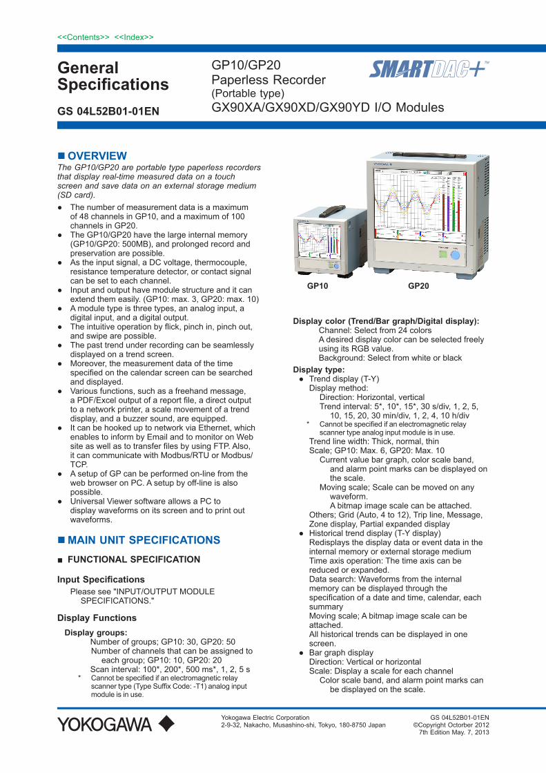
OVERVIEWThe GP10/GP20 are portable type paperless recorders that display real-time measured data on a touch screen and save data on an external storage medium (SD card).● The number of measurement data is a maximum
of 48 channels in GP10, and a maximum of 100 channels in GP20.
● The GP10/GP20 have the large internal memory (GP10/GP20: 500MB), and prolonged record and preservation are possible.
● As the input signal, a DC voltage, thermocouple, resistance temperature detector, or contact signal can be set to each channel.
● Input and output have module structure and it can extend them easily. (GP10: max. 3, GP20: max. 10)
● A module type is three types, an analog input, a digital input, and a digital output.
● The intuitive operation by flick, pinch in, pinch out, and swipe are possible.
● The past trend under recording can be seamlessly displayed on a trend screen.
● Moreover, the measurement data of the time specified on the calendar screen can be searched and displayed.
● Various functions, such as a freehand message, a PDF/Excel output of a report file, a direct output to a network printer, a scale movement of a trend display, and a buzzer sound, are equipped.
● It can be hooked up to network via Ethernet, which enables to inform by Email and to monitor on Web site as well as to transfer files by using FTP. Also, it can communicate with Modbus/RTU or Modbus/TCP.
● A setup of GP can be performed on-line from the web browser on PC. A setup by off-line is also possible.
● Universal Viewer software allows a PC to display waveforms on its screen and to print out waveforms.
MAIN UNIT SPECIFICATIONS■ FUNCTIONAL SPECIFICATION
Input SpecificationsPlease see "INPUT/OUTPUT MODULE
SPECIFICATIONS."
Display FunctionsDisplay groups:
Number of groups; GP10: 30, GP20: 50Number of channels that can be assigned to
each group; GP10: 10, GP20: 20 Scan interval: 100*, 200*, 500 ms*, 1, 2, 5 s
* Cannot be specified if an electromagnetic relay scanner type (Type Suffix Code: -T1) analog input module is in use.
Display color (Trend/Bar graph/Digital display): Channel: Select from 24 colors A desired display color can be selected freely
using its RGB value. Background: Select from white or black
Display type:● Trend display (T-Y) Display method:
Direction: Horizontal, verticalTrend interval: 5*, 10*, 15*, 30 s/div, 1, 2, 5,
10, 15, 20, 30 min/div, 1, 2, 4, 10 h/div* Cannot be specified if an electromagnetic relay
scanner type analog input module is in use. Trend line width: Thick, normal, thin Scale; GP10: Max. 6, GP20: Max. 10
Current value bar graph, color scale band, and alarm point marks can be displayed on the scale.
Moving scale; Scale can be moved on any waveform. A bitmap image scale can be attached.
Others; Grid (Auto, 4 to 12), Trip line, Message, Zone display, Partial expanded display
● Historical trend display (T-Y display) Redisplays the display data or event data in the
internal memory or external storage medium Time axis operation: The time axis can be
reduced or expanded. Data search: Waveforms from the internal
memory can be displayed through the specification of a date and time, calendar, each summary
Moving scale; A bitmap image scale can be attached.
All historical trends can be displayed in one screen.
● Bar graph display Direction: Vertical or horizontal Scale: Display a scale for each channel
Color scale band, and alarm point marks can be displayed on the scale.
GP10 GP20
2
All Rights Reserved. Copyright © 2012-2013, Yokogawa Electric Corporation
<<Contents>> <<Index>>
GS 04L52B01-01EN May. 7, 2013-00
● Digital display Displays measured values numerically A DI input state can be displayed as an arbitrary
character string (0=Off/1=On, etc.) Update rate: 0.5 s● Overview display Display format: All channels (GP10: Max. 30,
GP20: Max. 100), each groups Displays the measured values of all channels
and the alarm statuses● Alarm summary display Displays a log of up to 1000 alarms Specify an alarm with the cursor and jump to
the corresponding section on the historical trend display.
● Message summary display Time and content of up to 500 messages
(including 50 add messages) Specify a message with the cursor and jump to
the corresponding section on the historical trend display.
● Memory summary display Displays the information (up to 500) of the data
in the memory Specify a file with the cursor and jump to the
corresponding section on the historical trend display.
● Report display Displays the report data residing in the internal
memory For more details, see "MATHEMATICAL
FUNCTIONS WITH REPORT FUNCTION (/MT)."● Log display Displays the event log, error log, communication
log, FTP log, Web log, e-mail log, SNTP log, DHCP log, and Modbus log.
● Multi-panel display Divides the screen into two to six sections and
displays some different display formats.● Other displays Network information display System information display System configuration display
Auto scroll: The displayed groups can be automatically
switched at a specified interval. The display switches in ascending group order.
Names of channels:
Channel number; Analog input: 01 to 10 Digital input: 01 to 16 Digital output: 01 to 06
X X X X
Slot number; GP10: 0 to 2, GP20: 0 to 9Main unit: 0
Tags:• Tag and Tag numbers can be displayed.• Tag number; Number of characters: Up to 16 Displayable characters: Alphanumeric characters Tag numbers can be enabled or disabled.• Tag; Number of characters: Up to 32 Displayable characters: Alphanumeric characters
Message:• Write messages to the trend display.• Number of messages: 100• Number of characters: Up to 32• Write method: Write a preset message or write
an arbitrary message on the spot.• Write destination: Select only the displayed
group or all groups.• Auto message: Write a message when the GP
recovers from a power failure while memory sampling is in progress.
Write a message when the trend interval is switched during memory sampling.
Add message:• Write messages to the past data positions.• Message: The same as the “Message” item
above Number of writable messages per file: 50
messages (including 10 freehand messages)Freehand message:
• Can be written by dedicated pen. Number of writable messages per file: 50
messages (including 10 Add messages)
Data Saving FunctionsInternal memory:
• Temporarily saves various types of data.• Medium: Flash memory• File storage capacity; 500 MB
External storage medium:• Medium SD card (SD/SDHC) (up to 32 GB)• Format: FAT32 or FAT16
Data type:• Display data, Event data, Alarm summary data,
Manual sampled data, Screen image data, Setup data, and Report data
Display data:• Target: Measurement (input/output module)/
math/communication channels, alarm summary, message summary
Description: Maximum or minimum value per recordling interval
• Recording intervals: Determined by the trend interval
For GP20
Trend interval (div) Number of channels5 s 100
10 s 200
15 s or longer 500
Note that the maximum number of channels is fixed at 100 in the GP10.
• Data size; Analog input data: 12 bytes/ch. Digital I/O data: 4 bytes/ch. Math channel data: 12 bytes/ch. Communication channel data: 12 bytes/ch.
• File size: Up to 18 MB• Number of files: Up to 500 (including event data)• Operation in the internal memory: FIFO (First In
First Out)• Data format: Binary or text• Recording: Records data at all times.

3<<Contents>> <<Index>>
All Rights Reserved. Copyright © 2012-2013, Yokogawa Electric Corporation GS 04L52B01-01EN May. 7, 2013-00
• Display data file sample time Measurement channel = 30. Math Channel = 0
Internal Memory 500 MB
Trend interval (minute/div) 30 minutes
Recording interval (s) 60 s
Total sample time Approx. 2.5 years
Event data:• Target: Measurement (input/output module)/
math/communication channels, alarm summary, message summary, operation log
Description: Instantaneous value per recording interval
• Recording intervals: Determined by the sample rate
For GP20
Sampling rate Number of channels100 ms 100
200 ms 200
500 ms or longer 500
Note that the maximum number of channels is fixed at 100 in the GP10.
• Data size; Analog input data: 6 bytes/ch. Digital I/O data: 2 bytes/ch. Math channel data: 6 bytes/ch. Communication channel data: 6 bytes/ch.
• File size: Up to 18 MB• Number of files: Up to 500 (including display
data)• Operation in the internal memory: FIFO (First In
First Out)• Data format: Binary or text• Mode; Free: Records data at all times.
Trigger: Starts recording data when a certain event occurs and records for the specified interval.
Repetition trigger: Repeat Trigger mode• Event data file sample time Measurement channel = 30. Math Channel = 0
Internal Memory 500 MB
Recording period (s) 1 s
Total sample time Approx. 1 month
Alarm Functions• Number of alarms: Up to four alarms (level) for
each measurement channels• Alarm type: High limit, low limit, difference high
limit, difference low limit, high limit on rate-of-change alarm, low limit on rate-of-change alarm, delay high limit, and delay low limit
• Alarm delay time: 1 s to 24 hours (for each channel)
• Rate-of-change calculation interval of rate-of-change alarms: 1 to 32 times the scan interval (common to all channels)
• Hysteresis: 0.0 to 5.0% of the span (for each alarm (level))
• Alarm output: Output to the internal switch Internal switch operation: AND/OR operation
selectable
• Display: Displays the status on the respective operation screen and an alarm icon on the status display section when an alarm occurs.
Display operation: Hold or not hold the display until the alarm acknowledge operation
• Alarm hide function (alarm no logging function) Not display alarms nor record to the alarm
summary (for each channel)• Alarm information: Displays a log of alarm
occurrences on the alarm summary• Reflash: The duration for which the reflash relays
are deactivated can be set to 500 ms, 1 s, or 2 s.
Event Action Functions• Event action: Execute a specified operation
when a given event occurs.• Number of settings: 50 Events: Remote control input, etc. Timer; Number of timers: 4 Match time timer; Number of timers: 4 Action: Specify memory start/stop, alarm ACK,
etc.
Security Functions• Operation lock function: Limitations to touch
operation, access to the external storage medium, and various operations
• Login function: Only registered users can operate the GP.
It can be set to each of touch operation and communication access.
System administrators and Users: 50 (totally) Number of Authority of user: 10 level
Manual Sampled Data• Item: Instantaneous value at an arbitrary time• Target: Measurement (input/output module)/
math/communication channels• Number of recording channels: Max. 50• Maximum number of data values that the internal
memory can store: 400• Data format: Text
Report Data• Item: Report at each scheduled time of report• Target: Measurement (input/output module)/
math/communication channels• Maximum number of reports that the internal
memory can store: 800• Data format: Text
Snapshot Data• Item: Displayed screen image data• Data format: PNG• Output destination: External medium or
communication output
Setup Data• Item: GP setup data• Data format: text• Output/read destination (for saving/loading):
External medium
4
All Rights Reserved. Copyright © 2012-2013, Yokogawa Electric Corporation
<<Contents>> <<Index>>
GS 04L52B01-01EN May. 7, 2013-00
Clock Functions• Clock: With a calendar function• Accuracy: ± 5 ppm (0 to 50°C), excluding a delay
(of 1 second, maximum) caused each time the power is turned on.
• Time setting: Using touch operation, communication command, event action function, or SNTP client function
• Time adjustment method: Limit in which the time is gradually adjusted:
Select from the available settings between 5 s and 15 s.
Whether to change an out-of-limit operation immediately or report it as an error can be selected.
While memory sampling: Corrects the time by 1 ms for each second.
While memory is stopped: Immediately change the time.
• DST: The date/time for switching between standard time and DST can be specified.
• Time zone: Sets the time difference from GMT.• Date format: Select "YYYY/MM/DD", "MM/DD/
YYYY", "DD/MM/YYYY" or "DD.MM.YYYY". MM expression can be selected from the numeric character or ellipsis. Ex. January: 01 or Jan The delimiter can be selected from "/", ".", "-".
Ethernet Communication Functions• Electrical specifications: Conforms to IEEE 802.3• Connection: Ethernet (10BASE-T/100BASE-TX)• Max. segment length: 100 m• Max. connecting configuration: Cascade Max. 4
level (10BASE-T), Max. 2 level (100BASE-TX)• Connector: RJ-45• Protocols: TCP, UDP, IP, ICMP, ARP, DHCP,
HTTP, FTP, SMTP, SNTP, Modbus, and dedicated protocols
• E-mail client: Automatically send e-mail at specified times.
E-mail is sent by events as below.- Alarm occurring/alarm canceling- Recover from power failure- Report data generating- Storage medium error, FTP client function
error- Specified time period
POP before SMTP and SMTP authentication (PLAIN and CRAM-MD5) is available.
• FTP client: Automatically transfer data files to the FTP server.
Applicable files: Display data, event data, screen image data, report data, etc.
• FTP Server: Transfer files, delete files, manipulate directories, and output file lists of the GP.
• Web server: GP real-time monitoring and setting changes/operations can be performed with the Web browser.
• SNTP client: Inquires the time to the SNTP server and sets the GP.
• SNTP server: Outputs the GP time. Time resolution: 5 ms• DHCP client: Automatically obtain the network
address settings from the DHCP server.
• Modbus client: Reads data from another device and writes to the registers.
• Modbus server: Loads measurement and math channel data
Loads and writes communication channel data Some control commands such as memory start Modbus client* register access limitations
*: Required /MC option• Setting/Measurement server: Operate, set, and
output data of the GP using a dedicated protocol.
Batch Function• Function: Data management using batch names.
Enter text fields and batch comments in the data file.
• Batch name: Added to the file name of the display data and event data.
Structure: Batch number (up to 32 characters) + lot number (up to 8 digits)
Use/not use selectable for lot number, on/off selectable for auto increment function.
• Text field: Adds text to the display data and event data.
There are 24 available text fields. Up to 20 title characters and 30 other characters
can be entered per field.• Batch comment: Adds text to the display data
and event data. 3 comments (max. 50 characters) are available.
Printer Output Function• Snapshot Data can be printed out with any
LAN-connected printer supporting the HP-PCL5 language.
Other Functions• Buzzer: GP makes a buzzer sound at touch
screen operation, or when alarm occurs.• Backlight saver function: Dim or turn off the
LCD backlight if there is no key operation for a specified time.
• Favorite display: Register frequently used displays to the Favorite and show them through simple operation.
• The main alarm is indicated using the MENU key LED.
No alarm: Blue (same condition as power-on) Alarm condition: Red.
5<<Contents>> <<Index>>
All Rights Reserved. Copyright © 2012-2013, Yokogawa Electric Corporation GS 04L52B01-01EN May. 7, 2013-00
HARDWARE SPECIFICATIONS (MAIN UNIT)
DisplayDisplay unit*:
GP10: 5.7-inch TFT color LCD (640 × 480 dots)GP20: 12.1-inch TFT color LCD (800 × 600 dots)* A small number of missing or steady-on LCD
pixels and minor variations in brightness uniformity is a normal display characteristic and not a malfunction.
Touch screen:4 wire resistive touch screen
Construction• Material;
Case: Metal plate Bezel and display cover: Polycarbonate
• Color; Case: Smoke blue Bezel: Charcoal grey light
• External dimensions: When installing modules GP10: 144(W) × 168(H) × 248(D) mm
GP20: 288(W) × 318(H) × 248(D) mm When uninstalling modules
GP10: 144(W) × 168(H) × 197(D) mm GP20: 288(W) × 318(H) × 197(D) mm (D: depth from the panel mounting plane)• Weight:
GP10: Approx. 1.9 kg, GP20: Approx. 5.7 kg (excluding modules)
Power Supply• Rated supply voltage: 100 to 240 VAC• Allowable power supply voltage range: 90 to 132,
180 to 264 VAC• Rated power supply frequency: 50/60 Hz• Power consumption:
Supply voltage
LCD backlight off
Normal operation
Maximum
100 V AC GP10: 16 VAGP20: 28 VA
GP10: 20 VAGP20: 34 VA
GP10: 48 VAGP20: 90 VA
240 V AC GP10: 24 VAGP20: 38 VA
GP10: 30 VAGP20: 45 VA
GP10: 60 VAGP20: 110 VA
* The following combinations are assumed for LCD backlight off and normal operation.
GP10: 1 AI module, 1 DO module, 1 DI moduleGP20: 5 AI modules, 4 DO modules, 1 DI module
• Module power supply voltage: The total allowable power consumption of respective modules is up to 6 W in the GP10 and up to 20 W in the GP20.
• Allowable interruption time: Less than 1 cycle of the power supply frequency
Isolation• Insulation resistance: Between the Ethernet,
RS-422/485, and each insulation terminals and earth: 20 MΩ or greater at 500 VDC
• Withstand voltage: Between the power terminal and earth: 3000 V AC at 50/60 Hz for one minute
Between the contact output terminal and earth: 3000 VAC at 50/60 Hz for one minute
Between the input/output modules and earth: Depends on the specification of I/O module.
• Ground; Grounding resistance: 100 Ω or less• Isolation:
Power terminal
The circuits divided by lines are insulated mutually.
Internal circuit
FAIL output terminalEthernet portRS-422/485 terminalInput and output module terminal
Input and output module internal circuitEarth (PE) terminalRS-232 terminalSD card slotUSB port
Safety and EMC Standards• CSA: CSA22.2 No.61010.1, installation
category II (*1), and pollution degree 2 (*2), and CSA-C22.2 NO. 61010-2-030-12
• UL: UL61010-1, UL 61010-2-030 (CSA NRTL/C)• CE: EMC directive EN61326-1 compliance, Class A Table 2 EN61000-3-2 compliance EN61000-3-3 compliance EN55011 Class A Group 1 Low voltage directive EN61010-1, EN 61010-2-030 Installation category II (*1) Pollution degree 2 (*2) Measurement category II (*3)• C-Tick: EN55011 compliance, Class A Group 1• KC marking: Electromagnetic wave interference
prevention standard, electromagnetic wave protection standard compliance
*1 Installation category (overvoltage category) II: Describes a number which defines a transient
overvoltage condition. Implies the regulation for impulse withstand
voltage. “II” applies to electrical equipment which
is supplied from the fixed installation like a distribution board.
*2 Pollution degree 2: Describes the degree to which a solid, liquid,
or gas which deteriorates dielectric strength or surface resistivity is adhering.
“2” applies to normal indoor atmosphere. Normally, only non-conductive pollution occurs.
*3 Measurement category: Depends on the specification of each modules
6
All Rights Reserved. Copyright © 2012-2013, Yokogawa Electric Corporation
<<Contents>> <<Index>>
GS 04L52B01-01EN May. 7, 2013-00
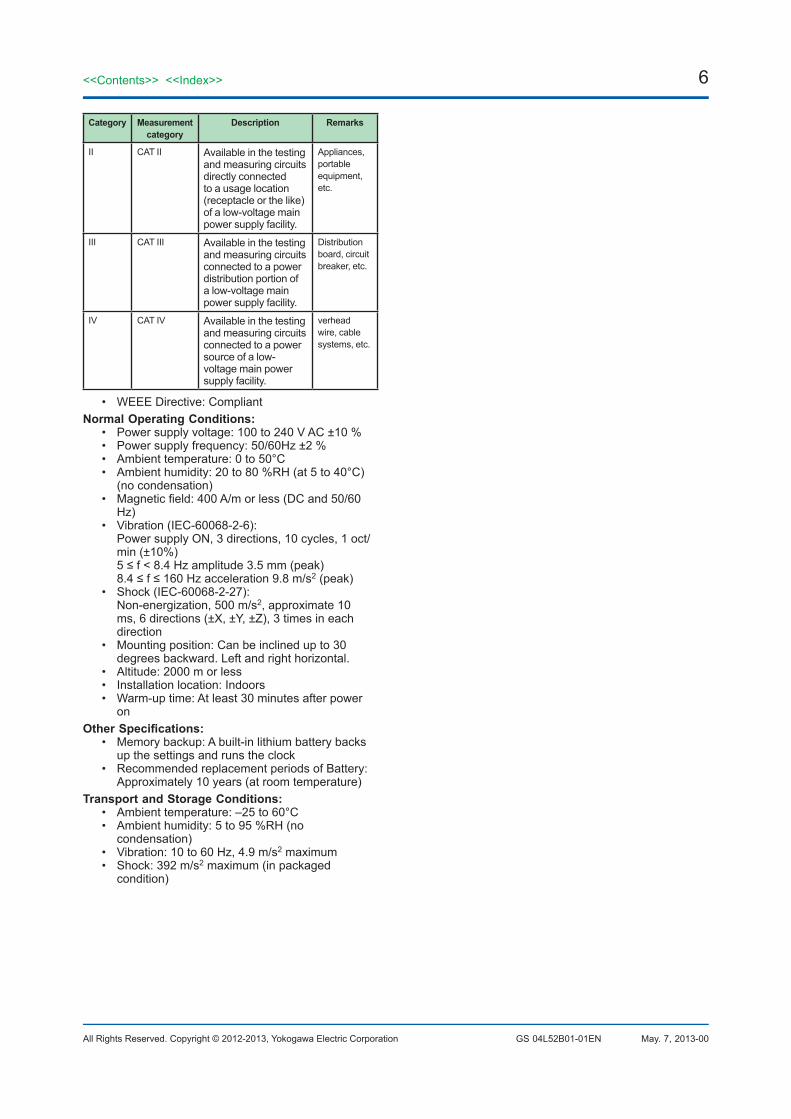
Category Measurement category
Description Remarks
II CAT II Available in the testing and measuring circuits directly connected to a usage location (receptacle or the like) of a low-voltage main power supply facility.
Appliances, portable equipment, etc.
III CAT III Available in the testing and measuring circuits connected to a power distribution portion of a low-voltage main power supply facility.
Distribution board, circuit breaker, etc.
IV CAT IV Available in the testing and measuring circuits connected to a power source of a low-voltage main power supply facility.
verhead wire, cable systems, etc.
• WEEE Directive: CompliantNormal Operating Conditions:
• Power supply voltage: 100 to 240 V AC ±10 %• Power supply frequency: 50/60Hz ±2 %• Ambient temperature: 0 to 50°C• Ambient humidity: 20 to 80 %RH (at 5 to 40°C)
(no condensation)• Magnetic field: 400 A/m or less (DC and 50/60
Hz)• Vibration (IEC-60068-2-6):
Power supply ON, 3 directions, 10 cycles, 1 oct/min (±10%)
5 ≤ f < 8.4 Hz amplitude 3.5 mm (peak) 8.4 ≤ f ≤ 160 Hz acceleration 9.8 m/s2 (peak)• Shock (IEC-60068-2-27):
Non-energization, 500 m/s2, approximate 10 ms, 6 directions (±X, ±Y, ±Z), 3 times in each direction
• Mounting position: Can be inclined up to 30 degrees backward. Left and right horizontal.
• Altitude: 2000 m or less• Installation location: Indoors• Warm-up time: At least 30 minutes after power
onOther Specifications:
• Memory backup: A built-in lithium battery backs up the settings and runs the clock
• Recommended replacement periods of Battery: Approximately 10 years (at room temperature)
Transport and Storage Conditions:• Ambient temperature: –25 to 60°C• Ambient humidity: 5 to 95 %RH (no
condensation)• Vibration: 10 to 60 Hz, 4.9 m/s2 maximum• Shock: 392 m/s2 maximum (in packaged
condition)
7<<Contents>> <<Index>>
All Rights Reserved. Copyright © 2012-2013, Yokogawa Electric Corporation GS 04L52B01-01EN May. 7, 2013-00
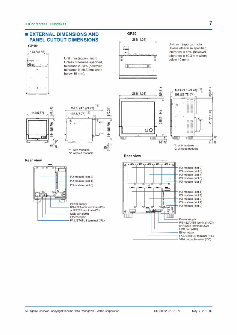
EXTERNAL DIMENSIONS AND PANEL CUTOUT DIMENSIONS
GP10:
*1: with modules*2: without moduels
Unit: mm (approx. inch)Unless otherwise specified, tolerance is ±3% (however, tolerance is ±0.3 mm when below 10 mm).
(*1)
(*2)MAX
8(0.
31)
8(0.
31)
144.
9(5.
70)
(0.5
9)15
196.8(7.75)
247.2(9.73)144(5.67)
144.
9(5.
70)
15 (0.5
9)143.6(5.65)
Rear view
Power supply
I/O module (slot 1)
RS-422A/485 terminal (/C3)or RS232 terminal (/C2)USB port (/UH)Ethernet portFAIL/STATUS terminal (/FL)
I/O module (slot 2)
I/O module (slot 0)
GP20:
Unit: mm (approx. inch)Unless otherwise specified, tolerance is ±3% (however, tolerance is ±0.3 mm when below 10 mm).
*1: with modules*2: without moduels
(*1)
(*2)MAX
288(11.34)
196.8(7.75)
287(
11.3
0)8(
0.31
)23 (0
.91)
247.2(9.73)
288(
11.3
4)
288(11.34) 8(0.
31)
22 (0.8
7)
Rear view
Power supplyRS-422A/485 terminal (/C3)or RS232 terminal (/C2)USB port (/UH)Ethernet portFAIL/STATUS terminal (/FL)VGA output terminal (/D5)
I/O module (slot 0)I/O module (slot 1)I/O module (slot 2)I/O module (slot 3)I/O module (slot 4)
I/O module (slot 5)I/O module (slot 6)I/O module (slot 7)I/O module (slot 8)I/O module (slot 9)
8
All Rights Reserved. Copyright © 2012-2013, Yokogawa Electric Corporation
<<Contents>> <<Index>>
GS 04L52B01-01EN May. 7, 2013-00
SPECIFICATIONS OF OPTIONAL FUNCTIONS
SERIAL COMMUNICATION INTERFACE (/C2, /C3)• Connection: EIA RS-232(/C2) or EIA RS-
422/485(/C3)• Protocol: Dedicated protocol or Modbus protocol• Setting/measurement server function: Operation,
setting or output of measurement data are available by dedicated protocol.
• Synchronization: Start-stop synchronization• Transmission mode (RS-422/485):
RS-422: Four-wire half-duplex multi-drop connection (1:n (n = 1 to 31)) RS485: Two-wire half-duplex multi-drop connection (1:n (n = 1 to 31))
• Baud rate: 1200, 2400, 4800, 9600, 19200, 38400, 57600, or 115200 bps
• Data length 7 or 8 bits• Start bit: 1 bit• Stop bit: 1 bit or 2 bit• Parity: ODD, EVEN, or NONE• Handshaking Off: Off, XON: XON, XON: RS, and
CS: RS• Communication distance; RS-422/485: 1200 m,
RS-232: 15 m• Modbus/RTU communication: Reading or writing
of measurement data on other instruments is available by Modbus protocol.
Math channel option is needed to read measurement data from other instruments.
• Operation modes: Master or slave
VGA VIDEO OUTPUT (/D5) (Only for GP20)• External display: Resolution: 800 × 600 dots (VGA) Connector: 15-pin D-Sub
FAIL OUTPUT (/FL)• Contact: C contact, 1 point• FAIL output: The relay contact output on the rear panel
indicates the occurrence of CPU failure. Relay operation: Energized during normal
operation and de-energized on CPU failure.• Rated power supply voltage: 24 V DC or 250 V
AC or less• Rated load current: 3A (DC)/3A (AC), resistance
load• Min. load current: 100 mA• Recommended replacement periods of contact: Electrical: 30,000 more ON-OFF operations,
Mechanical: 5,000,000 more ON-OFF operations
MATHEMATICAL FUNCTIONS WITH REPORT FUNCTION (/MT)
Mathematical Function:• Number of math channels; GP10: 50, GP20: 100• Operation: General arithmetic operations: Four arithmetic
operations (+, -, *, /), square root, absolute, common logarithm, natural logarithm, exponential, and power
Relational operations: <, ≤, >, ≥, =, and ≠ Logic operations: AND, OR, NOT, and XOR Statistical operations: TLOG or CLOG Special operations: PRE, HOLD, RESET, and
CARRY Conditional operation: [a?b:c]• Computation accuracy: Double-precision floating
point• Data that can be used; Channel data: Measurement channels
(GP10: 0001 to 0216, GP20: 0001 to 0916), mathematical channels (GP10: A001 to A050, GP20: A001 to A100), Communication channels (GP10: C001 to C050, GP20: C001 to C300)
Constants: 100 (K001 to K100), Internal switch: 100 (S001 to S100), Flag: 20 (F01 to F20)
Report function:• Number of report channels; GP10: 50, GP20: 60• Report types: Hourly + daily, daily + weekly, daily
+ monthly, Batch, Day custom• Computation types: Average, maximum,
minimum, sum, or instantaneous value• Unit of sum: OFF, /s, /min, /hour, /day• Report templates: Office Open XML spreadsheet
files (which can be displayed with Microsoft Office Excel) or PDF files can be output or printed out with any LAN-connected printer supporting the HP-PCL5 language.
COMMUNICATION CHANNEL FUNCTIONS (/MC)• Number of communication channels; GP10: 50
(C0001 to C050), GP20: 300 (C001 to C300)* Required to record data from Modbus devices or
PCs on the GP.
9<<Contents>> <<Index>>
All Rights Reserved. Copyright © 2012-2013, Yokogawa Electric Corporation GS 04L52B01-01EN May. 7, 2013-00
USB INTERFACE (/UH)• USB port: Complies with USB 2.0 and host
function• Number of ports: 2 (one each on the front panel
and rear panel)• Connectable devices: Only connect the devices
listed below to prevent damage to the devices.Keyboard: Complies with HID Class Ver. 1.1 104/89 keyboard (US) and 109/89
keyboard (Japanese)Mouse: Complies with HID Class Ver. 1.1External medium: USB flash memory Does not guarantee the operation of all
USB flash memories External medium such as a hard disk, ZIP,
MO, and optical discs are not supported.Barcode reader: USB HID Class Ver. 1.1
compatible English (U.S.) standard USB keyboard
compatible• Power supply: 5 V ±10%, 500 mA *1
*1: Devices which need more than 500 mA total bus power for 2 ports cannot be connected at the same time.
For low powered devices (bus power < 100 mA): 5V ± 5%
For high powered devices (bus power < 500 mA): 5V ± 10%
10
All Rights Reserved. Copyright © 2012-2013, Yokogawa Electric Corporation
<<Contents>> <<Index>>
GS 04L52B01-01EN May. 7, 2013-00
INPUT/OUTPUT MODULE SPECIFICATIONS
GX90XA
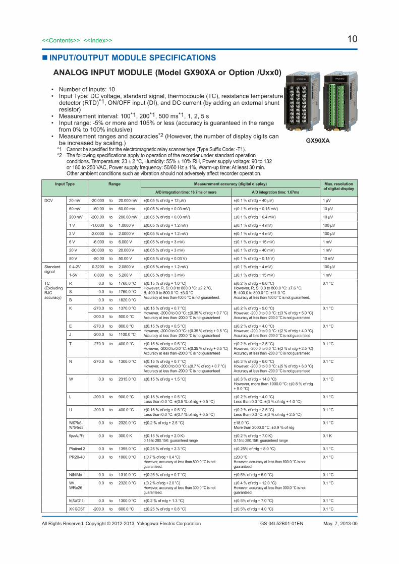
ANALOG INPUT MODULE (Model GX90XA or Option /Uxx0)
• Number of inputs: 10• Input Type: DC voltage, standard signal, thermocouple (TC), resistance temperature
detector (RTD)*1, ON/OFF input (DI), and DC current (by adding an external shunt resistor)
• Measurement interval: 100*1, 200*1, 500 ms*1, 1, 2, 5 s• Input range: -5% or more and 105% or less (accuracy is guaranteed in the range
from 0% to 100% inclusive)• Measurement ranges and accuracies*2 (However, the number of display digits can
be increased by scaling.)*1 Cannot be specified for the electromagnetic relay scanner type (Type Suffix Code: -T1).*2 The following specifications apply to operation of the recorder under standard operation
conditions. Temperature: 23 ± 2 °C, Humidity: 55% ± 10% RH, Power supply voltage: 90 to 132 or 180 to 250 VAC, Power supply frequency: 50/60 Hz ± 1%, Warm-up time: At least 30 min. Other ambient conditions such as vibration should not adversely affect recorder operation.
Input Type Range Measurement accuracy (digital display) Max. resolution of digital display
A/D integration time: 16.7ms or more A/D integration time: 1.67ms
DCV 20 mV -20.000 to 20.000 mV ±(0.05 % of rdg + 12 μV) ±(0.1 % of rdg + 40 μV) 1 μV
60 mV -60.00 to 60.00 mV ±(0.05 % of rdg + 0.03 mV) ±(0.1 % of rdg + 0.15 mV) 10 μV
200 mV -200.00 to 200.00 mV ±(0.05 % of rdg + 0.03 mV) ±(0.1 % of rdg + 0.4 mV) 10 μV
1 V -1.0000 to 1.0000 V ±(0.05 % of rdg + 1.2 mV) ±(0.1 % of rdg + 4 mV) 100 μV
2 V -2.0000 to 2.0000 V ±(0.05 % of rdg + 1.2 mV) ±(0.1 % of rdg + 4 mV) 100 μV
6 V -6.000 to 6.000 V ±(0.05 % of rdg + 3 mV) ±(0.1 % of rdg + 15 mV) 1 mV
20 V -20.000 to 20.000 V ±(0.05 % of rdg + 3 mV) ±(0.1 % of rdg + 40 mV) 1 mV
50 V -50.00 to 50.00 V ±(0.05 % of rdg + 0.03 V) ±(0.1 % of rdg + 0.15 V) 10 mV
Standard signal
0.4-2V 0.3200 to 2.0800 V ±(0.05 % of rdg + 1.2 mV) ±(0.1 % of rdg + 4 mV) 100 μV
1-5V 0.800 to 5.200 V ±(0.05 % of rdg + 3 mV) ±(0.1 % of rdg + 15 mV) 1 mV
TC(Excluding RJC accuracy)
R 0.0 to 1760.0 °C ±(0.15 % of rdg + 1.0 °C)However, R, S; 0.0 to 800.0 °C: ±2.2 °C, B; 400.0 to 800.0 °C: ±3.0 °CAccuracy at less than 400.0 °C is not guaranteed.
±(0.2 % of rdg + 6.0 °C)However, R, S; 0.0 to 800.0 °C: ±7.6 °C, B; 400.0 to 800.0 °C: ±11.0 °CAccuracy at less than 400.0 °C is not guaranteed.
0.1 °C
S 0.0 to 1760.0 °C
B 0.0 to 1820.0 °C
K -270.0 to 1370.0 °C ±(0.15 % of rdg + 0.7 °C)However, -200.0 to 0.0 °C: ±(0.35 % of rdg + 0.7 °C)Accuracy at less than -200.0 °C is not guaranteed
±(0.2 % of rdg + 5.0 °C)However, -200.0 to 0.0 °C: ±(3 % of rdg + 5.0 °C)Accuracy at less than -200.0 °C is not guaranteed
0.1 °C
-200.0 to 500.0 °C
E -270.0 to 800.0 °C ±(0.15 % of rdg + 0.5 °C)However, -200.0 to 0.0 °C: ±(0.35 % of rdg + 0.5 °C)Accuracy at less than -200.0 °C is not guaranteed
±(0.2 % of rdg + 4.0 °C)However, -200.0 to 0.0 °C: ±(2 % of rdg + 4.0 °C)Accuracy at less than -200.0 °C is not guaranteed
0.1 °C
J -200.0 to 1100.0 °C
T -270.0 to 400.0 °C ±(0.15 % of rdg + 0.5 °C)However, -200.0 to 0.0 °C: ±(0.35 % of rdg + 0.5 °C)Accuracy at less than -200.0 °C is not guaranteed
±(0.2 % of rdg + 2.5 °C)However, -200.0 to 0.0 °C: ±(2 % of rdg + 2.5 °C)Accuracy at less than -200.0 °C is not guaranteed
0.1 °C
N -270.0 to 1300.0 °C ±(0.15 % of rdg + 0.7 °C)However, -200.0 to 0.0 °C: ±(0.7 % of rdg + 0.7 °C)Accuracy at less than -200.0 °C is not guaranteed
±(0.3 % of rdg + 6.0 °C)However, -200.0 to 0.0 °C: ±(5 % of rdg + 6.0 °C)Accuracy at less than -200.0 °C is not guaranteed
0.1 °C
W 0.0 to 2315.0 °C ±(0.15 % of rdg + 1.5 °C) ±(0.3 % of rdg + 14.0 °C)However, more than 1000.0 °C: ±(0.8 % of rdg + 9.0 °C)
0.1 °C
L -200.0 to 900.0 °C ±(0.15 % of rdg + 0.5 °C)Less than 0.0 °C: ±(0.5 % of rdg + 0.5 °C)
±(0.2 % of rdg + 4.0 °C)Less than 0.0 °C: ±(3 % of rdg + 4.0 °C)
0.1 °C
U -200.0 to 400.0 °C ±(0.15 % of rdg + 0.5 °C)Less than 0.0 °C: ±(0.7 % of rdg + 0.5 °C)
±(0.2 % of rdg + 2.5 °C)Less than 0.0 °C: ±(3 % of rdg + 2.5 °C)
0.1 °C
W97Re3-W75Re25
0.0 to 2320.0 °C ±(0.2 % of rdg + 2.5 °C) ±18.0 °CMore than 2000.0 °C: ±0.9 % of rdg
0.1 °C
KpvsAu7Fe 0.0 to 300.0 K ±(0.15 % of rdg + 2.0 K)0.15 to 280.15K: guaranteed range
±(0.2 % of rdg + 7.0 K)0.15 to 280.15K: guaranteed range
0.1 K
Platinel 2 0.0 to 1395.0 °C ±(0.25 % of rdg + 2.3 °C) ±(0.25% of rdg + 8.0 °C) 0.1 °C
PR20-40 0.0 to 1900.0 °C ±(0.7 % of rdg + 0.4 °C)However, accuracy at less than 800.0 °C is not guaranteed.
±20.0 °CHowever, accuracy at less than 800.0 °C is not guaranteed.
0.1 °C
NiNiMo 0.0 to 1310.0 °C ±(0.25 % of rdg + 0.7 °C) ±(0.5% of rdg + 5.0 °C) 0.1 °C
W/WRe26
0.0 to 2320.0 °C ±(0.2 % of rdg + 2.0 °C)However, accuracy at less than 300.0 °C is not guaranteed.
±(0.4 % of rdg + 12.0 °C)However, accuracy at less than 300.0 °C is not guaranteed.
0.1 °C
N(AWG14) 0.0 to 1300.0 °C ±(0.2 % of rdg + 1.3 °C) ±(0.5% of rdg + 7.0 °C) 0.1 °C
XK GOST -200.0 to 600.0 °C ±(0.25 % of rdg + 0.8 °C) ±(0.5% of rdg + 4.0 °C) 0.1 °C
11<<Contents>> <<Index>>
All Rights Reserved. Copyright © 2012-2013, Yokogawa Electric Corporation GS 04L52B01-01EN May. 7, 2013-00
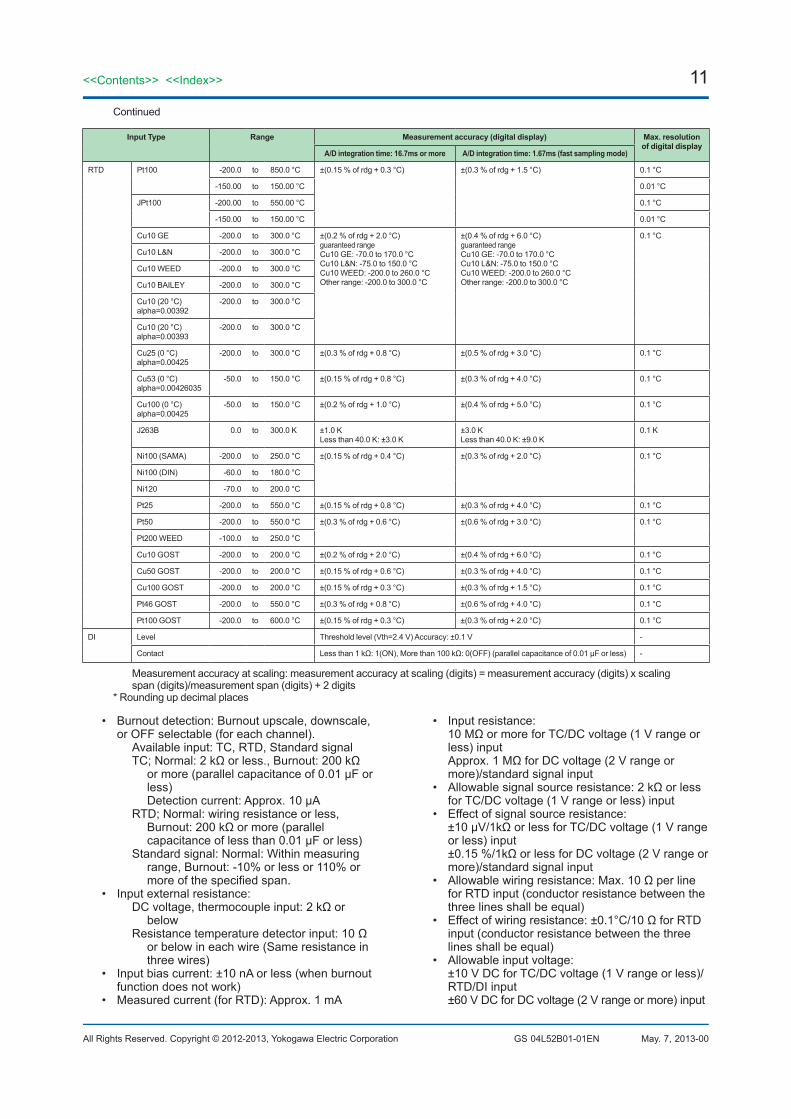
Continued
Input Type Range Measurement accuracy (digital display) Max. resolution of digital display
A/D integration time: 16.7ms or more A/D integration time: 1.67ms (fast sampling mode)
RTD Pt100 -200.0 to 850.0 °C ±(0.15 % of rdg + 0.3 °C) ±(0.3 % of rdg + 1.5 °C) 0.1 °C
-150.00 to 150.00 °C 0.01 °C
JPt100 -200.00 to 550.00 °C 0.1 °C
-150.00 to 150.00 °C 0.01 °C
Cu10 GE -200.0 to 300.0 °C ±(0.2 % of rdg + 2.0 °C)guaranteed rangeCu10 GE: -70.0 to 170.0 °CCu10 L&N: -75.0 to 150.0 °CCu10 WEED: -200.0 to 260.0 °COther range: -200.0 to 300.0 °C
±(0.4 % of rdg + 6.0 °C)guaranteed rangeCu10 GE: -70.0 to 170.0 °CCu10 L&N: -75.0 to 150.0 °CCu10 WEED: -200.0 to 260.0 °COther range: -200.0 to 300.0 °C
0.1 °C
Cu10 L&N -200.0 to 300.0 °C
Cu10 WEED -200.0 to 300.0 °C
Cu10 BAILEY -200.0 to 300.0 °C
Cu10 (20 °C)alpha=0.00392
-200.0 to 300.0 °C
Cu10 (20 °C)alpha=0.00393
-200.0 to 300.0 °C
Cu25 (0 °C)alpha=0.00425
-200.0 to 300.0 °C ±(0.3 % of rdg + 0.8 °C) ±(0.5 % of rdg + 3.0 °C) 0.1 °C
Cu53 (0 °C)alpha=0.00426035
-50.0 to 150.0 °C ±(0.15 % of rdg + 0.8 °C) ±(0.3 % of rdg + 4.0 °C) 0.1 °C
Cu100 (0 °C)alpha=0.00425
-50.0 to 150.0 °C ±(0.2 % of rdg + 1.0 °C) ±(0.4 % of rdg + 5.0 °C) 0.1 °C
J263B 0.0 to 300.0 K ±1.0 KLess than 40.0 K: ±3.0 K
±3.0 KLess than 40.0 K: ±9.0 K
0.1 K
Ni100 (SAMA) -200.0 to 250.0 °C ±(0.15 % of rdg + 0.4 °C) ±(0.3 % of rdg + 2.0 °C) 0.1 °C
Ni100 (DIN) -60.0 to 180.0 °C
Ni120 -70.0 to 200.0 °C
Pt25 -200.0 to 550.0 °C ±(0.15 % of rdg + 0.8 °C) ±(0.3 % of rdg + 4.0 °C) 0.1 °C
Pt50 -200.0 to 550.0 °C ±(0.3 % of rdg + 0.6 °C) ±(0.6 % of rdg + 3.0 °C) 0.1 °C
Pt200 WEED -100.0 to 250.0 °C
Cu10 GOST -200.0 to 200.0 °C ±(0.2 % of rdg + 2.0 °C) ±(0.4 % of rdg + 6.0 °C) 0.1 °C
Cu50 GOST -200.0 to 200.0 °C ±(0.15 % of rdg + 0.6 °C) ±(0.3 % of rdg + 4.0 °C) 0.1 °C
Cu100 GOST -200.0 to 200.0 °C ±(0.15 % of rdg + 0.3 °C) ±(0.3 % of rdg + 1.5 °C) 0.1 °C
Pt46 GOST -200.0 to 550.0 °C ±(0.3 % of rdg + 0.8 °C) ±(0.6 % of rdg + 4.0 °C) 0.1 °C
Pt100 GOST -200.0 to 600.0 °C ±(0.15 % of rdg + 0.3 °C) ±(0.3 % of rdg + 2.0 °C) 0.1 °C
DI Level Threshold level (Vth=2.4 V) Accuracy: ±0.1 V -
Contact Less than 1 kΩ: 1(ON), More than 100 kΩ: 0(OFF) (parallel capacitance of 0.01 μF or less) -
Measurement accuracy at scaling: measurement accuracy at scaling (digits) = measurement accuracy (digits) x scaling span (digits)/measurement span (digits) + 2 digits
* Rounding up decimal places
• Burnout detection: Burnout upscale, downscale, or OFF selectable (for each channel).
Available input: TC, RTD, Standard signalTC; Normal: 2 kΩ or less., Burnout: 200 kΩ
or more (parallel capacitance of 0.01 μF or less)
Detection current: Approx. 10 μARTD; Normal: wiring resistance or less,
Burnout: 200 kΩ or more (parallel capacitance of less than 0.01 μF or less)
Standard signal: Normal: Within measuring range, Burnout: -10% or less or 110% or more of the specified span.
• Input external resistance:DC voltage, thermocouple input: 2 kΩ or
belowResistance temperature detector input: 10 Ω
or below in each wire (Same resistance in three wires)
• Input bias current: ±10 nA or less (when burnout function does not work)
• Measured current (for RTD): Approx. 1 mA
• Input resistance: 10 MΩ or more for TC/DC voltage (1 V range or less) input Approx. 1 MΩ for DC voltage (2 V range or more)/standard signal input
• Allowable signal source resistance: 2 kΩ or less for TC/DC voltage (1 V range or less) input
• Effect of signal source resistance: ±10 μV/1kΩ or less for TC/DC voltage (1 V range or less) input ±0.15 %/1kΩ or less for DC voltage (2 V range or more)/standard signal input
• Allowable wiring resistance: Max. 10 Ω per line for RTD input (conductor resistance between the three lines shall be equal)
• Effect of wiring resistance: ±0.1°C/10 Ω for RTD input (conductor resistance between the three lines shall be equal)
• Allowable input voltage: ±10 V DC for TC/DC voltage (1 V range or less)/RTD/DI input ±60 V DC for DC voltage (2 V range or more) input
12
All Rights Reserved. Copyright © 2012-2013, Yokogawa Electric Corporation
<<Contents>> <<Index>>
GS 04L52B01-01EN May. 7, 2013-00
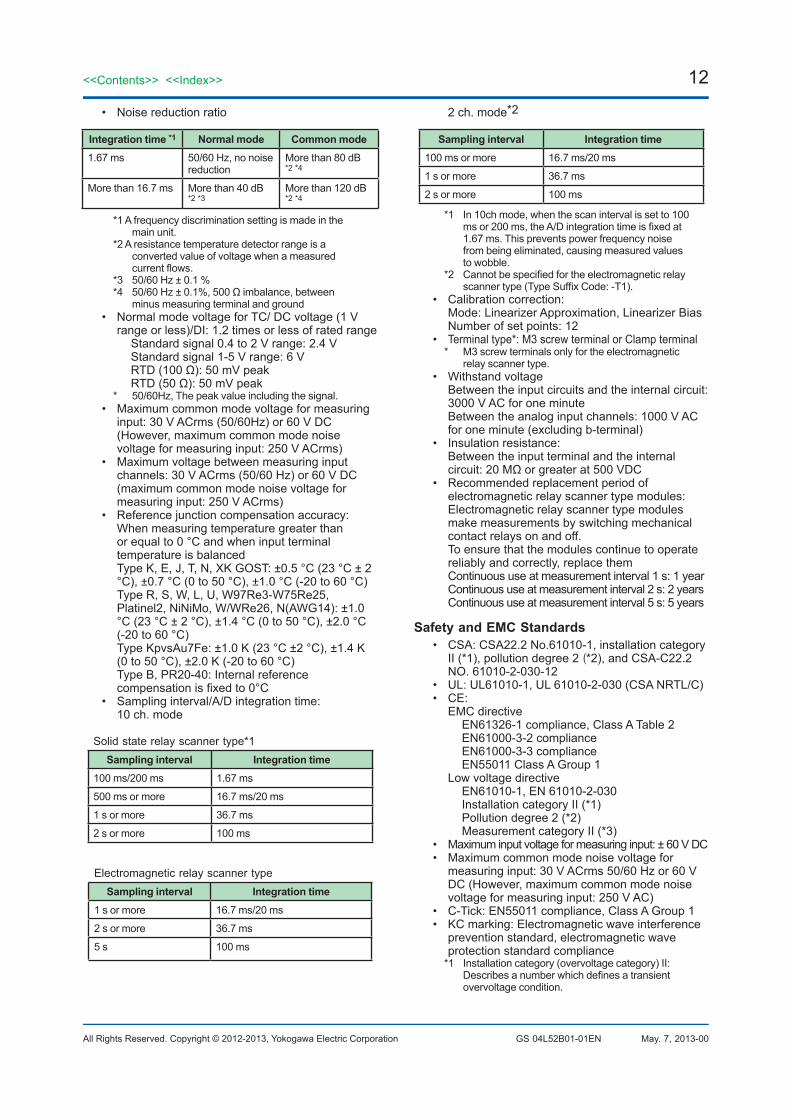
• Noise reduction ratio
Integration time *1 Normal mode Common mode1.67 ms 50/60 Hz, no noise
reductionMore than 80 dB *2 *4
More than 16.7 ms More than 40 dB *2 *3
More than 120 dB *2 *4
*1 A frequency discrimination setting is made in the main unit.
*2 A resistance temperature detector range is a converted value of voltage when a measured current flows.
*3 50/60 Hz ± 0.1 %*4 50/60 Hz ± 0.1%, 500 Ω imbalance, between
minus measuring terminal and ground• Normal mode voltage for TC/ DC voltage (1 V
range or less)/DI: 1.2 times or less of rated range Standard signal 0.4 to 2 V range: 2.4 V Standard signal 1-5 V range: 6 V RTD (100 Ω): 50 mV peak RTD (50 Ω): 50 mV peak
* 50/60Hz, The peak value including the signal.• Maximum common mode voltage for measuring
input: 30 V ACrms (50/60Hz) or 60 V DC (However, maximum common mode noise voltage for measuring input: 250 V ACrms)
• Maximum voltage between measuring input channels: 30 V ACrms (50/60 Hz) or 60 V DC (maximum common mode noise voltage for measuring input: 250 V ACrms)
• Reference junction compensation accuracy: When measuring temperature greater than
or equal to 0 °C and when input terminal temperature is balanced
Type K, E, J, T, N, XK GOST: ±0.5 °C (23 °C ± 2 °C), ±0.7 °C (0 to 50 °C), ±1.0 °C (-20 to 60 °C)
Type R, S, W, L, U, W97Re3-W75Re25, Platinel2, NiNiMo, W/WRe26, N(AWG14): ±1.0 °C (23 °C ± 2 °C), ±1.4 °C (0 to 50 °C), ±2.0 °C (-20 to 60 °C)
Type KpvsAu7Fe: ±1.0 K (23 °C ±2 °C), ±1.4 K (0 to 50 °C), ±2.0 K (-20 to 60 °C)
Type B, PR20-40: Internal reference compensation is fixed to 0°C
• Sampling interval/A/D integration time: 10 ch. mode
Solid state relay scanner type*1Sampling interval Integration time
100 ms/200 ms 1.67 ms
500 ms or more 16.7 ms/20 ms
1 s or more 36.7 ms
2 s or more 100 ms
Electromagnetic relay scanner typeSampling interval Integration time
1 s or more 16.7 ms/20 ms
2 s or more 36.7 ms
5 s 100 ms
2 ch. mode*2
Sampling interval Integration time100 ms or more 16.7 ms/20 ms
1 s or more 36.7 ms
2 s or more 100 ms
*1 In 10ch mode, when the scan interval is set to 100 ms or 200 ms, the A/D integration time is fixed at 1.67 ms. This prevents power frequency noise from being eliminated, causing measured values to wobble.
*2 Cannot be specified for the electromagnetic relay scanner type (Type Suffix Code: -T1).
• Calibration correction: Mode: Linearizer Approximation, Linearizer Bias Number of set points: 12
• Terminal type*: M3 screw terminal or Clamp terminal* M3 screw terminals only for the electromagnetic
relay scanner type.• Withstand voltage Between the input circuits and the internal circuit:
3000 V AC for one minute Between the analog input channels: 1000 V AC
for one minute (excluding b-terminal)• Insulation resistance:
Between the input terminal and the internal circuit: 20 MΩ or greater at 500 VDC
• Recommended replacement period of electromagnetic relay scanner type modules:
Electromagnetic relay scanner type modules make measurements by switching mechanical contact relays on and off.
To ensure that the modules continue to operate reliably and correctly, replace them
Continuous use at measurement interval 1 s: 1 year Continuous use at measurement interval 2 s: 2 years Continuous use at measurement interval 5 s: 5 years
Safety and EMC Standards• CSA: CSA22.2 No.61010-1, installation category
II (*1), pollution degree 2 (*2), and CSA-C22.2 NO. 61010-2-030-12
• UL: UL61010-1, UL 61010-2-030 (CSA NRTL/C)• CE: EMC directive EN61326-1 compliance, Class A Table 2 EN61000-3-2 compliance EN61000-3-3 compliance EN55011 Class A Group 1 Low voltage directive EN61010-1, EN 61010-2-030 Installation category II (*1) Pollution degree 2 (*2) Measurement category II (*3)• Maximum input voltage for measuring input: ± 60 V DC• Maximum common mode noise voltage for
measuring input: 30 V ACrms 50/60 Hz or 60 V DC (However, maximum common mode noise voltage for measuring input: 250 V AC)
• C-Tick: EN55011 compliance, Class A Group 1• KC marking: Electromagnetic wave interference
prevention standard, electromagnetic wave protection standard compliance
*1 Installation category (overvoltage category) II: Describes a number which defines a transient
overvoltage condition.
13<<Contents>> <<Index>>
All Rights Reserved. Copyright © 2012-2013, Yokogawa Electric Corporation GS 04L52B01-01EN May. 7, 2013-00
Implies the regulation for impulse withstand voltage. “II” applies to electrical equipment which
is supplied from the fixed installation like a distribution board.
*2 Pollution degree 2: Describes the degree to which a solid, liquid,
or gas which deteriorates dielectric strength or surface resistivity is adhering.
“2” applies to normal indoor atmosphere. Normally, only non-conductive pollution occurs.
*3 Measurement category II: Applies to measuring circuits connected to low
voltage installation, and electrical instruments supplied with power from fixed equipment such as electric switchboards.
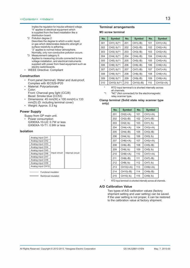
• WEEE Directive: Compliant
Construction• Front panel (terminal): Water and dust-proof,
Complies with IEC529-IP20• Material: Polycarbonate• Color;
Front: Charcoal grey light (CC28) Bezel: Smoke blue (CC53)
• Dimensions: 45 mm(W) x 100 mm(H) x 133 mm(D) (D: including terminal cover)
• Weight: Approx. 0.3 kg
Power SupplySuppy from GP main unit.• Power consumption GX90XA-10-U2: 0.7W or less GX90XA-10-T1: 0.9W or less
Isolation
Functional insulation
Reinforced insulation
Analog input CH1Analog input CH2Analog input CH3Analog input CH4Analog input CH5Analog input CH6Analog input CH7Analog input CH8Analog input CH9Analog input CH10
Input circuit Internal circuit
Terminal arrangementsM3 screw terminal
No. Symbol No. Symbol No. Symbol301 CH1( /b)*1 201 CH1(-/B) 101 CH1(+/A)
302 CH2( /b)*1 202 CH2(-/B) 102 CH2(+/A)
303 CH3( /b)*1 203 CH3(-/B) 103 CH3(+/A)
304 CH4( /b)*1 204 CH4(-/B) 104 CH4(+/A)
305 CH5( /b)*1 205 CH5(-/B) 105 CH5(+/A)
306 CH6( /b)*1 206 CH6(-/B) 106 CH6(+/A)
307 CH7( /b)*1 207 CH7(-/B) 107 CH7(+/A)
308 CH8( /b)*1 208 CH8(-/B) 108 CH8(+/A)
309 CH9( /b)*1 209 CH9(-/B) 109 CH9(+/A)
310 CH10( /b)*1 210 CH10(-/B) 110 CH10(+/A)
* RTD input terminal b is shorted internally across all channels.
*1 "NC" (Not connected) for the electromagnetic relay scanner type.
Clamp terminal (Solid state relay scanner type only)
No. Symbol No. Symbol201 CH2(+/A) 101 CH1(+/A)
202 CH2(-/B) 102 CH1(-/B)
203 CH2( /b) 103 CH1( /b)
204 CH4(+/A) 104 CH3(+/A)
205 CH4(-/B) 105 CH3(-/B)
206 CH4( /b) 106 CH3( /b)
207 CH6(+/A) 107 CH5(+/A)
208 CH6(-/B) 108 CH5(-/B)
209 CH6( /b) 109 CH5( /b)
210 CH8(+/A) 110 CH7(+/A)
211 CH8(-/B) 111 CH7(-/B)
212 CH8( /b) 112 CH7( /b)
213 CH10(+/A) 113 CH9(+/A)
214 CH10(-/B) 114 CH9(-/B)
215 CH10( /b) 115 CH9( /b)
* RTD input terminal b is shorted internally across all channels.
A/D Calibration Value Two types of A/D calibration values (factory
shipment setting and user setting) can be saved. If the user setting is not proper, it can be restored to the calibration value at factory shipment.

14
All Rights Reserved. Copyright © 2012-2013, Yokogawa Electric Corporation
<<Contents>> <<Index>>
GS 04L52B01-01EN May. 7, 2013-00
External DimensionsM3 screw terminal
107.
1(4.
22)
26(1
.02)
92(3
.62)
100(
3.94
)3(
0.12
)8(
0.31
)
(0.0
7)1.
9
45.1(1.78)
43.8(1.72)
Unit: mm(approx. inch)
Clamp terminal
107.
1(4.
22)
26(1
.02)
92(3
.62)
100(
3.94
)3(
0.12
)8(
0.31
)
(0.0
7)1.
9
45.1(1.78)
43.8(1.72)
Unit: mm(approx. inch)
Normal Operating ConditionsSame as the GP main unit
Transport and Storage ConditionsSame as the GP main unit
Effects of Operating Conditions• Influence of ambient temperature: variation against a
change of 10 °C at an accumulation time of 16.67 ms or more ± (0.05% of rdg + 0.05%) or below KpvsAu7Fe, PR20-40: ±(0.05% of rdg + 0.1%) or below, Cu10Ω: ±(0.2% of rdg + 0.1 °C) or below No reference contact accuracy is guaranteed.
• Influence of power supply voltage variation: Accuracy is satisfied in the range of rated power supply voltage.
• Influence of external magnetic field: Variations against an AC external magnetic field (50/60 Hz, 400 A/m) are ±(0.1% of rdg+ 0 .1%) or below.
15<<Contents>> <<Index>>
All Rights Reserved. Copyright © 2012-2013, Yokogawa Electric Corporation GS 04L52B01-01EN May. 7, 2013-00
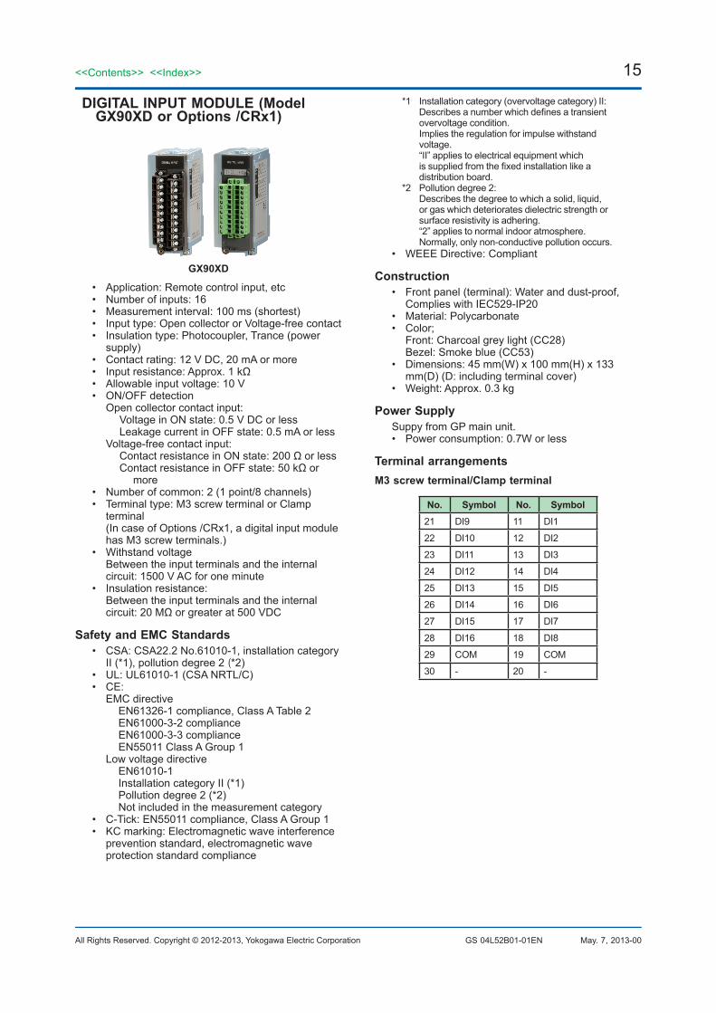
DIGITAL INPUT MODULE (Model GX90XD or Options /CRx1)
GX90XD
• Application: Remote control input, etc• Number of inputs: 16• Measurement interval: 100 ms (shortest)• Input type: Open collector or Voltage-free contact• Insulation type: Photocoupler, Trance (power
supply)• Contact rating: 12 V DC, 20 mA or more• Input resistance: Approx. 1 kΩ• Allowable input voltage: 10 V• ON/OFF detection Open collector contact input:
Voltage in ON state: 0.5 V DC or lessLeakage current in OFF state: 0.5 mA or less
Voltage-free contact input:Contact resistance in ON state: 200 Ω or lessContact resistance in OFF state: 50 kΩ or
more• Number of common: 2 (1 point/8 channels)• Terminal type: M3 screw terminal or Clamp
terminal (In case of Options /CRx1, a digital input module has M3 screw terminals.)
• Withstand voltage Between the input terminals and the internal
circuit: 1500 V AC for one minute• Insulation resistance:
Between the input terminals and the internal circuit: 20 MΩ or greater at 500 VDC
Safety and EMC Standards• CSA: CSA22.2 No.61010-1, installation category
II (*1), pollution degree 2 (*2)• UL: UL61010-1 (CSA NRTL/C)• CE: EMC directive EN61326-1 compliance, Class A Table 2 EN61000-3-2 compliance EN61000-3-3 compliance EN55011 Class A Group 1 Low voltage directive EN61010-1 Installation category II (*1) Pollution degree 2 (*2) Not included in the measurement category• C-Tick: EN55011 compliance, Class A Group 1• KC marking: Electromagnetic wave interference
prevention standard, electromagnetic wave protection standard compliance
*1 Installation category (overvoltage category) II: Describes a number which defines a transient
overvoltage condition. Implies the regulation for impulse withstand
voltage. “II” applies to electrical equipment which
is supplied from the fixed installation like a distribution board.
*2 Pollution degree 2: Describes the degree to which a solid, liquid,
or gas which deteriorates dielectric strength or surface resistivity is adhering.
“2” applies to normal indoor atmosphere. Normally, only non-conductive pollution occurs.
• WEEE Directive: Compliant
Construction• Front panel (terminal): Water and dust-proof,
Complies with IEC529-IP20• Material: Polycarbonate• Color;
Front: Charcoal grey light (CC28) Bezel: Smoke blue (CC53)
• Dimensions: 45 mm(W) x 100 mm(H) x 133 mm(D) (D: including terminal cover)
• Weight: Approx. 0.3 kg
Power SupplySuppy from GP main unit.• Power consumption: 0.7W or less
Terminal arrangementsM3 screw terminal/Clamp terminal
No. Symbol No. Symbol21 DI9 11 DI1
22 DI10 12 DI2
23 DI11 13 DI3
24 DI12 14 DI4
25 DI13 15 DI5
26 DI14 16 DI6
27 DI15 17 DI7
28 DI16 18 DI8
29 COM 19 COM
30 - 20 -
16
All Rights Reserved. Copyright © 2012-2013, Yokogawa Electric Corporation
<<Contents>> <<Index>>
GS 04L52B01-01EN May. 7, 2013-00
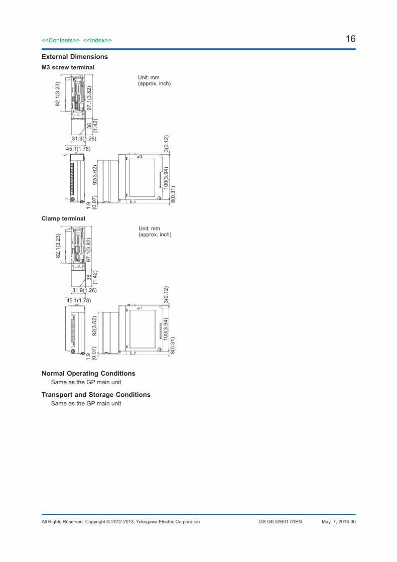
External DimensionsM3 screw terminal
97.1
(3.8
2)
82.1
(3.2
3)
36(1
.42)
92(3
.62)
100(
3.94
)3(
0.12
)8(
0.31
)
(0.0
7)1.
9
45.1(1.78)
31.9(1.26)
Unit: mm(approx. inch)
Clamp terminal
97.1
(3.8
2)
82.1
(3.2
3)
36(1
.42)
92(3
.62)
100(
3.94
)3(
0.12
)8(
0.31
)
(0.0
7)1.
9
45.1(1.78)
31.9(1.26)
Unit: mm(approx. inch)
Normal Operating ConditionsSame as the GP main unit
Transport and Storage ConditionsSame as the GP main unit

17<<Contents>> <<Index>>
All Rights Reserved. Copyright © 2012-2013, Yokogawa Electric Corporation GS 04L52B01-01EN May. 7, 2013-00
DIGITAL OUTPUT MODULE (Model GX90YD, or Options /CR1x, /CR2x, /CR4x)
GX90YD
• Application: Alarm output, etc• Number of outputs: 6• Output update interval: 100 ms (shortest)• Output type: Relay contact output, SPDT (NO-C-
NC)• Insulation type: Mechanical• Rated load voltage: 24 V DC or 250 V AC or less• Rated load current: 3 A (DC)/3 A (AC), resistance
load, each channel• Min. load voltage/current: 5 V DC• Recommended replacement periods of contact:
Mechanical 5,000,000 more ON-OFF operations Electrical 30,000 more ON-OFF operations (250
V AC 3 A or 24 V DC 3 A, resistance load)• Number of common: 6• Power supply: Not necessary• Terminal type: M3 screw terminal• Withstand voltage Between the output terminals and the internal
circuit: 3000 V AC for one minute• Insulation resistance:
Between the output terminals and the internal circuit: 20 MΩ or greater at 500 VDC
Safety and EMC Standards• Safety and EMC Standards: Same as the digital
input module • WEEE Directive: Compliant
Construction• Front panel (terminal): Water and dust-proof,
Complies with IEC529-IP20• Material: Polycarbonate• Color;
Front: Charcoal grey light (CC28) Bezel: Smoke blue (CC53)
• Dimensions: 45 mm(W) x 100 mm(H) x 133 mm(D) (D: including terminal cover)
• Weight: Approx. 0.3 kg
Power SupplySuppy from GP main unit.• Power consumption: 1.4 W or less
Terminal arrangementsM3 screw terminal
No. Symbol No. Symbol21 DO4 N.C. 11 DO1 N.C.
22 DO4 COM 12 DO1 COM
23 DO4 N.O. 13 DO1 N.O.
24 DO5 N.C. 14 DO2 N.C.
25 DO5 COM 15 DO2 COM
26 DO5 N.O. 16 DO2 N.O.
27 DO6 N.C. 17 DO3 N.C.
28 DO6 COM 18 DO3 COM
29 DO6 N.O. 19 DO3 N.O.
30 - 20 -
External DimensionsM3 screw terminal
97.1
(3.8
2)
82.1
(3.2
3)
36(1
.42)
92(3
.62)
100(
3.94
)3(
0.12
)8(
0.31
)
(0.0
7)1.
9
45.1(1.78)
31.9(1.26)
Unit: mm(approx. inch)
18
All Rights Reserved. Copyright © 2012-2013, Yokogawa Electric Corporation
<<Contents>> <<Index>>
GS 04L52B01-01EN May. 7, 2013-00
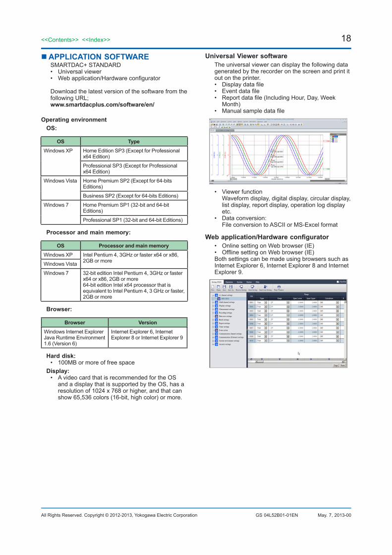
APPLICATION SOFTWARESMARTDAC+ STANDARD• Universal viewer• Web application/Hardware configurator
Download the latest version of the software from the following URL; www.smartdacplus.com/software/en/
Operating environmentOS:
OS TypeWindows XP Home Edition SP3 (Except for Professional
x64 Edition)
Professional SP3 (Except for Professional x64 Edition)
Windows Vista Home Premium SP2 (Except for 64-bits Editions)
Business SP2 (Except for 64-bits Editions)
Windows 7 Home Premium SP1 (32-bit and 64-bit Editions)
Professional SP1 (32-bit and 64-bit Editions)
Processor and main memory:
OS Processor and main memoryWindows XP Intel Pentium 4, 3GHz or faster x64 or x86,
2GB or moreWindows Vista
Windows 7 32-bit edition Intel Pentium 4, 3GHz or faster x64 or x86, 2GB or more64-bit edition Intel x64 processor that is equivalent to Intel Pentium 4, 3 GHz or faster, 2GB or more
Browser:
Browser VersionWindows Internet ExplorerJava Runtime Environment 1.6 (Version 6)
Internet Explorer 6, Internet Explorer 8 or Internet Explorer 9
Hard disk:• 100MB or more of free space
Display:• A video card that is recommended for the OS
and a display that is supported by the OS, has a resolution of 1024 x 768 or higher, and that can show 65,536 colors (16-bit, high color) or more.
Universal Viewer softwareThe universal viewer can display the following data generated by the recorder on the screen and print it out on the printer.• Display data file• Event data file• Report data file (Including Hour, Day, Week
Month)• Manual sample data file
• Viewer function Waveform display, digital display, circular display,
list display, report display, operation log display etc.
• Data conversion: File conversion to ASCII or MS-Excel format
Web application/Hardware configurator• Online setting on Web browser (IE)• Offline setting on Web browser (IE)Both settings can be made using browsers such as Internet Explorer 6, Internet Explorer 8 and Internet Explorer 9.
19<<Contents>> <<Index>>
All Rights Reserved. Copyright © 2012-2013, Yokogawa Electric Corporation GS 04L52B01-01EN May. 7, 2013-00
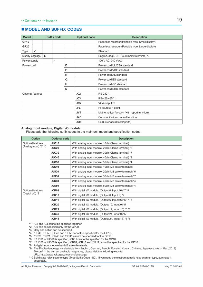
MODEL AND SUFFIX CODES
Model Suffix Code Optional code DescriptionGP10 Paperless recorder (Portable type, Small display)
GP20 Paperless recorder (Portable type, Large display)
Type -1 Standard
Display language E English, degF, DST (summer/winter time) *9
Power supply 1 100 V AC, 240 V AC
Power cord D Power cord UL/CSA standard
F Power cord VDE standard
R Power cord AS standard
Q Power cord BS standard
H Power cord GB standard
N Power cord NBR standard
Optional features /C2 RS-232 *1
/C3 RS-422/485 *1
/D5 VGA output *2
/FL Fail output, 1 point
/MT Mathematical function (with report function)
/MC Communication channel function
/UH USB interface (Host 2 ports)
Analog input module, Digital I/O module:Please add the following suffix codes to the main unit model and specification codes.
Option Optional code DescriptionOptional features (Analog input) *3*10
/UC10 With analog input module, 10ch (Clamp terminal)
/UC20 With analog input module, 20ch (Clamp terminal) *6
/UC30 With analog input module, 30ch (Clamp terminal) *7
/UC40 With analog input module, 40ch (Clamp terminal) *4
/UC50 With analog input module, 50ch (Clamp terminal) *4
/US10 With analog input module, 10ch (M3 screw terminal)
/US20 With analog input module, 20ch (M3 screw terminal) *6
/US30 With analog input module, 30ch (M3 screw terminal) *7
/US40 With analog input module, 40ch (M3 screw terminal) *4
/US50 With analog input module, 50ch (M3 screw terminal) *4
Optional features (Digital I/O) *3
/CR01 With digital I/O module, (Output:0, Input:16) *7 *8
/CR10 With digital I/O module, (Output:6, Input:0) *7
/CR11 With digital I/O module, (Output:6, Input:16) *6 *7 *8
/CR20 With digital I/O module, (Output:12, Input:0) *5
/CR21 With digital I/O module, (Output:12, Input:16) *5 *8
/CR40 With digital I/O module, (Output:24, Input:0) *5
/CR41 With digital I/O module, (Output:24, Input:16) *5 *8
*1 /C2 and /C3 cannot be specified together.*2 /D5 can be specified only for the GP20.*3 Only one option can be specified.*4 /UC40, /UC50, /US40 and /US50 cannot be specified for the GP10.*5 /CR20, /CR21, /CR40 and /CR41 cannot be specified for the GP10.*6 If /UC20 or /US20 is specified, /CR11 cannot be specified for the GP10.*7 If /UC30 or /US30 is specified, /CR01, /CR10 and /CR11 cannot be specified for the GP10.*8 A digital input module has M3 screw terminals.*9 The Display language is selectable from English, German, French, Russian, Korean, Chinese, Japanese. (As of Mar., 2013) To confirm the current available languages, please visit the following website. URL: http://www.yokogawa.com/ns/language/*10 Solid state relay scanner type (Type Suffix Code: -U2). If you need the electromagnetic relay scanner type, purchase it
separately.
20
All Rights Reserved. Copyright © 2012-2013, Yokogawa Electric Corporation
<<Contents>> <<Index>>
GS 04L52B01-01EN
20<<Contents>> <<Index>>
May. 7, 2013-00Subject to change without notice.
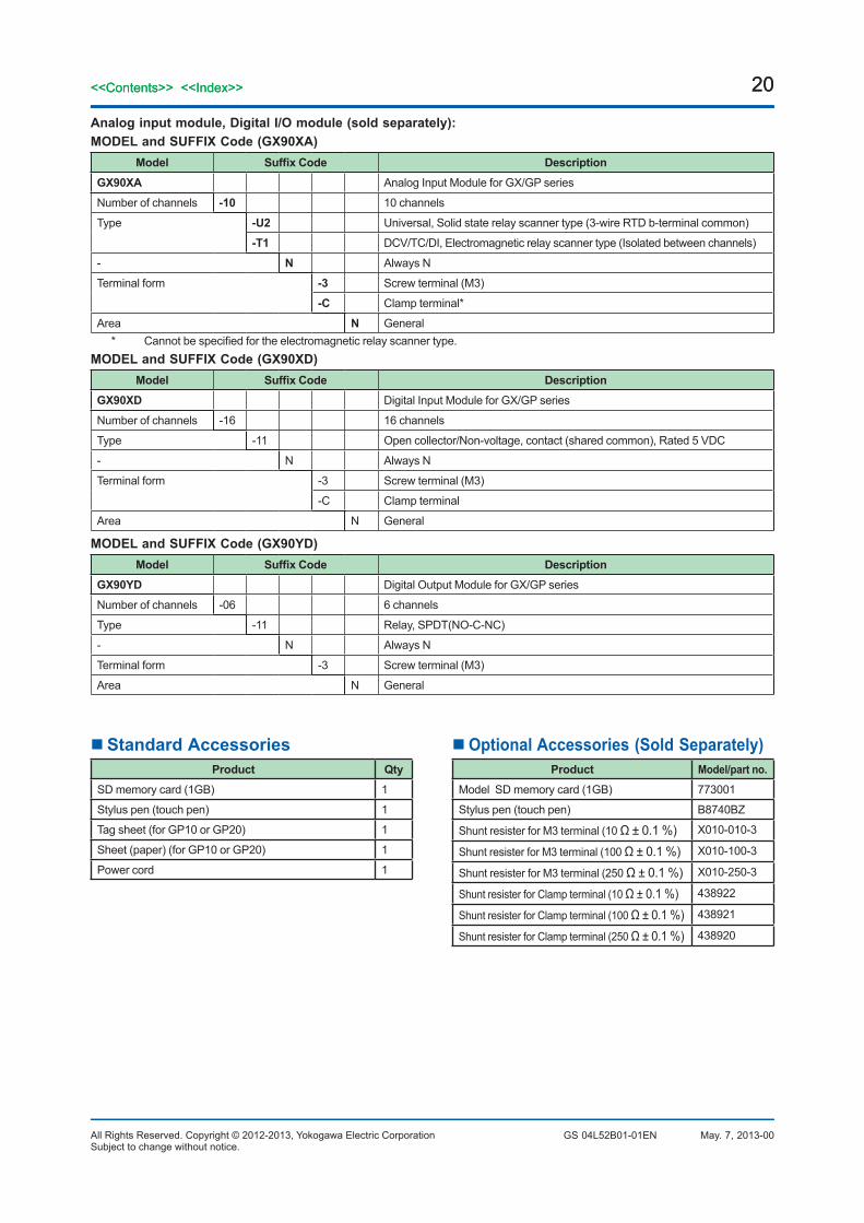
Analog input module, Digital I/O module (sold separately):MODEL and SUFFIX Code (GX90XA)
Model Suffix Code DescriptionGX90XA Analog Input Module for GX/GP series
Number of channels -10 10 channels
Type -U2 Universal, Solid state relay scanner type (3-wire RTD b-terminal common)
-T1 DCV/TC/DI, Electromagnetic relay scanner type (Isolated between channels)
- N Always N
Terminal form -3 Screw terminal (M3)
-C Clamp terminal*
Area N General* Cannot be specified for the electromagnetic relay scanner type.
MODEL and SUFFIX Code (GX90XD)Model Suffix Code Description
GX90XD Digital Input Module for GX/GP series
Number of channels -16 16 channels
Type -11 Open collector/Non-voltage, contact (shared common), Rated 5 VDC
- N Always N
Terminal form -3 Screw terminal (M3)
-C Clamp terminal
Area N General
MODEL and SUFFIX Code (GX90YD)Model Suffix Code Description
GX90YD Digital Output Module for GX/GP series
Number of channels -06 6 channels
Type -11 Relay, SPDT(NO-C-NC)
- N Always N
Terminal form -3 Screw terminal (M3)
Area N General
Standard AccessoriesProduct Qty
SD memory card (1GB) 1
Stylus pen (touch pen) 1
Tag sheet (for GP10 or GP20) 1
Sheet (paper) (for GP10 or GP20) 1
Power cord 1
Optional Accessories (Sold Separately)Product Model/part no.
Model SD memory card (1GB) 773001
Stylus pen (touch pen) B8740BZ
Shunt resister for M3 terminal (10 Ω ± 0.1 %) X010-010-3
Shunt resister for M3 terminal (100 Ω ± 0.1 %) X010-100-3
Shunt resister for M3 terminal (250 Ω ± 0.1 %) X010-250-3
Shunt resister for Clamp terminal (10 Ω ± 0.1 %) 438922
Shunt resister for Clamp terminal (100 Ω ± 0.1 %) 438921
Shunt resister for Clamp terminal (250 Ω ± 0.1 %) 438920

21
All Rights Reserved. Copyright © 2012-2013, Yokogawa Electric Corporation
<<Contents>> <<Index>>
GS 04L52B01-01EN
21<<Contents>> <<Index>>
May. 7, 2013-00Subject to change without notice.
Calibration certificate (sold separately)When ordering the GP10/GP20 with options (analog input), the calibration certificate for the modules is included in and shipped with the calibration certificate of the main unit. When ordering an analog input module separately, each module gets its own calibration certificate (one certificate per module).
Test certificate (QIC, sold separately)When ordering the GP10/GP20 with options (analog/digial I/O), the QIC for each module is included in and shipped with the QIC of the main unit. When ordering analog input modules and digital I/O modules separately, each module gets its own QIC (one QIC per module).
User's ManualProduct user's manuals can be downloaded or viewed at the following URL. To view the user's manual, you need to use Adobe Reader 7 or later by Adobe Systems.URL: www.smartdacplus.com/manual/en/
Product Purchase SpecificationsThe GP10/GP20 is composed of the main unit and I/O modules.There are two ways to purchase I/O modules.One way is to purchase them individually by specifying models GX90XA, GX90XD, and GX90YD.The other way is to purchase them as an option (/UCxx or /USxx). Purchasing them as an option is convenient, but this places limitations on the number of analog inputs that you can obtain.If you want to use more than 50 channels, please purchase the I/O modules individually.
Trademarks The TCP/IP software used in this product and the document for that TCP/IP software are based in part on BSD
networking software, Release 1 licensed from The Regents of the University of California.• SMARTDAC+ is a trademark of Yokogawa Electric Corporation.• Microsoft, MS and Windows are registered trademarks of Microsoft Corporation USA.• Pentium are registered trademarks of Intel Corporation.• Ethernet is a registered trademark of XEROX Corporation.• Modbus is a registered trademark of AEG Schneider.• Kerberos is a trademark of MIT.• Java and Java-related trademarks are trademarks or registered trademarks of Sun Microsystems, Inc. in the United
States and/or other countries.• Other company and/or product names are registered trade mark of their manufactures.