general guidelines for electronic equipment
TRANSCRIPT

MIL-HDBK-454A03 NOVEMBER 2000________________SUPERSEDINGMIL-HDBK-45428 APRIL 1992
DEPARTMENT OF DEFENSEHANDBOOK
GENERAL GUIDELINES FORELECTRONIC EQUIPMENT
This handbook is for guidance only. Do not cite this document as a requirement.
AMSC N/A AREA GDRQDISTRIBUTION STATEMENT A. Approved for public release; distribution is unlimited.
METRIC
Downloaded from http://www.everyspec.com

MIL-HDBK-454A
ii
FOREWORD
1. This handbook is approved for use by all Departments and Agencies of the Department ofDefense
2. This handbook is for guidance only. This handbook cannot be cited as a requirement. If it is,
the contractor does not have to comply. 3. This handbook is the technical baseline for the design and construction of electronic
equipment for the Department of Defense. It captures in one document, under suitablesubject heading, fundamental design guidelines for multiple general electronic specifications.The opportunity to focus on a single document, afforded to contractors, results in substantialsavings to the Government. This handbook was prepared by and is regularly updatedthrough the cooperative efforts of Government and industry. The following Governmentdocuments are intimately associated with this handbook.
MIL-HDBK-2036 General Requirements for Electronic Equipment Specifications. DOD-E-8983 Electronic Equipment, Aerospace, Extended Space Environment,
General Specification for. MIL-HDBK-11991 Electrical, Electronic and Electro-mechanical Equipment, Guided
Missile and Associated Weapon Systems, Design of. MIL-F-18870 Fire Control Equipment, Naval Shipboard, General Specification
for. MIL-PRF-28800 Test Equipment for Use with Electrical and Electronic
Equipment, General Specification for.
4. Beneficial comments (recommendations, additions, deletions) and any pertinent data whichmay be of use in improving this document should be addressed to Defense Supply Center,Columbus, ATTN: DSCC-VSC, 3990 E. Broad St. Columbus, OH 43216, by using theStandardization Document Improvement Proposal (DD Form 1426) appearing at the end ofthis document or by letter.
Downloaded from http://www.everyspec.com

MIL-HDBK-454A
iii
CONTENTS
PARAGRAPH
FOREWORD ii
1. SCOPE 11.1 Guidelines applicable to electronic equipment 11.2 Revision of guidelines 11.2.1 Redating 11.3 Method of reference 11.4 Interrelationship of guidelines 1
2. APPLICABLE DOCUMENTS 12.1 Individual Guidelines 12.1.1 Applicable issues 12.1.2 Copies 12.1.3 Industry addresses 1
3. DEFINITIONS 33.1 Airborne, Space, Aerospace 33.2 Other terms are defined in the individual guidelines
4. GENERAL GUIDELINES 34.1 Application 34.2 Use of selection and application standards 3
5. DETAIL GUIDELINES 35.1 Individual guidelines for electronic equipment follow 3
6. NOTES 36.1 Changes from previous issue 36.2 Subject term (key word) listing 4
Individual Guidelines
Guideline 1 - Safety Design Criteria - Personnel HazardsGuideline 2 - CapacitorsGuideline 3 - FlammabilityGuideline 4 - Fungus-Inert MaterialsGuideline 5 - SolderingGuideline 6 - Bearings
Downloaded from http://www.everyspec.com

MIL-HDBK-454A
iv
Guideline 7 - InterchangeabilityGuideline 8 - Electrical Overload ProtectionGuideline 9 - WorkmanshipGuideline 10 - Electrical ConnectorsGuideline 11 - Insulating Materials, ElectricalGuideline 12 - Fastener HardwareGuideline 13 - Structural WeldingGuideline 14 - Transformers, Inductors, and CoilsGuideline 15 - Metals, Corrosion ResistanceGuideline 16 - Dissimilar MetalsGuideline 17 - Printed WiringGuideline 18 - Derating of Electronic Parts and MaterialsGuideline 19 - TerminationsGuideline 20 - Wire, Hookup, InternalGuideline 21 - CastingsGuideline 22 - Parts Selection and ControlGuideline 23 - AdhesivesGuideline 24 - Welds, Resistance, Electrical InterconnectionsGuideline 25 - Electrical PowerGuideline 26 - Arc-Resistant MaterialsGuideline 27 - BatteriesGuideline 28 - ControlsGuideline 29 - Electron TubesGuideline 30 - Semiconductor DevicesGuideline 31 - Moisture PocketsGuideline 32 - Test ProvisionsGuideline 33 - ResistorsGuideline 34 - NomenclatureGuideline 35 - ReliabilityGuideline 36 - AccessibilityGuideline 37 - Circuit BreakersGuideline 38 - Quartz Crystals and Oscillator UnitsGuideline 39 - Fuses and Fuse HoldersGuideline 40 - ShuntsGuideline 41 - SpringsGuideline 42 - Tuning Dial MechanismsGuideline 43 - LubricantsGuideline 44 - Fibrous Materials, OrganicGuideline 45 - Corona and Electrical Breakdown PreventionGuideline 46 - Motors and Rotary Power ConvertersGuideline 47 - Encapsulation and Embedment (Potting)Guideline 48 - GearsGuideline 49 - HydraulicsGuideline 50 - Indicator LightsGuideline 51 - Meters, Electrical Indicating
Downloaded from http://www.everyspec.com

MIL-HDBK-454A
v
Guideline 52 - Thermal DesignGuideline 53 - Waveguides and Related DevicesGuideline 54 - MaintainabilityGuideline 55 - EnclosuresGuideline 56 - Rotary Servo DevicesGuideline 57 - RelaysGuideline 58 - SwitchesGuideline 59 - BrazingGuideline 60 - Sockets and AccessoriesGuideline 61 - Electromagnetic Interference ControlGuideline 62 - Human EngineeringGuideline 63 - Special ToolsGuideline 64 - Microelectronic DevicesGuideline 65 - Cable, Coaxial (RF)Guideline 66 - Cable, MulticonductorGuideline 67 - MarkingGuideline 68 - Readouts and DisplaysGuideline 69 - Internal Wiring PracticesGuideline 70 - Electrical FiltersGuideline 71 - Cable and Wire, InterconnectionGuideline 72 - SubstitutabilityGuideline 73 - Standard Electronic ModulesGuideline 74 - Grounding, Bonding, and ShieldingGuideline 75 - Electrostatic Discharge ControlGuideline 76 - Fiber OpticsGuideline 77 - Integrated DiagnosticsGuideline 78 - Producibility
Tables
Table 1-I Probable effects of shockTable 1-II Suitable protective measuresTable 4-I Fungi-susceptibility of materialsTable 10-I Abbreviations for thermocouple materialsTable 20-I Wire, electricalTable 21-I General comparison of metallic casting processesTable 26-I Arc-resistant materialsTable 41-I Materials for electrical spring applicationTable 41-II Corrosion resisting steel for springsTable 41-IIICarbon steel for springsTable 50-I Indicator lights and associated itemsTable 53-I Waveguides and related devicesTable 66-I Cable, multiconductorTable 69-I Electrical clearance and leakage (creepage) distancesTable 71-I Wire, electrical, interconnection
Downloaded from http://www.everyspec.com

MIL-HDBK-454A
vi
Table 71-II Cable, multiconductor, interconnection
IndexesIndex I-1 Index of Applicable DocumentsIndex I-2 Subject Index
Downloaded from http://www.everyspec.com

MIL-HDBK-454A
1
1. SCOPE.
1.1 Guidelines applicable to electronic equipment. This handbook provides guidance andlessons learned in the selection of documentation for the design of electronic equipment. Thishandbook is for guidance only. This handbook cannot be cited as a requirement. If it is, thecontractor does not have to comply.
1.2 Revision of guidelines. Revisions of individual guidelines are indicated by a date belowthe guideline number located at the bottom of the page. When the basic document is revised,those guidelines not affected by change retain their existing date.
1.2.1 Redating. Although individual guidelines are reviewed and updated or validated atleast once every eighteen months, guidelines are not redated unless technical changes are made.
1.3. Method of reference. Guidelines contained herein should be referenced by specifyingthis handbook and the guideline number for guidance only.
1.4 Interrelationship of guidelines. Each guideline is intended to cover some discipline inthe design of equipment, such as a procedure, a process or the selection and application of partsand materials. Many of these disciplines, however, cannot retain a clear-cut separation orisolation from others so that when guidelines of MIL-HDBK-454 are referenced in a specificationsome guidelines will undoubtedly have a direct interrelationship with other guidelines. Thisinterrelationship should be taken into consideration when referencing these guidelines.
2. APPLICABLE DOCUMENTS.
2.1 Individual Guidelines. See section 2 of each individual guideline for a listing ofapplicable documents. Documents referenced in the individual guidelines apply to the extentspecified therein.
2.1.1 Applicable issues. Unless otherwise specified, the applicable issues should be thoselisted in that issue of the Department of Defense Index of Specifications and Standards (DODISS)specified in the solicitation. The applicable issue of nongovernment documents should be theissue specified.
2.1.2 Copies. Copies of specifications, standards, drawings, and publications required bycontractors in connection with specific procurement functions should be obtained from theprocuring activity or as directed by the contracting officer.
2.1.3 Industry addresses. Addresses for obtaining documents referenced herein but notobtainable from the Government are as follows:
Downloaded from http://www.everyspec.com

MIL-HDBK-454A
2
AGMA American Gear Manufacturers’ Association1500 King Street, Suite 12Arlington VA 22314
AMS Society of Automotive Engineers, Inc.ARP 400 Commonwealth Drive
Warrendale PA 15096
ANSI American National Standards Institute 11 West 42nd Street
New York NY 10036
ASME American Society of Mechanical Engineers 22 Law Drive P.O. Box 2900
Fairfield NJ 07007-2900
ASM American Society for Metals Metals Park OH 44073
ASTM American Society for Testing and Materials 100 Barr Harbor Drive
West Conshohockan PA 19428-2959
AWS American Welding Society 550 NW LeJeune Road
Miami FL 33126
EIA Electronic Industries Alliance 2500 Wilson Blvd.
Arlington VA 22201-3834
IEEE Institute of Electrical and Electronics Engineers IEEE Service Center
445 Hoes LanePO Box 1331Piscataway NJ 08855-1331
IPC Institute for Interconnecting and Packaging Electronic Circuits 2215 Sanders Rd. Suite 200 South
Northbrook IL 60062
NAS National Standards Association 1200 Quince Orchard Boulevard
Gaithersburg MD 20878
Downloaded from http://www.everyspec.com
MIL-HDBK-454A
3
NFPA National Fire Protection Association Batterymarch Park
Quincy MA 02269-9101
UL Underwriters Laboratories, Incorporated 333 Pfingsten Road
Northbrook IL 60062
3. DEFINITIONS
3.1 Airborne, Space, Aerospace. "Airborne" denotes those applications peculiar to aircraftand missile or other systems designed for operation primarily within the earth's atmosphere;"space" denotes application peculiar to spacecraft and systems designed for operation near orbeyond the upper reaches of the earth's atmosphere; and "aerospace" includes both airborne andspace applications.
3.2 Other terms are defined in the individual guidelines.
4. GENERAL GUIDELINES
4.1 Application. The Guidelines contained herein are intended to provide uniformguidelines applicable to electronic equipment, unless otherwise specified in the Guideline, andshould be incorporated by reference in general equipment specifications. Other documents mayreference Guidelines when applicable.
4.2 Use of selection and application standards. When a selection and application standardis invoked in a guideline, the devices or parts selected should conform to the applicable militaryspecifications referenced in the standard.
5. DETAIL GUIDELINES
5.1 Individual guidelines for electronic equipment follow.
6. NOTES
6.1 Changes from previous issue. Marginal notations are not used in this revision toidentify changes with respect to the previous issue due to the extent of the changes.
Downloaded from http://www.everyspec.com

MIL-HDBK-454A
4
6.2 Subject term (key word) listing.
Cable selection NomenclatureCorona protection Parts selectionEncapsulation Printed wiringFasteners SafetyFlammability SolderingFungus protection Substitutability of partsInterchangeability of parts Thermal designMarking WaveguidesMaterials selection Wire selectionMicroelectronics Workmanship
CONCLUDING MATERIAL
Custodians: Preparing activity:Army - CR DLA - CCNavy - ASAir Force - 11 Project GDRQ-0182
Review activities:Army - AR, AV, MI, TENavy - EC, SH, OSAir Force - 19
Downloaded from http://www.everyspec.com

MIL-HDBK-454A
1-1
GUIDELINE 1
SAFETY DESIGN CRITERIA - PERSONNEL HAZARDS
1. Purpose. This guideline establishes safety design criteria and provides guidelines forpersonnel protection.
2. Applicable Documents.
MIL-STD-464 Interface Standard for Electromagnetic Environmental EffectsRequirements for Systems
MIL-STD-1310 Shipboard Bonding, Grounding, and Other Techniques for Electromagnetic Compatibility and Safety
MIL-STD-1425 Safety Design Requirements for Military Lasers andAssociated Support Equipment
MIL-STD-1472 Human EngineeringDOD Manual 6050.5-M Hazardous Materials Information System ProcedureDOD Instruction 6055.11 Protection of DoD Personal from Exposure to
Radiofrequency Radiation and Military Exempt LasersANSI C95.1 Safety Levels with Respect to Human Exposure to Radio
Frequency Electromagnetic Fields, 3 kHz to 300 GHzANSI C95.2 Radio Frequency Radiation Hazard Warning SymbolANSI N2.1 Radiation SymbolANSI Z136.1 Safe Use of LasersANSI Z535.1 Safety Color CodeANSI Z535.2 Environmental and Facility Safety SignsANSI Z535.3 Criteria for Safety SymbolsANSI Z535.4 Product Safety Signs and LabelsANSI Z535.5 Accident Prevention Tags (for Temporary Hazards)NFPA 70 National Electrical Code10 CFR 20 Code of Federal Regulations, Title 10, Chapter I, Part 2021 CFR 1000-1050 Code of Federal Regulations, Title 21, Chapter I, Parts
1000-105029 CFR 1910 Code of Federal Regulations, Title 29, Chapter XVII, Part
1910ASTM F 1166 Human Engineering Design for Marine Systems, Equipment
and Facilities, Standard Practice for
3. Definitions.
3.1 Battleshort. A switch used to bypass normal interlocks in mission critical equipment;(i.e., equipment which must not be shut down or the mission function will fail) during battleconditions.
3.2 Chassis, electrical equipment. The chassis is a structural item fabricated in such manner as tofacilitate assemblage and interconnection of electrical or electronic items for the specific purpose of
Downloaded from http://www.everyspec.com

MIL-HDBK-454A
1-2
providing a basis for electrical or electronic circuits. It normally has drilled or stamped holes toaccommodate the items but may include only the items necessary for its own mounting and support.
3.3 Commercial off-the-shelf (COTS) equipment. Commercial off-the-shelf equipment thatcan be purchased through commercial retail or wholesale distributors as is (i.e., equipment that isavailable as a cataloged item) or with only minor modifications that does not alter its form, fit orfunctional characteristics.
3.4 Frame. The frame is any construction system fitted and united together, designed for mountingor supporting electrical or electronic parts or units.
3.5 Fail-safe. The design feature of a part, unit or equipment which allows the item to failonly into a non-hazardous mode.
3.6 Interlock. An interlock is an automatic switch which eliminates all power from theequipment when anaccess door, cover or plate is removed.
3.6.1 Bypassable interlock. A bypassable interlock is an automatic switch with a manuallyoperated electrical bypass device to allow equipment maintenance operations on energizedequipment.
3.7 Leakage current. Leakage current is that current which flows through the equipmentconductive paths to a solidly grounded source.
3.8 Procuring activity. A unit of the DoD which originates a procurement document forequipment or hardware.
4. General Guidelines.
4.1 Commercial off-the-shelf (COTS) equipment. Commercial off-the-shelf equipment thathas been listed or certified to an appropriate commercial standard by a Nationally RecognizedTest Laboratory (NRTL) (e.g., Underwriters Laboratories (UL), Canadian Standards Association(CSA), or TUV Rheinland (TUV)) should be considered as having met the provisions of thisrequirement and from a product safety perspective, should be accepted for use without furthermodification. COTS equipment which has any modifications and is required to meet commercialstandards requires recertification by a NRTL.
4.2 Fail-safe. The design and development of all military electronic equipment shouldprovide fail-safe features for safety of personnel during the installation, operation, maintenance,and repair or interchanging of a complete equipment assembly or component parts thereof.
4.3 Bonding in hazardous areas. Electronic equipment to be installed in areas whereexplosive or fire hazards exist should be bonded in accordance with MIL-STD-464 for aerospace
Downloaded from http://www.everyspec.com

MIL-HDBK-454A
1-3
systems, MIL-STD-1310 for shipboard systems, and NFPA 70, chapter 5, for facilities, or asotherwise specified in the detail equipment specification.
4.4 Temperature. At an ambient temperature of 25°C, the operating temperature of controlpanels and operating controls should be not greater than 49°C and not less than 12°C. Thetemperature of other exposed parts subject to contact by operating personnel should not exceed60°C. The temperature of all other exposed surfaces should be not greater than 70°C.
4.5 Electrical. The design should incorporate methods to protect personnel from inadvertentcontact with voltages capable of producing shock hazards.
4.5.1 Power. Means should be provided so that power may be cut off while installing,replacing, or interchanging a complete equipment, assembly, or part thereof. Interface withelectrical power sources should be in accordance with the applicable regulations or requirements.If a main power switch is provided, it should be clearly labeled as such and should cut off allpower to the complete equipment. Equipment that utilizes Uninterruptable Power Supplies(UPS) should have provisions to isolate the supply from the equipment.
4.5.2 Ground. The design and construction of equipment, excluding self-poweredequipment, should insure that all external parts, surfaces, and shields, exclusive of antenna andtransmission line terminals, are at ground potential at all times during normal operation. Thedesign should include consideration of ground currents and voltage limits (possible arcing)established on a basis of hazardous location. Antenna and transmission line terminals should be atground potential, except for Radio Frequency (rf) energy on their external surfaces.
4.5.2.1 Self-powered equipment. Self-powered equipment should have all external surfacesat the same potential.
4.5.2.2 Grounding methods. Plugs for use with metal cased portable tools and equipmentshould have provisions for automatically grounding the metal frame or case of tools andequipment when the plug is mated with receptacle, and the grounding pin should make first, breaklast. Ground connections to shields, hinges, and other mechanical parts should not be used tocomplete electrical circuits. Any external or interconnecting cable, where a ground is part of thecircuit, should carry a ground wire in the cable terminated at both ends in the same manner as theother conductors. In no case, except with coaxial cables, should the shield be depended upon fora current-carrying ground connection. Static and safety grounds should not be used to completeelectrical circuits. A point on the electrically conductive chassis or equipment frame should serveas the common tie point for static and safety grounding. The path from the tie point to groundshould:
a. Be continuous and permanent.
b. Have ample carrying capacity to conduct safely any fault currents that may be expected, tobe imposed on it by internally generated faults.
Downloaded from http://www.everyspec.com
MIL-HDBK-454A
1-4
c. Have impedance sufficiently low to limit the potential above ground and to facilitate theoperation of the over current devices in the circuits, and;
d. Have sufficient mechanical strength of the material to minimize possibility of grounddisconnection.
4.5.2.3 Hinged or slide-mounted panels and doors. Hinges or slides should not be used forgrounding paths. Panels and doors containing meters, switches, test points, etc., should beattached or hinged in such a manner as to insure that they are at the same ground potential as theequipment in which they are mounted, whether in a closed or open position. A ground should beconsidered satisfactory if the electrical connection between the door or panel and the system tiepoint exhibits a resistance of 0.1 ohm or less and has sufficient capacity to insure the reliable andimmediate tripping of equipment over-current protection devices.
4.5.2.4 Shielding. Except where a conflict with single-point shield grounding guidelineswould be created, shielding on wire or cable should be grounded to the chassis or frame. Theshielding should be secured to prevent it from contacting exposed current-carrying parts orgrounding to the chassis or frame at any point other than the ground termination. The shieldingshould end at a sufficient distance from exposed conductors to prevent shorting or arcing betweenthe conductor and the shielding.
4.5.2.5 Leakage current. The equipment leakage current should not exceed 3.5 milliamperesdc or rms. When excessive leakage currents are required by design or operational requirements,redundant grounding or double insulation methods should be incorporated.
4.5.3 Accidental contact. The design should incorporate methods to protect personnel fromaccidental contact with voltages in excess of 30 volts rms. or dc during normal operation of acomplete equipment.
4.5.3.1 Guards and barriers. All contacts, terminals and like devices having voltages greaterthan 30 volts rms or dc with respect to ground should be guarded from accidental contact bypersonnel if such points are exposed to contact during direct support or operator maintenance.Guards or barriers may be provided with test probe holes where maintenance testing is required.
4.5.3.2 High voltage guarding. Assemblies operating at potentials in excess of 500 voltsshould be completely enclosed from the remainder of the assembly and equipped with non-bypassable interlocks.
4.5.3.3 Voltage measurement. When the operation or maintenance of equipment employingpotentials in excess of 300 volts peak could require that these voltages be measured, theequipment should be provided with test points so that these voltages can be measured at arelatively low potential level. In no case should the potential exceed 300 volts peak relative toground. Test points with voltages above 30 volts should have the conducting material recessed adistance no less than the diameter of the probe hole and a minimum of 1.5 mm. If a voltage
Downloaded from http://www.everyspec.com

MIL-HDBK-454A
1-5
divider is used, the voltage divider resistance between the test point and ground should consist ofat least two resistors of equal value in parallel.
4.5.3.4 Guarding of RF voltages. Transmitter output terminals, antennas and other devicesthat carry sufficient rf voltage to burn or injure personnel should be protected from accidentalcontact in the same manner as for ac voltages greater than 30 volts rms. (see 4.5.3.1.)
4.5.3.5 Main power switch. The power input side of the main power switch and theincoming power line connections should be given physical protection against accidental contact.
4.5.4 Protective devices.
4.5.4.1 Interlocks. When a unit is provided with access doors, covers or plates, these accesspoints should be interlocked as follows:
a. No interlocks are required when all potentials between 30 and 500 volts are completelyprotected with guards or barriers to prevent accidental contact under all conditions of operationor any level of maintenance.
b. Bypassable interlocks are required when voltages in excess of 30 volts are exposed as theresult of an access door, cover, or plate being opened. Note that these internal voltages areallowed to be unguarded only if they are not exposed during direct support or operatormaintenance. The bypass device should be of such design that closing the associated door, coveror plate will automatically open the bypass device and leave the interlock in position to functionnormally. Visual means should be provided to indicate when the interlock is bypassed.
c. Non-bypassable interlocks are required when any voltage in excess of 500 volts is exposedas a result of an access door, cover or plate being opened.
4.5.4.2 Battle short indicator. In equipment with battleshort circuitry, an audio and visualwarning system should be installed in the equipment. The visual warning should be clearly visibleto operating personal. The audio warning should provide a means for manual silencing andautomatic reset. Catastrophic fault interlocks should not be bypassed.
4.5.4.3 Safety switches. Safety switches, which will deactivate associated mechanical driveunits, should be provided for the purpose of disconnecting these units without disconnecting otherparts of the equipment. Such remotely located units and assemblies should have provision fornon-overrideable safety switches to allow independent disconnection in the associated equipment.
4.5.5 Discharging devices.
4.5.5.1 Automatic discharge devices. High voltage circuits and capacitors should beprovided with discharging devices unless they discharge to 30 volts or less within two secondsafter power removal. The particular discharging device that is chosen should insure that thecapacitor or high voltage circuit is discharged to 30 volts or less within two seconds. These
Downloaded from http://www.everyspec.com

MIL-HDBK-454A
1-6
protective devices should be positive acting, highly reliable, and should actuate automaticallyeither by mechanical release or by electrical solenoid when the door or cover is opened. Whenresistive bleeder networks are used to discharge capacitors, the bleeder network should consist ofat least two equal valued resistors in parallel.
4.5.5.2 Shorting rods. Shorting rods should be provided with all transmitting equipmentwhere voltages are in excess of 70 volts rms or dc. Where size permits, shorting rods should bestored within the transmitting equipment, permanently attached, and readily accessible tomaintenance personnel. The permanently attached rod should be connected through a flexiblestranded copper wire (covered with a transparent sleeving) to the stud provided at the transmittermain frame. Where size does not permit internal storage of the shorting rod, a grounding studshould be provided to permit attachment of a portable shorting rod. The connection to the studshould be such that accidental loosening or high resistance to the ground is prevented.
4.5.6 Connectors. Connectors used in multiple electric circuits should be selected topreclude mismating. Where design considerations require plug and receptacles of similarconfiguration in close proximity, the mating plugs and receptacles should be suitably coded ormarked to clearly indicate the mating connectors. Plugs and receptacles should not be of similarconfiguration if the major unit contains explosive items. The design of the connector should besuch that the operator is not exposed to electrical shock or burns when normal disconnectmethods are used. Exposed pin contacts should not be energized (hot) after being disconnectedfrom the socket contacts.
4.6 Radiation. The design of all equipment for which a federal standard exists under 21 CFRPt. 1000 - 1050, “ The Radiation Control for Health and Safety Act of 1968”, should conform tothe appropriate federal standard.
4.6.1 Microwave and rf radiation. All electronic equipment or electrical devices capable ofemitting microwave or RF radiation between 3 kHz and 300 GHz should be so designed,fabricated, shielded and operated as to avoid overexposure of personnel. Exposure to RFradiation should meet the Controlled and/or Uncontrolled environment Maximum PermissibleExposure Levels called out in IEEE/ANSI C95.1. In areas where unintended radiation levelsexist, equipment design and installation in any unrestricted area accessible to personnel shouldmeet the Uncontrolled environment requirements of IEEE/ANSI C95.1. Shields, covers, doors,etc, which when opened or removed will allow microwave and rf radiation to exceed the above,should be provided with non-bypassable interlocks.
4.6.2 X radiation. All electronic or electrical devices capable of producing X radiationshould be so designed, fabricated, shielded and operated as to keep personnel exposure as low asreasonably achievable. For equipment and installation design, shielding guidelines should bemaintained at all times which limit radiation levels to not greater than 2 milliroentgens (mr) in anyone hour and 100 mr in any 7 consecutive days at the operator position or within 5cm from theequipment (whichever is closer) in any unrestricted area accessible to personnel. In addition,these levels should be reduced whenever necessary to ensure that exposed personnel never receivean absorbed dose to the whole body or any critical organ in excess of 125 millirem per calendar
Downloaded from http://www.everyspec.com

MIL-HDBK-454A
1-7
quarter or 500 millirem per year. Other exposure should be based on application criteria andlimits as required by Nuclear Regulatory Commission Rules and Regulations, 10 CFR 20; OSHARegulations, 29 CFR 1910.96; and FDA Regulation, 21 CFR, chapter I, subchapter J,Radiological Health. Equipment which, when shields, covers, doors, etc, are removed, will allowX radiation to exceed 2.0 mr per hour should be provided with nonbypassable interlocks.
4.6.3 Laser radiation. Laser equipment and system design, installation, and operational andmaintenance procedures should conform to 21 CFR 1040 and ANSI Z136.1. If these cannot bemet because of operational requirements, an exemption should be requested from the FDAthrough the procuring activity, and applicable military laser safety requirements in MIL-STD-1425 must be considered.
4.7 Mechanical. The design of the equipment should provide personnel maximum accessand safety while installing, operating, and maintaining the equipment. Equipment design shouldinclude provisions to prevent accidental pulling out of drawers or rack mounted equipmentcomponents. Suitable protection should be provided to prevent contact with moving mechanicalparts such as gears, fans, and belts when the equipment is complete and operating. Sharpprojections on cabinets, doors, and similar parts should be avoided. Doors or hinged coversshould be rounded at the corners and provided with stops to hold them open.
4.7.1 Mechanical interconnection. The design should provide positive means to prevent theinadvertent reversing or mismating of fittings; couplings; fuel, oil, hydraulic, and pneumatic lines;and mechanical linkage. When prevention of mismating by design consideration is not feasible,coding or marking should be employed when approved by the procuring activity. Coding andmarking will not be approved as a substitute for proper design or items involving explosive,emergency, or safety critical systems.
4.7.2 Power switch location. Equipment power switches should be selected and located sothat accidental contact by personnel will not operate the switch.
4.7.3 Cathode ray tubes. Provision should be incorporated to protect personnel from injurydue to implosion of cathode ray tubes.
4.7.4 Battery Enclosures. Battery Enclosures should be vented. The enclosure designshould prevent shattering, or fragmenting of enclosure parts or covers in the event of a violent gasventing or rupture of battery cells causing explosive high pressure within the compartment.
4.8 Equipment safety markings. Danger, warning, caution, signs, labels, tags and markingsshould be used to warn of specific hazards such as voltage, current, thermal, or physical. Thesigns, labels, tags, and markings should be as permanent as the normal life expectancy of theequipment on which they are affixed. Guards, barriers, and access doors, covers or plates shouldbe marked to indicate the hazard which may be present upon removal of such devices. Whenpossible, marking should be located such that it is not removed when the barrier or access door isremoved. Additionally, hazards internal to a unit should be marked adjacent to hazards if they are
Downloaded from http://www.everyspec.com

MIL-HDBK-454A
1-8
significantly different from those of surrounding items. Such a case would be a high voltageterminal in a group of low voltage devices.
a. Physical hazards should be marked with color codes in accordance with ANSI Z535.1where applicable to electronic equipment.
b. For potentials between 70 and 500 volts, warning signs, labels, or tags should be inaccordance with ANSI Z535.3, ANSI Z535.4, or ANSI Z535.5 contain the single word"WARNING”, and the maximum voltage applicable (i.e., 110VAC).
c. For potentials in excess of 500 volts, warning signs, labels or tags should be in accordancewith ANSI Z535.3, ANSI Z535.4, or ANSI Z535.5 contain the single word "DANGER”, thedescriptive words “High Voltage” and the maximum voltage applicable (i.e., High Voltage 550VAC).
d. Microwave or RF radiation warning signs, labels or tags should be in accordance withANSI Z535.3, ANSI Z535.4, or ANSI Z535.5 and ANSI C95.2. Labels should be provided onall radiation shields to warn personnel of the radiation hazards involved upon removal thereof.Any item, which can emit radiation levels in excess of those specified in 4.6.1, should be labeled.Minimum safe clearance distances should be clearly marked. Warning signs should be posted inall areas having electronic equipment designed to operate between 3 kHz and 300 GHz withintended electromagnetic radiation levels exceeding those in 4.6.1.
e. Laser labels
(1) Laser labels should be in accordance with 21 CFR 1040.
(2) Military exempt laser labels: A permanent label should be affixed on all military lasersystems that have been certified exempt from 21 CFR 1040 (Performance Standards forLight-Emitting Products). The label tags should be in accordance with ANSI Z535.3, ANSIZ535.4, or ANSI Z535.5, should use the single word caution, and should read:
CAUTION
This electronic product has been exempted from FDA radiation safety performance standards,prescribed in the Code of Federal Regulations, title 21, chapter I, subchapter J, pursuant toexemption no. 76 EL-01 DOD issued on 26 July 1976. This product should not be used withoutadequate protective devices or procedures.
f. Shields which protect personnel from X radiation should be labeled in accordance with 10CFR 20.
g. Coding for accident prevention tags should be in accordance with ANSI Z535.5.
h. Coding for safety labels on equipment should be in accordance with ANSI Z535.4.
Downloaded from http://www.everyspec.com
MIL-HDBK-454A
1-9
i. Coding for safety signs regarding facilities or the environment should be in accordancewith ANSI Z535.3.
j. The marking or labeling of commodities containing radioactive materials should be inaccordance with 10 CFR 20.
k. Ionizing radiation hazard symbols should be in accordance with ANSI N2.1.
l. Symbols used on hazard warning signs, labels, tags should be IAW ANSI Z535.2.
4.9 Hazardous and restricted materials.
4.9.1 Gases or fumes. The materials, as installed in the equipment and under serviceconditions specified in the equipment specification, should not liberate gases which combine withthe atmosphere to form an acid or corrosive alkali, nor should they liberate toxic or corrosivefumes which would be detrimental to the performance of the equipment or health of personnel.The materials also should not liberate gases which will produce an explosive atmosphere.
4.9.2 Mercury. Materials and parts containing mercury should not be used unless use ofmercury is specifically required or approved by the procuring activity.
4.9.3 Radioactive materials. Use of radioactive materials should conform to NuclearRegulatory Commission regulations and should require approval of the procuring activity.Radium should not be used to achieve self-luminosity.
4.9.4 Glass fibers. Glass fiber materials should not be used as the outer surface or coveringon cables, wire or other items where they may cause skin irritation to operating personnel. Whenmaintenance procedures require access to glass fibers, such as insulation, a proper caution noteshould be provided.
4.9.5 Cadmium. Cadmium plating and devices using cadmium should not be used unlessspecifically approved by the procuring activity.
5. Detail Guidelines.
5.1 Human engineering. Human engineering factors affecting safety should be consideredwhen establishing general or detailed design criteria. Rigorous detailed operational ormaintenance procedures are not acceptable substitutes for an inherently safe design. Hazard andsafety requirements of MIL-STD-1472 or ASTM F 1166 (for marine systems, equipment andfacilities) should be used as a guide.
5.2 Electrical. Proper instructions in accident prevention and first-aid procedures should begiven to all persons engaged in electrical work to fully inform them of the hazards involved.
Downloaded from http://www.everyspec.com

MIL-HDBK-454A
1-10
5.2.1 Shock hazards. Current rather than voltage is the most important variable inestablishing the criterion for shock intensity. Three factors that determine the severity ofelectrical shock are: (1) quantity of current flowing through the body; (2) path of current throughthe body; and (3) duration of time that the current flows through the body. The voltage necessaryto produce the fatal current is dependent upon the resistance of the body, contact conditions, andthe path through the body. See table 1-I. Sufficient current passing through any part of the bodywill cause severe burns and hemorrhages. However, relatively small currents can be lethal if thepath includes a vital part of the body, such as the heart or lungs. Electrical burns are usually oftwo types, those produced by heat of the arc which occurs when the body touches a high-voltagecircuit, and those caused by passage of electrical current through the skin and tissue. Whilecurrent is the primary factor which determines shock severity, protection guidelines are basedupon the voltage involved to simplify their application. In cases where the maximum currentwhich can flow from a point is less than the values shown in table 1-I for reflex action, protectionguidelines may be relaxed.
TABLE 1-I. Probable effects of shock.
Current values(milliamperes)
AC DC Effects25 Hz to 400 Hz
0-1 0-4 Perception1-4 4-15 Surprise4-21 15-80 Reflex action
21-40 80-160 Muscularinhibition
40-100 160-300 Respiratoryblock
Over 100 Over300
Usually fatal
5.2.2 Insulation of controls. All control shafts and bushings thereof should be groundedwhenever practicable. Alternatively, the control knobs or levers and all attachment screws thatcan be contacted during use should be electrically insulated from the shaft.
5.2.3 Grounding to chassis. Ground connection to an electrically conductive chassis orframe should be mechanically secured by soldering to a spot welded terminal lug or to a portionof the chassis or frame that has been formed into a soldering lug, or by use of a terminal on theground wire and then securing the terminal by a screw, nut, and lock-washer. The screw shouldfit in a tapped hole in the chassis or frame or it should be held in a through-hole by a nut. Whenthe chassis or frame is made of steel, the metal around the screw hole should be plated or tinnedto provide a corrosion resistant connection. When aluminum alloys are used, the metal aroundthe grounding screw or bolthole may be covered with a corrosion resistant surface film only if theresistance through the film is not more than 0.002 ohm. Hardware used for mounting of meters,switches, test points, etc., should be grounded, whenever possible.
Downloaded from http://www.everyspec.com

MIL-HDBK-454A
1-11
5.2.4 Accidental contact. Suitable protective measures are defined in table 1-II.
5.2.4.1 High current protection. Power sources capable of supplying high current can behazardous regardless of the voltage at which they operate because of the arcing and heatgenerated if an accidental short circuit occurs. All power buses supplying 25 amperes or overshould be protected against accidental short-circuiting by tools, jewelry or removable conductiveassemblies. This may be accomplished by one or more of the following:
a. Use of guards and barriers;
b. Sufficient space separation to prevent short circuits;
c. Hazard warning - signs and Labels.
5.2.4.2 Interlocks. Various equipment designs require different approaches to the use ofinterlocks. Interlock use does not modify any other guidelines of this handbook and must beconsistent with equipment or system specifications. Equipment sub-assemblies operating inexcess of 500 volts should be considered guarded from accidental contact only if they arecompletely enclosed from the remainder of the equipment and are separately protected by non-bypassable interlocks. (An example of an equipment where such compartmentalization isdesirable is a display unit which utilizes a high voltage power supply for a cathode ray tube.)Modularized or sealed high voltage assemblies which are opened only at depot level are exemptfrom interlocking guidelines when approved by the procuring activity.
5.2.4.3 Permanent terminations. Terminations such as soldered connections to transformers,connectors, splices, etc., which are normally permanent and not used during routine maintenancetesting, may be protected by permanent insulation such as shrink sleeving, tubing, insulatingshields, etc., provided the material is rated for the potential exposed voltage.
5.3 Mechanical. Design of rack-mounted equipment should maintain the center of gravity aslow as possible to minimize tipping over.
5.4 Marking. DOD 6050.5 references known electronic items which require marking andmay be used as a guide.
5.5 Materials. Certain chemicals have been identified in the Occupational Safety and HealthAct (OSHA) as cancer-producing substances (carcinogens). Before using any materials whichmight contain these chemicals, they should be evaluated in accordance with 29 CFR 1910.
Downloaded from http://www.everyspec.com

MIL-HDBK-454A
1-12
TABLE 1-II. Suitable protective measures. 1/
Type of protection 2/
Voltage rangeMarking Interlocks Discharge devices
Guardsand Enclosures Cautio
nDanger Non- 4/ Shorting
None barriers (4.5.3.2 Bypassable bypassable Automatic rods3/ (4.5.3.1) 4.5.4.1 (4.8b) (4.8c) (4.5.4.1b) (4.5.4.1c) (4.5.5.1) (4.5.5.1)
0 - 30 Volts X> 30 - 70 Volts X X X
> 70 - 500 Volts X X X X X> 500 Volts X X X X X X
1/ Table is for reference only. See applicable paragraph for guidance.
2/ Confine the application of headings to voltage ranges indicated. More than oneoption may be available on design guidance.
3/ Although no specific guidance exist for servicing 0-30 volts, designs should bereviewed for possible hazards in accordance with table 1-I.
4/ Designs may use non-bypassable interlock applications below 500 volts, but theintent here is to imply complete enclosure.
Downloaded from http://www.everyspec.com

MIL-HDBK-454A
2-1
GUIDELINE 2
CAPACITORS
1. Purpose. This guideline establishes criteria for the selection and application of capacitors.
2. Applicable Documents.
MIL-PRF-39006/22 Capacitors, Fixed, Electrolytic (Non-solid Electrolyte), Tantalum,(Polarized, Sintered Slug), 85 C (Voltage Derated to 125 C),Established Reliability, Style CLR79
MIL-PRF-39006/25 Capacitors, Fixed, Electrolytic (Nonsolid Electrolyte), Tantalum,(Polarized, Sintered Slug) (Extended Range), 85 C (VoltageDerated to 125 C), Established Reliability, Style CLR81
MIL-HDBK-198 Capacitors, Selection and Use of
3. Definitions. Not applicable.
4. General Guidelines.
4.1 Selection. Capacitors should be selected and applied in accordance with MIL-HDBK-198.
4.2 Fixed, Tantalum Electrolytic. For Naval Air Systems Command, the use of wet slugtantalum capacitors (except tantalum cased units in accordance with MIL-PRF-39006/22 andMIL-PRF-39006/25) requires the approval of the procuring activity, and silver cased tantalumcapacitors should not be used.
5. Detail Guidelines. Not applicable.
Downloaded from http://www.everyspec.com

MIL-HDBK-454A
3-1
GUIDELINE 3
FLAMMABILITY
1. Purpose. This guideline establishes criteria for the selection and application of materials withrespect to flammability.
2. Applicable Documents.
MIL-STD-202 Test Method for Electronic and Electrical Component PartsASTM D635 Rate of Burning and/or Extent and Time of Burning of Plastics in a
Horizontal Position, Test Method forASTM D1000 Pressure-Sensitive Adhesive-Coated Tapes Used for Electrical and
Electronic Applications, Standard Test Method forUL 94 Standard for Safety, Test for Flammability of Plastic Materials for
Parts in Devices and Appliances
3. Definitions.
3.1 Flammability. Flammability is a complex characteristic which combines ease of ignition,surface flammability, heat contribution, smoke production, fire gasses, and fire endurance.Flammability is a function of chemical composition, physical configuration, temperature,availability of oxygen, and retardants or additives.
4. General Guidelines.
4.1 Materials. Materials used in military equipment should, in the end item configuration, benoncombustible or fire retardant in the most hazardous conditions of atmosphere, pressure, andtemperature to be expected in the application. Fire retardant additives may be used provided theydo not adversely affect the specified performance guidelines of the basic materials. Fireretardance should not be achieved by use of non-permanent additives to the basic material.
5. Detail Guidelines.
5.1 Flammability test. The test used to determine the flammability of material should be thetest specified in the material specification. Since some materials may change state orcharacteristics relative to flammability during application, tests may be performed on the end itemmaterials mixed/blended/saturated/impregnated/layered and processed to simulate the finalconfiguration in the end equipment usage.
5.2 Other flammability test. If the specification does not have such a test, testing should be inaccordance with ASTM D635, ASTM D1000, or MIL-STD-202, Method 111, as applicable.
Downloaded from http://www.everyspec.com

MIL-HDBK-454A
3-2
5.3 Other materials. Materials not covered by the above tests should be tested in accordancewith a procedure approved by the procuring activity. UL 94 is a useful guide to develop testmethods and offers a comparative scale to define degree of flammability.
Downloaded from http://www.everyspec.com

MIL-HDBK-454A
4-1
GUIDELINE 4
FUNGUS-INERT MATERIALS
1. Purpose. This guideline identifies those materials which are acceptable non-nutrients offungus and establishes conditions under which fungus nutrient materials are acceptable.
2. Applicable Documents
MIL-T-152 Treatment, Moisture and Fungus Resistant, of Communications,Electronic, and Associated Electrical Equipment
MIL-STD-810 Environmental Engineering Considerations and Laboratory Tests29 CFR 1910 Code of Federal Regulations Title 29, Chapter XVII, Part 1910
3. Definitions.
3.1 Fungus-inert material. A material which, in all modified states and grades, is not anutrient to fungi.
3.2 Fungicide. A substance that destroys or inhibits the growth of fungi.
4. General Guidelines.
4.1 Preferred materials. Fungus-inert materials listed in group I of table 4-I are preferred foruse. These materials need not be tested for fungus resistance prior to use. The appearance of aparticular material in table 4-I does not constitute approval for its use except from the viewpointof the resistance of the material to fungi.
4.2 Acceptable materials. Those materials listed in group II of table 4-I may be used,provided it has been demonstrated that they meet the guidelines of 4.4. When materials arecompounded with a permanently effective fungicide in order to meet the fungus test guideline,there should be no loss of the original electronic or physical properties required by the basicmaterial specification. Fungicides containing mercury should not be used.
4.3 Hermetically sealed applications. Fungus nutrient materials may be used untreated withinhermetically sealed enclosures.
4.4 Fungus testing. Group II materials should be subjected to the fungus test specified inMIL-STD-810, method 508, for a period of 28 days. Certification by a qualified laboratory or bythe material producer, based on test data on record that the material meets grade O or grade 1guidelines of table 508-I, method 508, MIL-STD-810, is sufficient evidence of acceptability.
Downloaded from http://www.everyspec.com

MIL-HDBK-454A
4-2
TABLE 4-I. Fungi susceptibility of materials.
Group I - Fungus-inert materials
(Fungus-inert in all modified states and grades)
Acrylics 1/ PolyamideAcrylonitrile-styrene PolycarbonateAcrylonitrile-vinyl-chloride Polyester-glass fiber laminates copolymer Polyethylene, high densityAsbestos (above 0.940)Ceramics Polyethylene terephthalate
Chlorinated polyester PolyimideFluorinated ethylenepropylene copolymer Polymonochlorotrifluoroethylene (FEP) PolypropyleneGlass PolystyreneMetals PolysulfoneMica PolytetrafluoroethylenePlastic laminates: Polyvinylidene chloride Silicone-glass fiber Silicone resin Phenolic-nylon fiber Siloxane-polyolefin polymerDiallyl phthalate Siloxane polystyrenePolyacrylonitrile
Group II - Fungus nutrient materials
(May require treatment to attain fungus resistance)
ABS (acrylonitrile-butadiene-styrene) Polyethylene, low and mediumAcetal resins density (0.940 and below)Cellulose acetate Polymethyl methacrylateCellulose acetate butyrate Polyurethane (the ester typesEpoxy-glass fiber laminates are particularly susceptible)Epoxy-resin PolyricinoleatesLubricants Polyvinyl chlorideMelamine-formaldehyde Polyvinyl chloride-acetateOrganic polysulphides Polyvinyl fluoridePhenol-formaldehyde Rubbers, natural and syntheticPolydichlorostyrene Urea-formaldehyde
1/ Literature shows that under certain conditions polyamides may be attacked by selectivemicro-organisms. However, for military applications, they are considered group I.
Downloaded from http://www.everyspec.com

MIL-HDBK-454A
4-3
5. Detail Guidelines
5.1 Process-related materials. Processing materials to be tested for fungus resistance inaccordance with 4.4, such as paint, ink, coatings, adhesives, lubricants, viscous damping fluids,silicone grease, etc., should be prepared in the form of 50 mm squares or circles no more than 1.6mm thick for testing. Liquid or paste materials should be prepared by impregnating to saturationa sterile sample of glass fabric.
5.2 Parts treatment. When treatment of parts is required to form fungus-resistant materials, aMoisture and Fungus Proofing (MFP) varnish may be applied in accordance with MIL-T-152after the part is cleaned. The MFP varnish should not be applied to any part where the treatmentwill interfere with performance.
5.3 Carcinogens. Certain chemicals have been identified in the Occupational Safety andHealth Act (OSHA) as cancer-producing substances (carcinogens). Before using any materialswhich might contain these chemicals, they should be evaluated in accordance with 29 CFR 1910.Consideration of the toxicity of a substance should be given prior to material selection.
Downloaded from http://www.everyspec.com

MIL-HDBK-454A
5-1
GUIDELINE 5
SOLDERING
1. Purpose. This guideline establishes the basis for soldering of electrical and electronicassemblies and non-electrical soldered connections.
2. Applicable Documents.
ANSI J-STD-001 Requirements for Soldered Electrical and Electronic Assemblies
3. Definitions. Not applicable.
4. General Guidelines
4.1 Soldering of Electrical and Electronic Equipment. Electrical and Electronic equipmentshould be assembled, soldered, and cleaned in accordance with the guidelines of ANSI J-STD-001.
4.2 Workmanship. Workmanship may be checked in accordance with ANSI J-STD-001.
5. Detail Guidelines. Not applicable.
Downloaded from http://www.everyspec.com

MIL-HDBK-454A
6-1
GUIDELINE 6
BEARINGS
1. Purpose. This guideline establishes criteria for the selection and application of bearings.
2. Applicable Documents.
FF-B-171 Bearings, Ball, Annular (General Purpose), MetricFF-B-187 Bearing, Roller, TaperedMIL-B-8942 Bearings, Plain, TFE Lined, Self-AligningMIL-B-8943 Bearings, Journal-Plain and Flanged, TFE LinedMIL-B-8948 Bearing, Plain Rod End, TFE Lined, Self-AligningMIL-B-81793 Bearing, Ball, Annular, for Instruments and Precision Rotating
ComponentsA-A-52401 Bearing, Sleeve (Steel Backed)A-A-52414 Bearing, Roller, ThrustSAE AS13341 Process for Bearing Coating of Anti-friction BearingsSAE AS39901 Bearings, Roller, Needle, Airframe, Antifriction, InchSAE AS81934 Bearing, Sleeve, Plain and Flanged, Self-LubricatingSAE AS81936 Bearing, Plain, Self-Aligning (BeCu, CRES Race)
3. Definitions. Not applicable.
4. General Guidelines.
4.1 Selection and application. Bearings best suited to meet the physical, functional,environmental and service life guidelines of the application should be selected from thoseconforming to one or more of the specifications listed below. Replacement of the bearing shouldbe possible without use of special tools unless such provisions would adversely affect the properfunctioning or service life of the bearing.
FF-B-171 MIL-B-8948 SAE AS39901FF-B-187 MIL-B-81793 SAE AS81934MIL-B-8942 A-A-52414 SAE AS81936MIL-B-8943 A-A-52401
4.2 Lubricant. Adequate lubricant should be provided either within the bearing or externallyin the form of oil reservoirs or grease relubrication facilities except as noted in 4.3. Wherelubricant replenishment is required, precaution should be taken to prevent purged or lost lubricantfrom entering and adversely affecting the operation of the electronic equipment. Where bearingscoated with preservative are installed in closed housings, the preservatives should be compatiblewith the lubricant used in the assembly.
Downloaded from http://www.everyspec.com

MIL-HDBK-454A
6-2
4.3 Unlubricated bearings. Unlubricated bearings or bushings may be used only inapplications where the presence of a lubricant would be undesirable or detrimental and thefunctional, environmental and service life guidelines can be met in this condition.
4.4 Barrier coating. Bearings requiring a barrier coating should be coated in accordancewith SAE AS13341.
4.5 Seals and shields. All rolling element bearings should be adequately protected by seals orshields on the bearing or installed in housings which provide adequate shielding to prevent foreignmatter from entering the bearing.
4.6 Electrical grounding. Ball and roller bearings used for rotating an electrically energizedequipment should be electrically shunted to avoid current flow through the bearings.
4.7. Alignment. Bearings should be located to ensure proper shaft alignment and support.
5. Detail Guidelines.
5.1 Self-lubricating bearings. Permanently lubricated bearings or bushings of plastic,metallic-plastic combinations, or all metallic materials with or without dry film lubricants may beused provided wear products produced during operation will not cause or contribute to failure ofthe electronic equipment or bearings.
5.2 Unlubricated bearings. For selection of low friction, long life, unlubricated bearingsrefer to MIL-B-8942, MIL-B-8943, and MIL-B-8948.
Downloaded from http://www.everyspec.com

MIL-HDBK-454A
7-1
GUIDELINE 7
INTERCHANGEABILITY
1. Purpose. This guideline establishes design criteria to assure the interchangeability of parts,subassemblies, and assemblies.
2. Applicable Documents
MIL-HDBK-505 Definitions of Item Levels, Item Exchangeability, Models, andRelated Terms
MIL-HDBK-1547 Electronic Parts, Materials, and Processes for Space and LaunchVehicles
3. Definitions.
3.1 Assembly, interchangeable item, part, subassembly and substitute item. The termsassembly, interchangeable item, part, subassembly and substitute item are defined inMIL-HDBK-505.
3.2 Standard parts. For Air Force space and launch vehicles, standard parts are as describedin MIL-HDBK-1547. For all other equipments, standard parts are defined in the applicablegeneral specification or contract.
4. General Guidelines.
4.1 Design tolerances. Design tolerances should permit parts, subassemblies and assembliesto be used in their parent assemblies without regard to the source of supply or manufacturer.Parts, subassemblies and assemblies having the full range of dimensions and characteristicspermitted by the specification governing the part, subassembly or assembly should be usable asreplacement items without selection and without departure from the specified performanceguidelines of the parent items.
4.2 Parts and materials. When permission is granted to use a nonstandard part or materialbecause the existing standard part or material is not available, the equipment should be sodesigned that the nonstandard part or material and the standard part or material areinterchangeable. When the specification for the part or material contains substitutability orsuppression information, the design should permit the substitute or superseding parts or materialsto be used interchangeably.
5. Detail Guidelines. Not Applicable.
Downloaded from http://www.everyspec.com

MIL-HDBK-454A
8-1
GUIDELINE 8
ELECTRICAL OVERLOAD PROTECTION
1. Purpose. This guideline establishes the criteria and philosophy for electrical overloadprotection.
2. Applicable Documents.
MIL-HDBK-505 Definitions of Item Levels, Item Exchangeability, Models, andRelated Terms
NFPA 70 National Electrical Code
3. Definitions.
3.1 Class 1 equipment. Ground and shipboard, including test and checkout groundequipment
3.2 Class 2 equipment. Manned aerospace equipment
3.3 Class 3 equipment. Unmanned aerospace equipment
4. General Guidelines. The guidelines specified herein should apply only to equipment andsystems as defined in MIL-HDBK-505 for Class 1 and Class 2 equipment.
4.1 Protection for Class 1 equipment.
4.1.1 Current overload protection. Current overload protection should be provided forprimary circuits. Devices such as fuses, circuit breakers, time delays, cutouts, or solid-statecurrent-interruption devices should be used to open a circuit whenever an overload conditionoccurs. No overcurrent protective device should be connected in series with any conductor whichis grounded at the power source unless the device simultaneously opens all load conductors in thecircuit and no pole operates independently, or as otherwise allowed by the National ElectricalCode, NFPA 70. Protective devices for wired-in equipment should be connected to the load sideof the equipment power switch (main circuit power disconnect). For portable equipment aseparable connector or the attachment plug and receptacle should serve as the main circuit powerdisconnect and the protective device may be on either the line side or the load side of theequipment on-off switch.
4.1.2 Fuses. Where fuses are used, at least one extra fuse of each type and rating usedshould be supplied and attached to the applicable units of the equipment. Panel-mounted fuseposts should be such as to permit renewal of fuses without use of tools.
4.1.3 Circuit breakers. Circuit breakers should give a visual indication when tripped.Holding the switching device closed on an overload should not prevent tripping of the breaker.
Downloaded from http://www.everyspec.com

MIL-HDBK-454A
8-2
Multi-pole circuit breakers should be used for three-phase equipment and should disconnect allphases if an overload occurs in any one phase. Circuit breakers should not be used as switchesunless such breakers have been specifically designed and tested for that type service.
4.2 Protection for Class 2 equipment.
4.2.1 Current overload protection. Current overload protection for the equipment should beprovided by fuses or circuit breakers. Circuit breakers should not be used as switches unless suchbreakers have been specifically designed and tested for that type service.
4.2.2 Spare fuses. When fuses are used, a minimum of one spare fuse for each size andrating but a quantity of not less than 10 percent of the total should be incorporated in theequipment and should be contained in the same compartment.
4.3 Protection for Class 3 equipment. Electrical overload protection should not be providedin individual boxes or systems receiving power.
5. Detail Guidelines.
5.1 Location. Overload protection for the equipment should be provided therein. For Class1 and Class 2 equipment, all protective devices employed in the equipment should be in a readilyaccessible, safe location.
5.2 Resettable circuit protectors. Circuit breakers or other resettable devices should be usedto protect critical circuits, or where predictable overloads or surges occur because of peculiarequipment functions or operator effects which are unavoidable.
Downloaded from http://www.everyspec.com

MIL-HDBK-454A
9-1
GUIDELINE 9
WORKMANSHIP
1. Purpose. This guideline establishes the acceptable workmanship criteria for electronicequipment. This guideline will define workmanship guidelines not normally covered in subsidiaryspecifications or drawings.
2. Applicable Documents. Not applicable.
3. Definitions. Not applicable.
4. General Guidelines.
4.1 Cleaning. After fabrication, parts and assembled equipment should be cleaned ofsmudges; loose, spattered, or excess solder; weld metal; metal chips and mold release agents; orany other foreign material which might detract from the intended operation, function, orappearance of the equipment.
4.2 Threaded parts or devices. Screws, nuts and bolts should show no evidence of crossthreading, mutilation, or detrimental or hazardous burrs, and should be firmly secured.
4.3 Bearing assemblies. Bearing assemblies should be free of rust, discoloration, andimperfections of ground, honed, or lapped surfaces. Contacting surfaces should be free of toolmarks, gouge marks, nicks, or other surface-type defects. There should be no detrimentalinterference, binding, or galling.
4.4 Wiring. Wires and cables should be positioned or protected to avoid contact with roughor irregular surfaces and sharp edges and to avoid damage to conductors or adjacent parts.
4.5 Shielding. Shielding on wires and cables should be secured in a manner that will prevent itfrom contacting or shorting exposed current-carrying parts. The ends of the shielding or braidshould be secured to prevent fraying.
5. Detail Guidelines.
5.1 Containment. The harness and cable form containment means should be neat inappearance, uniformly applied, and positioned to retain critical form factors and breakoutlocations. The containment means (lacing, ties, tiedown straps, etc.) should not cause the wire orcable insulation to deform so that performance characteristics are adversely affected.
5.2 Insulation. There should be no evidence of burns, abrading, or pinch marks in theinsulation that could cause short circuits or leakage.
Downloaded from http://www.everyspec.com

MIL-HDBK-454A
9-2
5.3 Clearance. The clearance between wires or cables and heat generating parts should besufficient to minimize deterioration of the wires or cables.
Downloaded from http://www.everyspec.com

MIL-HDBK-454A
10-1
GUIDELINE 10
ELECTRICAL CONNECTORS
1. Purpose. This guideline establishes criteria for the selection and application of electricalconnectors.
2. Applicable Documents.
MIL-J-641 Jack, Telephone, General Specification forMIL-P-642 Plug, Telephone, and Accessory Screws, General Specification forMIL-DTL-5015 Connectors, Electrical, Circular Threaded, AN Type, General
Specification forMIL-C-21097 Connectors, Electrical, Printed Wiring Board, General Purpose,
General Specification forMIL-C-22992 Connectors, Plugs and Receptacles, Electrical, Waterproof, Quick
Disconnect, Heavy Duty Type, General Specification forMIL-C-29600 Connector, Electrical, Circular, Miniature, Composite, High
Density, Quick Coupling, Environment Resistant, RemovableCrimp Contacts, General Specifications for
MIL-PRF-31031 Connectors, Electrical, Plugs and Receptacles, Coaxial,Radiofrequency, High Reliability, for Flexible and Semirigid Cables,General Specification for
MIL-DTL-38999 Connector, Electrical, Circular, Miniature, High Density, QuickDisconnect (Bayonet, Threaded, and Breech Coupling)Environment Resistant, Removable Crimp and HermeticSolder contacts, General Specifications for
MIL-PRF-39012 Connectors, Coaxial, Radiofrequency, General Specification forMIL-C-39024 Jack, Tip (Test Point, Panel or Printed Wiring Type), General
Specification forMIL-PRF-49142 Connector, Triaxial, Radiofrequency, General Specification forMIL-C-55116 Connectors, Miniature, Audio, Five-Pin and Six-Pin General
Specification forMIL-C-55302 Connectors, Printed Circuit Subassembly and AccessoriesMIL-PRF-55339 Adapters, Connectors, Coaxial, Radio Frequency (Between Series
and Within Series) General Specification forMIL-DTL-83503 Connectors, Electrical, Flat Cable, and/or Printed Wiring Board,
Nonenvironmental, General Specification forMIL-C-83517 Connector, Coaxial, Radiofrequency for Coaxial, Strip or
Microstrip Transmission Line, General Specification forMIL-C-83723 Connector, Electrical Circular, Environment Resistant, Receptacles
and Plugs, General Specification forEIA-297 Cable Connectors for Audio Facilities for Radio Broadcasting
3. Definitions. Not applicable.
Downloaded from http://www.everyspec.com

MIL-HDBK-454A
10-2
4. General Guidelines.
4.1 Selection. Intended use information contained in the individual connector specificationsshould be considered prior to making connector selections. Contact crimp, installing and removaltools should be in accordance with the individual connector specifications. However, contractorsmay use tooling as recommended by the contact or tooling manufacturer provided that thefinished crimp meets all of the performance guidelines of the contact and connector specification.The variety of these tools required within a system should be kept to a minimum. Maintenanceinstructions and other data supplied by the contractor should list the military standard tools andcontacts.
4.2 Audio frequency and communication connectors, special purpose. Connectorsconforming to MIL-C-55116 should be used in audio frequency applications, such as head setsand chest sets, excluding pilots' helmets. For low level, three wire and audio input circuits in fixedplant nontactical sound equipment, connectors conforming to EIA-297 should be used.
4.3 Connectors with thermocouple contacts. All connectors used in conjunction withthermocouples should have their contact materials identified by one of the following methods:
a. Nameplate securely attached to each connector half or mounted on the panel-mountedreceptacles.
b. Insulation sleeving or other markers designed for attachment around wire bundles.Markers should be attached adjacent to the plug. Contact materials should be identified withabbreviations in accordance with table 10-I.
TABLE 10-I. Abbreviations for thermocouple materials.
Chromel CR Cobalt COAlumel AL TungstenIron FE Rhenium W REConstantan CN Tungsten WCopper CU Iridium IRPlatinum PT Rhodium RHPlatinum Iridium Rhodium PT RH Rhodium IR RHRhenium RE Molybdenum MOGold AU
4.4 Heavy duty connectors.
Downloaded from http://www.everyspec.com

MIL-HDBK-454A
10-3
4.4.1 Power connectors (40-200 amperes). All power connectors for any ground applicationshould conform to MIL-C-22992and should be used with heavy duty jacketed cable as specifiedon the insert standards.
4.4.2 General purpose and shipboard. Connectors for general purpose heavy dutyapplications and shipboard power applications should conform to MIL-C-22992. Connectorsused for external applications should be pressurized and waterproof in the mated and unmatedcondition in accordance with the guidelines of classes C or L. Connectors used internally (within aprotective enclosure such as a shelter) may be in accordance with class R provided waterproofingor pressurization is not a guideline for the application.
4.5 General utility connectors. Polarized connectors are the preferred styles and should beused where automatic grounding must be provided to insure safety to equipment and personnel.
4.6 Plugs and jacks (telephone type). Telephone type jacks and plugs should conform toMIL-J-641 and MIL-P-642.
4.7 Test jacks. Test jacks should conform toMIL-C-39024. Jacks or receptacles for use asrf test points should be selected in accordance with 4.8.
4.8 Rf connectors. Rf connectors should conform toMIL-PRF-39012. Adapters used withrf connectors should conform to MIL-PRF-55339. Stripline connectors should conform to MIL-C-83517. Connectors meeting Hi-rel requirements should conform to MIL-PRF-31031. TriaxialRF connectors should conform to MIL-PRF-49142.
4.9 Connectors for printed wiring. Printed circuit connectors should conform toMIL-C-21097 and MIL-C-55302.
4.10 Connector wiring. Multiple conductors may terminate in a contact provided the sum ofthe cross sectional areas of the conductors does not exceed the maximum cross sectional area forwhich the contact is rated. Not more than one wire should be routed through any hole in thegrommet of an environmentally sealed connector.
4.11 Extra contacts. The following guidelines are applicable to all articles of equipment,except those in which it is unlikely that additional circuits will be required.
4.11.1 Quantity and location. Unused connector contacts or contact positions for externalcircuits should be provided for future use, and should be located on the periphery (outer contacts)of the connector. The minimum quantity should be as specified below:
Downloaded from http://www.everyspec.com

MIL-HDBK-454A
10-4
Total number of used Unused contacts or contactcontacts in connector positions required (min)
1 through 3 1 (optional)4 through 25 226 through 100 4101 or over 6
4.11.2 Extra connectors. An extra connector should not be used to meet this guidelinewithout the approval of the procuring activity.
4.11.3 Size and rating of extra contacts. The size and rating of extra contacts should becompatible with other contacts within the connectors.
4.11.4 Crimp contact connectors. When crimp contact environmentally sealed connectorsare used, all contact positions should be filled with contacts.
4.11.5 Sealing plugs. Sealing plugs should be inserted in the grommet holes of unusedcontacts in environmentally sealed connectors.
4.11.6 Potted connectors. For potted connectors, each unused contact should have amaximum gauge wire of 150 mm minimum length attached and identified with the contactdesignation for future use. For connectors external to the unit, the wire end should be suitablycapped to prevent moisture from entering the connector.
4.12 Protective measures. All unmated connectors should be protected with metal or plasticcaps or otherwise suitably protected during maintenance, storage and shipment. Protective capsspecified by military specifications or military standards and designed for mating with specificconnectors should be used. Unmated connectors which may contain electrically "hot" circuitswhile in environmentally hazardous areas should be covered with moistureproof and vaporproofcaps. Connectors on enclosed cabinet mounted equipment need not be provided with protectivecaps unless an environmental hazard exists.
4.13 Connectors for round conductor flat cable. Connectors for use with flexible roundconductor flat cable should conform to MIL-DTL-83503.
4.14 Fireproof connectors. Fireproof and firewall connectors should be class K and shouldconform toMIL-C-83723, MIL-DTL-38999 or MIL-C-5015. Where it is necessary to maintainelectrical continuity for a limited time under continuous flame, both the receptacle and matingplug should be class K. If flame integrity only is necessary without the need for electricalcontinuity, a class K receptacle should be used, but the mating plug may be of any type and class.In all cases, the plug and receptacle should be environment resisting.
Downloaded from http://www.everyspec.com

MIL-HDBK-454A
10-5
4.15 Filter pin connectors. Electrical connectors incorporating filter pins should beconsidered for use only when conventional electrical filters are not acceptable.
4.16 Composite connectors. Miniature composite environment resisting connectors shouldconform to MIL-C-29600 or MIL-DTL-38999.
5. Detail Guidelines. Not applicable.
Downloaded from http://www.everyspec.com

MIL-HDBK-454A
11-1
GUIDELINE 11
INSULATING MATERIALS, ELECTRICAL
1. Purpose. This guideline establishes criteria for the selection and application of electricalinsulating materials. Insulating materials used for encapsulation and embedment (potting) and forconformal coating are excluded from this guideline.
2. Applicable Documents.
L-P-516 Plastic Sheet and Plastic Rod, Thermosetting, CastMIL-I-631 Insulation, Electrical, Synthetic-Resin Composition, Nonrigid
MIL-I-3158 Insulation Tape, Electrical Glass-Fiber (Resin-Filled): and Cord,Fibrous-Glass
MIL-I-3190 Insulation Sleeving, Electrical, Flexible, Coated, General Specification forMIL-I-15126 Insulation Tape, Electrical, Pressure Sensitive Adhesive and Pressure
Sensitive Thermosetting Adhesive MIL-I-17205 Insulation Cloth and Tape, Electrical, Glass Fiber, Varnished
MIL-I-19166 Insulation Tape, Electrical, High-Temperature, Glass Fiber, PressureSensitive
MIL-I-22076 Insulation Tubing, Electrical, Nonrigid, Vinyl, Very Low TemperatureGrade
MIL-I-22129 Insulation Tubing, Electrical, Polytetrafluoroethylene Resin, NonrigidMIL-I-23264 Insulators, Ceramic, Electrical and Electronic, General Specification forMIL-I-24092 Insulating Varnishes, And Solventless Resins for Application by the DIP
Process MIL-I-24204 Insulation, Electrical, High Temperature, Bonded, Synthetic Fiber Paper MIL-I-24391 Insulation Tape, Electrical, Plastic, Pressure Sensitive MIL-I-24768 Insulation, Plastics, Laminated, Thermosetting, General Specification for MIL-I-24768/2 Insulation, Plastics, Laminated, Thermosetting, Glass Cloth, Epoxy-Res MIL-I-24768/3 Insulation, Plastics, Laminated, Thermosetting, Glass Cloth, Epoxy-Res
MIL-I-81765 Insulating Components, Molded, Electrical, Heat Shrinkable, GeneralSpecification for
SAE/AMS 3638 Tubing, Irradiated Polyolefin Plastic, Electrical Insulation, Pigmented,Semi-rigid, Heat-Shrinkable, 2 to 1 Shrink Ratio
SAE/AMS 3653 Tubing, Electrical Insulation, Standard Wall, ExtrudedPolytetrafluoroethylene (PTFE)
SAE/AMS 3654 Tubing, Electrical Insulation, Light Wall, Extruded Polytetrafluoroethylene(PTFE)
SAE/AMS 3655 Tubing, Electrical Insulation, Thin Wall, Extruded Polytetrafluoroethylene(PTFE)
ASTM D 3295 PTFE Tubing, Specification for ASTM D 4388 Standard Specification for Non-Metallic Semiconducting and Electrically
Insulating Rubber Tapes
Downloaded from http://www.everyspec.com

MIL-HDBK-454A
11-2
29 CFR 1910 Code of Federal Regulations, Title 29, Chapter XVII, Part 1910NEMA RE 2 Electrical Insulating Varnish
3. Definitions. Not applicable.
4. General Guidelines.
4.1 Ceramics. Ceramic insulators should conform to MIL-I-23264.
4.2 Electrical tape. Tape should be selected from the types in MIL-I-3158, MIL-I-15126,MIL-I-17205, MIL-I-19166, MIL-I-24391, and ASTM D 4388.
4.3 Sleeving and tubing. Sleeving and tubing should conform to MIL-I-631, MIL-I-3190,MIL-I-22076, MIL-I-22129, SAE/AMS 3638, SAE/AMS 3653, SAE/AMS 3654, SAE/AMS3655, or ASTM D 3295. MIL-I-631 should also apply to film, film tape, and sheet and sheet tapeforms of insulation.
4.4 Plastic, thermosetting, cast. When used for electrical insulation, parts fabricated from castthermosetting plastic materials should be in accordance with L-P-516.
4.5 Plastic, thermosetting, laminated. Materials selected should conform to, MIL-I-24768/2and /3 or MIL-I-24204. The preferred base is glass cloth. Electrical insulators fabricated fromlaminated thermosetting-plastic sheets, plates, rods and tubes (except transparent plastics) shouldbe treated after all machining and punching operations with a suitable moisture barrier unless theplastic has a moisture absorption of 1.0 percent or less or is used in a hermetically sealedcontainer.
4.6 Plastic, thermosetting, molded. Molded parts which undergo subsequent machiningshould be vacuum impregnated with a suitable moisture barrier material and dried after allsurface-breaking operations have been completed. Cotton and linen should not be used as fillermaterial in any electrical insulator. Materials having moisture absorption of 1.0 percent or less,and those used in hermetically sealed containers, need not be impregnated.
4.7 Varnish, electrical insulating. Insulating varnish should conform to NEMA RE 2 orMIL-I-24092.
4.8 Heat shrinkable insulators. For applications requiring heat shrinkable insulators other thansleeving, such as strain relief boots or enclosure feed throughs, the material should conform toMIL-I-81765.
4.9 Polyvinyl chloride. Polyvinyl chloride insulating materials should not be used in aerospaceapplications. Their use in other applications requires procuring activity approval.
5. Detail Guidelines.
Downloaded from http://www.everyspec.com
MIL-HDBK-454A
11-3
5.1 Selection criteria. Insulating materials should be selected based upon meeting orexceeding application guidelines, such as:
a. Temperature endurance f. Mechanical strength
b. Moisture absorption and penetration g. Dissipation factor
c. Fungus resistance h. Ozone resistance
d. Dielectric strength i. Flammability
e. Dielectric constant
5.2 Carcinogens. Certain chemicals have been identified in the Occupational Safety and HealthAct (OSHA) as cancer-producing substances (carcinogens). Before using any materials whichmight contain these chemicals, they should be evaluated in accordance with 29 CFR 1910.Consideration of the toxicity of a substance should be given prior to material selection.Consideration of hazards should address all stages of the equipment lifecycle from fabrication toassembly, to installation, use maintenance and decomposition during failure analysis andtroubleshooting.
Downloaded from http://www.everyspec.com

MIL-HDBK-454A
12-1
GUIDELINE 12
FASTENER HARDWARE
1. Purpose. This guideline establishes criteria for the selection and application of fastenerhardware.
2. Applicable Documents
FF-N-836 Nut: Square, Hexagon, Cap, Slotted, Castle Knurled, Welding and SingleBall Seat
FF-R-556 Rivet, Solid, Small; Rivet, Split, Small; Rivet Tubular, Small; Flat Washer(Burr); and Cap, Rivet; General Purpose
FF-S-85 Screw, Cap, Slotted and Hexagon HeadFF-S-86 Screw, Cap, Socket-HeadFF-S-92 Screw, Machine: Slotted, Cross-Recessed or Hexagon HeadFF-S-200 Setscrews: Hexagon Socket and Spline Socket, HeadlessFF-S-210 Setscrews: Square Head (inch) and Slotted Headless (inch and metric)FF-W-84 Washers, Lock (Spring)FF-W-92 Washer, Flat (Plain)FF-W-100 Washer, Lock, ToothMIL-S-1222 Studs, Bolts, Hex Cap Screws, Socket Head Cap Screws and NutsMIL-F-5591 Fasteners, Panel; NonstructuralMIL-R-5674 Rivets, Structural, Aluminum Alloy, Titanium Columbium Alloy, General
Specification forMIL-R-7885 Rivets, Blind, Structural, Mechanically Locked Spindle and Friction
Locked Spindle, General Specification forMIL-B-8831 Bolt, 180 KSI FTU and 108 KSI FSU, 450°F, Protruding and Flush
Head, General Specification forMIL-DTL-18240 Fastener Element, Self-Locking, Threaded Fastener, 250°F MaximumMIL-S-22473 Sealing, Locking and Retaining Compounds: (Single-Component)MIL-F-22978 Fastener, Rotary, Quick-Operating, High StrengthMIL-R-24243 Rivets, Blind, Nonstructural, Retained Mandrel, General Specification forMS33557 Nonstructural Rivets for Blind Attachment; Limitations for Design and
UsageA-A-59313 Thread Compound; Antiseize, Zinc Dust-PetrolatumNAS498 Bolts, Shear, 95 KSI FSUNAS547 Fastener, Rotary, Quick-Operating, High StrengthNAS1686 Rivet, Blind, Aluminum Sleeve, Mechanically Locked Spindle, BulbedNAS1687 Rivet, Blind, Monel and Inconel Sleeve, Mechanically Locked Spindle,
BulbedNASM6812 Fasteners, Externally ThreadedNASM7838 Bolt, Internal Wrenching, 160 KSI FTUNASM8814 Rivets, Blind, Nonstructural TypeNASM25027 Nut, Self-Locking 250°F, 450°F, and 800°F
Downloaded from http://www.everyspec.com

MIL-HDBK-454A
12-2
NASM27384 Rivet, Blind, Drive TypeNASM33522 Rivets, Blind, Structural, Mechanically Locked and Friction Retainer
Spindle, (Reliability and Maintainability), Design and ConstructionRequirements for
NASM33540 Safety Wiring, and Cotter Pinning, General Practices forFED-STD-H28/2 Screw-Thread Standards for Federal Services, Unified Inch Screw
Threads - UN and UNR Thread FormsASME B1.1 Unified Inch Screw Threads (UN and UNR Thread Form)ASME B1.13M Metric Screw Threads M ProfileASME B18.2.1 Square and Hex Bolts and Screws (Inch Series)ASME B18.3 Socket Cap, Shoulder and Set Screws Hex and Spline Keys (Inch Series)ASME B18.6.3 Machine Screws and Machine Screw NutsASME B18.6.7M Metric Machine ScrewASME B18.21.1 Lock Washers (Inch Series)ASME B18.22.1 Plain WashersASME B18.24.1 Part Identifying Number (PIN) Code System Standard for B18 Externally
Threaded ProductsASME B18.24.2 Part Identifying Number (PIN) Code System Standard for B18 Internally
Threaded ProductsASME B18.24.3 Part Identifying Number (PIN) Code System Standard for B18
Nonthreaded Products.ASME B18.29.1 Helical Coil Screw Thread Inserts – Free Running and Screw LockingASTM A 325 Structural Bolts, Steel, Heat Treated, 120/105 ksi Minimum Tensile
StrengthASTM A 354 Quenched and Tempered Alloy Steel Bolts, Studs, and Other Externally
Threaded FastenersASTM A 449 Quenched and Tempered Steel Bolts and StudsASTM A 490 Heat Treated Steel Structural Bolts, 150 ksi Minimum Tensile StrengthSAE AS 8879 Screw Threads, UNJ Profile, inch
3. Definitions. Not applicable.
4. General Guidelines.
4.1 Threaded fasteners and related parts.
4.1.1 Threaded Fasteners. ASME B18 Commercial/Industrial fastener standards coveringinch and metric externally threaded, internally threaded, and non-threaded fastener productsshould be specified in conformance with ASME B18.24.1, ASME B18.24.2 and ASME B18.24.3Part Identifying Number (PIN) Code System Standards.
4.1.2 Screw threads. Screw thread selection should be based on the using applications inaccordance with the following.
Downloaded from http://www.everyspec.com

MIL-HDBK-454A
12-3
a. Screw threads should be in accordance with FED-STD-H28/2 or ASME B1.1 orASME B1.13M in applications where the threaded fasteners are required to mate with or mountthreaded commercial equipment or devices.
b. Screw threads should be in accordance with AS 8879 for applications requiring highstrength or high fatigue life. (Caution should be exercised where a AS 8879 UNJ external threadfastener is used due to its incompatibility with the commonly used UNC, UNF or UNEF threadednut or tapped hole.)
c. Screw thread sizes and series for general usage should be selected in accordance withAS 8879.
4.1.3 Screws. Screws should conform to the specifications listed below.
a. Machine screws should conform to FF-S-92 or ASME B18.6.3 or ASME B18.6.7M.
b. Cap screws should conform to FF-S-85 or FF-S-86 or ASME B18.2.1.
c. Setscrews should conform to FF-S-200 or FF-S-210 or ASME B18.3.
d. Self-locking screws should conform to MIL-DTL-18240. Fiber inserts should not beused as the locking device.
4.1.4 Bolts. Bolts should conform to the specifications listed below.
a. Hex bolts should conform to one of the following specifications.ASME B18.2.1 ASTM A325 ASTM A490.ASTM A 449 ASTM A 354
b. Bolt studs should conform to MIL-S-1222.
c. Aircraft bolts should conform to MIL-B-6812.
d. Internal wrenching bolts should conform to MIL-B-7838.
e. High tensile strength bolts should conform to MIL-B-8831.
f. Shear bolts should conform to NAS498.
4.1.5 Nuts. Nuts should conform to the specifications listed below.
a. General purpose nuts should conform to FF-N-836.
b. High temperature nuts should conform to MIL-S-1222.
Downloaded from http://www.everyspec.com
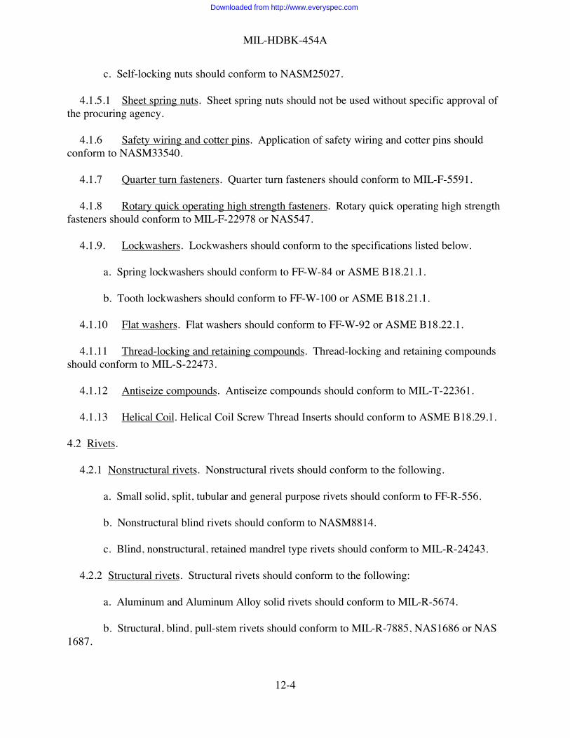
MIL-HDBK-454A
12-4
c. Self-locking nuts should conform to NASM25027.
4.1.5.1 Sheet spring nuts. Sheet spring nuts should not be used without specific approval ofthe procuring agency.
4.1.6 Safety wiring and cotter pins. Application of safety wiring and cotter pins shouldconform to NASM33540.
4.1.7 Quarter turn fasteners. Quarter turn fasteners should conform to MIL-F-5591.
4.1.8 Rotary quick operating high strength fasteners. Rotary quick operating high strengthfasteners should conform to MIL-F-22978 or NAS547.
4.1.9. Lockwashers. Lockwashers should conform to the specifications listed below.
a. Spring lockwashers should conform to FF-W-84 or ASME B18.21.1.
b. Tooth lockwashers should conform to FF-W-100 or ASME B18.21.1.
4.1.10 Flat washers. Flat washers should conform to FF-W-92 or ASME B18.22.1.
4.1.11 Thread-locking and retaining compounds. Thread-locking and retaining compoundsshould conform to MIL-S-22473.
4.1.12 Antiseize compounds. Antiseize compounds should conform to MIL-T-22361.
4.1.13 Helical Coil. Helical Coil Screw Thread Inserts should conform to ASME B18.29.1.
4.2 Rivets.
4.2.1 Nonstructural rivets. Nonstructural rivets should conform to the following.
a. Small solid, split, tubular and general purpose rivets should conform to FF-R-556.
b. Nonstructural blind rivets should conform to NASM8814.
c. Blind, nonstructural, retained mandrel type rivets should conform to MIL-R-24243.
4.2.2 Structural rivets. Structural rivets should conform to the following:
a. Aluminum and Aluminum Alloy solid rivets should conform to MIL-R-5674.
b. Structural, blind, pull-stem rivets should conform to MIL-R-7885, NAS1686 or NAS1687.
Downloaded from http://www.everyspec.com

MIL-HDBK-454A
12-5
c. Blind, drive type rivets should conform to MIL-R-27384.
5. Detail Guidelines
5.1 Threaded fasteners.
5.1.1Fastening of soft materials to soft materials. The mounting or assembly of parts made ofsoft materials to soft materials should be accomplished by one of the following methods:
a. A through-screw or bolt secured by a self-locking nut or plain nut with a lockwasher.
b. A through-screw or bolt secured by a plain nut with a thread locking compoundapplied to the threads of the screw or bolt and nut.
c. A screw or bolt in a threaded device such as a threaded bushing; a staked, clinched orpressed-in nut; or a threaded insert. The bushing, nut, or insert should be secured to, or should beinstalled in, the parent structure in accordance with the applicable procedures. The engagedlength of threaded inserts in the parent material should be at least 1.5 times the nominal diameterof the internal thread. Where the material thickness is insufficient to accommodate a 1.5 timesthread diameter insert, a shorter insert may be used in applications where maximum strength is notof primary importance; or a solid threaded bushing (which provides equal strength with less lengthbecause of the greater outside diameter of the bushing) should be used. When the screw or boltis to be installed in an aluminum alloy part, the aluminum alloy part should be provided withthreaded inserts of corrosion resistant steel or other suitable materials. When the screw or bolt isto be installed in a plastic material part, the plastic part should be provided with threaded inserts.If lockwashers or self-locking threaded inserts are not used, a thread-locking compound inaccordance with 4.1.10 should be applied to the threads of the screw or bolt.
d. A screw or bolt in a tapped hole, with a thread-locking compound in accordance with4.1.10 applied to the threads of the screw or bolt.
e. A stud in a tapped hole. Self-locking nuts should be avoided on stud-mountedcomponents, unless the stud material is compatible with the strength and material of the nut used.
5.1.2 Fastening of hard materials to soft materials. In addition to the methods outlined in5.1.1, a screw or bolt with a lockwasher may be used in a threaded bushing, staked, clinched orpressed-in nut, threaded insert or tapped hole.
5.1.3 Fastening of soft materials to hard materials. In addition to the methods outlined in5.1.1, a self-locking screw or bolt may be used in a hole tapped into the hard material.Self-locking screws or bolts with nonmetallic locking devices should not be used where thespecified service conditions or processing, such as baking of paints or soldering, might deterioratethe locking device.
Downloaded from http://www.everyspec.com

MIL-HDBK-454A
12-6
5.1.4 Fastening of hard materials to hard materials. Any of the methods outlined in 5.1.1through 5.1.3 may be used.
5.1.5 Fastening of brittle materials. Brittle castings or parts made of ceramic or other brittlematerials should be properly cushioned when necessary to prevent breakage. Washers or gasketsof suitable material and compressibility should be used between the facing surfaces of the brittlepart and other brittle or metal parts, when practicable, to prevent breakage or damage to theprotected parts during assembly or from severe shock, vibration or temperature changesencountered under the specified service conditions. Lead washers should not be used. Parts thatare secured with threaded devices and pliable washers should not use lockwashers as the lockingdevice, and other appropriate locking devices should be considered.
5.1.6Fastening with aluminum alloy or magnesium fasteners. The use of threaded fastenersmade of aluminumalloy or magnesium to mate with threaded parts of aluminum alloy or magnesium should beavoided wherever possible. Where such is required, an antiseize compound in accordance with4.1.11 should be used to prevent seizing of the threads.
5.1.7 Flat washers. Flat washers should be used for the following applications:
a. Between screw heads and soft materials, unless a washer head screw, or similar type thatprovides a bearing surface equivalent to the bearing surface of the appropriate flat washer, isbeing used.
b. Between a nut or lockwasher and a soft material.
c. Where lockwashers are used for securing a soft material, a flat washer should beprovided to prevent marring or chipping of the material or the applied protective coating, exceptin areas where an electrical ground is required.
d. Except where it conflicts with electromagnetic interference considerations, a flat washershould be used between an organically finished material and lock-washers, bolt and screw heads,or nuts.
5.1.8. Thread engagement. The length of the screws and bolts installed with nuts should besuch that the exposed portion is a minimum length equivalent to 1.5 thread pitches plus thechamber. Maximum length should be limited by the nearest larger standard screw length. Forhighly stressed applications, screws or bolts should have a minimum thread engagement of 1.5times their nominal diameter in tapped parts other than nuts. In normal applications, screws orbolts should have a minimum engagement length equal to their nominal diameter in tapped partsother than nuts. When the assembly is not frequently disassembled and where maximum strengthis not required, less thread engagement may be used.
5.2 Rivets. Rivets should be used in preference to other hardware for securing parts notrequiring removal. Wherever the thickness of metal which accepts the heads of flush rivets is less
Downloaded from http://www.everyspec.com

MIL-HDBK-454A
12-7
than the height of the rivet heads, the material should be dimpled rather than countersunk. Thedistance from the center of rivet holes to the edges of the material in which the rivets are placedshould not be less than 1.5 times the rivet diameter. Design and limitations of rivets should be inaccordance with MS33522 and MS33557. Rivets for joining magnesium parts should becomposition 5056 anodized aluminum alloy or an aluminum alloy having equal galvaniccompatibility with the magnesium being used.
5.3 Other fastening methods.
5.3.1Set screws. One set screw may be used on a flatted shaft. Two set screws at 90° to 120°displacement should be used when the shaft is not flatted. Cone-point set screws should not beused, except when the opposing metal has been properly countersunk to receive the cone-point.
5.3.2Access devices. Fasteners for use with access devices should be readily removable forreplacement purposes without damaging the attached panel or access door.
5.3.2.1 Nonstructural applications. Quarter-turn fasteners should be used only to retainnonstructural access to devices where quick access is required.
5.3.2.2 Structural applications. Rotary, quick-operating, high strength panel fasteners shouldbe used to retain structural access devices where quick access is required.
5.3.2.3 Threaded fasteners. Threaded fasteners used with access devicesshould be self-aligning, captive type hardware.
5.3.3Screw threaded device applications.
5.3.3.1 Screws or bolts without nuts. Applications requiring the use of screws or boltswithout nuts should use one of the following screw locking methods:
a. Lockwashers under the heads of the screws or bolts
b. Self-locking screws
c. Self-locking threaded inserts
d. A locking or retaining compound in accordance with 4.1.10 applied to the threads
e. Safety wire through drilled heads in accordance with 4.1.5.
5.3.3.2 Countersunk head screws. Countersunk head screws, when not secured by otherlocking means, should be secured by the application of a thread-locking compound in accordancewith 4.1.10. Staking by means of upsetting metal is acceptable for permanent assemblies whenother means are impracticable or unsatisfactory for design reasons.
Downloaded from http://www.everyspec.com
MIL-HDBK-454A
12-8
5.3.3.3 Thread-forming, thread-cutting, and drive screws. Thread forming, thread-cutting,and drive screws should not be used except for attaching identification plates.
5..3.3.4 Safety wiring and cotter pins. Safety wiring and cotter pins should not be used onterminals such as screws and threaded studs that are required to function as electrical terminals.
5.3.3.5 Thread-locking and retaining compounds. Thread-locking and retaining compoundsshould not be used where required electrical conductivity is impaired or failure of the compoundwould endanger personnel or damage the equipment.
Downloaded from http://www.everyspec.com

MIL-HDBK-454A
13-1
GUIDELINE 13
STRUCTURAL WELDING
1. Purpose. This guideline establishes criteria for structural welds. Welded electrical connectionsare excluded from this guideline.
2. Applicable Documents.
MIL-STD-22 Welded Joint DesignMIL-HDBK-5 Metallic Materials and Elements for Aerospace Vehicle StructuresMIL-HDBK-730 Materials JoiningAMS-STD-1595 Qualification of Aircraft, Missile and Aerospace Fusion WeldersANSI/AWS A2.4 Standard Symbols for Welding, Brazing and Nondestructive
ExaminationANSI/AWS A3.0 Standard Welding Terms and Definitions, Including Terms for
Brazing, Soldering, Thermal Spraying and Thermal CuttingAWS D1.1 Structural Welding Code-SteelSAE/AMS 2680 Welding, Electron Beam, for Fatigue Critical ApplicationSAE/AMS 2681 Electron-Beam WeldingSAE/AMS-W-6858 Welding, Resistance, Spot and SeamSAE/AMS-STD-2219 Fusion Welding for Aerospace Applications
3. Definitions. Not applicable.
4. General Guidelines.
4.1 Arc and gas welding. Welding by arc and gas methods should be performed by operatorswho have passed the applicable certification tests and have a certificate of proficiency inaccordance with AMS-STD-1595. Welding of aluminum, magnesium, and steel alloys shouldconform to SAE/AMS-STD-2219.
4.2 Resistance welding. Resistance welding of joints should conform to SAE/AMS-W-6858.
5. Detail Guidelines
5.1 Welding. The joint areas of all parts to be welded should be cleaned of contaminants andmaterials which may be detrimental to obtaining satisfactory welds. Degradation of materialproperties in the heat affected zone caused by welding should be considered. Weldments shouldbe stress relieved when induced stress resulting from welding, design configuration, or materialswelded may be harmful. See ANSI/AWS 2.4 for welding symbols, ANSI/AWS A3.0 for weldingterms and definitions, and MIL-STD-22 for welded joint designs. MIL-HDBK-730 providesguidance in this field of materials joining and its related processes.
Downloaded from http://www.everyspec.com

MIL-HDBK-454A
13-2
5.2 Resistance welding. MIL-HDBK-5 may be used as a guide for spot-to-sheet edgedistances and allowable strengths.
5.3 Noncritical applications. In ground equipment applications, welding procedures inaccordance with MIL-STD-1261 may be used where, if the weld should fail, it will notcompromise personnel or equipment safety or prevent completion of the mission.
5.4 Other methods. Other welding methods, such as the electron beam process of AMS 2680and AMS 2681, may be used provided approval is obtained from the procuring activity.
Downloaded from http://www.everyspec.com

MIL-HDBK-454A
14-1
GUIDELINE 14
TRANSFORMERS, INDUCTORS, AND COILS
1. Purpose. This guideline establishes criteria for the selection and application of transformers,inductors, and coils.
2. Applicable Documents:
MIL-T-55631 Transformers, Intermediate Frequency, Radio Frequency andDiscriminator, General Specification for
MIL-T-83721 Transformer, Variable, Power, General Specification forMIL-STD-981 Design, Manufacturing and Quality Standards for Custom
Electromagnetic Devices for Space Applications
3. Definitions. Not applicable.
4. General Guidelines.
4.1 Selection. Selection of transformers, inductors, and coils should be in accordance withthe following sections.
4.1.1 Intermediate, radio frequency and discriminator transformers. Intermediate, radiofrequency and discriminator transformers should conform to Grade 1, 2, or 4 of MIL-T-55631.The use of Grade 3 transformers should be limited to hermetically sealed or encapsulatedassemblies.
4.1.2 Variable transformers. Variable transformers should conform to MIL-T-83721.
4.1.3 Custom electromagnetic devices for space applications. Custom electromagneticdevices for space applications should conform to MIL-STD-981.
5. Detail Guidelines. Not applicable.
Downloaded from http://www.everyspec.com

MIL-HDBK-454A
15-1
GUIDELINE 15
METALS, CORROSION RESISTANCE
1. Purpose. This guideline establishes criteria for the selection and treatment of metals as relatedto their ability to resist corrosion.
2. Applicable Documents.
MIL-STD-889 Dissimilar Metals
3. Definitions. Not applicable.
4. General Guidelines.
4.1 Corrosion Resistant. Metals should be corrosion resistant or should be coated ormetallurgically processed to resist corrosion.
4.2 Metallic Parts. Materials and processes for metallic parts should conform to applicablerequirements in MIL-STD-889.
5. Detail Guidelines.
5.1 Selection of Metals. The environmental severity to which the equipment will be exposedshould be considered in selection of metals.
5.2 Noncorrosion Resistant. The use of noncorrosion resistant steel alloys, except wherespecifically required for electronic purposes, should be kept to a minimum.
Downloaded from http://www.everyspec.com

MIL-HDBK-454A
16-1
GUIDELINE 16
DISSIMILAR METALS
1. Purpose. This guideline establishes criteria for the selection and protection of dissimilar metalcombinations and other significant corrosion behavior factors.
2. Applicable Document.
MIL-STD-889 Dissimilar Metals
3. Definitions. Not applicable.
4. General Guidelines.
4.1 Selection of metals. Selection of metals for use in electronic equipment should be made inaccordance with the requirements of MIL-STD-889.
5. Detail Guidelines.
5.1 Incompatible Metal. Where electronic design requirements preclude the insulation ofincompatible metal combinations as identified in MIL-STD-889 from one another, specificattention should be paid to isolating the combination from exterior environments.
Downloaded from http://www.everyspec.com

MIL-HDBK-454A
17-1
GUIDELINE 17
PRINTED WIRING
1. Purpose. This guideline established criteria for the design and treatment of printed wiringassemblies.
2. Applicable Documents.
MIL-HDBK-1861 Electrical and Electronic Assemblies, Boards, Cards, andAssociated Hardware, Selection and Use of
ANSI/IPC-D-322 Guidelines for Selecting Printed Wiring Board Sizes UsingStandard Panel Sizes
3. Definitions. Not applicable.
4. General Guidelines.
4.1 Rigid printed wiring and printed wiring boards. Rigid printed wiring and printed wiringboards for single-sided, double-sided, and multilayer printed wiring should conform toMIL-HDBK-1861. The materials used for single-sided, double-sided, and multilayer printedwiring boards should conform to MIL-HDBK-1861.
4.2 Rigid printed wiring assemblies. Rigid printed wiring assemblies consisting of rigidprinted wiring boards on which separately manufactured parts have been added should conform toMIL-HDBK-1861.
4.3 Conformal coating. When conformal coating is required, rigid printing wiring assembliesshould be conformally coated with a coating material which conforms to MIL-HDBK-1861.
4.4 Flexible and rigid flex wiring. Flexible and rigid-flex printed wiring should conform toMIL-HDBK-1861 and should be designed in accordance with MIL-HDBK-1861.
4.5 Discrete wiring boards. Discrete wiring boards with plated-through holes should be inaccordance with MIL-HDBK-1861.
4.6 Backplane assemblies, printed wiring. Electrical backplane printed wiring assembliesshould conform to MIL-STD-1861 and should be designed in accordance with MIL-STD-1861.
5. Detail Guidelines.
5.1 Printed wiring board size. Guidelines for the selection of printed wiring board sizes aredelineated in ANSI/IPC-D-322.
Downloaded from http://www.everyspec.com

MIL-HDBK-454A
18-1
GUIDELINE 18
DERATING OF ELECTRONIC PARTS AND MATERIALS
1. Purpose. This guideline establishes criteria for derating of electronic parts and materials.
2. Applicable Document .
MIL-HDBK-1547 Electronic Parts, Materials, and Processes for Space and LaunchVehicles
3. Definitions. Not applicable.
4. General Guidelines.
4.1 Derating. In the application of electronic parts and materials, the parts and materialsselected should be used within their electrical ratings and environmental capabilities; (e.g., anyambient or hot spot temperatures, voltage, current, or power dissipation). Derating should beaccomplished as necessary to assure the required equipment reliability within the specifiedoperating conditions.
4.2 Derating for launch vehicles and space systems. Electronic parts and materials used inlaunch vehicles or space systems should be derated in accordance with the guidelines ofMIL-HDBK-1547.
5. Detail Guidelines. Not applicable.
Downloaded from http://www.everyspec.com

MIL-HDBK-454A
19-1
GUIDELINE 19
TERMINATIONS
1. Purpose. This guideline establishes criteria for the selection and application ofterminations.
2. Applicable Documents .
MIL-T-15659 Terminal, Lug, Solder, Copper and Phosphor BronzeMIL-T-55156 Terminals, Lug, Splices, Conductor; Screw Type, General
Specification forMIL-HDBK-1277 Splices, Terminals, Terminal Boards, Binding Posts, Terminal
Junction Systems, Wire Caps; ElectricalA-A-59125 Terminal Boards, Molded, Barrier Screw and Stud Types And
Associated AccessoriesSAE/AS7928 Terminals, Lug: Splices, Conductors: Crimp-Style, CopperSAE/AS27212 Terminal Boards Assembly, Molded-in Stud, Electric
3. Definitions. Not applicable.
4. General Guidelines.
4.1 Terminals. Lug terminals, stud terminals, feed-through terminals and bindingposts should be selected from MIL-HDBK-1277.
4.1.1 Lug terminals. Lug terminals should conform to one of the followingspecifications.
MIL-T-7928 Crimp, Insulated and NoninsulatedMIL-T-15659 SolderMIL-T-55156 Screw
4.1.2 Number of wires per terminal or lug. The number of wires terminated in anindividual terminal or lug should not be greater than three. Multisection turret, bifurcated,or multi-hole lug terminals should have not more than three wires per section, tong, orhole. In no case should the total cross sectional area of the terminated wires exceed thecross sectional area capacity of the terminal or lug. If a greater number of wires arerequired than those specified herein, approval of the procuring activity should be obtained.
4.2 Terminal boards. Terminal boards should be selected from MIL-HDBK-1277.
4.2.1 Number of lugs per terminal. The maximum number of lugs to be connected toany one terminal on a terminal board should be two for screw-type terminal boardscovered by A-A-59125 and as specified in the detail specification sheets for stud-type
Downloaded from http://www.everyspec.com

MIL-HDBK-454A
19-2
terminal boards. Not more than four lugs should be connected to any one terminal of aboard covered by AS27212. Accessories such as stud connectors, straddle plates, jumpersand terminal board lugs should be counted as lugs for this purpose.
4.3 Terminal junction systems. Terminal junction systems should be selected fromMIL-HDBK-1277.
5. Detail Guidelines.
5.1 Crimping. Crimping of terminal lugs should be so accomplished that theconnections will meet the resistance (voltage drop) and tensile strength requirements andtests of MIL-T-7928.
Downloaded from http://www.everyspec.com

MIL-HDBK-454A
20-1
GUIDELINE 20
WIRE, HOOKUP, INTERNAL
1. Purpose. This guideline establishes criteria for the selection and application of electricalinternal hookup wire.
2 Applicable Documents .
QQ-W-343 Wire, Electrical, Copper (Uninsulated)MIL-W-16878 Wire, Electrical, Insulated, General Specification forMIL-W-22759 Wire, Electrical, Fluoropolymer-Insulated, Copper or Copper AlloyMIL-W-81044 Wire, Electric, Crosslinked Polyalkene, Crosslinked Alkane-Imide
Polymer, or Polyarylene Insulated, Copper or Copper AlloyMIL-DTL-81381 Wire, Electric, Polyimide Insulated, Copper or Copper AlloyMIL-W-81822 Wire, Electrical, Solderless Wrap, Insulated and Uninsulated, General
Specification forMIL-STD-681 Identification Coding and Application of Hook-Up and Lead WireASTM B298 Silver-Coated Soft or Annealed Copper Wire
3. Definitions. Not applicable.
4. General Guidelines.
4.1 Selection. Internal hookup wire should be selected from the types and classes specifiedby the documents listed in table 20-I. For solderless wrap applications, wires should be selectedwhich are in accordance with MIL-W-81822.
4.1.1 MIL-W-16878 usage. MIL-W-16878 should not be used for Air Force or Navyaerospace applications.
4.1.2 MIL-W-22759 usage. MIL-W-22759 wire with only single polytetrafluoroethyleneinsulation used in Air Force space and missile applications should require the approval of theprocuring activity.
4.1.3 Insulation restriction. Wires with polyvinyl chloride insulation should not be used inaerospace applications. Use of these wires in any other application requires prior approval of theprocuring activity.
4.1.4 Silver plated copper wire. Silver plated copper wire should not be used inapplications involving Army missile systems without certification by the wire manufacturer that itpasses the sodium polysulfide test in accordance with ASTM B298. Silver plated copper wireshould not be used in conjunction with water-soluble solder fluxes. Wire should be stored andhandled in such a way so as to minimize exposure to moisture.
Downloaded from http://www.everyspec.com

MIL-HDBK-454A
20-2
4.2 Identification. Hookup wires in the equipment should be, insofar as practicable,distinctly coded in color or numbered. Short hookup wire, 150 mm or less between terminationpoints, need not be marked if the path of the short wire can be easily and visually traced. Theunmarked wire must be specified on the drawing. Codes, when used, should be in accordancewith MIL-STD-681 or as otherwise agreed upon with the procuring activity. Numbers should notbe used where they would be difficult to read or trace, such as in compact assemblies.
4.3 Bare wire. Bare hookup wire should be type H class S, soft or drawn and annealed, andcoated, and should conform to QQ-W-343. Bare hookup wire should not be used unlessinsulated wire is impractical because of circuit characteristics or shortness of wire run.
5. Detail Guidelines.
5.1 Solid or stranded. Stranded wire should be used for conductors and cables which arenormally flexed in use and servicing of the equipment, such as cables attached to the movable halfof detachable connectors and hanging cables attached to removable or movable doors and shields.Leads 150 mm or less in length may be run as solid wires unless they form interconnectionsbetween shock isolation mounted parts and non-shock isolation mounted parts. There are someother instances, such as wire wrapping, where a solid conductor may be required regardless oflength.
5.2 Cold flow. Certain insulating materials exhibit a cold flow characteristic. Cautionshould be used in the selection of these materials in applications requiring restrictive clamping ortying, etc., where this feature may result in exposed or shorted conductors.
5.3 Stranded copper conductor test. The following test procedure should be used forstranded conductors since the ASTM B298 procedure covers only a single, round conductor.
5.3.1 Sodium polysulfide test. Stranded samples of annealed copper or copper alloyconductors should be tested per ASTM B298. When this test is performed one factor whichshould be taken in to consideration is that the ASTM test applies to single end wires taken beforestranding. Thus the applicability of the polysulfide test is restricted by the ASTM in recognitionof the abrasion to the wire inherent in the stranding process. As a result the following exceptionsand criteria apply when testing stranded product:
a. Examination of the samples to occur immediately after the solution cycle.
Downloaded from http://www.everyspec.com

MIL-HDBK-454A
20-3
b. Samples to be immersed into the solution in the as-stranded condition.
(1) Unilay constructions to be tested as the whole conductor.
(2) Concentric constructions to be tested as whole conductor.
(3) Two members from each layer of rope constructions to be tested after they havebeen carefully removed from the finished rope.
Downloaded from http://www.everyspec.com

MIL
-HD
BK-4
54A
20-4
TABL
E 20
-I. W
ire, e
lect
rical
Cons
truct
ion
Max
Spec
type
1/2/
Insu
latio
nCo
ndM
axSp
ecor
Mat
er-
Cond
ucto
rPr
imar
yJa
cket
tem
prm
sno
Title
clas
sia
lCo
atin
gTy
pePr
imar
yco
ver
topc
oat
°Cvo
ltsRe
mar
ks
M50
86/1
8 M
5086
/2Cu
/ASn
8, 1
110
560
0
M50
86/4
8 M
5086
/5 M
5086
/6H
SAA
g9A
110
MIL
-W-5
086
Wire
, Ele
ctric
, P
olyv
inyl
Chl
orid
e I
nsul
ated
, Cop
per
or C
oppe
r Allo
y
M50
86/7
Cu/A
Sn
Str
1
810
5
3000
600
M16
878/
160
0M
1687
8/2
1000
M16
878/
3A
g, S
n1
8,10
,11
1,8,
10,1
110
530
00M
1687
8/4
600
M16
878/
510
00M
1687
8/6
Cu/A
,H
SA,
CC
W3A
3A,3
B,4A
,13
B 3/
250
M16
878/
760
0M
1687
8/8
64A
,8,1
0,11
200
1000
M16
878/
10
Ag
Sn2A
8,10
,11
4A,8
,10,
1175
M16
878/
1160
0
M16
878/
1210
00M
1687
8/13
Cu/A
Cu/A
,C
CW
Ag
4A4A
200
250
M16
878/
14A
g,Sn
600
M16
878/
1510
00M
1687
8/16
Cu/A
Sn2C
125
600
M16
878/
1730
00M
1687
8/18
1000
M16
878/
19A
g, S
n1
810
530
00M
1687
8/20
250
M16
878/
2160
0M
1687
8/22
Ag
3B20
010
00M
1687
8/23
3A25
0M
1687
8/24
3B
MIL
-W-1
6878
Wire
, Ele
ctric
al,
Insu
late
d
M16
878/
25
Cu/A
HSA
CC
WN
i
S,St
r
3A3A
, 3B,
4A
13B3
/26
060
0
See
Not
e 4
Downloaded from http://www.everyspec.com
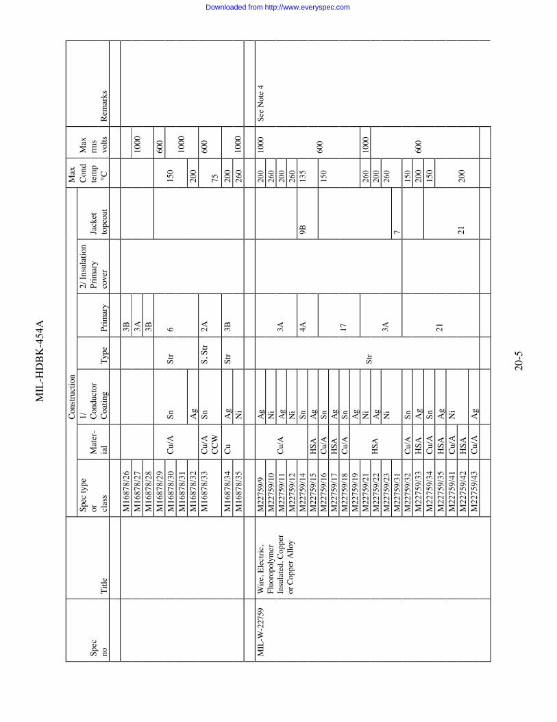
MIL
-HD
BK-4
54A
20-5
Cons
truct
ion
Max
Spec
type
1/2/
Insu
latio
nCo
ndM
axSp
ecor
Mat
er-
Cond
ucto
rPr
imar
yJa
cket
tem
prm
sno
Title
clas
sia
lCo
atin
gTy
pePr
imar
yco
ver
topc
oat
°Cvo
ltsRe
mar
ks
M16
878/
263B
M16
878/
273A
M16
878/
283B
1000
M16
878/
2960
0M
1687
8/30
M16
878/
31Sn
150
M16
878/
32
Cu/A
Ag
Str
6
200
1000
M16
878/
33Cu
/AC
CW
SnS,
Str
2A75
600
M16
878/
34A
g20
0M
1687
8/35
Cu
Ni
Str
3B26
010
00
M22
759/
9A
g20
0M
2275
9/10
Ni
260
M22
759/
11A
g20
0M
2275
9/12
Ni
3A26
0M
2275
9/14
Cu/A
SnM
2275
9/15
HSA
Ag
4A9B
135
M22
759/
16Cu
/ASn
M22
759/
17H
SAA
gM
2275
9/18
Cu/A
SnM
2275
9/19
Ag
17
150
1000
600
M22
759/
21N
i26
010
00M
2275
9/22
Ag
200
M22
759/
23M
2275
9/31
HSA
Ni
3A7
260
M22
759/
32Cu
/ASn
150
M22
759/
33H
SAA
g20
0M
2275
9/34
Cu/A
Sn15
0M
2275
9/35
HSA
Ag
M22
759/
41Cu
/AM
2275
9/42
HSA
Ni
M22
759/
43Cu
/AA
g
Str
21
2120
0
600
See
Not
e 4
MIL
-W-2
2759
Wire
, Ele
ctric
,Fl
uoro
poly
mer
Insu
late
d, C
oppe
ror
Cop
per A
lloy
Downloaded from http://www.everyspec.com

MIL
-HD
BK-4
54A
20-6
Cons
truct
ion
Max
Spec
type
1/2/
Insu
latio
nCo
ndM
axSp
ecor
Mat
er-
Cond
ucto
rPr
imar
yJa
cket
tem
prm
sno
Title
clas
sia
lCo
atin
gTy
pePr
imar
yco
ver
topc
oat
°Cvo
ltsRe
mar
ks
M81
044/
12Cu
/ASn
MIL
-W-8
1044
Wire
, Ele
ctric
,Cr
ossli
nked
Pol
y-al
kene
, etc
.In
sula
ted
M81
044/
13H
SAA
gSt
r2B
9B15
060
0Se
e ap
plic
atio
nte
mp
limita
tion
on d
etai
l spe
csh
eet
M81
381/
7A
gM
8138
1/8
Cu/A
Ni
M81
381/
9A
gM
8138
1/10
HSA
Ni
4B
M81
381/
11A
gM
8138
1/12
Cu/A
Ni
M81
381/
13A
gM
8138
1/14
HSA
Ni
M81
381/
17A
gM
8138
1/18
Cu/A
Ni
M81
381/
19A
gM
8138
1/20
HSA
Ni
200
M81
381/
21
MIL
-DTL
-81
381
Wire
, Ele
ctric
,Po
lym
ide
Insu
late
d, C
oppe
ror
Cop
per A
lloy
M81
381/
22Cu
/ASn
Str
19
20
150
600
/11/
12, a
nd /2
2ha
ve a
brig
htar
omat
ic p
oly-
amid
e br
aid
with
clea
r fin
isher
coat
ings
on
8 A
WG
and
larg
er
Downloaded from http://www.everyspec.com

MIL
-HD
BK-4
54A
20-7
TABL
E 20
-I. W
ire, e
lect
rical
- Co
ntin
ued.
Insu
latio
n
1/
Cond
ucto
r Cod
e
Des
crip
tion
2/
Co
de
Des
crip
tion
Mat
eria
l Cu/
ACo
pper
, ann
eale
d
1Po
lyvi
nyl c
hlor
ide/
extru
ded
C
u/H
Copp
er, h
ard
draw
n
2A
Poly
ethy
lene
/ext
rude
d
CC
WCo
pper
, cov
ered
stee
l
2
BPo
lyal
kene
/cro
ss-li
nked
/ext
rude
d
HA
SH
igh
stren
gth
copp
er
2C
Poly
ethy
lene
/cro
ss-li
nked
/mod
ified
/ext
rude
d
a
lloy
3A
Poly
tetra
fluor
oeth
ylen
e/ex
trude
d (T
FE te
flon)
A
1
A
lum
inum
3B
Poly
tetra
fluor
oeth
ylen
e/ta
pe
C
oatin
g S
n Ti
n
3
CPo
lyte
traflu
oroe
thyl
ene/
min
eral
fille
d/ex
trude
d
Ag
Silv
er
4A
Fluo
rinat
ed e
thyl
ene
prop
ylen
e/ex
trude
d
Ni
Nic
kel
(FE
P te
flon)
4B
Fluo
rinat
ed e
thyl
ene
prop
ylen
e/di
sper
sion
6
Silic
one
rubb
er/e
xtru
ded
Typ
e
S
Solid
7Po
lyim
ide
lacq
uer (
Pure
ML)
Str
Stra
nded
8Po
lyam
ide/
extru
ded
(Nyl
on)
9A
Poly
viny
liden
e flu
orid
e/ex
trude
d (K
ynar
)
9
BPo
lyvi
nylid
ene
fluor
ide/
extru
ded/
cros
s-lin
ked
3/
Whe
n sp
ecifi
ed o
n pu
rcha
se o
rder
1
0Br
aid/
synt
hetic
yar
n/la
cque
r im
preg
nate
d
1
1Br
aid/
nylo
n/im
preg
nate
d
4/
V
ario
us c
ombi
natio
ns o
f prim
ary,
prim
ary
13
ABr
aid/
glas
s fib
er/im
preg
nate
d
c
over
, and
jack
et in
sula
tions
, and
uns
hiel
ded,
1
3BBr
aid/
TFE
coat
ed g
lass
fibe
r/TFE
fini
sh
s
hiel
ded,
etc
., co
nstru
ctio
ns a
re a
vaila
ble
1
7ET
FE f
luor
opol
ymer
to
mee
t app
licat
ion
requ
irem
ents.
See
det
ail
1
9Fl
uoro
carb
on/p
olyi
mid
e ta
pe
w
ire sp
ecifi
catio
n.
20
Mod
ified
aro
mat
ic p
olyi
mid
e re
sin
2
1Et
hyle
ne-te
traflu
oroe
thyl
ene/
cros
s-lin
ked/
m
odifi
ed/e
xtru
ded
Downloaded from http://www.everyspec.com

MIL-HDBK-454A
21-1
GUIDELINE 21
CASTINGS
1. Purpose. This guideline establishes criteria for the design, classification, inspection, and repairof castings.
2. Applicable Documents .
MIL-STD-276 Impregnation of Porous Metal Castings And Powdered Metal ComponentsSAE/AMS-STD-2175 Castings, Classification and Inspection of
3. Definitions. Not applicable.
4. General Guidelines.
4.1 Die castings. Die castings should not be used where the casting might be subject to impact.Zinc alloy die castings should not be used where dimensional changes of the casting could affectuse of equipment.
4.2 Porous castings. When required, castings should be impregnated in accordance withMIL-STD-276.
4.3 Classification and inspection. Castings should be classified and inspected in accordancewith SAE/AMS-STD-2175.
4.4 Inserts. Inserts which are intended to be cast in place should be knurled, grooved, orotherwise prepared to secure satisfactory keying of the insert to the casting. Inserts should befabricated from a material which is not adversely affected by exposure to the molten casting alloy.When inserts are located near a casting edge, sufficient edge distance should be allowed in orderto develop the required resistance to insert pull-out, and to avoid cracking of the casting. Castingdefects resulting from use of inserts, such as partial alloying, poor bonds, porosity, and cracksshould not be present.
5. Detail Guidelines.
5.1 Selection and application. In any design utilizing metallic castings, consideration should begiven to intended application, the availability of molding and casting alloys, the choice of asuitable casting process (see table 21-I), and the use of ribs and fins.
Downloaded from http://www.everyspec.com

MIL-HDBK-454A
21-2
TABLE 21-I. General comparison of metallic casting processes.
SuitabilityDimen- Ability to Suitability Surface for large
Type of sional reproduce Tool for volume smooth- sizedcastings accuracy fine detail cost production ness castings
Sand 3 3 1 3 3 1Die 1 1 3 1 1 3Investment 1 1 3 2 1 3Shellmold 2 2 3 1 2 3Permanentmold 2 2 3 1 2 2Plastermold 2 1 1 3 2 3
Legend: 1 = Very good; 2 = good; 3 = fair
5.2 Repair of unmachined castings. Repair of minor discontinuities or defects in unmachined orraw castings should be permitted only when specific approval has been granted by the contractorMaterial Review Board (MRB), or is specified on the engineering documentation. Weld repairshould be limited to Class 3 and Class 4 castings (Class 1 and Class 2 repair should requireprocuring activity approval) and to areas where no severe stress will be encountered. Heattreatable alloys must be fully reheat treated after welding to meet drawing guidelines.
5.3 Repair of machined castings. Repair of defects in machined castings should be permittedfor Class 3 and Class 4 castings based on the contractor's MRB decision. Class 1 and Class 2casting repair should require procuring activity approval. Reheat treatment should be requiredunless engineering analysis during MRB action can demonstrate it is unnecessary.
Downloaded from http://www.everyspec.com

MIL-HDBK-454A
22-1
GUIDELINE 22
PARTS MANAGEMENT
1. Purpose. This guideline offers guidance as to parts management and selection which may beconsidered when preparing contractual documents. Parts management and selection should bedirectly specified in the contract or the system/equipment specification, as appropriate.
2. Applicable Documents.
MIL-HDBK-965 Acquisition Practice for Parts Management
ANSI/AIAA R-100 Recommended Practice for Parts Management
3. Definitions. Not applicable.
4. General Guidelines. Not applicable.
5. Detail Guidelines.
5.1 Parts Management Program. MIL-HDBK-965 establishes four procedures covering thesubmission, review, and approval of Program Parts Selection Lists and changes thereto. Theobjective is to achieve life cycle cost savings and cost avoidance’s by:
a. assisting equipment or system managers and their contractors in the selection of partscommensurate with contractual requirements
b. minimizing the variety of parts used in new designc. enhancing interchangeability, reliability, and maintainability of military equipment and
suppliesd. conserving resourcese. assuring long term availability of parts. MIL-HDBK-965 should be tailored when
applied; application guidance is offered in the document
5.2 Parts Management Program for Spacecraft and Launch Vehicles. (Not applicable toNASA programs.) R-100-AIA establishes the criteria and guidelines for the preparation andimplementation of a Parts, Materials, and Processes Standardization Control and ManagementProgram for use during the design, development, fabrication, and test of spacecraft and launchvehicles. The implementation of this handbook is intended to:
a. assure total, integrated, and coordinated management of the selection, application,procurement, and standardization of parts, materials and processes (PMP)
b. reduce program costsc. improve the standardization and reliability of program parts, materials, and processesd. assure long term availability of parts
Downloaded from http://www.everyspec.com

MIL-HDBK-454A
23-1
GUIDELINE 23
ADHESIVES
1. Purpose. This guideline establishes guidance for the selection and application of adhesives.
2. Applicable Documents.
MMM-A-121 Adhesive, Bonding, Vulcanized Synthetic Rubber to SteelMMM-A-132 Adhesive, Heat Resistant, Airframe Structural, Metal to MetalMMM-A-134 Adhesive, Epoxy Resin, Metal to Metal Structural BondingMMM-A-138 Adhesive, Metal to Wood, StructuralMMM-A-181 Adhesive, Phenol, Resorcinol, or Melamine BaseMMM-A-189 Adhesive, Synthetic-Rubber, Thermoplastic, General PurposeMMM-A-1617 Adhesive, Rubber Base, General PurposeMMM-A-1931 Adhesive, Epoxy, Silver Filled, ConductiveMIL-A-3920 Adhesive, Optical, ThermosettingMIL-A-22397 Adhesive, Phenol and Resorcinol Resin Base (for Marine Service Use)MIL-A-24179 Adhesive, Flexible Unicellular-Plastic Thermal InsulationMIL-A-46146 Adhesive-Sealants, Silicone, RTV, Non-Corrosive (for Use With
Sensitive Metals and Equipment)MIL-HDBK-691 Adhesive Bonding29 CFR 1910 Code of Federal Regulations, Title 29, Chapter XVII, Part 1910A-A-1936 Adhesive, Contact, Neoprene RubberA-A-3097 Adhesive, Cyanoacrylate, Rapid Room-Temperature Curing,
SolventlessSAE/AMS-A-8576 Adhesive, Acrylic Base, for Acrylic PlasticSAE/AMS-A-25463 Adhesive, Film Form, Metallic Structural Sandwich Construction
3. Definitions.
3.1 Adhesives. Adhesives are substances capable of holding materials together by surfaceattachment. Adhesive is a general term and includes, among others, cement, glue, mucilage andpaste. All of these terms are loosely used interchangeably.
4. General Guidelines. Not applicable.
5. Detail Guidelines.
5.1 Design of joint. The joint should be designed to minimize concentrations of stress. Thebasic stress should be in shear. The weakest design is where the basic stress is in cleavage or peeland nonaxial loading in tension produces cleavage.
5.2 Deleterious effects. The user should ascertain that the formulation of the adhesiveselected will have no deleterious effects on the bonded assembly or nearby items when the bonded
Downloaded from http://www.everyspec.com

MIL-HDBK-454A
23-2
assembly is in storage, transit or use under the environmental conditions for which it wasdesigned. Deleterious effects may be caused by the slow release of trapped solvents which candamage many types of rubber and plastic, or cause other harmful results degrading operation ofthe equipment.
5.3 Application. Care should be taken to avoid starved joints which are the result of eitherabsorption of adhesive by a porous material, poor application, inadequate coverage, or excessivepressure. Where one or both of the adherents are porous, successive thin coats of adhesiveshould be applied to completely seal the surface, and each coat should be dry before the next coatis applied. This procedure should be used instead of the application of one thick adhesive coat tothe porous surface, except in the case of silicone adhesives. In general, the thicker the adhesivelayer, the lower the shear resistance, but the higher the strength to impact and peeling.
5.4 Structural compatibility. Adhesives which are not compatible structurally should beavoided. For example, a brittle adhesive should not be used for glass bonding because excessiveshrinkage during setting or curing will load the glass in tension. For assemblies which may beflexed or subject to impact, a brittle adhesive should not be used.
5.5 Carcinogens. Certain chemicals have been identified in the Occupational Safety andHealth Act (OSHA) as cancer producing substances (carcinogens). Before using any materialswhich might contain carcinogens, they should be evaluated in accordance with 29 CFR 1910.Consideration of the toxicity of a substance should be given prior to material selection.
5.6 Thermoplastic. All thermoplastic adhesives have a tendency to creep under load,especially at elevated temperature, and should not be used in critical structural applications.Many thermoplastic adhesives have limited or poor resistance to certain solvents.
5.7 Materials to be bonded. The materials to be bonded assume critical importance as thereare some materials, such as fluorocarbon, polyethylene, and nylon that cannot be bondedsatisfactorily without prior treatment, special adhesives, or both.
5.8 Guide for selection and application. The following, although not a complete list, may beused as a guide in selecting adhesives and bonding procedures to meet design guidelines inelectronic equipment.
Downloaded from http://www.everyspec.com

MIL-HDBK-454A
23-3
MMM-A-121 MMM-A-1931 A-A-3097MMM-A-132 MIL-A-3920 SAE/AMS-A-8576MMM-A-134 MIL-A-22397 SAE/AMS-A-25463MMM-A-138 MIL-A-24179MMM-A-181 MIL-A-46146MMM-A-189 MIL-HDBK-691MMM-A-1617 A-A-1936
Many of these specifications have no requirements pertaining to electrical properties. Whereelectrical properties are important, the suitability of the material for the application should beestablished.
Downloaded from http://www.everyspec.com

MIL-HDBK-454A
24-1
GUIDELINE 24
WELDS, RESISTANCE, ELECTRICAL INTERCONNECTIONS
1. Purpose. This guideline establishes criteria for resistance welds of electrical andelectronic interconnections and part leads. This guideline does not include structural welds.
2. Applicable Documents. Not applicable.
3. Definitions. Not applicable.
4. General Guidelines.Not applicable.
5. Detail Guidelines.
5.1 Contaminants. All surfaces of leads or parts to be welded should be free of contaminantswhich would adversely affect forming of the welded joint.
5.2 Electrical connections. Except where needed to meet electromagnetic interference orsystem compatibility guidelines, welded electrical connections should not be used where it may benecessary to disconnect, replace, or reconnect a part or module during servicing.
5.3 Excess conductor wire. Excess conductor wire should be trimmed sufficiently close toprovide adequate clearance to prevent possible electrical shorting but not so close as to causedamage to the welded joint.
5.4 Strain relief. Each part lead terminating at a connection point should have allowance forstrain relief to minimize tensile or shear stress.
Downloaded from http://www.everyspec.com

MIL-HDBK-454A
25-1
GUIDELINE 25
ELECTRICAL POWER
1. Purpose. This guideline establishes criteria for electrical power.
2. Applicable Documents.
MIL-STD-704 Aircraft Electric Power Characteristics MIL-STD-1275 Characteristics of 28 Volt DC Electrical Systems in Military
Vehicles MIL-STD-1399 Interface Standard for Shipboard Systems
MIL-HDBK-411 Power and Environment for Sensitive DoD Electronic Equipment
3. Definitions. Not applicable.
4. General Guidelines.
4.1 Airborne. The electrical power guidelines for airborne and associated equipment shouldbe in accordance with MIL-STD-704.
4.2 Shipboard. The electrical power guidelines for shipboard and associated equipment shouldbe in accordance with type I or type II of section 300 of MIL-STD-1399.
4.3 Ground vehicles. The electrical power guidelines for military ground vehicles should be inaccordance with MIL-STD-1275.
5. Detail Guidelines.
5.1 Critical fixed communications and related automatic data processing facilities. MIL-HDBK-411 provides the electrical power guidelines for critical communications and relatedautomatic data processing equipment and should be for a nominal -48 V dc uninterruptible powersupply.
Downloaded from http://www.everyspec.com

MIL-HDBK-454A
26-1
GUIDELINE 26
ARC-RESISTANT MATERIALS
1. Purpose. This guideline establishes criteria for the selection and application of arc-resistantmaterials used for insulation of electrical power circuits.
2. Applicable Documents.
L-P-516 Plastic Sheet and Plastic Rod, Thermosetting, CastZZ-R-765 Rubber, SiliconeMIL-I-24768 Insulation, Plastics, Laminated, Thermosetting, General Specification
forASTM D 495 Standard Method of Test for High-Voltage, Low-Current Dry Arc
Resistance of Solid Electrical Insulation MaterialsASTM D5213 Polymeric Resin Film for Electrical Insulation and Dielectric
Applications, Standard Specification forASTM D5948 Molding Compounds, Thermosetting, Standard Specification for29 CFR 1910 Code of Federal Regulations, Title 29, Chapter XVII, Part 1910
3. Definitions. Not applicable.
4. General Guidelines.
4.1 Materials. Materials should conform to table 26-I. The materials listed have passed theminimum guidelines of 115 seconds when subjected to the arc-resistance test of ASTM D 495and are listed in approximate order of arc resistance.
5. Detail Guidelines.
5.1 Applications. Materials may be masked, if necessary, during any treatment of theequipment in which they are used which might result in degradation of the arc-resistant propertiesof the material. For parts which may be exposed to other than high-voltage, low-current arcing,the materials should be evaluated for overall thermal and electrical characteristics. Suitability forthe specific application and the potential for satisfactory performance in elevated humidity, asdefined in the detail equipment specification, should also be considered.
5.2 Carcinogens. Certain chemicals have been identified in the Occupational Safety andHealth Act (OSHA) as cancer-producing substances (carcinogens). Before using any materialswhich might contain these chemicals, they should be evaluated in accordance with 29 CFR 1910.Consideration of the toxicity of a substance should be given prior to material selection.
Downloaded from http://www.everyspec.com

MIL-HDBK-454A
26-2
TABLE 26-I. Arc-resistant materials.
Materials Specification TypesPlastic(s),thermosetting,molding
CMI-5, GDI-30,GDI-30F,MAG, MAI-30, MAI-60,MAI-100, MAT-30,MDG,MME, MMI-5, MMI-30,MSGMSI-30, SDG, SDG-F,SDI-30
Molding, epoxycompounds
ASTM D5948 MEE
Laminated rods andtubesLaminated sheets
MIL-I-24768 GMG
Glass cloth, siliconeresin
MIL-I-24768 GSG
Sheet and rod, cast L-P-516 E-2Sheet and strip,polyimideSilicone rubber
ASTM D5213ZZ-R-765
AllAll
Downloaded from http://www.everyspec.com

MIL-HDBK-454A
27-1
GUIDELINE 27
BATTERIES
1. Purpose. This guideline establishes the criteria for the selection and application of batteries,including installation and marking criteria.
2. Applicable Documents.
MIL-B-8565 Battery, Storage, Aircraft, General Specification forMIL-B-18013 Battery, Storage, Support Equipment, General Specification forDOD-B-24541 Battery Cells and Elements, Lead-Acid, Main Storage, Submarine; General
Specification forMIL-B-29595 Batteries and Cells, Lithium, Aircraft, General Specification forMIL-PRF-49450 Battery, Rechargeable, Nickel-Cadmium, Vented, Aircraft, BB-716/AMIL-PRF-49471 Batteries, Non-Rechargeable, High PerformanceMIL-PRF-81757 Batteries and Cells, Storage, Nickel-Cadmium, Aircraft, General
Specification forDOD-STD-1578 Nickel-Cadmium Battery Usage Practices for Space VehiclesMS25217 Batteries, Storage, Aircraft, 24-Volt, Heavy DutyMS35000 Battery, Storage, Lead-Acid, WaterproofW-B-133 Battery, Storage (Lead-Acid, Industrial Portable Service)NEMA C18.1M Dry Cells and Batteries - SpecificationsSAE J537 Storage Batteries
3. Definitions. Not applicable.
4. General Guidelines.
4.1 Use. Batteries should not be used unless approved by the procuring activity.
4.1.1 Army applications. Battery power for Army equipment (development andnondevelopment type) and other-service-developed equipment adopted by the Army should beselected in accordance with guidance available from the Army Communications-ElectronicsCommand, Ft. Monmouth, NJ.
The point of contact is:Headquarters, Communications-Electronics CommandAttn: AMSEL-LC-BTFt. Monmouth, NJ 07703, DSN 992-2411 or commercial (908) 532-2411.
4.1.2 Space applications. Batteries for space applications should be selected and applied inaccordance with DOD-STD-1578.
Downloaded from http://www.everyspec.com

MIL-HDBK-454A
27-2
4.1.3 Lithium batteries. When lithium batteries are to be used in an equipment, direction ontheir use, transportation, storage, and disposal should be requested through the procuring activityfrom the following sources:
For Army: US Army Communications-Electronics Command AMSEL-LC-BT Ft Monmouth NJ 07703
For Navy: Naval Surface Warfare CenterCrane Division300 Highway 361Crane, IN 47522-3235
For Air Force: Sacramento Air Logistics CenterATTN: LIELMcClellan AFB CA 95652
4.2 Rechargeable batteries. Rechargeable batteries should conform to MIL-B-8565,DOD-B-24541, MIL-PRF-49450, MIL-B-81757, DOD-STD-1578, MS25217, MS35000, W-B-133 or SAE J537.
4.3 Nonrechargeable batteries. Nonrechargeable batteries should conform to MIL-B-29595, MIL-PRF-49471, or NEMA C18.1M.
4.4 Installation marking. Connections, polarity, minimum acceptable voltage forequipment operation, nominal voltage, and type(s) of batteries required should be marked asapplicable in a prominent place on or adjacent to the battery compartment.
4.5 Warning label. Battery-powered equipment, with the exception of equipmentrequiring permanent battery installation, should be labeled externally as follows:
WARNINGREMOVE BATTERIES BEFORE
SHIPMENT OR INACTIVE STORAGEOF 30 DAYS OR MORE
Examples of equipment requiring permanent battery installation are sonobuoys, missiles, andfuses.
5. Detail Guidelines.
5.1 Battery Compartment. The battery compartment should be provided with devices tofirmly secure the batteries. Adequate room should be provided for battery installation,maintenance, testing, and removal without disassembly of the equipment. The batterycompartment should prevent pressure build-up from heat, gases, liquids, or chemicals released
Downloaded from http://www.everyspec.com

MIL-HDBK-454A
27-3
during battery operation, charging, deterioration, or rupture, and should also prevent suchmaterials from entering the electronic compartment.
5.2 Magnesium Dry Batteries. When magnesium dry batteries are used, extra precautionsshould be observed since these batteries give off heat at high rates of discharge (less than 10hours) and evolve hydrogen.
Downloaded from http://www.everyspec.com

MIL-HDBK-454A
28-1
GUIDELINE 28
CONTROLS
1. Purpose. This guideline establishes criteria for the selection and application of controls.
2. Applicable Documents.
MIL-D-28728 Dial, Control, Multiturn Counters, General Specification for
3. Definitions.
3.1 Operating control. Operating controls are controls that may be required for use duringthe normal operation of the equipment.
3.2 Adjustment controls. Adjustment controls are controls that are used for alignment andcalibration of the equipment and are not used during normal operation of the equipment.
4. General Guidelines.
4.1 General. All controls should be marked, indexed, sized, and located so that the controlposition can be readily identified. Controls should have fixed guide marks if pre-setting of thecontrols is required. Controls located adjacent to their associated displays should be sopositioned that operation of the control will not obscure the display. Controls should be soconnected in the circuit that the controlled characteristics; (e.g., sensitivity, volume, or voltage)increase with clockwise rotation of the control as seen from the operating position. In general,movement of a control forward, clockwise, to the right, or up, should turn the equipment on,cause the quantity to increase or cause the equipment to move forward, clockwise, to the right orup.
4.2 Accessibility.
4.2.1 Operating controls. Controls necessary for the operation of the equipment should bereadily accessible, and unless otherwise specified should be located on the front panel of the unit.
4.2.2 Adjustment controls. Adjustment controls that are required for periodic alignment orcalibration should be mounted behind covered openings, such as access doors, on the surfaces ofthe equipment accessible when installed. When not adjustable by hand, controls should bedesigned to accept a common screwdriver blade tip. Controls which infrequently requireadjustment need not be accessible from the operating panel, but should be readily accessible forservicing when the equipment is opened for maintenance purposes.
4.3 Mechanical characteristics.
Downloaded from http://www.everyspec.com

MIL-HDBK-454A
28-2
4.3.1 Stops. Mechanical stops should be provided for all adjustable controls, except controlsdesigned for unlimited rotation. Where flexible control shafts are employed, or where stopsintegral to the adjustable control or the mechanism could be damaged by excessive torque, stopsshould be provided on the driving end of the shaft.
4.3.2 Locking devices. Control locking devices should be capable of retaining the controls inany given setting within the range of control. The locking and unlocking action should be easilyand quickly accomplished, and should not affect the setting of the control. When in the unlockedposition, the locking devices should not interfere with the normal operation of the control. Wherevernier controls are used, the locking devices should operate on both main and vernier controls ifnecessary to prevent damage.
4.3.3 Nonturn devices. All nonturning controls and bodies or cases of turning controls shouldbe equipped with a positive device to prevent their turning in the panel or assembly on which theyare mounted.
4.3.4 Shafts and couplings. Coupling between or to shafts should be accomplished by meansof metallic or insulated couplings rigidly secured.
4.3.5 Control knobs and handles. Control knobs and handles should have high impactstrength and should be firmly secured to the control shafts by use of setscrews wherever that typeof fastener is applicable. Plastic knobs and handles should have metal inserts for setscrews andshould not warp or crack.
4.3.6 Multiturn counters control dials. Manually operated multiturn counters control dialsshould conform to MIL-D-28728.
4.3.7 Stability. All controls should be so designed that the setting, position, or adjustment ofany control should not be altered when the equipment is subjected to the service conditionsspecified in the detail equipment specification.
4.3.8 Factory adjustment controls. The design of equipment should not include factory orsealed adjustment controls, unless specifically approved by the detail equipment specification.
5. Detail Guidelines.
5.1 Arrangement and location. Controls should be arranged to facilitate smooth and rapidoperation. All controls which have sequential relations, which are related to a particular functionor operation, or which are operated together should be grouped together along with theirassociated displays. Controls should be conveniently located with respect to associated visualdisplays. Controls should be of such size and so spaced that the manipulation of a given controldoes not interfere with the setting of an adjacent control. Adjustment controls with required testpoints should be grouped and so marked as to provide for simplicity and ease of maintenance.
Downloaded from http://www.everyspec.com

MIL-HDBK-454A
28-3
5.2 Mechanical operation. Infrequently required controls should be screwdriver adjusted.Play and backlash in controls should be held to a minimum commensurate with intendedoperational functions and should not cause poor contact or inaccurate setting. Controls shouldoperate freely and smoothly without binding, scraping, or cutting. Controls may be lubricatedwhen lubrication does not interfere with operation and is specified in the detail equipmentspecification.
5.3 Shafts and couplings. Shafts subject to removal may have their couplings secured bytwo setscrews 90° to 120° apart. Flexible couplings may be used for controls where the use ofrigid couplings would interfere with the satisfactory operation or mounting of such controls.
Downloaded from http://www.everyspec.com

MIL-HDBK-454A
29-1
GUIDELINE 29
ELECTRON TUBES
1. Purpose. This guideline establishes criteria to support the design and testing of electron tubedevices and their application equipment.
2. Applicable Documents.
MIL-PRF-1 Electron Tubes, General Specification forMIL-STD-1311 Test Methods for Electron TubesQPL-1 Qualified Products List of Products Qualified Under Military
Specification MIL-PRF-1
3. Definitions. Terms, definitions, methods, abbreviations, and symbols used in conjunction with electron tubes are found in appendices of MIL-PRF-1.
4. General Guidelines.
4.1 General requirements and classification. General requirements and ratings for electrontubes used by the military are found in MIL-PRF-1. The main category into which each tube isclassified is indicated in the title of the tube specification sheet (TSS).
4.2 Production, test and reliability. Manufacture of electron tubes must use production andtest facilities and a quality and reliability assurance program adequate to assure compliance withMIL-PRF-1 and its corresponding TSS.
4.3 Qualification. Adequacy of electron tube manufacturer to meet the acceptancerequirements of MIL-PRF-1 and the TSS is determined by the qualifying activity. Uniformmethods for testing environmental, physical, and electrical characteristics of electron tubes asrequired by MIL-PRF-1 and the TSS are provided by MIL-STD-1311.
4.3.1 Delivery. Only electron tubes inspected for and meeting all requirements of MIL-PRF-1and the TSS are to be marked as compliant and delivered. Tubes furnished under MIL-PRF-1 areeither tubes authorized by the qualifying activity for listing on the qualified products list (QPL) ortubes passing first article inspection (determined by TSS and Contracting Officer). The QPLcross references tube designation numbers with TSS numbers and qualified manufacturers and isupdated annually. Contracting Officer can waive first article acceptance for manufacturers whopass first article testing on previous, recent contracts.
4.4 Critical interfaces. Critical interfaces of an electron tube are specified in appendices ofMIL-PRF-1 and in the TSS.
5. Detailed Guidelines. Equipment using tubes manufactured in accordance with MIL-PRF-1should be designed so that the tubes perform satisfactorily in the normal service for which theequipment is designed. The use of characteristics not controlled by MIL-PRF-1 is not permittedwithout specific military command or service approval.”
Downloaded from http://www.everyspec.com

MIL-HDBK-454A
30-1
GUIDELINE 30
SEMICONDUCTOR DEVICES
1. Purpose. This guideline establishes criteria for the selection and application ofsemiconductor devices. These criteria are based on the objectives of achieving technologicalsuperiority, quality, reliability, and maintainability in military systems.
2. Applicable Documents.
MIL-PRF-19500 Semiconductor Devices, General Specification forQML-19500 Qualified Manufacturers List of Semiconductor DevicesTEOOO-AB-GTP-010 Parts Requirements and Application Manual for Navy
3. Definitions.
3.1Qualified device (semiconductors): Any device or semiconductor which has met therequirements of MIL-PRF-19500 and is listed on the associated Qualified Manufacturers Listing(QML).
3.2Reliability. The probability of a part performing its specified purpose for the periodintended under the operating conditions encountered.
3.3Derating. The method of reducing stress and/or making quantitative allowances for apart’s functional degradation. Consequently, derating is a means to reduce failures and extendingpart life. In addition, derating helps protect parts from unforeseen application anomalies andoverstresses. See guideline 18.
4. General Guidelines.
4.1 Application. The use of semiconductor devices should be qualified and monitored to theapplication and environment they are used in. The Parts Requirements and Application Manualfor the Navy, TEOOO-AB-GTP-010, is recommended to be used as guidance.
4.2Parts standardization. Parts standardization is encouraged. Standardization positivelyaffects logistic supportability, the overall life cycle costs, obsolete part issues, as well as thequality and reliability of the devices. Standard semiconductor devices are manufactured inaccordance with MIL-PRF-19500 and are listed in QML-19500, and in electronic format on theDSCC web site.
5. Detail guidelines. Not applicable.
Downloaded from http://www.everyspec.com

MIL-HDBK-454A
31-1
GUIDELINE 31
MOISTURE POCKETS
1. Purpose. This guideline establishes criteria for the treatment and drainage of moisturepockets.
2. Applicable Documents. Not applicable.
3. Definitions. Not applicable.
4. General Guidelines.
4.1 Moisture Pockets. Where moisture pockets are unavoidable in unsealed equipment,provision should be made for drainage of such pockets. Desiccants or moisture-absorbentmaterials should not be used within moisture pockets.
5. Detail Guidelines.
5.1 Pockets, wells, and traps. Pockets, wells, traps, and the like in which water orcondensate could collect when the equipment is in normal position should be avoided.
5.2 Sealed equipment. In sealed equipment or assemblies such as waveguides, the use ofdesiccants or other methods, such as gas purging, is not restricted.
Downloaded from http://www.everyspec.com

MIL-HDBK-454A
32-1
GUIDELINE 32
TEST PROVISIONS
1. Purpose. This guideline establishes criteria for test provisions.
2. Applicable Documents.
MIL-HDBK-2165 Testability Program for Electronic Systems and Equipments
3. Definitions. Not applicable.
4. General Guidelines.
4.1 Built-in test devices. Built-in test devices should maintain their accuracy under alloperating conditions required by the equipment under test. These devices should be providedwith connections or access for their operational checkout or calibration.
4.2 External test points. Protection should be provided in the test point circuitry to preventequipment damage caused by the external grounding of test points.
4.3 Failure effect. Unless otherwise specified, provisions for testing should be so designedthat any failure of built-in test devices will not degrade equipment operation or cause equipmentshut down.
5. Detail Guidelines.
5.1 Testability program. When specified by the procuring activity, a testability programshould be implemented in accordance with MIL-HDBK-2165.
Downloaded from http://www.everyspec.com

MIL-HDBK-454A
33-1
GUIDELINE 33
RESISTORS
1. Purpose. This guideline establishes criteria for the selection and application of resistors.
2. Applicable Documents.
MIL-PRF-23648 Resistor, Thermal (Thermistor) Insulated, General Specification for
3. Definitions. Not applicable.
4. General Guidelines.
4.1 Selection. Resistors should be selected and applied in accordance with MIL-PRF-23648.
4.2 Thermistors. Thermistors should conform to MIL-PRF-23648.
5. Detail Guidelines. Not applicable.
Downloaded from http://www.everyspec.com

MIL-HDBK-454A
34-1
GUIDELINE 34
NOMENCLATURE
1. Purpose. This guideline establishes criteria for nomenclature (item name and typedesignation).
2. Applicable Document.
MIL-STD-196 Joint Electronics Type Designation System
3. Definitions. Not applicable.
4. General Guidelines.
4.1 Nomenclature. Item names and type designations for electronic equipment should beestablished in accordance with MIL-STD-196.
5. Detail Guidelines.
5.1 Type Designations. The assignment of type designations does not constitute approvalof equipment or the use of a particular item in a specific set and does not waive any requirementsof the contract involved, nor does the approval of the equipment constitute approval of the typedesignation assignment.
Downloaded from http://www.everyspec.com

MIL-HDBK-454A
35-1
GUIDELINE 35
RELIABILITY
1. Purpose. This reliability guideline should be considered when preparing contractualdocuments. Reliability program tasks, quantitative requirements, and verification ordemonstration requirements may be directly specified in the contract or the system/equipmentspecification, as appropriate.
2. Applicable Documents.
MIL-HDBK-781 Reliability Test Methods, Plans, and Environments for Engineering,Development, Qualification and Production
MIL-HDBK-217 Reliability Prediction of Electronic Equipment
3. Definitions. Not applicable.
4. General Guidelines. Not applicable.
5. Detail Guidelines.
5.1 Reliability program. Reliability engineering and accounting tasks aimed at preventing,detecting, and correcting reliability design deficiencies, weak parts, and workmanship defects andproviding reliability related information essential to acquisition, operation, and supportmanagement should be included in contract requirements with the objective of establishing andmaintaining an efficient reliability program according to life cycle phase. MIL-HDBK-781 andMIL-HDBK-217 provide additional guidance.
5.2 Quantitative requirements. Quantitative reliability requirements and verification ordemonstration requirements should be established appropriate to program phase.
Downloaded from http://www.everyspec.com

MIL-HDBK-454A
36-1
GUIDELINE 36
ACCESSIBILITY
1. Purpose. This guideline establishes criteria for accessibility.
2. Applicable Documents.
MIL-STD-1472 Human EngineeringMIL-HDBK-505 Definition of Item Levels, Item Exchangeability, Models, and Related
Terms
3. Definitions.
3.1 Part, subassembly, and assembly. Part, subassembly, and assembly are as defined inMIL-HDBK-505.
4. General Guidelines.
4.1 Access. Each article of equipment and each major subassembly forming a part thereofshould provide for the necessary access to its interior parts, terminals, and wiring for adjustments,required circuit checking, and the removal and replacement of maintenance parts. Accessibilityfor testing and replacement does not apply to parts located in nonrepairable subassemblies orassemblies. For routine servicing and maintenance, unsoldering of wires, wire harnesses, parts orsubassemblies should not be required in order to gain access to terminals, soldered connections,mounting screws and the like. Inspection windows should be provided where necessary. Sizes ofopenings, maximum reach guidelines, and allowable sizes and weights of replaceable assembliesshould conform to limits established in MIL-STD-1472.
4.2 Connections. Connections to parts inside a removable container should be arranged topermit removal of the container without threading connection leads through the container.
4.3 Parts. Parts which are identified as replaceable parts should not be mounted by means ofrivets, spot welding, or hard curing compounds. No unsoldering or soldering of connectionsshould be necessary when the front panel or any subchassis is removed for maintenance purposes.Design should be such that where plug-in modules or assemblies are used, they can be easilyinserted in the proper location when correctly oriented without damage to equipment or partsbeing engaged.
4.4 Enclosures. Accessibility to chassis, assemblies, or parts contained within cabinets,consoles or other enclosures should be provided from outside the basic equipment through the useof access doors, by mounting such items on withdrawal slides, swinging doors, through cableextenders and cable retractors, provisions for circuit card extenders which will allow part ormodule operation in the open position, or other arrangements to permit adequate access forproperly servicing the equipment. Automatic or manually operated locks should be provided to
Downloaded from http://www.everyspec.com

MIL-HDBK-454A
36-2
lock the chassis in the servicing position. When withdrawal slides are used they should be ofguided sectional construction with tracks and rollers. Complete removal and access for servicingof electronic equipment contained within cabinets, consoles or other enclosures should beprovided from either the front or rear of the equipment. Guide pins or locating pins, or theequivalent, should be provided for mechanical alignment during mounting. Shipboard equipmentshould have complete access for maintenance and servicing from the front of the equipment.
4.5 Bolt-together racks and enclosures. For Navy ship and shore applications, whenbolt-together racks are required, fastening should be provided to bolt adjacent racks together atthe top with external brackets and through the bottom of the rack to a base or foundation.Bottom mounting should be accessible from the front with minimum disassembly of internal partsor subassemblies.
5. Detail Guidelines.
5.1 Compatibility. Equipment should be designed for optimum accessibility compatible withoperating, maintenance, electromagnetic compatibility, and enclosure requirements.
5.2 Parts. If, in order to check or remove a part, it is necessary to displace some other part, thelatter part should be so wired and mounted that it can be moved without being disconnected andwithout causing circuit detuning or instability.
Downloaded from http://www.everyspec.com

MIL-HDBK-454A
37-1
GUIDELINE 37
CIRCUIT BREAKERS
1. Purpose. This guideline establishes criteria for the selection and application of circuit breakers.
2. Applicable Documents.
MIL-HDBK-217 Reliability Prediction of Electronic Equipment
3. Definitions.
3.1 Overcurrent Protection. There are two main purposes for overcurrent protective devices: 1) Theprotection of components and equipment from overcurrent damage and 2) To isolate sub-systems from a mainsystem when a fault occurs.
3.2 Circuit Breaker. A circuit breaker is a device that opens a circuit automatically, without damagingitself, when the current exceeds a predetermined value.
4. General Guidelines.
4.1 Selection and application. Trip-free circuit breakers should be used. Nontrip-free circuit breakersshould be used only when the application requires overriding of the tripping mechanism for emergency use.
4.2 Manual operation. Circuit breakers should be capable of being manually operated to the ON and OFFpositions. Circuit breakers should not be used as ON-OFF switches unless such breakers have been specificallydesigned and tested for that type of service.
4.3 Position identification. Circuit breakers should have easily identified ON, OFF and TRIPPED positionsexcept that the TRIPPED position may be the same as the OFF position with no differentiation between OFF andTRIPPED being required.
4.4 Orientation. Circuit breakers should operate when permanently inclined in any direction up to 30° fromthe normal vertical or normal horizontal position. The trip point of an inclined unit should not vary more than +5percent of the current specified for normal position mounting. Circuit breakers used on flight equipment andportable test equipment should operate within the limits of the detail specification when the equipment is in anyposition or rotation about its three principal axes.
4.5 Reliability. MIL-HDBK-217 provides reliability prediction models for circuit breakers.
5. Detail Guidelines.
5.1 Type and configuration. Circuit breakers are available in various sizes and configurations includingthermal, magnetic, thermal-magnetic and solid state types. The size and configuration of the package aredependent on the electrical characteristics, power dissipation and the environmental requirements. There aremany types available. To obtain further information on configuration, interface requirements and testing, consultan individual military specification listed under paragraph 2 above.
Downloaded from http://www.everyspec.com

MIL-HDBK-454A
38-1
GUIDELINE 38
QUARTZ CRYSTALS AND OSCILLATOR UNITS
1. Purpose. This guideline establishes criteria for the selection of quartz crystal units andcrystal oscillators.
2. Applicable Documents.
MIL-PRF-3098 Crystal units, Quartz, General Specification for.
MIL-PRF-55310 Oscillators, Crystal Controlled, General Specification for.
MIL-HDBK-217 Reliability Prediction of Electronic Equipment
3. Definitions.
3.1 Crystal. A solid in which the constituent atoms or molecules are arranged with a degreeof geometric regularity.
3.2. Crystal oscillator. An oscillator in which a piezoelectric crystal controls the frequencyof oscillation.
3.3. Piezoelectric. A property of some crystals that produce a voltage when subjected to amechanical stress or that when voltage is applied, undergo a mechanical stress.
4. General Guidelines.
4.1 Crystal units and crystal oscillators units. Crystal units and crystal oscillators unitsshould conform to MIL-PRF-3098 and MIL-PRF-55310 respectively.
4.2 Reliability. MIL-HDBK-217 provides reliability prediction models for quartz crystalunits.
5. Detail Guidelines:
5.1 Type and configuration. Crystal-controlled oscillators have many applications inelectronic equipment. Oscillator types are designated as crystal oscillators (XO), voltagecontrolled crystal oscillators (VCXO), temperature compensated crystal oscillators (TCXO),oven-controlled crystal oscillators (OCXO), temperature-compensated/voltage controlled crystaloscillators (TCVCXO), oven-controlled/voltage-controlled crystal oscillators (OCVCXO),microcomputer compensated crystal oscillators (MCXO), and rubidium-crystal oscillators(RbXO). Definitions of the various oscillator types along with information on configuration,interface requirements and testing, can be found in MIL-PRF-55310. Details on quartz crystalunits can be found in MIL-PRF-3098.
Downloaded from http://www.everyspec.com

MIL-HDBK-454A
39-1
GUIDELINE 39
FUSES AND FUSE HOLDERS
1. Purpose. This guideline establishes criteria for the selection and application of fuses,fuseholders, and associated hardware.
2. Applicable Documents.
MIL-HDBK-217 Reliability Prediction of Electronic Equipment
SAE-ARP 1199 Selection, Application, and Inspection of Electric OvercurrentProtective Devices.
3. Definitions.
3.1 Overcurrent Protection. There are two main purposes for overcurrent protectivedevices: 1) The protection of components and equipment from overcurrent damage and 2) Toisolate sub-systems from a main system when a fault occurs.
3.2 Fuse. A fuse is a protective device with a fusable link or link that will break the currentwhen the current exceeds the capacity of the fuse. When potentially harmful overcurrents occurthe link will melt rapidly to protect circuit components.
4. General Guidelines.
4.1 Selection and application. Fuses, fuseholders, and associated hardware should beselected from SAE-ARP 1199.
4.2 Extractor post type fuseholders. The load should be connected to the fuseholderterminal that terminates in the removable cap assembly.
4.3 Reliability. MIL-HDBK-217 provides reliability prediction models for fuses.
5. Detail Guidelines.
5.1 Branch circuits. Fusing should be so applied that fuses in branch circuits will openbefore the fuses in the main circuit.
5.2 Thermal considerations. Fuses are thermally activated devices. In general, time delayfuses are most susceptible to ambient temperature extremes; current limiters the least.
5.3 Load current considerations. Fuse ratings are in terms of RMS, not average, linecurrents measured using true RMS reading instruments. Direct current lines having a pulsatingcomponent should be measured using a true RMS reading instrument.
Downloaded from http://www.everyspec.com

MIL-HDBK-454A
39-2
5.4 Type and configuration. Fuses are available in a variety of configurations and sizes (i.e.,surface mount, wire leads, blade type, fuse clips and large cartridges). The size and configurationof the package are dependent on the electrical characteristics, power dissipation and theenvironmental requirements. There are many military types available. To obtain furtherinformation on configuration, interface requirements and testing, consult an individual militaryspecification listed under paragraph 2 above.
Downloaded from http://www.everyspec.com

MIL-HDBK-454A
40-1
GUIDELINE 40
SHUNTS
1. Purpose. This guideline establishes criteria for the selection of external meter shunts.
2. Applicable Documents.
MIL-I-1361 Instrument Auxiliaries, Electrical Measuring: Shunts, Resistors, andTransformers
A-A-55524 Shunt, Instrument, (External, 50 millivolt, Lightweight Type)
3. Definitions. Not applicable.
4. General Guidelines.
4.1 External meter shunts. External meter shunts should conform to A-A-55524 orMIL-I-1361, as applicable.
5. Detail Guidelines. Not applicable.
Downloaded from http://www.everyspec.com

MIL-HDBK-454A
41-1
GUIDELINE 41
SPRINGS
1. Purpose. This guideline establishes criteria for the design, selection, and application ofsprings.
2. Applicable Documents.
MIL-S-13572 Spring, Helical, Compression and ExtensionMIL-S-46049 Strip, Metal, Carbon Steel, Cold rolled, Hardened and Tempered,
Spring Quality MIL-C-81021 Copper-Beryllium Alloy (Copper Alloy Numbers C17500 and
C17510), Strip ASTM A29/A29M Steel Bars, Carbon and Alloy, Hot Wrought and Cold Finished, ASTM A228/ Steel Wire, Music Spring Quality A228M ASTM A313 / Stainless Steel Spring Wire
A313M ASTM A682 Steel, Strip, High Carbon, Cold Rolled,
A682M ASTM A684/ Steel, Strip, High Carbon, Cold Rolled A684M ASTM B122/ Copper-Nickel-Tin Alloy, Copper-Nickel-Zinc Alloy (Nickel Silver),
B122M and Copper-Nickel Alloy Plate, Sheet, Strip, and Rolled Bar ASTM B139/ Phosphor Bronze Rod, Bar, and Shapes B139M ASTM B151/ Copper Nickel Zinc Alloy (Nickel Silver) and Copper Nickel B151M Rod and Bar ASTM B194 Copper-Beryllium Alloy Plate, Sheet, Strip, and Rolled Bar ASTM B196/ Copper-Beryllium Alloy Rod and Bar B196M ASTM B197/ Copper-Beryllium Alloy Wire B197M ASTM B206/ Copper Nickel Zinc Alloy Wire and Copper Nickel Alloy Wire B206M ASTM B522 Gold-Silver-Platinum Electrical Contact Alloy, Specification
SAE/AMS 5121 Steel, Sheet and Strip (0.90-1.04) (SAE1095)SAE/AMS 5122 Steel, Strip (0.90-1.04) (SAE1095) Hard Temper
3. Definitions. Not applicable.
4. General Guidelines.
4.1 Helical springs. Helical springs should conform to MIL-S-13572.
Downloaded from http://www.everyspec.com
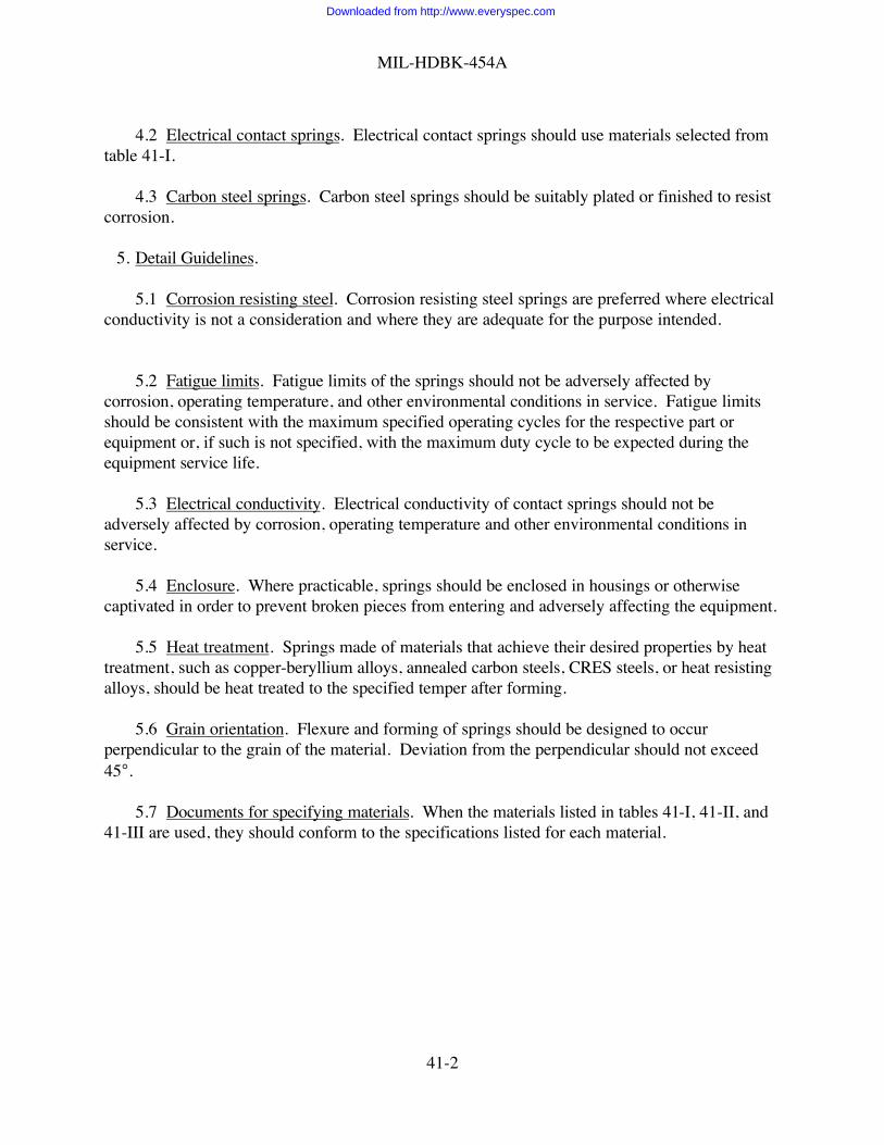
MIL-HDBK-454A
41-2
4.2 Electrical contact springs. Electrical contact springs should use materials selected fromtable 41-I.
4.3 Carbon steel springs. Carbon steel springs should be suitably plated or finished to resistcorrosion.
5. Detail Guidelines.
5.1 Corrosion resisting steel. Corrosion resisting steel springs are preferred where electricalconductivity is not a consideration and where they are adequate for the purpose intended.
5.2 Fatigue limits. Fatigue limits of the springs should not be adversely affected bycorrosion, operating temperature, and other environmental conditions in service. Fatigue limitsshould be consistent with the maximum specified operating cycles for the respective part orequipment or, if such is not specified, with the maximum duty cycle to be expected during theequipment service life.
5.3 Electrical conductivity. Electrical conductivity of contact springs should not beadversely affected by corrosion, operating temperature and other environmental conditions inservice.
5.4 Enclosure. Where practicable, springs should be enclosed in housings or otherwisecaptivated in order to prevent broken pieces from entering and adversely affecting the equipment.
5.5 Heat treatment. Springs made of materials that achieve their desired properties by heattreatment, such as copper-beryllium alloys, annealed carbon steels, CRES steels, or heat resistingalloys, should be heat treated to the specified temper after forming.
5.6 Grain orientation. Flexure and forming of springs should be designed to occurperpendicular to the grain of the material. Deviation from the perpendicular should not exceed45°.
5.7 Documents for specifying materials. When the materials listed in tables 41-I, 41-II, and41-III are used, they should conform to the specifications listed for each material.
Downloaded from http://www.everyspec.com
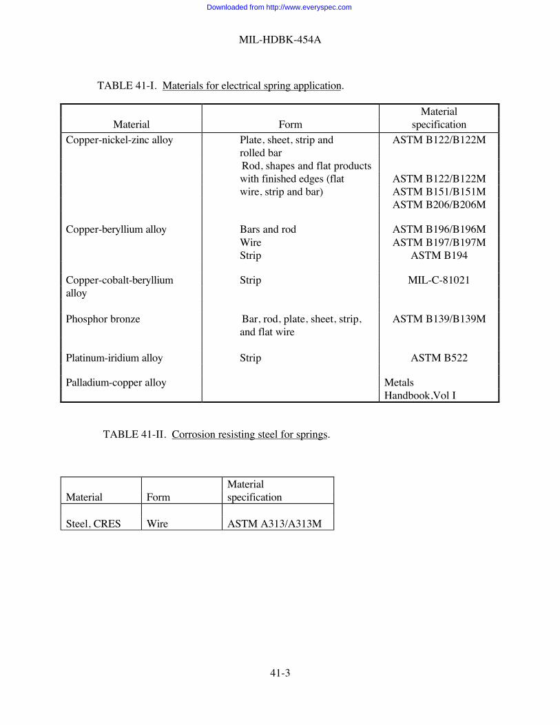
MIL-HDBK-454A
41-3
TABLE 41-I. Materials for electrical spring application.
MaterialMaterial Form specification
Copper-nickel-zinc alloy Plate, sheet, strip and ASTM B122/B122Mrolled barRod, shapes and flat productswith finished edges (flat ASTM B122/B122Mwire, strip and bar) ASTM B151/B151M
ASTM B206/B206M
Copper-beryllium alloy Bars and rod ASTM B196/B196MWire ASTM B197/B197MStrip ASTM B194
Copper-cobalt-beryllium Strip MIL-C-81021alloy
Phosphor bronze Bar, rod, plate, sheet, strip, ASTM B139/B139Mand flat wire
Platinum-iridium alloy Strip ASTM B522
Palladium-copper alloy MetalsHandbook,Vol I
TABLE 41-II. Corrosion resisting steel for springs.
MaterialMaterial Form specification
Steel, CRES Wire ASTM A313/A313M
Downloaded from http://www.everyspec.com
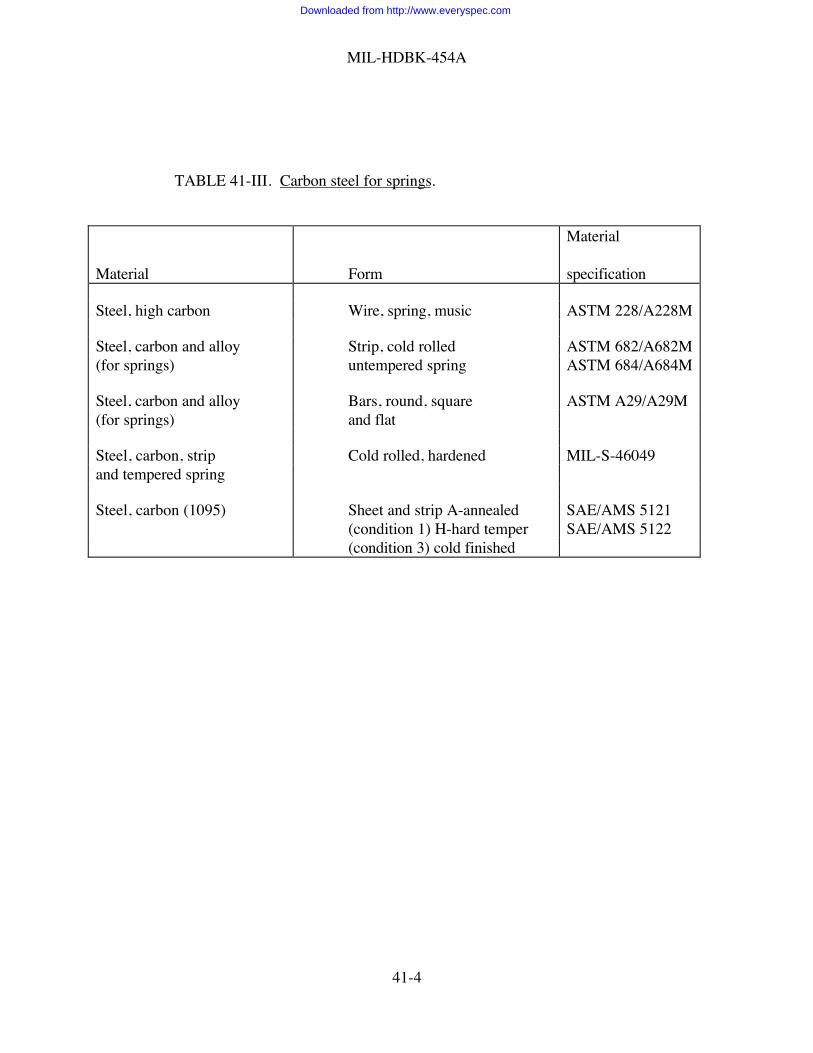
MIL-HDBK-454A
41-4
TABLE 41-III. Carbon steel for springs.
Material
Material Form specification
Steel, high carbon Wire, spring, music ASTM 228/A228M
Steel, carbon and alloy Strip, cold rolled ASTM 682/A682M(for springs) untempered spring ASTM 684/A684M
Steel, carbon and alloy Bars, round, square ASTM A29/A29M(for springs) and flat
Steel, carbon, strip Cold rolled, hardened MIL-S-46049and tempered spring
Steel, carbon (1095) Sheet and strip A-annealed SAE/AMS 5121(condition 1) H-hard temper SAE/AMS 5122(condition 3) cold finished
Downloaded from http://www.everyspec.com

MIL-HDBK-454A
42-1
GUIDELINE 42
TUNING DIAL MECHANISMS
1. Purpose. This guideline establishes criteria for the design of tuning dial mechanisms.
2. Applicable Documents. Not Applicable.
3. Definitions. Not applicable.
4. General Guidelines.
4.1 Dial. The division marking and lettering on tuning dials should be suitably etched. Dialmarkings should be legible at a distance of 0.6 meter from any point within a solid angle of 60°defined by a surface of revolution about a line through the center of the dial and perpendicular tothe panel. Minimum space between characters should be one stroke width. The width of thelubber line or pointer tip should not exceed the width of the graduation marks. Except for digitaltuning indicators, for which only one calibration number will be seen, dials should be marked sothat at least two calibration numbers on each band can be seen at any dial setting.
4.2 Balance and friction. Weighted tuning knobs should be counterbalanced. Friction in tuningdial mechanism should allow smooth and easy adjustment of the operating knob over the entireoperating range of the mechanism, but should have sufficient resistance or should incorporate apositive locking device to maintain the setting under all specified service conditions. Frictionshould be achieved through dry or elastic resistance rather than by fluid resistance.
4.3 Flexible control shafts. Flexible shaft assemblies should be used when a flexible mechanicalconnection is required between the tuning knob and the tuned device.
5. Detail Guidelines.
5.1 Tuning ratio. The tuning ratio used should be the optimum which will permit both rapidand precise setting.
Downloaded from http://www.everyspec.com

MIL-HDBK-454A
43-1
GUIDELINE 43
LUBRICANTS
1. Purposes. This guideline establishes criteria for the selection and application of lubricants.
2. Applicable Documents
VV-P-236 Petrolatum, TechnicalMIL-PRF-2105 Lubricating Oil, Gear, Multi-PurposeMIL-PRF-3150 Lubricating Oil, Preservative, MediumMIL-PRF-6085 Lubricating Oil, Instrument, Aircraft, Low VolatilityMIL-PRF-6086 Lubricating Oil, Gear, Petroleum BaseMIL-L-15719 Lubricating Grease (High-Temperature, Electric Motor, Ball and Roller
Bearings)MIL-L-17331 Lubricating Oil, Steam Turbine (Noncorrosive)MIL-PRF-17672 Hydraulic Fluid, Petroleum, InhibitedMIL-L-23398 Lubricant, Solid Film, Air Cured, Corrosion InhibitingMIL-PRF-23827 Grease, Aircraft and Instrument, Gear and Actuator ScrewMIL-G-24139 Grease, Multi-Purpose, Water ResistantDOD-G-24508 Grease, High Performance, Multi-Purpose (Metric)MIL-L-46010 Lubricant, Solid Film, Heat Cured, Corrosion InhibitingMIL-PRF-81322 Grease, Aircraft, General Purpose, Wide Temperature RangeMIL-PRF-81329 Lubricant, Solid Film, Extreme Environment29 CFR 1910 Code of Federal Regulations, Title 29, Chapter XVII, Part 1910
3. Definitions. Not applicable.
4. General Guidelines.
4.1 General. Lubricants should conform to one of the following:
VV-P-236 MIL-PRF-6086 MIL-G-24139MIL-PRF-2105 MIL-L-15719 DOD-G-24508MIL-PRF-3150 MIL-L-17331 MIL-L-46010MIL-L-3918 MIL-PRF-17672 MIL-PRF-81322MIL-PRF-6085 MIL-L-23398 MIL-PRF-81329
MIL-PRF-23827
4.2 Silicones. Silicone compounds should not be used as lubricants.
4.3 Graphite base lubricants. Graphite base lubricants should not be used.
5. Detail Guidelines
Downloaded from http://www.everyspec.com

MIL-HDBK-454A
43-2
5.1 Variety. The number of different lubricants should be held to a minimum.
5.2 Volatility. Low volatility lubricants should be used where practical.
5.3 Compatibility. The lubricant should be chemically inert with regard to the materials itcontacts.
5.4 Carcinogens. Certain chemicals have been identified in the occupational Safety andHealth Act (OSHA) as cancer-producing substances (carcinogens). Before using any materialswhich might contain these chemicals, they should be evaluated in accordance with 29 CFR 1910.Consideration of the toxicity of a substance should be given prior to material selection.
Downloaded from http://www.everyspec.com

MIL-HDBK-454A
44-1
GUIDELINE 44
FIBROUS MATERIALS, ORGANIC
1. Purpose. This guideline establishes criteria for the selection and application of organic fibrousmaterials.
2. Applicable Documents
V-T-285 Thread, PolyesterV-T-295 Thread, NylonMIL-W-530 Webbing, Textile, Cotton, General Purpose, Natural or in ColorsMIL-C-572 Cords, Yarns, and Monofilaments, Organic Synthetic FiberMIL-T-3530 Thread and Twine, Mildew Resistant or Water Repellent TreatedMIL-W-4088 Webbings, Textile, Woven NylonMIL-C-9074 Cloth, Laminated, Sateen, RubberizedMIL-W-27265 Webbing, Textile, Woven Nylon, ImpregnatedA-A-50197 Thread, LinenA-A-52094 Thread, Cotton29 CFR 1910 Code of Federal Regulations, Title 29, Chapter XVII, Part 1910
3. Definitions. Not applicable.
4. General Guidelines.
4.1 Webbing.
4.1.1 Cotton. Cotton webbing should conform to MIL-W-530, class 4 or 7. Class 7 shouldbe used when webbing will come in contact with natural or synthetic rubber or class 4 whenprolonged contact with the skin may occur.
4.1.2 Nylon. Nylon webbing should conform to MIL-W-4088 or class R of MIL-W-27265.
4.2 Cotton duck. Medium texture number 4 should be used for heavy-duty service and hardtexture number 12 should be used for services requiring light weight.
4.3 Thread. Thread should conform to A-A-52094, V-T-285, A-A-50197, or V-T-295.
4.3.1 Treatment. Cotton and linen thread should be treated in accordance withMIL-T-3530. Type I, class 2 mildew inhibiting agent should be used when thread will come incontact with natural or synthetic rubber or type I, class 1 when prolong contact with the skin mayoccur.
Downloaded from http://www.everyspec.com

MIL-HDBK-454A
44-2
4.4 Sateen. Laminated, two-ply rubberized cotton sateen should conform to MIL-C-9074.This sateen should not be used when prolonged contact with the skin may occur.
4.5 Cords, yarn, and monofilaments. Cords, yarns, and monofilaments should conform toMIL-C-572. Types PVCA, AR, VCR, and CTA should not be used where they may be exposedto fungus attack.
5. Detail Guidelines
5.1 Shrinkage. Fabric and thread should be preshrunk or allowance should be made forshrinkage in order to provide for satisfactory fit of finished items both before and after they areimmersed in water and then dried.
5.2 Carcinogens. Certain chemicals have been identified in the Occupational Safety andHealth Act (OSHA) as cancer producing substances (carcinogens). Before using any materialswhich might contain these chemicals, they should be evaluated in accordance with 29 CFR 1910.Consideration of the toxicity of a substance should be given prior to material selection.
Downloaded from http://www.everyspec.com
MIL-HDBK-454A
45-1
GUIDELINE 45
CORONA AND ELECTRICAL BREAKDOWN PREVENTION
1. Purpose. This guideline establishes criteria for the prevention of corona and electricalbreakdown.
2. Applicable Documents
ASTM D 149 Dielectric Breakdown Voltage and Dielectric Strength of SolidElectrical Insulating Materials at Commercial Power Frequencies
ASTM D 1868 Detection and Measurement of Partial Discharge (Corona) Pulses inEvaluation of Insulation Systems
3. Definitions.
3.1 Corona (air). A luminous discharge due to ionization of the air surrounding a conductorcaused by a voltage gradient exceeding a certain critical value, called the partial discharge(Corona) Inception Voltage (CIV).
3.2 Partial discharge (corona) inception voltage (CIV). The lowest rms voltage at whichcontinuous partial discharges above some stated magnitude (which may define the limit ofpermissible background noise) occur as the applied voltage is gradually increased.
3.3 Partial discharge (corona) extinction voltage (CEV). The highest rms voltage at whichpartial discharges above some stated magnitude no longer occur as the applied voltage isgradually decreased from above the inception voltage.
3.4 Breakdown. A disruptive discharge through insulation, involving a sudden and largeincrease in current through the insulation because of complete failure under electrostatic stress,also called puncture.
4. General Guidelines.
4.1 Corona prevention. The CEV should be at least 150 percent of the peak circuit voltage,corresponding to the maximum specified steady-state rms supply voltage. This guideline applies:
a. When the equipment is terminated with the cabling or other accessory equipment withwhich it is intended to be used and;
b. When the equipment is operated under the specified environmental service conditions and;
c. When the equipment is supplied with the specified power source frequencies and voltagesincluding commonly recurring transients.
Downloaded from http://www.everyspec.com

MIL-HDBK-454A
45-2
4.2 Electrical breakdown prevention. The equipment should be designed and manufacturedwith electrical clearance spacing, leakage (creepage) distances, and insulation characteristicsadequate to prevent electrical breakdown. This guideline applies under all specifiedenvironmental service conditions including service life and using the specified operating voltages(including transients). Liquid dielectrics, gases other than air, or pressurization to preventelectrical breakdown should not be used unless approved by the procuring activity.
5. Detail Guidelines.
5.1 Effects of corona. Corona occurring at the interface of an insulator and a metal candamage or reduce the life of an insulating system. In general, inorganic insulating materials aremore resistant to the damaging effects of corona than organic insulating materials. Corona alsogenerates electromagnetic interference and liberates ozone, a toxic, oxidant gas.
5.2 Insulation systems. Corona can occur within cavities between an insulating material anda metal surface which are in contact. Therefore, care should be exercised to avoid cavities at suchinterfaces where high voltages are encountered.
5.3 Metal parts. Sharp edges and points should be avoided on metal parts which areincluded in high intensity electric fields.
5.4 Corona testing. There are many factors which determine whether or not corona willoccur, including temperature, humidity, ambient pressure, test specimen shape, rate of voltagechange and the previous history of the applied voltage. Test methods such as ASTM D 1868 maybe used but the test results lack accuracy and repeatability and require great care due to thepersonnel hazards involved.
5.5 Electrical breakdown testing. The breakdown voltage of a given insulating material isdependent upon electrode size and shape, insulator thickness, temperature, humidity, rate ofvoltage application, voltage waveform and voltage frequency. When testing, care must beexercised to assure that the insulating material is evaluated under the actual environmentalconditions which apply to the equipment and that the occurrence of corona or localized heatingdoes not mask the true breakdown voltage. Provides a test usable at power frequencies, 25 to800 Hz ASTM D 149.
Downloaded from http://www.everyspec.com

MIL-HDBK-454A
46-1
GUIDELINE 46
MOTORS AND ROTARY POWER CONVERTERS
1. Purpose. This guideline establishes criteria for the selection and application of motors androtary power converters.
2. Applicable Documents.
MIL-M-17059 Motor, 60 Cycle, Alternating Current, Fractional Horsepower(Shipboard Use)
MIL-M-17060 Motors, 60 Hertz, Alternating Current, Integral Horsepower(Shipboard Use)
MIL-B-23071 Blowers, Miniature, for Cooling Electronic Equipment, GeneralSpecification for
3. Definitions. Not applicable.
4. General Guidelines.
4.1 Motors - alternating current. Alternating current motors should conform to MIL-M-17059or MIL-M-17060, except that any motor used with a miniature blower for cooling electronicequipment should be in accordance with MIL-B-23071.
5. Detail Guidelines. Not applicable.
Downloaded from http://www.everyspec.com

MIL-HDBK-454A
47-1
GUIDELINE 47
ENCAPSULATION AND EMBEDMENT (POTTING)
1. Purpose. This guideline establishes criteria for encapsulating and embedding (potting) a part oran assembly of discrete parts. Conformal coating of printed circuit assemblies is excluded fromthis guideline.
2. Applicable Documents.
MIL-PRF-8516 Sealing Compound, Synthetic Rubber, Electric Connectors and ElectricSystems, Chemically Cured
MIL-I-16923 Insulating Compound, Electrical, EmbeddingMIL-PRF-23586 Sealing Compound, (with Accelerator), Silicone Rubber, ElectricalMIL-M-24041 Molding and Potting Compound, Chemically Cured, Polyurethane (Polyether
Based)MIL-I-81550 Insulating Compound, Electrical, Embedding, Reversion Resistant Silicone29 CFR 1910 Code of Federal Regulations, Title 29, Chapter XVII, Part 1910
3. Definitions.
3.1 Encapsulation. A process for encasing a part or an assembly of discrete parts within aprotective material which is generally not over 2.5 mm thick and does not require a mold orcontainer.
3.2 Embedment (potting). A process for encasing a part or an assembly of discrete partswithin a protective material which is generally over 2.5 mm thick, varies in thickness, fills theconnecting areas within an assembly, and requires a mold or container to confine the materialwhile it is hardening. Potting is an embedding process where the protective material bonds to themold or container so that it becomes integral with the item.
4. General Guidelines.
4.1 Encapsulation and Embedment Materials. Encapsulation and embedment materialsshould be of a nonreversion type and should be selected from the following specifications:MIL-S-8516, MIL-I-16923, MIL-S-23586, MIL-M-24041, and MIL-I-81550. The materialsselected should be capable of filling all voids and air spaces in and around the items being encased.For Air Force applications, approval for use of any material other than transparent silicone inaccordance with MIL-I-81550 should be requested through the procuring activity.
5. Detail Guidelines.
5.1 Selection. The following points should be considered when selecting an encapsulation orembedment material:
Downloaded from http://www.everyspec.com

MIL-HDBK-454A
47-2
a. Need for precautions due to hazardous characteristics of the material.
b. Electrical, mechanical and thermal properties, including tear resistance, resistance to flame,chemicals, moisture, water, humidity, fungus, and temperature extremes.
c. Color or transparency.
d. Dissipation factor.
e. Specific gravity.
f. Shrinkage.
g. Heat distortion parameters.
h. Stresses on parts.
i. Durometer hardness.
j. Adhesion to substrates (and priming).
k. Temperatures of application and curing.
l. Repairability.
m. Dielectric constant.
n. Volume resistivity.
o. Reversion resistance, including hydrolytic stability.
p. Viscosity.
q. Solvent affects.
r. Compatibility with parts or assemblies to which applied.
5.2 Application. The encapsulation or embedment of microelectronic modules and equipmentmodules should be avoided, except where specifically indicated by the requirements of a particularapplication. In such instances, the module design should be completely verified for the particularencapsulation or embedment materials and processes to be employed. Any changes in moduledesign, materials, and processes may require re-evaluation of the modules. In particular, extremetemperature aging and temperature cycling tests combined with random vibration screeningshould be performed to verify adequacy of the design. Design considerations should addressthermal coefficent of expansion mismatches between potting material and components and stress
Downloaded from http://www.everyspec.com

MIL-HDBK-454A
47-3
relief techniques. Wherever economically feasible, the module to be encapsulated or embeddedshould be designed as a throw-away unit.
5.3 Carcinogens. Certain chemicals have been identified in the Occupational Safety andHealth Act (OSHA) as cancer-producing substances (carcinogens). Before using any materialswhich might contain these chemicals, they should be evaluated in accordance with 29 CFR 1910.Consideration of the toxicity of a substance should be given prior to material selection.Consideration of hazards should address all stages of the equipment lifecycle from fabrication toassembly, to installation, use maintenance and decomposition during failure analysis andtroubleshooting.
Downloaded from http://www.everyspec.com

MIL-HDBK-454A
48-1
GUIDELINE 48
GEARS
1. Purpose. This guideline establishes criteria for the selection and application of gears.
2. Applicable Documents.
Index American Gear Manufacturers Association (AGMA)
3. Definitions. Not applicable.
4. General Guidelines.
4.1 Gears. Gears not operating in a lubricant bath should be made of corrosion resistant materials. Gearsoperating in a lubricant bath containing a corrosion inhibiting additive may be made of noncorrosion resistantmaterials.
5. Detail Guidelines.
5.1 Designation. Gears should be designated, dimensioned, toleranced and inspected in accordance with theapplicable AGMA specifications.
5.2 Planetary or epicyclic gearing. Planetary or epicyclic gearing is preferred to worm gearing.
5.3 Nonmetallic gears. Nonmetallic gears may be used when they meet load, life, and environmentalrequirements of the applicable specification.
Downloaded from http://www.everyspec.com

MIL-HDBK-454A
49-1
GUIDELINE 49
HYDRAULICS
1. Purpose. This guideline establishes criteria for the design and installation of a hydraulic systemwhen it functions as an integral part of an electronic system.
2. Applicable Documents.
ANSI B93.1 Fluid Power Cylinders, Dimension Identification Code forANSI B93.2 Fluid Power, Glossary of Terms forANSI B93.3 Cylinder Bore and Piston Rod Sizes for Fluid Power CylindersANSI B93.4 Electric Resistance Welded Mandrel Drawn Hydraulic Line TubingANSI B93.5 Use of Fire-Resistant Fluids for Fluid Power Systems, Practices for theANSI B93.6 Mounting Flanges and Shafts for Positive Displacement Fluid Power
Pumps and Motors, Dimensions andIdentification Code for
ANSI B93.7 Mounting Surfaces of Sub-Plate Type Hydraulic Fluid Power Valves,Dimensions for
ANSI B93.8 Bore and Rod Size Combinations and Rod End Configurations forCataloged Square Head Industrial Fluid Power Cylinders
ANSI B93.9 Symbols for Marking Electrical Leads and Ports on Fluid Power ValvesANSI B93.10 Static Pressure Rating Methods of Square Head Fluid Power CylindersANSI B93.11 Seamless Low Carbon Steel Hydraulic Line TubingANSI SAE J514 Hydraulic Tube FittingsANSI SAE J518 Hydraulic Flanged Tube and Hose Connections, 4 Bolt, Split Flanged TypeSAE AS5440 Hydraulic Systems, Aircraft, Design and Installation, Requirements for
3. Definitions. Not applicable.
4. General Guidelines.
4.1 Aircraft or manned flight vehicles. The design and installation of hydraulic systems foraircraft or manned flight vehicles should conform to the applicable type and class or systemdescribed in MIL-H-5440.
5. Detail Guidelines. The following documents contain additional information on hydraulicdesign:
ANSI B93.1 ANSI B93.8 ANSI B93.2 ANSI B93.9 ANSI B93.3 ANSI B93.10 ANSI B93.4 ANSI B93.11 ANSI B93.5 ANSI SAE J514 ANSI B93.6 ANSI SAE J518 ANSI B93.7
Downloaded from http://www.everyspec.com

MIL-HDBK-454A
50-1
GUIDELINE 50
INDICATOR LIGHTS
1. Purpose. This guideline establishes criteria for selection and application of indicator lights andassociated items.
2. Applicable Documents.
MIL-L-3661 Lampholders, Indicator Lights, Indicator-Light Housings, andIndicator-Light Lenses, General Specification for
MIL-DTL-6363 Lamps, Incandescent, Aircraft Service, General Requirements forMIL-L-7961 Lights, Indicators, Press to TestMIL-L-15098 Lamp, Glow, General Specification forMIL-PRF-19500 Semiconductor Devices, General Specification forMIL-STD-1472 Human Engineering
3. Definitions. Not applicable.
4. General Guidelines.
4.1 Lights and accessories. Indicator lights, indicator light housings, lampholders, lenses,and lamps should be selected in accordance with table 50-I.
4.2 Visual display and legend lights. Visual display and legend lights should comply withthe requirements in MIL-STD-1472.
4.3 Light emitting diodes (LED's). LED's when used as indicator lights should conform tothe applicable specification sheets of MIL-PRF-19500.
4.4 Night Vision Goggles. Night Vision Goggle compatibility considerations for cockpitindicator lights should be considered where use of night vision goggles by cockpit crews ispossible.
5. Detail Guidelines. Not applicable.
Downloaded from http://www.everyspec.com

MIL-HDBK-454A
50-2
TABLE 50-I. Indicator lights and associated items.
MIL-L- MIL-L- MIL-L- MIL-L- MIL-PRF-3661 6363 7961 15098 19500
Indicator lights X X X
Indicatorlight housings XLamp holders X
Lenses XIncandescent Xlamps, generalpurposeIncandescent Xlamps, severeenvironmentNeon lamps X
Downloaded from http://www.everyspec.com

MIL-HDBK-454A
51-1
GUIDELINE 51
METERS, ELECTRICAL INDICATING
1. Purpose. This guideline establishes criteria for the selection and application of electricalmeters.
2. Applicable Documents.
MIL-M-7793 Meter, Time TotalizingMIL-M-16034 Meter, Electrical Indication (Switchboard and Portable Types)MIL-M-16125 Meters, Electrical, Frequency
3. Definitions. Not applicable.
4. General Guidelines.
4.1 Meters . Meters should conform to one of the following specifications: MIL-M-7793,MIL-M-16034, or MIL-M-16125.
5. Detail Guidelines.
5.1 Analog Meters. For analog meters, the normal operating value of the quantity to beindicated should be between 0.3 and 0.8 of full-scale deflection, wherever practicable.
Downloaded from http://www.everyspec.com

MIL-HDBK-454A
52-1
GUIDELINE 52
THERMAL DESIGN
1. Purpose. This guideline establishes criteria for thermal design.
2. Applicable Documents.
MIL-F-16552 Filter, Air Environmental Control System, Cleanable, Impingement(High Velocity Type)
MIL-B-23071 Blowers, Miniature, for Cooling Electronic Equipment, GeneralSpecification for
MIL-HDBK-251 Reliability/Design, Thermal ApplicationsASTM F 872 Filter Units, Air Conditioning: Viscous-Impingement Types, Cleanable
3. Definitions.
3.1 Auxiliary heating or cooling. External heating or cooling devices not normally part of theequipment configuration.
3.2 Cold plate. A heat transfer surface cooled by forced air or other heat transfer fluid towhich heat dissipating parts are mounted.
3.3 Contaminant. Any foreign substance contained in air or other heat transfer fluid whichadversely affects cooling performance, such as dust particles, lint, oil, sludge, etc.
3.4 Direct impingement. Passing cooling air over parts without the use of cold plates or heatexchangers.
3.5 Entrained water. Water condensed from the cooling air and carried along with the coolingair.
3.6 External source supplied cooling air. Forced air supplied from a conditioning source suchas an air conditioner or aircraft environmental control system which is not normally a part of theelectronic equipment.
3.7 Forced air cooling. The dissipation of heat to cooling air, including ram air, supplied by asource with sufficient pressure to flow through the unit.
3.8 Heat exchanger. An air-to-air or liquid-to-air finned duct arrangement which is used totransfer dissipated heat from a hot recirculating fluid to the cooling fluid by conduction throughthe finned surfaces.
3.9 Natural cooling. The dissipation of heat to surroundings by conduction, convection,radiation, or any combination thereof without the benefit of external cooling devices.
Downloaded from http://www.everyspec.com
MIL-HDBK-454A
52-2
3.10 Part. An element or component used in the production of an electronic equipment orsubsystem, such as a microcircuit, diode, transistor, capacitor, resistor, relay switch, ortransformer.
3.11 Pressure drop (differential pressure). Resistance to flow usually measured as the staticpressure difference across the electronic equipment from inlet to coolant outlet.
4. General Guidelines.
4.1 Forced air cooling. Forced air cooling should be used only when natural cooling is notadequate. Exhaust and recirculating fans and blowers should be driven by ac brushless motors orby properly shielded dc motors. Miniature blowers should conform to MIL-B-23071. Air filtersshould be provided for air intakes for fan and blower cooled units when required to protectinternal parts. Filters, when used, should conform to ASTM F 872 or MIL-F-16552, and shouldbe removable for cleaning without disassembly of the equipment. All ventilation openings shouldbe designed and located to comply with electromagnetic interference, undesired radiation andenclosure guidelines. Air exhaust should be directed away from operating personnel.
4.1.1External source. For equipment designed for use with external source supplied coolingair, which may contain entrained water or other contaminants detrimental to the equipment,precautionary measures should be taken to avoid direct impingement on internal parts andcircuitry by channeling or use of heat exchangers.
4.1.2Aircraft application. Equipment that is intended for use in aircraft and requires forced aircooling should be designed using cold plates or heat exchangers so that none of the cooling airwill come into contact with internal parts, circuitry, or connectors.
4.2 Other cooling methods. Prior approval of the procuring activity should be obtained whenheat densities or other design requirements make the use of air for cooling impractical andalternate methods, such as liquid, evaporative, change of phase material, or heat pipes, arerequired.
5. Detail Guidelines.
5.1 Fan and Blower Characteristics. The design factors which should be considered indetermining the required fan or blower characteristics include such factors as amount of heat to bedissipated, the quantity of air to be delivered at the pressure drop of the enclosed equipment, theallowable noise level, the permissible level of heat that may be exhausted into the surroundingenvironment, and other pertinent factors affecting the cooling requirements of the equipment.Induced drafts and ventilation by means of baffles and internal vents should be used to thegreatest practicable extent. When practicable, ventilation and air exhaust openings should not belocated in the top of enclosures or in front panels. When it is impractical to avoid directimpingement on internal parts and circuitry by channeling or use of heat exchangers, the water
Downloaded from http://www.everyspec.com

MIL-HDBK-454A
52-3
and contaminants should be removed from the cooling air by suitable water and contaminantremoval devices.
5.2 External source. For equipment designed for use with external source supplied cooling air,minimum differential pressure (pressure drop) of the cooling air through the equipment heatexchanger or cold plate should be maintained, consistent with adequate cooling.
5.3 Design guidance. MIL-HDBK-251 may be used as a guide for detail information onthermal design of electronic equipment.
Downloaded from http://www.everyspec.com

MIL-HDBK-454A
53-1
GUIDELINE 53
WAVEGUIDES AND RELATED DEVICES
1. Purpose. This guideline establishes criteria for the selection and application of waveguidesand related devices.
2. Applicable Documents.
MIL-DTL-85 Waveguides, Rigid, Rectangular, General Specification forMIL-DTL-287 Waveguides, Assembly, Twisted, and Non-Twisted, General
Specification forMIL-F-3922 Flange Waveguides, General Purpose, General Specification forMIL-S-3928 Switches, Radio Frequency Transmission Line (Coaxial), General
Specification forMIL-A-3933 Attenuators, Fixed, General Specification forMIL-D-3954 Dummy Loads, Electrical, Waveguide, General Specification forMIL-DTL-3970 Waveguides, Assembly, Rigid, General Specification forMIL-C-15370 Couplers, Directional, General Specification forMIL-C-18277 Coupler, Antenna, CU-351/AR and Coupler Antenna CU-509/ARMIL-D-18576 Dummy Load, Electrical, Navy Type 14ACNMIL-DTL-22641 Adapter, Coaxial to Waveguide, General Specification forMIL-P-23971 Power Dividers, Power Combiners, and Power Dividers/Combiners,
General Specification forMIL-DTL-24044 Flange, Coaxial Line, Rigid Air Dielectric, General Specification forMIL-S-24067 Switch, Coaxial, Radio Frequency Transmission Line (for use with
Electronic Countermeasures Equipment), General Specification forMIL-DTL-24211 Gaskets, Waveguide Flange, General Specification forMIL-PRF-25879 Switch, Radio Frequency Transmission Line, Coaxial Type SA-521
A/A and Mounting MT-1995/AMIL-C-28790 Circulator, Radio Frequency, General Specification forMIL-I-28791 Isolator, Radio Frequency, General Specification forMIL-C-28806 Coupler Group, Antenna, AN/URA-38 ( )MIL-M-28837 Mixer Stages, Radio Frequency, General Specification forMIL-A-28875 Amplifier, Radio Frequency and Microwave, Solid State, General
Specification forMIL-DTL-39030 Dummy Loads, Electrical, Coaxial and Stripline, General Specification
forMIL-S-55041 Switches, Waveguide, General Specification forMIL-HDBK-216 RF Transmission Lines and FittingsMIL-HDBK-660 Fabrication of Rigid Waveguide Assemblies (Sweep Bends and Twists)
3. Definitions. Not applicable.
4. General Guidelines.
Downloaded from http://www.everyspec.com

MIL-HDBK-454A
53-2
4.1 Waveguides and related devices. Waveguides and related devices should be selected inaccordance with the standards appearing in table 53-I and should conform to a specification listedin the table or to a specification imposed by the listed standard.
5. Detail Guidelines.
5.1 RF transmission lines and fittings. MIL-HDBK-216 should be used as a technicalinformation guide for RF transmission lines and fittings.
5.2 Rigid waveguide assemblies. MIL-HDBK-660 should be used as a guide to thefabrication of rigid waveguide assemblies where bends and twists are required to satisfy aparticular application.
Downloaded from http://www.everyspec.com

MIL-HDBK-454A
53-3
TABLE 53-I. Waveguides and related devices.
Applicable
Item description Document
Amplifier, RF and microwave DIP, coaxial, TO, andflatpack MIL-A-28875
Attenuators Fixed and variablecoaxial and waveguide MIL-A-3933
Circulators RF-SMA and waveguide MIL-C-28790
Couplers Directional coaxialwaveguide and prtd ckt MIL-C-15370
MIL-C-18277MIL-C-28806
Coupling assemblies Quick-disconnect for MIL-STD-1327subminiature waveguide MIL-D-3954flanges
Dummy loads Waveguide, coaxialand stripline MIL-D-18576
MIL-PRF-39030Flanges Waveguide and coaxial MIL-STD-1327
MIL-F-3922MIL-F-24044
Gaskets Pressure sealing for MIL-DTL-24211use with cover flangesand flat face
Isolators RF-SMA and stripline MIL-I-28791
Mixer stages RF-DIP, flatpack,TO and connector MIL-M-28837
Power dividers, combiners Solder terminals,and divider/combiners plug-in, flatpack, MIL-P-23971
TO and connector
Switches Waveguide to waveguide MIL-S-55041manual and electro MIL-S-3928mechanically operated MIL-S-24067
MIL-PRF-25879RF coaxial
Waveguide assemblies Flexible and rigidMIL-DTL-287MIL-DTL-3970MIL-HDBK-660
Waveguides Rigid rectangularrigid circular, single MIL-DTL-85and double ridge
MIL-A-22641
Downloaded from http://www.everyspec.com

MIL-HDBK-454A
54-1
GUIDELINE 54
MAINTAINABILITY
1. Purpose. This guideline offers guidance as to maintainability which may be considered whenpreparing contractual documents. Maintainability program tasks, quantitative requirements, andverification or demonstration requirements may be directly specified in the contract or thesystem/equipment specification, as appropriate.
2. Applicable Documents.
MIL-HDBK -470 Maintainable Programs for System and EquipmentMIL-HDBK-472 Maintainability Prediction
3. Definitions. Not applicable.
4. General Guidelines. Not applicable.
5. Detail Guidelines.
5.1 Maintainability program. Maintainability engineering and accounting tasks aimed atpreventing, detecting, and correcting maintainability design deficiencies and providingmaintainability related information essential to acquisition, operation, and support managementshould be included in contract requirements with the objective of establishing and maintaining anefficient maintainability program according to life cycle phase. MIL-HDBK-470 is the overallprogram document for the area. MIL-HDBK-472 provides additional guidance.
5.2 Quantitative requirements. Quantitative maintainability requirements and verification ordemonstration requirements should be established as appropriate to program phase.
Downloaded from http://www.everyspec.com

MIL-HDBK-454A
55-1
GUIDELINE 55
ENCLOSURES
1. Purpose. This guideline establishes criteria for the design and construction of enclosures.
2. Applicable Documents.
MIL-F-85731 Fastener, Positive Locking, Electronic Equipment, GeneralSpecification for
MIL-STD-108 Definitions of and Basic Requirements for Enclosures for Electric andElectronic Equipment
EIA-310 Cabinets, Racks, Panels, and Associated Equipment
3. Definitions.
3.1 Enclosures. Enclosures are housings such as consoles, cabinets, and cases, which aredesigned to provide protection and support to mechanisms, parts, and assemblies.
4. General Guidelines.
4.1 Cases and mounting bases for airborne equipment. Materials, bonding, shielding andperformance requirements of MIL-F-85731 should apply to all cases. Mounting bases shouldconform to MIL-F-85731, as applicable.
4.2 Degree of enclosure. Enclosures should be designed in accordance with MIL-STD-108,table I for the degree of enclosure best suited to the application. Moisture absorbent materialssuch as open-celled foam should not be used to fill moisture pockets.
4.3 Materials. Materials used should be corrosion and deterioration resistant or coated toresist corrosion and deterioration.
4.4 Racks and panels. The internal clearance and the equipment mounting holes of racks andpanels should be in accordance with EIA -310.
4.5 Test guidelines. Enclosures should be tested as specified in MIL-STD-108.
5. Detail Guidelines.
5.1 Cases for aerospace ground support equipment. The equipment specification or contractfor the particular equipment will specify the type of case to be supplied by the contractor. Transitcases and combination type cases may not be required for ship, depot, or field shops wherever thearea of use is protected or controlled for human occupancy.
Downloaded from http://www.everyspec.com

MIL-HDBK-454A
55-2
5.2 Desiccants. Where moisture build up in sealed equipment cannot be tolerated, the use ofdesiccants or dehydrating agents should be considered.
5.3 Materials. Materials for the enclosure should be the lightest practical consistent with thestrength required for sturdiness, serviceability and safety.
Downloaded from http://www.everyspec.com

MIL-HDBK-454A
56-1
GUIDELINE 56
ROTARY SERVO DEVICES
1. Purpose. This guideline establishes criteria for the selection and application of rotary servodevices such as servomotors, synchros, electrical resolvers, tachometer generators, encoders, andtransolvers.
2. Applicable Documents.
MIL-S-22432 Servomotors, General Specification MIL-S-22820 Servomotor-Tachometer Generator AC, General Specification for MIL-T-22821 Tachometer Generator AC, General Specification for
MIL-S-81746 Servtorqs, General Specification for MIL-S-81963 Servo Components, Precision Instrument, Rotating, Common
Requirements and Tests, General Specification forMIL-E-85082 Encoders, Shaft Angle to Digital, General Specification for
MIL-STD-710 Synchros, 60 and 400 Hz, Selection and Application of,MIL-HDBK-225 Synchros, Description and Operation
MIL-HDBK-231 Encoder, Shaft Angle to Digital
3. Definitions. Not applicable.
4. General Guidelines.
4.1 Rotary servo devices. Rotary servo devices should conform to MIL-S-81963 as applicable.
4.2 Servomotors. Servomotors should conform to MIL-S-22432.
4.3 Synchros. Synchros should be selected and applied in accordance with MIL-STD-710.
4.4 Tachometer generators. Tachometer generators should conform to MIL-T-22821.
4.5 Encoders. Encoders should conform to MIL-E-85082 for general application.
4.6 Servomotor-tachometer generators. Servomotor-tachometer generators should conform toMIL-S-22820.
4.7 Servtorqs. Servtorqs should conform to MIL-S-81746.
4.8 Application Information. The following documents contain additional information forapplication:
MIL-HDBK-225 MIL-HDBK-231
5. Detail Guidelines. Not applicable.
Downloaded from http://www.everyspec.com

MIL-HDBK-454A
57-1
GUIDELINE 57
RELAYS
1. Purpose. This document is intended to be a general guide to aid the designer in the appropriateselection of a relay for his intended application.
2. Applicable Documents.
MIL-R-5757 Relays, Electromagnetic, General Specification ForMIL-PRF-6106 Relays, Electromagnetic, General Specification For.MIL-PRF-28750 Relays, Solid-State, Sealed, General Specification For.MIL-PRF-28776 Relays, Hybrid, Established Reliability, General Specification For.MIL-PRF-39016 Relays, Electromagnetic, Established Reliability, General
Specification For.MIL-PRF-83536 Relays, Electromagnetic, Established Reliability, General
Specification For.MIL-PRF-83726 Relays, Hybrid and Solid State, Time Delay, General Specification
For.
3. Definitions.
3.1 Relay. A relay is defined as an electrically controlled device that opens and closeselectrical contacts or activates and deactivates operation of other devices in the same or anotherelectrical circuit. Two types of relay technology are available, mechanical and solid state. Amechanical relay is essentially a combination of an inductor and a switch, where theelectromagnetic force of the inductor causes a switch to change position. A solid state relayaccomplishes the same function with semiconductor devices changing impedance to effectivelyactivate or deactivate a circuit open or closure
3.2 Type. Relays are classified into four general application categories, dependent on theload levels they are designed to switch. A definition of each follows:
3.2.1Low Level: Relays intended for switching low currents, typically in the milliampere range.In these circuits, only the mechanical force between the contacts affects the physical condition ofthe contact interface. There are no thermal or electrical affects, such as arcing.
3.2.2 Intermediate Level: Relays used in load applications where there is insufficient contactarcing to effectively remove surface residue from the organic vapor deposits on the contactsurface. However, there may be sufficient energy to cause melting of the contact material.
3.2.3Power: Relays intended for switching high current loads, typically in excess of 25 A.Significant arcing occurs and the relay is designed with sufficient design margin to withstand thecontinuous arcing for a given number of cycles.
Downloaded from http://www.everyspec.com

MIL-HDBK-454A
57-2
3.2.4Special Purpose: Sensor, hybrid, and time delay relays are classified as special purposerelays intended for specific applications. A sensor relay is designed to detect specific functions,such as frequency drift, out of phase conditions, voltage level, etc., and produce the appropriateswitching response. A hybrid relay has an isolated input and output. This is accomplishedthrough a solid state device, which controls the electromagnetic output. A mechanical time delayrelay incorporates a conductive slug or sleeve on the core, which produces a counter-magnetomotive force and results in a switching delay. For solid state time delay relays, a separatecircuit is incorporated within the device to produce the time delay.
4. General Guidelines. Standardized military relays are segregated by the specifications listed inTable 57-1. Relays can further be segregated by sensitivity, or how much current is necessary toswitch the relay. Increased sensitivity in non-solid state relays is accomplished by increasing thenumber of inductive windings inside the relay, which increases resistance.
Table 57-1: Military Relay SpecificationsMilitarySpecification
Description
MIL-R-5757 Relays, Electromagnetic, GeneralSpecification For
MIL-PRF-6106 Relays, Electromagnetic, GeneralSpecification For
MIL-PRF-28776
Relays, Hybrid, EstablishedReliability, General SpecificationFor
MIL-PRF-39016
Relays, Electromagnetic,Established Reliability, GeneralSpecification For
MIL-PRF-28750
Relays, Solid-State, GeneralSpecification For
MIL-PRF-83726
Relays, Hybrid and Solid State,Time Delay, General SpecificationFor
MIL-PRF-83536
Relays, Electromagnetic,Established Reliability
4.1 Selection.Quality and reliability levels of relays may be expressed as the number of switchcycles before wear-out rather than the more traditional failure rate. Vendors consider ratednumber of switch cycles to be the guaranteed minimum number of cycles the relay can withstandunder normal operating conditions before failure (intermittent or constant). Quality is furtherdependent on the ruggedness of the package and how well the internal switching elements aresealed against influences of the outside environment. Commercial grade relays and relays found inCOTS equipment are not routinely acceptable for use in Military environments. Some relayvendors will advertise ISO 9000 quality systems or state they are ISO 9000 certified. Manymanufacturers will then give a higher vendor rating (or increased preference) to the ISO 9000
Downloaded from http://www.everyspec.com
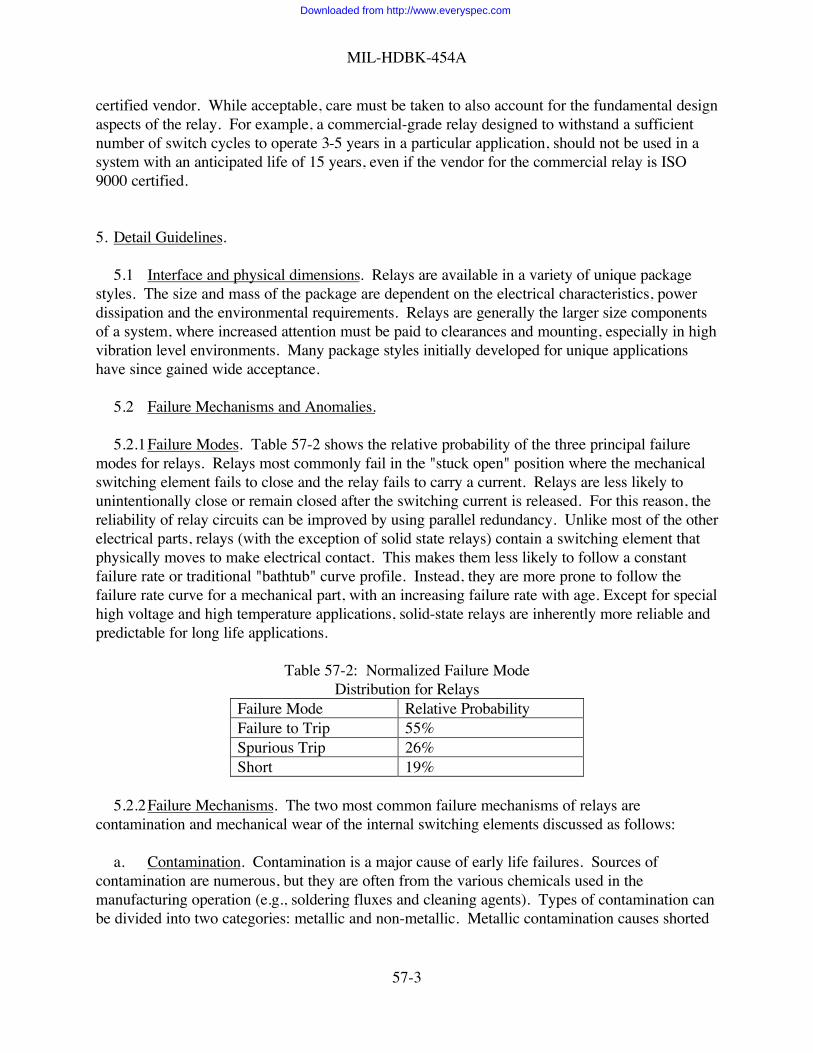
MIL-HDBK-454A
57-3
certified vendor. While acceptable, care must be taken to also account for the fundamental designaspects of the relay. For example, a commercial-grade relay designed to withstand a sufficientnumber of switch cycles to operate 3-5 years in a particular application, should not be used in asystem with an anticipated life of 15 years, even if the vendor for the commercial relay is ISO9000 certified.
5. Detail Guidelines.
5.1 Interface and physical dimensions. Relays are available in a variety of unique packagestyles. The size and mass of the package are dependent on the electrical characteristics, powerdissipation and the environmental requirements. Relays are generally the larger size componentsof a system, where increased attention must be paid to clearances and mounting, especially in highvibration level environments. Many package styles initially developed for unique applicationshave since gained wide acceptance.
5.2 Failure Mechanisms and Anomalies.
5.2.1Failure Modes. Table 57-2 shows the relative probability of the three principal failuremodes for relays. Relays most commonly fail in the "stuck open" position where the mechanicalswitching element fails to close and the relay fails to carry a current. Relays are less likely tounintentionally close or remain closed after the switching current is released. For this reason, thereliability of relay circuits can be improved by using parallel redundancy. Unlike most of the otherelectrical parts, relays (with the exception of solid state relays) contain a switching element thatphysically moves to make electrical contact. This makes them less likely to follow a constantfailure rate or traditional "bathtub" curve profile. Instead, they are more prone to follow thefailure rate curve for a mechanical part, with an increasing failure rate with age. Except for specialhigh voltage and high temperature applications, solid-state relays are inherently more reliable andpredictable for long life applications.
Table 57-2: Normalized Failure ModeDistribution for Relays
Failure Mode Relative ProbabilityFailure to Trip 55%Spurious Trip 26%Short 19%
5.2.2Failure Mechanisms. The two most common failure mechanisms of relays arecontamination and mechanical wear of the internal switching elements discussed as follows:
a. Contamination. Contamination is a major cause of early life failures. Sources ofcontamination are numerous, but they are often from the various chemicals used in themanufacturing operation (e.g., soldering fluxes and cleaning agents). Types of contamination canbe divided into two categories: metallic and non-metallic. Metallic contamination causes shorted
Downloaded from http://www.everyspec.com

MIL-HDBK-454A
57-4
conditions or blocks the physical movement of mechanical elements. Non-metallic or gaseouscontamination creates open circuits when it periodically deposits itself on contacts.
b. Mechanical Wear. A second major cause of early life failures in relays is mechanical wearof internal switching elements. In fact, the life of a relay is essentially determined by the life of itscontacts. Degradation of contacts is caused from high inrush currents, high-sustained currents,and from high voltage spikes. The source of high currents and voltages, in turn, are determinedby the type of load. Inductive loads create the highest voltage and current spikes because theyhave lowest starting resistance compared to operating resistance. This is especially true for lampfilaments and motors, which is why derating is more severe for these types of loads. The life of acontact can be further degraded if contamination or pitting is present on the contact. Physicalwear can also occur to other elements within the relay. Some relays contain springs to provide amechanical resistance against electrical contact when a switching current is not applied. Springswill loose resiliency with time. Relays can also fail due to poor contact alignment and open coils.
5.3 Design and Reliability. Selection of the proper relay type for a given application is themost significant factor affecting relay reliability. Many poor design practices are used whendesigning them into circuits. This is because relays are a relatively uncommon circuit element andoften receive little attention during the design process. Whereas most designs will use hundredseach of microcircuits, resistors, etc.; relays typically number in the single digits. Therefore,designers are often less familiar with the intricacies of selecting the proper relay type and ratingfor a particular application. Some of the more common poor design practices are listed asfollows:
a. Paralleling Contacts: Paralleling contacting is where two relays are placed in parallel tohandle the current that one of them cannot handle alone. The problem with this type of design isthat mechanical switching occurs at relatively slow switching speeds. Therefore, for a briefinstant, only one relay carries the full current load. Further, switching speeds tend to slow withage, amplifying the affect over time. The preferred method is to use a single relay of sufficientcurrent handling capability. If dual relays are used in parallel in increase reliability, each relayshould be capable of handling the full current load.
b. Circuit Transient Surges: Surge currents are often difficult to measure and predict,especially when switching inductive loads. It is not uncommon for surge current to reach tentimes steady state current. Protective devices should be used to limit surge current. The simplestsolution is to use a relay with a substantially higher rated surge current than anticipated.
c. High Lamp Currents: A cold filament lamp draws between 3 and 10 times the steady-statecurrent until warmed up. Relay contacts used for switching lamps should be able to withstandsuch current surges without the possibility of welded contacts.
d. Load Transferring: Relays are sometimes used in applications where they switch aredundant circuit element or an additional power supply current into a circuit. High surges occurin ac applications when the redundant current is not in synchronization with the original current.
Downloaded from http://www.everyspec.com

MIL-HDBK-454A
57-5
e. Polyphase Circuits: A typical misapplication is the use of small multipole relays in112/200 volt 3-phase ac applications. Phase-to-phase shorting at rated loads is a strongpossibility, with potentially catastrophic results.
f. Using Relays Without Motor Ratings to Switch Motor Loads: Caution must be appliedwhen using relays to reverse motors, particularly where the motor can be reversed while running(commonly called "plugging"). This results in a condition where both voltage and current cangreatly exceed nominal. Only power relays rated for "plugging" and reversing service should beutilized in these applications.
g. Relay Race: A relay race condition occurs when one relay must operate prior to anotherfrom a separate drive circuit, but fails to do so. The problem usually occurs after the equipmentages or temperatures rise. Potential race circuits should be avoided. Where they must be used,extra consideration must be given to wear considerations, coil suppression circuitry, ambienttemperature, drive power, and operate and release times.
h. Slow Rate of Rise Currents: A slowly rising triggering current has an increased likelihoodof causing chattering conditions. A problem occurs because back electromotive forces (EMFs)are produced when the armature closes to the pole face. This voltage is opposite in polarity to thedriving voltage and can cause the relay to release immediately after initial contact. This processrepeats and causes a chatter condition until a sufficient amount of drive current is available toovercome the back EMF.
5.4 Derating.
5.4.1Continuous Current. Derating of continuous current is dependent upon the load type andis shown in Table 57-3. Derating is more severe for inductive and filament loads, due to highcurrent demands upon initial startup and increased propensity of voltage spikes. If a relay is usedto switch a combination of loads, the most dominant load should be used for derating purposes.Some relay specifications will contain individual current limitations for capacitive, inductive,motor, and filament loads. For such specifications, limit current to either the current derivedthrough Table 57-1 or the maximum current rating for the particular load type given in thespecification, whichever is less.
5.4.2Coil Energizing Voltage. The voltage to energize or trigger the relay should be at least110% of the minimum rated energizing voltage. Coil energizing voltage is not derated in thetraditional sense of the term because operation of a relay at less than nominal ratings can result inswitching failures or increased switching times. The latter condition introduces contact damageand can reduce relay reliability.
5.4.3Coil Dropout Voltage. The voltage to dropout or un-trigger a relay should be less than90% of the maximum rated coil dropout voltage.
5.4.4Temperature. Limit ambient temperature to maximum rated ambient temperature asshown in Table 57-3.
Downloaded from http://www.everyspec.com

MIL-HDBK-454A
57-6
Note: Relay ratings may be given under the assumption that the relay case will be grounded. Ifsuch relays are used in applications where the case is not grounded, additional derating should beconsidered because the relay may lack arc barriers and contain smaller internal spacings.
Table 57-3: Derating Requirements for RelaysPart Derating % of Resistive Load Rated Value in EnvironmentType Parameter Category 1
ProtectedCategory 2 Normal Category 3 Severe
Relay ContinuousCurrent
70 -- ResistiveLoad70 -- CapacitiveLoad50 -- InductiveLoad30 -- Motor20 -- Filament(Lamp)
60 -- ResistiveLoad60 -- CapacitiveLoad40 -- InductiveLoad20 -- Motor10 -- Filament(Lamp)
50 -- ResistiveLoad50 -- CapacitiveLoad30 -- InductiveLoad20 -- Motor10 -- Filament(Lamp)
Coil EnergizeVoltage
110, Maximum 110, Maximum 110, Maximum
Coil DropoutVoltage
90, Minimum 90, Minimum 90, Minimum
AmbientTemperature
10oC of MaxRated
20oC of MaxRated
30oC of MaxRated
5.5 Technology and Design. The construction methods and materials of each type of relaydiffer. Considerable differences exist between the materials and processes used to manufacturerelays. A relay, in its most basic form, is a combination of a switch and an inductive element. Insolid state relays, the inductor is replaced by a semiconductor element. The following lists themajor categories available:
a. Reed (or dry reed): A reed relay is operated by an electromagnetic coil or solenoid which,when energized, causes two flat magnetic strips to move laterally to each other. The magneticreeds serve both as magnetic circuit paths and as contacts. Because of the critical spacing and thefrailty of the arrangement, the reeds are usually sealed in a glass tube.
b. Electromagnetic: A electromagnetic relay’s operation depends upon the electromagneticeffects of current flowing in an energizing winding.
c. Electromechanical: An electromagnetic relay is an electrical relay in which the designedresponse is developed by the relative movement of mechanical elements under the action of acurrent in the input circuits.
d. Solid State: A solid state relay incorporates semiconductor or passive circuit devices. Asthe name implies, it contains no moving parts, and therefore has low switching noise and
Downloaded from http://www.everyspec.com

MIL-HDBK-454A
57-7
essentially no bounce or chatter. Solid state relays also have long life and fast response times.Their main disadvantage is a limited number of applications for which they can be used. Solidstate relays are typically not used in high temperature environments.
e. Latching (or magnetic latching): A bistable polarized relay having contacts that latch ineither position. A signal of the correct polarity and magnitude will reset or transfer the contactsfrom one position to the other.
5.6 Shock-Vibration. Special mounting considerations are necessary for mechanical relays inhigh temperature or vibration environments because relays are typically high mass parts and canswitch unintentionally when subjected to shock. Particular care is needed in airborne applications.Relays should not unintentionally switch even during absolute worse case operating conditions.In addition, the designer should take into account the wear of springs in long life applications.
5.7 Arc Suppression. Arc suppression techniques should be used to protect relay contacts ofintermediate and power level devices to increase long term reliability. Arc suppression usuallyconsists of external circuitry (e.g., diodes) to limit current surge.
5.8 Parallel Redundancy. To increase reliability, relays can be designed into circuits withparallel redundancy. The relative probably of a relay failing in the open position is substantiallyhigher than failure in a closed position (see Table 57-2), thereby improving reliability in parallelredundant configurations. However, parallel redundancy should only be used to increasereliability, not to increase the current handling capabilities of a relay circuit.
5.9 Wide Operating Temperatures. For relays used over a wide temperature rate, account forincreased switching current demand at higher temperatures. As a general rule of thumb, coilresistance increases with temperature at a rate of 0.004 Ω/oC.
5.10 Grounded Case. If a relay is rated under grounded case conditions, the relay should onlybe used in applications where the case will be grounded. Use in an ungrounded application maycause a personnel hazard.
5.11 Plugging. When using relays to reverse motor loads while running, use only relaysspecifically rated to reverse switch motor loads.
Downloaded from http://www.everyspec.com

MIL-HDBK-454A
58-1
GUIDELINE 58
SWITCHES
1. Purpose. This guideline establishes criteria for the selection and application of switches andassociated hardware. This guideline is not applicable to RF coaxial switches.
2. Applicable Documents.
MIL-S-12285 Switches, ThermostaticMIL-S-13484 Switch, Sensitive: 30 Volts Direct Current Maximum, WaterproofMIL-S-13623 Switch, Rotary, 28 Volts DCMIL-S-15291 Switches, Rotary, Snap Action and Detent/Spring Return Action,
General Specification forMIL-S-15743 Switches, Rotary, EnclosedMIL-S-16032 Switches and Detectors, Shipboard Alarm SystemsMIL-S-18396 Switches, Meter and Control, Naval ShipboardMIL-S-21604 Switches, Rotary, Mulitpole and Selectors; General Specification
forMIL-PRF-22710 Switches, Code Indicating Wheel (Printed Circuit), Thumbwheel
and Pushbutton General Specification forMIL-PRF-22885 Switches, Pushbutton, Illuminated, General Specification forMIL-PRF-24236 Switches, Thermostatic, (Metallic and Bimetallic), General
Specification forMIL-S-24317 Switch, Multistation, Pushbutton, (Illuminated and Non-
Illuminated), General Specification forMIL-S-28714 Switches, Rotary, Solenoid Operated, (Switchboard-Selector),
General Specification forMIL-S-28788 Switch, Air and Liquid Flow, Sensing General Specification forMIL-S-28827 Switch, Thermostatic, (Volatile Liquid), Hermetically Sealed
General Specification forMIL-S-3786 Switches, Rotary (Circuit Selector, Low-Current Capacity),
General Specification forMIL-S-3950 Switches, Toggle, Environmentally Sealed, General Specification
forMIL-S-47314 Switch, Momentary, Acceleration-SensitiveMIL-S-55433 Switches, Reed, General Specification forMIL-S-62300 Switch, PressureMIL-S-6807 Switches, Rotary, Selector Power, General Specification forMIL-S-81551 Switch, Toggle, Hermetically Sealed, General Specification forMIL-PRF-83504 Switches, Dual In-line Package (DIP), General Specification forMIL-DTL-83731 Switch, Toggle, Unsealed and Sealed Toggle, General Specification
for
Downloaded from http://www.everyspec.com

MIL-HDBK-454A
58-2
MIL-S-85242 Switch, Stepping Direct Current, Electromechanical, AircraftMIL-S-85377 Switch, Stepping Direct Current, Aircraft DispenserMIL-PRF-8805 Switches and Switch Assemblies, Sensitive, Snap Action (Basic,
Limit, Pushbutton and Toggle Switches), General Specification forMIL-S-9395 Switches, Pressure, (Absolute, Gage, and Differential), General
Specification forMIL-S-9419 Switch, Toggle, Momentary, Four-Position On, Center Off,
General Specification forW-S-896 Switch, Toggle (Toggle and Lock), Flush Mounted General
Specification for
3. Definitions. Not applicable.
4. General Guidelines.
4.1 Selection and Application. Switches should conform to one of the following specifications:
MIL-S-12285 MIL-S-13484 MIL-S-13623 MIL-S-15291 MIL-S-15743MIL-S-16032 MIL-S-18396 MIL-S-21604 MIL-PRF-22710 MIL-PRF-22885MIL-PRF-24236 MIL-STL-24317 MIL-S-28714 MIL-S-28788 MIL-S-28827MIL-S-3786 MIL-S-3950 MIL-S-47314 MIL-S-55433 MIL-STL-62300MIL-S-6807 MIL-S-81551 MIL-PRF-83504 MIL-DTL-83731 MIL-S-85242MIL-S-85377 MIL-PRF-8805 MIL-S-9395 MIL-S-9419 W-S-896.
5. Detail Guidelines. Not applicable.
Downloaded from http://www.everyspec.com

MIL-HDBK-454A
59-1
GUIDELINE 59
BRAZING
1. Purpose. This guideline establishes criteria for brazing.
2. Applicable Document.
AWS C3.4 Specification for Torch BrazingAWS C3.5 Specification for Induction BrazingAWS C3.6 Specification for Furnace BrazingAWS C3.7 Specification for Aluminum Brazing
3. Definitions. Not applicable.
4. General Guidelines.
4.1 Torch Brazing. Torch Brazing of steel, copper, copper alloys, and nickel alloys,should be in accordance with AWS C3.4.
4.2 Induction Brazing. Induction Brazing of steel, copper, copper alloys, and nickelalloys, should be in accordance with AWS C3.5.
4.3 Furnace Brazing. Furnace Brazing of steel, copper, copper alloys, and nickel alloys,
should be in accordance with AWS C3.6.
4.4 Aluminum and Aluminum Alloy Brazing. Brazing of aluminum, and aluminum alloysshould be in accordance with AWS C3.7
5. Detail Guidelines.
5.1 Stranded or Insulated Wire Connections. Electrical connections of stranded orinsulated wire or those having construction which may entrap fluxes should not be brazed.
5.2 Resistance Brazing. The current and electrode size for resistance brazing should beselected so that the heat will be distributed over a large enough area to allow the brazing alloy toflow freely, but not large enough to cause over heating.
Downloaded from http://www.everyspec.com
MIL-HDBK-454A
60-1
GUIDELINE 60
SOCKETS AND ACCESSORIES
1. Purpose. This guideline establishes criteria for the selection and application of sockets andaccessories for plug-in parts.
2. Applicable Documents.
MIL-PRF-12883 Socket and Accessories for Plug-In Electronic Components, GeneralSpecification for
MIL-S-24251 Shield, Retainer (Bases), and Adapters, Electron Tube, HeatDissipating, General Specification for
MIL-PRF-83502 Sockets, Plug-In Electronic Components, Round Style, GeneralSpecification for
MIL-S-83734 Sockets, Plug-in Electronic Components, Dual-in-line (DIPs) andSingle-in-line packages (SIPs), GeneralSpecification for
A-A-55485 Mounting Pads, Electrical-Electronic Component, GeneralRequirement for
3. Definitions. Not applicable.
4. General Guidelines.
4.1 Sockets. Sockets for plug-in electronic parts should be of the single unit type and shouldconform to MIL-PRF-12883, MIL-PRF-83502 or MIL-S-83734. The use of sockets formicrocircuits requires approval of the procuring activity.
4.2 Shields. Heat dissipating tube shields should conform to MIL-S-24251.
4.3 Mounting pads. Where mounting pads are required for use with small electrical orelectronic devices, they should conform to A-A-55485.
5. Detail Guidelines.
5.1 Use of sockets. The use of sockets in mission related and ground support equipmentshould be kept to a minimum, due to the possibility of intermittent connections during shock,vibration, and temperature cycling.
5.2 Shield bases. Shield bases, for use with heat dissipating shields, should be mounted onclean, smooth, metallic mating surfaces, to minimize the contact resistance (thermal and electrical)between the base and the supporting chassis.
Downloaded from http://www.everyspec.com

MIL-HDBK-454A
61-1
GUIDELINE 61
ELECTROMAGNETIC INTERFERENCE CONTROL
1. Purpose. This guideline establishes criteria for electromagnetic interference control.
2. Applicable Documents.
MIL-STD-464 Interface Standard for Electromagnetic Environmental EffectsRequirements for Systems
MIL-STD-469 Radar Engineering Interface Requirements, ElectromagneticCompatibility
NTIA Manual National Telecommunications and Information Administration Manualof Regulations and Procedures for Radio Frequency Management
3. Definitions. Not applicable.
4. General Guidelines.
4.1 General. Electromagnetic interference requirements should be as specified in MIL-STD-464.
4.2 Radar equipment. Radar systems and equipment should also conform to the provisionsof section 5.3 of the NTIA Manual as specified in the contract and to MIL-STD-469.MIL-STD-469 should not be used for Air Force applications. In the event of conflict, thefollowing descending order of precedence should prevail: NTIA Manual, MIL-STD-469, MIL-STD-464.
4.3 Tests. Tests and test methods should be as specified in MIL-STD-464. For other thanAir Force applications, MIL-STD-469 should also apply for radar equipment and systems.
5. Detail Guidelines. Not applicable.
Downloaded from http://www.everyspec.com

MIL-HDBK-454A
62-1
GUIDELINE 62
HUMAN ENGINEERING
1. Purpose. This guideline establishes human engineering criteria which may be considered whenpreparing contractual documents. Human engineering and related test and evaluation guidelinesmay be directly specified in the contract or the system/equipment specification, as appropriate.
2. Applicable Documents.
MIL-STD-1472 Human Engineering
3. Definitions. Not applicable.
4. General Guidelines. Not applicable.
5. Detail Guidelines.
5.1 Human engineering. Human engineering applied during development and acquisition ofmilitary systems, equipment, and facilities serves to achieve the effective integration of personnelinto the design of the system. The objective of a human engineering effort is to develop orimprove the crew/equipment/software interface and to achieve required effectiveness of humanperformance during system operation, maintenance and control and to make economical demandsupon personnel resources, skills, training, and costs. MIL-STD-1472 provides design criteriawhich may be selectively applied as guidance.
Downloaded from http://www.everyspec.com

MIL-HDBK-454A
63-1
GUIDELINE 63
SPECIAL TOOLS
1. Purpose. This guideline establishes criteria for the selection and application of special tools.
2. Applicable Documents. Not applicable.
3. Definitions.
3.1 Special tools. Tools, including jigs, fixtures, stands, and templates, not listed in the FederalSupply Catalog.
4. General Guidelines.
4.1 Approval. The use of any special tool should be subject to the approval of the procuringactivity.
4.2 Furnishing and stowing. Special tools needed for operation and organization levelmaintenance should be furnished by the contractor and should be mounted securely in eachequipment in a convenient and accessible place, or in a central accessible location for anequipment array requiring such tools.
5. Detail Guidelines.
5.1 Equipment design. The design of equipment should be such that the need for specialtools for tuning, adjustment, maintenance, replacement, and installation is kept to a minimum.Only when the required function cannot be provided by an existing standard tool should specialtools be considered and identified as early as possible.
Downloaded from http://www.everyspec.com

MIL-HDBK-454A
64-1
GUIDELINE 64
MICROELECTRONIC DEVICES
1. Purpose. This guideline establishes criteria for the selection and application ofmicroelectronic devices. These criteria are based on the objectives of achieving technologicalsuperiority, quality, reliability, and maintainability in military systems.
2. Applicable Documents.
MIL-PRF-38534 Hybrid Microcircuits, Specification forMIL-PRF-38535 Integrated Circuits (Microcircuits) Manufacturing, General
Specification forMIL-HDBK-103 List of Standard Microcircuit DrawingsQML-38534 Qualified Manufacturers List of Custom Hybrid MicrocircuitsQML-38535 Qualified Manufacturers List of Advanced MicrocircuitsTEOOO-AB-GTP-010 Parts Requirements and Application Manual for Navy
3. Definitions.
3.1 Microelectronic devices: Monolithic, hybrid, radio frequency and microwave(hybrid/microwave) circuits, multichip microcircuits, and microcircuit modules.
3.2 Qualified device (Microcircuit): Any device or microcircuit which has met therequirements of MIL-PRF-38535 (monolithic) and MIL-PRF-38534 (hybrid) and is listed on theassociated Qualified Manufacturers Listing (QML).
3.3 Reliability. The probability of a part performing its specified purpose for the periodintended under the operating conditions encountered.
3.4 Derating. The method of reducing stress and/or making quantitative allowances for apart’s functional degradation. Consequently, derating is a means to reduce failures and extendingpart life. In addition, derating helps protect parts from unforeseen application anomalies andoverstresses. See guideline 18.
4. General Guidelines.
4.1 General. At each stage in new and re-engineered system designs, (i.e., concept studies,demonstration and validation, and full scale development) the advanced microcircuittechnologies which meet reliability, performance, and cost requirements of the applicationshould be evaluated for use in the production phase. Standard parts should be used to themaximum extent possible.
4.2 General guidelines. The use of microelectronic devices should be qualified andmonitored to the application and environment they are used in. The Parts Requirements and
Downloaded from http://www.everyspec.com

MIL-HDBK-454A
64-2
Application Manual for the Navy, TEOOO-AB-GTP-010, is recommended to be used asguidance.
4.3 Parts standardization. Parts standardization is encouraged. Standardization positivelyaffects logistic supportability, the overall life cycle costs, obsolete part issues, as well as thequality and reliability of the devices. Standard microcircuit devices are listed in QML-38535(qualified monolithic parts), QML-38534 (qualified hybrid parts), MIL-HDBK-103 (all standardparts covered on Standard Microcircuit Drawings), and in electronic format on the DSCC website.
5. Detail Guidelines. Not applicable.
Downloaded from http://www.everyspec.com

MIL-HDBK-454A
65-1
GUIDELINE 65
CABLE, COAXIAL (RF)
1. Purpose. This guideline establishes criteria for the selection and application of coaxial RadioFrequency (rf) cable.
2. Applicable Documents.
MIL-C-17 Cables, Radio Frequency, Flexible and Semirigid, GeneralSpecification for
MIL-L-3890 Lines, Radio Frequency Transmission (Coaxial, Air Dielectric),General Specification for
MIL-C-22931 Cables, Radio Frequency, Semirigid, Coaxial, Semi-Air Dielectric,General Specification for
MIL-C-23806 Cable, Radio Frequency, Coaxial, Semirigid, Foam Dielectric,General Specification for
MIL-C-28830 Cable, Radio Frequency, Coaxial, Semirigid, Corrugated OuterConductor, General Specification for
MIL-HDBK-216 RF Transmission Lines and Fittings
3. Definitions. Not applicable.
4. General Guidelines.
4.1 Cable selection. Selection of coaxial cable should be in accordance with MIL-C-17,MIL-L-3890, MIL-C-22931, MIL-C-23806 or MIL-C-28830. Other types of cable may be usedprovided they are selected from specifications acceptable for the specific application and approvedby the procuring activity.
4.2 Application restriction. Cables with polyvinyl chloride insulation should not be used inshipboard or aerospace applications. Use of these cables in any other application requires priorapproval by the procuring activity.
5. Detail Guidelines.
5.1 Application guidance. MIL-HDBK-216 may be used as a technical information guide toapplications of transmission lines and fittings.
5.2 Critical circuits. For use above 400 MHz and in critical rf circuits, elements such asenvironmental requirements, short leads, and grounding should be considered in designapplication, along with critical electrical characteristics such as attenuation, capacitance, andstructural return loss.
Downloaded from http://www.everyspec.com

MIL-HDBK-454A
66-1
GUIDELINE 66
CABLE, MULTICONDUCTOR
1. Purpose. This guideline establishes criteria for selection and application of electricalmulticonductor cable for use within electronic equipment.
2. Applicable Documents:
QQ-W-343 Wire, Electrical, Copper (Uninsulated)MIL-C-17 Cables, Radio Frequency, Flexible and Semirigid, General Specification
forMIL-C-3432 Cable (Power and Special Purpose) and Wire, Electrical (300 and 600
Volts)MIL-W-16878 Wire, Electrical, Insulated, General Specification forMIL-W-22759 Wire, Electric, Fluoropolymer-Insulated, Copper or Copper AlloyMIL-C-24640 Cable, Lightweight, Electric, low Smoke for Shipboard Use, General
Specification for MIL-C-24643 Cable and Cords, Electric, Low Smoke, for Shipboard Use, General
Specification forMIL-C-27072 Cable, Power, Electrical and Cable, Special Purpose Electrical,
Multiconductor and Single Shielded, General Specification forMIL-C-55021 Cable, Electrical, Shielded Singles, Shielded and Jacketed Singles,
Twisted Pairs and Triples, Internal Hookup, General Specification forMIL-W-81044 Wire, Electric, Crosslinked Polyalkene, Crosslinked Alkane-imide
Polymer, or Polyarylene Insulated, Copper or Copper Alloy
ASTM B298 Silver-Coated Soft or Annealed Copper Wire
3. Definitions. Not applicable.
4. General Guidelines.
4.1 Selection and application. Selection and application of multiconductor cable shouldbe in accordance with table 66-I.
4.2 Solid or stranded. Either solid or stranded conductors may be used (within therestrictions of the particular wire or cable specification) except that: (a) with the exception ofthermocouple and flat cable wire, only stranded wire should be used in aerospace applications;and (b) for other applications stranded wire should be used when so indicated by the equipmentapplication. Specifically, with the exception of flat multi-conductor flexible cable, stranded wireshould be used for wires and cables which are normally flexed in use and servicing of theequipment, such as cables attached to the movable half of detachable connectors.
4.3 Application restrictions.
Downloaded from http://www.everyspec.com

MIL-HDBK-454A
66-2
4.3.1 MIL-W-16878 usage. Cable containing MIL-W-16878 wire should not be used forAir Force or Navy aerospace applications.
4.3.2 Polyvinyl Chloride Insulation. Cables with polyvinyl chloride insulation should not beused in aerospace applications. Use of these cables in any other application requires priorapproval of the procuring activity
4.3.3 Single Polytetrafluoroethylene Insulation. MIL-W-22759 wire with only singlepolytetrafluoroethylene insulation used in Air Force space and missile applications requires theapproval of the procuring activity.
4.3.4 Silver plated copper wire. Silver plated copper wire should not be used inapplications involving Army missile systems without certification by the wire manufacturer that itpasses the sodium polysulfide test in accordance with ASTM B298. Silver plated copper wireshould not be used in conjunction with water-soluble solder fluxes. Wire should be stored andhandled in such a way so as to minimize exposure to moisture.
5. Detail Guidelines.
5.1 Solid or stranded. Stranded wire should be used for conductors and cables which arenormally flexed in use and servicing of the equipment, such as cables attached to the movable halfof detachable connectors and hanging cables attached to removable or movable doors and shields.Leads 150 mm or less in length may be run as solid wires unless they form interconnectionsbetween shock isolation mounted parts and non-shock isolation mounted parts. There are someother instances, such as wire wrapping, where a solid conductor may be required regardless oflength.
5.2 Stranded copper conductor test. The following test procedure should be used for strandedconductors since the ASTM B298 test procedure covers only a single, round conductor.
5.2.1 Sodium polysulfide test. The stranded samples of annealed copper or copper alloybase material should be tested in accordance with ASTM B298 with the following exceptions:
NOTE: The ASTM test applies to single-end wires "taken before stranding." Theapplicability of the polysulfide test is thus restricted by the ASTM in recognition of the abrasionto the wire inherent in the stranding process. The following exceptions and criteria should be applied when testing strandedproduct:
a. Examination of the samples to occur immediately after the solution cycle.
b. Samples to be immersed into the solutions in the as-stranded condition.
Downloaded from http://www.everyspec.com

MIL-HDBK-454A
66-3
(1) Unilay constructions to be tested as the whole conductor.
(2) Concentric constructions to be tested as whole conductor.
(3) Two members from each layer of rope construction to be tested after theyhave been carefully removed from the finished rope.
Downloaded from http://www.everyspec.com

MIL
-HD
BK-4
54A
66-4
TABL
E 66
-I. C
able
, mul
ticon
duct
or.
Cond
ucto
rSh
ield
bra
id 3
/Ja
cket
3/
Spec
no.
Title
Basic
Wire
spec
sN
o. o
f con
dV
olts
RM
STe
mp
2/St
rand
mat
eria
lSt
rand
coat
ing
%Co
ver-
rage
Mat
eria
l 1/
Type
Rem
arks
MIL
-C-3
432
Cabl
e(P
ower
and
Spec
ial
Purp
ose)
and
Wire
,El
ec- t
rical
(300
&60
0V)
-W-3
43&
Insu
latio
nU
nlim
ited
and
mix
edsiz
es 4
/ 5/
300
&60
0-4
0°C
to+6
5°C
or-5
5°C
to+7
5°C
Non
e or
Copp
erTi
n85
Styr
ene
buta
dien
eru
bber
, chl
orop
rene
rubb
er,
ethy
lene
-pro
pyle
ne-
dinn
e, ru
bber
,po
lyur
etha
nth
erm
opla
stic
elas
tom
er, o
rna
tura
l rub
ber
Extru
ded
&vu
lcan
ized
MIL
-C-2
4640
Cabl
e, E
lec-
trica
l,Li
ghtw
eigh
t,fo
rsh
ipbo
ard
use
MIL
-W-8
1044
2-77
pai
r60
015
0°C
Copp
erta
peTi
nned
85Cr
ossli
nked
, pol
-ya
lken
e,cr
ossli
nked
alka
neim
id,
poly
mer
, or
poly
aryl
ene
Extru
ded
MIL
-C-1
7V
ario
usN
ot S
pec
Copp
erTi
n,85
Shea
th o
f PV
C,Fl
exib
le m
ulit-
MIL
-W-5
846
Var
ious
Not
Spe
cSi
lver
Poly
ethy
lene
,co
nduc
tor c
able
M16
878/
160
010
5°C
M16
878/
210
0010
5°C
M16
878/
330
0010
5°C
M16
878/
460
020
0°C
M16
878/
510
0020
0°C
M16
878/
625
020
0°C
M16
878/
1060
075°C
MIL
-C-2
7072
Cabl
eSp
ecia
lPu
rpos
e,El
ectri
cal,
Mul
ti-co
nduc
tor
M16
878/
13
2-36
250
200°
C
Not
e: M
IL-C
-270
72 a
pplic
able
deta
il sp
ecifi
catio
n sh
eets
cont
rol
Mat
eria
ls fo
r eac
h sp
ecifi
c ca
ble
conf
igur
atio
n
Poly
chlo
ropr
ene,
poly
amid
e, T
FE-
Teflo
n, o
rFE
P-Te
flon
for u
se in
pro
tect
edar
eas:
tunn
els,
wire
way
s, in
strum
ent
rack
s, an
d co
ndui
t.Po
lyet
hyle
neja
cket
ed c
able
suita
ble
for
unde
rwat
er o
rdi
rect
buria
l app
licat
ions
only
. M16
878/
6an
d /1
3 no
t for
aero
spac
eap
plic
atio
ns
Downloaded from http://www.everyspec.com

MIL
-HD
BK-4
54A
66-5
Cond
ucto
rSh
ield
bra
id 3
/Ja
cket
3/
Spec
no.
Title
Basic
Wire
spec
sN
o. o
f con
dV
olts
RM
STe
mp
2/St
rand
mat
eria
lSt
rand
coat
ing
%Co
ver-
rage
Mat
eria
l 1/
Type
Rem
arks
MIL
-C-5
5021
Cabl
e,Tw
isted
Pairs
&Tr
iple
s,In
tern
alH
ooku
p,G
ener
alSp
ecifi
catio
nfo
r
MIL
-W-1
6878
2-3
600
to 1000
-40°
C to
+105°C
or -6
5°C
to+2
00°C
Non
e or
Copp
erTi
n,Si
lver
or Nic
kel
90N
one
PVC,
Nyl
onTF
E-Te
flon
Extru
ded
Extru
ded
or ta
pe
1/
Poly
este
r - P
olye
thyl
ene
Tere
phth
alat
e
5/
Ava
ilabl
e in
thre
e cl
assif
icat
ions
:
TF
E-Te
flon
- Pol
ytet
raflu
oroe
thyl
ene
PVC
- Pol
yvin
ly c
hlor
ide
(Not
to b
e us
ed in
Cl
ass L
- Li
ght D
uty
- to
with
stand
seve
re fl
exin
g an
d a
irbor
ne a
pplic
atio
ns)
f
requ
ent m
anip
ulat
ion
KEL
-F -
Poly
mon
ochl
orot
riflu
oroe
thyl
ene
FEP-
Teflo
n - F
luor
inat
ed e
thyl
ene
prop
ylen
Cla
ss M
- M
ediu
m D
uty
- to
with
stand
seve
re fl
exin
gPV
F - P
olyv
inyl
iden
e flu
orid
e
an
d m
echa
nica
l abu
se
2/ S
ee a
pplic
able
det
ail s
peci
ficat
ion
shee
t for
C
lass
H -
Hea
vy D
uty
- to
with
stand
seve
r fle
te
mpe
ratu
re li
mita
tion.
a
nd m
echa
nica
l abu
se a
nd a
bilit
y to
w
ithsta
nd se
vere
serv
ice
impa
cts s
uch
as
to
be
run
over
by
tank
s or t
ruck
s .
3/ S
ee a
pplic
able
det
ail s
peci
ficat
ion
shee
t for
6/
See
appl
icab
le d
etai
l spe
cific
atio
n sh
eet f
or m
echa
nica
l
mat
eria
ls co
ntro
l of s
peci
fic c
able
con
figur
atio
ns
test
requ
irem
ents
for c
old
bend
, col
d be
nd to
rque
,
i
mpa
ct b
end,
and
twist
.
4/
Alth
ough
the
spec
ifica
tion
does
not
lim
it th
e
7/ F
or u
se u
nder
abu
sive
mec
hani
cal c
ondi
tions
and
num
ber o
f con
duct
ors i
n a
cabl
e, th
e siz
e,
resis
tanc
e to
wea
ther
, oil
and
ozon
e ar
e re
quire
men
ts.
wei
ght,
and
flexi
bilit
y ar
e de
term
inin
g fa
ctor
s.
Downloaded from http://www.everyspec.com

MIL-HDBK-454A
67-1
GUIDELINE 67
MARKING
1. Purpose. This guideline establishes criteria for external and internal markings on equipment,assemblies and component parts. Marking for safety, shipping and handling is not within the scopeof this guideline.
2. Applicable Documents.
MIL-DTL-15024 Plate, Tags and Bands for Identification of EquipmentMIL-N-18307 Nomenclature and Identification for Electronic, Aeronautical and
Aeronautical Support Equipment,Including Ground Support Equipment
MIL-S-81963 Servo-Components Precision Instrument, Rotating, CommonRequirements and Tests, General Specification for
MIL-STD-130 Identification Marking of U.S. Military PropertyMIL-STD-196 Joint Electronics Type Designation SystemMIL-STD-411 Aircrew Station Alerting Systems, Design Criteria StandardMIL-STD-783 Legends for Use in Aircrew Stations and on Airborne EquipmentMIL-STD-1285 Marking of Electrical and Electronic PartsMIL-STD-13231 Marking of Electronic ItemsMIL-HDBK-505 Definitions of Item Levels, Item Exchangeability, Models, and Related
TermsAIM-BC1 Uniform Symbology Specification Code 39ASME Y14.38 Abbreviations AcronymsASTM D 4956 Reflective Sheeting for Traffic ControlIEEE 200 Electrical and Electronic Parts and Equipments, Reference Designations
for
3. Definitions. Not applicable.
4. General Guidelines.
4.1 Patent information. At the manufacturer's option, patent information may be included onequipment, subject to the following restrictions:
a. The identification plate may contain patent information when approved by the procuringactivity.
b. The location of and method used to mark patent information should not conflict with anyspecified equipment guidelines, such as marking, enclosure integrity, control and indicatorlocations, etc.
Downloaded from http://www.everyspec.com

MIL-HDBK-454A
67-2
c. Patent information should not be located on or in equipment having a securityclassification of confidential or higher, with the exception that patented items used in securityclassified equipment, when marked, should be marked in such a manner that patent informationshould be visible only when the item is removed or disassembled for repair or replacement.
4.2 Symbology.
4.2.1 Reference designations. Except for external connectors and cables, referencedesignations should be employed to identify the location of each item for its particular circuitapplication. The identification and marking of reference designators for parts and equipmentshould be in accordance with IEEE 200. On subminiaturized assemblies, such as printed oretched boards or other forms of assembly where space is at a premium, the reference designationsneed not be marked. In lieu thereof, reference designation marking should be shown by means ofpictorial diagrams, line drawings, photographs, or other media to provide for circuit identification(by means of reference designations) in the appropriate handbooks for the equipment. It shouldnot be mandatory to mark the reference designations of parts in nonrepairable subassemblies.Connectors may be further identified on that side of the panel to which the mating connectorattaches, by a name denoting the function of the cable attached thereto. External cables should beassigned reference designations W1, W2, etc., in accordance with IEEE 200. The numericalportions of the reference designations should be consecutive, where practicable.
4.2.2 Abbreviations and legends. Abbreviations and legends should conform to MIL-STD-12,MIL-STD-411, or MIL-STD-783, as applicable.
4.3 Marking methods. Equipment, parts and assemblies should be permanently marked oridentified. Permanency and legibility should be as required in MIL-STD-130.
4.3.1 Direct marking. Markings may be applied directly to a part or an assembly by die orrubber stamping, etching, engraving, molding, casting, forging, decalcomania transfer, stenciling,or silk screening.
4.3.2 Plates. Information and identification plates should conform to and should be marked inaccordance with MIL-P-15024.
4.3.2.1 Identification (ID) plates. The ID plate should be fastened in such a manner as toremain firmly affixed throughout the normal life expectancy of the item to which it is attached.Type G, adhesive-backed metal, ID plates should be used on hermetically sealed items,magnesium cases, or other items where mounting of a plate by mechanical fasteners is impractical.
4.3.2.2 ID plate location. Plates should be located so that they are not obscured by other parts.
4.3.3 Marking cables, cords and wires. The following methods should be used to mark cables,cords and wires:
a. Molded on the cable or cord.
Downloaded from http://www.everyspec.com

MIL-HDBK-454A
67-3
b. Stamped on the cable, cord or wire.
c. Bands in accordance with MIL-P-15024, securely attached or captivated.
d. Adhesive tag or tape that should withstand the applicable environmental guidelines.
4.4 Bar codes. Bar codes should conform to AIM-BC1.
4.5 Type designated items. Each item which is type designated in accordance withMIL-STD-196 should contain an identification marking in accordance with MIL-N-18307 forNavy and Air Force or MIL-STD-13231 for Army. These items are systems(electrical-electronic), sets, groups, and some units and assemblies, as defined in MIL-HDBK-505.
4.6 Fuse holders. The current rating of fuses should be marked adjacent to the fuse holder. Inaddition, "SPARE" should be marked adjacent to each spare fuse holder.
4.7 Connections. Marking adjacent to plugs, jacks and other electrical connectors shouldidentify the connected circuits to preclude cross connections. The connections to electrical partssuch as motors, generators and transformer should be marked.
4.8 Servo-component connections and markings. Servo-component marking and connectionidentification should conform to MIL-S-81963.
4.9 Controls and indicating devices. Markings should be provided on the front of each exteriorand interior panel and panel door, also on control mounting surfaces of each chassis, subpanel,etc., to clearly (though necessarily briefly) designate the functions and operations of all controls,fuses, and indicating devices mounted thereon, protruding through, or available through accessholes therein. All markings should be located on the panel or chassis in correct relationship to therespective designated items.
4.10 Sockets. The chassis should be marked to identify both sockets and parts, modules orassemblies to be plugged into the sockets. The side of the chassis upon which items are pluggedinto sockets should be marked, adjacent to each socket, with the reference designation for theitem. The reverse side of the chassis should be marked, adjacent to each socket, with the referencedesignation used in the circuit diagram and table of parts to identify the socket itself. If spacedoes not permit marking of reference designations for sockets and parts, modules, or assembliesmounted in sockets, a location diagram should be placed where it is visible when viewing thechassis, and should display the markings described herein.
4.11 Cables, cords and wires. All cables, cords and wires which require disconnection toremove units for servicing and maintenance should be uniquely identified.
Downloaded from http://www.everyspec.com

MIL-HDBK-454A
67-4
4.12 Printed wiring boards. Markings on printed wiring boards should not interfere withelectrical operation. When ink is used, it should be nonconductive. Markings should beconsidered when leakage (creepage) distances are determined.
4.13 Replaceable parts and assemblies. Replaceable parts and assemblies should be marked foridentification in accordance with MIL-STD-1285 or MIL-STD-130, as applicable.
4.14 Programmable items. Equipments which are software programmable should indicate theidentifying number and revision of the software program which has been loaded into memory.The preferred method is to provide either a local or a remote display which is under the control ofthe software program. However, when the use of a display is not practical, the equipmentenclosure should be marked with the information as follows:
4.14.1 Preproduction and production equipment. Preproduction and production equipmentshould be marked with the identifying number and revision of the software program. Theidentifying number should be preceded by the words "software program".
4.14.2 Development equipment. Development equipment should be marked in a manner similarto preproduction and production equipment, except that means should be provided to easilychange the revision letter by the use of a matte surface for hand marking or by using self-adhesivelabels. The use of the revision letter or number and a patch letter or number is permissible.
4.14.3 Certain hardware changes. The marking guideline does not apply when changes to thesoftware program are accomplished by making a hardware change (for example, when thesoftware program resides in fusible link devices such as PROMs). In such cases, the markingguidelines applicable to a hardware change should apply.
5. Detail Guidelines.
5.1 Reflective markers. Where reflective markers are required reflective polyester tape inaccordance with ASTM D 4956 may be used.
Downloaded from http://www.everyspec.com

MIL-HDBK-454A
68-1
GUIDELINE 68
READOUTS AND DISPLAYS
1. Purpose. This guideline establishes criteria for the selection of readouts and displays.
2. Applicable Documents.
MIL-D-28803 Display, Optoelectronic, Readouts, Segmented, General Specification for MIL-D-87157 Displays, Diode, Light Emitting, Solid State, General Specification for
3. Definitions.
3.1 Readouts and displays. Readouts and displays are devices which are designed primarily toconvert electrical information into alphanumeric or symbolic presentations. These devices maycontain integrated circuitry to function as decoders or drivers.
4. General Guidelines.
4.1 Optoelectronic type readouts. Optoelectronic type readouts should conform toMIL-D-28803.
4.2 Light emitting diode displays. Visible light emitting diode displays should conform toMIL-D-87157, quality level A or B.
4.3 Night Vision Goggles. Night Vision Goggle compatibility considerations for cockpitreadouts and displays should be considered where use of night vision goggles by cockpit crews ispossible.
5. Detail Guidelines. Not applicable.
Downloaded from http://www.everyspec.com

MIL-HDBK-454A
69-1
GUIDELINE 69
INTERNAL WIRING PRACTICES
1. Purpose. This guideline establishes criteria for internal wiring practices.
2. Applicable Documents.
MIL-T-152 Treatment, Moisture and Fungus Resistant, of Communications, Electronicand Associated Electrical Equipment
MIL-I-631 Insulation, Electrical, Synthetic-Resin Composition, Non-RigidMIL-T-713 Twine, Fibrous: Impregnated, Lacing and TyingMIL-I-3158 Insulation Tape, Electrical Glass-Fiber (Resin Filled): and Cord,
Fibrous-GlassMIL-I-3190 Insulation Sleeving, Electrical, Flexible, Coated, General Specification forMIL-I-22076 Insulation Tubing, Electrical, Non-Rigid, Vinyl, Very Low Temperature
GradeMIL-STD-108 Definition of and Basic Requirements for Enclosure for Electric and
Electronic EquipmentSAE AS7928 Terminals, Lug: Splices, Conductors: Crimp Style, Copper, General
Specification forSAE AS23190 Straps, Clamps, and Mounting Hardware, Plastic and Metal for Cable
Harness Tying and Support
3. Definitions. Not applicable.
4. General Guidelines.
4.1 Clearance and leakage (creepage) distances. Clearance between solder connections or bareconductors, such as on terminal strips, standoffs or similar connections, should be such that noaccidental contact can occur between adjacent connections when subjected to service conditionsspecified in the equipment specification. For electrical clearance and leakage distances, see Table69-I.
4.2 Through hole protection. Whenever wires are run through holes in metal partitions, shields,and the like, less than 3 mm in thickness, the holes should be equipped with suitable mechanicalprotection (grommet) of insulation. Panels 3 mm or more in thickness either should havegrommets or should have the hole edges rounded to a minimum radius of 1.5 mm.
Downloaded from http://www.everyspec.com

MIL-HDBK-454A
69-2
TABLE 69-I. Electrical clearance and leakage (creepage) distances.
Voltage ac Clearance Leakage distances (mm) (rms) or dc Condition (mm) Enclosure I Enclosure II To 150 A 1.5 1.5 1.5
B 3 3 6C 6 9.5 19
150-300 A 1.5 1.5 1.5B 3 3 6C 6 12.5 19
300-600 A 1.5 3 3B 3 6 6C 6 12.5 19
600-1000 A 3 9.5 12.5B 6 19 25C 12.5 38 50
a. Condition A. For use where the effect of a short circuit is limited to the unit, and wherenormal operating power does not exceed 50 watts.
b. Condition B. For use where short circuit protection in the form of fuses, circuit breakers,etc., is provided, and where normal operating power does not exceed 2000 watts.
c. Condition C. For use where short circuit protection in the form of fuses, circuit breakers,etc., is provided, and where normal operating power exceeds 2000 watts.
d. Enclosure I. Enclosure I is an equipment enclosure which has no openings, or in which theopenings are so constructed that drops of liquid or solid particles striking the enclosure at anyangle from 0° to 15° from the downward vertical cannot enter the enclosure either directly or bystriking and running along a horizontal or inwardly inclined surface. (# Drip-proof enclosure forother than motors, generators, and similar machines" of MIL-STD-108 meets the description).
e. Enclosure II. Enclosure II is any equipment enclosure which affords less protection thanenclosure I.
4.3 Wiring arrangement. Wiring should be arranged to permit bundling by one or more of thefollowing methods or permanently mounted in cable ducts.
4.3.1 Lacing. Twine should be in accordance with Type P of MIL-T-713. Cordage should bein accordance with type SR-4.5 of MIL-I-3158.
Downloaded from http://www.everyspec.com

MIL-HDBK-454A
69-3
4.3.2 Sleeving insulation. Sleeving insulation should conform to MIL-I-631, MIL-I-3190, orMIL-I-22076.
4.3.3 Wrapping and tying. Plastic devices for wrapping and tying of wires should conform toSAE AS23190.
4.4 Clamped connections. In no case should electrical connections depend upon wires, lugs,terminals, and the like, clamped between a metallic member and an insulating material of otherthan a ceramic or vitric nature. Such connections should be clamped between metal members,preferably, such as an assembly of two nuts, two washers and a machine screw.
4.5 Connectors, insulation sleeving. Unpotted connectors furnished as integral wired in parts ofarticles of equipment should have a piece of insulating tubing placed over each wire in theconnector. The tubing should be long enough to cover the contact and at least 12.5 mm ofinsulation of the wire attached to it; but in no case should the length of the tubing exceed 50 mm.The minimum length of 12.5 mm may be reduced to 4.5 mm where restricted volume does notpermit longer tubing (such as in miniaturized electronic subassemblies). The tubing should fittightly over the contact or be tied securely enough so that it will not slide off. If bare wire is used,the tubing should be long enough to extend at least 6 mm beyond the contact, metal shell orclamp, whichever projects the farthest. This section does not apply to connectors with bodyinsulated crimp-on contacts, to insulation displacement connectors or mass soldered flat cableconnectors.
5. Detail Guidelines.
5.1 Wiring arrangement. All wiring should be arranged in a neat and workmanlike manner. Theuse of preformed cables and wiring harness is preferred to the point-to-point method of wiring.Wires should be bundled and routed to minimize electrical coupling. Unless suitably protected,wire or cable attached to sensitive circuits should not be placed adjacent to a disturbing circuit.
5.2 Internal wiring. Stranded wire is preferred; however, solid wire may be used in theequipment, provided such wire is so insulated or held in place that it does not fail or showexcessive motion likely to result in failure when the equipment is subjected to vibration and shockencountered under the specified service conditions. An uninterrupted wire is preferable to ajunction. The following descending order of preference exists when junctions are used, and thechoice of the listed junctions should be determined by consideration of reliability factors,maintenance factors, and manufacturing procedures:
a. Permanent splices.
b. Bolted connections.
c. Connectors.
Downloaded from http://www.everyspec.com

MIL-HDBK-454A
69-4
5.3 Wiring protection. The wiring should be secured and protected against chafing due tovibration or movement (such as slide out racks or drawers). For securing of wiring, polyamideclamps or wrapping and tying devices with integral mounting facilities or adhesive bonding arepreferred. Metal clamps, if used, should be cushioned. Individual conductors thus secured shouldlie essentially parallel.
5.4 Cable ducts. Where cable ducts are employed, provisions should be made for the removalof any wire that may become faulty. For example, covers may be employed at intervals to aid inthe removal of a faulty wire.
5.5 Bend radius. The bend radius of polyethylene cable should not be less than five times thecable diameter to avoid establishing a permanent set in the cable.
5.6 Sleeving. Flexible plastic sleeving, either nonflammable, self-extinguishing, or flameretardant, should be used on cables subject to flexing, such as panel door cables. The sleevingshould be secured under cable clamps at each end, and the cable should be formed and secured sothat the cable will not be subject to abrasion in its normal flexing motion. In cases where abrasioncannot be avoided, additional protection should be provided.
5.7 Panel door cables. Wiring to parts on a hinged door should be in a single cable if possible,arranged to flex without being damaged when the door is opened and closed.
5.8 Slack. Wires and cable should be as short as practicable, except that sufficient slack shouldbe provided to:
a. Prevent undue stress on cable forms, wires and connections, including connections toresiliently supported parts;
b. Enable parts to be removed and replaced during servicing without disconnecting other parts;
c. Facilitate field repair of broken or cut wires;
d. Permit units in drawers and slide out racks to be pulled out to the limit of the slide or supporttravel without breaking connections.Units which are difficult to connect when mounted, should be capable of movement to a moreconvenient position for connecting and disconnecting cables. When drawers or racks are fullyextended and rotated, if rotatable, the cable bend radius should not be less than three times thecable assembly diameter. When flat molded cable assemblies are used, the bend radius should notbe less than ten times the cable assembly thickness;
e. Permit replacement of the connected part at least twice. Exceptions to this provision arecases where rf leads must be as short as possible for electrical reasons, when fixed path rotating isspecified, or the amount of slack is limited by space available; Ensure freedom of motion of lugsor terminals normally intended to have some degree of movement.
Downloaded from http://www.everyspec.com

MIL-HDBK-454A
69-5
5.9 Support. Wire and cable should be properly supported and secured to prevent undue stresson the conductors and terminals and undue change in position of the wire or cable during andafter subjection of the equipment to specified service conditions, or after service or repair of theequipment in a normal manner. When shielding on wire or cable is unprotected by an outerinsulation, adequate support is necessary to prevent the shielding from coming in contact withexposed terminals or conductors. Twine or tape should not be used for securing wire and cable.
5.10 Cable and harness design. Cables and separable harnesses should be of the two-connectortype. The two connectors should be of the same number of contacts and all contacts should bewired point-to-point; (i.e., pin 1 to pin 1, pin A to pin A, or pin 1 to pin A and up in sequence). Aminimum number of connector types and contact configurations within a type should be usedconsistent with noncrossmating guidelines and circuit and spare considerations.
5.11 Solderless crimp connections. Solderless crimp connections should meet the followingguidelines:
a. Insulated, solderless lugs are preferred and should conform to MIL-T-7928.
b. Where thermal or other considerations prevent the use of insulated lugs, noninsulatedsolderless lugs conforming to MIL-T-7928 should be used, provided they are covered with aninsulating sleeve.
5.12 Fungus protection. Prior to attachment of terminals to prepared lengths of cables whichcontain materials that will support fungus, the ends should be protected against entrance ofmoisture and fungus by treatment with a fungicidal varnish in accordance with MIL-T-152.
Downloaded from http://www.everyspec.com

MIL-HDBK-454A
70-1
GUIDELINE 70
ELECTRICAL FILTERS
1. Purpose. This guideline establishes criteria for the selection and application of electricalfilters.
2. Applicable Document.
MIL-PRF-15733 Filters and Capacitors, Radio Frequency Interference, GeneralSpecification for
MIL-PRF-28861 Filters and Capacitors, Radio Frequency / Electromagnetic InterferenceSuppression, General Specification for
3. Definitions. Not applicable.
4. General Guidelines. Electrical filters should be selected and applied in accordance with MIL-PRF-15733 and MIL-PRF-28861.
5. Detail Guidelines. Not applicable.
Downloaded from http://www.everyspec.com

MIL-HDBK-454A
71-1
GUIDELINE 71
CABLE AND WIRE, INTERCONNECTION
1. Purpose. This guideline establishes criteria for the selection and application of electric cableand wire used for interconnection between units.
2. Applicable Documents.
QQ-W-343 Wire, Electrical, Copper (Uninsulated) MIL-C-17 Cables, Radio Frequency, Flexible and Semi-rigid, General Specification
forMIL-C-3432 Cable (Power and Special Purpose) and Wire, Electrical (300 and 600
Volts) MIL-W-5086 Wire, Electric, Polyvinyl Chloride Insulated, Copper or Copper Alloy
MIL-W-8777 Wire, Electrical, Silicone-Insulated, Copper, 600 Volt, 200°C MIL-C-13777 Cable, Special Purpose, Electrical: General Specification for MIL-W-16878 Wire, Electrical, Insulated, General Specification for
MIL-W-22759 Wire, Electric, Fluoropolymer-Insulated, Copper or Copper Alloy MIL-C-24640 Cable, Lightweight, Electric, , low Smoke, for Shipboard Use, General
Specification for MIL-C-24643 Cable and Cords, Electric, Low Smoke, for Shipboard Use, General
Specification for MIL-W-25038 Wire, Electrical, High Temp, Fire Resistant and Flight Critical, General
Specification for MIL-C-27072 Cable, Power, Electrical, and Cable, Special Purpose, Electrical,
Multiconductor and Single Shielded, General Specification for MIL-DTL-27500 Cable, Power, Electrical, and Cable Special Purpose, Electrical Shielded
and Unshielded, General Specification forMIL-C-55021 Cable, Electrical, Shielded Singles, Shielded and Jacketed Singles, Twisted
Pairs and Triples, Internal Hookup, General Specification for MIL-W-81044 Wire, Electric, Crosslinked Polyalkene, Crosslinked Alkane-imide Polymer,
or Polyarylene Insulated, Copper or Copper Alloy MIL-DTL-81381 Wire, Electric, Polyimide-Insulated, Copper or Copper Alloy MS25471 Wire, Electrical, Silicone Insulated, Copper, 600 Volt, 200°C, Polyester
Jacket MS27110 Wire, Electrical, Silicone Insulated, Copper, 600 Volt, 200°C, FEP Jacket ASTM B33 Tinned Soft or Annealed Copper Wire for Electrical Purposes ASTM B298 Silver-Coated Soft or Annealed Copper Wire
3. Definitions.
3.1 Interconnecting wire. Insulated, single-conductor wire used to carry electric currentbetween units.
Downloaded from http://www.everyspec.com

MIL-HDBK-454A
71-2
3.2 Interconnecting cable. Two or more insulated conductors contained in a common coveringor one or more insulated conductors with a gross metallic shield outer conductor used to carryelectrical current between units.
4. General Guidelines.
4.1 Wire selection. Selection of wire for interconnection between units should be inaccordance with table 71-I.
4.2 Multiconductor cable selection. Selection of multiconductor cable for interconnectionbetween units should be in accordance with table 71-II.
4.3 Application restrictions.
4.3.1 MIL-W-16878 usage. MIL-W-16878 should not be used for Air Force or Navyaerospace applications.
4.3.2 Insulation restriction. Cable or wire with polyvinyl chloride insulation should not be usedin aerospace applications. Use of these wires or cables in any other application requires priorapproval of the procuring activity.
4.3.3 MIL-W-22759 usage. MIL-W-22759 wire with only single polytetra-fluoroethyleneinsulation used in Air Force space and missile applications should require the approval of theprocuring activity.
4.3.4 Aluminum wire. Use of aluminum wire may need specific approval by the procuringactivity.
4.3.5 Silver plated copper wire. Silver plated copper wire should not be used in applicationsinvolving Army missile systems without certification by the wire manufacturer that it passes thesodium polysulfide test in accordance with ASTM B298. Silver-plated copper wire should not beused in conjunction with water-soluble solder fluxes. Wire should be stored and handled in such away so as to minimize exposure to moisture.
5. Detail Guidelines.
5.1 Pulsed or RF signals. All interconnecting cables carrying pulsed or RF signals should becoaxial cables or waveguides and should be terminated, when possible, in the characteristicimpedance of the transmitting media.
5.2 Stranded copper conductor test. The following test procedure should be used for strandedconductors since the ASTM B298 procedure covers only a single, round conductor.
5.2.1 Sodium polysulfide test. The stranded samples of annealed copper or copper alloy basematerial should be tested in accordance with the ASTM B298, with the following exceptions:
Downloaded from http://www.everyspec.com

MIL-HDBK-454A
71-3
NOTE: The ASTM test applies to single-end wires "taken before stranding." Theapplicability of the polysulfide test is thus restricted by the ASTM in recognition of the abrasionto the wire inherent in the stranding process. The following exceptions and criteria should beapplied when testing stranded product:
a. Examination of the samples to occur immediately after the solution cycle.
b. Samples to be immersed into the solutions in the as-stranded condition.
(1) Unilay constructions to be tested as the whole conductor.
(2) Concentric constructions to be tested as whole conductor.
(3) Two members from each layer of rope constructions to be tested after they have beencarefully removed from the finished rope.
5. Detail Guidelines.
5.1 Solid or stranded. Stranded wire should be used for conductors and cables which arenormally flexed in use and servicing of the equipment, such as cables attached to the movable halfof detachable connectors and hanging cables attached to removable or movable doors and shields.Leads 150 mm or less in length may be run as solid wires unless they form interconnectionsbetween shock isolation mounted parts and non-shock isolation mounted parts. There are someother instances, such as wire wrapping, where a solid conductor may be required regardless oflength.
5.2 Cold flow. Certain insulating materials exhibit a cold flow characteristic. Cautionshould be used in the selection of these materials in applications requiring restrictive clamping ortying, etc., where this feature may result in exposed or shorted conductors.
5.3 Stranded copper conductor test. The following test procedure should be used forstranded conductors since the ASTM B298 procedure covers only a single, round conductor.
5.3.1 Sodium polysulfide test. Stranded samples of annealed copper or copper alloyconductors should be tested per ASTM B298. When this test is performed one factor whichshould be taken in to consideration is that the ASTM test applies to single end wires taken beforestranding. Thus the applicability of the polysulfide test is restricted by the ASTM in recognitionof the abrasion to the wire inherent in the stranding process. As a result the following exceptionsand criteria apply when testing stranded product:
a. Examination of the samples to occur immediately after the solution cycle.
b. Samples to be immersed into the solution in the as-stranded condition.
Downloaded from http://www.everyspec.com

MIL-HDBK-454A
71-4
(1) Unilay constructions to be tested as the whole conductor.
(2) Concentric constructions to be tested as whole conductor.
(3) Two members from each layer of rope constructions to be tested after they havebeen carefully removed from the finished rope.
Downloaded from http://www.everyspec.com

MIL-HDBK-454A
71-5
Downloaded from http://www.everyspec.com

MIL
-HD
BK-4
54A
Tabl
e 71
-I W
ire, e
lect
rical
, int
erco
nnec
tion.
71-6
Cons
truct
ion
Max
1/ C
ondu
ctor
2/ In
sula
tion
Cond
Max
Spec
No.
Title
Spec
Typ
eor
cla
ssM
ater
ial
Coat
ing
Type
Prim
ary
Prim
ary
Cove
rJa
cket
/ top
coat
Tem
p0 C
rms
volts
Rem
arks
M50
86/1
8M
5086
/2M
5086
/313
A8,
11
600
M50
86/4
8
105
3000
M50
86/5
Cu/A
Sn
M50
86/6
HSA
Ag
9A11
0
MIL
-W-
5086
Wire
, Ele
ctric
,PV
CIn
sula
ted,
Copp
er o
rCo
pper
Allo
yM
5086
/7 C
u/A
Sn
Str
1
810
560
0
Med
ium
wei
ght
See
Not
e 4
MS2
5471
12M
IL-W
-87
77W
ire,
Elec
trica
l,Si
licon
eIn
sula
ted,
Copp
er, 6
00 V
2000 C’
M27
110
Cu/
AA
g S
tr 6
13A
4A
200
600
M68
78/1
600
M16
878/
210
00M
1687
8/3
Ag,
Sn
18,
10,
11
1, 8
, 10,
11
105
3000
M16
878/
460
0M
1687
8/5
1000
M16
878/
6
Cu/
A,
HSA
, C
CW
3A3A
, 3B,
4A
13B
3/25
0M
1687
8/7
600
M16
878/
8
Ag
6
4A, 8
,10
, 11
200
1000
M16
878/
10 C
u/A
Sn2A
8, 1
0, 1
14A
, 8, 1
011
7560
0M
1687
8/11
Cu/A
,M
1687
8/12
1000
M16
878/
13C
CW
Ag
4A4A
200
250
M16
878/
14A
g, S
n60
0M
1687
8/15
1000
M16
878/
16Cu
/ASn
2C12
560
0M
1687
8/17
3000
M16
878/
1810
00M
1687
8/19
Ag,
Sn1
810
530
00M
1687
8/20
250
M16
878/
2160
0
MIL
-W-
1687
8W
ire,
elec
trica
lIn
sula
ted,
Hig
hTe
mpe
ratu
re
M16
878/
22
Cu/A
HSA
CC
WA
g
S, S
tr
3B3A
,3B,
4A13
B 3
/20
0
1000
See
Not
e 4
Downloaded from http://www.everyspec.com

MIL
-HD
BK-4
54A
Tabl
e 71
-I W
ire, e
lect
rical
, int
erco
nnec
tion.
71-7
Cons
truct
ion
Max
1/ C
ondu
ctor
2/ In
sula
tion
Cond
Max
Spec
No.
Title
Spec
Typ
eor
cla
ssM
ater
ial
Coat
ing
Type
Prim
ary
Prim
ary
Cove
rJa
cket
/ top
coat
Tem
p0 C
rms
volts
Rem
arks
M16
878/
233A
250
M16
878/
243B
M16
878/
253A
600
M16
878/
263B
M16
878/
273A
1000
M16
878/
28
Ni
3B
260
M16
878/
2960
0M
1687
8/30
M16
878/
31Sn
150
M16
878/
32
Cu/A
Ag
Str
6
200
1000
M16
878/
33C
u/A
,CC
WSn
S,St
r2A
7560
0M
1687
8/34
Ag
200
M16
878/
35Cu
/AN
iSt
r3B
260
1000
MIL
-W-
2275
9W
ire, E
lect
ric,
Fluo
ropo
lym
erM
2275
9/1
Ag
3A,3
B, 3
D13
B20
0
- ins
ulat
ed,
M22
759/
2N
i26
0Co
pper
or
M22
759/
33B
,3D
13B
3B60
0Co
pper
Allo
yM
2275
9/4
Ag
4A20
0M
2275
9/5
3CM
2275
9/6
Ni
260
M22
759/
7C
uAA
g20
0M
ediu
m w
eigh
tM
2275
9/8
Ni
260
Med
ium
wei
ght
M22
759/
9A
g20
010
00M
2275
9/10
Ni
3A26
010
00M
2275
9/11
Ag
200
M22
759/
12N
i26
0M
2275
9/13
SnM
ediu
m w
eigh
tM
2275
9/14
4A9A
135
Ligh
t wei
ght
M22
759/
15H
SAA
g60
0Li
ght w
eigh
tM
2275
9/16
Cu/A
SnM
ediu
m w
eigh
tM
2275
9/17
HSA
Ag
Str
1815
0M
ediu
m w
eigh
tM
2275
9/18
Cu/A
SnLi
ght w
eigh
t
Downloaded from http://www.everyspec.com

MIL
-HD
BK-4
54A
Tabl
e 71
-I W
ire, e
lect
rical
, int
erco
nnec
tion.
71-8
Cons
truct
ion
Max
1/ C
ondu
ctor
2/ In
sula
tion
Cond
Max
Spec
No.
Title
Spec
Typ
eor
cla
ssM
ater
ial
Coat
ing
Type
Prim
ary
Prim
ary
Cove
rJa
cket
/ top
coat
Tem
p0 C
rms
volts
Rem
arks
M22
759/
19A
gLi
ght w
eigh
tM
2275
9/20
200
1000
M22
759/
21H
SAN
i3A
260
M22
759/
22A
g20
0M
2275
9/23
Ni
3A26
0M
2275
9/28
Cu/A
Ag
200
M22
759/
29N
i7B
260
M22
759/
30H
SAA
g20
0M
2275
9/31
Ni
M22
759/
32Cu
/ASn
150
600
M22
759/
33H
SAA
g20
0M
2275
9/34
Cu/A
Sn15
0M
2275
9/35
HSA
Ag
2020
M22
759/
41Cu
/AN
iM
2275
9/42
HSA
200
M22
759/
43Cu
/AA
gM
IL-W
-25
038
Wire
,El
ectri
cal
Hig
hTe
mpe
ratu
rean
d Fi
reRe
sista
nt
M25
038/
1Cu
/AN
icl
adSt
r15
3B13
B28
860
0Cr
itica
l circ
uits
whe
reel
ectri
cal i
nteg
rity
mus
t be
mai
ntai
ned
durin
g fir
e(1
093°
C fla
me/
5 m
in)
MIL
-W-
8104
4W
ire, E
lect
ric,
Cros
slink
edM
8104
4/6
Cu/A
SnSh
eets
/12
& /1
3 lig
htw
eigh
t - S
ee N
ote
4Po
lyal
kene
M81
044/
7H
SAA
gSh
eets
/9 &
/10
med
ium
Cros
s-lin
ked
M81
044/
9Cu
/A S
nSt
r2B
9B15
060
0w
eigh
t. S
ee a
pplic
atio
nA
lkan
eim
ide
M81
044/
10H
SAA
gte
mp
limita
tion
Poly
mer
, etc
M81
044/
12Cu
/ASn
stipu
late
d on
det
ail
Insu
late
d,M
8104
4/13
HSA
Ag
spec
ifica
tion
shee
tCo
pper
or
Copp
er A
lloy
MIL
-DTL
-813
81W
ire, E
lect
ricPo
lyim
ide
M81
381/
7Cu
/AA
g17
Shee
ts /7
thro
ugh
/10
light
wei
ght S
heet
s /11
thro
ugh
Insu
late
dM
8138
1/8
Ni
/14
med
ium
wei
ght S
heet
sCo
pper
or
M81
381/
9H
SAA
g/1
7 th
roug
h /2
0 lig
ht
Downloaded from http://www.everyspec.com

MIL
-HD
BK-4
54A
Tabl
e 71
-I W
ire, e
lect
rical
, int
erco
nnec
tion.
71-9
Cons
truct
ion
Max
1/ C
ondu
ctor
2/ In
sula
tion
Cond
Max
Spec
No.
Title
Spec
Typ
eor
cla
ssM
ater
ial
Coat
ing
Type
Prim
ary
Prim
ary
Cove
rJa
cket
/ top
coat
Tem
p0 C
rms
volts
Rem
arks
Copp
er A
lloy
M81
381/
10 N
iw
eigh
t, sin
gle
wra
pM
8138
1/11
Cu/A
Ag
15 o
r 17
prim
ary
Inte
rcon
nect
M81
381/
12N
iw
iring
whe
re w
eigh
t,M
8138
1/13
HSA
Ag
Str
7A20
060
0sp
ace,
and
hig
hM
8138
1/14
Ni
tem
pera
ture
cap
abili
tyM
8138
1/17
Cu/A
Ag
are
crit
ical
She
ets /
7M
8138
1/18
Ni
17 th
roug
h /1
0 &
1
7/M
8138
1/19
HSA
Ag
thro
ugh
/20
- See
Not
e 4
M81
381/
20N
i3B
jack
ets i
n sh
eets
M81
381/
21Cu
/ASn
105
are
in si
zed
8 an
d la
rger
M81
381/
2215
or 1
7
Downloaded from http://www.everyspec.com
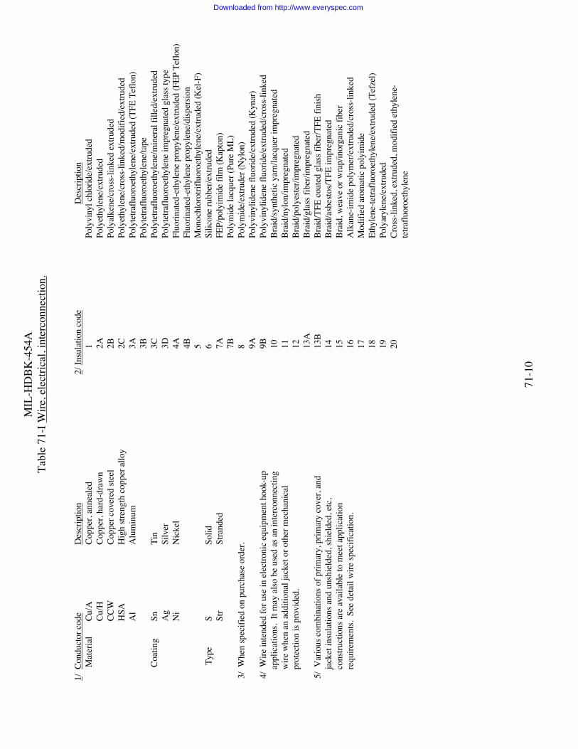
MIL
-HD
BK-4
54A
Tabl
e 71
-I W
ire, e
lect
rical
, int
erco
nnec
tion.
71-1
0
1/ C
ondu
ctor
cod
eD
escr
iptio
n 2/
Insu
latio
n co
de
Des
crip
tion
Mat
eria
lCu
/A
Copp
er, a
nnea
led
1Po
lyvi
nyl c
hlor
ide/
extru
ded
Cu/H
Co
pper
, har
d-dr
awn
2A
Poly
ethy
lene
/ext
rude
dC
CW
Co
pper
cov
ered
stee
l
2B
Poly
alke
ne/c
ross
-link
ed e
xtru
ded
HSA
H
igh
stren
gth
copp
er a
lloy
2C
Poly
ethy
lene
/cro
ss-li
nked
/mod
ified
/ext
rude
dA
l
Alu
min
um
3A
Po
lyte
traflu
oroe
thyl
ene/
extru
ded
(TFE
Tef
lon)
3B
Po
lyte
traflu
oroe
thyl
ene/
tape
Coat
ing
Sn
Ti
n
3C
Po
lyte
traflu
oroe
thyl
ene/
min
eral
fille
d/ex
trude
dA
g
Silv
er
3D
Poly
tetra
fluor
oeth
ylen
e im
preg
nate
d gl
ass t
ype
Ni
N
icke
l
4A
Fl
uorin
ated
-eth
ylen
e pr
opyl
ene/
extru
ded
(FEP
Tef
lon)
4B
Fl
uorin
ated
-eth
ylen
e pr
opyl
ene/
disp
ersio
n5
Mon
ochl
orot
riflu
oroe
thyl
ene/
extru
ded
(Kel
-F)
Typ
eS
Solid
6
Si
licon
e ru
bber
/ext
rude
dSt
r
Stra
nded
7A
FEP/
poly
imid
e fil
m (K
apto
n)7B
Poly
mid
e la
cque
r (Pu
re M
L)
3/
Whe
n sp
ecifi
ed o
n pu
rcha
se o
rder
.
8
Poly
mid
e/ex
trude
r (N
ylon
)
9A
Po
lyvi
nylid
ene
fluor
ide/
extru
ded
(Kyn
ar)
4
/ W
ire in
tend
ed fo
r use
in e
lect
roni
c eq
uipm
ent h
ook-
up
9B
Poly
viny
liden
e flu
orid
e/ex
trude
d/cr
oss-
linke
d
a
pplic
atio
ns.
It m
ay a
lso b
e us
ed a
s an
inte
rcon
nect
ing
10
Brai
d/sy
nthe
tic y
arn/
lacq
uer i
mpr
egna
ted
wire
whe
n an
add
ition
al ja
cket
or o
ther
mec
hani
cal
11
Brai
d/ny
lon/
impr
egna
ted
pro
tect
ion
is pr
ovid
ed.
12
Br
aid/
poly
este
r/im
preg
nate
d
13A
Br
aid/
glas
s fib
er/im
preg
nate
d
5/
Var
ious
com
bina
tions
of p
rimar
y, p
rimar
y co
ver,
and
13
B
Br
aid/
TFE
coat
ed g
lass
fibe
r/TFE
fini
sh
j
acke
t ins
ulat
ions
and
uns
hiel
ded,
shie
lded
, etc
,
14
Br
aid/
asbe
stos/T
FE im
preg
nate
d
c
onstr
uctio
ns a
re a
vaila
ble
to m
eet a
pplic
atio
n
15
Brai
d, w
eave
or w
rap/
inor
gani
c fib
er
r
equi
rem
ents.
See
det
ail w
ire sp
ecifi
catio
n.
16
A
lkan
e-im
ide
poly
mer
/ext
rude
d/cr
oss-
linke
d
17
M
odifi
ed a
rom
atic
pol
yim
ide
18
Ethy
lene
-tetra
fluor
oeth
ylen
e/ex
trude
d (T
efze
l)
19
Po
lyar
ylen
e/ex
trude
d
20
Cr
oss-
linke
d, e
xtru
ded,
mod
ified
eth
ylen
e-
te
traflu
oroe
thyl
ene
Downloaded from http://www.everyspec.com

MIL
-HD
BK-4
54A
Tabl
e 71
-I W
ire, e
lect
rical
, int
erco
nnec
tion.
71-1
1
Downloaded from http://www.everyspec.com

MIL
-HD
BK-4
54A
Tabl
e 71
-II W
ire, e
lect
rical
, int
erco
nnec
tion.
71-1
2
Cond
ucto
rSh
ield
bra
id 3
/Ja
cket
3/
Basic
No
Spec
Basic
Wire
ofV
olts
Stra
nd S
trand
% C
over
-no
.Ti
tleSp
ecs
cond
RM
STe
mp
2/m
ater
ial
coat
ing
age
Mat
eria
l 1/
Type
Rem
arks
MIL
-C-
3432
Cabl
e (P
ower
and
Spec
ial
(Pur
pose
)and
Wire
, Ele
c-tri
cal (
300&
600V
)
-W-3
43 &
Insu
latio
nU
nlim
ited
and
mix
edsiz
es
300
& 6
00-4
0°C
to+6
5°C
or-5
5°C
to+7
5°C
Non
e or
Copp
erTi
n 8
5St
yren
ebu
tadi
ene
Rubb
er,
chlo
ropr
ene
rubb
er,
ethy
lene
-
Extru
ded
&V
ulca
nize
d
4/ 5
/pr
opyl
ene
rubb
er,
ethy
lene
-pr
opyl
ene-
die
nne
rubb
er,
poly
uret
hane
ther
mop
lasti
cel
esto
mer
or
natu
ral r
ubbe
rM
IL-C
-70
78Ca
ble,
Ele
ctric
Aer
o Sp
ace
Veh
icle
M50
86/1
M50
86/2
M50
86/3
2-7
1-7
1-7
600
105°
CCo
pper
Copp
erTi
nTi
n
Non
ePo
lyam
ide
(Nyl
on)
Extru
ded
or
Impr
egba
ird(a
)27
500
M22
759/
12M
2275
9-23
1-7
1-7
260°
C26
0°C
Copp
erCo
pper
Nic
kel
Nic
kel
85 85(a
)(b
)Ex
trude
dex
trude
d or
tape
Fluo
rinat
ed ethy
lene
M81
044/
91-
710
0°C
Copp
erTi
n85
Poly
viny
liden
eflu
orid
eEx
trude
dpr
opyl
ene(
b)M
8138
1/8
2-7
200°
CPo
lyte
tra-
/10
and
/14
1-7
200°
CCo
pper
Nic
kel
85
FEP/
poly
imid
eFi
lm T
ape
fluor
oeth
ylen
eM
8138
1/11
2-7
200°
CM
8138
1/12
1-7
150°
CCo
pper
Tin
85FE
P/po
lyim
ide
Film
Tap
e
M81
381/
131-
720
0°C
Copp
erN
icke
l85
MIL
-C-
Cabl
eM
IL-C
-17
2-78
600
-53°
C to
Copp
erTi
n80
Shea
th P
oly-
Extru
ded
&Se
e13
777
Spec
ial
-W-3
43+7
1°C
Chlo
ropr
ene
vulc
aniz
edN
ote
7Pu
rpos
eEl
ectri
cal
AST
M A
580
&In
sula
tion
6/Pr
imar
yIn
sula
tion
Extru
ded
Poly
ethy
lene
Downloaded from http://www.everyspec.com

MIL
-HD
BK-4
54A
Tabl
e 71
-II W
ire, e
lect
rical
, int
erco
nnec
tion.
71-1
3
Cond
ucto
rSh
ield
bra
id 3
/Ja
cket
3/
Basic
No
Spec
Basic
Wire
ofV
olts
Stra
nd S
trand
% C
over
-no
.Ti
tleSp
ecs
cond
RM
STe
mp
2/m
ater
ial
coat
ing
age
Mat
eria
l 1/
Type
Rem
arks
MIL
-C-
2464
0Ca
ble,
Elec
trica
l,Li
ght w
eigh
tfo
r shi
p bo
ard
use
MIL
-W-8
1044
2-77
pai
r60
015
0°C
Copp
erTa
pe T
inne
d85
Cros
slink
edPo
lyal
kene
,Cr
ossli
nked
Alk
anei
mid
epo
lym
er, o
rPo
lyar
ylen
e
Extru
ded
MIL
-C-
Cabl
e Sp
ecia
lM
IL-C
-17
2-36
Var
ious
Not
spec
Copp
erTi
n, S
ilver
85Sh
eath
of
Flex
ible
2707
2Pu
rpos
e,El
ectri
cal,
Mul
ti-co
nduc
tor
M16
878/
1M
1687
8/2
M16
878/
3M
1687
8/4
M16
878/
5M
1687
8/6
M16
878/
10M
1687
8/13
600
1000
3000
600
1000
250
600
250
105°
C10
5°C
105°
C20
0°C
200°
C20
0°C
75°C
200°
C
PVC,
poly
ethy
lene
,po
lych
loro
pre
ne,
poly
amid
e,TF
E- T
eflo
n, o
rFE
P- T
eflo
n
mul
ticon
duct
orca
ble
for
use
inpr
otec
ted
, wire
way
s,in
stru-
men
tra
cks,
and
cond
uit,
Poly
-et
hyle
neja
ck- e
ted
cabl
esu
itabl
efo
run
derw
ater
or
dire
ctbu
rial
Downloaded from http://www.everyspec.com

MIL
-HD
BK-4
54A
Tabl
e 71
-II W
ire, e
lect
rical
, int
erco
nnec
tion.
71-1
4
Cond
ucto
rSh
ield
bra
id 3
/Ja
cket
3/
Basic
No
Spec
Basic
Wire
ofV
olts
Stra
nd S
trand
% C
over
-no
.Ti
tleSp
ecs
cond
RM
STe
mp
2/m
ater
ial
coat
ing
age
Mat
eria
l 1/
Type
Rem
arks
Not
e: M
IL-C
-270
72 a
pplic
able
det
ail s
peci
ficat
ion
shee
ts co
ntro
l mat
eria
ls fo
r eac
h sp
ecifi
c ca
ble
conf
igur
atio
n.
appl
icat
ion
s onl
y.M
1687
8/6
and
/13
not
for
aero
spac
e appl
icat
ion
sM
IL-
DTL
-Ca
ble,
MIL
-W-8
777
1-7
600
200°
CV
ario
usV
ario
us85
Var
ious
Brai
ded
2750
0El
ectri
cal,
MIL
-W-2
2759
1-7
Var
ious
Var
ious
Var
ious
Var
ious
85V
ario
usEx
trude
dSh
ield
ed a
ndU
nshi
elde
d,or
Bra
ided
Aer
ospa
ceM
IL-W
-250
381-
760
026
0°C
Var
ious
Var
ious
85TF
E co
ated
Brai
ded
glas
s fib
erM
IL-W
-810
441-
760
015
0°C
Var
ious
Var
ious
85V
ario
usEx
trude
dM
IL-
DTL
-813
811-
760
0V
ario
usV
ario
usV
ario
us85
Var
ious
Tape
For
gene
ral
aero
spac
e fligh
tve
hicl
eap
plic
ati
ons
MIL
-C-
Cabl
e,M
IL-W
-168
782-
360
0-4
0°C
toN
one
orTi
n,90
Non
eEx
trude
d55
021
Twist
ed P
airs
to+1
05°C
Copp
erSi
lver
PVC,
& T
riple
s,10
00or
-65°
Cor
Nic
kel
Nyl
onIn
tern
alto
+20
0°C
TFE-
Teflo
nEx
trude
dH
ooku
p,or
Tap
eG
ener
alSp
ecifi
catio
nfo
r
1/ P
olye
ster -
Pol
yeth
ylen
e Ter
epht
hala
te5/
Ava
ilabl
e in
thre
e cl
assif
icat
ions
:TF
E-Te
flon
- Pol
ytet
raflu
oroe
thyl
ene
PVC
- Pol
yvin
yl c
hlor
ide
(Not
to b
e us
ed in
Clas
s L -
Ligh
t Dut
y - t
o w
ithsta
nd se
vere
flex
ing
and
airb
orne
app
licat
ions
)
frequ
ent m
anip
ulat
ion
KEL
-F -
Poly
mon
ochl
orot
riblu
oroe
thyl
ene
FEP-
Teflo
n - F
luor
inat
ed e
thyl
ene
prop
ylen
eC
lass
M -
Med
ium
Dut
y - t
o w
ithsta
nd se
vere
flex
ing
PVF
- Pol
yvin
ylid
ene
fluor
ide
a
nd m
echa
nica
l abu
se(c
ontin
ued)
Downloaded from http://www.everyspec.com

MIL
-HD
BK-4
54A
Tabl
e 71
-II W
ire, e
lect
rical
, int
erco
nnec
tion.
71-1
5
2/ S
ee a
pplic
able
det
ail s
peci
ficat
ion
shee
t for
Clas
s H -
Hea
vy D
uty
- to
with
stand
seve
re fl
exin
g an
dte
mpe
ratu
re li
mita
tions
.
mec
hani
cal a
buse
and
abi
lity
to w
ithsta
nd
seve
re se
rvic
e im
pact
s suc
h as
to b
e ru
n ov
er
by
tank
s or t
ruck
s3/
See
app
licab
le d
etai
l spe
cific
atio
n sh
eet f
or6/
See
app
licab
le d
etai
l spe
cific
atio
n sh
eet f
or m
echa
nica
lm
ater
ials
cont
rol o
f spe
cific
cab
le c
onfig
urat
ions
test
requ
irem
ents
for c
old
bend
torq
ue,
impa
ct b
end,
and
twist
.
4/ A
lthou
gh th
e sp
ecifi
catio
n do
es n
ot li
mit
the
7/ F
or u
se u
nder
abu
sive
mec
hani
cal c
ondi
tions
and
whe
renu
mbe
r of c
ondu
ctor
s in
a ca
ble,
the
size,
re
sista
nce
to w
eath
er, o
il an
d oz
one
are
requ
irem
ents.
wei
ght,
and
flexi
bilit
y ar
e de
term
inin
g fa
ctor
s.
Downloaded from http://www.everyspec.com

MIL-HDBK-454A
72-1
GUIDELINE 72
SUBSTITUTABILITY
1. Purpose. This guideline establishes criteria for the selection and application of substitute parts.
2. Applicable Documents
MIL-STD-973 Configuration ManagementMIL-HDBK-983 Substitution List for MicrocircuitsEIA-IS-649 Configuration Management
3. Definitions. Not applicable.
4. General Guidelines.
4.1 Military parts. Substitution of parts covered by military specifications and standards thatinclude substitutability or supersession information is acceptable. This type substitution does notrequire submission of engineering change proposals, deviations, or waivers in accordance withMIL-STD-973.
4.2 Commercial parts. When the equipment design specifies a commercial part, a militaryspecification part may be substituted when the form, fit and functional characteristics of themilitary part are equal to or better than those of the specified commercial part under equivalentenvironmental conditions. Applicable microcircuits are listed in MIL-HDBK-983. Othersubstitutions are subject to applicable configuration control procedures of MIL-STD-973.
4.3 Unavailable parts. When the equipment design specifies a part that is unavailable, asubstitute part which meets the form, fit and functional characteristics of the specified part may besubstituted after approval is obtained from the applicable procuring activity. Applicablemicrocircuits are listed in MIL-HDBK-983. Other substitutions are subject to the applicableconfiguration control procedures of MIL-STD-973.
4.4 Initial qualification/reliability demonstration. Substitute parts with quality/reliabilitycharacteristics superior to those specified in the parts list should not be used in equipment to besubjected to initial qualification or demonstration tests.
4.5 Other Guidance. Additional information can be found in EIA-IS 649.
5. Detail Guidelines. Not applicable.
Downloaded from http://www.everyspec.com

MIL-HDBK-454A
73-1
GUIDELINE 73
STANDARD ELECTRONIC MODULES
1. Purpose. This guideline establishes criteria for the selection and application of StandardElectronic Modules (SEM).
2. Applicable Documents.
MIL-STD-1389 Design Requirements for Standard Electronic ModulesMIL-HDBK-246 Program Managers Guide for the Standard Electronic Modules
Program
3. Definitions. Not applicable.
4. General Guidelines.
4.1 Application. Requirements for the design and application of SEMs should be inaccordance with MIL-STD-1389.
5. Detail Guidelines.
5.1 Program and Acquisition Managers. Guidance for program and acquisition managers asto the applicability of SEMs for specific system/equipment acquisitions is provided inMIL-HDBK-246.
Downloaded from http://www.everyspec.com

MIL-HDBK-454A
74-1
GUIDELINE 74
GROUNDING, BONDING, AND SHIELDING
1. Purpose. This guideline establishes grounding, bonding, and shielding interface criteria forinstallation of electronic equipment.
2. Applicable Documents.
MIL-STD-188-124 Grounding, Bonding, and Shielding for Common LongHaul/Tactical Communication Systems Including Ground BasedCommunications-Electronics Facilities and Equipments
MIL-STD-464 Interface Standard for Electromagnetic Environmental EffectsRequirements for Systems
MIL-STD-1310 Shipboard Bonding, Grounding, and Other Techniques forElectromagnetic Compatibility and Safety
MIL-STD-1542 Electromagnetic Compatibility (EMC) and GroundingRequirements for Space System Facilities
MIL-HDBK-419 Ground, Bonding, and Shielding for Electronic Equipments andFacilities
MIL-HDBK-1857 Grounding, Bonding, and Shielding Design Practices
3. Definitions. Not applicable.
4. General Guidelines.
4.1 Provisions. Grounding, bonding, and shielding provisions should be incorporated intoequipment design, as necessary, to enable installation of equipment into the applicable platform orfacility. The grounding, bonding, and shielding installation and interface requirements arespecified in the following documents:
Aerospace ground support facilities MIL-STD-464Aircraft and space vehicles MIL-STD-464Ground telecommunications C-E equipment MIL-STD-188-124Shipboard equipment MIL-STD-1310Ground space systems facilities MIL-STD-1542Other Army ground equipment MIL-HDBK-1857
4.2 Other Guidance. Guidance for grounding, bonding, and shielding may be found inMIL-HDBK-419.
5. Detail Guidelines. Not applicable.
Downloaded from http://www.everyspec.com

MIL-HDBK-454A
75-1
GUIDELINE 75
ELECTROSTATIC DISCHARGE CONTROL
1. Purpose. This guideline offers guidance regarding the handling and control of electronicparts and assemblies that are susceptible to damage or degradation from electrostatic discharge.Guidelines for the establishment and implementation of an Electrostatic Discharge (ESD) controlprogram in accordance with MIL-STD-1686 may be directly specified in the contract orequipment specification.
2. Applicable Documents.
MIL-STD-883 Test Method Standard, MicrocircuitsMIL-STD-1686 Electrostatic Discharge Control Program for Electronic Parts,
Assemblies, and Equipment (excluding electrically initiatedexplosive devices), Standard Practice for
MIL-HDBK-263 Electrostatic Discharge Control Handbook for Protection ofElectrical and Electronic Parts, Assemblies, and Equipment(excluding electrically initiated explosive devices)
3. Definitions. Definitions of applicable terminology may be found in MIL-STD-883,MIL-STD-1686, and MIL-HDBK-263.
4. General Guidelines. Not applicable.
5. Detail Guidelines.
5.1 ESD control program. MIL-STD-1686 provides the guidelines for the establishment,implementation, and monitoring of an ESD control program, including identification ofElectrostatic Discharge Sensitive (ESDS) items, classification of ESD sensitivity levels, controlprogram elements, extent of program element applicability to each acquisition, protectivemeasures to be employed in equipment design, handling, storage, and packaging of ESDS items,protected work areas, personnel training, ESD audits and program reviews, and tailoring.Appendix A of MIL-STD-1686 provides the criteria and procedure for classifying ESDS parts bytest. Appendix B of MIL-STD-1686 identifies and classifies ESDS items. MIL-HDBK-263provides guidance for the establishment and implementation of an ESD control program inaccordance with MIL-STD-1686.
5.2 General guidelines for an ESD control program. Any program designed for the preventionof ESD damage to ESDS parts and assemblies should be based on the following considerations:
a. Identification of ESDS parts and assemblies and determination of sensitivity.
b. Minimization of static charge generation.
Downloaded from http://www.everyspec.com

MIL-HDBK-454A
75-2
c. Reduction of stored charges (grounding).
d. Isolation of ESDS parts (Faraday shielding and line transient protection).
e. Proper handling, storage, and transportation of ESDS parts and assemblies.
f. Personnel training and certification.
g. Protected work areas.
Downloaded from http://www.everyspec.com

MIL-HDBK-454A
76-1
GUIDELINE 76
FIBER OPTICS
1. Purpose. This guideline establishes the criteria for the selection, application and testing offiber optic material, devices and accessories.
2. Applicable Documents.
MIL-C-22520/10 Crimping Tool, Terminal, HandMIL-S-24623 Splice, Fiber Optic Cable, General Specification for (Metric)MIL-S-24725 Switches, Fiber Optic, Shipboard, Electrical Nonlatching, Bypass,
Multimode Cable, Standalone (Metric)MIL-I-24728 Interconnection Box, Fiber Optic, Metric, General Specification forMIL-M-24791 Module, Fiber Optic, Transmitter or Receiver, Digital, General
Specification forMIL-M-24792 Adhesive, Epoxy, Two Part, Fiber OpticMIL-M-24793 Adhesive UV Curable, One Part Fiber OpticsMIL-M-24794 Material, Index Matching, Fiber OpticsMIL-C-28876 Connectors, Fiber Optic, Environment Resisting (for Navy Shipboard
Applications)MIL-T-29504 Termini, Fiber Optic Connector, RemovableMIL-PRF-49291 Fiber, Optical, General Specification forMIL-C-49292 Cable Assembly, Nonpressurized, General Specification forMIL-I-81969 Installing and Removal Tools, Electrical Contact, General Specification
forMIL-C-83522 Connectors, Fiber Optic, Single Terminus, General Specification forMIL-K-83525 Kit, Portable Optical Microscope, Militarized, 200X Magnification for
Field Inspection of Optical FibersMIL-C-83526 Connector, Fiber Optic, Circular, Environment Resisting,
Hermaphroditic, General Specification forMIL-M-85045 Cables, Fiber Optics, (Metric), General Specification forMIL-STD-188-111 Subsystem Design and Engineering Standards for Common Long Haul
and Tactical Fiber Optics CommunicationsMIL-STD-790 Established Reliability and High Reliability Qualified Products List
(QPL) Systems for Electronic and Fiber Optic Parts SpecificationsDOD-STD-1678 Fiber Optic Test Methods and InstrumentationMIL-STD-2163 Insert Arrangements for MIL-C-28876 Connectors, Fiber Optic,
Circular, Plug and Receptacle style, Multiple Removable TerminiMIL-HDBK-415 Design Handbook for Fiber Optic Communications SystemsEIA/TIA-440 Fiber Optic TerminologyEIA/TIA-587 Fibers, Optical Graphic Symbols
Downloaded from http://www.everyspec.com

MIL-HDBK-454A
76-2
3. Definitions.
3.1 Terminology. Definitions of terminology used in fiber optics technology should be ascontained in EIA/TIA-440.
4. General Guidelines.
4.1 Symbology. Graphic symbols for fiber optic parts for use on engineering drawings,specifications, etc, should be as contained in EIA/TIA-587.
4.2 Fiber Dimensions. Dimensions for optical fibers should be as specified inMIL-PRF-49291.
4.3 System and subsystem design. Fiber optic system and subsystem designs should be inaccordance with the criteria specified in MIL-STD-188-111 (see 5.1 also).
4.4 Test procedures. Standardized test procedures for fiber optic components should beas specified in DOD-STD-1678.
4.5 Splices. Fiber optic splices should conform to MIL-S-24623.
4.6 Cable assemblies. Cable assemblies should conform to MIL-C-49292.
4.7 Connectors. Fiber optic connectors should conform to MIL-C-28876,MIL-C-83522, MIL-C-83526. Insert arrangements for MIL-C-28876 connectors should conformto MIL-STD-2163. Removable terminals for fiber optic connectors should conform toMIL-T-29504.
4.8 Interconnection boxes. Fiber optic interconnection boxes should conform toMIL-I-24728.
4.9 Switches. Fiber optic switches should conform to MIL-S-24725.
4.10 Tools and inspection equipment. Fiber optic tools, inspection equipment, and relatedkits should conform to MIL-I-81969, MIL-K-83525, and MIL-C-22520/10.
4.11 Transmitters and Receivers. Fiber optic transmitters and receivers shouldconform to MIL-M-24791.
4.12 Adhesives.
4.12.1 Two part epoxy adhesives should conform to MIL-A-24792.
4.12.2 UV curable adhesives should conform to MIL-A-24793.
Downloaded from http://www.everyspec.com

MIL-HDBK-454A
76-3
4.13 Materials. Index matching materials should conform to MIL-M-24794.
4.14 Cables. Fiber Optic cables should conform to MIL-C-85045.
5. Detail Guidelines.
5.1 Design guides. Fiber optic system design guide information is available inMIL-HDBK-415.
5.2 Product assurance program. When a requirement exists for the implementation of afiber optic product assurance program, refer to MIL-STD-790.
Downloaded from http://www.everyspec.com
MIL-HDBK-454A
77-1
GUIDELINE 77
INTEGRATED DIAGNOSTICS
1. Purpose. This guideline establishes a design process for integrating all elements whichconstitute a weapon system's diagnostic capability. Engineering analyses, qualitative andquantitative requirements, design analysis, demonstration and maturation requirements may bespecified in the contract or system/equipment specification, as appropriate.
2. Applicable Documents.
MIL-STD-1814 Integrated DiagnosticsMIL-HDBK-470 Maintainable Programs for System and EquipmentMIL-HDBK-502 Acquisition LogisticsMIL-HDBK-2165 Testability Handbook Systems and EquipmentsAFGS-87256 AF Guide Specification on Integrated DiagnosticsASTM F 1166 Standard Practices for Human Engineering Design for Marine Systems,
Equipment, and FacilitiesEIA-IS-632 Process for Engineering a System
3. Definitions.
3.1 Integrated diagnostics process. Integrated diagnostics is defined as a structuredprocess which maximizes the effectiveness of diagnostics by integrating pertinent elements, suchas; testability, automatic and manual testing, training, maintenance aiding, and technicalinformation. Integrated diagnostics provides a cost-effective capability to detect andunambiguously isolate all faults known or expected to occur in weapon systems and equipmentand to satisfy weapon system mission requirements. This emphasis on the design and acquisitionof the diagnostic capability is required because this capability tends to become fractionated.MIL-HDBK-2165 is the overall document for testability. However, because it is amultidisciplined process, reference to other portions of military documents that may be invoked ormay be cited directly are; MIL-HDBK-470, MIL-HDBK-471, EIA-IS-632, MIL-STD-1814,AFGS-87256, and ASTM F 1166.
4. General Guidelines. Not applicable.
5. Detail Guidelines.
5.1 Test Provisions.
5.1.1 Testability programs. When specified by the procuring activity a testability programshould be implemented by guidance found in MIL-HDBK -2165.
Downloaded from http://www.everyspec.com

MIL-HDBK-454A
77-2
5.1.2 Built-in-test devices. Built-in test devices should maintain their accuracy under alloperating conditions required by the equipment under test. These devices should be providedwith connections or access for their operational checkouts or calibration.
5.1.3 Test provisions. Equipment which is required to be tested by on-line Automatic TestEquipment (ATE) should provide test points.
5.1.4 Test cables. Test cables and extender cards should be provided and fitted withconnectors to allow removable subassemblies to be electrically reconnected for maintenance.
5.1.5 External test points. Protection should be provided in the test point circuitry toprevent equipment damage caused by the external grounding of test points.
5.1.6 Failure effect. Provisions for testing should be designed that any failure of built-intest devices will not degrade equipment operation or cause equipment shut down.
5.2 Safety criteria. Safety criteria should be applied during equipment hardware design,selection, end construction to eliminate or control hazards that could cause injury to personnelduring transportation, storage, installation, operation, maintenance or disposal, or damage toequipment or property.
Downloaded from http://www.everyspec.com
MIL-HDBK-454A
78-1
GUIDELINE 78
PRODUCIBILITY
1. Purpose. This guideline establishes criteria for producibility which should be considered when preparingcontractual documents. Producibility program tasks, quantitative requirements, verification or demonstrationrequirements may be directly specified in the contract or the system and/or equipment specification, asappropriate.
2. Applicable Documents.
DoD 4245.7M Transition from Development to ProductionNAVSO P-3679 Producibility Measurement GuidelinesNAVSO P-6071 Best PracticesMIL-HDBK-727 Design Guidance for Producibility
3. Definitions. Not applicable.
4. General Guidelines. Not applicable.
5. Detail Guidelines.
5.1 Producibility program. Producibility engineering and planning tasks aimed at preventing, detecting, andcorrecting manufacturability design deficiencies and providing producibility related information essential toacquisition, operation, and support management should be included in contract requirements with the objectiveof establishing and maintaining an efficient producibility program according to program phase. NAVSO P-3679is the overall program document for the subject. The successful creation and management of a producibilityprogram is detailed in section 2 of NAVSO P-3679.
5.2 Producibility measurement. Producibility measurement and assessment tools are a critical part ofinsuring a product is ready for production. Sections 3 and 4 of NAVSO P-3679 give two industry examples ofmeasurement and assessment tools.
5.3 Quantitative producibility. Quantitative producibility requirements and verification or demonstrationrequirements should be established as appropriate to program phase. Producibility measurement is an essentialpart of the design process which can determine the probability of successful production. Minimal tailoringshould be required when NAVSO P-3679 is applied to a program. Other producibility documents which may becited directly as a basis for contract requirements include DoD 4245.7M, NAVSO P-6071, and MIL-HDBK-727for guidance only.
Downloaded from http://www.everyspec.com

MIL-HDBK-454AINDEX
1
INDEX OF APPLICABLE DOCUMENTS
Document Guideline
SPECIFICATIONS
Federal
L-P-516............................... 11,26V-T-285 .............................. 44V-T-295 .............................. 44W-B-133 ............................. 27W-S-896 ............................. 58FF-B-171 ............................ 6FF-B-187 ............................ 6FF-N-836 ............................ 12FF-R-556 ............................ 12FF-S-85............................... 12FF-S-86............................... 12FF-S-92............................... 12FF-S-200............................. 12FF-S-210............................. 12FF-W-84 ............................. 12FF-W-92 ............................. 12FF-W-100 ........................... 12QQ-W-343.......................... 20,66,71VV-P-236 ........................... 43ZZ-R-765............................ 26MMM-A-121...................... 23MMM-A-132...................... 23MMM-A-134...................... 23MMM-A-138...................... 23MMM-A-181...................... 23MMM-A-189...................... 23MMM-A-1617.................... 23MMM-A-1931.................... 23
Military
MIL-PRF-1 ......................... 29MIL-C-17............................ 65,66,71MIL-DTL-85....................... 53MIL-T-152.......................... 4,69MIL-DTL-287..................... 53MIL-W-530 ........................ 44MIL-C-572.......................... 44MIL-I-631........................... 11,69MIL-J-641........................... 10MIL-P-642 .......................... 10MIL-T-713.......................... 69MIL-S-1222 ........................ 12MIL-I-1361......................... 40MIL-PRF-2105 ................... 43
MIL-PRF-3098....................38MIL-PRF-3150....................43MIL-I-3158 .........................11,69MIL-I-3190 .........................11,69MIL-C-3432 ........................66,71MIL-T-3530 ........................44MIL-S-3786.........................58MIL-L-3661 ........................50MIL-L-3890 ........................65MIL-A-3920........................23MIL-F-3922.........................53MIL-S-3928.........................53MIL-A-3933........................53MIL-S-3950.........................58MIL-D-3954........................53MIL-DTL-3970 ...................53MIL-W-4088.......................44MIL-DTL -5015 ..................10MIL-W-5086.......................71MIL-R-5757........................57MIL-F-5591.........................12MIL-R-5674 ........................12MIL-PRF-6085....................43MIL-PRF-6086....................43MIL-PRF-6106....................57MIL-DTL-6363 ...................50MIL-S-6807.........................58MIL-M-7793 .......................51MIL-R-7885 ........................12MIL-L-7961 ........................50MIL-PRF-8516....................47MIL-B-8565 ........................27MIL-W-8777.......................71MIL-PRF-8805....................58MIL-B-8831 ........................12MIL-B-8942 ........................6MIL-B-8943 ........................6MIL-B-8948 ........................6MIL-C-9074 ........................44MIL-S-9395.........................58MIL-S-9419.........................58MIL-S-12285.......................58MIL-PRF-12883..................60MIL-S-13484.......................58MIL-S-13572.......................41MIL-S-13623.......................58MIL-C-13777 ......................71MIL-DTL-15024 .................67MIL-L-15098 ......................50MIL-I-15126 .......................11MIL-S-15291.......................58MIL-C-15370 ......................53MIL-T-15659 ......................19MIL-L-15719 ......................43
MIL-PRF-15733 ................. 70MIL-S-15743 ...................... 58MIL-S-16032...................... 58MIL-M-16034..................... 51MIL-M-16125..................... 51MIL-F-16552 ...................... 52MIL-W-16878 .................... 20,66,71MIL-I-16923....................... 47MIL-M-17059..................... 46MIL-M-17060..................... 46MIL-I-17205....................... 11MIL-L-17331...................... 43MIL-PRF-17672 ................. 43MIL-B-18013...................... 27MIL-PRF-18240 ................. 12MIL-C-18277...................... 53MIL-N-18307 ..................... 67MIL-S-18396 ...................... 58MIL-D-18576 ..................... 53MIL-I-19166....................... 11MIL-PRF-19500 ................. 30,50MIL-C-21097...................... 10MIL-S-21604...................... 58MIL-I-22076....................... 11,69MIL-I-22129....................... 11MIL-A-22397 ..................... 23MIL-S-22432 ...................... 56MIL-S-22473 ...................... 12MIL-C-22520/10 ................ 76MIL-DTL-22641................. 53MIL-PRF-22710 ................. 58MIL-W-22759 .................... 20,66,71MIL-S-22820 ...................... 56MIL-T-22821...................... 56MIL-PRF-22885 ................. 58MIL-C-22931...................... 65MIL-F-22978 ...................... 12MIL-C-22992...................... 10MIL-B-23071...................... 46,52MIL-I-23264....................... 11MIL-L-23398...................... 43MIL-PRF-23586 ................. 47MIL-T-23648...................... 33MIL-C-23806...................... 65MIL-PRF-23827 ................. 43MIL-P-23971...................... 53MIL-M-24041..................... 47MIL-DTL-24044................. 53MIL-S-24067...................... 53MIL-I-24092....................... 11MIL-G-24139 ..................... 43MIL-A-24179 ..................... 23MIL-I-24204....................... 11MIL-DTL-24211................. 53
Downloaded from http://www.everyspec.com

MIL-HDBK-454AINDEX
2
MIL-PRF-24236 ................. 58MIL-R-24243...................... 12MIL-S-24251 ...................... 60MIL-S-24317...................... 58MIL-I-24391....................... 11DOD-G-24508.................... 43MIL-B-24541...................... 27MIL-S-24623 ...................... 76MIL-C-24640...................... 66,71MIL-C-24643...................... 66,71MIL-S-24725 ...................... 76MIL-I-24728....................... 76MIL-I-24768....................... 11,26MIL-M-24791..................... 76MIL-M-24792..................... 76MIL-M-24793..................... 76MIL-M-24794..................... 76MIL-W-25038 .................... 71MIL-PRF-25879 ................. 53MIL-C-27072...................... 66,71MIL-W-27265 .................... 44MIL-DTL-27500................. 71MIL-S-28714...................... 58MIL-D-28728 ..................... 28MIL-PRF-28750 ................. 57MIL-PRF-28776 ................. 57MIL-PRF-28788 ................. 58MIL-C-28790...................... 53MIL-I-28791....................... 53MIL-C-28806...................... 53MIL-M-28827..................... 58MIL-C-28830...................... 65MIL-M-28837..................... 53MIL-PRF-28861 ................. 70MIL-A-28875 ..................... 53MIL-C-28876...................... 76MIL-T-29504...................... 76MIL-B-29595...................... 27MIL-C-29600...................... 10MIL-PRF-31031 ................. 10MIL-PRF-38534 ................. 64MIL-PRF-38535 ................. 64MIL-DTL-38999................. 10MIL-PRF-39006/22 ............ 2MIL-PRF-39006/25 ............ 2MIL-PRF-39012 ................. 10MIL-PRF-39016 ................. 57MIL-PRF-39024 ................. 10MIL-DTL-39030................. 53MIL-L-46010...................... 43MIL-S-46049 ...................... 41MIL-A-46146 ..................... 23MIL-S-47314...................... 58MIL-PRF-49142 ................. 10MIL-PRF-49291 ................. 76
MIL-C-49292 ......................76MIL-PRF-49450..................27MIL-PRF-49471..................27MIL-C-55021 ......................66,71MIL-DTL-55041 .................53MIL-C-55116 ......................10MIL-T-55156 ......................19MIL-C-55302 ......................10MIL-PRF-55310..................38MIL-PRF-55339..................10MIL-S-55433.......................58MIL-T-55631 ......................14MIL-S-62300.......................58MIL-C-81021 ......................41MIL-W-81044.....................20,66,71MIL-PRF-81322..................43MIL-PRF-81329..................43MIL-DTL-81381 .................20,71MIL-I-81550 .......................47MIL-S-81551.......................58MIL-S-81746.......................56MIL-PRF-81757..................27MIL-I-81765 .......................11MIL-B-81793 ......................6MIL-W-81822.....................20MIL-S-81963.......................56,67MIL-I-81969 .......................76MIL-S-83502.......................60MIL-DTL-83503 .................10MIL-PRF-83504..................58MIL-C-83517 ......................10MIL-C-83522 ......................76MIL-K-83525......................76MIL-C-83526 ......................76MIL-PRF-83536..................57MIL-T-83721 ......................14MIL-C-83723 ......................10MIL-PRF-83726..................57MIL-DTL-83731 .................58MIL-DTL-83734 .................60MIL-I-85045 .......................76MIL-E-85082 ......................56MIL-S-85242.......................58MIL-S-85377.......................58MIL-F-85731.......................55MIL-D-87157......................68
STANDARDS
Federal
FED-STD-H28 ....................12
Military
MIL-STD-22....................... 13MIL-STD-108..................... 55,69MIL-STD-130..................... 67MIL-STD-188-111.............. 76MIL-STD-188-124.............. 74MIL-STD-196..................... 34,67MIL-HDBK-198 ................. 2MIL-STD-202..................... 3MIL-STD-276..................... 21MIL-STD-411..................... 67MIL-STD-464..................... 1,61,74MIL-STD-469..................... 61MIL-STD-681..................... 20MIL-STD-704..................... 25MIL-STD-710..................... 56MIL-STD-783..................... 67MIL-STD-790..................... 76MIL-STD-810..................... 4MIL-STD-883..................... 75MIL-STD-889..................... 15,16MIL-STD-973..................... 72MIL-STD-981..................... 14MIL-STD-1275................... 25MIL-STD-1285................... 67MIL-STD-1310................... 1,74MIL-STD-1311................... 29MIL-STD-1389................... 73MIL-STD-1399................... 25MIL-STD-1425................... 1MIL-STD-1472............... 1,36,50,62MIL-STD-1542................... 74DOD-STD-1578 ................. 27DOD-STD-1678 ................. 76MIL-STD-1686................... 75MIL-STD-1814................... 77MIL-STD-2036................... FWDMIL-STD-2163................... 76MIL-STD-2196(SH) ........... 76MIL-STD-13231................. 67MS25217 ............................ 27MS25471 ............................ 71MS27110 ............................ 71MS33557 ............................ 12MS35000 ............................ 27
HANDBOOKS
Military
MIL-HDBK-5 ..................... 13MIL-HDBK-103 ................. 64MIL-HDBK-216 ................. 53,65MIL-HDBK-217 .................…………………….35,37,38,39
Downloaded from http://www.everyspec.com

MIL-HDBK-454AINDEX
3
MIL-HDBK-225 ................. 56MIL-HDBK-231 ................. 56MIL-HDBK-246 ................. 73MIL-HDBK-251 ................. 52MIL-HDBK-263 ................. 75MIL-HDBK-411 ................. 25MIL-HDBK-415 ................. 76MIL-HDBK-419 ................. 74MIL-HDBK-470 ................. 54,77MIL-HDBK-472 ................. 54MIL-HDBK-502 ................. 77MIL-HDBK-505 ................. 7,8,36,67MIL-HDBK-660 ................. 53MIL-HDBK-691 ................. 23MIL-HDBK-727 ................. 78MIL-HDBK-730 ................. 13MIL-HDBK-781 ................. 35MIL-HDBK-965 ................. 22MIL-HDBK-983 ................. 72MIL-HDBK-1277 ............... 19MIL-HDBK-1547 ............... 7,18MIL-HDBK-1857 ............... 74MIL-HDBK-1861 ............... 17MIL-HDBK-2165 ............... 32, 77MIL-HDBK-11991 ............. FWD
OTHER GOVT DOCUMENTS
A-A-1936............................ 23A-A-3097............................ 23A-A-50197.......................... 44A-A-52094.......................... 44A-A-52401.......................... 6A-A-52414.......................... 6A-A-55485.......................... 60A-A-55524.......................... 40A-A-59125.......................... 19A-A-59313.......................... 12AFGS-87256....................... 77DOD 4245.7M.................... 78DOD 6050.5-M .................. 1DOD 6055.11 ..................... 110 CFR 20 .......................... 121 CFR 1000 - 1050 ........... 129 CFR 1910 .........................................1,4,11,23,26,43,44,47NTIA Manual ..................... 61NAVSO P-3679.................. 78NAVSO P-6071.................. 78TEOOO-AB-GTP-010........ 30,64QML-19500........................ 30QML-38534........................ 64QML-38535........................ 64QPL-1 ................................. 29
NON-GOVT DOCUMENTS
AGMA Specifications .........48AMI-BCI.............................67AMS-STD-1595..................13ANSI B93.1.........................49ANSI B93.2.........................49ANSI B93.3.........................49ANSI B93.4.........................49ANSI B93.5.........................49ANSI B93.6.........................49ANSI B93.7.........................49ANSI B93.8.........................49ANSI B93.9.........................49ANSI B93.10.......................49ANSI B93.11.......................49ANSI C95.1.........................1ANSI C95.2.........................1ANSI J-STD-001.................5ANSI N2.1 ..........................1ANSI Z136.1.......................1ANSI Z535.1.......................1ANSI Z535.2.......................1ANSI Z535.3.......................1ANSI Z535.4.......................1ANSI Z535.5.......................1ANSI/AIAA R-100 .............22ANSI/AWS A2.4 ................13ANSI/AWS A3.0 ................13ANSI/IPC-D-322 ................17ANSI/SAE J514 ..................49ANSI/SAE J518 ..................49ASME B1.1.........................12ASME B1.13M ...................12ASME B18.2.1....................12ASME B18.3.......................12ASME B18.6.3....................12ASME B18.6.7M ................12ASME B18.21.1..................12ASME B18.22.1..................12ASME B18.24.1..................12ASME B18.24.2..................12ASME B18.24.3..................12ASME B18.29.1..................12ASME Y14.38.....................67ASTM A29/A29M..............41ASTM A228/A228M..........41ASTM A313/A313M..........41ASTM A325........................12ASTM A354........................12ASTM A449........................12ASTM A490........................12
ASTM A682/A682M..........41
ASTM A684/A684M.......... 41ASTM B33 ......................... 71ASTM B122/B122M .......... 41ASTM B139/B139M .......... 41ASTM B151/B151M .......... 41ASTM B194 ....................... 41ASTM B196/B196M .......... 41ASTM B197/B197M .......... 41ASTM B206/B206M .......... 41ASTM B298 ....................... 20,66,71ASTM B522 ....................... 41ASTM D149 ....................... 45ASTM D495 ....................... 26ASTM D635 ....................... 3ASTM D1000 ..................... 3ASTM D1868 ..................... 45ASTM D3295 ..................... 11ASTM D4388 ..................... 11ASTM D4956 ..................... 67ASTM D5213 ..................... 26ASTM D5948 ..................... 26ASTM F872........................ 52ASTM F1166...................... 1,77AWS A2.4 .......................... 13AWS A3.0 .......................... 13AWS C3.4 .......................... 59AWS C3.5 .......................... 59AWS C3.6 .......................... 59AWS C3.7 .......................... 59AWS D1.1 .......................... 13EIA-297-A.......................... 10EIA-310-C .......................... 55EIA/TIA-440....................... 76EIA/TIA-587....................... 76EIA-632 .............................. 77EIA-IS-649 ......................... 72IEEE 200............................. 67NAS 498 ............................. 12NAS 547 ............................. 12NAS 1686 ........................... 12NAS 1687 ........................... 12NASM6812 ........................ 12NASM7838 ........................ 12NASM8814 ........................ 12NASM25027 ...................... 12NASM27384 ...................... 12NASM33522 ...................... 12NASM33540 ...................... 12NEMA C18.1M.................. 27NEMA RE 2 ....................... 11NFPA 70............................. 1,8NTIA Manual ..................... 61SAE ARP 1199................... 39SAE/AMS-A-8576 ............. 23SAE/AMS-A-25463 ........... 23
Downloaded from http://www.everyspec.com

MIL-HDBK-454AINDEX
4
SAE/AMS-W-6858 ............ 13SAE/AMS-STD-2175......... 21SAE/AMS-STD-2219......... 13SAE AS7928 ...................... 19,69SAE AS 8879 ..................... 12SAE AS13341 .................... 6SAE AS23190 .................... 69SAE AS 27212 ................... 19SAE AS39901 .................... 6SAE AS5440 ...................... 49SAE AS81934 .................... 6SAE AS81936 .................... 6SAE/AMS 2680.................. 13SAE/AMS 2681.................. 13SAE/AMS 3638.................. 11SAE/AMS 3653D............... 11SAE/AMS 3654B ............... 11SAE/AMS 3655A............... 11SAE/AMS 5121.................. 41SAE/AMS 5122.................. 41SAE J357............................ 27UL 94.................................. 3
Downloaded from http://www.everyspec.com

MIL-HDBK-454AINDEX
5
SUBJECT INDEX
Subject Guideline
Abbreviations...................... 67Access devices .................... 12Accessibility........................ 36Adapters Rf connector..................... 10 Waveguide ....................... 53Adhesives............................ 23Antiseize compound............ 12Arc-resistant materials........ 26Attenuators, rf ..................... 53Barriers, electrical ............... 1Batteries .............................. 27Bearing assemblies ............. 9Boards Discrete wiring................. 17 Printed wiring .................. 17Bolts.................................... 12Bonding Adhesive .......................... 23 Electrical .......................... 1, 74Brazing................................ 59Cabinets .............................. 55Cable, coaxial ..................... 65Cable, multiconductor Interconnection................. 71 Internal............................. 66Capacitors ........................... 2Carcinogens ........................ 1, 4, 11,23, 26, 43, 44, 47Cases................................... 55Castings .............................. 21Circuit breakers................... 8, 37Cleaning.............................. 9Clearance ............................ 9, 69Coaxial cable ...................... 65Coils.................................... 14Commercial parts................ 72Conformal coating .............. 17Connections Accessibility of ................ 36 Clamped........................... 69 Crimp............................... 69 Marking of ....................... 67 Soldered ........................... 5 Welded............................. 24 Wire Wrap ....................... 69Connectors Electrical .......................... 1, 10 Filter pin .......................... 10 Rf coaxial......................... 10
Bearings ...........................6Containment ........................9Controls...............................28 Insulation of......................1 Flexible shafts for .............28, 42Converters, rotary power .....46Cooling................................52Corona prevention ...............45Corrosion protection............15, 16Couplers, directional ...........53Creepage distance................69Crystal units ........................38Derating...............................18Desiccants ...........................31, 55Devices, microelectronic......64Devices, semiconductor.......30Diagnostics, integrated........77Dial mechanisms, tuning.....42Dials, control .......................28Discharging devices ............1Displays...............................68Dissimilar metals ................16Dynamotors .........................46Electrical Breakdown .......................45 Connections…………..5,10,24,69 Filters ...............................10, 70 Insulating materials..........11 Meters...............................51 Overload protection ..........8 Power................................25Electromagnetic interference control...........61Electronic part derating .......18Electron tubes......................29Electrostatic Discharge control .............75 Sensitive parts ..................30, 64,75Embedment .........................47Encapsulation ......................47Enclosures ...........................1, 36, 55Encoders..............................56Fabric ..................................44Fastener hardware ...............12Fasteners, threaded..............12Fiber Optics.........................76Fibrous material, organic.....44Filters, electrical ..................10, 70Finishes ...............................15Flammability .......................3Flanges, waveguide .............53Fungus inert materials.........4Fungus protection................4, 44, 69Fuse holders ........................39Fuses ...................................8, 39
Fusible link devices ............ 64Gear trains........................... 48Gears................................... 48Generators........................... 46Grounding........................... 1, 6, 74Guards, electrical ................ 1Handles, control .................. 28Hardware, fastener .............. 12Heating................................ 52Hookup wire ....................... 20Human engineering............. 62Hydraulics........................... 49Identification marking......... 20, 67Indicator lights.................... 50Inductors ............................. 14Insulating materials, Electrical .......................... 11Integrated diagnostics ......... 77Interchangeability ............... 7Interference, Electromagnetic ............... 61Interlocks ............................ 1Internal wiring practices ..... 69Item names, nomenclature...34Jacks, telephone/test...10Knobs, control..................... 1, 28Lacing ................................. 9, 69Lamps ................................. 50Leakage distance................. 69Legends............................... 67Light emitting diodes .......... 50, 68Lights, indicator.................. 50Lines, rf transmission.......... 53, 65Loads, dummy, rf................ 53Locking devices .................. 12, 28Lubricants ........................... 6, 43Lug terminals...................... 19Maintainability.................... 54Marking .............................. 67 Battery installation........... 27 Dials................................. 42 Fuse.................................. 39, 67 Radioactive material ........ 1 Warning ........................... 1Materials Arc-resistant..................... 26 Carcinogens .....................1, 4, 11, 23, 26, 43, 44, 47Electrical insulating ............ 11Fabric.................................. 44Fibrous organic ................... 44Flammable .......................... 3Fungus inert ........................ 4 Glass fibers ...................... 1 Potting.............................. 47
Downloaded from http://www.everyspec.com

MIL-HDBK-454AINDEX
6
Toxic ................................ 1Mercury............................... 1Metal finishes ..................... 15Metals, dissimilar ............... 16Meters, electrical................. 51Microelectronic devices ...... 64Mildew treatment................ 44Modules Microcircuit ..................... 64 Standard electronic........... 73Moisture pockets................. 31Motor-generators................. 46Motors................................. 46Multiconductor cable Interconnection................. 71 Internal............................. 66Nomenclature...................... 34Nonstandard parts............... 22Nuts .................................... 12Obsolescence, microcircuit . 64Organic fibrous material ..... 44Oscillators, crystal .............. 38Overload protection, Electrical .......................... 8Pads, mounting ................... 60Panels, enclosure................. 55Parts selection and Control..............................17,22, 72Plastic material, insulating.. 11Plugs, telephone.................. 10Potting................................. 10, 47Power, electrical.................. 1, 25Printed wiring ..................... 17 Marking of ....................... 67Producibility........................ 78Protection Electrical overload ........... 8 High voltage/current ........ 1PVC....……….4, 11, 20, 65, 66, 71Quartz crystal units ............. 38Racks .................................. 36, 55Radiation (laser, microwave, X-ray) ........... 1Radioactive material ........... 1Readouts ............................. 68Reference designations ....... 67Relays ................................. 57
Reliability............................35 Prediction .........................64 Microcircuit......................64Resistance welds .................24Resistors..............................33Resolvers .............................56Rf connectors.......................10Rotary power converters......46Rotary servo devices............56Safety (personnel hazard......1Screws .................................12Semiconductor devices ........30Servo devices.......................56Setscrews.............................12Shafts, control…………12, 28, 42Shielding Electrical...........................1, 9, 74 Electromagnetic................61, 74Shields.................................60Shock, electrical, effects of ..1Shunts (meter ......................40Signs, accident prevention...1Sleeving...............................11, 69Sockets ................................60Soldering .............................5Special tools ........................63Splices .................................69Springs ................................41Standard electronic modules.73Standard items.....................7Stops....................................28Stress relief..........................24Structural welding ...............13Substitutability ....................72Switches ..............................58 Battleshort ........................1 Circuit breakers used as ...37 Interlock ...........................1 Rf......................................1, 53 Safety................................1 Waveguide........................53Symbology...........................67Synchros ..............................56Tachometers ........................56Tape Electrical...........................11 Reflective..........................67
Lacing .............................. 69Terminal boards, strips ....... 19Terminal lugs...................... 19Terminations ....................... 1, 19, 69Test provisions.................... 10, 32Thermal design ................... 52Thermistors ......................... 33Thermocouples.................... 10, 20Thread................................. 44Threaded devices................. 12Threads ............................... 12Tools, special ...................... 63Toxic materials.................... 1Transformers....................... 14Transistors .......................... 30Transmission lines, rf.......... 53Transolvers.......................... 56Tube shields........................ 60Tubes, electron.................... 29Tuning dial mechanisms..... 42Type designations ............... 34, 67Varnish, insulating.............. 11Vehicles, ground................. 25VHSIC ................................ 64Warning labels.................... 1, 27Washers .............................. 12Waveguides ........................ 53Webbing ............................. 44Welding, structural ............. 13Welds, resistance ................ 13, 24Wire Hookup ............................ 20 Interconnection................. 71 Solid or stranded .............. 20, 66 Thermocouple .................. 20Wirewrap ............................ 20Wire Identification .............. 20Wiring Arrangement .................... 9, 69 Connector......................... 10 Internal............................. 69 Printed.............................. 17 Rigid-flex......................... 17Workmanship ..................... 9
Downloaded from http://www.everyspec.com

STANDARDIZATION DOCUMENT IMPROVEMENT PROPOSAL
INSTRUCTIONS1. The preparing activity must complete blocks 1, 2, 3, and 8. In block 1, both the document number and revision letter should be given.
2. The submitter of this form must complete blocks 4, 5, 6, and 7.
3. The preparing activity must provide a reply within 30 days from receipt of the form.
NOTE: This form may not be used to request copies of documents, nor to request waivers, or clarification of requirementson current contracts. Comments submitted on this form do not constitute or imply authorization to waive any portion of thereferenced document(s) or to amend contractual requirements.
I RECOMMEND A CHANGE: 1. DOCUMENT NUMBER
MIL-HDBK-454A2. DOCUMENT DATE (YYMMDD)
0011033. DOCUMENT TITLE
GENERAL GUIDLINES FOR ELECTRONIC EQUIPMENT4. NATURE OF CHANGE (Identify paragraph number and include proposed rewrite, if possible. Attach extra sheets as needed.)
5. REASON FOR RECOMMENDATION
6. SUBMITTERa. NAME (Last, First, Middle Initial) b. ORGANIZATION
c. ADDRESS (Include Zip Code) d. TELEPHONE (Include Area Code)(1) Commercial (2) AUTOVON (If applicable)
7. DATE SUBMITTED (YYMMDD)
8. PREPARING ACTIVITYa. NAMEDefense Supply Center, ColumbusATTN: DSCC - VSC
b. TELEPHONE (Include Area Code)(1) Commercial(614) 692-4144
(2) AUTOVON 850-4144
c. ADDRESS (Include Zip Code)
P.O. Box 3990Columbus, OH 43216-5000
IF YOU DO NOT RECEIVE A REPLY WITHIN 45 DAYS, CONTACT: Defense Quality and Standardization Office 5203 Leesburg Pike, Suite 1403, Falls Church, VA 22041-3466 Telephone (703) 756-2340 AUTOVON 289-2340
DD Form 1426, OCT 89 (EG) Previous editions are obsolete. PerFORM (DLA)
Downloaded from http://www.everyspec.com