general information combination assembly recommendations...
TRANSCRIPT

Pella 2018 Architectural Design Manual | Division 08 – Openings | Windows and Doors | www.PellaADM.com F-COMB-1
PE
LL
A®
IM
PE
RV
IA
SECTION DIRECTORY
General InformationIntroduction ................................................................................................................................................................F-COMB-2
Design Considerations and Examples ....................................................................................................................F-COMB-3
Combination Assembly Recommendations and LimitationsTypical Sealant Recommendations .........................................................................................................................F-COMB-6
Single-Unit Openings................................................................................................................................................F-COMB-6
Two-Way Window Combinations ............................................................................................................................F-COMB-7
Horizontal Window Combinations ................................................................................................................F-COMB-7
Vertical Window Combinations .....................................................................................................................F-COMB-8
Three-Way Window Combinations .........................................................................................................................F-COMB-9
Four-Way Window Combinations ..........................................................................................................................F-COMB-10
Door and Door / Window Combinations ..............................................................................................................F-COMB-11
Mullion End Anchor Capacity ................................................................................................................................F-COMB-12
Sample Calculations ................................................................................................................................................F-COMB-13
Factory and Non-Factory Assembled Combinations
Two-Way Awning and Casement Window Mulled to Window ...............................................................F-COMB-16
Three-Way Awning and Casement Window Mulled to Window ............................................................F-COMB-18
Two-Way Joint for Window Mulled to Window .........................................................................................F-COMB-20
Two-Way Joint for Window Mulled to Special Shape ..............................................................................F-COMB-22
Three-Way Joint for Window Mulled to Window ......................................................................................F-COMB-24
Three-Way Joint for Window Mulled to Special Shape ...........................................................................F-COMB-26
Four-Way Joint For Window Mulled to Window .......................................................................................F-COMB-28
Two-Way Joint for Door Mulled to Transom ..............................................................................................F-COMB-30
Two-Way Joint for Door Mulled to Special Shape Transom ....................................................................F-COMB-31
Two-Way Joint for Door Mulled to Door ....................................................................................................F-COMB-32
Three-Way Joint for Door Mulled to Two Transoms .................................................................................F-COMB-33

Pella 2018 Architectural Design Manual | Division 08 – Openings | Windows and Doors | www.PellaADM.com F-COMB-2
PE
LL
A®
IM
PE
RV
IA
DEFINITIONS
Important:
Determining and meeting the structural load requirements and design of the rough opening is the responsibility of the architect or engineer.
Window and door frame systems are not designed to support additional elements or components of the building wall system.
Specific accessories and construction details must address the various conditions that are critical for the proper design of a horizontal
combination of windows (ribbon windows) and vertical combination (stacked windows) such as:
• Proper flashing
• Control joints to accommodate expansion and contraction
• Intermediate structural support
• Mullion reinforcing end anchorage
• Rough opening wall construction to accept loads transferred from window combination.
This section explores the opportunities, requirements and limitations related to joining various combinations of standard Pella® Impervia®
windows and doors.
DEFINITIONS:
Combination An assembly formed by two or more separate windows, window composites, or doors whose frames are mulled together using a combination joining mullion or reinforcing mullion.
Standard Joining Mullion (Tight Mullion)
A mulling method formed by joining two or more individual window or door units together. Max mull combination 144" x 107".
Reinforcing Mullion (Aluminum Mullion)
A horizontal or vertical member formed by joining two or more individual window or door units together without a mullion stiffener. Max mull length 110" for windows 108" for doors.
Reinforcing Mullion with Steel Plate (Aluminum Mullion)
A horizontal or vertical member with an added continuous mullion stiffener. Max mull length 110" for windows 108" for doors.
Composite A window or door consisting of two or more sash in one frame utilizing an integral mullion. See individual units for min/max and composite square ft validation.
Integral Mullion A horizontal or vertical member which is bounded at either end or both ends by a crossing frame member.

Pella 2018 Architectural Design Manual | Division 08 – Openings | Windows and Doors | www.PellaADM.com F-COMB-3
PE
LL
A®
IM
PE
RV
IA
DESIGN CONSIDERATIONS AND EXAMPLES
The following steps are provided as a guide to help the designer properly integrate Pella products and accessories in combination
assemblies. Sample calculations based on these steps are included later in this document.
1. Determine the overall size and configuration of the combination.
The following page shows the basic combination assembly types. Windows or doors within the combination can be fixed or venting.
2. Determine the required wind load (design pressure).
The design pressure is the wind load pressure that the window assembly is to withstand. The design pressure should be determined by
the project engineer or architect but can also be provided by the local code official.
ASCE 7-05, ASCE 7-10, Minimum Design Loads for Buildings and Other Structures, contains the generally accepted method for
determining design pressure for components and cladding based on building size and shape, geographical location, topographical
factors, building use and location on the building’s surface.
3. Determine if the individual windows and/or doors within the assembly meet the required design pressure.
Each Pella window and door is rated to withstand a certain level of wind loading. The design pressure determined in step 2 should also
be used to specify window and door performance. The Performance section of this manual provides more detailed information on the
relationship between design pressure and the performance class and grade ratings used to specify window / door performance. See
each product section in this manual to determine if each window or door can withstand the required design pressure.
4. Determine if the glazing within each product can withstand the required design pressure.
ASTM E 1300-04 requires that glazing be of adequate strength to resist excessive deflection under wind load. The Performance section
contains glazing design pressure charts. Select the appropriate glazing type and / or thickness required to meet the design pressure.
Your local Pella sales representatives can utilize the Pella quoting system to assist in determining the glazing design pressure of a specific
product.
5. Determine if the combination will be factory assembled or non-factory assembled.
Use the combination size tables found in this section to determine if the combination is available factory assembled. If it is not found
in the size tables, it is not available from the factory. Also consider factors such as installation method, handling and accessibility to the
opening. Conditions specific to the project may require that a combination be assembled in the opening.
6. Determine the requirement for spread or reinforcing mullions.
Placing windows and doors in an assembly creates joints or mullions that may need reinforcing and / or flashing requirements. In order
to ensure that a given combination will withstand the design pressure determined in step 2, use the mullion joint load tables starting on
page 17. These tables are organized by joint type. Use the graphical representation of each joint type to determine which joint type(s)
are contained within the combination. The reinforcing tables consider structural performance only. Performance class and grade ratings
apply to single units only. See the Size and Performance Data page within each product section for more information.
Also consider the dead load when placing windows over doors.
7. Determine the appropriate reinforcing mullion.
The mullion reinforcing tables in this section are intended to aid in the selection of reinforcing members to help the assembly resist the
forces placed upon it by wind loads and loads caused by other units within the combination. Page 12 provides instruction on how to
use the tables. By entering the tables with the joint’s mullion length and the widths of the adjacent units, choose any mullion reinforcing
option at or below the coordinate given on the table. If spread mullions are desired for aesthetic reasons, use the tables to determine if
the spread mullion is sufficient.
8. Determine actual rough opening size and window/door data.
This section contains recommendation pages for each assembly type. Use the recommendations in this section to determine rough
opening clearance dimensions as well as if subsill is required. More information on Pella® Impervia® accessories can be found in Section
L of this volume. Add any applicable frame, accessory, and mullion dimensions to arrive at the overall opening dimensions.
The combination assembly design example on page 12 shows how these steps can be followed to design a combination assembly.

Pella 2018 Architectural Design Manual | Division 08 – Openings | Windows and Doors | www.PellaADM.com F-COMB-4
PE
LL
A®
IM
PE
RV
IA
FACTORY ASSEMBLED WINDOW COMINATION CONFIGURATION RULES
Impervia Factory Assembled Window Combination Configuration Rules
1. Factory Assembled Combination width and height maximum is 144"x 105" (block frame no fin) and 144"x100" (block frame with fin).
2. These combinations not allowed.
3. All mullions must pass through mullion validation rules.
4. If the combination has more than 2 units, base frame depth cannot vary within a row and column.
5. DH's may not be mulled over other units using a 1/2" Aluminum mullion
6. All slopes (curved or straight) must continue to the end(s) of the combination.
7. Integral fin units can not be mulled.
8. Field spread mulled combinations OR combinations configured for alignment purposes are not restricted by these rules.
3"FR 3-1/4"FR
3"FR
3-1/4"FR
3" 3-1/4"
3-1/4"3"
Mull Category
• Integral Mullion See individual units for min/max and composite square ft. validation• Tight Mull Max mull combination 144" x 107"• Aluminum Mullion Max mull length 110" for windows 108" for doors
Offset
mull cover
71YY
71YX

Pella 2018 Architectural Design Manual | Division 08 – Openings | Windows and Doors | www.PellaADM.com F-COMB-5
PE
LL
A®
IM
PE
RV
IA
COMPOSITE CONFIGURATIONS
Composite units are not AAMA/WDMA performance certified. Pella Impervia composites are engineered to meet the performance class and grade shown in the design data tables in each product section. Composites are available in window types and configurations shown below. See the product sections for complete details.
COMPOSITE CONFIGURATIONS - 3" FRAME DEPTH ONLY
FIXED FRAME DIRECT SET FIXED FRAME SINGLE-HUNG
2-Wide Composite with Integral Mullion
2-Wide Composite with Integral Mullion
2-Wide Vent Composite with Integral Mullion
2-High Composite with Integral Mullion
3-Wide Composite with Integral Mullion
3-Wide (Equal) Vent Composite with Integral Mullion
3-Wide Composite with Integral Mullion
3-Wide (Unequal) Vent Composite with Integral Mullion
3-High Composite with Integral Mullion
Fixed with Vent Flankers Composite with Integral Mullion
Vent with Fixed Flankers Composite with Integral Mullion

Pella 2018 Architectural Design Manual | Division 08 – Openings | Windows and Doors | www.PellaADM.com F-COMB-6
PE
LL
A®
IM
PE
RV
IA
TYPICAL SEALANT RECOMMENDATIONSSINGLE-UNIT OPENING RECOMMENDATIONS
Single Unit Opening Recommendations
Proper sealant placement is critical to window or door performance. See typical exterior and interior perimeter sealant details below.
When applying siding, brick veneer or other exterior finish material, leave adequate space between the unit frame and the exterior finish material for backer rod and sealant.
Note: The sealant details shown are standard recommendations from the sealant industry. Contact your sealant supplier for recommendations and instruction for this or any other application.
INTERIOR AND EXTERIOR SEALANT PLACEMENT DETAIL
To determine window openings for typical installations, add 1/2" to frame width and 1/2" to frame height. For large size units, and/or in masonry construction, the need for additional jamb clearances should be reviewed.
Typical installation details and accessories are shown in the Installation Details section.
Determine if unit performance meets design requirements. Unit performance limitations are in each product section.
See typical exterior and interior perimeter sealant details above. Proper sealant placement is critical to window performance.
1
Typical Sealant Recommendations
latex foam.interior seal. Do NOT use high pressure orwindow and door foam sealant to create fulllow pressure polyurethane insulatingApply continuous 1" bead of Low expansion,
Closed cell foam backer rod.
CONSTRUCTIONWALL
CONSTRUCTIONWALL
PERIMETER SEALANT DETAILTYPICAL INTERIOR
1"
1/4"
PERIMETER SEALANT DETAILTYPICAL EXTERIOR
1/4"
Multi-Purpose Sealant.Sealant or Equivalent High Quality,Pella Window and Door Installation®
(For higher performance use backer rod and sealant)

Pella 2018 Architectural Design Manual | Division 08 – Openings | Windows and Doors | www.PellaADM.com F-COMB-7
PE
LL
A®
IM
PE
RV
IA
HORIZONTAL WINDOW COMBINATIONSTwo-Way Vertical Joint Recommendations
These recommendations apply to a typical horizontal combination of any vent or fixed unit.
Refer to single-unit opening recommendations in addition to the following:
Minimum 1/4" clearance on smaller openings.
Check if mullion reinforcement is required due to specified wind loading. (See mullion load charts later in this section).
Minimum 1/2" clearance is recommended at each jamb for openings with three or more windows.
Subsill systems that weep incidental moisture to the exterior are recommended for water management in openings where the potential for water infiltration is increased and may not be adequately managed by the building weather barrier, flashings and drainage system. Sample conditions include, but are not limited to: increased level of exposure due to multi-story construction, high weather exposure, recaulking would be difficult or unlikely, non-standard installation methods, or when there are multiple units joined within the opening.
Proper sealant placement is critical to window performance.
1
2 3
4

Pella 2018 Architectural Design Manual | Division 08 – Openings | Windows and Doors | www.PellaADM.com F-COMB-8
PE
LL
A®
IM
PE
RV
IA
VERTICAL WINDOW COMBINATIONSTwo-Way Horizontal Joint Recommendations
These recommendations apply to typical vertical stacking of vent or fixed units of the same width to a maximum height of 10' without intermediate support.
Refer to single-unit opening recommendations in addition to the following:
Intermediate dead load support is required as needed.
1/2" clearance is recommended at each jamb for construction tolerances in large combinations.
Check if reinforcing mullion is required due to specified wind loading and dead load (See mullion load charts later in this section).
Subsill systems that weep incidental moisture to the exterior are recommended for water management in openings where the potential for water infiltration is increased and may not be adequately managed by the building weather barrier, flashings and drainage system. Sample conditions include, but are not limited to: increased level of exposure due to multi-story construction, high weather exposure, recaulking would be difficult or unlikely, non-standard installation methods, or when there are multiple units joined within the opening.
Pella® Impervia® windows require stacked units to be mulled together using the combination mullion accessory prior to placing the windows in the rough opening. Practical consideration should be given to limiting the quantity of stacked units within a given height to an amount that can be safely handled by the installer without damage to the units and mullion integrity. The recommended number of units per stack is three or less.
Proper sealant placement is critical to window performance.
1
2
3
4
5

Pella 2018 Architectural Design Manual | Division 08 – Openings | Windows and Doors | www.PellaADM.com F-COMB-9
PE
LL
A®
IM
PE
RV
IA
THREE-WAY WINDOW
These recommendations apply to a typical grouping of any two vent or fixed units over one fixed unit that forms a three-way mullion intersection.
Refer to single-unit opening recommendations in addition to the following:
1/2" clearance is recommended at each jamb in masonry construction and/or large combinations.
Reinforcing mullion (see chart) or integral mullion (see product section for performance).
Reinforcing mullion is required due to specified wind loading (See mullion load charts later in this section). Check both 2- and 3-way mullions.
Subsill systems that weep incidental moisture to the exterior are recommended for water management in openings where the potential for water infiltration is increased and may not be adequately managed by the building weather barrier, flashings and drainage system. Sample conditions include, but are not limited to: increased level of exposure due to multi-story construction, high weather exposure, recaulking would be difficult or unlikely, non-standard installation methods, or when there are multiple units joined within the opening.
Proper sealant placement is critical to window performance.
1
2
3
4

Pella 2018 Architectural Design Manual | Division 08 – Openings | Windows and Doors | www.PellaADM.com F-COMB-10
PE
LL
A®
IM
PE
RV
IA
FOUR-WAY WINDOW
These recommendations apply to a typical grouping of any combination of window units that form a four-way mullion intersection.
Refer to single-unit opening recommendations in addition to the following:
1/2" clearance is recommended at each jamb in masonry construction and/or when multiple units are installed within the same opening.
All four-way mullion intersections require reinforcing mullion in one direction (either vertically or horizontally, see mullion load charts later in this section).
Check two way combination mullion limitation for specified wind loading or Product section for composite with integral mullion.
Subsill systems that weep incidental moisture to the exterior are recommended for water management in openings where the potential for water infiltration is increased and may not be adequately managed by the building weather barrier, flashings and drainage system. Sample conditions include, but are not limited to: increased level of exposure due to multi-story construction, high weather exposure, recaulking would be difficult or unlikely, non-standard installation methods, or when there are multiple units joined within the opening.
Proper sealant placement is critical to window performance.
1
2
3
4

Pella 2018 Architectural Design Manual | Division 08 – Openings | Windows and Doors | www.PellaADM.com F-COMB-11
PE
LL
A®
IM
PE
RV
IA
DOOR AND DOOR / WINDOW
1. 1/2" clearance is recommended at the head of all doors.
2. 1/2" clearance is also recommended at each jamb in masonry construction or large combinations.
3. Reinforcing mullion is always required at the jambs between the window and door in window and door groupings.
4. Horizontal reinforcing mullion may be required above venting doors to carry weight of upper units and stiffen the mullion against wind loading.
5. Mullion intersections may require reinforcing mullion for two-way joints, reference mullion load charts later in this section.
6. Pella® Impervia® windows should not be directly mulled to doors at jambs. Field framing must be used between all Pella Impervia windows and doors.
Proper sealant placement is critical to window and door performance.
Pella 2018 Architectural Design Manual | Division 08 – Openings | Windows and Doors | www.PellaADM.com F-COMB-12
PE
LL
A®
IM
PE
RV
IA
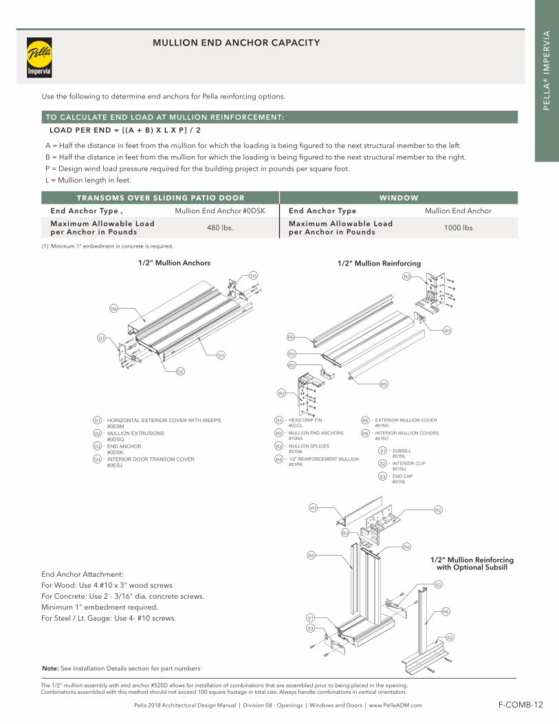
MULLION END ANCHOR CAPACITY
TRANSOMS OVER SLIDING PATIO DOOR WINDOW
End Anchor Type 1 Mullion End Anchor #0DSK End Anchor Type Mullion End Anchor
Maximum Allowable Load per Anchor in Pounds 480 lbs. Maximum Allowable Load
per Anchor in Pounds 1000 lbs
TO CALCULATE END LOAD AT MULLION REINFORCEMENT:
LOAD PER END = [(A + B) X L X P] / 2
A = Half the distance in feet from the mullion for which the loading is being figured to the next structural member to the left.
B = Half the distance in feet from the mullion for which the loading is being figured to the next structural member to the right.
P = Design wind load pressure required for the building project in pounds per square foot.
L = Mullion length in feet.
Use the following to determine end anchors for Pella reinforcing options.
1/2" Mullion Anchors
The 1/2" mullion assembly with end anchor #520D allows for installation of combinations that are assembled prior to being placed in the opening. Combinations assembled with this method should not exceed 100 square footage in total size. Always handle combinations in vertical orientation.
1/2" Mullion Reinforcing
Note: See Installation Details section for part numbers
(1) Minimum 1" embedment in concrete is required.
S3
R4
R6
R3
R3
R5
R2
R2
S3
S2
S1
R5
R6
R4
R3
R2
R1#01N5EXTERIOR MULLION COVER
#0CCLHEAD DRIP FIN
#01NJINTERIOR CLIP
#01N7INTERIOR MULLION COVERS
#01PK1/2" REINFORCEMENT MULLION
#01N8MULLION SPLICES
#01NLSUBSILL
#01NLEND CAP
#10NAMULLION END ANCHORS
S1
R5
R3
S2
R6
S3
R4
R2R1
D4
D3
D2
D1#0ESMHORIZONTAL EXTERIOR COVER WITH WEEPS
#0ESJINTERIOR DOOR TRANSOM COVER
#0DSQMULLION EXTRUSIONS
#0DSKEND ANCHOR
D2
D3
D1
D3
D4
1/2" Mullion Reinforcing with Optional Subsill
End Anchor Attachment:
For Wood: Use 4 #10 x 3" wood screws
For Concrete: Use 2 - 3/16" dia. concrete screws.
Minimum 1" embedment required.
For Steel / Lt. Gauge: Use 4- #10 screws.

Pella 2018 Architectural Design Manual | Division 08 – Openings | Windows and Doors | www.PellaADM.com F-COMB-13
PE
LL
A®
IM
PE
RV
IA
DOOR AND WINDOW TYPICAL COMBINATIONSSample Calculations
1. Determine the overall size of the configuration of the combination or composite.
2. Determine the required windload (design pressure).Project description: Location: Pella, IA
Based on in ASCE 7-05, Minimum Design Loads for Buildings and Other Structures
Wind speed = 90 mph, Exposure C
Design Pressure: 28 psf
INDIVIDUAL WINDOW PERFORMANCE: UNIT A INDIVIDUAL WINDOW PERFORMANCE: UNIT B
Project design pressure: 28 psf
Required window / door performance class and grade rating: R30
Applicable Product – Pella Impervia Fixed Window
Individual window size and performance:
6050 – Performance Class and Grade = C50
Therefore selected windows meet design pressure requirements.
Project design pressure: 28 psf
Required window / door performance class and grade rating: R30
Applicable Product - Pella Impervia 2-Wide Fixed Window Composite with Integral Mullion:
3020-2 - Performance Class and Grade = LC30
1 - Integral Mullion
Therefore selected windows meet design pressure requirements.
5. Determine if the combination will be factory assembled or non-factory assembled.
For this example, portions of the window assembly are factory assembled and some are non-factory assembled.
6. Determine mullion types and reinforcement requirements:
Windload (lateral loading) YES if yes, joint type: Joint 2 = two-way joint
Joint 3 = four-way joint
Dead Load (above doors and awning) Not Applicable .
Continued on next page
The following sample calculations are based on steps 1-8 on page 3.
4. Determine glazing performance:
See example in Section C– Glass Design Pressure Performance Charts. 6050 – Performance = 178 psf
3020 – Performance = 112 psf
Therefore selected window glazing meets design pressure requirements.
Product: Pel la ® Impervia ® Fixed Window
1 Intregral Mullion
2 Mullion type to be determined
3 Mullion type to be determined
3. Determine individual window / door size and performance (nominal sizing).

Pella 2018 Architectural Design Manual | Division 08 – Openings | Windows and Doors | www.PellaADM.com F-COMB-14
PE
LL
A®
IM
PE
RV
IA
DOOR AND WINDOW TYPICAL COMBINATIONSSample Calculations
Reinforcing mullion results:
Joint 2 : Minimum reinforcing mullion C = 1/2" Reinforcing Mullion. We will use D = 2- 2x4 wood studs for this example.
7. Determine the appropriate mullion reinforcing:
(SEE PAGES 3–6 IN THIS SECTION FOR NOTES AND INSTRUCTIONS)
Continued on next page
Determine reinforcing mullion for joint 2 (horizontal mullion) = Two way Joint 2
A. Determine L = Mullion length (in)
B. Determine W = Windload width (in)
a. 1/2 the distance from the mullion to the member above = 30"
b. 1/2 the distance from the mullion to the member below = 12"
72"42"
C. Determine minimum reinforcing mullion required
Step 1 Enter the graph at the point of the mullion length (L).
Step 2 Move to the loading width (W).
Step 3 Move right to the column with the design pressure.
Use 72"Use 45"
Use 30 psf
MAXIMUM ALLOWABLE DESIGN PRESSURE (PSF)
L (in) W (in) 20 25 30 35 40 45 50
72 30 A B C C C C C72 35 B C C C C C C72 40 C C C C C C C72 45 C C C C C C D72 50 C C C C C D F72 55 C C C C D F F72 60 C C C C D F F
See actual mullion load charts in this section for details.1
2
3

Pella 2018 Architectural Design Manual | Division 08 – Openings | Windows and Doors | www.PellaADM.com F-COMB-15
PE
LL
A®
IM
PE
RV
IA
DOOR AND WINDOW TYPICAL COMBINATIONSSample Calculations
FINAL LAYOUT AND DETAIL:
8. Determine actual rough opening size and window data:
MINIMUM REINFORCING MULLION: G = 2-18 ga 1-3/8" x 3-5/8" steel studs. We will use 2 - 2x6 wood stud reinforcement for this example.
Determine reinforcing mullion for joint 3 = Four-Way Joint Joint 3
A. Determine L = Mullion length (in) Rough Opening Width
B. Determine W = Windload width (in)
a. 1/2 the distance from the mullion to the left member = 36"
b. 1/2 the distance from the mullion to the right member = 36"
84"72"
C. Determine minimum reinforcing mullion required
Step 1 Enter the graph at the point of the mullion length (L).
Step 2 Move to the loading width (W).
Step 3 Move right to the column with the design pressure.
Use 96"Use 75"
Use 30 psf
See actual mullion load charts in this section for details. (—) = Not Applicable
MAXIMUM ALLOWABLE DESIGN PRESSURE (PSF)
L (in) W (in) 20 25 30 35 40 45 50
96 50 F F F F G G I96 55 F F F G G I I96 60 F F G G I I I96 65 F F G G I I I96 70 F F G I I I I96 75 F G G I I I —96 80 F G I I I — —
1
2
3
ROUGH OPENING WIDTH: EXAMPLE:
Rough Opening 144"
Jamb Clearance (1/4" x 2) - 1/2"
Number of vertical mullions x (mullion reinforcement width + clearance when required) (1x3" + (1/4"x2) -3-1/2"
Total Window width 140"
Window width ÷ number of windows 70"
ROUGH OPENING HEIGHT: EXAMPLE :
Rough Opening 84"
Sill and head clearance (1/4" x 2) - 1/2"
Number of horizontal mullions x (reinforcing mullion width + clearance when required) (1x3" + (1/4"x2) -3-1/2"
Total unit height (Use 4'8" frame height over 2'0" frame height units) 80"
1 Integral Mullion
2 2 - 2" x 4" Nominal Wood Reinforcing Mullion
3 2 - 2" x 6" Nominal Wood Reinforcing Mullion

Pella 2018 Architectural Design Manual | Division 08 – Openings | Windows and Doors | www.PellaADM.com F-COMB-16
PE
LL
A®
IM
PE
RV
IA
TWO-WAY AWNING AND CASEMENT JOINT LOAD TABLEWindow Mulled to Window3-1/4" Block Frame
MAXIMUM ALLOWABLE DESIGN PRESSURE (PSF)
L (in) W (in) 20 25 30 35 40 45 5042 66 A A A A A A A42 72 A A A A A A B48 36 A A A A A A A48 48 A A A A A A B48 54 A A A A A B B48 60 A A A A B B B48 66 A A A A B B B48 72 A A A B B B B54 30 A A A A A A A54 36 A A A A A A B54 48 A A A B B B B54 54 A A A B B B B54 60 A A B B B B B54 66 A B B B B B C54 72 A B B B B C C60 18 A A A A A A A60 24 A A A A A A B60 28 A A A A A B B60 30 A A A A B B B60 36 A A A B B B B60 48 A B B B B B C60 54 A B B B B C C60 60 B B B B C C D60 66 B B B B C D D60 72 B B B C D D D72 18 A A A A B B B72 24 A A B B B B B72 28 A B B B B B C72 30 A B B B B C C72 36 B B B B C D D72 48 B B C D D D D72 54 B C D D D D E72 60 B C D D D E E72 66 B D D D E E F72 72 C D D E E F G78 18 A A B B B B B78 24 A B B B B C C78 28 B B B B C D D78 30 B B B B C D D78 36 B B C D D D D78 48 B C D D D E E78 54 C D D D E E F78 60 C D D E E F G78 66 D D E E F G G78 72 D D E F G G H80 18 A A B B B B B80 24 A B B B B C D80 28 B B B B C D D80 30 B B B C D D D80 36 B B C D D D D80 48 B D D D E E F80 54 C D D E E F G80 60 D D D E F G G80 66 D D E F G G H80 72 D D E F G H H86 18 A B B B B C C86 24 B B B C D D D86 28 B B C D D D D86 30 B B C D D D E86 36 B C D D D E E86 48 D D D E F G G86 54 D D E F G G H86 60 D E E G G H H86 66 D E F G H H H86 72 D E G H H H H
1" x 3" Tube Mullion
MullionCombination (Joining)A
Kw/ Steel1" x 4 1/4" Tube Mullion
I 1" x 4 1/4" Tube Mullion
G
with Steel1/2" Reinforcing Mullion
J
Nominal Wood2 x 6
Nominal Wood2 x 4
H
E
Nominal Wood(2)-2 x 4
Steel Stud20 ga 1-3/8" x 6"
C
D
L
Nominal Wood(2)-2 x 6
Steel Stud18 ga 1-3/8" x 3-5/8"
F
BReinforcement Mullion1/2" Aluminum
• All reinforcing mullions must be properly secured at ends. Wall framing around window opening must be adequate to withstand wind loads transferred from window composite and reinforcing mullions.
• Do not use these accessories or mullions for structural vertical loading. Reinforcing mullions are for wind loading only.
• If mullion length or load factor exceed chart values, please contact your local Pella sales representative.
• Design charts are not valid for locations where impact forces from airborne debris must be considered.
• To determine allowable mullion wind load for L / 175 ≤ .75" deflection go to page 3 for instructions.
Continued on next page
(1) Factory Assembled Combination

Pella 2018 Architectural Design Manual | Division 08 – Openings | Windows and Doors | www.PellaADM.com F-COMB-17
PE
LL
A®
IM
PE
RV
IA
TWO-WAY AWNING AND CASEMENT JOINT LOAD TABLEWindow Mulled to Window3-1/4" Block Frame
1" x 3" Tube Mullion
MullionCombination (Joining)A
Kw/ Steel1" x 4 1/4" Tube Mullion
I 1" x 4 1/4" Tube Mullion
G
with Steel1/2" Reinforcing Mullion
J
Nominal Wood2 x 6
Nominal Wood2 x 4
H
E
Nominal Wood(2)-2 x 4
Steel Stud20 ga 1-3/8" x 6"
C
D
L
Nominal Wood(2)-2 x 6
Steel Stud18 ga 1-3/8" x 3-5/8"
F
BReinforcement Mullion1/2" Aluminum
• All reinforcing mullions must be properly secured at ends. Wall framing around window opening must be adequate to withstand wind loads transferred from window composite and reinforcing mullions.
• Do not use these accessories or mullions for structural vertical loading. Reinforcing mullions are for wind loading only.
• If mullion length or load factor exceed chart values, please contact your local Pella sales representative.
• Design charts are not valid for locations where impact forces from airborne debris must be considered.
• To determine allowable mullion wind load for L / 175 ≤ .75" deflection go to page 3 for instructions.
MAXIMUM ALLOWABLE DESIGN PRESSURE (PSF)
L (in) W (in) 20 25 30 35 40 45 5090 18 B B B B C C D90 24 B B C D D D D90 28 B C D D D D E90 30 B C D D D E E90 36 C D D D E F G90 48 D D E F G H H90 54 D E F G H H H90 60 D E G G H H H90 66 E F G H H H I90 72 E G H H H H I96 18 B B B C D D D96 24 B C D D D E E96 28 B D D D E E F96 30 C D D D E F G96 36 D D E E F G H96 48 D E F G H H H96 54 E F G H H H I96 60 E G H H H I J96 66 E G H H H I K96 72 F H H H I J K
100 18 B B C D D D D100 24 B D D D E E F100 28 C D D E E F G100 30 D D D E F G G100 36 D D E F G H H100 48 E F G H H H I100 54 E G H H H I J100 60 F G H H I J K100 66 G H H H J K L100 72 G H H I J L L108 18 B C D D D E E108 24 D D D E F G G108 28 D D E F G H H108 30 D E E G G H H108 36 D E G H H H H108 48 F G H H I J K108 54 G H H H J K L108 60 G H H J K L L108 66 H H I K L L L108 72 H H J K L L L
(1) Factory Assembled Combination

Pella 2018 Architectural Design Manual | Division 08 – Openings | Windows and Doors | www.PellaADM.com F-COMB-18
PE
LL
A®
IM
PE
RV
IA
MAXIMUM ALLOWABLE DESIGN PRESSURE (PSF)
L (in) W (in) 20 25 30 35 40 45 5042 66 B* B* B* B* B* B* B*42 72 B* B* B* B* B* B* B48 36 B* B* B* B* B* B* B*48 48 B* B* B* B* B* B* B48 54 B* B* B* B* B* B B48 60 B* B* B* B* B B B48 66 B* B* B* B B B B48 72 B* B* B* B B B C54 30 B* B* B* B* B* B* B*54 36 B* B* B* B* B* B B54 48 B* B* B* B B B C54 54 B* B* B B B C C54 60 B* B* B B C C D54 66 B* B B B C D D54 72 B* B B C C D D60 18 B* B* B* B* B* B* B*60 24 B* B* B* B* B* B* B60 28 B* B* B* B* B* B B60 30 B* B* B* B* B B B60 36 B* B* B* B B B C60 48 B* B B B C D D60 54 B* B B C D D D60 60 B B C C D D D60 66 B B C D D D D60 72 B C D D D D D72 18 B* B* B* B* B B B72 24 B* B* B B B C C72 28 B* B B B C D D72 30 B* B B C C D D72 36 B B C D D D D72 48 B C D D D E E72 54 C D D D E E E72 60 C D D D E E F72 66 D D D E E F G72 72 D D E E F G G78 18 B* B* B B B C C78 24 B* B B C C D D78 28 B B C C D D D78 30 B B C D D D D78 36 B C D D D D E78 48 C D D D E E F78 54 D D D E E F G78 60 D D E E F G G78 66 D D E F G G H78 72 D E E G G H H80 18 B* B* B B B C C80 24 B* B B C D D D80 28 B B C D D D D80 30 B C C D D D D80 36 B C D D D E E80 48 D D D E E F G80 54 D D E E F G G80 60 D D E F G G H80 66 D E E G G H H80 72 D E F G H H H
• All reinforcing mullions must be properly secured at ends. Wall framing around window opening must be adequate to withstand wind loads transferred from window composite and reinforcing mullions.
• Do not use these accessories or mullions for structural vertical loading. Reinforcing mullions are for wind loading only.
• If mullion length or load factor exceed chart values, please contact your local Pella sales representative.
• Design charts are not valid for locations where impact forces from airborne debris must be considered.
• To determine allowable mullion wind load for L / 175 ≤ .75" deflection go to page 3 for instructions.
THREE-WAY AWNING AND CASEMENT JOINT LOAD TABLEWindow Mulled to Window3-1/4" Block Frame
Continued on next page
1" x 3" Tube Mullion
MullionCombination (Joining)A
Kw/ Steel1" x 4 1/4" Tube Mullion
I 1" x 4 1/4" Tube Mullion
G
with Steel1/2" Reinforcing Mullion
J
Nominal Wood2 x 6
Nominal Wood2 x 4
H
E
Nominal Wood(2)-2 x 4
Steel Stud20 ga 1-3/8" x 6"
C
D
L
Nominal Wood(2)-2 x 6
Steel Stud18 ga 1-3/8" x 3-5/8"
F
BReinforcement Mullion1/2" Aluminum

Pella 2018 Architectural Design Manual | Division 08 – Openings | Windows and Doors | www.PellaADM.com F-COMB-19
PE
LL
A®
IM
PE
RV
IA
MAXIMUM ALLOWABLE DESIGN PRESSURE (PSF)
L (in) W (in) 20 25 30 35 40 45 5086 18 B* B B C C D D86 24 B C C D D D D86 28 B C D D D D E86 30 C D D D D E E86 36 C D D D E E F86 48 D D E F G G H86 54 D E E G G H H86 60 D E F G H H H86 66 E E G H H H H86 72 E F G H H H I90 18 B B C C D D D90 24 B C D D D D E90 28 C D D D E E E90 30 C D D D E E F90 36 D D D E E G G90 48 D E E G G H H90 54 D E G G H H H90 60 E F G H H H H90 66 E G H H H H I90 72 E G H H H I J96 18 B C D D D D D96 24 C D D D E E F96 28 D D D E E F G96 30 D D D E F G G96 36 D D E F G G H96 48 E F G H H H H96 54 E G G H H H I96 60 F G H H H I J96 66 F H H H I J K96 72 G H H H J K L
• All reinforcing mullions must be properly secured at ends. Wall framing around window opening must be adequate to withstand wind loads transferred from window composite and reinforcing mullions.
• Do not use these accessories or mullions for structural vertical loading. Reinforcing mullions are for wind loading only.
• If mullion length or load factor exceed chart values, please contact your local Pella sales representative.
• Design charts are not valid for locations where impact forces from airborne debris must be considered.
• To determine allowable mullion wind load for L / 175 ≤ .75" deflection go to page 3 for instructions.
THREE-WAY AWNING AND CASEMENT JOINT LOAD TABLEWindow Mulled to Window3-1/4" Block Frame
1" x 3" Tube Mullion
MullionCombination (Joining)A
Kw/ Steel1" x 4 1/4" Tube Mullion
I 1" x 4 1/4" Tube Mullion
G
with Steel1/2" Reinforcing Mullion
J
Nominal Wood2 x 6
Nominal Wood2 x 4
H
E
Nominal Wood(2)-2 x 4
Steel Stud20 ga 1-3/8" x 6"
C
D
L
Nominal Wood(2)-2 x 6
Steel Stud18 ga 1-3/8" x 3-5/8"
F
BReinforcement Mullion1/2" Aluminum

Pella 2018 Architectural Design Manual | Division 08 – Openings | Windows and Doors | www.PellaADM.com F-COMB-20
PE
LL
A®
IM
PE
RV
IA
TWO-WAY JOINT LOAD TABLEWindow Mulled to Window3" Block Frame and 3" to 3-1/4"
Kw/ Steel1" x 4 1/4" Tube Mullion
I 1" x 4 1/4" Tube Mullion
1" x 3" Tube Mullion
G
with Steel1/2" Reinforcing Mullion
J
MullionCombination (Joining)
Reinforcement Mullion1/2" Aluminum
Nominal Wood2 x 6
Nominal Wood2 x 4
H
E
Nominal Wood(2)-2 x 4
A
Steel Stud20 ga 1-3/8" x 6"
C
D
L
Nominal Wood(2)-2 x 6
Steel Stud18 ga 1-3/8" x 3-5/8"
F
B
MAXIMUM ALLOWABLE DESIGN PRESSURE (PSF)L (in) W (in) 20 25 30 35 40 45 50
42 60 A A A A A A A
42 66 A A A A A A B
42 72 A A A A A B B
48 36 A A A A A A A
48 48 A A A A A B B
48 54 A A A A B B B
48 60 A A A B B B B
48 66 A A A B B B B
48 72 A A B B B B B
54 28 A A A A A A A
54 30 A A A A A A B
54 36 A A A A B B B
54 48 A A B B B B B
54 54 A A B B B B B
54 60 A B B B B B C
54 66 A B B B B B C
54 72 B B B B B C D
60 18 A A A A A A A
60 24 A A A A A B B
60 28 A A A A B B B
60 30 A A A B B B B
60 36 A A B B B B B
60 48 A B B B B B C
60 54 B B B B B C D
60 60 B B B B C D D
60 66 B B B C D D D
60 72 B B B C D D D
72 18 A A A B B B B
72 24 A A B B B B B
72 28 A B B B B B C
72 30 A B B B B C C
72 36 B B B B C D D
72 48 B B C D D D D
72 54 B C D D D E E
72 60 B C D D D E E
72 66 C D D D E E F
72 72 C D D E E F G
78 18 A A B B B B B
78 24 B B B B B C D
78 28 B B B B C D D
78 30 B B B C D D D
78 36 B B C D D D D
78 48 B D D D E E E
78 54 C D D D E F G
78 60 D D D E E G G
78 66 D D E E F G H
78 72 D D E F G G H
80 18 A B B B B B B
80 24 B B B B C C D
80 28 B B B C D D D
80 30 B B B C D D D
80 36 B B C D D D E
80 48 C D D D E E F
80 54 C D D E E F G
80 60 D D E E F G G
80 66 D D E F G G H
80 72 D E E G G H H
• All reinforcing mullions must be properly secured at ends. Wall framing around window opening must be adequate to withstand wind loads transferred from window composite and reinforcing mullions.
• Do not use these accessories or mullions for structural vertical loading. Reinforcing mullions are for wind loading only.
• If mullion length or load factor exceed chart values, please contact your local Pella sales representative.
• Design charts are not valid for locations where impact forces from airborne debris must be considered.
• To determine allowable mullion wind load for L / 175 ≤ .75" deflection go to page 3 for instructions.
Continued on next page

Pella 2018 Architectural Design Manual | Division 08 – Openings | Windows and Doors | www.PellaADM.com F-COMB-21
PE
LL
A®
IM
PE
RV
IA
Kw/ Steel1" x 4 1/4" Tube Mullion
I 1" x 4 1/4" Tube Mullion
1" x 3" Tube Mullion
G
with Steel1/2" Reinforcing Mullion
J
MullionCombination (Joining)
Reinforcement Mullion1/2" Aluminum
Nominal Wood2 x 6
Nominal Wood2 x 4
H
E
Nominal Wood(2)-2 x 4
A
Steel Stud20 ga 1-3/8" x 6"
C
D
L
Nominal Wood(2)-2 x 6
Steel Stud18 ga 1-3/8" x 3-5/8"
F
B
MAXIMUM ALLOWABLE DESIGN PRESSURE (PSF)L (in) W (in) 20 25 30 35 40 45 50
86 18 B B B B B C D
86 24 B B B C D D D
86 28 B B C D D D D
86 30 B C D D D D E
86 36 B D D D E E E
86 48 D D E E F G G
86 54 D D E F G H H
86 60 D E E G G H H
86 66 D E F G H H H
86 72 E E G H H H H
90 18 B B B B C D D
90 24 B B C D D D D
90 28 B C D D D E E
90 30 B C D D D E E
90 36 C D D E E F G
90 48 D D E F G H H
90 54 D E F G H H H
90 60 D E G G H H H
90 66 E F G H H H I
90 72 E G H H H I J
96 18 B B C C D D D
96 24 B C D D D E E
96 28 C D D D E E F
96 30 C D D E E F G
96 36 D D E E G G H
96 48 D E G G H H H
96 54 E F G H H H I
96 60 E G H H H I J
96 66 F G H H H J K
96 72 G H H H I K L
100 18 B B C D D D D
100 24 C D D D E E F
100 28 C D D E E F G
100 30 D D D E F G G
100 36 D D E F G H H
100 48 E F G H H H I
100 54 E G H H H I J
100 60 F G H H I J K
100 66 G H H H J K L
100 72 G H H I K L L
108 18 B D D D E E E
108 24 D D E E F G G
108 28 D D E F G H H
108 30 D E E G G H H
108 36 E E G H H H H
108 48 F G H H I J K
108 54 G H H I J K L
108 60 G H H J K L L
108 66 H H I K L L L
108 72 H H J L L L L
TWO-WAY JOINT LOAD TABLEWindow Mulled to Window3" Block Frame and 3" to 3-1/4"
• All reinforcing mullions must be properly secured at ends. Wall framing around window opening must be adequate to withstand wind loads transferred from window composite and reinforcing mullions.
• Do not use these accessories or mullions for structural vertical loading. Reinforcing mullions are for wind loading only.
• If mullion length or load factor exceed chart values, please contact your local Pella sales representative.
• Design charts are not valid for locations where impact forces from airborne debris must be considered.
• To determine allowable mullion wind load for L / 175 ≤ .75" deflection go to page 3 for instructions.

Pella 2018 Architectural Design Manual | Division 08 – Openings | Windows and Doors | www.PellaADM.com F-COMB-22
PE
LL
A®
IM
PE
RV
IA
TWO-WAY JOINT LOAD TABLEWindow Mulled to Special Shape 13" Block Frame and 3" to 3-1/4"
Kw/ Steel1" x 4 1/4" Tube Mullion
I 1" x 4 1/4" Tube Mullion
1" x 3" Tube Mullion
G
with Steel1/2" Reinforcing Mullion
J
MullionCombination (Joining)
Reinforcement Mullion1/2" Aluminum
Nominal Wood2 x 6
Nominal Wood2 x 4
H
E
Nominal Wood(2)-2 x 4
A
Steel Stud20 ga 1-3/8" x 6"
C
D
L
Nominal Wood(2)-2 x 6
Steel Stud18 ga 1-3/8" x 3-5/8"
F
B
MAXIMUM ALLOWABLE DESIGN PRESSURE (PSF)L (in) W (in) 20 25 30 35 40 45 50
42 24 A A A A A A A42 36 A A A A A A B42 48 A A A B B B B42 54 A A A B B B B42 60 A A B B B B B42 66 A A B B B B B42 72 A B B B B B B48 18 A A A A A A A48 24 A A A A A A B48 28 A A A A B B B48 30 A A A A B B B48 36 A A A B B B B48 48 A B B B B B B48 54 A B B B B B B48 60 B B B B B B B48 66 B B B B B B B48 72 B B B B B B C54 18 A A A A A B B54 24 A A A B B B B54 28 A A B B B B B54 30 A A B B B B B54 36 A B B B B B B54 48 B B B B B B C54 54 B B B B B C C54 60 B B B B C C D54 66 B B B B C D D54 72 B B B C C D D60 18 A A A B B B B60 24 A B B B B B B60 28 A B B B B B B60 30 B B B B B B B60 36 B B B B B B C60 48 B B B B C D D60 54 B B B C D D D60 60 B B C C D D D60 66 B B C D D D D60 72 B C D D D D D72 18 B B B B B B B72 24 B B B B B C C72 28 B B B B C D D72 30 B B B C C D D72 36 B B C D D D D72 48 B C D D D E E72 54 C D D D E E E72 60 C D D D E E F72 66 D D D E E F G72 72 D D E E F G G78 18 B B B B B C C78 24 B B B C C D D78 28 B B C D D D D78 30 B B C D D D D78 36 B C D D D D E78 48 C D D D E E F78 54 D D D E E F G78 60 D D E E F G G78 66 D D E F G G H78 72 D E E G G H H
MAXIMUM ALLOWABLE DESIGN PRESSURE (PSF)L (in) W (in) 20 25 30 35 40 45 50
80 18 B B B B B C C80 24 B B B C D D D80 28 B B C D D D D80 30 B C C D D D D80 36 B C D D D E E80 48 D D D E E F G80 54 D D E E F G G80 60 D D E F G G H80 66 D E E G G H H80 72 D E F G H H H86 18 B B B C C D D86 24 B C C D D D D86 28 B C D D D E E86 30 C D D D D E E86 36 C D D E E E F86 48 D D E F G G H86 54 D E E G G H H86 60 D E F G H H H86 66 E F G H H H H86 72 E F G H H H I
(1) Non-Duracast® special shapes made of fiberglass-resin are available to compliment your Pella® Impervia® products.
• All reinforcing mullions must be properly secured at ends. Wall framing around window opening must be adequate to withstand wind loads transferred from window composite and reinforcing mullions.
• Do not use these accessories or mullions for structural vertical loading. Reinforcing mullions are for wind loading only.
• If mullion length or load factor exceed chart values, please contact your local Pella sales representative.
• Design charts are not valid for locations where impact forces from airborne debris must be considered.
• To determine allowable mullion wind load for L / 175 ≤ .75" deflection go to page 3 for instructions.
Continued on next page

Pella 2018 Architectural Design Manual | Division 08 – Openings | Windows and Doors | www.PellaADM.com F-COMB-23
PE
LL
A®
IM
PE
RV
IA
Kw/ Steel1" x 4 1/4" Tube Mullion
I 1" x 4 1/4" Tube Mullion
1" x 3" Tube Mullion
G
with Steel1/2" Reinforcing Mullion
J
MullionCombination (Joining)
Reinforcement Mullion1/2" Aluminum
Nominal Wood2 x 6
Nominal Wood2 x 4
H
E
Nominal Wood(2)-2 x 4
A
Steel Stud20 ga 1-3/8" x 6"
C
D
L
Nominal Wood(2)-2 x 6
Steel Stud18 ga 1-3/8" x 3-5/8"
F
B
TWO-WAY JOINT LOAD TABLEWindow Mulled to Special Shape 13" Block Frame and 3" to 3-1/4"
(1) Non-Duracast® special shapes made of fiberglass-resin are available to compliment your Pella® Impervia® products.
• All reinforcing mullions must be properly secured at ends. Wall framing around window opening must be adequate to withstand wind loads transferred from window composite and reinforcing mullions.
• Do not use these accessories or mullions for structural vertical loading. Reinforcing mullions are for wind loading only.
• If mullion length or load factor exceed chart values, please contact your local Pella sales representative.
• Design charts are not valid for locations where impact forces from airborne debris must be considered.
• To determine allowable mullion wind load for L / 175 ≤ .75" deflection go to page 3 for instructions.
MAXIMUM ALLOWABLE DESIGN PRESSURE (PSF)L (in) W (in) 20 25 30 35 40 45 50
90 18 B B C C D D D90 24 B C D D D D E90 28 C D D D E E E90 30 C D D D E E F90 36 D D D E F G G90 48 D E F G G H H90 54 D E G G H H H90 60 E F G H H H H90 66 E G H H H H I90 72 F G H H H I J96 18 B C D D D D D96 24 C D D D E E F96 28 D D D E E F G96 30 D D D E F G G96 36 D D E F G G H96 48 E F G H H H H96 54 E G G H H H I96 60 F G H H H I J96 66 G H H H I J K96 72 G H H H J K L
100 18 B C D D D E E100 24 D D D E E F G100 28 D D E E F G G100 30 D D E F G G H100 36 D E F G H H H100 48 E G H H H H I100 54 F G H H H I J100 60 G H H H I J K100 66 G H H I J K L100 72 H H H J K L L108 18 C D D D E E F108 24 D D E F G G H108 28 D E F G G H H108 30 D E F G H H H108 36 E F G H H H I108 48 G H H H I J K108 54 G H H I J L L108 60 H H I J K L L108 66 H H I K L L L108 72 H I J L L L L

Pella 2018 Architectural Design Manual | Division 08 – Openings | Windows and Doors | www.PellaADM.com F-COMB-24
PE
LL
A®
IM
PE
RV
IA
THREE-WAY JOINT LOAD TABLEWindow Mulled to Window3" Block Frame and 3" to 3-1/4"
MullionCombination (Joining)A
Kw/ Steel1" x 4 1/4" Tube Mullion
I 1" x 4 1/4" Tube Mullion
1" x 3" Tube Mullion
G
with Steel1/2" Reinforcing Mullion
J
Reinforcement Mullion1/2" Aluminum
Nominal Wood2 x 6
Nominal Wood2 x 4
H
E
Nominal Wood(2)-2 x 4
Steel Stud20 ga 1-3/8" x 6"
C
D
L
Nominal Wood(2) - 2 x 6
Steel Stud18 ga 1-3/8" x 3-5/8"
F
B
MAXIMUM ALLOWABLE DESIGN PRESSURE (PSF)L (in) W (in) 20 25 30 35 40 45 50
42 24 A A A A A A A42 36 A A A A A B B42 48 A A A B B B B42 54 A A B B B B B42 60 A A B B B B B42 66 A B B B B B B42 72 A B B B B B B48 18 A A A A A A A48 24 A A A A A B B48 28 A A A A B B B48 30 A A A B B B B48 36 A A B B B B B48 48 A B B B B B B48 54 B B B B B B B48 60 B B B B B B B48 66 B B B B B B C48 72 B B B B B B C54 18 A A A A B B B54 24 A A B B B B B54 28 A A B B B B B54 30 A B B B B B B54 36 B B B B B B B54 48 B B B B B B C54 54 B B B B B C C54 60 B B B B C C D54 66 B B B C C D D54 72 B B B C D D D60 18 A A B B B B B60 24 A B B B B B B60 28 B B B B B B B60 30 B B B B B B B60 36 B B B B B B C60 48 B B B C C D D60 54 B B B C D D D60 60 B B C D D D D60 66 B B C D D D D60 72 B C D D D D D72 18 B B B B B B B72 24 B B B B B C C72 28 B B B C C D D72 30 B B B C C D D72 36 B B C D D D D72 48 B C D D D E E72 54 C D D D E E E72 60 C D D D E E F72 66 D D D E E F G72 72 D D E E F G G78 18 B B B B B C C78 24 B B B C D D D78 28 B B C D D D D78 30 B B C D D D D78 36 B C D D D D E78 48 D D D E E E F78 54 D D D E E G G78 60 D D E E F G G78 66 D D E F G G H78 72 D E E G G H H80 18 B B B B C C D80 24 B B C C D D D80 28 B B C D D D D80 30 B C D D D D D80 36 C D D D D E E80 48 D D D E E F G80 54 D D E E F G G80 60 D D E F G G H80 66 D E E G G H H80 72 D E F G H H H
(—) = Not Applicable
• All reinforcing mullions must be properly secured at ends. Wall framing around window opening must be adequate to withstand wind loads transferred from window composite and reinforcing mullions.
• Do not use these accessories or mullions for structural vertical loading. Reinforcing mullions are for wind loading only.
• If mullion length or load factor exceed chart values, please contact your local Pella sales representative.
• Design charts are not valid for locations where impact forces from airborne debris must be considered.
• To determine allowable mullion wind load for L / 175 ≤ .75" deflection go to page 3 for instructions.
Continued on next page

Pella 2018 Architectural Design Manual | Division 08 – Openings | Windows and Doors | www.PellaADM.com F-COMB-25
PE
LL
A®
IM
PE
RV
IA
MullionCombination (Joining)A
Kw/ Steel1" x 4 1/4" Tube Mullion
I 1" x 4 1/4" Tube Mullion
1" x 3" Tube Mullion
G
with Steel1/2" Reinforcing Mullion
J
Reinforcement Mullion1/2" Aluminum
Nominal Wood2 x 6
Nominal Wood2 x 4
H
E
Nominal Wood(2)-2 x 4
Steel Stud20 ga 1-3/8" x 6"
C
D
L
Nominal Wood(2) - 2 x 6
Steel Stud18 ga 1-3/8" x 3-5/8"
F
B
(—) = Not Applicable
• All reinforcing mullions must be properly secured at ends. Wall framing around window opening must be adequate to withstand wind loads transferred from window composite and reinforcing mullions.
• Do not use these accessories or mullions for structural vertical loading. Reinforcing mullions are for wind loading only.
• If mullion length or load factor exceed chart values, please contact your local Pella sales representative.
• Design charts are not valid for locations where impact forces from airborne debris must be considered.
• To determine allowable mullion wind load for L / 175 ≤ .75" deflection go to page 3 for instructions.
MAXIMUM ALLOWABLE DESIGN PRESSURE (PSF)L (in) W (in) 20 25 30 35 40 45 50
86 18 B B B C D D D86 24 B C D D D D D86 28 B C D D D E E86 30 C D D D D E E86 36 D D D E E E F86 48 D D E F G G H86 54 D E E G G H H86 60 D E F G H H H86 66 E F G H H H H86 72 E F G H H H I90 18 B B C D D D D90 24 B C D D D D E90 28 C D D D E E E90 30 C D D D E E F90 36 D D D E F G G90 48 D E F G G H H90 54 D E G G H H H90 60 E F G H H H H90 66 E G H H H H I90 72 F G H H H I J96 18 B C D D D D E96 24 C D D D E E F96 28 D D D E E F G96 30 D D E E F G G96 36 D E E F G H H96 48 E F G H H H H96 54 E G H H H H I96 60 F G H H H I J96 66 G H H H I J K96 72 G H H H J K L
100 18 C C D D D E E100 24 D D D E E F G100 28 D D E E F G G100 30 D D E F G G H100 36 D E F G H H H100 48 E G H H H H I100 54 F G H H H I J100 60 G H H H I J K100 66 G H H I J K L100 72 H H H J K L L108 18 D D D E E E F108 24 D D E F G G H108 28 D E F G G H H108 30 D E F G H H H108 36 E F G H H H I108 48 G H H H I J K108 54 G H H I J L L108 60 H H I J K L L108 66 H H J K L L L108 72 H I J L L L L
THREE-WAY JOINT LOAD TABLEWindow Mulled to Window3" Block Frame and 3" to 3-1/4"

Pella 2018 Architectural Design Manual | Division 08 – Openings | Windows and Doors | www.PellaADM.com F-COMB-26
PE
LL
A®
IM
PE
RV
IA
THREE-WAY JOINT LOAD TABLEWindow Mulled to Special Shape 13" Block Frame
(—) = Not Applicable
(1) Non-Duracast® special shapes made of fiberglass-resin are available to compliment your Pella® Impervia® products.
• All reinforcing mullions must be properly secured at ends. Wall framing around window opening must be adequate to withstand wind loads transferred from window composite and reinforcing mullions.
• Do not use these accessories or mullions for structural vertical loading. Reinforcing mullions are for wind loading only.
• If mullion length or load factor exceed chart values, please contact your local Pella sales representative.
• Design charts are not valid for locations where impact forces from airborne debris must be considered.
• To determine allowable mullion wind load for L / 175 ≤ .75" deflection go to page 3 for instructions.
MAXIMUM ALLOWABLE DESIGN PRESSURE (PSF)L (in) W (in) 20 25 30 35 40 45 50
42 24 A A A A A A A42 36 A A A A A B B42 48 A A A B B B B42 54 A A B B B B B42 60 A A B B B B B42 66 A B B B B B B42 72 A B B B B B B48 18 A A A A A A A48 24 A A A A A B B48 28 A A A A B B B48 30 A A A B B B B48 36 A A B B B B B48 48 A B B B B B B48 54 B B B B B B B48 60 B B B B B B B48 66 B B B B B B C48 72 B B B B B B C54 18 A A A A B B B54 24 A A B B B B B54 28 A A B B B B B54 30 A B B B B B B54 36 B B B B B B B54 48 B B B B B B C54 54 B B B B B C C54 60 B B B B C C D54 66 B B B C C D D54 72 B B B C D D D60 18 A A B B B B B60 24 A B B B B B B60 28 B B B B B B B60 30 B B B B B B B60 36 B B B B B B C60 48 B B B C C D D60 54 B B B C D D D60 60 B B C D D D D60 66 B B C D D D D60 72 B C D D D D D72 18 B B B B B B B72 24 B B B B B C C72 28 B B B C C D D72 30 B B B C C D D72 36 B B C D D D D72 48 B C D D D E E72 54 C D D D E E E72 60 C D D D E E F72 66 D D D E E F G72 72 D D E E F G G78 18 B B B B B C C78 24 B B B C D D D78 28 B B C D D D D78 30 B B C D D D D78 36 B C D D D D E78 48 D D D E E E F78 54 D D D E E G G78 60 D D E E F G G78 66 D D E F G G H78 72 D E E G G H H80 18 B B B B C C D80 24 B B C C D D D80 28 B B C D D D D80 30 B C D D D D D80 36 C D D D D E E80 48 D D D E E F G80 54 D D E E F G G80 60 D D E F G G H80 66 D E E G G H H80 72 D E F G H H H
Continued on next page
Kw/ Steel1" x 4 1/4" Tube Mullion
I 1" x 4 1/4" Tube Mullion
1" x 3" Tube Mullion
G
with Steel1/2" Reinforcing Mullion
J
MullionCombination (Joining)
Reinforcement Mullion1/2" Aluminum
Nominal Wood2 x 6
Nominal Wood2 x 4
H
E
Nominal Wood(2)-2 x 4
A
Steel Stud20 ga 1-3/8" x 6"
C
D
L
Nominal Wood(2)-2 x 6
Steel Stud18 ga 1-3/8" x 3-5/8"
F
B

Pella 2018 Architectural Design Manual | Division 08 – Openings | Windows and Doors | www.PellaADM.com F-COMB-27
PE
LL
A®
IM
PE
RV
IA
(—) = Not Applicable
(1) Non-Duracast® special shapes made of fiberglass-resin are available to compliment your Pella® Impervia® products.
• All reinforcing mullions must be properly secured at ends. Wall framing around window opening must be adequate to withstand wind loads transferred from window composite and reinforcing mullions.
• Do not use these accessories or mullions for structural vertical loading. Reinforcing mullions are for wind loading only.
• If mullion length or load factor exceed chart values, please contact your local Pella sales representative.
• Design charts are not valid for locations where impact forces from airborne debris must be considered.
• To determine allowable mullion wind load for L / 175 ≤ .75" deflection go to page 3 for instructions.
Kw/ Steel1" x 4 1/4" Tube Mullion
I 1" x 4 1/4" Tube Mullion
1" x 3" Tube Mullion
G
with Steel1/2" Reinforcing Mullion
J
MullionCombination (Joining)
Reinforcement Mullion1/2" Aluminum
Nominal Wood2 x 6
Nominal Wood2 x 4
H
E
Nominal Wood(2)-2 x 4
A
Steel Stud20 ga 1-3/8" x 6"
C
D
L
Nominal Wood(2)-2 x 6
Steel Stud18 ga 1-3/8" x 3-5/8"
F
B
MAXIMUM ALLOWABLE DESIGN PRESSURE (PSF)L (in) W (in) 20 25 30 35 40 45 50
86 18 B B B C D D D86 24 B C D D D D D86 28 B C D D D E E86 30 C D D D D E E86 36 D D D E E E F86 48 D D E F G G H86 54 D E E G G H H86 60 D E F G H H H86 66 E F G H H H H86 72 E F G H H H I90 18 B B C D D D D90 24 B C D D D D E90 28 C D D D E E E90 30 C D D D E E F90 36 D D D E F G G90 48 D E F G G H H90 54 D E G G H H H90 60 E F G H H H H90 66 E G H H H H I90 72 F G H H H I J96 18 B C D D D D E96 24 C D D D E E F96 28 D D D E E F G96 30 D D E E F G G96 36 D E E F G H H96 48 E F G H H H H96 54 E G H H H H I96 60 F G H H H I J96 66 G H H H I J K96 72 G H H H J K L
100 18 C C D D D E E100 24 D D D E E F G100 28 D D E E F G G100 30 D D E F G G H100 36 D E F G H H H100 48 E G H H H H I100 54 F G H H H I J100 60 G H H H I J K100 66 G H H I J K L100 72 H H H J K L L108 18 D D D E E E F108 24 D D E F G G H108 28 D E F G G H H108 30 D E F G H H H108 36 E F G H H H I108 48 G H H H I J K108 54 G H H I J L L108 60 H H I J K L L108 66 H H J K L L L108 72 H I J L L L L
THREE-WAY JOINT LOAD TABLEWindow Mulled to Special Shape 13" Block Frame
Pella 2018 Architectural Design Manual | Division 08 – Openings | Windows and Doors | www.PellaADM.com F-COMB-28
PE
LL
A®
IM
PE
RV
IA
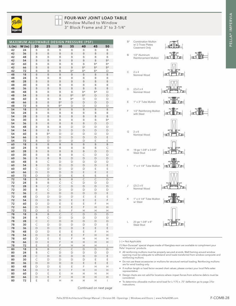
FOUR-WAY JOINT LOAD TABLEWindow Mulled to Window3" Block Frame and 3" to 3-1/4"
MAXIMUM ALLOWABLE DESIGN PRESSURE (PSF)L (in) W (in) 20 25 30 35 40 45 50
42 24 B B B B B B B42 36 B B B B B B B42 48 B B B B B B B42 54 B B B B B B B*42 60 B B B B B B* B*42 66 B B B B B* B* B*42 72 B B B B* B* B* D48 18 B B B B B B B48 24 B B B B B B B48 28 B B B B B B B48 30 B B B B B B B48 36 B B B B B B B48 48 B B B B B* B* D48 54 B B B B* B* D D48 60 B B B B* D D D48 66 B B B* D D D D48 72 B B B* D D D D54 18 B B B B B B B54 24 B B B B B B B54 28 B B B B B B B54 30 B B B B B B B*54 36 B B B B B D D54 48 B B B D D D D54 54 B B D D D D D54 60 B B* D D D D D54 66 B D D D D D E54 72 B D D D D E E60 18 B B B B B B B60 24 B B B B B B C60 28 B B B B B D D60 30 B B B B C D D60 36 B B B D D D D60 48 B C D D D D D60 54 B D D D D D E60 60 C D D D D E E60 66 D D D D E E E60 72 D D D E E E E72 18 B B B B C C D72 24 B B C C D D D72 28 B C C D D D D72 30 B C D D D D D72 36 C D D D D D E72 48 D D D D E E E72 54 D D D E E E F72 60 D D E E E F H72 66 D D E E F H H72 72 D E E F H H H78 18 B B C C D D D78 24 B C D D D D D78 28 C C D D D D D78 30 C D D D D D E78 36 D D D D E E E78 48 D D E E E F H78 54 D D E E F H H78 60 D E E F H H H78 66 D E F H H H H78 72 E E F H H H I80 18 B B C C D D D80 24 B C D D D D D80 28 C D D D D D E80 30 C D D D D E E80 36 D D D D E E E80 48 D D E E F H H80 54 D E E F H H H80 60 D E E H H H H80 66 D E F H H H H80 72 E E H H H H I
Casement Onlyw/ 2-Truss PlatesCombination MullionB*
Kw/ Steel1" x 4 1/4" Tube Mullion
I 1" x 4 1/4" Tube Mullion
1" x 3" Tube Mullion
G
with Steel1/2" Reinforcing Mullion
J
Reinforcement Mullion1/2" Aluminum
Nominal Wood2 x 6
Nominal Wood2 x 4
H
E
Nominal Wood(2)-2 x 4
Steel Stud20 ga 1-3/8" x 6"
C
D
L
Nominal Wood(2)-2 x 6
Steel Stud18 ga 1-3/8" x 3-5/8"
F
B
(—) = Not Applicable
(1) Non-Duracast® special shapes made of fiberglass-resin are available to compliment your Pella® Impervia® products.
• All reinforcing mullions must be properly secured at ends. Wall framing around window opening must be adequate to withstand wind loads transferred from window composite and reinforcing mullions.
• Do not use these accessories or mullions for structural vertical loading. Reinforcing mullions are for wind loading only.
• If mullion length or load factor exceed chart values, please contact your local Pella sales representative.
• Design charts are not valid for locations where impact forces from airborne debris must be considered.
• To determine allowable mullion wind load for L / 175 ≤ .75" deflection go to page 3 for instructions.
Continued on next page

Pella 2018 Architectural Design Manual | Division 08 – Openings | Windows and Doors | www.PellaADM.com F-COMB-29
PE
LL
A®
IM
PE
RV
IA
Casement Onlyw/ 2-Truss PlatesCombination MullionB*
Kw/ Steel1" x 4 1/4" Tube Mullion
I 1" x 4 1/4" Tube Mullion
1" x 3" Tube Mullion
G
with Steel1/2" Reinforcing Mullion
J
Reinforcement Mullion1/2" Aluminum
Nominal Wood2 x 6
Nominal Wood2 x 4
H
E
Nominal Wood(2)-2 x 4
Steel Stud20 ga 1-3/8" x 6"
C
D
L
Nominal Wood(2)-2 x 6
Steel Stud18 ga 1-3/8" x 3-5/8"
F
B
(—) = Not Applicable
(1) Non-Duracast® special shapes made of fiberglass-resin are available to compliment your Pella® Impervia® products.
• All reinforcing mullions must be properly secured at ends. Wall framing around window opening must be adequate to withstand wind loads transferred from window composite and reinforcing mullions.
• Do not use these accessories or mullions for structural vertical loading. Reinforcing mullions are for wind loading only.
• If mullion length or load factor exceed chart values, please contact your local Pella sales representative.
• Design charts are not valid for locations where impact forces from airborne debris must be considered.
• To determine allowable mullion wind load for L / 175 ≤ .75" deflection go to page 3 for instructions.
MAXIMUM ALLOWABLE DESIGN PRESSURE (PSF)L (in) W (in) 20 25 30 35 40 45 50
86 18 B C D D D D D86 24 C D D D D E E86 28 D D D D E E E86 30 D D D D E E F86 36 D D E E E F H86 48 D E E H H H H86 54 E E F H H H H86 60 E F H H H H I86 66 E H H H H I I86 72 E H H H I I I90 18 C C D D D D D90 24 D D D D E E E90 28 D D D E E E F90 30 D D D E E F H90 36 D D E E H H H90 48 E E H H H H H90 54 E F H H H H I90 60 E H H H H I I90 66 F H H H I I K90 72 H H H H I I K96 18 C D D D D E E96 24 D D D E E F H96 28 D D E E F H H96 30 D D E F H H H96 36 D E F H H H H96 48 E H H H H H I96 54 F H H H H I K96 60 H H H H I K K96 66 H H H I I K K96 72 H H H I K K **
100 18 D D D D E E E100 24 D D E E F G H100 28 D E E F H H H100 30 D E E G H H H100 36 E E G H H H H100 48 F H H H H I K100 54 G H H H I K K100 60 H H H H K K L100 66 H H H I K L L100 72 H H I K K L **108 18 D D E E E F G108 24 D E E G H H H108 28 E E G H H H H108 30 E F G H H H H108 36 E G H H H H I108 48 H H H H K K L108 54 H H H K K L L108 60 H H I K L L **108 66 H H K K L ** **108 72 H I K L ** ** **114 18 D D E F G G H114 24 E E G H H H H114 28 E F H H H H H114 30 E G H H H H I114 36 G H H H I J K114 48 H H I K K L L114 54 H H J K L L **114 60 H I K L L ** **114 66 H J L L ** ** **114 72 I K L L ** ** **120 18 D E F G G H H120 24 E F G H H H H120 28 F G H H H I J120 30 F G H H H I J120 36 G H H I J K L120 48 H H J K L L **120 54 H I K L L ** **120 60 H J L L ** ** **120 66 I K L ** ** ** **120 72 J L L ** ** ** **
FOUR-WAY JOINT LOAD TABLEWindow Mulled to Window3" Block Frame and 3" to 3-1/4"

Pella 2018 Architectural Design Manual | Division 08 – Openings | Windows and Doors | www.PellaADM.com F-COMB-30
PE
LL
A®
IM
PE
RV
IA
TWO-WAY JOINT LOAD TABLEDoor Mulled to Transom (Horizontal only)
Maximum Allowable Design Pressure (psf)
L (in) W (in) 20 25 30 35 40 45 50
60 66 A A A A A A A
60 72 A A A A A A B
60 78 A A A A A B B
60 80 A A A A A B B
60 86 A A A A B B B
60 90 A A A A B B B
60 96 A A A B B B B
72 36 A A A A A A A
72 48 A A A A A B B
72 54 A A A A B B B
72 60 A A A B B B C
72 66 A A B B B C C
72 72 A A B B C C D
72 78 A B B B C D E
72 80 A B B B C D E
72 86 A B B C D E E
72 90 A B B C D E F
72 96 A B C C E E F
86 36 A A A B B B C
86 48 A B B C C D E
86 54 A B B C D E F
86 60 B B C D E F F
86 66 B B C E F F G
86 72 B C D E F G G
86 78 B C E F F G H
86 80 B D E F F G H
86 86 C D E F G H H
86 90 C E F F G H I
86 96 C E F G H H I
96 36 A B B C D E E
96 48 B C D E F F G
96 54 B C E F F G H
96 60 C D E F G H H
96 66 C E F G H H I
96 72 D E F G H I J
96 78 D F G H H J K
96 80 E F G H H J K
96 86 E F G H I K L
96 90 E F H H J K L
96 96 F G H I K L L
w/ SteelTube Mullion1" x 4 1/4"
Tube Mullion1" x 4 1/4"
Tube Mullion1" x 3"
Steel Stud1-3/8" x 3-5/8" 18 ga
H
Nominal Wood2 x 6
K
F
E
IB
Nominal Wood2 x 4
A
Mullion(Joining) Combination
C
Mullion1/2" Reinforcing
D
G
J
L
Mullion w/ steel1/2" Reinforcing
Steel Stud1-3/8" x 6" (2)-20 ga
Nominal Wood(2)-2 x 4
Nominal Wood(2)-2 x 6
• All reinforcing mullions must be properly secured at ends. Wall framing around window opening must be adequate to withstand wind loads transferred from window composite and reinforcing mullions.
• Do not use these accessories or mullions for structural vertical loading. Reinforcing mullions are for wind loading only.
• If mullion length or load factor exceed chart values, please contact your local Pella sales representative.
• Design charts are not valid for locations where impact forces from airborne debris must be considered.
• To determine allowable mullion wind load for L / 175 ≤ .75" deflection go to page 3 for instructions.

Pella 2018 Architectural Design Manual | Division 08 – Openings | Windows and Doors | www.PellaADM.com F-COMB-31
PE
LL
A®
IM
PE
RV
IA
TWO-WAY JOINT LOAD TABLEDoor Mulled to Door Vertical mullion
KTube Mullion w/ Steel1" x 4 1/4"
ITube Mullion1" x 4 1/4"
Nominal Wood2 x 6F
Nominal Wood2 x 4B
AMullionCombination (Joining)
D
H
J
LSteel Stud(2)-20 ga 1-3/8" x 6"
Nominal Wood(2)-2 x 4
Nominal Wood(2)-2 x 6
Steel Stud18 ga 1-3/8" x 3-5/8"
MAXIMUM ALLOWABLE DESIGN PRESSURE (PSF)L (in) W (in) 20 25 30 35 40 45 50
72 60 A A A A A A A72 66 A A A A A A B72 72 A A A A A A B72 78 A A A A A B B72 80 A A A A A B B72 86 A A A A B B D72 90 A A A A B B D72 96 A A A B B D D78 36 A A A A A A A78 48 A A A A A A A78 54 A A A A A A B78 60 A A A A A B B78 66 A A A A B B D78 72 A A A A B B D78 78 A A A B B D D78 80 A A A B B D E78 86 A A B B D D E78 90 A A B B D E E78 96 A A B D D E F80 36 A A A A A A A80 48 A A A A A A B80 54 A A A A A B B80 60 A A A A B B B80 66 A A A A B B D80 72 A A A B B D D80 78 A A A B D D E80 80 A A B B D D E80 86 A A B B D E F80 90 A A B D D E F80 96 A B B D E F F86 36 A A A A A A A86 48 A A A A B B B86 54 A A A A B B D86 60 A A A B B D E86 66 A A B B D D E86 72 A A B D D E F86 78 A B B D E F F86 80 A B B D E F H86 86 A B D E F F H86 90 A B D E F H H86 96 B B D E F H H90 36 A A A A A A B90 48 A A A B B D D90 54 A A A B D D E90 60 A A B B D E F90 66 A A B D E F F90 72 A B D D E F H90 78 A B D E F H H90 80 A B D E F H H90 86 B D D F F H H90 90 B D E F H H H90 96 B D E F H H I96 36 A A A A B B D96 48 A A B B D E E96 54 A A B D E F F96 60 A B D D E F H96 66 A B D E F H H96 72 B D E F H H H96 78 B D E F H H I96 80 B D E F H H I96 86 B E F H H I J96 90 D E F H H I K96 96 D E H H I J L
• All reinforcing mullions must be properly secured at ends. Wall framing around window opening must be adequate to withstand wind loads transferred from window composite and reinforcing mullions.
• Do not use these accessories or mullions for structural vertical loading. Reinforcing mullions are for wind loading only.
• If mullion length or load factor exceed chart values, please contact your local Pella sales representative.
• Design charts are not valid for locations where impact forces from airborne debris must be considered.
• To determine allowable mullion wind load for L / 175 ≤ .75" deflection go to page 3 for instructions.

Pella 2018 Architectural Design Manual | Division 08 – Openings | Windows and Doors | www.PellaADM.com F-COMB-32
PE
LL
A®
IM
PE
RV
IA
THREE-WAY JOINT LOAD TABLEDoor Mulled to Two Transoms
• All reinforcing mullions must be properly secured at ends. Wall framing around window opening must be adequate to withstand wind loads transferred from window composite and reinforcing mullions.
• Do not use these accessories or mullions for structural vertical loading. Reinforcing mullions are for wind loading only.
• If mullion length or load factor exceed chart values, please contact your local Pella sales representative.
• Design charts are not valid for locations where impact forces from airborne debris must be considered.
• To determine allowable mullion wind load for L / 175 ≤ .75" deflection go to page 3 for instructions.
MAXIMUM ALLOWABLE DESIGN PRESSURE (PSF)L (in) W (in) 20 25 30 35 40 45 50
60 54 A A A A A A A60 60 A A A A A A B60 66 A A A A A B B60 72 A A A A B B B60 78 A A A A B B B60 80 A A A A B B B60 86 A A A B B B B60 90 A A A B B B C60 96 A A B B B B C
72 36 A A A A A A B72 48 A A A B B B B72 54 A A A B B B C72 60 A A B B B C C72 66 A B B B C C D72 72 A B B B C D E72 78 A B B C D E E72 80 A B B C D E E72 86 B B C C D E F72 90 B B C D E E F72 96 B B C D E F F
86 36 A A B B B C C86 48 B B B C D E E86 54 B B C D E F F86 60 B C C E E F F86 66 B C D E F F G86 72 B C E F F G H86 78 C D E F G H H86 80 C D E F G H H86 86 C E F F H H H86 90 C E F G H H I86 96 D E F G H I J
96 36 B B C C D E F96 48 B C D E F F G96 54 C D E F F G H96 60 C E F F G H H96 66 D E F G H H I96 72 D F F H H I J96 78 E F G H I J K96 80 E F G H I J K96 86 E F H H J K L96 90 F G H I J L L96 96 F G H I K L L
w/ SteelTube Mullion1" x 4 1/4"
Tube Mullion1" x 4 1/4"
Tube Mullion1" x 3"
Steel Stud1-3/8" x 3-5/8" 18 ga
H
Nominal Wood2 x 6
K
F
E
IB
Nominal Wood2 x 4
A
Mullion(Joining) Combination
C
Mullion1/2" Reinforcing
D
G
J
L
Mullion w/ steel1/2" Reinforcing
Steel Stud1-3/8" x 6" (2)-20 ga
Nominal Wood(2)-2 x 4
Nominal Wood(2)-2 x 6