general purpose high temperature 302y 304y - tomoe · pdf filefcd450 (tufftride treated) or...
TRANSCRIPT
302Y-01304Y
Metal seat
Bearing
Seat retainer
Gasket packing
Set screw
Seat ring(stainless steel)
Backup spring(patent pending)
Disc(stainless steel)
Body(ductile/stainless steel)
Ball
PTFE seat
Bearing
Seat retainer
Set screw
Disc(stainless steel)
Body(ductile/stainless steel)
PTFE seat ring
Ball
Lock Lever Worm Gear PneumaticCylinder Motorized
General Purpose High Temperatureand High Pressure Service Valves
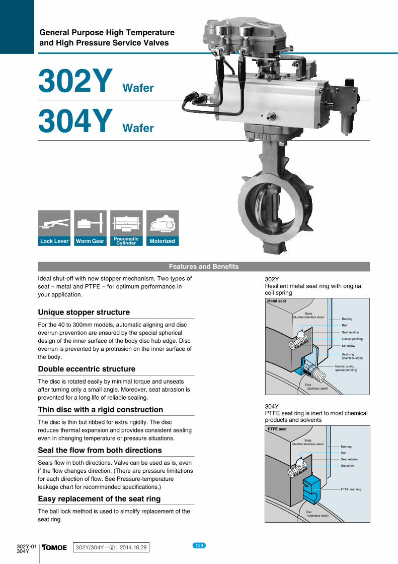
Ideal shut-off with new stopper mechanism. Two types of seat – metal and PTFE – for optimum performance in your application.
For the 40 to 300mm models, automatic aligning and disc overrun prevention are ensured by the special spherical design of the inner surface of the body disc hub edge. Disc overrun is prevented by a protrusion on the inner surface of the body.
The disc is rotated easily by minimal torque and unseats after turning only a small angle. Moreover, seat abrasion is prevented for a long life of reliable sealing.
Seals flow in both directions. Valve can be used as is, even if the flow changes direction. (There are pressure limitations for each direction of flow. See Pressure-temperature leakage chart for recommended specifications.)
The ball lock method is used to simplify replacement of the seat ring.
The disc is thin but ribbed for extra rigidity. The disc reduces thermal expansion and provides consistent sealing even in changing temperature or pressure situations.
Features and Benefits
302YResilient metal seat ring with originalcoil spring
304YPTFE seat ring is inert to most chemical products and solvents
302Y Wafer
304Y Wafer
Unique stopper structure
Double eccentric structure
Thin disc with a rigid construction
Seal the flow from both directions
Easy replacement of the seat ring
302Y/304Y-② 2014.10.29 129

302Y-01304Y
Metal seat
Bearing
Seat retainer
Gasket packing
Set screw
Seat ring(stainless steel)
Backup spring(patent pending)
Disc(stainless steel)
Body(ductile/stainless steel)
Ball
PTFE seat
Bearing
Seat retainer
Set screw
Disc(stainless steel)
Body(ductile/stainless steel)
PTFE seat ring
Ball
Lock Lever Worm Gear PneumaticCylinder Motorized
General Purpose High Temperatureand High Pressure Service Valves
Ideal shut-off with new stopper mechanism. Two types of seat – metal and PTFE – for optimum performance in your application.
For the 40 to 300mm models, automatic aligning and disc overrun prevention are ensured by the special spherical design of the inner surface of the body disc hub edge. Disc overrun is prevented by a protrusion on the inner surface of the body.
The disc is rotated easily by minimal torque and unseats after turning only a small angle. Moreover, seat abrasion is prevented for a long life of reliable sealing.
Seals flow in both directions. Valve can be used as is, even if the flow changes direction. (There are pressure limitations for each direction of flow. See Pressure-temperature leakage chart for recommended specifications.)
The ball lock method is used to simplify replacement of the seat ring.
The disc is thin but ribbed for extra rigidity. The disc reduces thermal expansion and provides consistent sealing even in changing temperature or pressure situations.
Features and Benefits
302YResilient metal seat ring with originalcoil spring
304YPTFE seat ring is inert to most chemical products and solvents
302Y Wafer
304Y Wafer
Unique stopper structure
Double eccentric structure
Thin disc with a rigid construction
Seal the flow from both directions
Easy replacement of the seat ring
302Y/304Y-② 2014.10.29 302Y-02304Y
0.5MPa
1.5MPa
2.5MPa
2.0MPa
1.0MPa
0
※ The operating range is the area within the thick lines
degree C (Temperature)
ISO 5208Leakage rate C
1×10⁻⁵ Cv
1×10⁻⁴ Cv
1×10⁻⁵ Cv
(Pre
ssur
e)
0.5MPa
1.5MPa
2.5MPa
2.0MPa
1.0MPa
0
degree C (Temperature)
(Pre
ssur
e)
ISO 5208Leakage rate A
Standard Specifications
302Y (metal seat type) 304Y (carbon-reinforced PTFE seat type)
※1. 65mm is not applicable for BS 10 Table E.※2. For size 40mm, only SCS13A is available for the body material.
Valve typeSeat typeValve nominal size
Applicable flange standard ※1
Face-to-face dimensions
Actuator mounting flange
Pressure rating
Max. working pressureBody shell testSeat leak test
Flow direction
Seat leakageWorking temperature range
Standard materials
Bonnet type
Actuators
Coating
302YMetal seat type
40mm to 300mm
2.0MPa (250, 300mm: 1.6MPa)
On the valve disc side: 2.0MPaOn the valve stem side: 1.0MPa
The max. pressure on the valve disc sidefor 250mm and 300mm valves is 1.6MPa
ISO 5208 leakage rate C-20 to 250 degrees C
SUS316
JIS 50K/10K/16K/20K, ANSI 150lb, BS10 Table E/F,BS4504, PN 6/10/16, DIN NP 6/10/16 etc
JIS B 2002 (46 series) / ISO 5752 (20 series)
ISO 5211
ANSI (B16.34, B16.42) Class 150 lb
Max. 3.0MPaMax. 2.2MPa
FCD450 (Tufftride treated) OR SCS13ASCS13A (HdCr plating)
SUS420J2 or SUS3291J1
PTFE with carbon graphiteOpen bonnet40 to 150mm40 to 300mm40 to 300mm40 to 300mm
Under 200 degrees C: Modified silicon resin coating (Munsell N7).200 degrees C and over: Heat resistant painting (silver).
No painting for stainless steel.
304YPTFE seat type
40mm to 300mm
2.0 MPa
Bi-directionalOn the valve disc side: 2.0MPa
ISO 5208 leakage rate A (tight shut-off)-20 to 200 degrees C
RPTFE (with carbon graphite) or theoptional specification PFA + PTFE (white)
Body ※2
DiscStem
Seat ring
Gland packing
Lock leverWorm gearPneumatic cylinderMotorised
The 300 series is optimal for applications that cannot be handled by valves with rubber seats because of the temperature, pressure, fluid velocity or fluid itself. Two types are available: the 302Y with a metal seat for steam line applications and the 304Y with a PTFE seat for chemical line applications.
General Description
Pressure-Temperature Leakage Chart
130
ButterflyValve
TRITEC
TT2
334A
302A/303Q
304A/304Q
302Y/304Y
304M(HLV)
507V/508V
DTM
846T/847T/847Q
841T/842T
700Z
700G/704G/705G
700GB731P/732P/732Q/752W
71LG
700E/700K/700S
704G/722F/720F
KRV
227P
907H/908H(MKT)
903C

302Y-03304Y
302Y (metal)
304Y(PTFE)
250mm, 300mm
40mm to 300mm
18
17
16
15
14
13
19
23
3
12
8
3
5
9
1
2
22
10
11
721
20
6
4
5
302Y/304Y Expanded view of components
131

302Y-03304Y
302Y (metal)
304Y(PTFE)
250mm, 300mm
40mm to 300mm
18
17
16
15
14
13
19
23
3
12
8
3
5
9
1
2
22
10
11
721
20
6
4
5
302Y/304Y Expanded view of components
302Y-04304Y
302Y/304Y Parts list
■302Y Parts list
12345
6
789
10111213141516171819
20
21
2223
★★
★
★
★
★
★
No. Description RemarksQ’ty
No. Description RemarksQ’ty
BodyDiscStemSeat ring gasketSeat ring
Back-up spring
Seat ring retainerTop shaft bearingBottom shaft bearingBottom coverBottom gasketTaper pinPacking retainerGland packingRough glandGland flangeGland boltGland nutGland coil
Ball
Set screw
Hexagon bolt, Spring washerKey
111112341111121
1 sets112212424
4 sets1
40mm to 100mm125mm to 200mm250mm, 300mm
Only 40mm to 150mm40mm to 125mm150mm to 300mm40mm to 125mm150mm to 300mm
Only 250mm, 300mm
■304Y Parts list
1235789
10111213141516171819
20
21
2223
★
★
★
★
★
BodyDiscStemSeat ringSeat ring retainerTop shaft bearingBottom shaft bearingBottom coverBottom gasketTaper pinPacking retainerGland packingGland bushGland flangeGland boltGland nutGland coil
Ball
Set screw
Hexagon bolt, Spring washerKey
11111111121
1 sets112212424
4 sets1
Only 40mm to 150mm40mm to 125mm150mm to 300mm40mm to 125mm150mm to 300mm
Only 250mm, 300mm
Remark: The ★ indicates recommended spare parts. They are supplied as “Seat ring set” with a small hexagonal spanner to remove set screws (P.21).
132
ButterflyValve
TRITEC
TT2
334A
302A/303Q
304A/304Q
302Y/304Y
304M(HLV)
507V/508V
DTM
846T/847T/847Q
841T/842T
700Z
700G/704G/705G
700GB731P/732P/732Q/752W
71LG
700E/700K/700S
704G/722F/720F
KRV
227P
907H/908H(MKT)
903C

302Y-05304Y
0.5MPa
1.5MPa
2.5MPa
2.0MPa
1.0MPa
ー20 0 50 100 120 150 200 2500
degree C (Temperature)
(Pre
ssur
e)
THTL
302Y Actuator selection chart
302Y Pressure rating
■302Y
40
1 1/2
50
2
65
2 1/2
80
3
100
4
125
5
150
6
200
8
250
10
300
12
ModelCate-gory
Remark: For the 300mm model with the accessories below (for control), type 4I-4 should be selected. ●Micom unit ●Servo unit ●Speed control unit ●Potentiometer
1T-1 1T-2 1T-3
2U-0
T85
T200S T380S T750S
T200 T380T750
T380T200
2U-1
4 I-0
SRJ-010
4 I-2 4 I-2.5 4 I-3 4 I-4 (control)
4 I-4
SRJ-020SRJ-060 LTKD-01 0.2kW/
DGH-3
2U-2 2U-3 2U-4 DGH-2 DGH-3
4 I-1
TL
TH
TL
TH
TL
TH
TL
TH
TL
TH
TL
TH
1T
2U,2S
7E,3A TGA-125
7G,7F3U,3K TG-12S
TG-14S
4J,4L
4 I
Size mminch( (
133
302Y-05304Y
0.5MPa
1.5MPa
2.5MPa
2.0MPa
1.0MPa
ー20 0 50 100 120 150 200 2500
degree C (Temperature)
(Pre
ssur
e)
THTL
302Y Actuator selection chart
302Y Pressure rating
■302Y
40
1 1/2
50
2
65
2 1/2
80
3
100
4
125
5
150
6
200
8
250
10
300
12
ModelCate-gory
Remark: For the 300mm model with the accessories below (for control), type 4I-4 should be selected. ●Micom unit ●Servo unit ●Speed control unit ●Potentiometer
1T-1 1T-2 1T-3
2U-0
T85
T200S T380S T750S
T200 T380T750
T380T200
2U-1
4 I-0
SRJ-010
4 I-2 4 I-2.5 4 I-3 4 I-4 (control)
4 I-4
SRJ-020SRJ-060 LTKD-01 0.2kW/
DGH-3
2U-2 2U-3 2U-4 DGH-2 DGH-3
4 I-1
TL
TH
TL
TH
TL
TH
TL
TH
TL
TH
TL
TH
1T
2U,2S
7E,3A TGA-125
7G,7F3U,3K TG-12S
TG-14S
4J,4L
4 I
Size mminch( (
302Y-06304Y
degree C (Temperature)
(Pre
ssur
e)
0.5MPa
1.5MPa
2.5MPa
2.0MPa
1.0MPa
ー20 0 50 100 120 150 200 2500
T20
T10
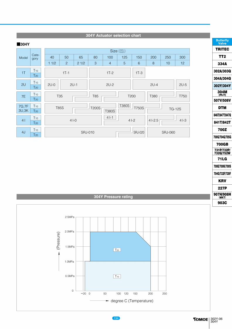
304Y Pressure rating
304Y Actuator selection chart
■304Y
40
1 1/2
50
2
65
2 1/2
80
3
100
4
125
5
150
6
200
8
250
10
300
12
ModelCate-gory
1T-1 1T-2 1T-3
2U-0 2U-1
4 I-0
SRJ-010 SRJ-020
4 I-2.5
SRJ-060
2U-2
T35
T85S
T85
T200S T750ST380S
T380S
T200 T380 T750
2U-4 2U-5
4 I-2 4 I-34 I-1
T10
T20
T10
T20
T10
T20
T10
T20
T10
T20
T10
T20
1T
2U
7E
7G,7F3U,3K TG-12S
4J
4 I
Size mminch( (
134
ButterflyValve
TRITEC
TT2
334A
302A/303Q
304A/304Q
302Y/304Y
304M(HLV)
507V/508V
DTM
846T/847T/847Q
841T/842T
700Z
700G/704G/705G
700GB731P/732P/732Q/752W
71LG
700E/700K/700S
704G/722F/720F
KRV
227P
907H/908H(MKT)
903C
302Y-07304Y
φC
1
□S
□S1
N-B.H.
φd2
t
φd
φD
H1
H2
a1a2
L
L2
(Ap
pro
x.)
Flow
φC1
□S N-B.H.
φd2
t
φd
φD
t2
H1
H2
a1a2
b
L
L2
(Ap
pro
x.)
Flow
Dimension (mm)Nominal sizeStemdesign Flange type
Approx.Mass(kg)
40
50
65
80
100
125
150
200
250
300
1 1/2
2
2 1/2
3
4
5
6
8
10
12
48
60
74
89
112
137
163
213
263
315
81
97
117
127
152
183
213
263
325
368
15
21
22
21
22
24
23
26
30
34
64
74
85
95
110
139
164
190
236
246
118
125
138
147
170
185
205
235
283
310
33
43
46
46
52
56
57
62
70
80
47.5
47.5
47.5
52.5
52.5
52.5
55.5
63.0
108.0
113.0
11.5
11.5
11.5
16.5
16.5
16.5
20
30
65
70
--------10
10
12
12
12
15
15
15
15
15
18
18
10
12
14
16
16
20
22
28
32
35
8
10
12
14
14
16
18
24
--
F07
F07
F07
F10
F10
F10
F12
F12
F14
F14
2.1
2.5
3.6
4.7
5.7
8.8
12
18
32
39
mm inch φd φD L H1L2 H2 a1 a2 □S1 φd2 b
--------3
3
t2 t
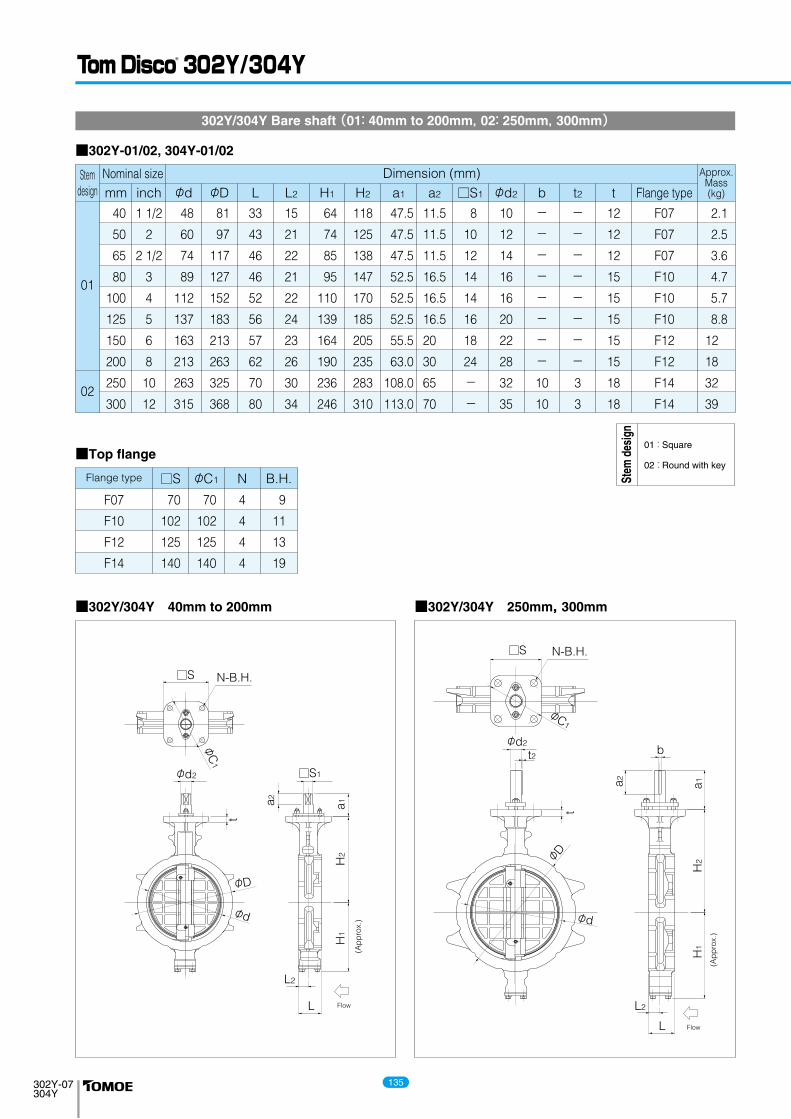
302Y/304Y Bare shaft (01: 40mm to 200mm, 02: 250mm, 300mm)
■302Y-01/02, 304Y-01/02
F07
F10
F12
F14
70
102
125
140
70
102
125
140
4
4
4
4
9
11
13
19
Flange type □S φC1 N B.H.
■Top flange
01
02
■302Y/304Y 250mm, 300mm■302Y/304Y 40mm to 200mm
02 : Round with key
01 : Square
Stem
des
ign
135
302Y-07304Y
φC
1
□S
□S1
N-B.H.
φd2
t
φd
φD
H1
H2
a1a2
L
L2
(Ap
pro
x.)
Flow
φC1
□S N-B.H.
φd2
t
φd
φD
t2
H1
H2
a1a2
b
L
L2
(Ap
pro
x.)
Flow
Dimension (mm)Nominal sizeStemdesign Flange type
Approx.Mass(kg)
40
50
65
80
100
125
150
200
250
300
1 1/2
2
2 1/2
3
4
5
6
8
10
12
48
60
74
89
112
137
163
213
263
315
81
97
117
127
152
183
213
263
325
368
15
21
22
21
22
24
23
26
30
34
64
74
85
95
110
139
164
190
236
246
118
125
138
147
170
185
205
235
283
310
33
43
46
46
52
56
57
62
70
80
47.5
47.5
47.5
52.5
52.5
52.5
55.5
63.0
108.0
113.0
11.5
11.5
11.5
16.5
16.5
16.5
20
30
65
70
--------10
10
12
12
12
15
15
15
15
15
18
18
10
12
14
16
16
20
22
28
32
35
8
10
12
14
14
16
18
24
--
F07
F07
F07
F10
F10
F10
F12
F12
F14
F14
2.1
2.5
3.6
4.7
5.7
8.8
12
18
32
39
mm inch φd φD L H1L2 H2 a1 a2 □S1 φd2 b
--------3
3
t2 t
302Y/304Y Bare shaft (01: 40mm to 200mm, 02: 250mm, 300mm)
■302Y-01/02, 304Y-01/02
F07
F10
F12
F14
70
102
125
140
70
102
125
140
4
4
4
4
9
11
13
19
Flange type □S φC1 N B.H.
■Top flange
01
02
■302Y/304Y 250mm, 300mm■302Y/304Y 40mm to 200mm
02 : Round with key
01 : Square
Stem
des
ign
302Y-08304Y
W
φD
LL2
φd
H3
H2
H1 Flow
Flow Flow Flow Flow
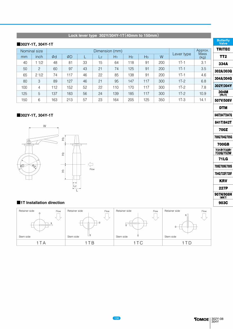
■302Y-1T, 304Y-1T
■302Y-1T, 304Y-1T
Dimension (mm)Nominal sizeLever type
Approx.Mass(kg)
40
50
65
80
100
125
150
1 1/2
2
2 1/2
3
4
5
6
48
60
74
89
112
137
163
81
97
117
127
152
183
213
15
21
22
21
22
24
23
64
74
85
95
110
139
164
118
125
138
147
170
185
205
33
43
46
46
52
56
57
91
91
91
117
117
117
125
200
200
200
300
300
300
350
1T-1
1T-1
1T-1
1T-2
1T-2
1T-2
1T-3
3.1
3.5
4.6
6.8
7.8
10.9
14.1
mm inch φd φD L H1L2 H2 H3 W
Lock lever type 302Y/304Y-1T(40mm to 150mm)
1 T A 1 T B 1 T C 1 T D
■1T Installation direction
Retainer side
Stem side
Retainer side
Stem side
Retainer side
Stem side
Retainer side
Stem side
136
ButterflyValve
TRITEC
TT2
334A
302A/303Q
304A/304Q
302Y/304Y
304M(HLV)
507V/508V
DTM
846T/847T/847Q
841T/842T
700Z
700G/704G/705G
700GB731P/732P/732Q/752W
71LG
700E/700K/700S
704G/722F/720F
KRV
227P
907H/908H(MKT)
903C

302Y-09304Y
φD
H1
H2
H3
L
L2
EK
φd
φW
F
Flow
FlowFlow
FlowFlow
Dimension (mm)Nominal size Gear typeApprox.
Mass(kg)
40
50
65
80
100
125
150
200
250
300
1 1/2
2
2 1/2
3
4
5
6
8
10
12
48
60
74
89
112
137
163
213
263
315
81
97
117
127
152
183
213
263
325
368
15
21
22
21
22
24
23
26
30
34
64
74
85
95
110
139
164
190
236
246
118
125
138
147
170
185
205
235
283
310
33
43
46
46
52
56
57
62
70
80
56
56
56
61
61
68
77.5
72
97
97
160
160
160
173.5
173.5
198
222.5
246
335
335
100
100
100
160
160
200
200
280
355
355
46
46
46
53
53
75
90
126
164
164
36
36
36
44
44
67
87.5
85
117
117
2U-0
2U-1
2U-1
2U-2
2U-2
2U-3
2U-4
DGH-2
DGH-3
DGH-3
5
5.4
6.5
7.6
8.6
18
28.5
38
69
76
mm inch φd φD L H1L2 H2 H3 E K F φW
Dimension (mm)Nominal size Gear typeApprox.
Mass(kg)
40
50
65
80
100
125
150
200
250
300
1 1/2
2
2 1/2
3
4
5
6
8
10
12
mm inch φd φD L H1L2 H2 H3 E K F φW
Worm gear type 302Y-2U(40mm to 150mm) / 302Y-2S (200mm to 300mm) / 304Y-2U(40mm to 300mm)
■302Y-2U(40mm to 150mm) / 2S (200mm to 300mm)
48
60
74
89
112
137
163
213
263
315
81
97
117
127
152
183
213
263
325
368
15
21
22
21
22
24
23
26
30
34
64
74
85
95
110
139
164
190
236
246
118
125
138
147
170
185
205
235
283
310
33
43
46
46
52
56
57
62
70
80
56
56
56
61
61
61
77.5
77.5
90
92
160
160
160
173.5
173.5
173.5
222.5
222.5
222.5
266
100
100
100
160
160
160
200
200
280
280
46
46
46
53
53
53
90
90
90
105
36
36
36
44
44
44
87.5
87.5
87.5
90
2U-0
2U-1
2U-1
2U-2
2U-2
2U-2
2U-4
2U-4
2U-4
2U-5
5
5.4
6.5
7.6
8.6
11.9
28.5
34.5
49.7
61
■304Y-2U
Retainer side
Stem side
Retainer side
Stem side
Retainer side
Stem side
Retainer side
Stem side
2 U A / 2 S A 2 U B / 2 S B
2 U C / 2 S C 2 U D / 2 S D
■2U/2S Installation direction■302Y-2U/2S■304Y-2U
137

302Y-09304Y
φD
H1
H2
H3
L
L2
EK
φd
φW
F
Flow
FlowFlow
FlowFlow
Dimension (mm)Nominal size Gear typeApprox.
Mass(kg)
40
50
65
80
100
125
150
200
250
300
1 1/2
2
2 1/2
3
4
5
6
8
10
12
48
60
74
89
112
137
163
213
263
315
81
97
117
127
152
183
213
263
325
368
15
21
22
21
22
24
23
26
30
34
64
74
85
95
110
139
164
190
236
246
118
125
138
147
170
185
205
235
283
310
33
43
46
46
52
56
57
62
70
80
56
56
56
61
61
68
77.5
72
97
97
160
160
160
173.5
173.5
198
222.5
246
335
335
100
100
100
160
160
200
200
280
355
355
46
46
46
53
53
75
90
126
164
164
36
36
36
44
44
67
87.5
85
117
117
2U-0
2U-1
2U-1
2U-2
2U-2
2U-3
2U-4
DGH-2
DGH-3
DGH-3
5
5.4
6.5
7.6
8.6
18
28.5
38
69
76
mm inch φd φD L H1L2 H2 H3 E K F φW
Dimension (mm)Nominal size Gear typeApprox.
Mass(kg)
40
50
65
80
100
125
150
200
250
300
1 1/2
2
2 1/2
3
4
5
6
8
10
12
mm inch φd φD L H1L2 H2 H3 E K F φW
Worm gear type 302Y-2U(40mm to 150mm) / 302Y-2S (200mm to 300mm) / 304Y-2U(40mm to 300mm)
■302Y-2U(40mm to 150mm) / 2S (200mm to 300mm)
48
60
74
89
112
137
163
213
263
315
81
97
117
127
152
183
213
263
325
368
15
21
22
21
22
24
23
26
30
34
64
74
85
95
110
139
164
190
236
246
118
125
138
147
170
185
205
235
283
310
33
43
46
46
52
56
57
62
70
80
56
56
56
61
61
61
77.5
77.5
90
92
160
160
160
173.5
173.5
173.5
222.5
222.5
222.5
266
100
100
100
160
160
160
200
200
280
280
46
46
46
53
53
53
90
90
90
105
36
36
36
44
44
44
87.5
87.5
87.5
90
2U-0
2U-1
2U-1
2U-2
2U-2
2U-2
2U-4
2U-4
2U-4
2U-5
5
5.4
6.5
7.6
8.6
11.9
28.5
34.5
49.7
61
■304Y-2U
Retainer side
Stem side
Retainer side
Stem side
Retainer side
Stem side
Retainer side
Stem side
2 U A / 2 S A 2 U B / 2 S B
2 U C / 2 S C 2 U D / 2 S D
■2U/2S Installation direction■302Y-2U/2S■304Y-2U
302Y-10304Y
L
L2
H3
H4
H2
H1
f1 f2A
P
φDφd
Flow
Flow Flow
Flow Flow
Air port side
Air port side
Air port sideAir port side
Double-acting pneumatic cylinder type 302Y-7E(40mm to 200mm) / 304Y-7E(40mm to 300mm)
Dimension (mm)Nominal sizeCylinder type
Approx.Mass(kg)
4050
65
80
100
125
150
200
1 1/22
2 1/2
3
4
5
6
8
4860
74
89
112
137
163
213
8197
117
127
152
183
213
263
1521
22
21
22
24
23
26
6474
85
95
110
139
164
190
118125
138
147
170
185
205
235
TL,TH
TL,TH
TL
TH
TL
TH
TL
TH
TL
TH
TL
TH
TL,TH
3343
46
46
52
56
57
62
142142142176142176176214176214214270270
47474757475757695769698585
276276276346276346346423346423423546546
168168168203168203203231203231231269269
T85T85T85
T200T85
T200T200T380T200T380T380T750T750
889
13111415211824283844
mm inch φd φD L H1L2 H2 H3
26.526.526.526.526.526.526.526.526.526.529.529.529.5
H4 A P7575757975797991799191
118118
f1 f2
■302Y-7E
4050
65
80
100
125150200
250
300
1 1/22
2 1/2
3
4
568
10
12
4860
74
89
112
137163213
263
315
8197
117
127
152
183213263
325
368
1521
22
21
22
242326
30
34
6474
85
95
110
139164190
236
246
118125
138
147
170
185205235
283
310
T10,T20
T10,T20
T10
T20
T10,T20
T10
T20
T10,T20
T10,T20
T10,T20
T10
T20
T10,T20
3343
46
46
52
565762
70
80
116116116142142142176176176214214270270
2929294747475757576987.587.587.5
228228228276276276346346346423423546546
125125125168168168203203203231231269269
T35T35T35T85T85T85
T200T200T200T380T380T750T750
5569
111215182234627279
26.526.526.526.526.526.526.526.529.529.5
190190190
5757577575757979799191
118118
■304Y-7E
7 E A 7 E B
7 E C 7 E D
■7E Installation direction
Retainer side
Stem side
Retainer side
Stem side
Retainer side
Stem side
Retainer side
Stem side
■302Y/304Y-7E
Category
Dimension (mm)Nominal sizeCylinder type
Approx.Mass(kg)mm inch φd φD L H1L2 H2 H3 H4 A P f1 f2Category
138
ButterflyValve
TRITEC
TT2
334A
302A/303Q
304A/304Q
302Y/304Y
304M(HLV)
507V/508V
DTM
846T/847T/847Q
841T/842T
700Z
700G/704G/705G
700GB731P/732P/732Q/752W
71LG
700E/700K/700S
704G/722F/720F
KRV
227P
907H/908H(MKT)
903C

302Y-11304Y
A
P
H2
H3
H1
φD φd
f1 f2
LL2
Flow
Flow Flow
Flow Flow
AP
φDφd φD
φd
AP
H1
H2
H3
H4
L
L2
f1 f2
Flow
Double-acting pneumatic cylinder type 302Y-3A (250, 300mm)
■302Y-3A
■302Y-3A
3 A A 3 A B
3 A C 3 A D
■3A Installation direction
Stem side
Retainer side
Stem side
Retainer side
Stem side
Retainer side
Stem side
Retainer side
■304A-7G■304A-7F
Dimension (mm)Nominal sizeCylinder type
Approx.Mass(kg)
250300
1012
263315
325368
3034
236246
283310
TL,TH
TL,TH
7080
381381
167167
754754
424424
TGA-125TGA-125
7885
mm inch φd φD L H1L2 H2 H3 A P7171
f1 f2Category
139
302Y-11304Y
A
P
H2
H3
H1
φD φd
f1 f2
LL2
Flow
Flow Flow
Flow Flow
AP
φDφd φD
φd
AP
H1
H2
H3
H4
L
L2
f1 f2
Flow
Double-acting pneumatic cylinder type 302Y-3A (250, 300mm)
■302Y-3A
■302Y-3A
3 A A 3 A B
3 A C 3 A D
■3A Installation direction
Stem side
Retainer side
Stem side
Retainer side
Stem side
Retainer side
Stem side
Retainer side
■304A-7G■304A-7F
Dimension (mm)Nominal sizeCylinder type
Approx.Mass(kg)
250300
1012
263315
325368
3034
236246
283310
TL,TH
TL,TH
7080
381381
167167
754754
424424
TGA-125TGA-125
7885
mm inch φd φD L H1L2 H2 H3 A P7171
f1 f2Category
302Y-12304Y
Air port side
Air port side
Air port sideAir port side
Air port side
Air port side
Air port sideAir port side
Flow Flow Flow Flow
Flow Flow Flow Flow
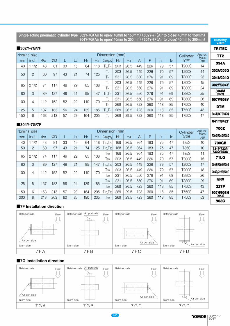
Single-acting pneumatic cylinder type 302Y-7G(Air to open: 40mm to 150mm) / 302Y-7F(Air to close: 40mm to 150mm) 304Y-7G(Air to open: 40mm to 200mm) / 304Y-7F(Air to close: 40mm to 200mm)
Dimension (mm)Nominal size Cylindertype
Approx.Mass(kg)
40
50
65
80
100
125150
1 1/2
2
2 1/2
3
4
56
48
60
74
89
112
137163
81
97
117
127
152
183213
15
21
22
21
22
2423
64
74
85
95
110
139164
118
125
138
147
170
185205
TL,TH
TL
TH
TL
TH
TL,TH
TL
TH
TL,TH
TL
33
43
46
46
52
5657
226226276226276276276360360360
57576957696969858585
449449550449550550550723723723
203203231203231231231269269269
T200ST200ST380ST200ST380ST380ST380ST750ST750ST750S
14142315242526404347
mm inch φd φD L H1L2 H2 H3
26.526.526.526.526.526.526.526.526.529.5
H4 A P79799179919191
118118118
f1 f2
■302Y-7G/7F
■304Y-7G/7F
7 F A 7 F B 7 F C 7 F D
■7F Installation direction
■7G Installation direction
Category
Dimension (mm)Nominal size Cylindertype
Approx.Mass(kg)mm inch φd φD L H1L2 H2 H3 H4 A P f1 f2Category
4050
65
80
100
125
150200
1 1/22
2 1/2
3
4
5
68
4860
74
89
112
137
163213
8197
117
127
152
183
213263
1521
22
21
22
24
2326
6474
85
95
110
139
164190
118125
138
147
170
185
205235
T10,T20
T10,T20
T10
T20
T10,T20
T10
T20
T10
T20
T10,T20
T10
3343
46
46
52
56
5762
183183183226226226276276360360360
4747475757576969858585
364364364449449449550550723723723
168168168203203203231231269269269
T85ST85ST85S
T200ST200ST200ST380ST380ST750ST750ST750S
1010111517182629434753
26.526.526.526.526.526.526.526.526.529.529.5
7575757979799191
118118118
Stem side
Retainer side
Stem side
Retainer side
Stem side
Retainer side
Stem side
Retainer side
7 G A 7 G B 7 G C 7 G D
Stem side
Retainer side
Stem side
Retainer side
Stem side
Retainer side
Stem side
Retainer side
140
ButterflyValve
TRITEC
TT2
334A
302A/303Q
304A/304Q
302Y/304Y
304M(HLV)
507V/508V
DTM
846T/847T/847Q
841T/842T
700Z
700G/704G/705G
700GB731P/732P/732Q/752W
71LG
700E/700K/700S
704G/722F/720F
KRV
227P
907H/908H(MKT)
903C

302Y-13304Y
AP
φDφd
AP
f1 f2
H1
H2
H3
L
L2
φDφd
Flow
Flow Flow Flow Flow
Flow Flow Flow Flow
150
200250300
6
81012
163
213263315
213
263325368
23
263034
164
190236246
205
235283310
TL
TH
TL,TH
TL,TH
TL,TH
57
627080
585720720865865
165206206257257
9451080108012551255
377377377450450
TG-10STG-12STG-12STG-14STG-14S
70116122238245
mm inch φd φD L H1L2 H2 H3 A P759494
131131
f1 f2
Single-acting pneumatic cylinder type 302Y-3U(Air to open: 150mm to 300mm) / 302Y-3K(Air to close: 150mm to 300mm) 304Y-3U(Air to open: 200mm to 300mm) / 304Y-3K(Air to close: 200mm to 300mm)
■302Y-3U/3K
200
250300
8
1012
213
263315
263
325368
26
3034
190
236246
235
283310
T10
T20
T10,T20
T10,T20
62
7080
585720720720
165206206206
945108010801080
377377417417
TG-10STG-12STG-12STG-12S
77122137144
75949494
■304Y-3U/3K
■302Y/304Y-3U■302Y/304Y-3K
■3U Installation direction
■3K Installation direction
3 K A 3 K B 3 K C 3 K D
Stem side
Retainer side
Stem side
Retainer side
Stem side
Retainer side
Stem side
Retainer side
3 U A 3 U B 3 U C 3 U D
Stem side
Retainer side
Stem side
Retainer side
Stem side
Retainer side
Stem side
Retainer side
Dimension (mm)Nominal size Cylindertype
Approx.Mass(kg)Category
mm inch φd φD L H1L2 H2 H3 A P f1 f2Dimension (mm)Nominal size Cylinder
type
Approx.Mass(kg)Category
141
302Y-13304Y
AP
φDφd
AP
f1 f2
H1
H2
H3
L
L2
φDφd
Flow
Flow Flow Flow Flow
Flow Flow Flow Flow
150
200250300
6
81012
163
213263315
213
263325368
23
263034
164
190236246
205
235283310
TL
TH
TL,TH
TL,TH
TL,TH
57
627080
585720720865865
165206206257257
9451080108012551255
377377377450450
TG-10STG-12STG-12STG-14STG-14S
70116122238245
mm inch φd φD L H1L2 H2 H3 A P759494
131131
f1 f2
Single-acting pneumatic cylinder type 302Y-3U(Air to open: 150mm to 300mm) / 302Y-3K(Air to close: 150mm to 300mm) 304Y-3U(Air to open: 200mm to 300mm) / 304Y-3K(Air to close: 200mm to 300mm)
■302Y-3U/3K
200
250300
8
1012
213
263315
263
325368
26
3034
190
236246
235
283310
T10
T20
T10,T20
T10,T20
62
7080
585720720720
165206206206
945108010801080
377377417417
TG-10STG-12STG-12STG-12S
77122137144
75949494
■304Y-3U/3K
■302Y/304Y-3U■302Y/304Y-3K
■3U Installation direction
■3K Installation direction
3 K A 3 K B 3 K C 3 K D
Stem side
Retainer side
Stem side
Retainer side
Stem side
Retainer side
Stem side
Retainer side
3 U A 3 U B 3 U C 3 U D
Stem side
Retainer side
Stem side
Retainer side
Stem side
Retainer side
Stem side
Retainer side
Dimension (mm)Nominal size Cylindertype
Approx.Mass(kg)Category
mm inch φd φD L H1L2 H2 H3 A P f1 f2Dimension (mm)Nominal size Cylinder
type
Approx.Mass(kg)Category
302Y-14304Y
KF
φDφd
P
A
H1
H2
H3
L
L2
Flow
Flow Flow
Flow Flow
40
50
65
80
100
125
150
200
250
300
1 1/2
2
2 1/2
3
4
5
6
8
10
12
48
60
74
89
112
137
163
213
263
315
81
97
117
127
152
183
213
263
325
368
15
21
22
21
22
24
23
26
30
34
64
74
85
95
110
139
164
190
236
246
118
125
138
147
170
185
205
235
283
310
TL,TH
TL,TH
TL
TH
TL,TH
TL,TH
TL,TH
TL,TH
TL,TH
TL,TH
TL(Remark)
TH
33
43
46
46
52
56
57
62
70
80
100
100
100
138
167
167
167
167
223
223
223
223
54
54
54
65
85
85
85
85
136
136
136
136
202
202
202
252
310
310
310
310
388
388
388
388
250
250
250
265
298
298
298
373
405
420
420
423
4 I-0
4 I-0
4 I-0
4 I-1
4 I-2
4 I-2
4 I-2
4 I-2.5
4 I-3
4 I-3
4 I-3
4 I-4
9.4
9.8
10.8
13
20
21
24
31
48
65
72
77
mm inch φd φD L H1L2 H2 H3 A P85
85
85
126
154
154
154
154
246
246
246
246
F K
48
60
74
89
112
137
163
213
263
315
81
97
117
127
152
183
213
263
325
368
15
21
22
21
22
24
23
26
30
34
64
74
85
95
110
139
164
190
236
246
118
125
138
147
170
185
205
235
283
310
T10,T20
T10,T20
T10,T20
T10,T20
T10
T20
T10,T20
T10,T20
T10,T20
T10
T20
T10,T20
33
43
46
46
52
56
57
62
70
80
100
100
100
100
138
167
167
167
167
167
223
223
54
54
54
54
65
85
85
85
85
85
136
136
202
202
202
202
252
310
310
310
310
310
388
388
250
250
250
250
265
298
298
373
373
411
420
420
4 I-0
4 I-0
4 I-0
4 I-0
4 I-1
4 I-2
4 I-2
4 I-2
4 I-2.5
4 I-2.5
4 I-3
4 I-3
9.4
9.8
10.8
11.8
15
21
24
29
38
55.5
65
72
85
85
85
85
126
154
154
154
154
154
246
246
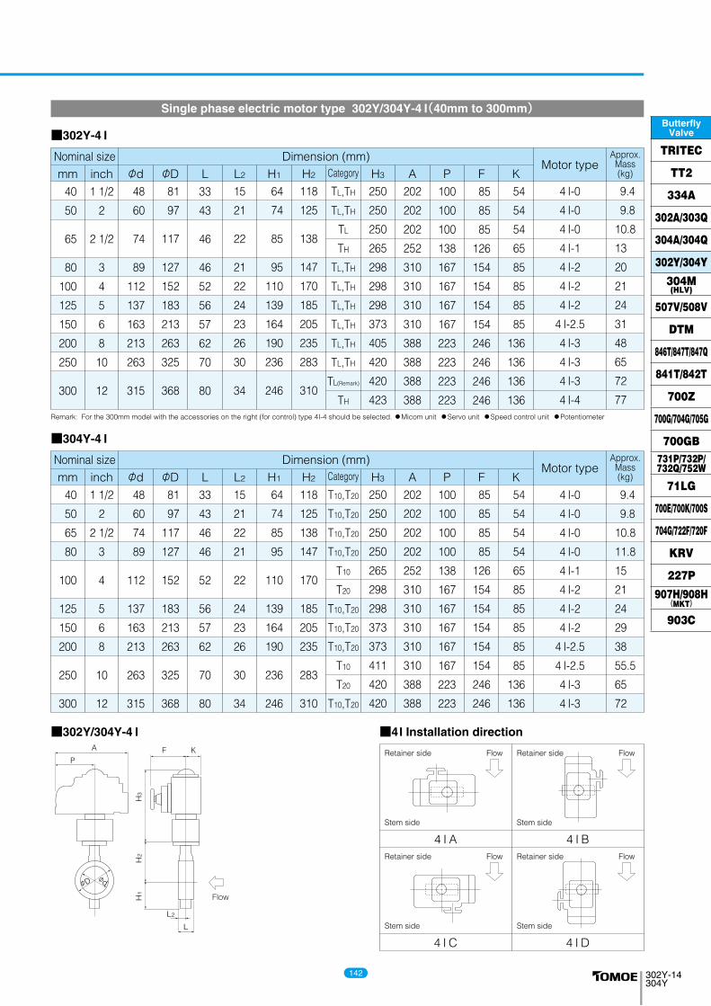
Remark: For the 300mm model with the accessories on the right (for control) type 4I-4 should be selected. ●Micom unit ●Servo unit ●Speed control unit ●Potentiometer
Single phase electric motor type 302Y/304Y-4 I(40mm to 300mm)
■302Y-4 I
■304Y-4 I
■302Y/304Y-4 I
4 I A 4 I B
4 I C 4 I D
■4I Installation direction
Stem side
Retainer side
Stem side
Retainer side
Stem side
Retainer side
Stem side
Retainer side
Dimension (mm)Nominal sizeMotor type
Approx.Mass(kg)Category
40
50
65
80
100
125
150
200
250
300
1 1/2
2
2 1/2
3
4
5
6
8
10
12
mm inch φd φD L H1L2 H2 H3 A P F KDimension (mm)Nominal size
Motor typeApprox.
Mass(kg)Category
142
ButterflyValve
TRITEC
TT2
334A
302A/303Q
304A/304Q
302Y/304Y
304M(HLV)
507V/508V
DTM
846T/847T/847Q
841T/842T
700Z
700G/704G/705G
700GB731P/732P/732Q/752W
71LG
700E/700K/700S
704G/722F/720F
KRV
227P
907H/908H(MKT)
903C

302Y-15304Y
L
L2
H3
H2
H1
φDφd
FE K
M P
Flow
Flow Flow Flow Flow
250
300
10
12
263
315
325
368
30
34
236
246
283
310
TL,TH
TL,TH
70
80
164
164
230
230
117
117
547
547
LTKD-01 0.2kW/DGH-3
LTKD-01 0.2kW/DGH-3
123
130
mm inch φd φD L H1L2 H2 H3 E K
533
533
F
357
357
M P
Three phase motor actuator type 302Y-4L(250mm, 300mm)
■302Y-4L
■302Y-4L
4 L A 4 L B 4 L C 4 L D
■4L Installation direction
Stem side
Retainer side
Stem side
Retainer side
Stem side
Retainer side
Stem side
Retainer side
Dimension (mm)Nominal size Motor typeApprox.
Mass(kg)Category
143
302Y-15304Y
L
L2
H3
H2
H1
φDφd
FE K
M P
Flow
Flow Flow Flow Flow
250
300
10
12
263
315
325
368
30
34
236
246
283
310
TL,TH
TL,TH
70
80
164
164
230
230
117
117
547
547
LTKD-01 0.2kW/DGH-3
LTKD-01 0.2kW/DGH-3
123
130
mm inch φd φD L H1L2 H2 H3 E K
533
533
F
357
357
M P
Three phase motor actuator type 302Y-4L(250mm, 300mm)
■302Y-4L
■302Y-4L
4 L A 4 L B 4 L C 4 L D
■4L Installation direction
Stem side
Retainer side
Stem side
Retainer side
Stem side
Retainer side
Stem side
Retainer side
Dimension (mm)Nominal size Motor typeApprox.
Mass(kg)Category
302Y-16304Y
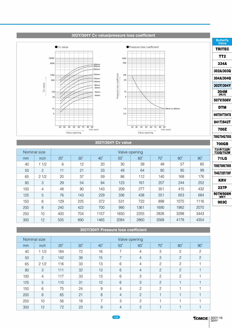
●Cv value ●Pressure loss coefficient
20°30° 40° 50° 60°70° 80°90°
10
5
100
50
1000
5000
10000
500
200mm
250mm300mm
150mm
125mm
100mm
80mm65mm
50mm
40mm
0.5
1.0
10
50
100
1000
500
5
40mm to 300mm
Pre
ssur
e lo
ss c
oeffi
cien
t
Cv
valu
e
Valve opening Valve opening(fully open)
20°30° 40° 50° 60°70° 80°90°(fully open)
Nominal size
mm inch 20° 30° 40° 50° 60° 70° 80° 90°40
50
65
80
100
125
150
200
250
300
1 1/2
2
2 1/2
3
4
5
6
8
10
12
6
11
20
29
48
76
129
240
400
505
12
21
37
54
90
143
225
422
704
890
20
33
59
84
143
229
372
700
1157
1465
30
49
86
123
209
336
531
990
1650
2084
39
64
112
161
277
438
722
1361
2255
2860
49
80
140
207
351
551
898
1690
2826
3568
57
95
168
244
415
653
1075
1982
3298
4178
60
99
176
252
432
684
1116
2070
3443
4354
Valve opening
Nominal size Valve opening
mm inch 20° 30° 40° 50° 60° 70° 80° 90°40
50
65
80
100
125
150
200
250
300
1 1/2
2
2 1/2
3
4
5
6
8
10
12
184
142
116
111
117
110
75
65
56
72
72
38
33
32
33
31
24
21
18
23
16
15
13
13
13
12
9
8
7
9
7
7
6
6
6
6
4
4
3
4
4
4
4
4
3
3
2
2
2
2
3
3
2
2
2
2
2
1
1
1
2
2
2
2
2
1
1
1
1
1
2
2
1
1
1
1
1
1
1
1
302Y/304Y Cv value/pressure loss coefficient
302Y/304Y Cv value
302Y/304Y Pressure loss coefficient
144
ButterflyValve
TRITEC
TT2
334A
302A/303Q
304A/304Q
302Y/304Y
304M(HLV)
507V/508V
DTM
846T/847T/847Q
841T/842T
700Z
700G/704G/705G
700GB731P/732P/732Q/752W
71LG
700E/700K/700S
704G/722F/720F
KRV
227P
907H/908H(MKT)
903C

302Y-17304Y
t
tMinimum internaldiameter of piping
A
Minimum internaldiameter of piping
B
Stem side Retainer side
Flow
Nominalsize
40
50
65
80
100
125
150
200
250
300
1 1/2
2
2 1/2
3
4
5
6
8
10
12
○○○○○○○○○○
mm inchRetainer
(up stream)
○○○○○○○○○○
Stem Side(down stream)
-○○○○○○○○○
Retainer(up stream)
-○○○○○○○○○
Stem Side(down stream)
○○○○○○○○○○
Retainer(up stream)
○○○○○○○○○○
Stem Side(down stream)
○○○○○○○○○○
Retainer(up stream)
○○○○○○××××
Stem Side(down stream)
○○○○○○○○○×
Retainer(up stream)
○○○○○○××××
Stem Side(down stream)
○○○○○○○○○○
Retainer(up stream)
○○○○○○○○○○
Stem Side(down stream)
○○○○○○○○○○
Retainer(up stream)
○○○○○○○○○○
Stem Side(down stream)
32.7
34.6
53.6
72.5
93.8
119.4
147.5
197.5
248.1
297.6
Minimuminternal
diametersof piping
(mm)
20.0
25.0
40.0
63.6
87.0
112.8
142.5
193.3
248.1
297.6
Minimuminternal
diametersof piping
(mm)
Sch20SGP Sch40 Sch60 Sch80 Sch10S Sch20S
Nominalsize
40
50
65
80
100
125
150
200
250
300
1 1/2
2
2 1/2
3
4
5
6
8
10
12
mm inchRetainer
(up stream)Stem Side
(down stream)Retainer
(up stream)Stem Side
(down stream)Retainer
(up stream)Stem Side
(down stream)Retainer
(up stream)Stem Side
(down stream)Retainer
(up stream)Stem Side
(down stream)Retainer
(up stream)Stem Side
(down stream)Retainer
(up stream)Stem Side
(down stream)
Sch20SGP Sch40 Sch60 Sch80 Sch10S Sch20S
Remark 1: ○=Applicable ×=Not applicableRemark 2: The clearance between the disc and the pipe is based on API 609 and MSS SP-67. 40mm to 150mm: 1.5mm; 200mm to 300mm: 3.0mmRemark 3: Butterfly valves are inserted into a pipe that was fitted with the disc when fully open. In cases where there is an “X” in the chart above or you are using a pipe or flange that is less than the minimum inner pipe diameter, use is still possible if means are taken such as inserting a spacer between the valve and flange. For details, please consult us.
○○○○○○○○○○
○○○○○○○○○○
-○○○○○○○○○
-○○○○○○○○○
○○○○○○○○○○
○○○○○○○○○○
○○○○○○○○○○
○○○○○○○×××
○○○○○○○○○○
○○○○○○○×××
○○○○○○○○○○
○○○○○○○○○○
○○○○○○○○○○
○○○○○○○○○○
302Y/304Y Applicable pipe list in case of A
302Y/304Y Applicable pipe list in case of B
145
302Y-17304Y
t
tMinimum internaldiameter of piping
A
Minimum internaldiameter of piping
B
Stem side Retainer side
Flow
Nominalsize
40
50
65
80
100
125
150
200
250
300
1 1/2
2
2 1/2
3
4
5
6
8
10
12
○○○○○○○○○○
mm inchRetainer
(up stream)
○○○○○○○○○○
Stem Side(down stream)
-○○○○○○○○○
Retainer(up stream)
-○○○○○○○○○
Stem Side(down stream)
○○○○○○○○○○
Retainer(up stream)
○○○○○○○○○○
Stem Side(down stream)
○○○○○○○○○○
Retainer(up stream)
○○○○○○××××
Stem Side(down stream)
○○○○○○○○○×
Retainer(up stream)
○○○○○○××××
Stem Side(down stream)
○○○○○○○○○○
Retainer(up stream)
○○○○○○○○○○
Stem Side(down stream)
○○○○○○○○○○
Retainer(up stream)
○○○○○○○○○○
Stem Side(down stream)
32.7
34.6
53.6
72.5
93.8
119.4
147.5
197.5
248.1
297.6
Minimuminternal
diametersof piping
(mm)
20.0
25.0
40.0
63.6
87.0
112.8
142.5
193.3
248.1
297.6
Minimuminternal
diametersof piping
(mm)
Sch20SGP Sch40 Sch60 Sch80 Sch10S Sch20S
Nominalsize
40
50
65
80
100
125
150
200
250
300
1 1/2
2
2 1/2
3
4
5
6
8
10
12
mm inchRetainer
(up stream)Stem Side
(down stream)Retainer
(up stream)Stem Side
(down stream)Retainer
(up stream)Stem Side
(down stream)Retainer
(up stream)Stem Side
(down stream)Retainer
(up stream)Stem Side
(down stream)Retainer
(up stream)Stem Side
(down stream)Retainer
(up stream)Stem Side
(down stream)
Sch20SGP Sch40 Sch60 Sch80 Sch10S Sch20S
Remark 1: ○=Applicable ×=Not applicableRemark 2: The clearance between the disc and the pipe is based on API 609 and MSS SP-67. 40mm to 150mm: 1.5mm; 200mm to 300mm: 3.0mmRemark 3: Butterfly valves are inserted into a pipe that was fitted with the disc when fully open. In cases where there is an “X” in the chart above or you are using a pipe or flange that is less than the minimum inner pipe diameter, use is still possible if means are taken such as inserting a spacer between the valve and flange. For details, please consult us.
○○○○○○○○○○
○○○○○○○○○○
-○○○○○○○○○
-○○○○○○○○○
○○○○○○○○○○
○○○○○○○○○○
○○○○○○○○○○
○○○○○○○×××
○○○○○○○○○○
○○○○○○○×××
○○○○○○○○○○
○○○○○○○○○○
○○○○○○○○○○
○○○○○○○○○○
302Y/304Y Applicable pipe list in case of A
302Y/304Y Applicable pipe list in case of B
302Y-18304Y
4.5
D1
D2
D3
D4
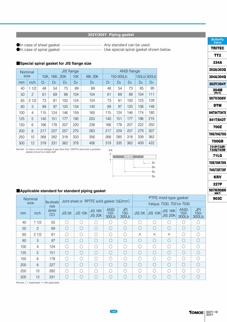
Remark : In case a minute leakage of gas (less than 100PPm) becomes a problem, please consult our sales staff.
302Y/304Y Piping gasket
10K, 16K, 20K 16K, 20K10K 150-300Lb 300Lb150Lb
40
50
65
80
100
125
150
200
250
300
48
61
73
89
115
140
166
217
268
319
mm inch D1 D2 D3 D4 D1 D2 D3 D4 D4D4
■Special spiral gasket for JIS flange size
1 1/2
2
2 1/2
3
4
5
6
8
10
12
54
69
81
97
124
151
178
227
282
331
73
88
100
120
146
177
207
257
318
362
89
104
124
134
159
190
220
270
333
378
89
104
124
140
165
203
238
283
356
406
48
61
73
89
115
140
166
217
268
319
54
69
81
97
124
151
178
229
285
335
73
88
100
120
146
177
207
257
318
362
85
104
123
136
174
196
222
279
339
409
95
111
129
148
180
215
250
307
362
422
ANSI flange
Nominalsize Joint sheet or RPTFE solid gasket (t≦2mm)
PTFE mold type gasket
Valqua: 7030, 7031or 7035
40
50
65
80
100
125
150
200
250
300
55
69
81
97
124
151
178
227
282
331
○○○○○○○○○○
mm inch
Max.allowableinside
diameter(D) JIS 5K JIS 10K
JIS 16KJIS 20K
ANSI150-
300Lb
JPI150-
300LbJIS 5K JIS 10K
JIS 16KJIS 20K
ANSI150-
300Lb
JPI150-
300Lb
■Applicable standard for standard piping gasket
1 1/2
2
2 1/2
3
4
5
6
8
10
12
○○○○○○○○○○
○○○○○○○○○○
○○○○○○○○○○
○○○○○○○○○○
○○×○○○○○○○
○○×○○○○○○○
○○×○○○○○○○
○○○○○○○○○○
○○○○○○○○○○
Remark; ○: Applicable, ×: Not applicable
Nominalsize
●In case of sheet gasket●In case of spiral gasket
Any standard can be used.Use special spiral gasket shown below.
JIS flange
146
ButterflyValve
TRITEC
TT2
334A
302A/303Q
304A/304Q
302Y/304Y
304M(HLV)
507V/508V
DTM
846T/847T/847Q
841T/842T
700Z
700G/704G/705G
700GB731P/732P/732Q/752W
71LG
700E/700K/700S
704G/722F/720F
KRV
227P
907H/908H(MKT)
903C
302Y-19304Y
L
M
Long bolts and nuts (full thread)
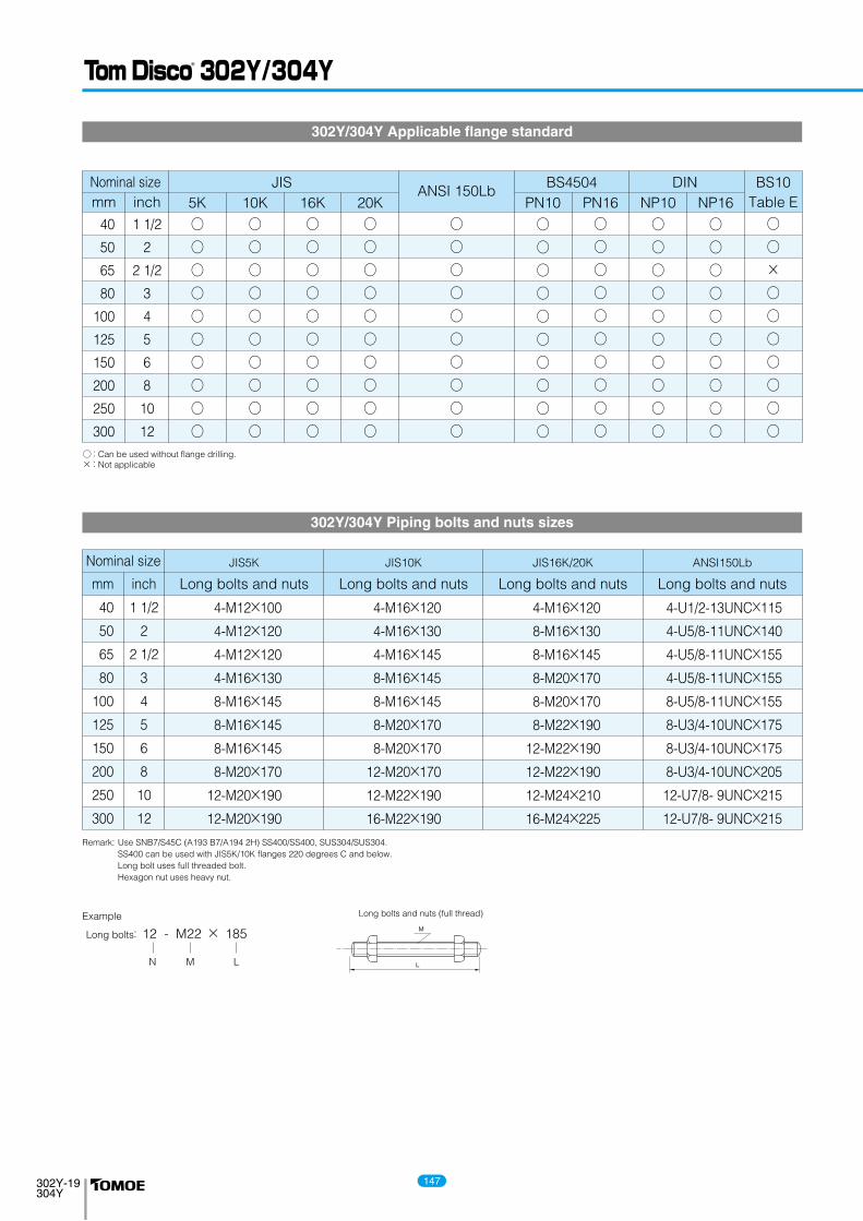
JIS ANSI 150Lb
BS4504 DIN BS10Nominal size
40
50
65
80
100
125
150
200
250
300
1 1/2
2
2 1/2
3
4
5
6
8
10
12
○○○○○○○○○○
○○○○○○○○○○
○○○○○○○○○○
○○○○○○○○○○
○○○○○○○○○○
○○×○○○○○○○
○○○○○○○○○○
mm inch 5K 10K 20K16K
○○○○○○○○○○
PN10 PN16
○○○○○○○○○○
○○○○○○○○○○
NP10 NP16 Table E
302Y/304Y Piping bolts and nuts sizes
Remark: Use SNB7/S45C (A193 B7/A194 2H) SS400/SS400, SUS304/SUS304. SS400 can be used with JIS5K/10K flanges 220 degrees C and below. Long bolt uses full threaded bolt. Hexagon nut uses heavy nut.
Nominal size
40
50
65
80
100
125
150
200
250
300
4-M12×100
4-M12×120
4-M12×120
4-M16×130
8-M16×145
8-M16×145
8-M16×145
8-M20×170
12-M20×190
12-M20×190
4-M16×120
4-M16×130
4-M16×145
8-M16×145
8-M16×145
8-M20×170
8-M20×170
12-M20×170
12-M22×190
16-M22×190
4-M16×120
8-M16×130
8-M16×145
8-M20×170
8-M20×170
8-M22×190
12-M22×190
12-M22×190
12-M24×210
16-M24×225
4-U1/2-13UNC×115
4-U5/8-11UNC×140
4-U5/8-11UNC×155
4-U5/8-11UNC×155
8-U5/8-11UNC×155
8-U3/4-10UNC×175
8-U3/4-10UNC×175
8-U3/4-10UNC×205
12-U7/8- 9UNC×215
12-U7/8- 9UNC×215
mm inch Long bolts and nuts Long bolts and nuts Long bolts and nuts Long bolts and nuts
JIS5K JIS10K JIS16K/20K ANSI150Lb
1 1/2
2
2 1/2
3
4
5
6
8
10
12
○ : Can be used without flange drilling. × : Not applicable
Long bolts: 12 - M22 × 185
N M L
Example
302Y/304Y Applicable flange standard
147