general rbm procedure richards bay minerals
TRANSCRIPT

This printed copy is only valid for 11/02/2019
RICHARDS BAY MINERALS
GENERAL RBM PROCEDURE
Effective date: 17 February 2019
Applicable to Procedure No. Revision No. Page
All divisions E 28 GP 001 14 1 of 20
WORKING AT HEIGHTS – SCAFFOLDING STANDARDS
Compiled By: Engineer Reliability
1. OBJECTIVE
This General Procedure serves to ensure that there is common understanding around the use of scaffolding, especially how scaffolding is assembled, inspected, used, and maintained in accordance with legislation and accepted corporate safety standards. A scaffold is a temporary construction that consists of a framework and an elevated working platform for supporting men, and a limited weight of equipment and materials.
2. SCOPE .
This procedure covers definitions used, responsibilities, and construction standards for different types of scaffolding and includes the numbering, storage, assembly, maintenance and inspection of scaffolding. While it intends to highlight pertinent aspects from SANS 10085-1:2004, it is by no means a substitute for the code and all user, erectors and requestors of scaffolding must familiarise themselves with this code.
3. ROLES AND RESPONSIBILITIES 3.1 The requester shall complete the Scaffolding request in SAP in all cases and ensure that no
work is carried out without the Notification of Presence (NOP) 3.2 The Responsible Scaffolding Supervisor must ensure that every scaffold is erected, maintained
and dismantled by a person who has had adequate training and experience in such work and that the work is carried out under the supervision of a competent person. Where a contract company is tasked to carry out scaffolding erection, the company must have the minimum requirement of a NOSA 3-star rating.
3.3 The appointed RBM responsible person / engineer is responsible for ensuring that:
a. The “User”, as per SANS 10085-1; 2004 section 15, is aware of his responsibilities, and has completed the required training and been appointed as a “User”.
b. An inspection of ALL exposed erected scaffolding (whether handed over or not) is carried
out after periods of inclement weather such as heavy rains and strong wind, as defined in item 17.5. b) and the inspection must be recorded in the log for the scaffold. The Scaffold Log’s to be initiated on erection of the scaffold and terminated when the scaffold is dismantled both dates inclusive.
c. A safety harness, with double shock absorbing lanyards, not exceeding 2 metres (yellow in
colour), shall be used by any person erecting, modifying or dismantling a scaffold (where the potential to fall is greater than 5 meters) or 1 meter short restraining lanyards (red in colour,) (where the potential to fall is less than 5 meters). Inertia type fall arrest devices, of approved type, may be used where there is no risk that the person will come in contact with the ground in the event of a fall.
E 28 GP 001 REV NO: 14 PAGE 2 OF 20
This printed copy is only valid for 11/02/2019
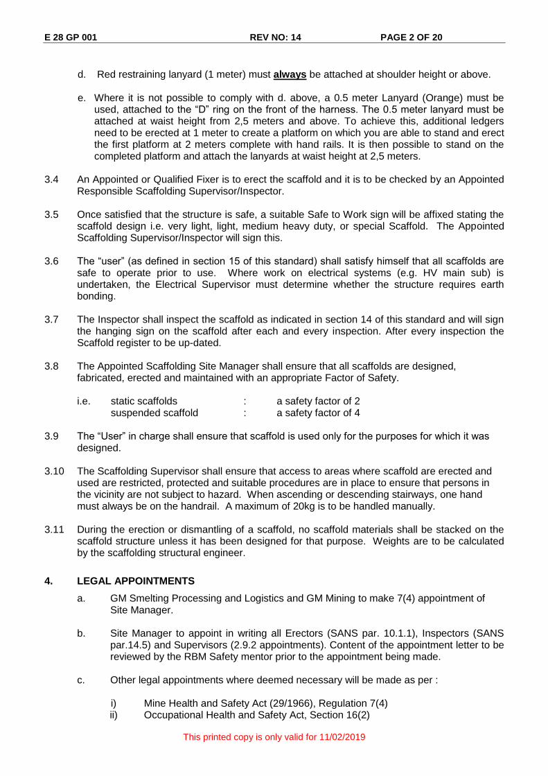
d. Red restraining lanyard (1 meter) must always be attached at shoulder height or above.
e. Where it is not possible to comply with d. above, a 0.5 meter Lanyard (Orange) must be
used, attached to the “D” ring on the front of the harness. The 0.5 meter lanyard must be attached at waist height from 2,5 meters and above. To achieve this, additional ledgers need to be erected at 1 meter to create a platform on which you are able to stand and erect the first platform at 2 meters complete with hand rails. It is then possible to stand on the completed platform and attach the lanyards at waist height at 2,5 meters.
3.4 An Appointed or Qualified Fixer is to erect the scaffold and it is to be checked by an Appointed
Responsible Scaffolding Supervisor/Inspector. 3.5 Once satisfied that the structure is safe, a suitable Safe to Work sign will be affixed stating the
scaffold design i.e. very light, light, medium heavy duty, or special Scaffold. The Appointed Scaffolding Supervisor/Inspector will sign this.
3.6 The “user” (as defined in section 15 of this standard) shall satisfy himself that all scaffolds are
safe to operate prior to use. Where work on electrical systems (e.g. HV main sub) is undertaken, the Electrical Supervisor must determine whether the structure requires earth bonding.
3.7 The Inspector shall inspect the scaffold as indicated in section 14 of this standard and will sign
the hanging sign on the scaffold after each and every inspection. After every inspection the Scaffold register to be up-dated.
3.8 The Appointed Scaffolding Site Manager shall ensure that all scaffolds are designed,
fabricated, erected and maintained with an appropriate Factor of Safety.
i.e. static scaffolds : a safety factor of 2 suspended scaffold : a safety factor of 4
3.9 The “User” in charge shall ensure that scaffold is used only for the purposes for which it was
designed. 3.10 The Scaffolding Supervisor shall ensure that access to areas where scaffold are erected and
used are restricted, protected and suitable procedures are in place to ensure that persons in the vicinity are not subject to hazard. When ascending or descending stairways, one hand must always be on the handrail. A maximum of 20kg is to be handled manually.
3.11 During the erection or dismantling of a scaffold, no scaffold materials shall be stacked on the
scaffold structure unless it has been designed for that purpose. Weights are to be calculated by the scaffolding structural engineer.
4. LEGAL APPOINTMENTS
a. GM Smelting Processing and Logistics and GM Mining to make 7(4) appointment of Site Manager.
b. Site Manager to appoint in writing all Erectors (SANS par. 10.1.1), Inspectors (SANS par.14.5) and Supervisors (2.9.2 appointments). Content of the appointment letter to be reviewed by the RBM Safety mentor prior to the appointment being made.
c. Other legal appointments where deemed necessary will be made as per :
i) Mine Health and Safety Act (29/1966), Regulation 7(4) ii) Occupational Health and Safety Act, Section 16(2)
E 28 GP 001 REV NO: 14 PAGE 3 OF 20
This printed copy is only valid for 11/02/2019
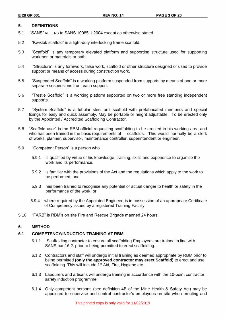
5. DEFINITIONS
5.1 “SANS” REFERS to SANS 10085-1:2004 except as otherwise stated. 5.2 “Kwiklok scaffold” is a light-duty interlocking frame scaffold. 5.3 “Scaffold” is any temporary elevated platform and supporting structure used for supporting
workmen or materials or both. 5.4 “Structure” is any formwork, false work, scaffold or other structure designed or used to provide
support or means of access during construction work. 5.5 “Suspended Scaffold” is a working platform suspended from supports by means of one or more
separate suspensions from each support. 5.6 “Trestle Scaffold” is a working platform supported on two or more free standing independent
supports. 5.7 “System Scaffold” is a tubular steel unit scaffold with prefabricated members and special
fixings for easy and quick assembly. May be portable or height adjustable. To be erected only by the Appointed / Accredited Scaffolding Contractor.
5.8 “Scaffold user” is the RBM official requesting scaffolding to be erected in his working area and
who has been trained in the basic requirements of scaffolds. This would normally be a clerk of works, planner, supervisor, maintenance controller, superintendent or engineer.
5.9 “Competent Person” is a person who 5.9.1 is qualified by virtue of his knowledge, training, skills and experience to organise the
work and its performance. 5.9.2 is familiar with the provisions of the Act and the regulations which apply to the work to
be performed; and
5.9.3 has been trained to recognise any potential or actual danger to health or safety in the performance of the work; or
5.9.4 where required by the Appointed Engineer, is in possession of an appropriate Certificate of Competency issued by a registered Training Facility.
5.10 “FARB” is RBM’s on site Fire and Rescue Brigade manned 24 hours.
6. METHOD
6.1 COMPETENCY/INDUCTION TRAINING AT RBM
6.1.1 Scaffolding contractor to ensure all scaffolding Employees are trained in line with SANS par.16.2. prior to being permitted to erect scaffolding.
6.1.2 Contractors and staff will undergo initial training as deemed appropriate by RBM prior to
being permitted (only the approved contractor may erect Scaffold) to erect and use scaffolding. This will include 1st Aid, Fire, Hygiene etc.
6.1.3 Labourers and artisans will undergo training in accordance with the 10-point contractor
safety induction programme. 6.1.4 Only competent persons (see definition 4B of the Mine Health & Safety Act) may be
appointed to supervise and control contractor’s employees on site when erecting and

E 28 GP 001 REV NO: 14 PAGE 4 OF 20
This printed copy is only valid for 11/02/2019
dismantling of scaffolding. 6.1.5 The Appointed Scaffolding Contractor to have a NOSA 3-Star rating (or equivalent) and
have action plans to achieve a higher rating. 6.1.6 Where required by the appointed RBM Responsible Person / Engineer, Scaffolding
employees appointed will be in possession of an appropriate Certificate of Competency issued by a registered Training Facility.
7. TRANSPORTATION AND HANDLING OF SCAFFOLD COMPONENTS
7.1 The Appointed Contractor must transport scaffold materials using a method of conveyance in accordance with COP 70 and RT C3 vehicles/driving standards. Vehicle drawn road trailers must comply with the SOP 70.1 through 70.6.
7.2 When scaffold components are to be erected in elevated areas, the entire work area including
ground floor areas are to be barricaded to prevent persons entering the work zone. 7.3 Hoists, lifts and approved material baskets must be used (where available) to raise scaffold
components to elevated areas. All lifting equipment used must comply with COP 29: Lifting Equipment and Machinery. Engineering certification is required for material baskets.
7.4 Where components are handled manually, E29 GP 003 - SAFE MANUAL LIFTING
OPERATIONS must be followed. All scaffold braces (pipes and tubes), which equals or exceeds a length of 4 metres (difficult to handle), must be equipped with protective end caps. The end cap serves the purpose of effectively preventing a person’s finger from entering the cavity and removes the sharp edge. The endcap engagement section need to be serrated, so that it would be very difficult to remove once installed. Refer to Appendix 7 for example. It is not required for standards and ledgers.
7.5 Whilst erecting and dismantling a scaffold and components are being passed hand to hand the
scaffolder’s are to always stand on 3 boards and not directly above the person below. Stay within the confines of the scaffold and expose the least amount of your body as possible during the process. Good communication between team members must be maintained at all times. All members of the team need to know what the means of communication is i.e. verbal or in a high
noise area eye contact and/ or body language. When handling cross brasses, standards and all scaffold ‘fittings’ and connections they should be removed or securely tightened before erection and dismantling to prevent injury. EG Fixed couplings Swivel joints, swingover bolts, Tube clamps,. Clamps and brackets.
7.6 Where the height of the scaffold is 6m and above (more than 2 levels high), the scaffolding
must be planned and erected in such a way that the guideline as in Appendix 6 - Arrangement of Protective Shield, is in place during erection, modification and dismantling of the scaffolding. This protective shield must also be in place during the period that the scaffolding is handed over to the USER of the scaffolding. This protective shield, it’s direction and it’s length must be erected in such a way that it ensures that, if an item falls from the scaffolding, all persons below who may be in the line of falling items, will be protected by the steel scaffold boards above. The length of the tunnel (shield) must be adequate to take people far enough from the zone where items may fall or bounce to. A practical guideline is that the shield must be 1/3 of the height of the scaffolding away from the scaffold or position from where items may fall from the scaffolding during erection and use.
7.7 The barricading arrangement around the scaffolding and the protective shield must further
ensure that no one can enter the “NO GO zone” created by the barricading. The exact layout of the Protective Canopy and the barricading may have to change during the period that the scaffold is handed over to the user (and changed back again for dismantling).
E 28 GP 001 REV NO: 14 PAGE 5 OF 20
This printed copy is only valid for 11/02/2019
7.8 The safety zone (shield) and no go areas must be planned and hazards (falling items)
assessed to ensure all person at all times (Scaffolders and Users) are provided with adequate protection from falling items by keeping people out of the NO GO areas around the scaffolding and providing them with a safe passage under the protective shield to erect, modify, dismantle or access the scaffolding.
7.9 Tools to be secured to the wrist, harness or structure by a lanyard, or in a tool bag for lowering
or raising from elevated work areas. A rope must be used for lifting and lowering equipment in cases where both hands must be used for climbing.
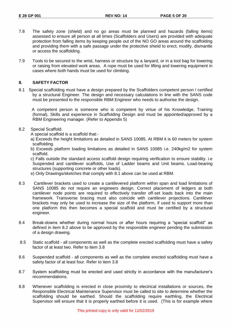
8. SAFETY FACTOR
8.1 Special scaffolding must have a design prepared by the Scaffolders competent person / certified by a structural Engineer. The design and necessary calculations in line with the SANS code must be presented to the responsible RBM Engineer who needs to authorise the design.
A competent person is someone who is competent by virtue of his Knowledge, Training
(formal), Skills and experience in Scaffolding Design and must be appointed/approved by a RBM Engineering manager. (Refer to Appendix 5)
8.2 Special Scaffold. A special scaffold is a scaffold that:- a) Exceeds the height limitations as detailed in SANS 10085. At RBM it is 60 meters for system
scaffolding. b) Exceeds platform loading limitations as detailed in SANS 10085 i.e. 240kg/m2 for system
scaffold. c) Falls outside the standard access scaffold design requiring verification to ensure stability. i.e
Suspended and cantilever scaffolds, Use of Ladder beams and Unit beams. Load-bearing structures (supporting concrete or other loads).
e) Only Drawings/sketches that comply with 8.1 above can be used at RBM. 8.3 Cantilever brackets used to create a cantilevered platform within span and load limitations of
SANS 10085 do not require an engineers design. Correct placement of ledgers at both cantilever node points are required to effectively transfer off-set loads back into the main framework. Transverse bracing must also coincide with cantilever projections. Cantilever brackets may only be used to increase the size of the platform, if used to support more than one platform this then becomes a special scaffold and must be certified by a structural engineer.
8.4 Break-downs whether during normal hours or after hours requiring a “special scaffold” as
defined in item 8.2 above to be approved by the responsible engineer pending the submission of a design drawing.
8.5 Static scaffold - all components as well as the complete erected scaffolding must have a safety
factor of at least two. Refer to item 3.8 8.6 Suspended scaffold - all components as well as the complete erected scaffolding must have a
safety factor of at least four. Refer to item 3.8 8.7 System scaffolding must be erected and used strictly in accordance with the manufacturer’s
recommendations. 8.8 Whenever scaffolding is erected in close proximity to electrical installations or sources, the
Responsible Electrical Maintenance Supervisor must be called to site to determine whether the scaffolding should be earthed. Should the scaffolding require earthling, the Electrical Supervisor will ensure that it is properly earthed before it is used. (This is for example where

E 28 GP 001 REV NO: 14 PAGE 6 OF 20
This printed copy is only valid for 11/02/2019
work is executed in the HV Main sub – Power Operations).
9. SCAFFOLDING ACCESS LADDER
9.1 In the case of scaffolding with vertical ladder access the requirements for a cage may be waived, provided the rest platforms shall be provided at intervals not exceeding 4 meters with the vertical ladder secured on the inside of the scaffolding framework and the opening in the platform closed with a trap-door.
9.2 In the case of scaffolding which is to narrow i.e. 770mm to allow the use of a Trap-door the
ladder to be mounted externally and a cage must be erected 700mm from the rungs of the ladder and 700mm wide extending 2 meters from the base of the ladder to a point 900mm beyond the resting platform. Not to exceed 4 meters between rest platforms and the access from the platform to the ladder closed with a chain.
9.3 The ladder should extend at least 900mm above the inside landing or platform to be reached.
9.4 The access ladder shall be firmly supported at the base and secured in position with fastenings
of a strength greater than that of the strings.
10. SCAFFOLD ERECTION
10.1 Scaffolding shall not be:
erected when raining
erected in winds above 35km/h
10.2 Scaffold erected on grating:
Where the plant design permits and a standard needs to be erected on the grating, the grating will be supported underneath with another standard and jack fitted at the top and screwed tight. When a support cannot be erected underneath the grating, the scaffold must be supported on the structure that supports the grating.
Deviations to the above conditions must be approved by the relevant plant engineer.
10.3 Stay within the confines of the scaffold while erecting. 10.4 Where required by risk assessment a detailed plan must be provided for erection and
dismantling with reference to appendix 4 and 6.
11 SCAFFOLD PLATFORMS
11.1 Work platforms must consist of suitable metal scaffold boards. 11.2 Metal scaffold boards provided with toe boards must be fitted so that hooking devices are
properly secured to the Ledgers/transoms. 11.3 Wooden boards when and if used, as platforms must have the ends banded with steel strips to
prevent splitting. Nowadays wooden boards are rarely used and metal boards preferred 11.4 Every plank of a solid wooden scaffold platform must be at least 38mm thick. If scaffold boards
of other dimensions are used, spacing of supports and overhang must be in accordance with SANS 10085-1: 2004
11.5 Every timber scaffold board of 38mm thick must be supported at distances not exceeding 1, 25
metres with the overhang no less than 70mm and not exceeding 150mm. 11.6 Each board must be separately secured to the scaffold structure.
E 28 GP 001 REV NO: 14 PAGE 7 OF 20
This printed copy is only valid for 11/02/2019
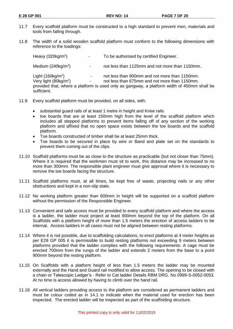
11.7 Every scaffold platform must be constructed to a high standard to prevent men, materials and tools from falling through.
11.8 The width of a solid wooden scaffold platform must conform to the following dimensions with
reference to the loadings:
Heavy (320kg/m2) - To be authorised by certified Engineer.
Medium (240kg/m2) - not less than 1125mm and not more than 1150mm.
Light (160kg/m2) - not less than 900mm and not more than 1150mm. Very light (80kg/m2) - not less than 675mm and not more than 1150mm. provided that, where a platform is used only as gangway, a platform width of 450mm shall be sufficient.
11.9 Every scaffold platform must be provided, on all sides, with:
substantial guard rails of at least 1 metre in height and Knee rails
toe boards that are at least 150mm high from the level of the scaffold platform which includes all stepped platforms to prevent items falling off of any section of the working platform and affixed that no open space exists between the toe boards and the scaffold platform.
Toe boards constructed of timber shall be at least 25mm thick.
Toe boards to be secured in place by wire or Band and plate set on the standards to prevent them coming out of the clips.
11.10 Scaffold platforms must be as close to the structure as practicable (but not closer than 75mm).
Where it is required that the workmen must sit to work, this distance may be increased to no more than 300mm. The responsible plant engineer must give approval where it is necessary to remove the toe boards facing the structure.
11.11 Scaffold platforms must, at all times, be kept free of waste, projecting nails or any other
obstructions and kept in a non-slip state. 11.12 No working platform greater than 600mm in height will be supported on a scaffold platform
without the permission of the Responsible Engineer. 11.13 Convenient and safe access must be provided to every scaffold platform and where the access
is a ladder, the ladder must project at least 900mm beyond the top of the platform. On all Scaffolds with a platform height of more than 1.5 meters the erection of access ladders to be internal. Access ladders in all cases must not be aligned between resting platforms.
11.14 Where it is not possible, due to scaffolding calculations, to erect platforms at 4 meter heights as
per E28 GP 005 it is permissible to build resting platforms not exceeding 9 meters between platforms provided that the ladder complies with the following requirements: A cage must be erected 700mm from the rungs of the ladder and extends 2 meters from the base to a point 900mm beyond the resting platform.
11.15 On Scaffolds with a platform height of less than 1.5 meters the ladder may be mounted
externally and the Hand and Guard rail modified to allow access. The opening to be closed with a chain or Telescopic Ledger’s - Refer to Cat ladder Details RBM DRG. No 0999-S-0052-0053. At no time is access allowed by having to climb over the hand rail.
11.16 All vertical ladders providing access to the platform are considered as permanent ladders and
must be colour coded as in 14.1 to indicate when the material used for erection has been inspected. The erected ladder will be inspected as part of the scaffolding structure.

E 28 GP 001 REV NO: 14 PAGE 8 OF 20
This printed copy is only valid for 11/02/2019
11.17 In confined areas where the above procedure cannot physically be constructed, permission
and approval must be obtained from the 2.13.3.1 Appointee of that section on any changes or deviations. These variations and safety measures should be included in the risk Assessment.
12 SUSPENDED SCAFFOLDS AND BOATSWAIN’S (BOSUNS) CHAIR
Suspended scaffolds and boatswain’s chairs must be constructed of sound material, adequate strength and free of any visible defect. No person may be raised, lowered, transported or supported by means of a lifting machine except with the written permission of the Responsible Engineer, subject to conditions he may specify.
13 TRESTLE SCAFFOLDS
Not permitted at RBM.
14 NUMBERING AND INSPECTION OF SCAFFOLDING MATERIAL
14.1 All scaffolding and scaffolding materials shall be carefully inspected by a person competent in scaffolding supervision, erection and maintenance before erection. The Site manager to inspect all ladders annually and change colour code as per 14.2 to reflect inspections being complete.
14.2 All other scaffolding belonging to Contractors on site must be properly identified with a colour
marking which will only be valid for 24 months. The appointed Scaffolding contractors to supply RBM with their proposed Colour codes for the duration of their contract.
14.3 Equipment found to be defective during inspection shall be conspicuously marked and
removed to a suitably demarcated quarantine area for destruction, refurbishment or removal from site. Deformed and bent wedges must be straightened and inspected for cracks before being put back into use. The method of marking the equipment and site shall be at the discretion of the scaffolding company, and shall be included in their training programme.
15 STORAGE
15.1 The weight of scaffold components to be considered when stacking on elevated levels. 15.2 All components must be stored in a demarcated storage area in such a manner that they are
not exposed to environmental extremes, or placed in such a manner to cause injury to persons through poor housekeeping. Suitable barricading to be erected and warning signage posted – e.g. No Entry / Overhead Work Stacking in Progress.
15.3 Storage area of scaffolding material to be agreed with the area supervisor and be selected
such that it would not prevent access to plant equipment for maintenance purposes or interfere with the daily operation of the plant.
15.4 Stacking of material inside the demarcated storage area should be such that 750mm pathways
are maintained between stacked materials. Stacked material to be supported to maintain safe access and should be neatly placed with no ends sticking into the pathways. Similar material to be stored on the same piles.
16 MAINTENANCE, INSPECTION, REGISTERS AND RECORDS
16.1 Inspection of the scaffold should be carried out by the appointed Scaffolding Supervisor at the following intervals:

E 28 GP 001 REV NO: 14 PAGE 9 OF 20
This printed copy is only valid for 11/02/2019
a) Prior to use after erection and at least once every three days thereafter. Part of this inspection will be that the “user” must specify the period the scaffold will be required.
b) Every time after high winds and rain / inclement weather, after any mishap resulting in
jarring, tilting or overloading, after alterations, and before dismantling to ensure that ties are at suitable positions for safe dismantling.
16.2 Inspections and deviations must be recorded in a register, see Annexure 2, and in accordance
with the standards contained in SANS 10085-1:2004. The registers to be located on each plant, kept by the Scaffolding Supervisor, and a copy of each entry into the registers will be kept on file in the Site Managers Office. The site Manager and Safety Officer must investigate all incidents and keep a register of remedial actions to prevent a reoccurrence
16.3 The user of a scaffold shall inspect the erected scaffold prior to acceptance from the erector
and ensure, as far as is reasonably possible, that the scaffold is safe and fit for purpose before allowing any of his employees to utilize the scaffold (see also 15.1)
17 GENERAL SAFETY
17.1 Responsibilities of the scaffold user The user of a scaffold shall ensure, as far as is reasonably possible, that the scaffold is safe and fit for purpose before allowing any of his employees to utilize the scaffold. In particular the user shall ensure that:
a. the scaffold and platforms are constructed to the loading requirements for the class of work to be carried out;
b. the check for adequate ties and braces has been carried out; c. the working platforms are in the correct positions and are complete with toe boards and
guardrails; d. safe and convenient ladder access is provided; and e. where trap-doors are used to access the platforms, all users must ensure that the trap-
doors are always closed after using it; and f. that a "safe for use" sign is displayed on the scaffold.
17.2 Prohibition on alterations to the scaffold by users
The user of a scaffold shall ensure that his workers know that they may not alter the scaffold during the course of their work and, that if any alterations are required to the scaffold, it may only be carried out by a scaffolder or under the supervision of a person competent in scaffolding erection and maintenance (see also 17.5).
17.3 Co-operation with other users
The user of a scaffold shall co-operate with the person who required the scaffold to be built and with other simultaneous users of the scaffold, in order to: a) ensure that overloading of the whole scaffold is prevented, b) agree on safe working procedures where scaffolding alterations are required, and c) establish lines of reporting between the relevant parties. The user originally requesting the scaffold shall remain overall in control of the scaffold during any period when more than one user is working on the scaffold.
Normal lines of reporting shall be established where possible, but because there is normally no contractual relationship between sub-contractors, the extra lines of communication (as described in (c) above) shall be agreed and established to ensure the safety of the scaffold.
17.4 Emergency procedures
E 28 GP 001 REV NO: 14 PAGE 10 OF 20
This printed copy is only valid for 11/02/2019
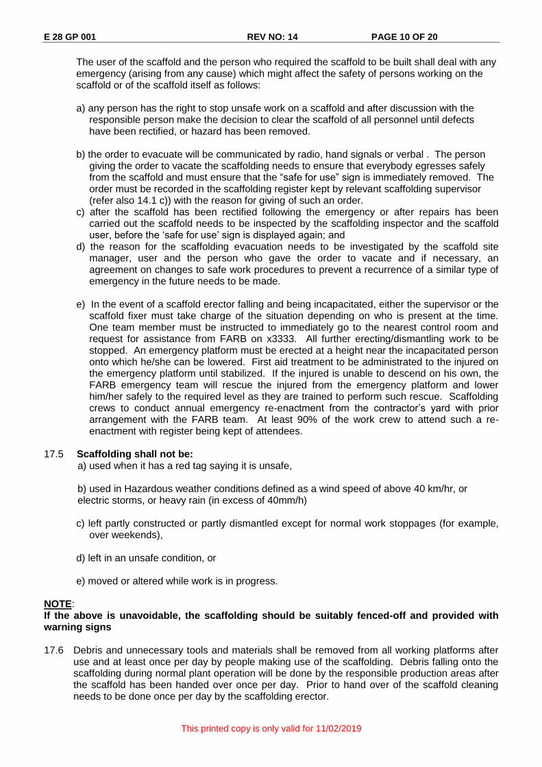
The user of the scaffold and the person who required the scaffold to be built shall deal with any emergency (arising from any cause) which might affect the safety of persons working on the scaffold or of the scaffold itself as follows:
a) any person has the right to stop unsafe work on a scaffold and after discussion with the
responsible person make the decision to clear the scaffold of all personnel until defects have been rectified, or hazard has been removed.
b) the order to evacuate will be communicated by radio, hand signals or verbal . The person
giving the order to vacate the scaffolding needs to ensure that everybody egresses safely from the scaffold and must ensure that the “safe for use” sign is immediately removed. The order must be recorded in the scaffolding register kept by relevant scaffolding supervisor (refer also 14.1 c)) with the reason for giving of such an order.
c) after the scaffold has been rectified following the emergency or after repairs has been carried out the scaffold needs to be inspected by the scaffolding inspector and the scaffold user, before the ‘safe for use’ sign is displayed again; and
d) the reason for the scaffolding evacuation needs to be investigated by the scaffold site manager, user and the person who gave the order to vacate and if necessary, an agreement on changes to safe work procedures to prevent a recurrence of a similar type of emergency in the future needs to be made.
e) In the event of a scaffold erector falling and being incapacitated, either the supervisor or the
scaffold fixer must take charge of the situation depending on who is present at the time. One team member must be instructed to immediately go to the nearest control room and request for assistance from FARB on x3333. All further erecting/dismantling work to be stopped. An emergency platform must be erected at a height near the incapacitated person onto which he/she can be lowered. First aid treatment to be administrated to the injured on the emergency platform until stabilized. If the injured is unable to descend on his own, the FARB emergency team will rescue the injured from the emergency platform and lower him/her safely to the required level as they are trained to perform such rescue. Scaffolding crews to conduct annual emergency re-enactment from the contractor’s yard with prior arrangement with the FARB team. At least 90% of the work crew to attend such a re-enactment with register being kept of attendees.
17.5 Scaffolding shall not be: a) used when it has a red tag saying it is unsafe, b) used in Hazardous weather conditions defined as a wind speed of above 40 km/hr, or electric storms, or heavy rain (in excess of 40mm/h)
c) left partly constructed or partly dismantled except for normal work stoppages (for example, over weekends),
d) left in an unsafe condition, or e) moved or altered while work is in progress.
NOTE: If the above is unavoidable, the scaffolding should be suitably fenced-off and provided with warning signs
17.6 Debris and unnecessary tools and materials shall be removed from all working platforms after
use and at least once per day by people making use of the scaffolding. Debris falling onto the scaffolding during normal plant operation will be done by the responsible production areas after the scaffold has been handed over once per day. Prior to hand over of the scaffold cleaning needs to be done once per day by the scaffolding erector.

E 28 GP 001 REV NO: 14 PAGE 11 OF 20
This printed copy is only valid for 11/02/2019
17.7 Where deemed appropriate and by virtue of risk assessment, “Catch Nets” will be installed to prevent the falling of material / tools, equipment and the like. All work zones must be appropriately barricaded off beneath construction activities.
18. REFERENCES
18.1 RBM 2.9.2 Safety registers. 18.2 Regulation 8.8. of the Mine Health and Safety Act (Act 29 of 1996). 18.3 South African National Standard: SANS10085-1:2004 the design, erection, use and inspection
of access scaffolding. 18.4 Scaffolds - typical configurations: RBM Drg. No. 0999-S-0054-REV-1. 18.5 Cat ladder details: RBM DRG. No. 0999-S-0052-0053. 18.6 Register: Ladders/Scaffolds: G:\Proc\Safety\Forms\2.14/3. 18.7 Rio Tinto Safety Standards C4 (Working at height) 18.8 DME directive / letter (use, erection and inspection of access scaffolding
(IMN 93 / 07-06-1989). 18.9 Construction Regulations of the Occupational Health and Safety Act.(85 of 1993). (available
on Data 9000). 18.10 COP 28 – Working at heights. 18.11 E 28 GP 002 Safety Harnesses and fall arrest systems usage standards and responsibilities.
19. APPENDICES
Appendix 1 – System scaffolding recommendations Appendix 2 – Typical Format for Scaffold Inspection Register Appendix 3 -- Check list for inspection Appendix 4 – Standard scaffolding access towers – RBM drawing Appendix 5 – Letter of appointment as a competent person in Scaffolding Design Appendix 6 – Arrangement of Protective Shield
20. REVISION HISTORY
Rev no Description Page/s Date
0 New SOP All July 2004 1 Total revision.
Number of GP changed from E28 SOP 01. Title changed from Fall Prevention – Scaffolding standards.
All Sept 2009.
2 Point 3.3 (b) – added last phrase: before being dismantled. Point 3.5 Changes made to examples of scaffold design. Point No 4. (a) – added GM Final Products and GM Mining. (b) Added 2.9.2 appointments. Point No 5.2 changed definition of “Kwiklok” scaffold. Point 9.8 – Changed Heavy (320kg/m2) scaffold platform to be authorised by a certified Engineer. Point 9.10 – Distance of scaffold platforms from scaffolds changed. Point 9.17 – Last sentence added.
1, 2, 5, 6, 8, 15 & 16.
Nov 2009

E 28 GP 001 REV NO: 14 PAGE 12 OF 20
This printed copy is only valid for 11/02/2019
Rev no Description Page/s Date
Point 15.4 – point f added. Appendix 4 – Check list for inspection added.
3 Para 3, 3.3 c and d – colour of lanyards and attachment of restraining lanyard Para 7, point 7.5 added Included paragraphs 9 and 10. Removed annexure – Where registers are kept 16.2 – Scaffolding registers kept by Scaffolding Supervisor. 17.4 (a-d) Emergency procedure updated Change annexure to appendix and remove appendix 4 and becomes Appendix 3 Appendix 3 updated Appendix 4 included 14.2 Removed details of colour coding and replaced with ” The appointed Scaffolding contractors to supply RBM with their proposed Colour codes for the duration of their contract.”
2, 4, 5, 9, 10, 12,15
February 2010
4. Para 3, 3.3 e – use of 0.5 meter Lanyard. Para 5.4 – added. Para 8.1 – changed Para 8.1 a, 8.2 a, b, c and e added.- Special scaffolds. Para 8.3. - added. Para 9.4. - “ equivalent to” changed to “greater than”. Para 17.5 a) – added. Para 17.5 b) – added. Appendix 3 Check list for Scaffolding Modified to include changes as above.
2, 3, 4, 5, 9 & 14
August 2011.
5.
Para 8.1 – Last sentence Added refer to appendix 5 Added 8.4 Para 17.5 (b) last sentence Added heavy rain (in excess of 40mm/h) Para 19 – Appendices - Added Appendix 5
4,5, 9,10 & 17
Sept. 2011
6. Para 3.3 b. modified to read “An inspection of ALL exposed erected scaffolding (whether handed over or not) is carried out after periods of inclement weather such as heavy rains and strong wind, as defined in item 17.5. b) and the inspection must be recorded in the log for the scaffold. The Scaffold Log’s to be initiated on erection of the scaffold and terminated when the scaffold is dismantled both dates inclusive.”
1. Sept 2012.
7 Item 17.2 changed the figures in brackets at the end of the sentence from (see also 15.5) to (see also 17.5).
8 Item 16.3 changed figures in brackets at the end of the sentence from (see also 15.1) to (see also 17.1)
8 Nov 2012
9.
Item 14.1 changed the word “Material” to “Ladders”. Item 14.2 changed the number 12 to 24.
7 Feb 2013
10. Updated titles.

E 28 GP 001 REV NO: 14 PAGE 13 OF 20
This printed copy is only valid for 11/02/2019
Rev no Description Page/s Date
Item 7.4 changed reference from “SOP 29A (Manual Handling)” to “E29 GP 003 - Safe Manual Lifting Operations” Inserted 7.6 to 7.8 to include proper description of Protective Shields and barricading Added Appendix 6 - Arrangement of Protective Shield
4
18
March 2015
11. Pipe end caps compulsory on all scaffold bracing tubes and pipes exceeding 4m length
4 27 Nov 2015
12. Item 11.9 – 1st paragraph – removed sentence “except the side facing the structure” 2nd bullet – add in paragraph relating to toe boards “which includes all stepped platforms to prevent items falling off of any section of the working platform” Item 11.10 – changed wording and add last sentence “ The responsible plant engineer must give approval where it is necessary to remove the toe boards facing the structure. Item 17.1 – added: e) where trap-doors are used to access the platforms, all users must ensure that the trap-doors are always closed after using it
7,9 June 2016
13 Added 10.4 Where required by risk assessment a detailed plan must be provided for erection and dismantling with reference to appendix 4 and 6.
6 March 2017
14 Item 7.5 – Added last sentence : “When handling cross brasses, standards and all scaffold ‘fittings’ and connections they should be removed or securely tightened before erection and dismantling to prevent injury. EG Fixed couplings Swivel joints, swingover bolts, Tube clamps,. Clamps and brackets.
4 December 2018
APPROVAL
POSITION NAME DATE SIGNATURE
GM Technical & AM J Venter

E 28 GP 001 REV NO: 14 PAGE 14 OF 20
This printed copy is only valid for 11/02/2019
APPENDIX 1
SYSTEM SCAFFOLDING RECOMMENDATIONS
TABLE 1
TYING FREQUENCY OF INDEPENDENT SCAFFOLDING
Area of Scaffolding per tie, m2, max.
Type of Tie No Sheeting Sheeting
Tubular Unit Scaffolding Tubular Unit Scaffolding
Non-movable fixed tie 32 32 Movable fixed tie 32 26 Non-movable reveal tie 22 18 Movable reveal tie 18 15
2. For sheeted scaffolds, max. height 15m : For scaffolds over 15m high refer design office or competent engineer.
TABLE 2
TUBULAR STEEL UNIT (SYSTEM) SCAFFOLDING CLASSIFICATION OF SCAFFOLDING
Table based on 60m high scaffold with 6 numbers boarded lifts which includes working platforms as indicated in columns
1 2 3 4 5 6 Class Examples
of Usage
Number of Working Platform Levels
Platform Safe
Working Loading kg/m2
Spacing of Standards m,
max.
Platform Width
Number of Scaffold Boards
Min Max
Very Light (VL) Inspection Painting Stone Cleaning
6 x VL 80 2,5 3 5
Light (L)
Repointing Replacing Windows Plastering Insulation
4 x L 160 2,5 4 5
Medium (M) New Building Brick Work Block Work
2 x M 1 x VL
240 2,5 5 5
Heavy (H)
Masonry Heavy Cladding
Refer design office for recommendations
Note : Depending on the height of the scaffold (less than 60m high) the following factors could be varied : 1. Number of boarded platforms. 2. Number of working platforms.
E 28 GP 001 REV NO: 14 PAGE 15 OF 20
This printed copy is only valid for 11/02/2019
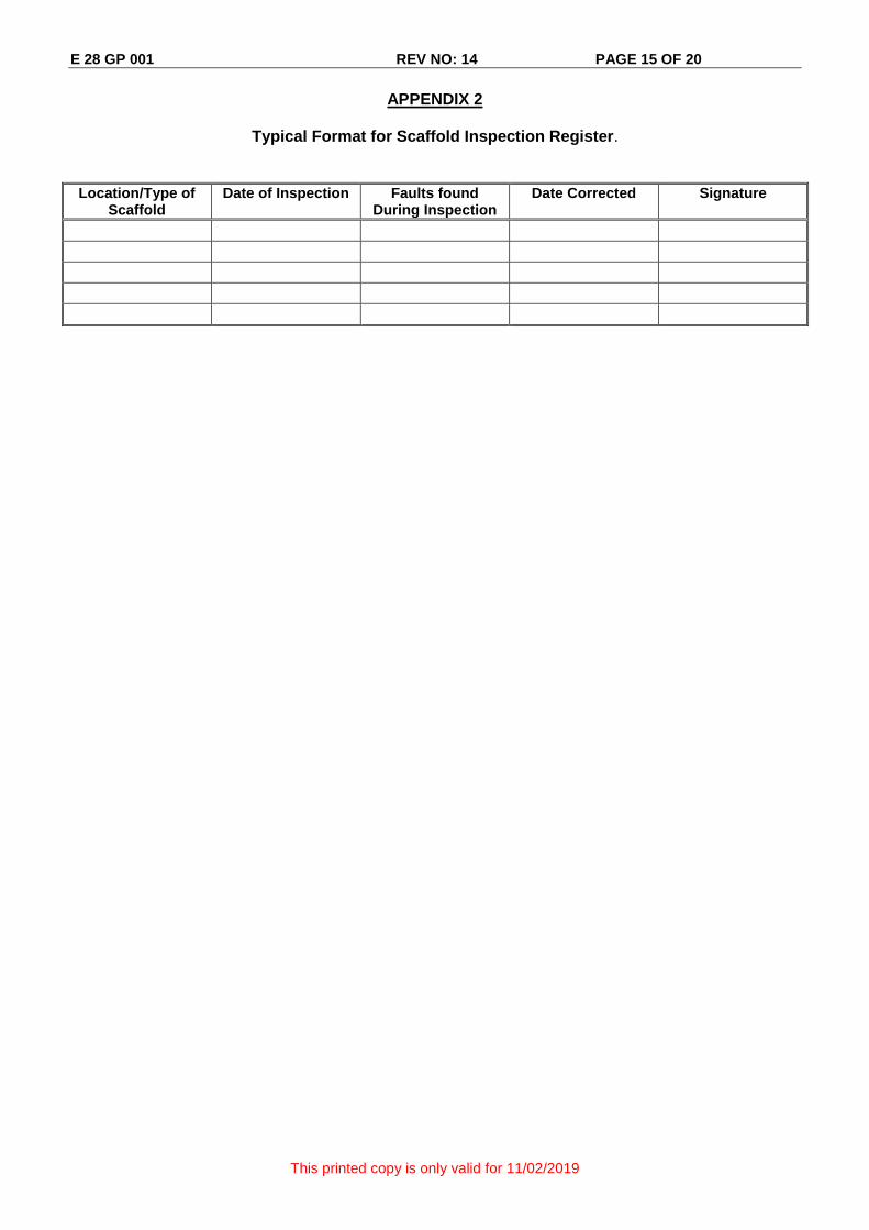
APPENDIX 2
Typical Format for Scaffold Inspection Register.
Location/Type of Scaffold
Date of Inspection Faults found During Inspection
Date Corrected Signature

E 28 GP 001 REV NO: 8 PAGE 16 OF 20
This printed copy is only valid for 11/02/2019
APPENDIX 3
CHECK-LIST FOR SCAFFOLDING INSPECTION:-
SANS 10085 and RBM E 28 GP 001
Yes
No
1 Equipment Ledgers Place Ledger every 1 x lift height. (Not to exceed 2 meters.)
Foot tie at base of sloped foundations if ledgers cannot be attached to all legs within 500mm of the base.
Standards “V” pressings to be aligned. (Upright members to preferably have staggered joints. SANS 10.12.2.1.
“The external upright members have joints fully connected by bolts, locking pins or Straps. SANS 10.12.2.7.)
2 Foundations Sole-boards Are they present (Not required on Concrete more than 75mm thick?)
Are they the right size for the application (At RBM we recommend Continuous under 2 Standards with 500mm overhang on both ends. SANS 8.4)
Are they supporting load correctly (when placed on grating must be supported by a jack underneath and where possible spread the load on to the Grating support steelwork. For soft/sandy soils two long sole boards side by side and continuous under at least two standards with 500mm overhang on both ends with a 450mm board across both where the standard is erected.)
Base Jacks Are they present and correct. Inspection done and deviations noted.
Are they the right Type (Swivel bases to be used on Sloping floors?)
Is the adjustment height correct (recommended Max of 300mm. Base plate to sit flat on the board no Gaps.) Base plate to be 150mm x 150mm. (Not smaller)
3 Height Restrictions See Sans 7.1 (Rule of thumb: - multiplying the minimum width by factor of 3.)
4 Ties Tied-in Towers Every 4m up, under top platforms and on both sides of working surface face. (Best Practice must be attached to the Standards).
Independent
Every 32m2 i.e. every 4m up on 1st leg and last leg , Bottom to Top and repeated every 7.5 to 8m – NB – only for non-sheeted scaffolds (sheeted below 15m in height = 26m2 – sheeted above 15m in height = Engineer’s approval). (Best Practice must be attached to the Standards).
770mm Tower and independent Ties for 770mm scaffold = 770mm x 3 = Every 2,3m up and then the same as above.
5 Buttress Tower and Independent Design Required. Used to increase the foot-print of the scaffold to comply with the height restriction i.e. not more than 4 x minimum base dimension.
6 Bracing Free-standing Towers
Braced as per SANS 10.12.2 where possible brace all 4 sides, attached to the Standards and within 300mm of the node point were the upright and horizontal members join. Continuous to under the top platform, additional ledgers to be erected to create node points if required. Minimum requirement 1 x Face brace and 1 x Transverse Brace.
Plan brace every 4m up and under top platform.
Mobile Plan brace at base for mobiles and braced on all 4 sides. (Plan Brace at base, every 4 meters and under top platform. Castors must have brakes and must not be able to drop out when wheel is not in contact with the ground)
Tied-in Towers Braced as per SANS 10.12.2 where possible brace 3 sides, attached to the Standards and within 300mm of the node point were the upright and horizontal members join. Working surface face can remain open to facilitate work efficiency.
Plan brace every 4m up and under top platform.
Independent Face bracing 1st and every 8th bay (or braced bays not to exceed 20m).
Transverse bracing every alternative leg (all odd numbered legs) as well as last leg if it is an even numbered leg.
E 28 GP 001 REV NO: 14 PAGE 17 OF 20
This printed copy is only valid for 11/02/2019
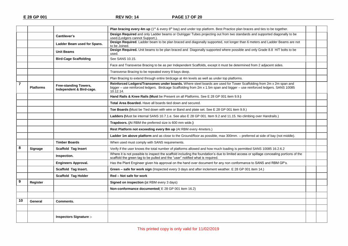
Plan bracing every 4m up (1st & every 8th bay) and under top platform. Best Practice plan braces and ties to be together.
Cantilever’s Design Required and only Ladder beams or Outrigger Tubes projecting out from two standards and supported diagonally to be used.(Ledgers cannot Support.).
Ladder Beam used for Spans. Design Required. Ladder beam to be plan braced and diagonally supported, not longer than 6 meters and Ladder Beams are not to be Joined.
Unit Beams Design Required. Unit beams to be plan braced and Diagonally supported where possible and only Grade 8.8 H/T bolts to be used.
Bird-Cage Scaffolding See SANS 10.15.
Face and Transverse Bracing to be as per Independent Scaffolds, except it must be determined from 2 adjacent sides.
Transverse Bracing to be repeated every 8 bays deep.
Plan Bracing to extend through entire birdcage at 4m levels as well as under top platforms.
7 Platforms
Free-standing Towers, Independent & Bird-cage.
Reinforced Ledgers/Transomes under boards. Where steel boards are used for Tower Scaffolding from 2m x 2m span and bigger – use reinforced ledgers. Birdcage Scaffolding from 2m x 1.5m span and bigger – use reinforced ledgers. SANS 10085 10.12.14.
Hand Rails & Knee Rails (Must be Present on all Platforms. See E 28 GP 001 item 9.9.)
Total Area Boarded. Have all boards tied down and secured.
Toe Boards (Must be Tied down with wire or Band and plate set. See E 28 GP 001 item 9.9.)
Ladders (Must be internal SANS 10.7.1.e. See also E 28 GP 001. Item 9.2 and 11.15. No climbing over Handrails.)
Trapdoors. (At RBM the preferred size is 600 mm wide.)
Rest Platform not exceeding every 8m up (At RBM every 4meters.)
Ladder 1m above platform and as close to the Ground/floor as possible, max 300mm. – preferred at side of bay (not middle).
Timber Boards When used must comply with SANS requirements.
8 Signage Scaffold Tag Insert Verify if the user knows the total number of platforms allowed and how much loading is permitted SANS 10085 16.2.6.2
Inspection. Where it is not possible to inspect the scaffold including the foundation’s due to limited access or spillage concealing portions of the scaffold the green tag to be pulled and the “user” notified what is required.
Engineers Approval. Has the Plant Engineer given his approval on the hand over document for any non conformance to SANS and RBM GP’s.
Scaffold Tag Insert. Green – safe for work sign (Inspected every 3 days and after inclement weather. E 28 GP 001 item 14.)
Scaffold Tag Holder Red – Not safe for work
9 Register Signed on inspection (at RBM every 3 days)
Non-conformance documented( E 28 GP 001 item 16.2)
10 General Comments.
Inspectors Signature :-
E 28 GP 001 REV NO: 8 PAGE 18 OF 20
This printed copy is only valid for 11/02/2019
APPENDIX 4
RBM Drawing 0999-S-00054 Standard Scaffolding Access Towers
Elevations.pdf
APPENDIX 5
Letter of appointment as a competent person in Scaffolding Design
(Letter available in RBM Templates)
2215_001.pdf

E 28 GP 001 REV NO: 14 PAGE 19 OF 20
This printed copy is only valid for 11/02/2019
APPENDIX 6
TYPICAL ARRANGEMENT OF PROTECTIVE SHIELD, TO BE IN PLACE WHEN:
ERECTING, DISMANTLING OR MODIFYING SCAFFOLDING

E 28 GP 001 REV NO: 14 PAGE 20 OF 20
This printed copy is only valid for 11/02/2019
Appendix 7 - Scaffold Tube Inserts