general specification and testing procedures for … publications/aaamsa/sigu.doc… · general...
TRANSCRIPT

General Specification and
Testing Procedures for
Sealed Insulated Glass Units (SIGU)
August 2012
Administered by
Page 2
PO Box 7861, Halfway House, 1685
ASSOCIATION OF ARCHITECTURAL ALUMINIUM MANUFACTURERS OF SOUTH AFRICA Trading as the AAAMSA Group Registration #: 1974/00006/08
Association Incorporated under Section 21
P O Box 7861 1st floor, Block 4 HALFWAY HOUSE Conference Park 1685 # 1 2nd Road
Midrand (011) 805-5002/3 Fax: (011) 805-5033 E-mail: [email protected] Web site: www.aaamsa.co.za Endorsed by:
DISCLAIMER Great care has been taken to ensure that the information provided here is correct. No responsibility will be accepted by AAAMSA for any errors and/or omissions which may have inadvertently occurred. All information, recommendation or advice contained in these AAAMSA General Specifications and Selection Guides is given in good faith, to the best of AAAMSA’s knowledge and based on procedures currently in effect. Because actual use of AAAMSA General Specifications and Selection Guides by the user is beyond the control of AAAMSA, such use is within the exclusive responsibility of the user. AAAMSA cannot be held responsible for any loss incurred through incorrect or faulty use of this General Specification and Selection Guide. This Guide may be reproduced in whole or in part, in any form or by any means, provided the reproduction or transmission acknowledges the origin and copyright date.
Copyright © AAAMSA 2012

Page 3
CONTENTS Page
1 Scope 4
2 Normative references 4
3 Definitions 5
4 Materials 5
5 Dimensions 5
6 Dimensional tolerances 5
7 Marking descriptions 6
8 Performance 6
Annexures A – Testing Procedures 7
Page 4
1. SCOPE
This specification specifies performance requirements and associated test methods for the sealing arrangements and fabrication of factory made sealed insulating glass units. The type of glass and the maximum dimensional tolerances for such units are also specified. The detailed design of units is not specified. In addition, attention is drawn to the fact that no requirements are included concerning the applications for which double glazing units, complying with the requirements of the standard, may be suitable. For guidance on the correct choice of glazing for a particular application, for instance where wind loading requirements need to be considered, SABS 10137 should be consulted. The thermal and acoustic properties of units are not specified in this specification, but typical thermal transmittances for sealed insulated glass units under varying conditions of exposure are given in Table 6 of SANS 204. Note: This specification does not apply to units incorporating a plastics-covered annealed glass.
2. NORMATIVE REFERENCES
The following standards contain provisions which, through reference in this text, constitute provisions of this standard. All standards are subject to revision and, since any reference to a standard is deemed to be a reference to the latest edition of that standard, parties to agreements based on this standard are encouraged to take steps to ensure the most recent editions of the standards indicated below are applied. Information on currently valid national and international standards may be obtained from the South African Bureau of Standards www.sabs.co.za CSN EN 1279-3: Glass in building – Insulating glass units – Part 3: Long term test method and requirements for gas leakage rate and for gas concentration tolerances. CSN EN 1279-4: Glass in building – Insulating glass units – Part 4: Method of test for the physical attributes of edge seals. SANS 10400: The applications of the National Building Regulations SANS 10137: The installation of glazing in buildings SANS 1263-1: Safety and Security glazing materials for buildings – Human Impact SANS 1263-2: Safety and Security glazing materials for buildings – Burglar/Vandal resistance SANS 1263-3: Safety and Security glazing materials for buildings – Bullet resistance SANS 17: Glass & Plastics in Furniture SANS 204: Energy Efficiency in Buildings SANS 680: Glazing putty for wooden and metal window frames SANS 1817: Work on glass SANS 50572-1: Glazing in Building – Definitions SANS 50572-2: Glazing in Building – Float Glass SANS 50572-3: Glazing in Building – Polished wire glass SANS 50572-4: Glazing in Building – Drawn sheet glass SANS 50572-5: Glazing in Building – Pattered glass SANS 10400: The application of the National Building Regulations
Part A: General principles and requirements Part B: Structural Design Part N: Glazing Part T: Fire Protection Part XA: Energy usage in buildings
SANS 613: Fenestration products – Mechanical performance criteria SANS 549: Shower Enclosures for domestic purposes SANS 1545: Safety rules for the construction and installation of lifts
Page 5
3. DEFINITIONS For the purpose of this specification the following definitions apply.
3.1 sealed insulated glass units (SIGU). Assemblies consisting of two or more panes of glass fixed at a given distance apart by a spacer and sealed around the edges.
Note: The space thus formed will contain dehydrated air or other gasses. 3.2 symmetrically sealed insulating glass unit. A unit comprising two panes of glass of the same type
and thickness. 3.3 asymmetrically sealed insulating glass unit. A unit comprising two panes of dissimilar glass and/or
differing thickness. 3.4 spacer. The component used to control the space between the panes of glass in double glazing units. 3.5 fracture. A crack in a glass component which penetrates through the thickness of the glass. 3.6 nominal thickness. The manufactured thickness within agreed tolerances. 3.7 nominal thickness of the unit. The sum of the nominal thicknesses of the two panes of glass and the
spacer. 3.8 Glas – Filling. An inert gas introduced into the SIGU air gap to improve thermal and/or acoustic
insulation properties. 4. MATERIALS
All glass used in the fabrication of sealed insulating glass units shall be flat glass and shall be of one of the types classified in BS 952. If the unit includes edge protection in the form of a channel or tape as a permanent component, this shall be of corrosion resistant material, e.g. aluminium alloy 60635T5 complying with the requirements of BS 1474 or stainless steel 316S15 complying with the requirements of BS 970:Part 4 that has a chromium content of not less than 14%. Note: It is intended that glass in these units should be fixed in accordance with the recommendations of
SANS 10137. The material of the spacer shall be such that the unit will comply with the performance of this specification.
5. DIMENSIONS
For overall size limitations refer to manufacturer’s recommendation. Glass and spacer combinations must be designed such that atmospheric pressure fluctuations and differentiations will not result in the glass plies touching.
6. DIMENSIONSAL TOLERANCES 6.1 THICKNESS The thickness of the unit shall be measured on the glass, as close to the edge as is possible, and shall
be the thickness of the two panes of glass plus the air space. The thickness of the unit shall not vary from the nominal thickness of the unit by more than the following tolerances:
(a) For two panes of glass each of 6mm or less plus air space +0 -2mm (b) For two panes of glass each of over 6mm plus air space +0 –2mm
The thickness, when calculated as given in 6.1(a) and (b) in any one unit, shall not vary by more than
1.0mm around the perimeter of the units.
6.2 LENGTH AND WIDTH For tolerances on length and width of units refer to manufacturers recommendations.

Page 6
7. MARKING DESCRIPTION
1. Markings in terms of SANS 10400-N for safety glazing materials to appear on both inner and outer panes. In the event that SIGU’s are glazed in safety glazing areas both lites of the unit must comply with the requirements of SANS 1263 Part 1 and both lites must be marked in such a manner that marking is visible after installation.
2. The unit shall be indelibly marked with the name or trade name of the unit assembler/manufacturer, visible after glazing, so as to provide full traceability. This may include, but not limited to, marking of spacer.
8. PERFORMANCE REQUIREMENTS Sealed insulating glass units shall comply with the following performance requirements:
(a) There shall be no evidence of contamination on the interior glass surfaces of the units when inspected in accordance with A.2.1;
(b) The units shall show no indication of leakage at the seal when tested in accordance with A.2.2;
(c) The units shall show no evidence of frost or condensation on the interior glass surfaces when tested in accordance with A.2.3;
(d) The units shall show no evidence of fogging or contamination on the interior glass surfaces after being
tested by ultraviolet exposure in accordance with A.2.4;
(e) A minimum of 11 of the 12 units tested in accordance with A.2.5 and A.2.6 shall show no evidence of condensation or frost on the interior glass surfaces.
(f) In the event SIGUs are marketed as gas-filled, the amount of gas in the cavity must be a minimum of
85% by volume. The gas-filling requirements must comply with CSN EN 1279 Part 3 and Part 4. To verify compliance, test specimen units shall be prepared and tested in accordance with Appendix A. If the
test specimen units pass the tests as described in Appendix A, the units which they represent shall be deemed to comply with the performance requirements specified in (a) to (f) above.
Page 7
ANNEXURE A
METHOD OF TEST A.1 PREPARATION OF TEST SPECIMENS Prepare a set of 10 specimen units of 4mm clear float glass with an overall glass size of 360mm x 510mm +3 - 0mm and with a nominal air space of 12mm. Remove temporary edge channels or other means of protection for handling before any of the units are tested. Ensure that the specimens are fully representative in design and construction of the manufacturer’s production units and that every unit is legibly marked for identification during the tests. A.2 TEST PROCEDURES A.2.1 General visual examination of 10 specimen units described in A.1. Clean the specimen units and mount each in turn in a viewing box (see figure 1). With the lamps switched on, position the viewing box so that the specimen unit is at eye level. Note: Examination may be carried out in a dark room, if necessary, to eliminate any reflection on the glass. Stand
directly in front of, and at a distance of 2m from, the viewing box and look for evidence of dirt or other contamination on the interior glass surface. Check that any dirt or other contamination found is on the interior glass surfaces of the unit by viewing again after cleaning the exterior glass surfaces with alcohol or the equivalent¹. If there is any contamination on the interior glass surfaces the specimen shall fail the test.
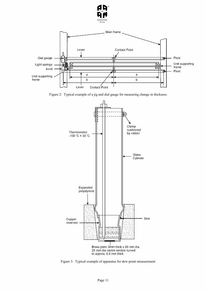
A.2.2 Initial seal test of 10 specimen units described in A.1. A.2.2.1 Test the 10 units in batches using a vacuum chamber. Mount each unit in a jig fitted with a dial gauge² that will measure any change in thickness at the centre of the unit (see figure B1). Place the jigs holding the units in the vacuum chamber in batches, in such a way that the dial gauges are visible from outside the chamber and can be accurately read. A.2.2.2 The sensitivity of each dial guage² shall be such that any change in thickness be measured to 30um. A.2.2.3 Precondition each unit to be tested to a temperature equal to the temperature inside the vacuum chamber, which should be 23±2°C, and maintain that temperature for a minimum period of 12h before the test commences. A.2.2.4 Before commencing the tests, either set the dial gauge² at zero or record the thickness registered on the dial gauge². A.2.2.5 After the batch of specimens is in position, lower the pressure in the vacuum chamber 100±5mbar³ below the atmospheric pressure and between 5min and 10min of the low pressure being reached. Read the dial gauge and record the thicknesses. A.2.2.6 Maintain the pressure chamber at the low pressure for 2,5h, after which read the dial gauge² again within a period of 5min. and record the thicknesses. A.2.2.7 Evaluated the deflection for indication of leakage as follows: (a) Initial deflection. All units shall have an initial deflection showing an increase in thickness of at least
0,8mm (b) Deflection after 2,5h. No unit shall have a possible reduction in deflection after 2,5h which exceeds 15%
of its initial deflection. A.2.2.8 Breakage of the glass of any of the 10 specimen units tested shall not constitute a failure. If any units do fracture they may be replaced and the test repeated on these before continuing the remaining tests. A.2.3 Initial dew-point temperature test of 10 specimen units described in A.1. A.2.3.1 Precondition the set of 10 specimen units to a temperature of 23±2°C and relatively humidity between 30% and 75% continuously for a period of one week before testing. A.2.3.2 Ensure that the upper limit of the initial dew-point is checked at a room temperature of 23±2°C using the apparatus illustrated in figure 3 (or similar apparatus).
Page 8
Fill the reservoir to a depth of 25mm with alcohol or the equivalent¹ and cool it to a temperature of -40°C, e.g. by the introduction of solid carbon dioxide, and maintain it at -40°C for the period of testing.
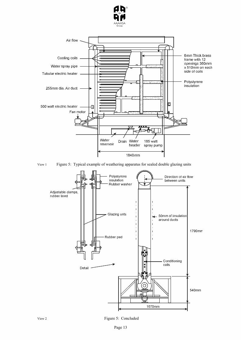
A.2.3.3 Apply a film of alcohol or the equivalent¹ to one face of each specimen unit. Holding the specimen unit in a horizontal position, with the prepared face uppermost, bring the apparatus (see figure 3) in contact with the prepared face and leave it in position for 3min. A.2.3.4 Remove the apparatus (see figure 3) from the upper surface, leaving the specimen unit in the horizontal position. Immediately, place a light beneath the unit and observe if any condensation or frost has formed on the interior glass surfaces. If any condensation or frost is present the specimen shall fail the test. A.2.4 Fogging test by ultraviolet exposure of two of the 10 specimen units described in A.1 A.2.4.1 Mount two specimen units in an ultraviolet test box (see figure 4) with an ultraviolet output of a minimum of 40 W/m², as measured with a distance of 300mm between the measuring source and the outside of the lamp glass⁴. Check the ultraviolet output prior to each exposure test. Maintain the air temperature within the test box at 50 ± 3°C, e.g. by adjusting the clearance between the top of the box and the lid. The ambient air temperature surrounding the test box shall be 23±2°C. A.2.4.2 Place the 150mm diameter cooling plates (see figure 4) centrally against the surface for identification. Then cool the plates by a continuous through flow of water and maintain the water temperature at the inlet at 16±2°C. The difference in temperature of the flow of water at the inlet and outlet points of the cooling plates shall not exceed 2°C. A.2.4.3 Expose the specimen units continuously, when positioned in the test box (see A.2.4.1 and A.2.4.2), to ultraviolet light for 168h using a Philips MLU300 or equivalent watt ultraviolet lamp (see figure 4) with the applied voltage maintained at 220±5V. At completion of the 168h period, remove the specimen units and store them at a temperature of 23±2°C for seven days. At the end of this time clean the exterior using powdered pumice to remove all scum and marks. A.2.4.4 View the specimen units in accordance with A.2.1, in such a way that the units are viewed through the marked surface (see A.2.3.2). Look for evidence of fogging or any oil or other contamination on the interior glass surfaces. If there is any contamination of the interior glass surfaces the specimen shall fail the test. A.2.4.5 If one or both specimens fail to pass the test, test two further specimen units and both shall then have to pass the test. Failure to do so shall invalidate further testing and the product shall be deemed to have failed. Breakage of glass under these tests shall not constitute failure; such units may be replaced by similar units from the 10 specimen units and the test repeated. However, in the event of failure in tests A.2.1, A.2.2, A.2.3 or A.2.4 no further tests shall be carried out and the product shall be deemed to have failed. A.2.5 Weather cycling test of four of the 10 specimen units described in A.1 and not tested in accordance with A.2.4 A.2.5.1 Place four specimen units in a laboratory weathering apparatus (see figure 5) so that the edges are not protected and one surface of each specimen unit is exposed to normal laboratory air at a temperature of 23±2°C and the other surface is exposed to the weathering cycle conditions. Take care that no stress is induced in the units by the method of fastening. The weather conditions shall consist of 320 consecutive cycles, during which there shall be continuous forced circulation of air through the apparatus and over the surface of the units, as follows: (a) Heating phase, lasting for 90±1min. At the beginning of this phase, raise the temperature to 52±3°C for the
remainder (if any) of this phase. (b) Natural cooling phase, lasting for 90±1min. Within this phase, 25±1min. after its commencement, spray
water over the surface of the units at a temperature of 24±3°C for 5±1min. (c) Forced cooling phase, lasting for 90±1min. At the beginning of this phase lower the temperature to -15±3°C
within 30min. and maintain it at -15±3°C for the remainder (if any) of the phase.
A.2.5.2 After 50 cycles inspect the units. Replace up to two units, which have suffered fractures in the body of the glass and continue to test. After a further 50 cycles again inspect any replaced units for fractures in the body of the glass and if one replaced unit has fractured replace it. Any further fracture constitutes a failure of that specimen unit.

Page 9
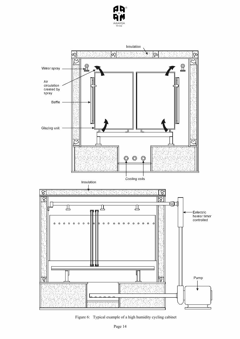
A.2.5.2 On completion of the 320 cycles (less for replaced units) remove the units from the apparatus, condition them continuously for one week at a temperature 23±2°C and r.h. between 30% and 75% and then check their dew-point temperatures by the method described in A.2.3.2 to A.2.3.4. If any contamination or frost is present the specimen unit shall have failed the test. A.2.6 High humidity cycling test of eight of the specimens described in A.1, which have not been tested in accordance with A.2.4 or A.2.5 A.2.6.1 Place the eight specimen units in a humidity cabinet (see figure 6) and expose them to humid air flow of not less than 95% r.h. Spray the water continuously between the cabinet walls and a baffle and allow the temperature to cycle within a range of 25±3°C to 55±3°C as follows: (a) Heating phase, lasting for 140±1min. At the beginning of this phase, raise the temperature in the
cabinet to 55±3°C within 90±10min. and maintain it at 55±3°C for the remainder of this phase. (b) Forced cooling phase, lasting for 40±1min. At the beginning of this phase lower the temperature in the
cabinet to 25±3°C during 30±10min. and maintain it at 25±3°C for the remainder (if any) of the phase.
Note: The rates of heating and cooling are markedly affected by the number of specimen units in the cabinet.
A.2.6.2 After 50 cycles inspect the units. Replace up to two units that have suffered fractures in the body of the glass and continue the test. After a further 50 cycles again inspect any replaced units for fractures in the body of the glass and if one replaced unit has been fractured, replace it. Any further fracture constitutes a failure of that specimen unit. A.2.6.3 On Completion of 224 cycles (less for replaced units), remove the units from the apparatus, condition them continuously for one week at a temperature of 23±2°C and r.h. between 30% and 75% and then check their dew-point temperatures by the methods described in A.2.3.2 to A.2.3.4. The presence of condensation or frost denotes a failure of the specimen unit. ¹ Remains liquid at -40°C ² Or other measuring devices with similar sensitivity. ³ 1 mbar = 10² N/m² = 0,1 kPa � The UVP International Inc.J-221 Blak Ray Long Wave Ultraviolet Meter is suitable for this purpose

Page 10
Figure 1: Typical example of a viewing box for ultraviolet exposure test
Page 11
Figure 2: Typical example of a jig and dial gauge for measuring change in thickness
Figure 3: Typical example of apparatus for dew-point measurement

Page 12
Figure 4: Typical example of ultraviolet fogging test apparatus
Page 13
View 1 Figure 5: Typical example of weathering apparatus for sealed double glazing units
View 2 Figure 5: Concluded
Page 14
Figure 6: Typical example of a high humidity cycling cabinet