generalized direction changing fall control of humanoid ... · control as a minimization problem,...
TRANSCRIPT

Generalized Direction Changing Fall Control of Humanoid Robots
Among Multiple Objects
Umashankar Nagarajan and Ambarish Goswami
Abstract— Humanoid robots are expected to share humanenvironments in the future and it is important to ensure safetyof their operation. A serious threat to safety is the fall of ahumanoid robot, which can seriously damage both the robotand objects in its surrounding. This paper proposes a strategyfor planning and control of fall. The controller’s objective isto prevent the robot from hitting surrounding objects during afall by modifying its default fall direction.
We have earlier presented such a direction-changing fallcontroller in [1]. However, the controller was applicable onlywhen the robot’s surrounding contained a single object. In thispaper we introduce a generalized approach to humanoid fall-direction control among multiple objects. This new frameworkalgorithmically establishes a desired fall direction throughassigned scores, considers a number of control options, andselects and executes the best strategy. The fall planner is alsoable to select “No Action” as the best strategy, if appropriate.The controller is interactive and is applicable for fall occurringduring upright standing or walking. The fall performance iscontinuously tracked and can be improved in real-time. Theplanning and control algorithms are demonstrated in simulationon an ASIMO-like humanoid robot.
I. MOTIVATION
Although the loss of balance and fall are rare for a
humanoid robot in typical controlled environments, it will be
inevitable in physically interactive environments. The result
of a fall can be severe both to the robot and to objects and
people in the vicinity.
One can ignore the possibility of a fall and wishfully
hope that its effects will not be serious. However, failure
studies, such as in car crash, have taught us against behaving
according to this instinct. In fact, planning and simulation
of failure situations can have enormous benefits, including
system design improvements, and support for user safety and
confidence. Following this philosophy we closely focus our
attention to the phenomenon of humanoid fall and attempt
to develop a comprehensive control strategy to deal with this
undesired and traumatic “failure” event.
Time is a premium during the occurrence of a fall; a single
rigid body model of the Honda ASIMO robot indicates that
a fall from the vertical upright stationary configuration due
to a mild push takes about 800-900ms. In some situations
the time to fall can be even shorter, and there is no opportu-
nity for elaborate planning or time-consuming control. Yet,
simulation and experimental results indicate that meaningful
This work was supported by Honda Research Institute USAU. Nagarajan is with The Robotics Institute, Carnegie Mellon University,
Pittsburgh, PA 15213, USA [email protected]. Goswami is with Honda Research Institute, Mountain View, CA
94041, USA [email protected]
modification to the default fall behavior can be imparted to
minimize damage to the robot or to the environment.
A humanoid fall controller may have two primary, and
distinctly different, goals: a) self-damage minimization and
b) minimization of damage to others. When fall occurs in an
open space, a self-damage minimization strategy can reduce
the harmful effects of the ground impact. If, however, the
falling robot can damage nearby objects or injure persons, the
primary objective is to prevent this from happening. This we
try to achieve by means of changing the default fall direction
of the robot such that even during falling it makes no contact
with the surrounding objects.
The first reported work on humanoid fall direction change
was in [1] and in the current paper we present a thorough
generalization, extension and improvement of this approach.
A sample of our current results is shown in Fig. 1. When
pushed with a large force, the humanoid robot falls on an
object when no controller is active, Fig. 1(a). When the
proposed fall controller is turned on, the robot successfully
avoids falling on the objects, Fig. 1(b).
The fall direction change controller exploits the fact that
regardless of its complex motion, a falling humanoid can
topple only about an edge or a vertex of its support base.
We appropriately change the robot’s support base geometry
to modify the position and orientation of this leading tipping
edge. This profoundly influences the robot’s fall behavior
as it is guided away towards a free area. The support base
geometry is modified through the lifting of a foot or a
stepping action, and the specific parameters for these actions
are selected using a brute-force process. Additional improve-
ments are achieved using inertia shaping [2] techniques.
(a) (b)
Fig. 1. A forward force of 230N applied to the robot. With no control,the robot falls on an object, (a), and successfully avoids the objects whenfall controller is turned on, (b). The black-outlined conical regions on theground represent the safe fall regions. The blue lines on the ground representthe scores for each foot placement strategy evaluated and the red line givesthe desired fall direction. The center of mass (CoM) trajectory during fallis shown in gray.

There are several major improvements compared to our
earlier work, as follows:
a) Multiple Objects: During a fall among multiple
objects, the robot must try to avoid falling in several di-
rections. In this paper, we newly formulate the fall direction
control as a minimization problem, wherein the robot tries to
minimize its deviation from a desired fall direction. The robot
algorithmically determines the desired fall direction from the
location of obstacles and the impending fall direction. With
only one object the robot had only one fall direction to avoid,
attempting to fall as far as possible from this direction (a
maximization problem). See Sec. IV-A.
b) Control Trigger: As described in [1] the Fall Trigger
Boundary (FTB) of a robot encloses a region in the robot’s
state space in which a given balance controller is able to
stabilize the robot. An exit through the FTB is an indication
of a certain fall and this event was used to activate a switch
from the robot’s balance controller to a fall controller. In our
current work, the fall trigger, which is the earliest prediction
of a fall, is distinguished from the control trigger, when
the control is launched. The controller must wait till the
control trigger because fall trigger may occur too early for the
robot to possess sufficient information to make an intelligent
decision. See Sec. III-D.
c) Simultaneous Foot Placement and Inertia Shaping:
The inertia shaping technique [2] to control the overall
composite rigid body (CRB) inertia [3] of the robot cannot
be launched before foot placement is completed, because
the two actions may be in conflict. Therefore, we introduce
partial inertia shaping, which is a procedure to change
the CRB inertia of the robot simultaneously during foot
placement, without using the joints involved in the latter.
See Sec. IV-B.
d) Inertia Shaping about CoP: The inertia shaping
procedure is used to change the CRB inertia of the robot.
In this paper we perform inertia shaping at the center of
pressure (CoP) and not at the CoM, for reasons discussed in
Sec. IV-B.
II. RELATED WORK
A number of recent papers reported on the damage min-
imization aspect of humanoid fall. In their exhaustive work
Fujiwara et al. ([4], [5], [6], [7], [8]) proposed martial arts
type motion for damage reduction, computed optimal falling
motions using minimum impact and angular momentum, and
fabricated special hardware for fall damage study. Ogata et
al. proposed [9], [10] two fall detection methods based on ab-
normality detection and predicted ZMP. The robot improves
fall detection through exponential learning or through on-
line CoM trajectory calculation. Renner and Behnke[11] use
model-based approach to detect external forces on the robot
and Daniel Karssen and Wisse[12] use principal component
analysis to detect fall. Following human movement based
search procedure Ruiz-del-Solar et al. implemented a low
damage fall sequence for soccer robots[13]. In [14], [15]
fall detection and control are treated together using Gaussian
mixture models and Hidden Markov model. Ishida et al.
employed servo loop gain shift to reduce shock due to
fall[16]. Fall damage minimization is obviously of natural
interest in biomechanics[17].
III. KEY CONCEPTS
This section will describe some of the key concepts used
throughout the paper.
A. Geometric Setup
In 3-D, both the robot and the surrounding objects are
approximated by circumscribing vertical cylinders centered
at their respective CoMs. On the horizontal projection, the
objects are represented by circles and the robot is represented
by a circle with its center at the CoM and the maximum
leg spread as its diameter (Fig. 2(a)). We assume that the
position and size of the objects are known to the robot at all
times. Following the configuration space formulation used
in traditional motion planning algorithms [18], the object
circles are grown by the radius of the robot circle and the
robot is reduced to a point (Fig. 2(b)). The entire planning
process uses information in polar coordinates (r,θ ) with the
point robot at the origin (0,0), where r ∈ R+ represents the
distance from the point robot and θ ∈ Θ = [0,2π] represents
the direction. The direction θ = 0 represents the reference
direction with respect to which all objects’ positions and
orientations are known. Only objects within a radius of 1.5
times the height of the robot are considered for the planning
process and the other objects are considered too far from the
robot to be hit.
0.5
1
1.5
2
30
210
60
240
90
270
120
300
150
330
180 0
ObjectRobot
(a)
30
210
60
240
90
270
120
300
150
330
180 0
Safe Fall
Regions
(b)
Fig. 2. The 2-D projection. (a) The yellow circle represents the robot.Its center is located at the robot’s CoM and its diameter is equal torobot’s maximum leg spread. The object circles shown in green are thecircumscribing circles of the objects’ 2-D projections. (b) The object circlesare grown by robot’s radius and the robot reduces to a point. Safe fall regions(cyan shaded cones) are the free cones in which the robot can fall withouthitting an object.
B. Fall Direction
In this paper, fall direction is defined as the vector con-
necting the robot’s initial and final CoM ground projections.
The initial state is at control trigger and the final state is the
ground robot touchdown, estimated using inverted pendulum
simulations. At fall trigger, all controllers on the robot are as-
sumed to be stopped and the joints are locked with the robot
behaving like a rigid body until control trigger is reached.

After control trigger is hit, the only active controller is the
safe fall controller that is described in Sec. IV-B. The fall
direction is independent of the intermediate configurations
of the robot, which implies that it is independent of the
CoM positions during fall. In the geometric setup described
in Sec. III-A, the fall direction is given by an angle θ f ∈ Θ.
C. Safe Fall Regions
A safe fall region, characterized by an object-free cone,
is the set of continuous fall directions (θ f ) with no objects
inside them as depicted by cyan cones in Fig. 2(b). These
represent the set of directions in which the robot can fall
without hitting an object. The number of safe fall regions,
ns f , is given by:
ns f = nob j −nint (1)
where, nob j is the number of non-intersecting objects and nint
is the number of pairs of intersecting expanded objects. The
set of all safe fall regions is given by SF = {SF1, ...,SFns f},
where SFj represents the jth safe fall region (free cone).
D. Fall Trigger Vs Control Trigger
The planning and strategy evaluation procedure discussed
in [1] was done at the occurrence of fall trigger. Fall trigger is
set off by a fall predictor and represents the earliest warning
of an impending fall. Although the fall predictor may predict
the imminence of a fall very early, we might not, at that point,
have sufficient information to select the best controller.
For example, the fall controller assumes that the estimation
of fall direction is accurate. This assumption holds only for
a steady fall, where the initial and terminal fall directions
coincide. For other cases, where the fall direction evolves
with time, this assumption may not hold. Therefore, in
order to make the best controller selection and launch the
controller, we must first ensure that the robot’s tipping
motion is steady. Control trigger is the instant, simultaneous
or subsequent to the fall trigger, when the robot’s tipping
motion is ascertained to be steady.
We have used the Capture Point[19] trajectory to evaluate
the steadiness of the tipping motion. The capture point is a
point on the ground to which the biped, when subjected to a
perturbation, can step to and stop without requiring another
step. Capture point is estimated using a linear inverted
pendulum model and is directly proportional to the velocity
of CoM. During steady fall, the capture point trajectory is
approximately a straight line (Fig. 3(a)). But, when there is a
spinning motion about an axis normal to the ground, the fall
is no longer steady and the capture point trajectory changes
direction as shown in Fig. 3(b).
It is generally true that the longer we wait following
the fall trigger, the better is our estimate of all quantities
pertaining to the fall. Although a moment before the robot
touches the ground, we can predict the fall direction with
100% accuracy, there is no time to do anything useful. So,
there is a trade-off between information and time.
At every instant we evaluate the steadiness of a fall by
computing the collinearity of a set of past capture points
X Linear Position (m)
YLin
ear
Pos
itio
n(m
)
0 0.1 0.2 0.3 0.4-0.2
-0.1
0
0.1
0.2
(a)
X Linear Position (m)
YLin
ear
Pos
itio
n(m
)
0 0.2 0.4 0.6 0.8-0.2
-0.1
0
0.1
0.2
(b)
Fig. 3. Capture point trajectories of a falling humanoid. Steady tippingresults in a straight line trajectory (a), and unsteady tipping motion resultsin a multi-segmented line (b). The straight line segments in (b) indicatesteady tipping about an edge even though the leading edge may change.
ending at the current time. If steadiness is not reached within
a time limit, the control trigger is automatically triggered
and the fall controller immediately launched. The number of
sequential capture points considered, the allowable limits of
collinearity and the time limit are all hand tuned for better
performance.
IV. SAFE DIRECTION CHANGING FALL
The fall direction change problem can be divided into two
phases: planning and control. The planning phase consists of
intelligent strategy selection and determination of a desired
safe fall direction. The robot’s current and predicted states
and the safe fall regions are taken into account during this
stage. The control phase consists of execution of the chosen
strategy. This section discusses these two phases in detail.
A. Planning
1) Scoring Fall Directions: Each fall direction θ fi receives
two scores (si1,s
i2), whose weighted sum gives the total score
si as shown below:
si1 =
1−∆θ f j
∆θ fmax, i f θ fi ∈ SFj
1, i f θ fi /∈ SF(2)
si2 =
2|θ fi−θ b
f j|
∆θ f j
, i f θ fi ∈ SFj
2|θ fi−θ b
f j∗|
∆θ f j∗, i f θ fi /∈ SF and θ fi → SFj∗
(3)
si = w1si1 +w2si
2, w1 +w2 = 1 (4)
where, ∆θ f jrepresents angle subtended by the jth safe fall
region SFj, θ bf j
represents the absolute angle of the bisector of
the jth safe fall region, ∆θ fmax represents the angle subtended
by the largest safe fall region and θ fi → SFj∗ means that the
jth safe fall region is the closest to θ fi . It is to be noted
that when θ fi ∈ SF , si1 ∈ [0,1],si
2 ∈ [0,1],si ∈ [0,1] and when
θ fi /∈ SF , si1 = 1,si
2 > 1,si > 1. i.e. the safe fall directions
receive a score less than or equal to one, whereas the unsafe
fall directions receive a score greater than one. The total
score si is zero when the fall direction θi is at the bisector of
the largest safe fall region. Therefore, lower the score, safer
is the fall direction.

2) Foot Placement Strategies: The planner evaluates and
selects from three foot placement strategies: a) No Action,
b)Lift a Leg and c)Take a Step.
a) No Action: There is no attempt at controlling the
robot beyond locking all joints and letting the robot fall down
as a rigid body. This strategy is adopted when the default fall
direction of the robot is already deemed safe.
b) Lift a Leg: This strategy is evaluated only when
the robot is in double-support phase. It involves two sub-
strategies, 1)lift left leg and 2)lift right leg. Lifting a leg
reduces the extent of support base to a single footprint. Al-
though apparently simple, this strategy can exert significant
influence on the toppling motion.
c) Take a Step: This strategy involves taking a step
from the robot’s current position. The number of possible
stepping locations provides a number of sub-strategies to be
evaluated. An inverted pendulum model is used to estimate
the amount of time available before the robot touches the
ground. This is used as the control duration for estimating
the allowable stepping region with leg Jacobians[1].
An appropriately taken step changes the support base
geometry the most and can exert a powerful nudge to the
robot’s fall direction. However, it also takes a relatively
long time to complete the step, and if the robot is already
undergoing tipping, there might not be enough time to
complete the step. There are cases where the swing foot
touches the ground before the step completion due to severe
inclination of the robot.
3) Inertia Shaping Strategies: Inertia shaping (Sec. IV-
B.2) strategies are sometimes used in conjunction with, and
at other times as a replacement for, the foot placement
strategies.
a) Whole Body Inertia Shaping: This strategy involves
employing inertia shaping techniques on the entire robot.
This technique recruits all the joints and replaces the foot
placement strategy when it fails to produce a safe fall.
b) Partial Inertia Shaping: This strategy involves us-
ing inertia shaping techniques only on those joints on the
humanoid that are not involved in the stepping.
4) Strategy Selection: The strategy selection is done in a
logical manner as presented in Fig. 4.
In case of steady fall, the fall direction estimation is more
accurate and the No Action and Lift a Leg strategies are given
preference over Take a Step strategies because the former are
guaranteed for a successful completion. In case of unsteady
fall or when the No Action and Lift a Leg strategies fail to
produce safe fall, all foot placement strategies are evaluated
and their estimated fall directions are assigned scores. The
strategy with the minimum total score is chosen to be the
optimal safe fall direction. As one can see, even when no
foot placement strategy produces a safe fall direction, the
algorithm chooses the strategy with the lowest score that
corresponds to the fall direction closest to the safe fall region.
When no foot placement strategy produces safe fall, partial
inertia shaping strategy is coupled with the optimal foot
placement strategy. The bisector of the safe fall region closest
to the direction corresponding to the optimal foot placement
Control Trigger
Best Strategy: A
Evaluate B
Select Minimum
Score Strategy
Best Strategy: B
Max
Wait Time
Exceeded?
No
Yes
NoSteady Fall?
Yes
Yes
No
Yes No
Yes
NoEvaluate C
Select Minimum
Score Strategy
Yes
No
Best Strategy:
Best of (A,B,C)
Best Strategy:
D + Best of (A,B,C)
Evaluate
A, B, C
Start Control
Implement Best Strategy
NoBest Strategy: E
Yes
Yes
No
Start Planning
Steady Fall?
Strategies:
A – No Action
B – Lift a Leg
C – Take a Step
D – Partial Body
Inertia Shaping
E – Whole Body
Inertia Shaping
Stop
Start
Fall Trigger?
Safe Fall?
Safe Fall?
Safe Fall?
Safe Fall?
Turn off Motors?
No
Yes
Evaluate A
T
R
I
G
G
E
R
W
A
I
T
P
L
A
N
N
I
N
G
C
O
N
T
R
O
L
Fig. 4. Decision making procedure for safe fall planning and control.
strategy is chosen to be the desired direction for the partial
inertia shaping procedure. This fall direction corresponds to
the local minima closest to the current fall direction. While
the optimal foot placement strategy tries to do the best it can,
partial inertia shaping tries to move the body to the closest
safe fall region.
The strategy selection procedure described above happens
only at control trigger. The strategy execution described in
Sec. IV-B happens after control trigger as shown in Fig. 4. At
any future time after execution of the chosen strategy, if the
robot’s fall direction is unsafe, whole body inertia shaping
is initiated. The bisector of the safe fall region closest to the
current fall direction is chosen to be the desired direction of
fall and the inertia shaping procedure tries to achieve it.
Finally, if the robot’s inclination angle exceeds a maximum

threshold, all the motors are turned off, i.e. all joints are
unlocked, in order to reduce damage due to impact.
B. Control
This section describes the implementation of stepping and
inertia shaping strategies.
1) Stepping Control: Given a desired stepping location,
we can achieve it by controlling the leg joints through inverse
kinematics. However, precise stepping is not trivial in case
of a tipping robot. The robot behaves as an underactuated
system and based on its joint angles, the robot does not
know that it is tipping. The only way the robot would know
this is with the use of other sensors like a gyroscope. The
Honda ASIMO robot has a 3-axis gyroscope and 3-axis
accelerometer, which can provide the information needed to
compute the base frame’s tipping transformation. The base
frame is attached to the centroid of the trunk. The controller
uses Jacobians to control the stepping motion. The necessary
joint velocities θ to move the swing leg to the desired
location is given by:
θ = JLR
#(PR − PL) (5)
where, JLR
#is the pseudo-inverse of foot-to-foot Jacobian JL
R ,
PR and PL are the linear velocities of the right and left feet
respectively.
2) Inertia Shaping Control: If the foot placement strategy
fails to produce a safe fall, the robot can attempt to change
the fall direction using inertia shaping [2]. This technique
changes the fall direction by generating an angular momen-
tum in the desired direction of fall. In inertia shaping we
control the CRB inertia of the robot.
The inertia shaping control described here is used to move
the robot in a desired direction, whereas in [1] it was used to
move the robot away from the direction to be avoided. Details
of deriving the desired inertia matrix Id can be found in [1].
Here inertia shaping is performed about the CoP (IP) and
not about the CoM (IG) as in [1]. This makes sense beause
the desired angular velocity used to derive the desired inertia
is computed about the CoP frame and hence the inertia
shaping procedure should also be done about the same frame.
Moreover, partial inertia shaping is more effective about CoP.
This is because the arm configurations make more significant
contributions to the CRB inertia about CoP. So, the desired
inertia matrix Id derived here is about CoP i.e. IPd (Fig. 5).
To implement inertia shaping, we string out the 6 unique
elements of the CRB inertia matrix in the form of a vector:
I(3×3) → I(6×1). Next we obtain the CRB inertia Jacobian
JI which maps changes in the robot joint angles into cor-
responding changes in I, i.e., δ I = JI δθ . The desired joint
velocities to attain Id are given by:
θ = J#I (Id − I) (6)
where J#I is the pseudo-inverse of JI .
Eq. 6 is used for whole body inertia shaping. During
partial inertia shaping, we recruit only the upper body joints
� �
�
�� ��� ��
���
�
��
Fig. 5. Comparing inertia shaping about CoM (left) and CoP (right).Ellipsoids with solid and shaded outlines, in each case, denotes current anddesired inertia, respectively. Note that inertia shaping about the CoP allowsa movement of the CoM (G to G′), which the other does not.
for Take a Step and stance leg joints for Lift a Leg. The CRB
inertia Jacobian JI can be re-written as:
JI = [JPIS JFP] (7)
where, JPIS is the CRB inertia Jacobian corresponding to the
joints that are free from foot placement strategy execution,
whereas JFP is the CRB inertia Jacobian corresponding to
the joints involved in foot placement strategy execution.
The desired angular velocities to attain Id by partial inertia
shaping are given by:
θPIS = J#PIS (Id − I − JFP θFP) (8)
where J#PIS is the pseudo-inverse of JPIS and θFP is given by
the controller for the optimal foot placement strategy.
V. RESULTS
We simulated the fall control procedure on an ASIMO-
like humanoid using Webots[20]. The robot’s environment
is set up with four objects as shown in Fig. 1. The robot is
pushed at its trunk CoM with horizontal forces of different
magnitudes and directions and the performance of safe fall
controller for each case was analyzed. All forces are of
duration 100ms. Some of the results are presented here.
Fig. 1 shows the safe fall regions and the scores corre-
sponding to each evaluated foot placement strategy when
pushed with a forward force of 230 N. It also shows safe fall
as a result of choosing Take a Step strategy after identifying
that No Action and Lift a Leg do not result in a safe fall.
When the robot is pushed with a backward force of 210 N,
the default fall is safe. Our planning procedure successfully
detects steady fall and chooses No Action as the best strategy,
which results in a safe fall as shown in Fig. 6. Fig. 7 shows
the safe fall behavior as a result of choosing Lift a Leg
strategy after identifying a steady fall when pushed with a
forward force of 210 N.
Fig. 8 shows safe fall as a result of choosing Take a
Step and Partial Inertia Shaping. As expected we can see
significant arm motions in this case. Although the push force
is in the same direction as in Fig. 7, the robot falls in a
different direction due to high nonlinearity in the system.
Fig. 9 shows safe fall as a result of performing Whole Body
Inertia Shaping when all foot placement strategies fail to
produce safe fall and No Action strategy is the optimal foot
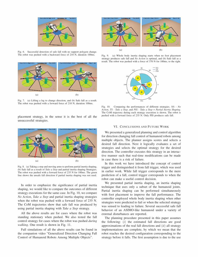
Fig. 6. Successful detection of safe fall with no support polygon change.The robot was pushed with a backward force of 210 N, duration 100ms.
(a) (b)
Fig. 7. (a) Lifting a leg to change direction, and (b) Safe fall as a result.The robot was pushed with a forward force of 210 N, duration 100ms.
placement strategy, in the sense it is the best of all the
unsuccessful strategies.
(a) (b)
Fig. 8. (a) Taking a step and moving arms to perform partial inertia shaping,(b) Safe fall as a result of Take a Step and partial inertia shaping Strategies.The robot was pushed with a forward force of 235 N for 100ms. The greenline shows the unsafe fall direction if partial inertia shaping was not used.
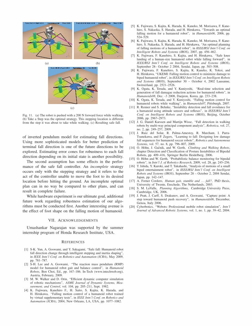
In order to emphasize the significance of partial inertia
shaping, we would like to compare the outcomes of different
strategy executions for the same case. In Fig. 10, we compare
No Action, Take a Step and partial inertia shaping strategies
when the robot was pushed with a forward force of 235 N.
The CoM trajectories show that safe fall was produced by
using partial inertia shaping with Take a Step strategy.
All the above results are for cases where the robot was
standing stationary when pushed. We also tested the fall
control strategy for cases where the robot was pushed during
walking. One result is shown in Fig. 11.
Full simulations of all the above results can be found in
the companion video ”Generalized Direction Changing Fall
Control of Humanoid Robots Among Multiple Objects”.
(a) (b)
Fig. 9. (a) Whole body inertia shaping starts when no foot placementstrategy produces safe fall and No Action is optimal, and (b) Safe fall as aresult. The robot was pushed with a force of 370 N for 100ms, to the right.
30
210
60
240
90
270
120
300
150
330
180 0
NATS
PIS
Fig. 10. Comparing the performances of different strategies. NA - No
Action, TS - Take a Step, and PIS - Take a Step + Partial Inertia Shaping.The CoM trajectory during each strategy execution is shown. The robot ispushed with a forward force of 235 N. Only PIS produces safe fall.
VI. CONCLUSIONS AND FUTURE WORK
We presented a generalized planning and control algorithm
for direction changing fall control of humanoid robots among
multiple objects. The planner assigns scores and selects a
desired fall direction. Next it logically evaluates a set of
strategies and selects the optimal strategy for the desired
direction. The controller executes this strategy in an interac-
tive manner such that real-time modifications can be made
in case there is a risk of failure.
In this work we have introduced the concept of control
trigger and distinguished it from fall trigger, which was used
in earlier work. While fall trigger corresponds to the mere
prediction of a fall, control trigger corresponds to when the
robot can make a useful control decision.
We presented partial inertia shaping, an inertia shaping
technique that uses only a subset of the humanoid joints.
Partial inertia shaping can be performed simultaneously
with foot placement to improve the fall performance. The
controller employed whole body inertia shaping when other
strategies were predicted to fail or when the selected strategy
was sensed to leading to failure. Several successful safe fall
behavior of an ASIMO-like humanoid under a variety of
external disturbances are reported.
The planning procedure presented in this paper assumes
the following: (i) the estimated fall directions are good
approximations of the real fall directions and (ii) all strategy
implementations are complete, by which we mean that the
robot reaches the desired configuration corresponding to the
strategy before it falls. The first assumption is due to the use
(a) (b)
(c)
Fig. 11. (a) The robot is pushed with a 200 N forward force while walking,(b) Take a Step was the optimal strategy. This stepping location is differentfrom the step it was about to take while walking. (c) Resulting safe fall.
of inverted pendulum model for estimating fall directions.
Using more sophisticated models for better prediction of
terminal fall direction is one of the future directions to be
explored. Estimating error cones for robustness to each fall
direction depending on its initial state is another possibility.
The second assumption has some effects in the perfor-
mance of the safe fall controller. An incomplete strategy
occurs only with the stepping strategy and it refers to the
act of the controller unable to move the foot to its desired
location before hitting the ground. An incomplete optimal
plan can in no way be compared to other plans, and can
result in complete failure.
While hardware experiment is our ultimate goal, additional
future work regarding robustness estimation of our algo-
rithms must be conducted first. Another interesting avenue is
the effect of foot shape on the falling motion of humanoid.
VII. ACKNOWLEDGEMENTS
Umashankar Nagarajan was supported by the summer
internship program of Honda Research Institute, USA.
REFERENCES
[1] S-K. Yun, A. Goswami, and Y. Sakagami, “Safe fall: Humanoid robotfall direction change through intelligent stepping and inertia shaping”,in IEEE Intn’l Conf. on Robotics and Automation (ICRA), May 2009,pp. 781–787.
[2] S-H. Lee and A. Goswami, “The reaction mass pendulum (RMP)model for humanoid robot gait and balance control”, in Humanoid
Robots, Ben Choi, Ed., pp. 167–186. In-Tech (www.intechweb.org),Austria, February, 2009.
[3] M. W. Walker and D. Orin, “Efficient dynamic computer simulationof robotic mechanisms”, ASME Journal of Dynamic Systems, Mea-
surement, and Control, vol. 104, pp. 205–211, Sept. 1982.
[4] K. Fujiwara, Kanehiro F., H. Saito, S. Kajita, K. Harada, andH. Hirukawa, “Falling motion control of a humanoid robot trainedby virtual supplementary tests”, in IEEE Intn’l Conf. on Robotics and
Automation (ICRA), 2004, New Orleans, LA, USA, pp. 1077–1082.
[5] K. Fujiwara, S. Kajita, K. Harada, K. Kaneko, M. Morisawa, F. Kane-hiro, S. Nakaoka, S. Harada, and H. Hirukawa, “Towards an optimalfalling motion for a humanoid robot”, in Humanoids06, 2006, pp.524–529.
[6] K. Fujiwara, S. Kajita, K. Harada, K. Kaneko, M. Morisawa, F. Kane-hiro, S. Nakaoka, S. Harada, and H. Hirukawa, “An optimal planningof falling motions of a humanoid robot”, in IEEE/RSJ Intn’l Conf. on
Intelligent Robots and Systems (IROS), 2007, pp. 456–462.[7] K. Fujiwara, F. Kanehiro, S. Kajita, and H. Hirukawa, “Safe knee
landing of a human-size humanoid robot while falling forward”, inIEEE/RSJ Intn’l Conf. on Intelligent Robots and Systems (IROS),September 28– October 2 2004, Sendai, Japan, pp. 503–508.
[8] K. Fujiwara, F. Kanehiro, S. Kajita, K. Kaneko, K. Yokoi, andH. Hirukawa, “UKEMI: Falling motion control to minimize damage tobiped humanoid robot”, in IEEE/RSJ Intn’l Conf. on Intelligent Robots
and Systems (IROS), September 30 – October 4, 2002 Lausanne,Switzerland, pp. 2521–2526.
[9] K. Ogata, K. Terada, and Y. Kuniyoshi, “Real-time selection andgeneration of fall damagae reduction actions for humanoid robots”, inHumanoids08, Dec. -3 2008, Daejeon, Korea, pp. 233–238.
[10] K. Ogata, K. Terada, and Y. Kuniyoshi, “Falling motion control forhumanoid robots while walking”, in Humanoids07, Pittsburgh, 2007.
[11] R. Renner and S. Behnke, “Instability detection and fall avoidance fora humanoid using attitude sensors and reflexes”, in IEEE/RSJ Intn’l
Conf. on Intelligent Robots and Systems (IROS), Beijing, October2006, pp. 2967–2973.
[12] J. G. Daniel Karssen and Martijn Wisse, “Fall detection in walkingrobots by multi-way principal component analysis”, Robotica, vol. 27,no. 2, pp. 249–257, 2009.
[13] J. Ruiz del Solar, R. Palma-Amestoy, R. Marchant, I. Parra-Tsunekawa, and P. Zegers, “Learning to fall: Designing low damagefall sequences for humanoid soccer robots”, Robotics and Autonomous
Systems, vol. 57, no. 8, pp. 796–807, 2009.[14] O. Hohn, J. Gacnik, and W. Gerth, Climbing and Walking Robots,
chapter Detection and Classification of Posture Instabilities of BipedalRobots, pp. 409–416, Springer Berlin Heidelberg, 2006.
[15] O. Hohn and W. Gerth, “Probabilistic balance monitoring for bipedalrobots”, in Intn’l J. of Robotics Research, 2009, vol. 28, pp. 245–256.
[16] T. Ishida, Y. Kuroki, and T. Takahashi, “Analysis of motions of a smallbiped entertainment robot”, in IEEE/RSJ Intn’l Conf. on Intelligent
Robots and Systems (IROS), September 28 – October 2, 2004 Sendai,Japan, pp. 142–147.
[17] A. Forner Cordero, Human gait, stumble and . . . fall?, PhD thesis,University of Twente, Enschede, The Netherlands, 2003.
[18] S. M. LaValle, Planning Algorithms, Cambridge University Press,Cambridge, UK, 2006.
[19] J. Pratt, J. Carff, S. Drakunov, and A. Goswami, “Capture point: Astep toward humanoid push recovery”, in Humanoids06, December,Genoa, Italy 2006.
[20] Cyberbotics, “Webots: Professional mobile robot simulation”, Intn’l
Journal of Advanced Robotic Systems, vol. 1, no. 1, pp. 39–42, 2004.