generator protection 1
TRANSCRIPT
© ABB Group October 10, 2011 | Slide 1
Protection Application – An Overview
Part 2A
Bapuji S Palki, INCRC/PowerTechnologies, 15-11-200 9

© ABB Group October 10, 2011 | Slide 2
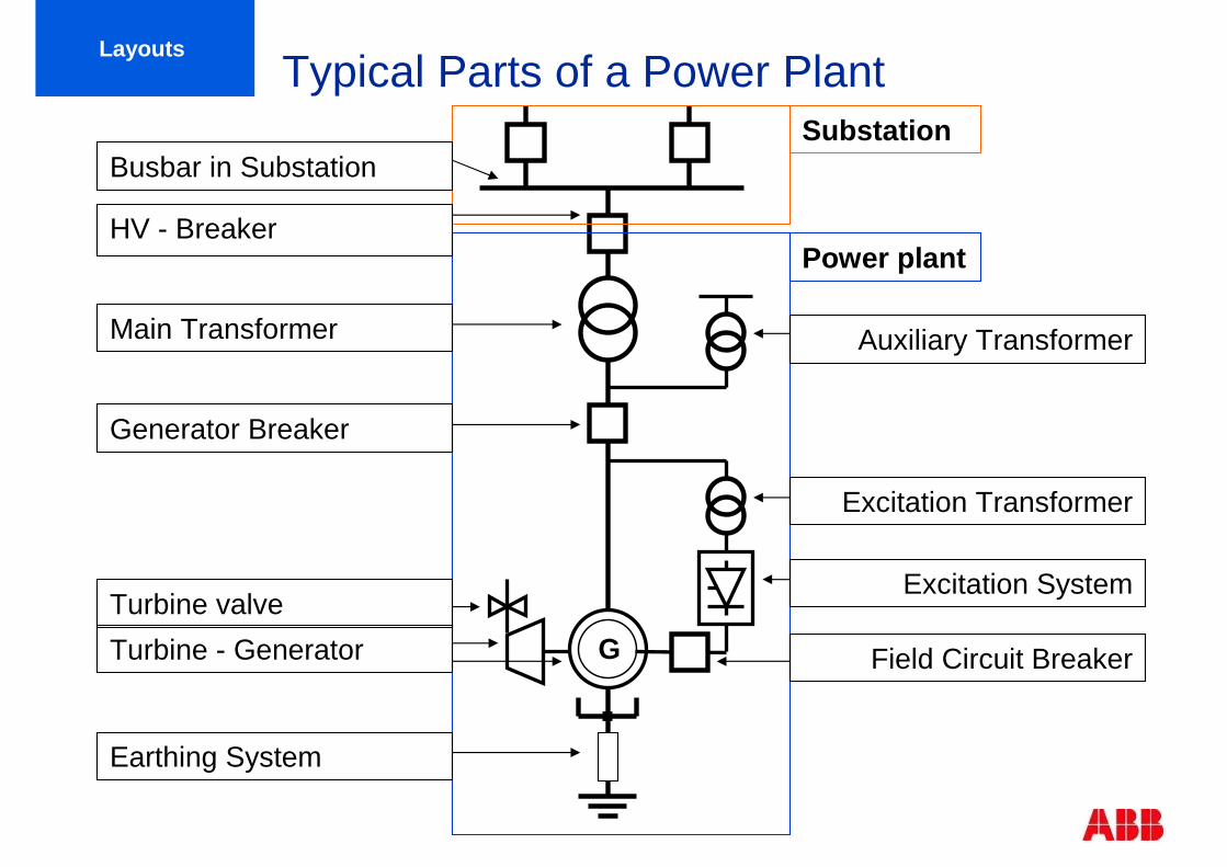
Typical Parts of a Power PlantLayouts
G
Substation
Power plant
Busbar in Substation
HV - Breaker
Main Transformer Auxiliary Transformer
Generator Breaker
Excitation Transformer
Excitation System
Field Circuit Breaker
Turbine valve
Turbine - Generator
Earthing System
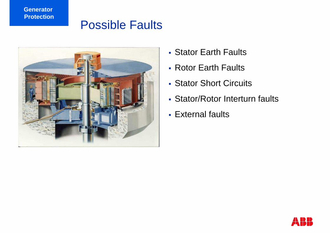
Possible Faults
� Stator Earth Faults
� Rotor Earth Faults
� Stator Short Circuits
� Stator/Rotor Interturn faults
� External faults
Generator Protection

� overcurrent/overload
� unbalanced load
� overtemperature
� over- and undervoltage
� over- and underexcitation
� over- and underfrequency
� over-fluxing
� asynchronous running
� out of step
� generator motoring
� failures in the machine control system (i.e. AVR or governor failure)
� failures in the machine cooling system
� failures in the primary equipment (i.e. breaker head flashover)
� open phase
Abnormal Operating ConditionGenerator Protection
© ABB Group October 10, 2011 | Slide 6
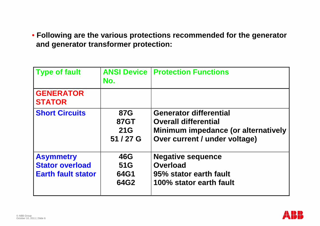
Type of fault ANSI DeviceNo.
Protection Functions
GENERATORSTATORShort Circuits 87G
87GT21G
51 / 27 G
Generator differentialOverall differentialMinimum impedance (or alternativelyOver current / under voltage)
AsymmetryStator overloadEarth fault stator
46G51G
64G164G2
Negative sequenceOverload95% stator earth fault100% stator earth fault
• Following are the various protections recommended f or the generator and generator transformer protection:
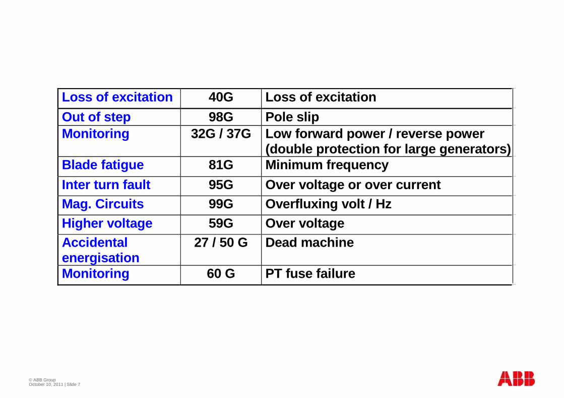
© ABB Group October 10, 2011 | Slide 7
Loss of excitation 40G Loss of excitation
Out of step 98G Pole slipMonitoring 32G / 37G Low forward power / reverse power
(double protection for large generators)Blade fatigue 81G Minimum frequency
Inter turn fault 95G Over voltage or over currentMag. Circuits 99G Overfluxing volt / HzHigher voltage 59G Over voltageAccidentalenergisation
27 / 50 G Dead machine
Monitoring 60 G PT fuse failure
© ABB Group October 10, 2011 | Slide 8
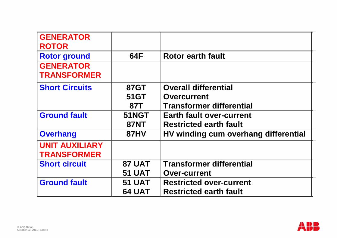
GENERATORROTORRotor ground 64F Rotor earth faultGENERATORTRANSFORMER
Short Circuits 87GT51GT87T
Overall differentialOvercurrentTransformer differential
Ground fault 51NGT87NT
Earth fault over-currentRestricted earth fault
Overhang 87HV HV winding cum overhang differentialUNIT AUXILIARYTRANSFORMERShort circuit 87 UAT
51 UATTransformer differentialOver-current
Ground fault 51 UAT64 UAT
Restricted over-currentRestricted earth fault

© ABB Group October 10, 2011 | Slide 9
1) Instruments
Field windingground-faultRAGRA(RXNB4)
64F
50/51
Unit aux.transformer
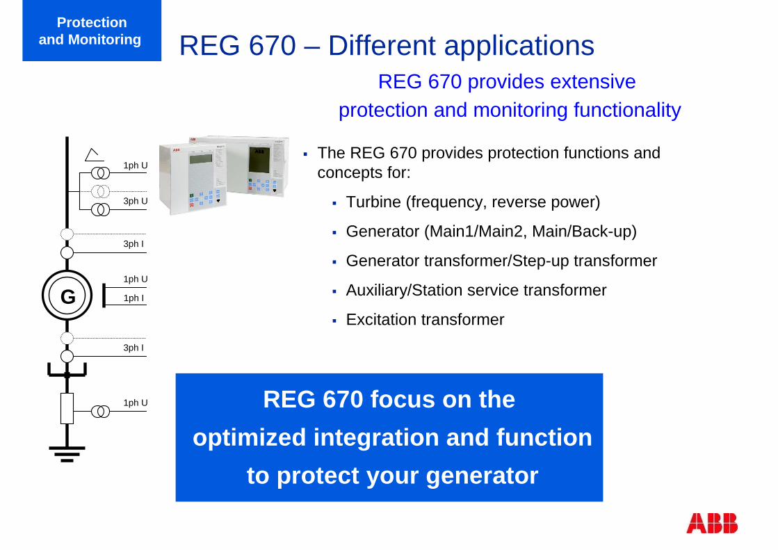
REG 670 – Different applications
� The REG 670 provides protection functions and concepts for:
� Turbine (frequency, reverse power)
� Generator (Main1/Main2, Main/Back-up)
� Generator transformer/Step-up transformer
� Auxiliary/Station service transformer
� Excitation transformer
REG 670 provides extensiveprotection and monitoring functionality
Protectionand Monitoring
REG 670 focus on the
optimized integration and function
to protect your generator
G
1ph U
3ph U
3ph I
3ph I
1ph U
1ph U
1ph I
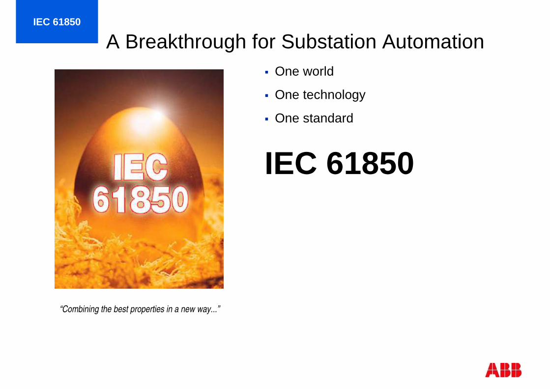
A Breakthrough for Substation Automation� One world
� One technology
� One standard
IEC 61850
“Combining the best properties in a new way...”
IEC 61850

© ABB Group October 10, 2011 | Slide 12

© ABB Group October 10, 2011 | Slide 13
Power transformers in a power system
400 kV AC Transmission
Generation
130 kV Subtransmission
Distribution
M
MV
LV
© ABB Group October 10, 2011 | Slide 14
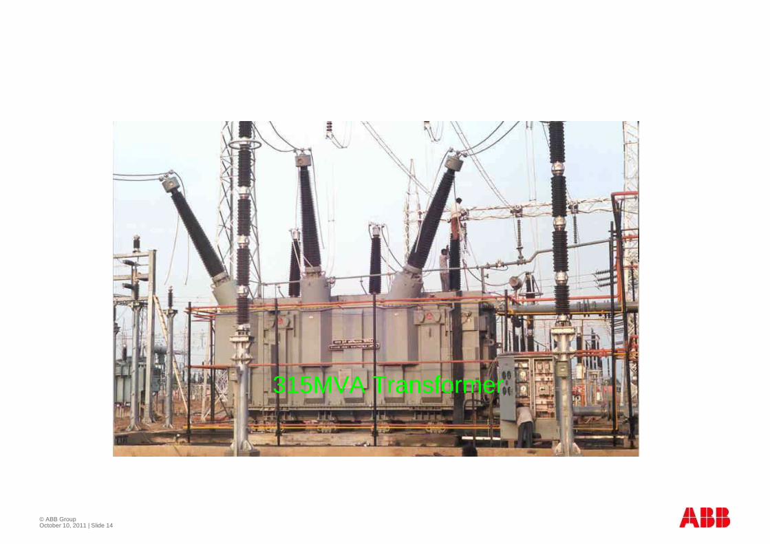
315MVA Transformer
© ABB Group October 10, 2011 | Slide 15
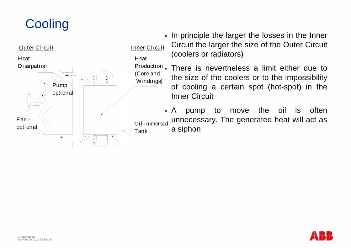
Cooling� In principle the larger the losses in the Inner
Circuit the larger the size of the Outer Circuit (coolers or radiators)
� There is nevertheless a limit either due to the size of the coolers or to the impossibility of cooling a certain spot (hot-spot) in the Inner Circuit
� A pump to move the oil is often unnecessary. The generated heat will act as a siphon
F anoptional
Pumpoptional
Outer Ci rcui t I nner Ci rcui t
Oi l immersedTank
HeatProduction(Core andWindings)
HeatDissipation
© ABB Group October 10, 2011 | Slide 16
Types of Internal Faults
� Earth faults
� Short-circuits
� Inter turn Faults
� Core Faults
� Tank Faults
� Reduced cooling
© ABB Group October 10, 2011 | Slide 17
Abnormal Conditions
� Overload
� Over voltage
� Reduced system voltage
� Over excitation
© ABB Group October 10, 2011 | Slide 18
Overload Capability
� It is possible to overload power transformers
� Older transformers may withstand 140% continuously
� Overloading and loss of cooling causes overheating

© ABB Group October 10, 2011 | Slide 19
Protective Relays Used ( Transformers > 5 MVA)
� Gas detector relay ( Buchholz)
� Over load protection
� Thermal relays
� Temperature monitoring relays
� Over current protection
� Ground fault protection
� Differential protection
� Interturn faults
� Pressure relay for tap changer
� Oil level monitor
© ABB Group October 10, 2011 | Slide 20
Protective Relays Used ( Transformers < 5 MVA)
� Gas detector relay
� Overload protection
� Overcurrent protection
� Ground fault protection
© ABB Group October 10, 2011 | Slide 21
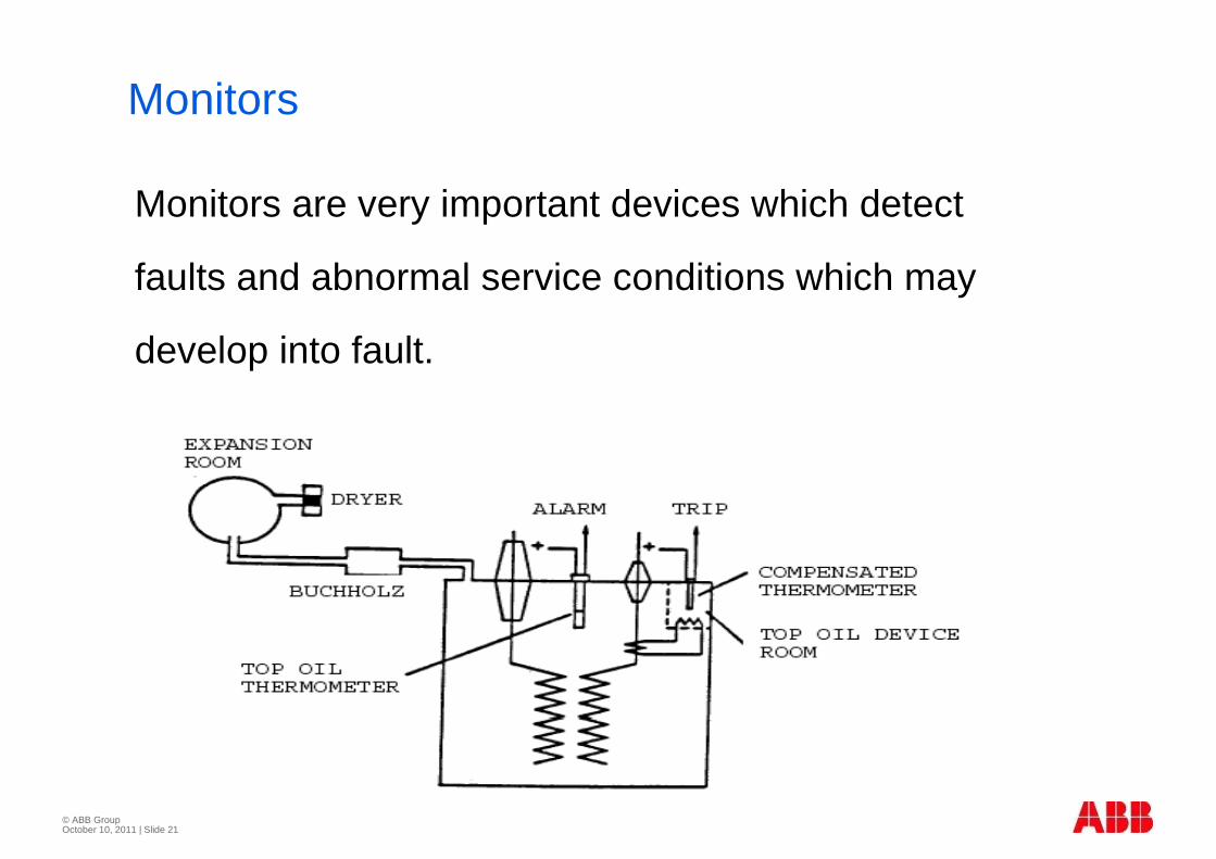
Monitors
Monitors are very important devices which detect
faults and abnormal service conditions which may
develop into fault.
© ABB Group October 10, 2011 | Slide 22
Transformer Monitors
� Mechanical fault detectors� Sudden gas pressure protection
� Buchholz protection
� Oil level monitoring
� Temperature Monitoring� The oil thermometer
� The winding thermometer
© ABB GroupNovember 2009 | Slide 23
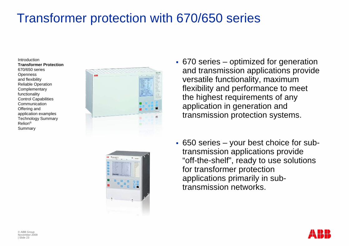
Transformer protection with 670/650 series
� 670 series – optimized for generation and transmission applications provide versatile functionality, maximum flexibility and performance to meet the highest requirements of any application in generation and transmission protection systems.
� 650 series – your best choice for sub-transmission applications provide “off-the-shelf”, ready to use solutions for transformer protection applications primarily in sub-transmission networks.
IntroductionTransformer Protection670/650 seriesOpennessand flexibilityReliable OperationComplementaryfunctionalityControl CapabilitiesCommunicationOffering andapplication examplesTechnology SummaryRelion®
Summary

© ABB GroupNovember 2009 | Slide 24
Fully compliant to the IEC 61850 standard
� Unrivalled compatibility for new and retrofit installations
� Designed for IEC 61850, implementing the core values of this standard
� Ensures open, future-proof and flexible system architectures, with state-of-the-art performance
� Interoperates with other IEC 61850 compliant IEDs
Introduction Line Distance Protection670/650 seriesReliable OperationComplementaryfunctionalityControl CapabilitiesCommunicationOffering andapplication examplesTechnology SummaryRelion®
Summary
© ABB Group October 10, 2011 | Slide 25

© ABB Group October 10, 2011 | Slide 26
The reactor absorbs the capacitive power generated in long lines

© ABB Group October 10, 2011 | Slide 27
Shunt Reactor

© ABB Group October 10, 2011 | Slide 28
L R
A B C A B C
L p L p L p
L n
© ABB Group October 10, 2011 | Slide 29
General
� Shunt reactors are used in EHV systems to limit the over voltages due to capacitive VAR generation in Long Transmission Lines
� The shunt reactors are normally connected� Through isolators to a line
� Through circuit breakers to a busbar
� Through circuit breakers to the tertiary of a Interconnecting transformer

© ABB Group October 10, 2011 | Slide 30
Different locations of reactor

© ABB Group October 10, 2011 | Slide 31
Internal FaultsFaults occur in shunt reactors due to insulation breakdown, ageing of insulation, overheating due to over excitation, oil contamination and leakage
Dry air-core reactors� Phase-to-phase faults , resulting in high magnitude phase
current
� Phase-to-earth faults ,, resulting in a low-magnitude earth-fault current, dependent upon the size of the system earthing.
� Turn-to-turn faults within the reactor bank, resulting in a very small change in phase current
� Oil-immersed reactors� High current phase-to-phase and phase-to-earth faults.
� Turn-to-turn faults within the reactor winding.
� Miscellaneous failures such as loss of cooling or low oil
© ABB Group October 10, 2011 | Slide 32
Abnormal Conditions
� Inrush currents
� Inrush currents flow in connection with energisation
� Inrush currents usually lower than 200% of rated current
� Transient overvoltages
� Temporary overvoltages
© ABB Group October 10, 2011 | Slide 33
Shunt Reactor Protections
� Differential protection
� Distance protection
� Phase over current protection
� Restricted earth fault protection
� Mechanical fault detectors
� Oil temperature and winding temperature protection

© ABB Group October 10, 2011 | Slide 34
Monitors
Monitors are very important devices which detect
faults and abnormal service conditions which may
develop into fault.
© ABB Group October 10, 2011 | Slide 35
Reactor Monitors
� Mechanical fault detectors� Sudden gas pressure protection
� Buchholz protection
� Oil level monitoring
� Temperature Monitoring� The oil thermometer
� The winding thermometer

© ABB GroupNovember 2009 | Slide 36
Shunt reactor protection and control
� Protection
� Phase segregated biased differential protection
� Low impedance restricted earth-fault
� High impedance differential protection
� Switching control for lines and buses
IntroductionTransformer Protection670/650 seriesOpennessand flexibilityReliable OperationComplementaryfunctionalityControl CapabilitiesCommunicationOffering andapplication examplesTechnology SummaryRelion®
Summary
© ABB Group October 10, 2011 | Slide 37
© ABB Group October 10, 2011 | Slide 38
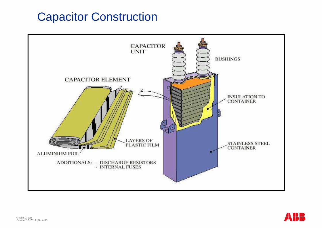
Capacitor Construction

© ABB Group October 10, 2011 | Slide 39
Power Factor CorrectionPower Factor Correction
� KW is the Working Power component
� kVAR is the Non- Working Power or Reactive Power component to serve inductive loads, which require magnetizing current:
Motors, Transformers, Lighting ballast
� KVA is the Total Power required to serve a load
� Capacitors supply the reactive power component
� Power Factor is a measurement of how efficiently power is being used.
Working Power (kW)
Reactive Power (kVAR)

© ABB Group October 10, 2011 | Slide 40
Increased System CapacityIncreased System Capacity
� By supplying reactive current (kVAR) close to the load, capacitors release system capacity on the entire system and reduce costs.
Power Factor 60% 70% 80% 90% 100%Real Power kW 600 600 600 600 600
Reactive Power kVAR 800 612 450 291 Zero
Total Power kVA 1000 857 750 667 600
Total Power (KVA) = Working Power (KW) ÷÷÷÷ Power Factor
Extra capacity for more KVA
released system capacity

© ABB Group October 10, 2011 | Slide 41
Voltage StabilityVoltage Stability
� A feeder circuit will have a voltage drop related to the impedance of the line and the power factor
� Adding capacitance will actually cause a voltage rise by supplying reactive current to the bus
(less current = less voltage drop)
© ABB Group October 10, 2011 | Slide 42
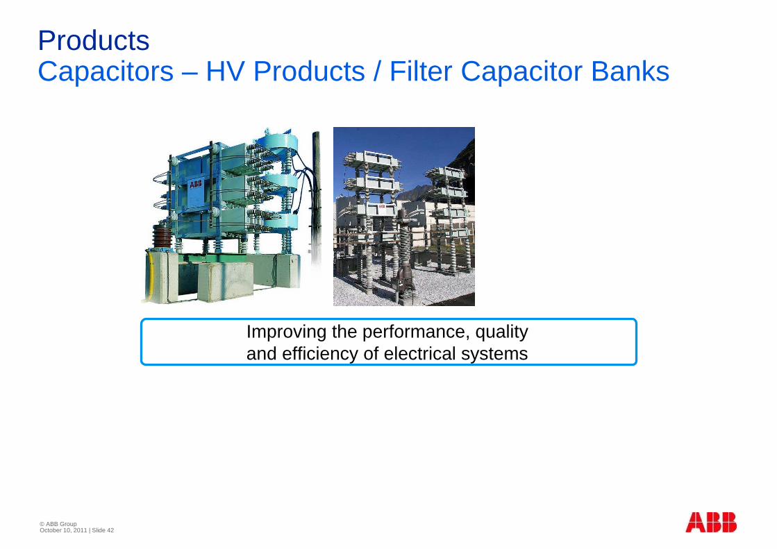
ProductsCapacitors – HV Products / Filter Capacitor Banks
Improving the performance, quality and efficiency of electrical systems
Capacitor banks- General
� Normally used in MV networks to generate reactive power
� Series reactors are used to limit inrush current
� Harmonic filters for thyristor controlled reactors are also variation of capacitor banks having reactance tuned to capacitance

�Shunt Capacitors -General
Shunt Capacitor Faults
� Terminal shunt faults
� Capacitor unit failures
� Capacitor unit over voltages
� Capacitor rack arc-over
Abnormal Conditions
� Inrush currents
� Transient over voltages
� Temporary over voltages
� Out rush currents
Capacitor Bank Protections
� Short -circuit protection (3I >>)
� Ground-fault protection (I )
� Overload protection(3I/U >)
� Under current protection (I/U <)
� Unbalance protection (IN-N)
© ABB Group October 10, 2011 | Slide 48
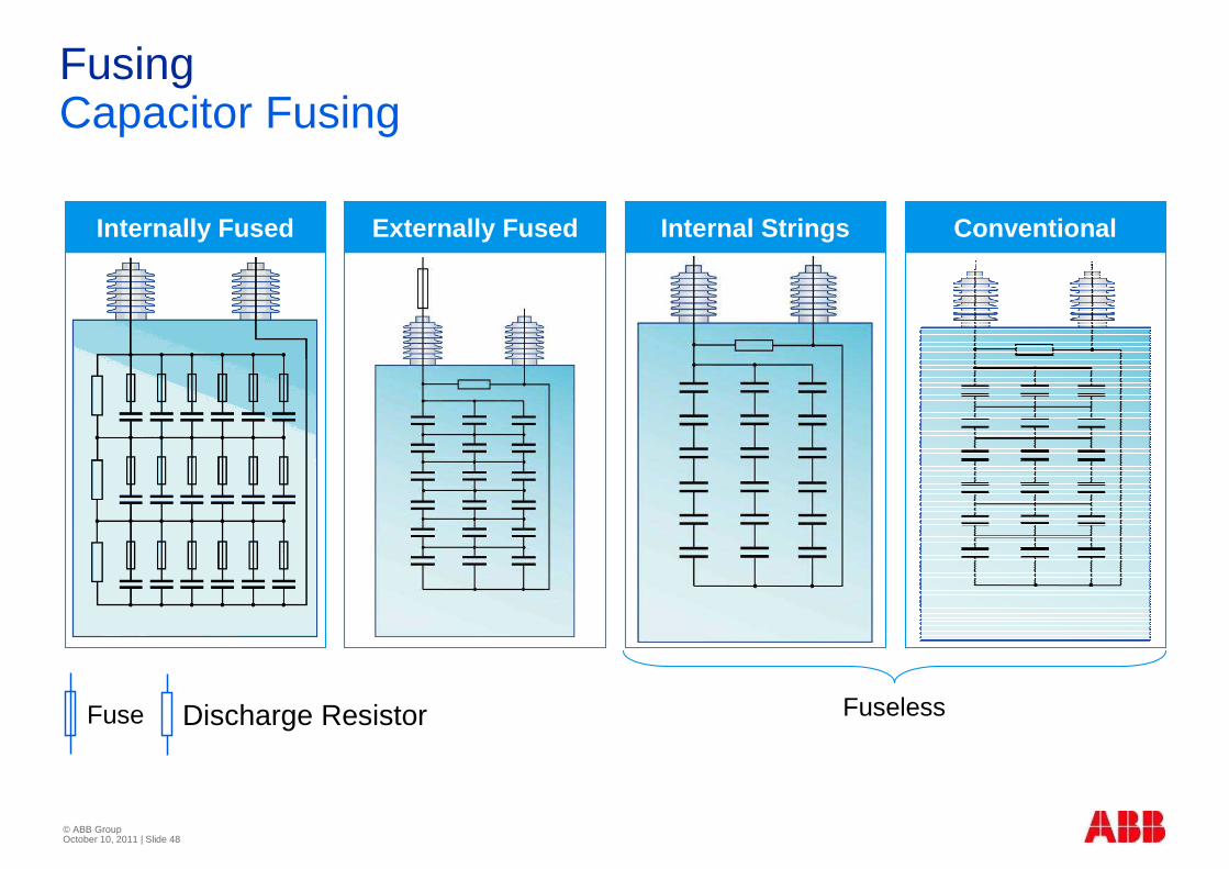
FusingCapacitor Fusing
Internally Fused Externally Fused Internal Strings Conventional
FuselessFuse Discharge Resistor
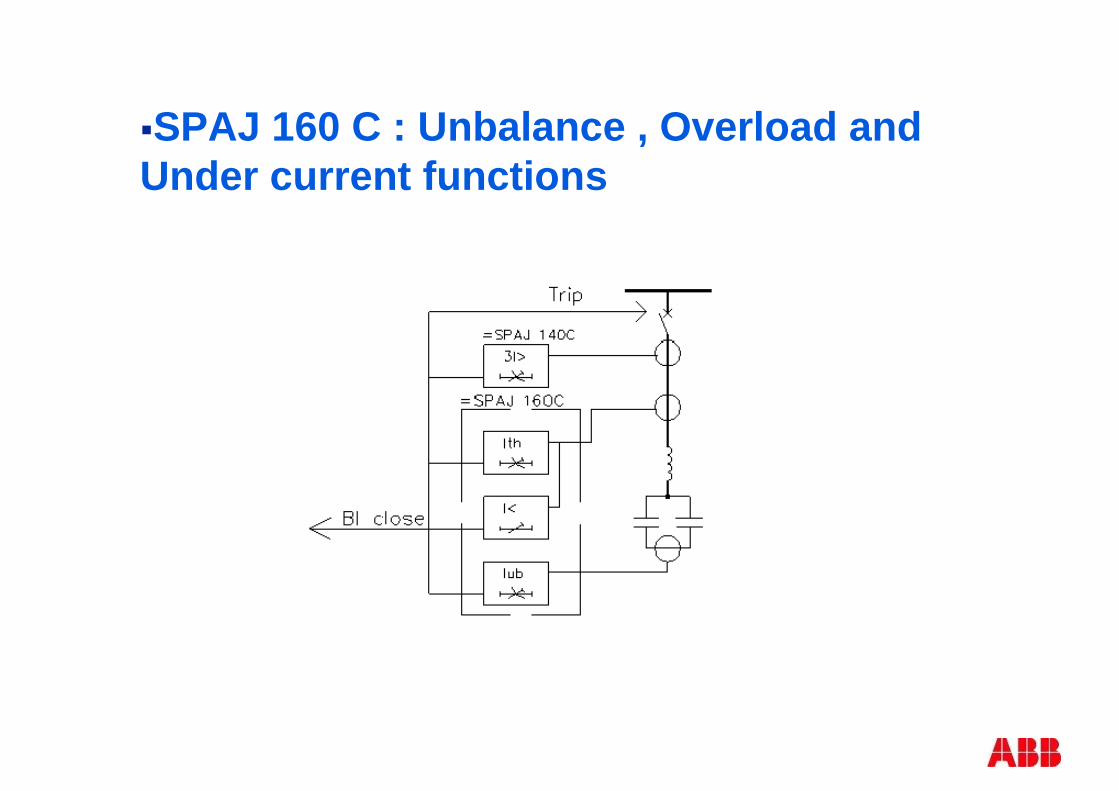
�SPAJ 160 C : Unbalance , Overload and Under current functions
© ABB Group October 10, 2011 | Slide 50
Protection Application – An Overview
Part 2B
Bapuji S Palki, INCRC/PowerTechnologies, 15-11-200 9
© ABB Group October 10, 2011 | Slide 51
© ABB Group October 10, 2011 | Slide 52
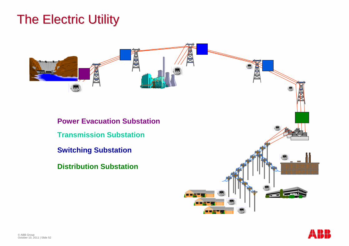
The Electric UtilityThe Electric Utility
Power Evacuation Substation
Transmission Substation
Switching Substation
Distribution Substation
© ABB Group October 10, 2011 | Slide 53
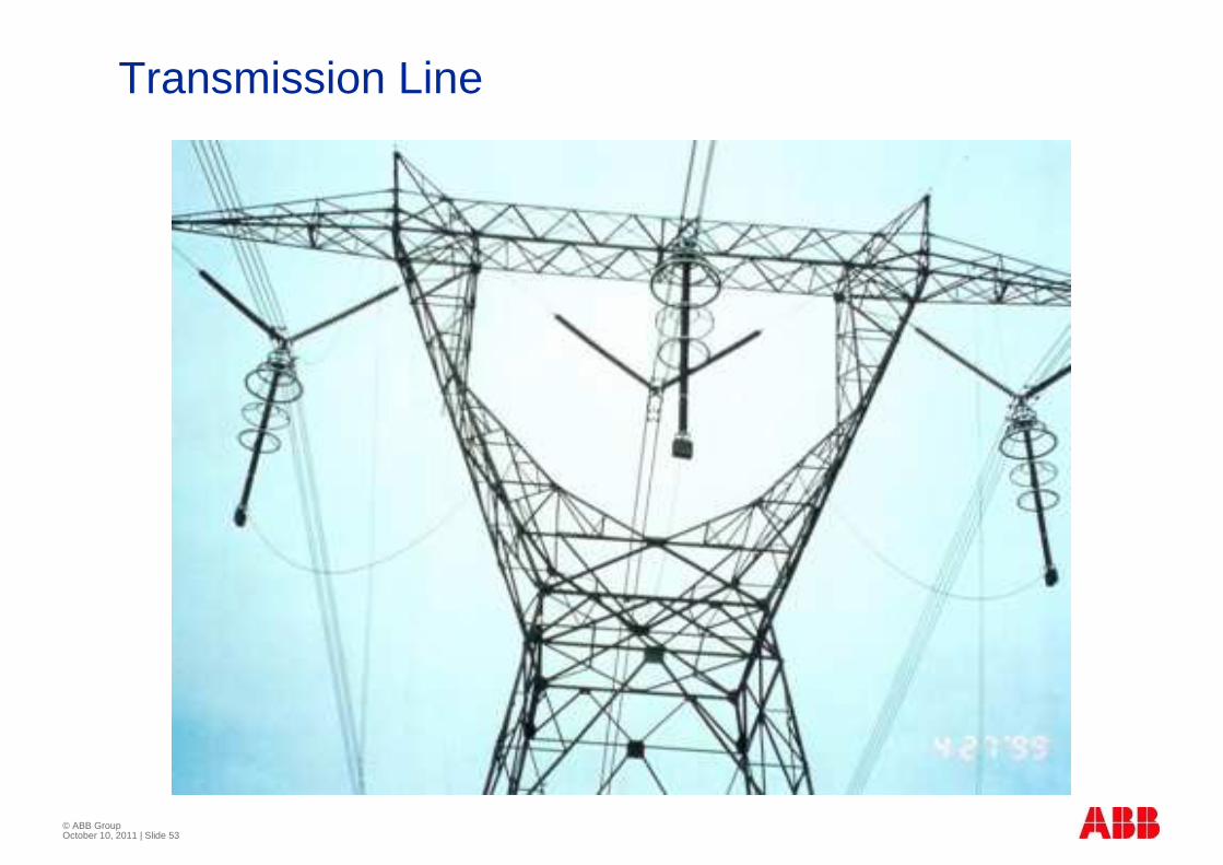
Transmission Line

© ABB Group October 10, 2011 | Slide 54
Electrical faults in the power system
� Transmission lines 85%
� Busbar 12%
� Transformer/ Generator 3%
100%

© ABB Group October 10, 2011 | Slide 55
Fault types
� Transient faults
� are common on transmission lines, approximately 80-85%
� lightnings are the most common reason
� can also be caused by birds, falling trees, swinging lines etc.
� will disappear after a short dead interval
� Persistent faults
� can be caused by a broken conductor fallen down
� can be a tree falling on a line
� must be located and repaired before normal service
© ABB Group October 10, 2011 | Slide 56
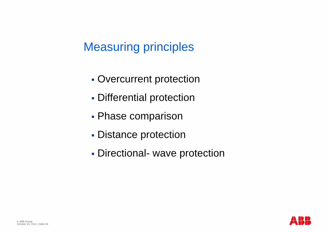
Measuring principles
� Overcurrent protection
� Differential protection
� Phase comparison
� Distance protection
� Directional- wave protection
© ABB Group October 10, 2011 | Slide 57
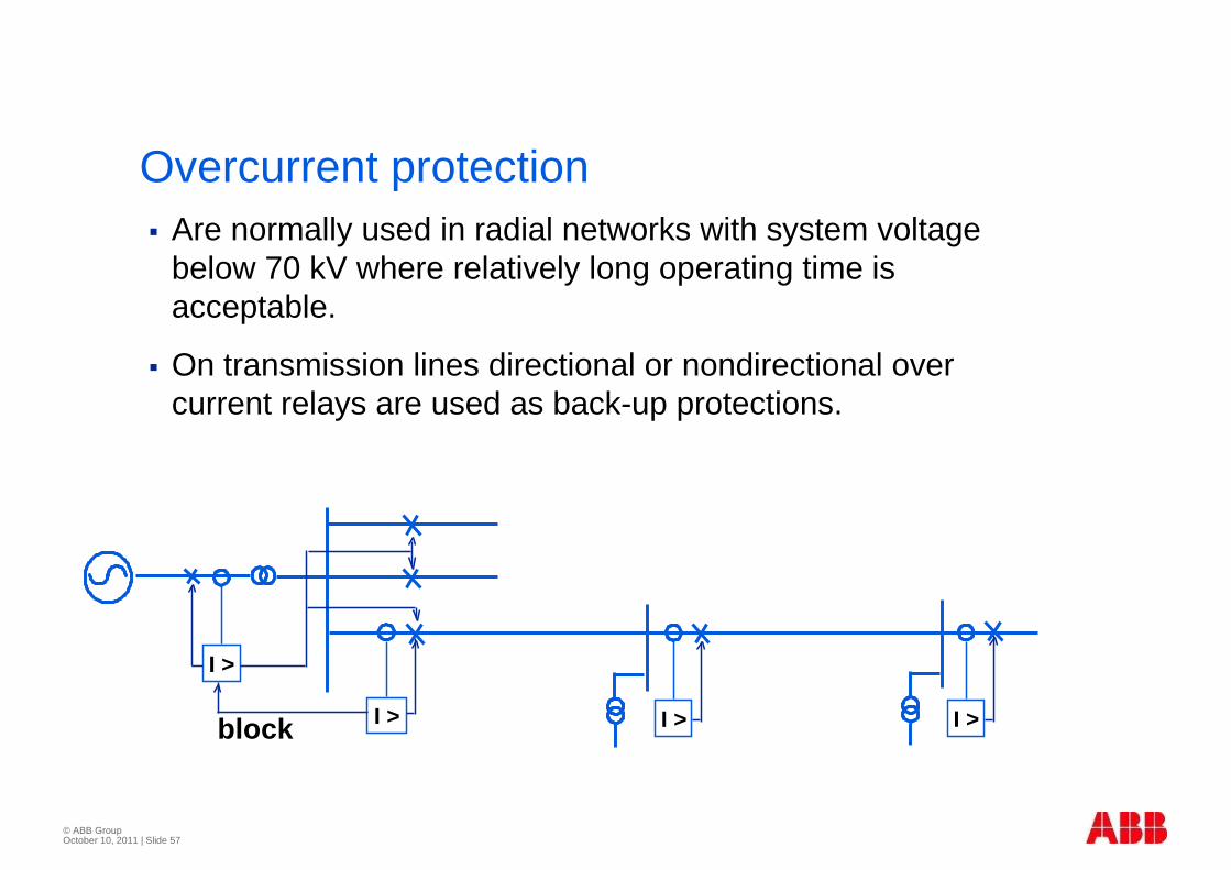
Overcurrent protection� Are normally used in radial networks with system voltage
below 70 kV where relatively long operating time is acceptable.
� On transmission lines directional or nondirectional over current relays are used as back-up protections.
I > I > I >
I >
block
© ABB Group October 10, 2011 | Slide 58
Pilot wire differential protection
� Pilot wires can be in soil or on towers.
� The resistance in the wires will limit the use on longer lines. The use is mostly restricted to distances up to 10 km.
© ABB Group October 10, 2011 | Slide 59
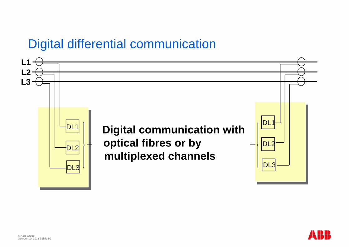
Digital differential communication
Digital communication withoptical fibres or by multiplexed channels
L1L2L3
DL1
DL2
DL3
DL1
DL2
DL3
© ABB Group October 10, 2011 | Slide 60
Phase comparison
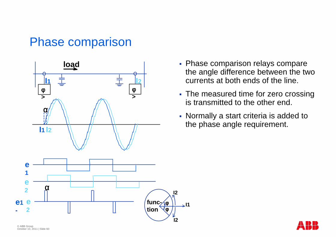
� Phase comparison relays compare the angle difference between the two currents at both ends of the line.
� The measured time for zero crossing is transmitted to the other end.
� Normally a start criteria is added to the phase angle requirement.
I1 I2
e1
e2
e2
e1-
φφφφ>
φφφφ>
I1 I2
load
I2
I2
I1func-tion
αααα
αααα
φφφφφφφφ
© ABB Group October 10, 2011 | Slide 61
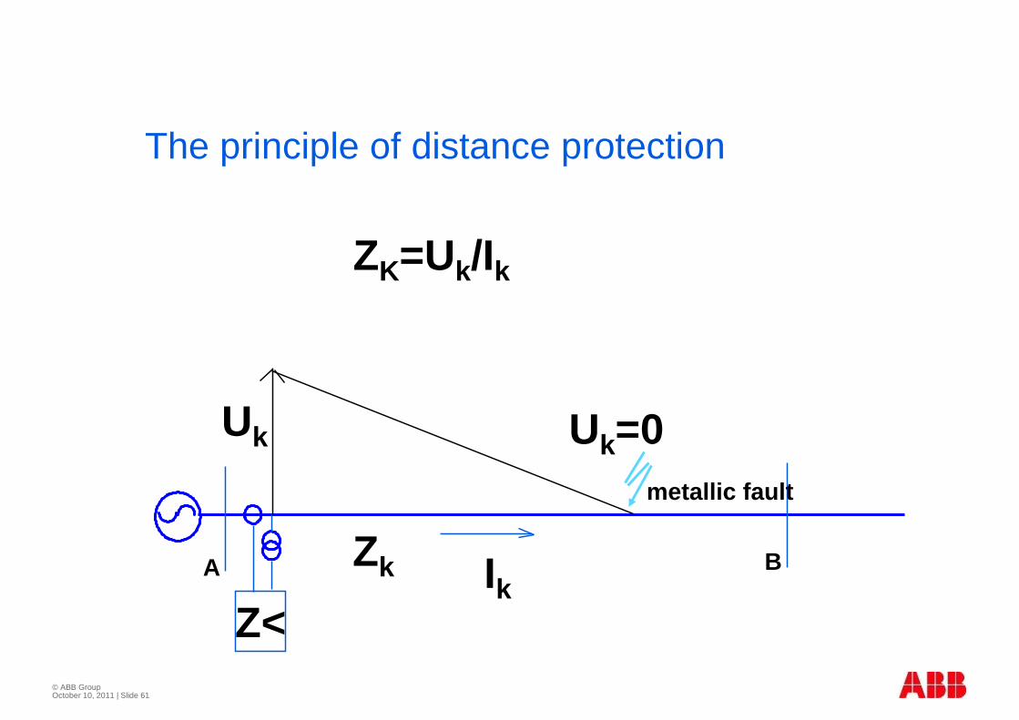
The principle of distance protection
Z<
ZK=Uk/Ik
Uk=0Uk
Zk IkA B
metallic fault
© ABB Group October 10, 2011 | Slide 62
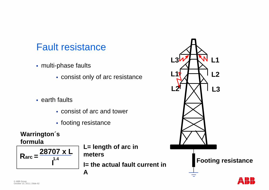
Fault resistance
� multi-phase faults
� consist only of arc resistance
� earth faults
� consist of arc and tower
� footing resistance
L1
L3
L3
L1
L2
L2
Footing resistanceRarc =
28707 x L 1.4I
Warrington´sformula
L= length of arc in meters
I= the actual fault current in A

© ABB Group October 10, 2011 | Slide 63
Distance protection on short lines
� Quadrilateral characteristic improves sensitivity for higher RF/XF ratio
� It still has some limitations:
� the value of set RF/XF ratio is limited to 5
jX
RXF
RF
© ABB Group October 10, 2011 | Slide 64
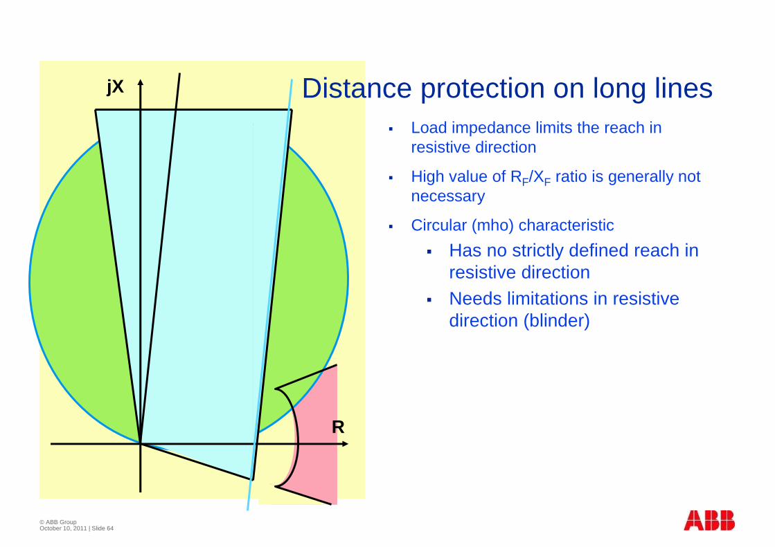
Distance protection on long lines� Load impedance limits the reach in
resistive direction
� High value of RF/XF ratio is generally not necessary
� Circular (mho) characteristic
� Has no strictly defined reach in resistive direction
� Needs limitations in resistive direction (blinder)
R
jX
© ABB Group October 10, 2011 | Slide 65
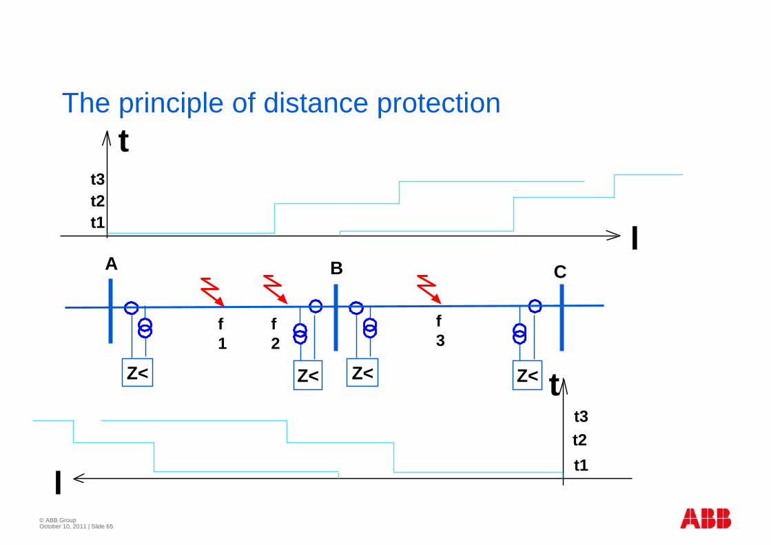
The principle of distance protection
A
Z<
B
Z< Z<
C
Z<
t
t
lt1
t2t3
lt1t2t3
f1
f2
f3
© ABB Group October 10, 2011 | Slide 66
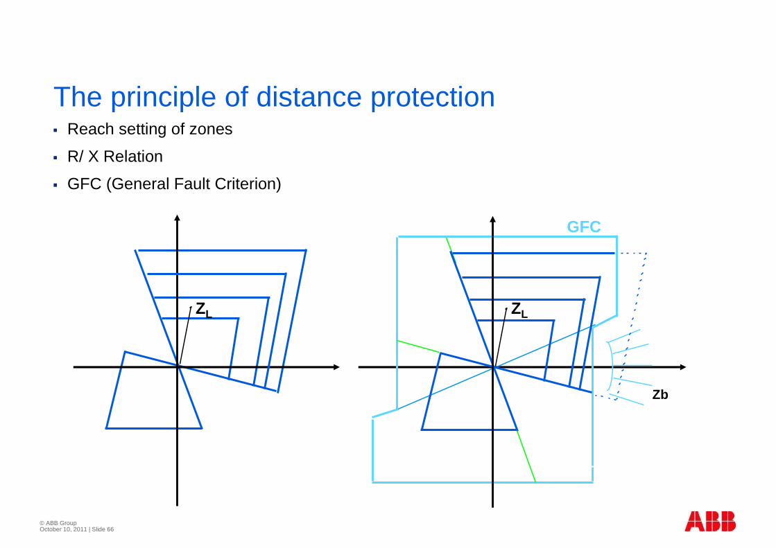
The principle of distance protection� Reach setting of zones
� R/ X Relation
� GFC (General Fault Criterion)
ZL
Zb
ZL
GFC
© ABB Group October 10, 2011 | Slide 67
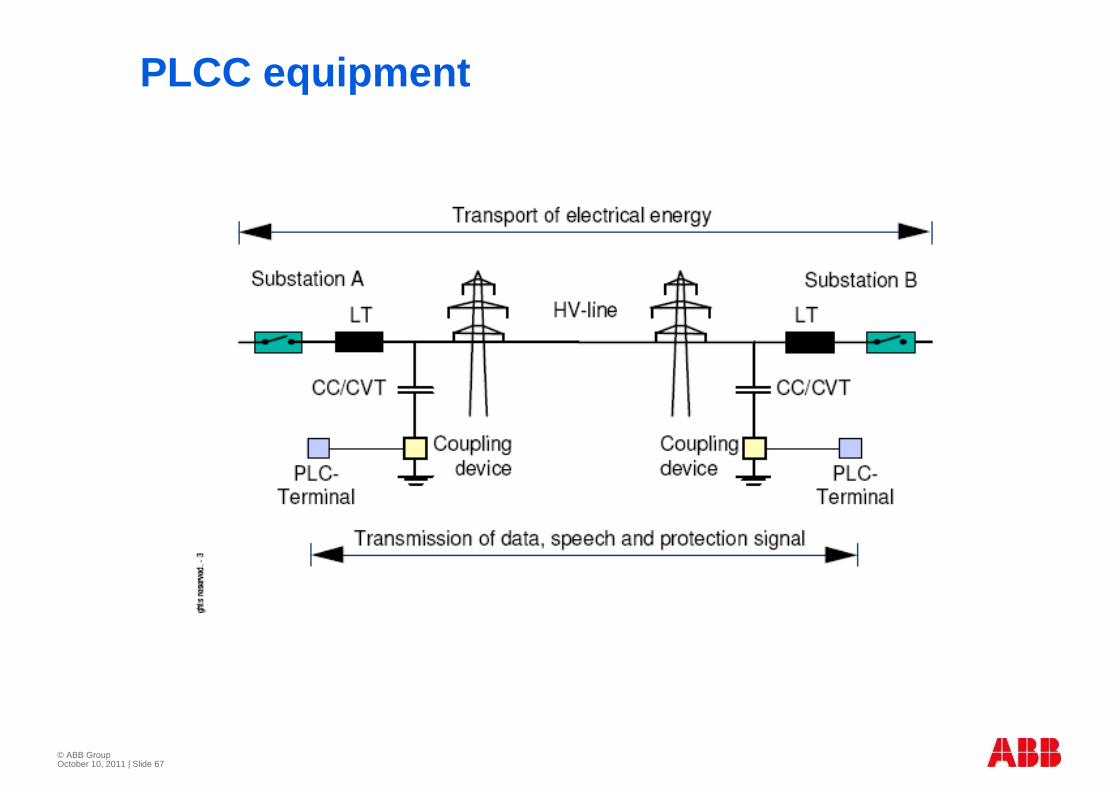
PLCC equipment
© ABB Group October 10, 2011 | Slide 68
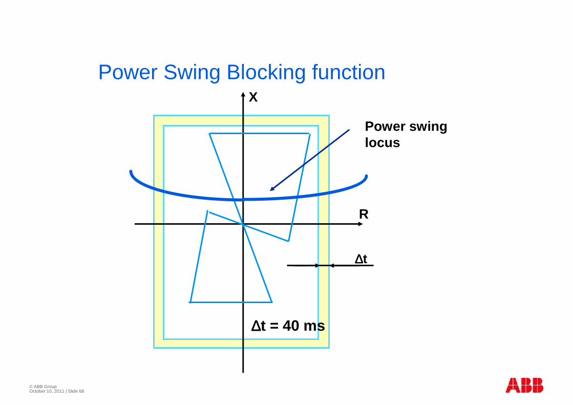
Power Swing Blocking function
∆∆∆∆t
∆∆∆∆t = 40 ms
X
R
Power swing locus

© ABB Group October 10, 2011 | Slide 69
Series compensated system
• Correct direction discrim-inationat voltage reversal (negative fault reactance)
• variation in resulted line impedance
Consideration for line distance protections
BA
F1
X =70%C X =100%l
R
jX
AB
B´
70%
100%
gape not flashed
gape flashed
© ABB GroupNovember 2009Slide 70
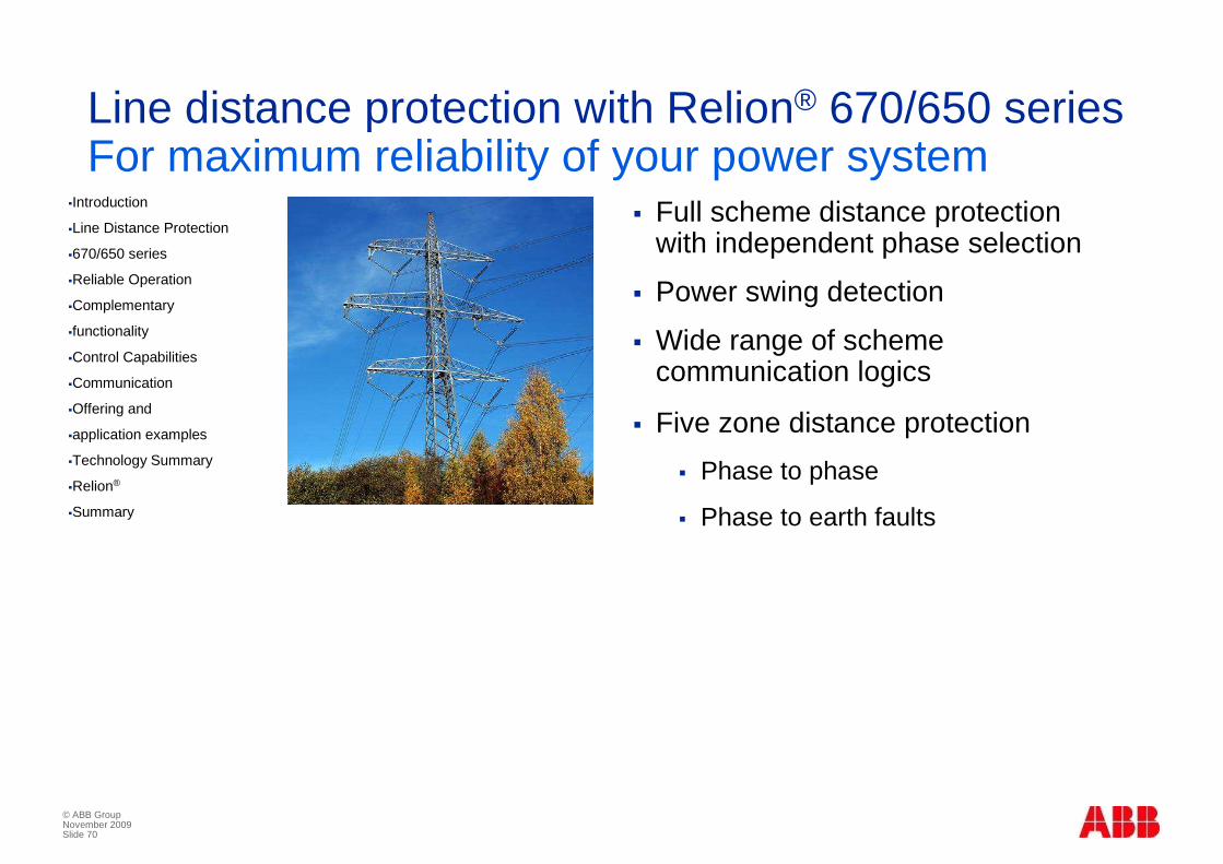
Line distance protection with Relion® 670/650 seriesFor maximum reliability of your power system
� Full scheme distance protection with independent phase selection
� Power swing detection
� Wide range of scheme communication logics
� Five zone distance protection
� Phase to phase
� Phase to earth faults
�Introduction
�Line Distance Protection
�670/650 series
�Reliable Operation
�Complementary
�functionality
�Control Capabilities
�Communication
�Offering and
�application examples
�Technology Summary
�Relion®
�Summary
© ABB GroupNovember 2009Slide 71
Fully compliant to the IEC 61850 standard
� Unrivalled compatibility for new and retrofit installations
� Designed for IEC 61850, implementing the core values of this standard
� Ensures open, future-proof and flexible system architectures, with state-of-the-art performance
� Interoperates with other IEC 61850 compliant IEDs
�Introduction
�Line Distance Protection
�670/650 series
�Reliable Operation
�Complementary
�functionality
�Control Capabilities
�Communication
�Offering and
�application examples
�Technology Summary
�Relion®
�Summary
© ABB Group October 10, 2011 | Slide 72
© ABB Group October 10, 2011 | Slide 73
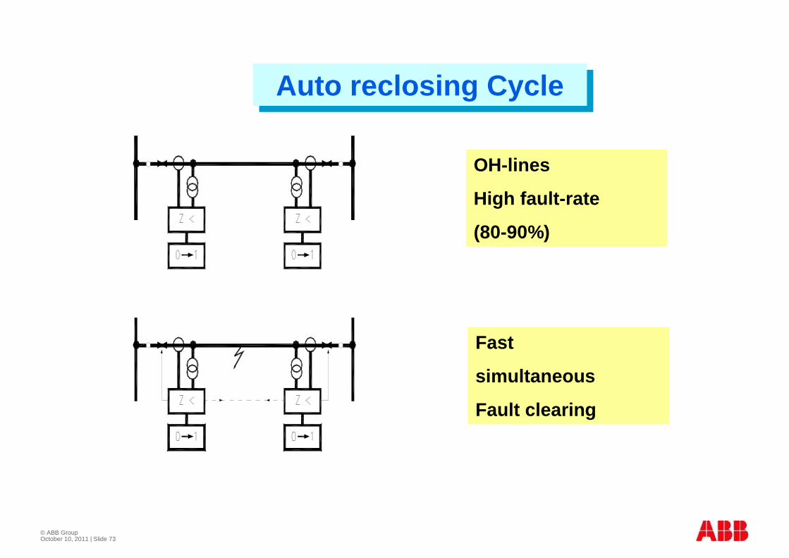
Auto reclosing CycleAuto reclosing Cycle
Fast
simultaneous
Fault clearing
OH-lines
High fault-rate
(80-90%)

© ABB Group October 10, 2011 | Slide 74
AUTORECLOSING CYCLEAUTORECLOSING CYCLE
OH-lines
Intermittent faults
(80-90%)
Successful
AR-rate :
High (80-90%)

© ABB Group October 10, 2011 | Slide 75
Auto reclosing principles
� 95% of faults are transient type
� 3 Ph autoreclosing synchrocheck is used
� Helps verify phase angles are not out of phase e.g: due to heavy power swing
� 1 Ph autoreclosing needs identification of faulty phase
� Phase identification is difficult for high resistance faults

© ABB Group October 10, 2011 | Slide 76
Single-pole Reclosing
A B C A B C
Single-Pole Reclosing

© ABB Group October 10, 2011 | Slide 77
Artificial extinction of secondary arc by Fixed Four-reactor Scheme
L R
A B C A B C
L p L p L p
L n
© ABB Group October 10, 2011 | Slide 78
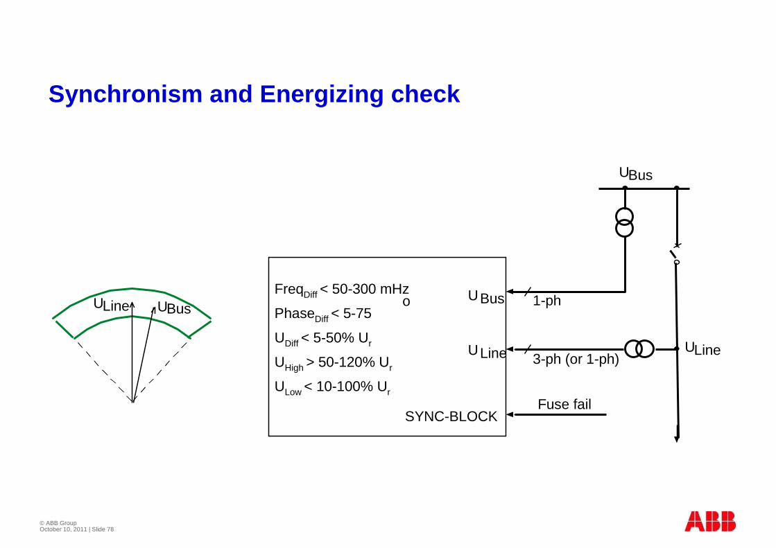
ULine UBus
SYNC-BLOCK
UBus
ULine
Fuse fail
1-ph
3-ph (or 1-ph)
UBus
ULineUHigh > 50-120% Ur
ULow < 10-100% Ur
PhaseDiff < 5-75
UDiff < 5-50% Ur
FreqDiff < 50-300 mHzo
Synchronism and Energizing check
© ABB Group October 10, 2011 | Slide 79
© ABB Group October 10, 2011 | Slide 80
Need for Busbar protection
� In its absence fault clearance takes place in Zone-II of distance relay by remote end tripping
� This means slow and unselective tripping and wide spread black out
Effect of delayed clearance
� Greater damage at fault point
� Indirect shock to connected equipments like shafts of Generator and windings of transformer.
© ABB Group October 10, 2011 | Slide 81
Types of BB Protections
� High impedance
� Medium impedance
� Low impedance
� Blockable O/C relay ( For radial systems in distribution systems)
© ABB Group October 10, 2011 | Slide 82
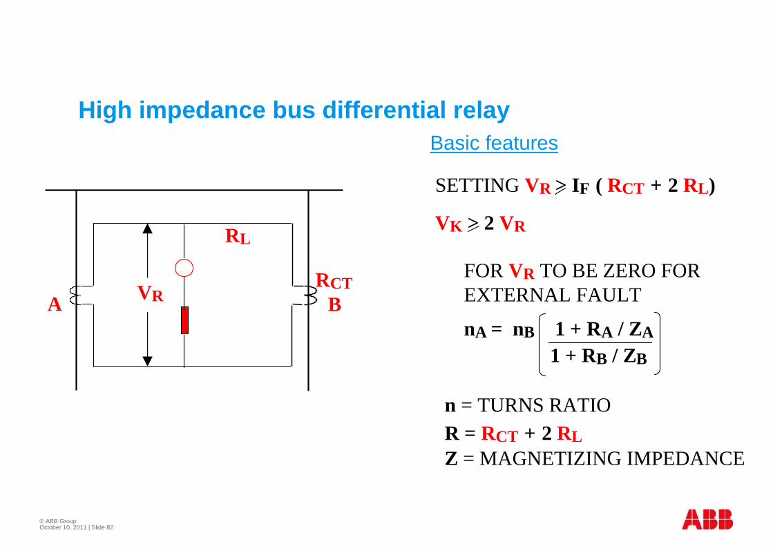
High impedance bus differential relayBasic features
SETTING VR > IF ( RCT + 2 RL)
VK > 2 VR
FOR VR TO BE ZERO FOREXTERNAL FAULT
nA = nB 1 + RA / ZA
1 + RB / ZB
n = TURNS RATIOR = RCT + 2 RLZ = MAGNETIZING IMPEDANCE
A BRCT
RL
VR
© ABB Group October 10, 2011 | Slide 83
Limitations of High impedance differential relay
� Puts stringent requirements on CTs
� Need for dedicated CTs
� Identical CT ratios , magnetising impedances
� Aux CTs not acceptable
� Inability to cope with increasing fault levels

© ABB Group October 10, 2011 | Slide 84
T MDn MD
D 1D 2
dR
IR1
Ud3
US
RADSS medium impedance relay
© ABB Group October 10, 2011 | Slide 85
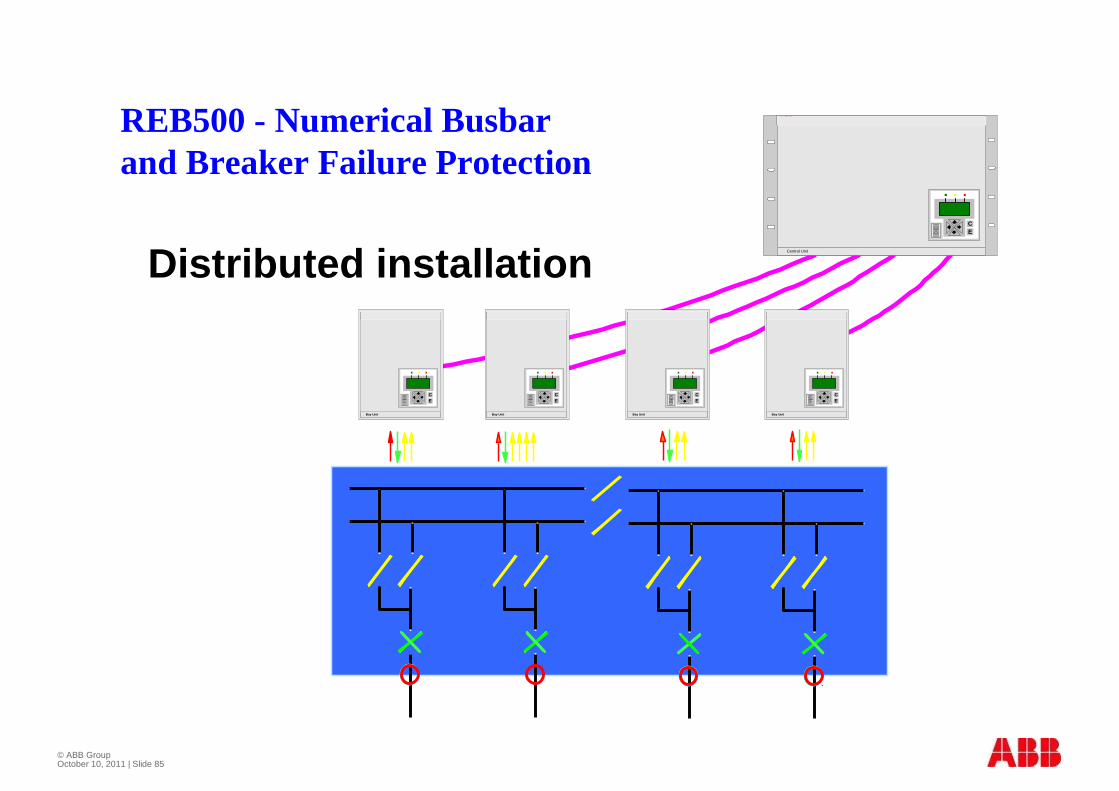
Distributed installationABB Network Partner AG REB 500
Bay Unit
CE
ABB Network Partner AG REB 500
Bay Unit
CE
ABB Network Partner AG REB 500
Bay Unit
CE
ABB Network Partner AG REB 500
Bay Unit
CE
Central Unit
ABB Network Partner AG REB 500
CE
REB500 - Numerical Busbarand Breaker Failure Protection
© ABB Group October 10, 2011 | Slide 86
Advantages of medium/ Low impedance relays
� Free from any need for Identical CT ratios or matched CTs
� Other relays can be included in the same CT core
� Increasing fault levels have no impact

© ABB Group October 10, 2011 | Slide 87
Diff. relay
1000/5 200/5 500/5
3.5 A 5 A5 A
500 A200 A700 A
0.7 A 0.2 A 0.5 A
5/1 5/0.2 5/0.5
RADSS IN SINGLE BUS
© ABB Group October 10, 2011 | Slide 88
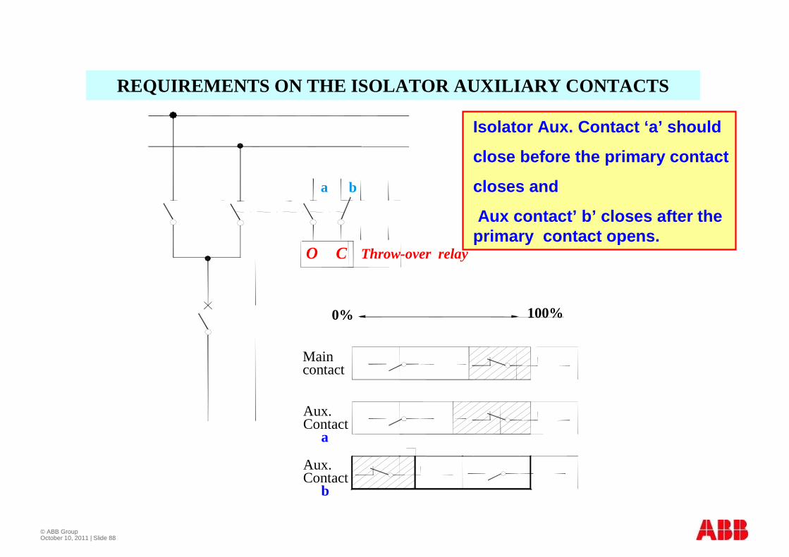
REQUIREMENTS ON THE ISOLATOR AUXILIARY CONTACTS
Isolator Aux. Contact ‘a’ should
close before the primary contact
closes and
Aux contact’ b’ closes after the primary contact opens.
Throw-over relay
100%0%
Maincontact
Aux.Contact
a
Aux.Contact
b
a b
O C
© ABB Group October 10, 2011 | Slide 89
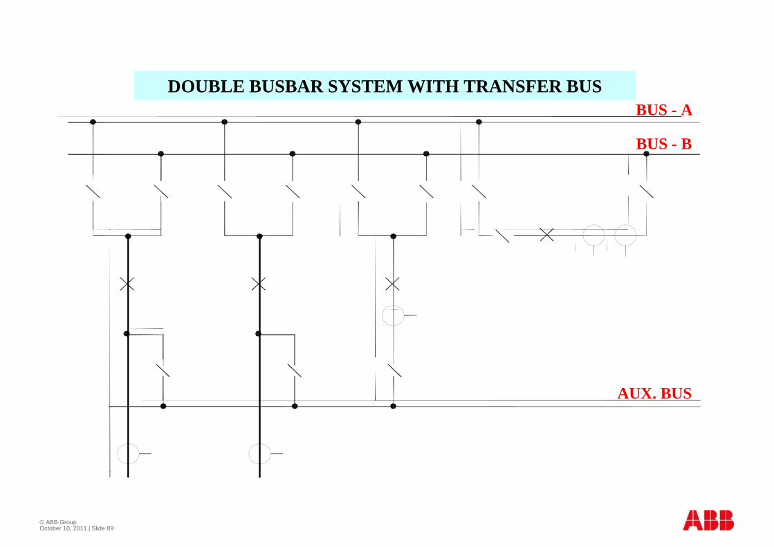
DOUBLE BUSBAR SYSTEM WITH TRANSFER BUSBUS - A
BUS - B
AUX. BUS
© ABB Group October 10, 2011 | Slide 90
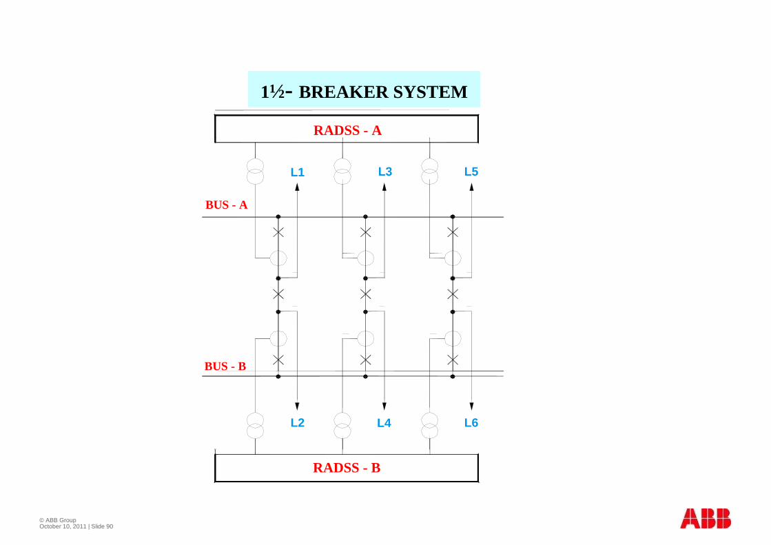
1½- BREAKER SYSTEM
RADSS - A
RADSS - B
BUS - A
BUS - B
L1 L3 L5
L4 L6L2
© ABB Group April 2009Slide 91
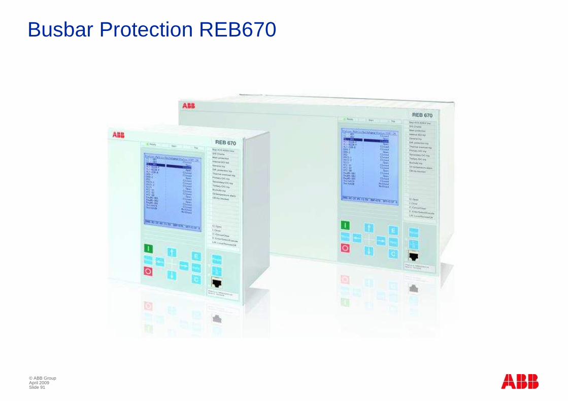
Busbar Protection REB670

© ABB Group October 10, 2011 | Slide 92
© ABB Group October 10, 2011 | Slide 93
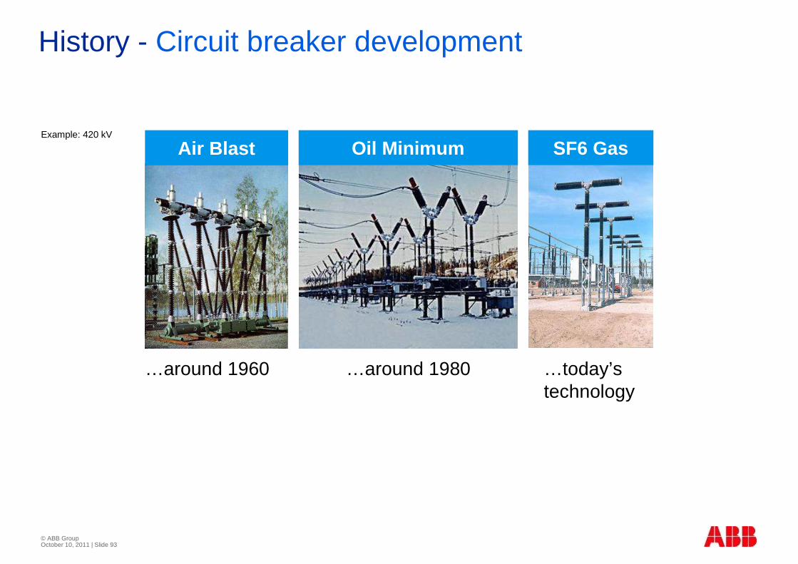
History - Circuit breaker development
Air Blast Oil Minimum SF6 GasExample: 420 kV
…around 1960 …around 1980 …today’s technology
© ABB Group October 10, 2011 | Slide 94
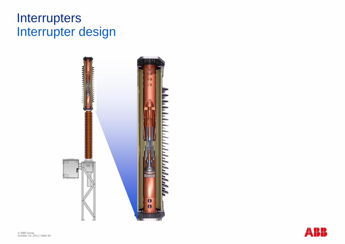
InterruptersInterrupter design
© ABB Group October 10, 2011 | Slide 95
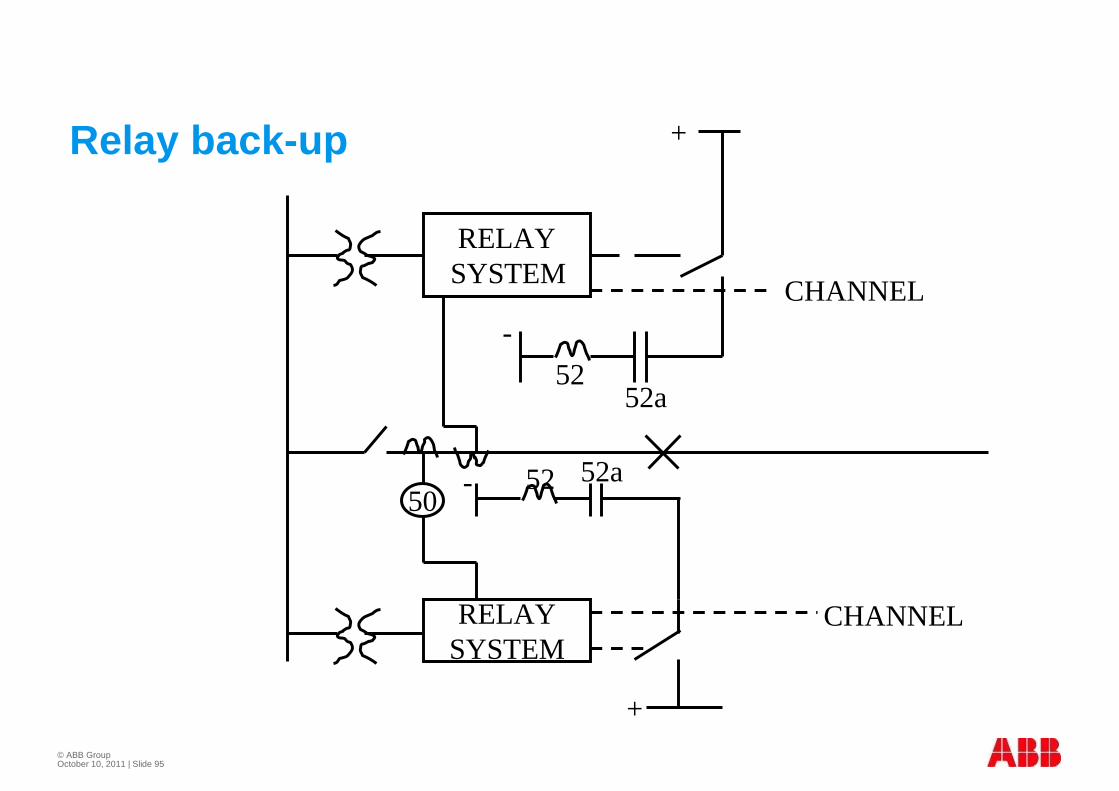
Relay back -up
RELAYSYSTEM
RELAYSYSTEM
50
+
+
-
- 52 52a
5252a
CHANNEL
CHANNEL
© ABB Group October 10, 2011 | Slide 96
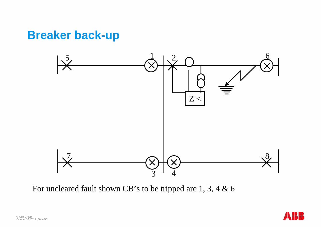
For uncleared fault shown CB’s to be tripped are 1, 3, 4 & 6
Breaker back -up
Z <
5 1
7
3 4
2 6
8
© ABB Group October 10, 2011 | Slide 97
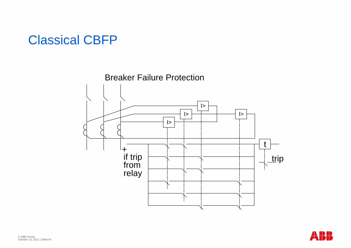
Classical CBFP
I>
I>
I>
I>
t
Breaker Failure Protection
trip+if tripfromrelay

© ABB Group October 10, 2011 | Slide 98
© ABB Group October 10, 2011 | Slide 99
Introduction� Majority faults are earth faults
� Earth fault protection depends on type of earthing
� Effectively earthed
� Reactance earthed
� High resistance earthed
� Resonance earthed
© ABB Group October 10, 2011 | Slide 100
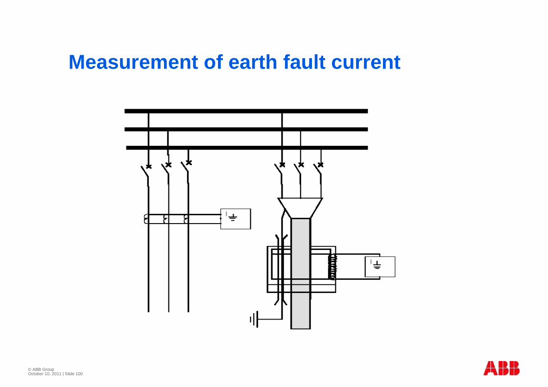
Measurement of earth fault current
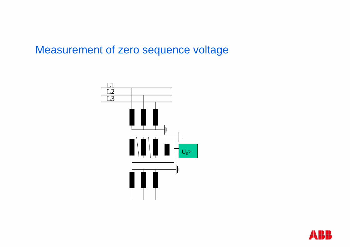
Measurement of zero sequence voltage
U0>
L1L2L3
© ABB Group October 10, 2011 | Slide 102
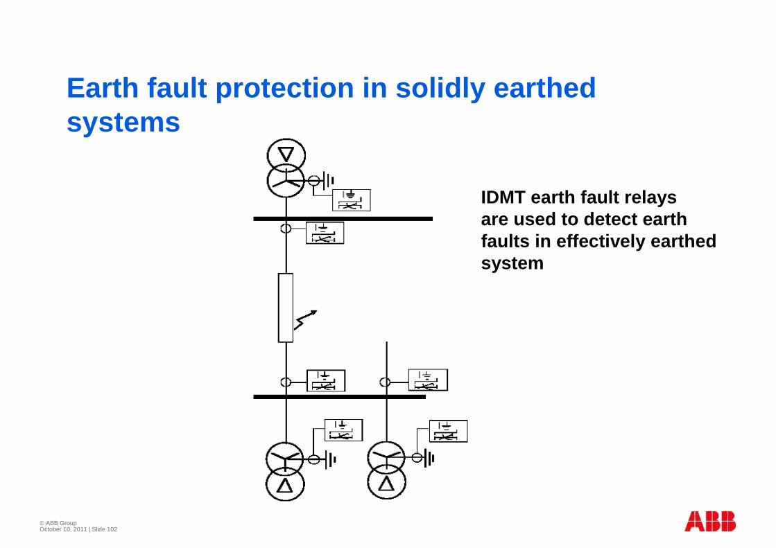
Earth fault protection in solidly earthed systems
IDMT earth fault relays are used to detect earth faults in effectively earthed system
© ABB Group October 10, 2011 | Slide 103
Directional Earth Fault Relay
� Directional earth fault relays are used
� Can use communication link
� Inrush current stabilization may be required for sensitive settings
© ABB Group October 10, 2011 | Slide 104
Directional earth fault relay for High resistance earthed system
� Directional earth fault relay used when in feed of capacitive current from an object is higher than 60% of required sensitivity
� Measures active component of fault current
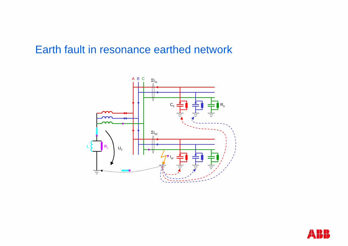
Earth fault in resonance earthed network
A B C
U0
C0
ΣI01
ΣI02
Ief
R0
L RL
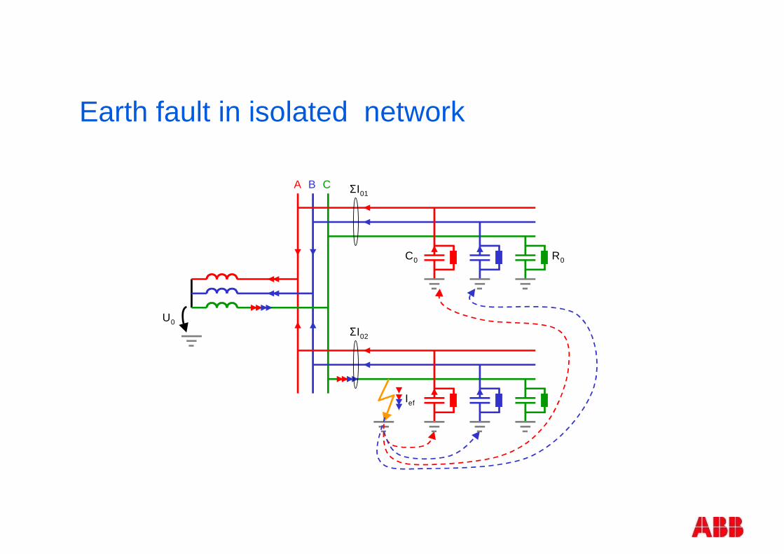
Earth fault in isolated network
A B C
U0
C0
ΣI01
ΣI02
Ief
R0
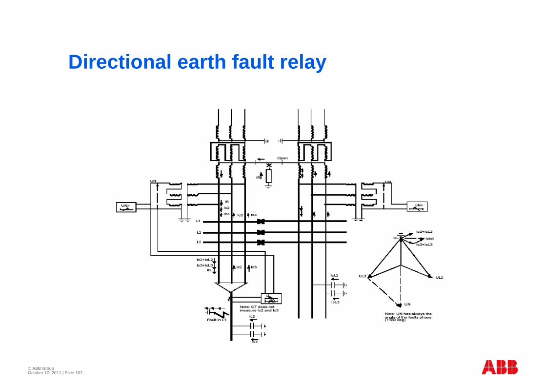
© ABB Group October 10, 2011 | Slide 107
Directional earth fault relay
© ABB Group October 10, 2011 | Slide 108
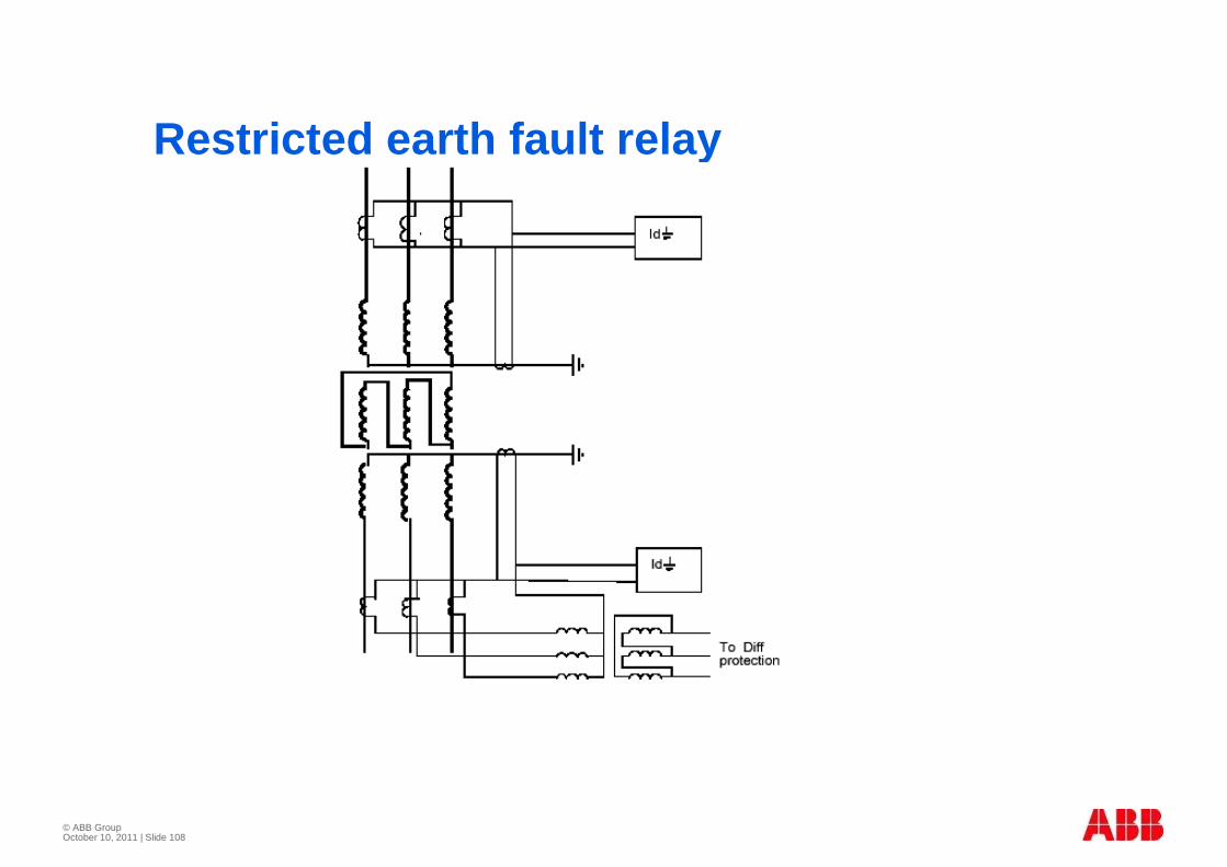
Restricted earth fault relay

© ABB Group October 10, 2011 | Slide 109
© ABB Group October 10, 2011 | Slide 110
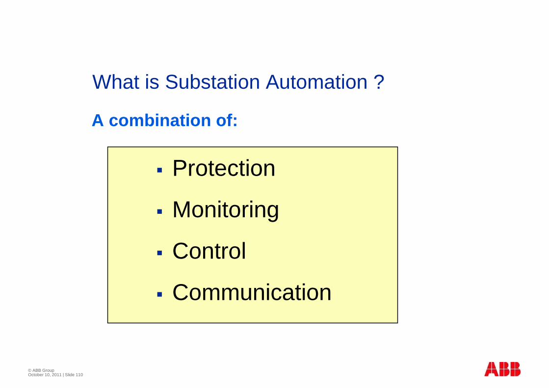
� Protection
� Monitoring
� Control
� Communication
What is Substation Automation ?
A combination of:
© ABB Group October 10, 2011 | Slide 111
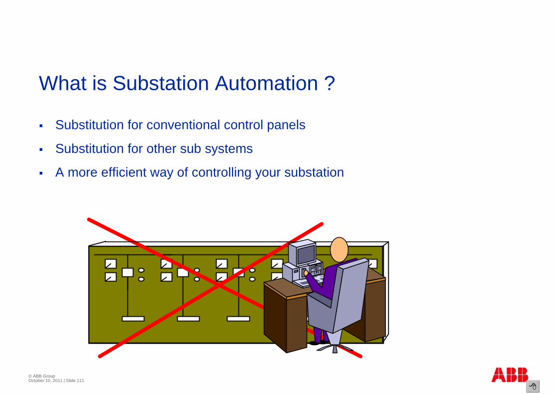
What is Substation Automation ?
� Substitution for conventional control panels
� Substitution for other sub systems
� A more efficient way of controlling your substation
�
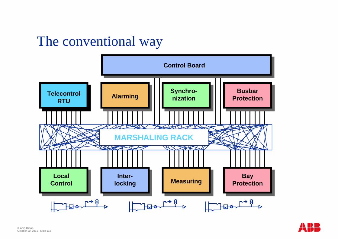
© ABB Group October 10, 2011 | Slide 112
The conventional way
MARSHALING RACK
TELE- ALARMING NISATIONBUSBAR
PROTECTION
LocalControl
Inter-locking Measuring
BayProtection
TelecontrolRTU
AlarmingSynchro-nization
BusbarProtection
Control Board
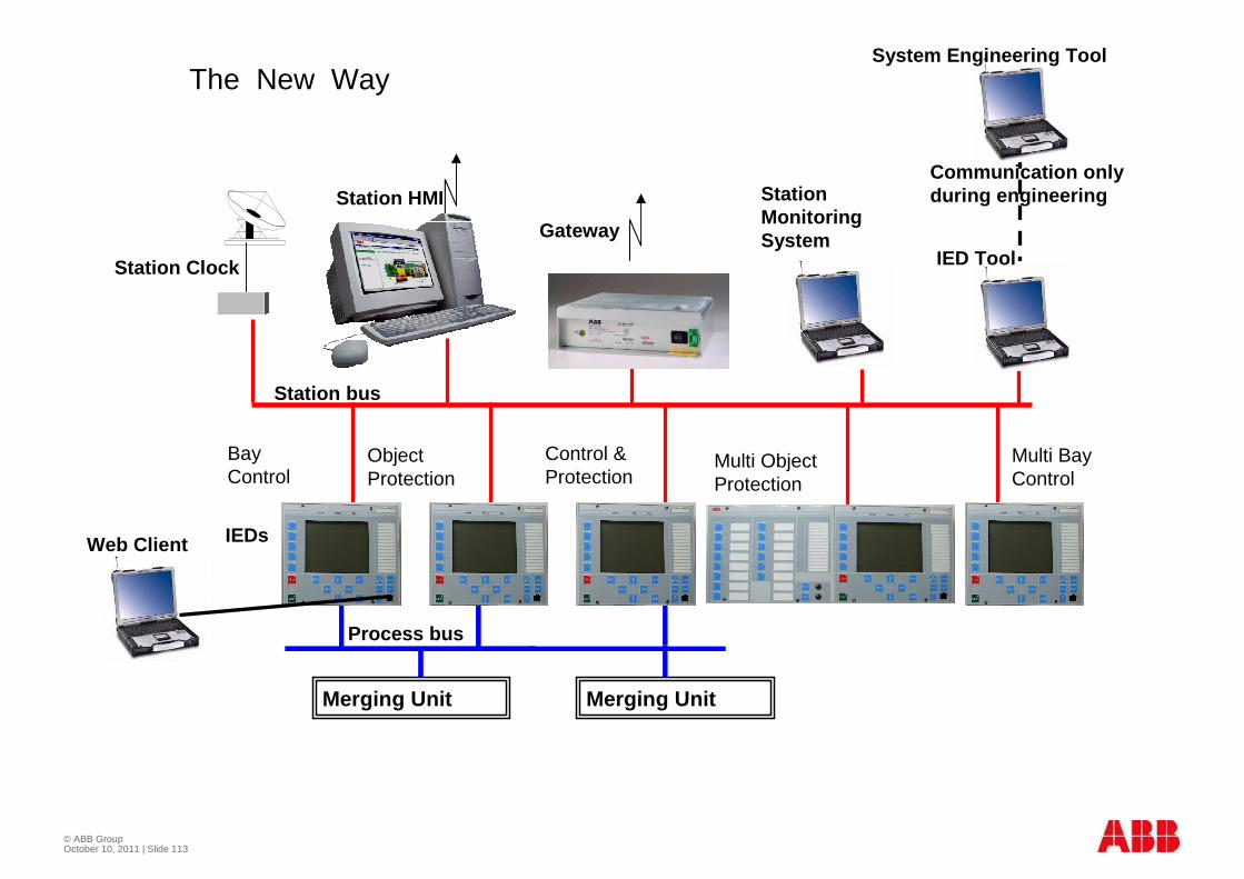
© ABB Group October 10, 2011 | Slide 113
Station HMI
Gateway
Multi ObjectProtection
Merging Unit
Multi BayControl
ObjectProtection
Bay Control
Control &Protection
Merging Unit
IED Tool
System Engineering Tool
IEDsWeb Client
Station Clock
Station bus
Process bus
Communication onlyduring engineeringStation
MonitoringSystem
The New Way

Pro
cess
Lev
elB
ay L
evel
Sta
tion
Leve
l
GIS or AISSwitchgear
-Q1
-Q0 -Q8-Q9
-Q2
1
3
8
=D04+R01225kV LIGNE ABOBO 1ABB
125VDC Distributuion Battery A 125VDC Distributuion Bat te ry B
Fault Recording
Indactic 650 Indactic 650 Indactic 650
=D04+R01225kV LIGNE ABOBO 1ABB
125VDC Distributuion Battery A 125VDC Distributuion Bat te ry B
BAY CONTROL RELAY RE C316*4
1
ABBABB Network Partner
REL316*4
2
4
3
5
6
7
8
9
12
11
13
14
15
16
10
LOCAL CO NTROL METERING
LINE PROTECTION RELAY REL316*4
1
ABBABB Network Partner
REL316*4
2
4
3
5
6
7
8
9
12
11
13
14
15
16
10
BUSBAR PROTECTION REB500
ABBABB Network Partner
REB500
-Q1
=W1
=W2
FERMER
1
2
3
4
5
6
7
8
9
10
11
12
13
14
15
16
cc
Veriosn 4.2b
Bay Protection
LocalControl
=D04+R01225kV LIGNE ABOBO 1ABB
125VDC Distributuion Battery A 125VDC Distributuion Bat te ry B
Busbar ProtectionSCADA
RTU=D04+R01225kV LIGNE ABOBO 1ABB
125VDC Distributuion Battery A 125VDC Distributuion Bat te ry B
RTU 200IN 1 IN 2 IN 3 IN 4 IN 5 IN 6 IN 7 IN 8 OUT
ON/OFF
RTU 200IN 1 IN 2 IN 3 IN 4 IN 5 IN 6 IN 7 IN 8 OUT
ON/OFF
RTU 200IN 1 IN 2 IN 3 IN 4 IN 5 IN 6 IN 7 IN 8 OUT
ON/OFF
=D04+R01225kV LIGNE ABOBO 1ABB
125VDC Distributuion Battery A 125VDC Distributuion Bat te ry B
Indactic650Indactic650
Indactic650
Indactic650
Event Recording
=D04+R01225kV LIGNE ABOBO 1ABB
ABB
-Q2SEL
-Q1SEL
-Q0
SEL
=W1
=W2
FERMEROUVRIR
EXEESC
LAMPETESTE
DISTANCE
LOC
ABB ABB ABB
For each function a dedicated device
and separate Panel Extensive station wide cabling
Extensive bay cabling
Conventional Control & Protection
Marshalling
Control Panel
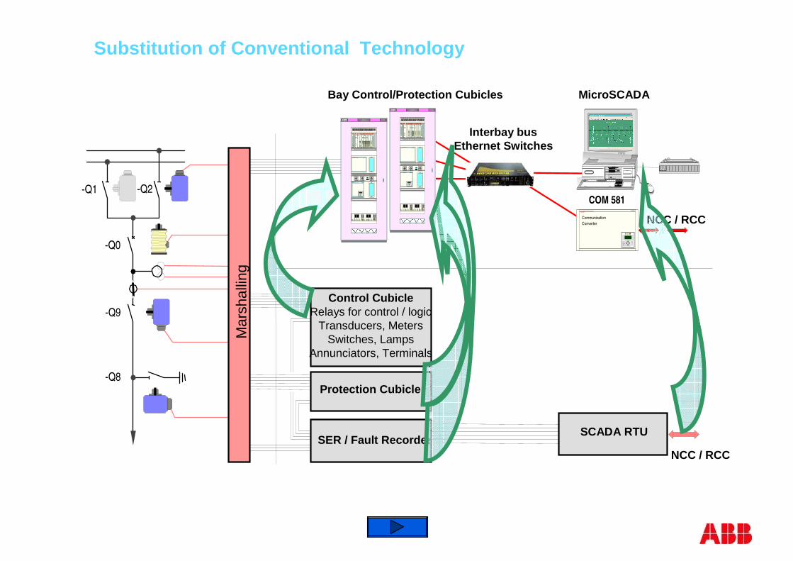
SCADA RTUSER / Fault Recorder
Protection Cubicle
Control CubicleRelays for control / logic
Transducers, MetersSwitches, Lamps
Annunciators, Terminals
Interbay busEthernet Switches
d gi ta l
di gi tal
NCC / RCC
MicroSCADA
ABBPower Automation AG COM581
C
CommunicationConverter
=AD17-KB2Steuerung / SchutzFällanden
Feldsteuergerät REC216 mit Messung und Synchrocheck
LEITUNGSHA UPTSCHUTZ REL316* 4 PRÜFSTECKER
I
0
SCHUTZ EIN/A US
I
0
WE-BLOCK
I
0
STUFENVERL.
Reset
AUS
Bay Control/Protection Cubicles
-Q1
-Q0
-Q8
Mar
shal
ling
-Q9
-Q2
Substitution of Conventional Technology
=AD17-KB2Steuerung / SchutzFällanden
Feldsteuergerät REC216 mit Messung und Synchrocheck
LEITUNGSHA UPTSCHUTZ REL316* 4 PRÜFSTECKER
I
0
SCHUTZ EIN/A US
I
0
WE-BLOCK
I
0
STUFENVERL.
Reset
AUS
COM 581
NCC / RCC

Interbay Bus
ABB Network Partner AG
C
E
COM581
Network ControlCenter NCC
-Q1
-Q0 -Q8-Q9
-Q2
=D04+R01225kV LIGNE ABOBO 1ABB
125VDC Distributuion Battery A 125VDC Distributuion Battery B
BAY CONTROL RELAY REC316*4
1
ABB ABB Networ k Par tner REL316*4
2
43
5678
9
1211
13141516
10
LOCAL CONTROL METERING
LINE PROTECTION RELAY REL316*4
1
ABB ABB Networ k Par tner REL316*4
2
43
5678
9
1211
13141516
10
BUSBAR PROTECTION REB500
ABB ABB Networ k Par tner REB500
ABB
=D04 ABOBO 1
-Q2S E L
-Q1S E L
-Q0S E L
=W1
=W2
FERMEROUVRIR
EXEESC
LAMPETESTE
D I S T A N C E
LOC
ABBP OWE R MONI T ORI NG UNI T
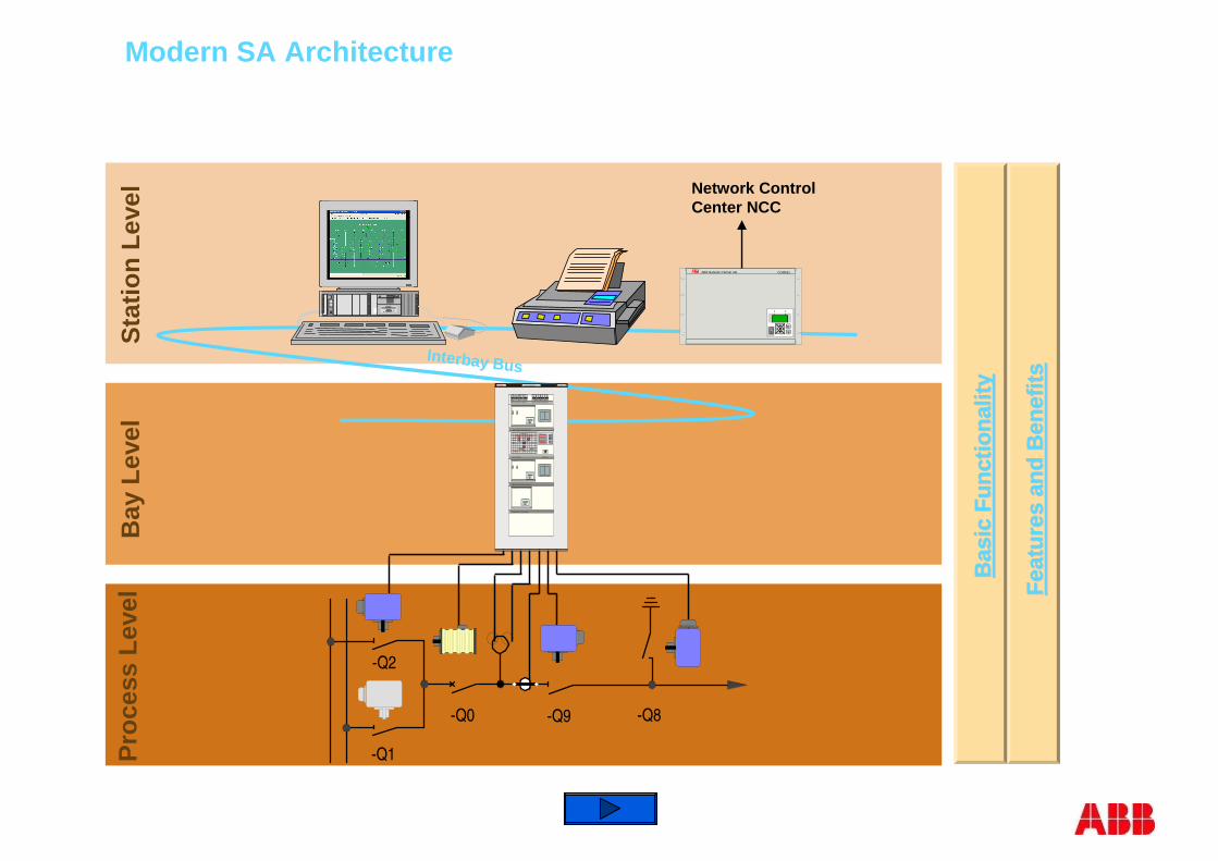
Pro
cess
Lev
elB
ay L
evel
Sta
tion
Leve
l
Fea
ture
s an
d B
enef
itsF
eatu
res
and
Ben
efits
Bas
ic F
unct
iona
lity
Bas
ic F
unct
iona
lity
Modern SA Architecture
t
i i t l
-Q1
-Q0
-Q8
Fee
der
Mar
shal
ling
-Q9
-Q2
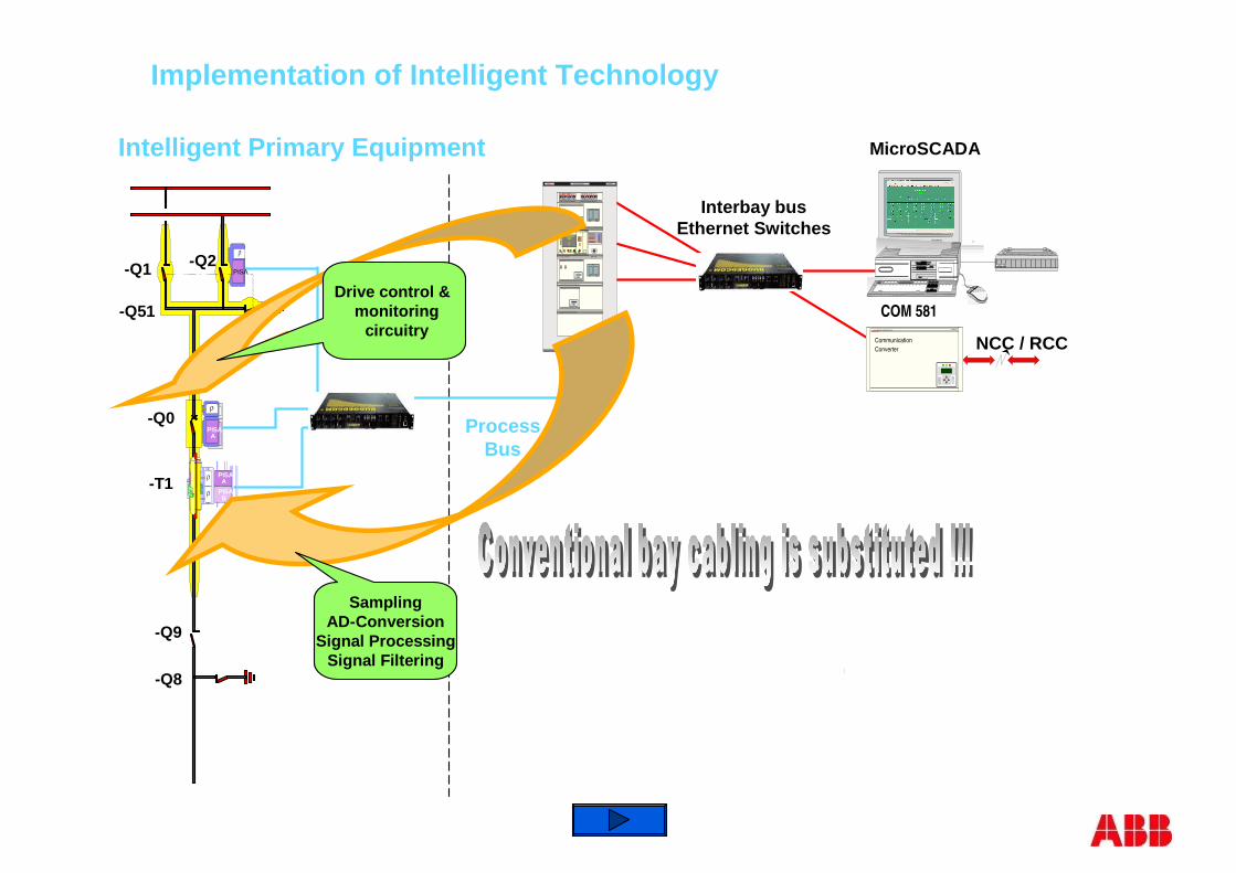
Intelligent Primary Equipment
PISA
PISAA
PISAB
PISA A
-Q1 -Q2
-Q51
-Q0
-T1
-Q9
-Q8
ProcessBus
Interbay busEthernet Switches
d gi tal
di gi tal
NCC / RCC
MicroSCADA
ABBPower Automation AG COM581
C
CommunicationConverter
=D04+R01225kV LIGNE ABOBO 1ABB
125VDC Distributuion Battery A 125VDC Distributuion Battery B
BAY CONTROL RELAY REC316*4
1
ABB ABB Network Par tner REL316*4
2
43
5678
9
1211
13141516
10
LOCAL CONTROL METERING
LINE PROTECTION RELAY REL316*4
1
ABB ABB Network Par tner REL316*4
2
43
5678
9
1211
13141516
10
BUSBAR PROTECTION REB500
ABB ABB Network Par tner REB500
ABB
=D04 ABOBO 1
-Q2S E L
-Q1S E L
-Q0S E L
=W1
=W2
FERMEROUVRIR
EXEESC
LAMPETESTE
D I S T A N C E
LOC
ABBP OWE R MONI T ORI NG UNI T
? LOCAL
REMOTE
SET
OPERATION
M
M
M
Drive control & monitoring
circuitry
SamplingAD-Conversion
Signal ProcessingSignal Filtering
Implementation of Intelligent Technology
COM 581

Process Bus
Interbay Bus
Intelligent SA Architecture
ABB Network Partner AG
C
E
COM581
Network ControlCenter NCC
PIS
A
PIS
AA
PIS
AB
PIS
A
A
-Q1
-Q2
-Q51
-Q0 -T1 -Q9 -Q8
=D04+R01225kV LIGNE ABOBO 1ABB
125VDC Distributuion Battery A 125VDC Distributuion Battery B
BAY CONTROL RELAY REC316*4
1
ABB ABB Network Par tner REL316*4
2
43
5678
9
1211
13141516
10
LOCAL CONTROL METERING
LINE PROTECTION RELAY REL316*4
1
ABB ABB Network Par tner REL316*4
2
43
5678
9
1211
13141516
10
BUSBAR PROTECTION REB500
ABB ABB Network Par tner REB500
ABB
=D04 ABOBO 1
-Q2S E L
-Q1S E L
-Q0S E L
=W1
=W2
FERMEROUVRIR
EXEESC
LAMPETESTE
D I S T A N C E
LOC
ABBP OWE R MONI T ORI NG UNI T
? LOCAL
REMOTE
SET
OPERATION
M
M
M
Pro
cess
Lev
elB
ay L
evel
Sta
tion
Leve
l
Bas
ic F
unct
iona
lity
Bas
ic F
unct
iona
lity
FE
AT
UR
ES
AN
D B
EN
EF
ITS
FE
AT
UR
ES
AN
D B
EN
EF
ITS
Interbay Bus
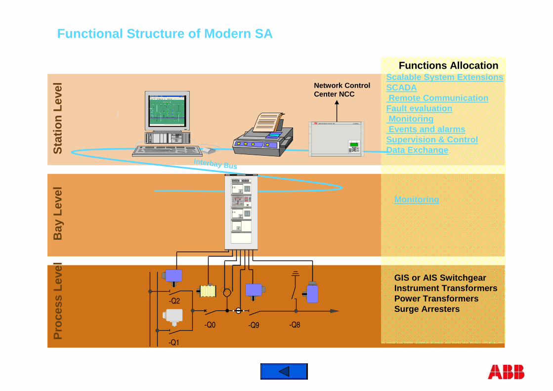
GIS or AIS SwitchgearInstrument TransformersPower TransformersSurge Arresters
-Q1
-Q0 -Q8-Q9
-Q2
Functions Allocation
ABB Network Partner AG
C
E
COM581
Network ControlCenter NCC
=D04+R01225kV LIGNE ABOBO 1ABB
125VDC Distributuion Battery A 125VDC Distributuion Battery B
BAY CONTROL RELAY REC316*4
1
ABB ABB Network Par tner REL316*4
2
43
5678
9
1211
13141516
10
LOCAL CONTROL METERING
LINE PROTECTION RELAY REL316*4
1
ABB ABB Network Par tner REL316*4
2
43
5678
9
1211
13141516
10
BUSBAR PROTECTION REB500
ABB ABB Network Par tner REB500
ABB
=D04 ABOBO 1
-Q2S E L
-Q1S E L
-Q0S E L
=W1
=W2
FERMEROUVRIR
EXEESC
LAMPETESTE
D I S T A N C E
LOC
ABBP OWE R MONI T ORI NG UNI T Monitoring
Scalable System ExtensionsSCADARemote Communication
Fault evaluationMonitoringEvents and alarms
Supervision & ControlData Exchange
Pro
cess
Lev
elB
ay L
evel
Sta
tion
Leve
l
Functional Structure of Modern SA
Interbay Bus
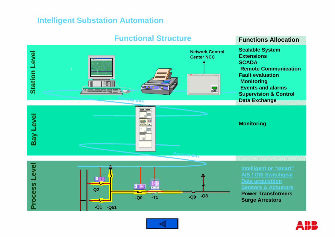
Intelligent or “smart”AIS / GIS SwitchgearData acquisitionSensors & ActuatorsPower TransformersSurge Arrestors
ABB Network Partner AG
C
E
COM581
Network ControlCenter NCC
Process Bus
PIS
A
PIS
AA
PIS
AB
PIS
A
A
-Q1
-Q2
-Q51
-Q0 -T1 -Q9 -Q8
Monitoring
Scalable System ExtensionsSCADARemote Communication
Fault evaluationMonitoringEvents and alarms
Supervision & ControlData Exchange
Functional Structure Functions Allocation
=D04+R01225kV LIGNE ABOBO 1ABB
125VDC Distributuion Battery A 125VDC Distributuion Battery B
BAY CONTROL RELAY REC316*4
1
ABB ABB Network Par tner REL316*4
2
43
5678
9
1211
13141516
10
LOCAL CONTROL METERING
LINE PROTECTION RELAY REL316*4
1
ABB ABB Network Par tner REL316*4
2
43
5678
9
1211
13141516
10
BUSBAR PROTECTION REB500
ABB ABB Network Par tner REB500
ABB
=D04 ABOBO 1
-Q2S E L
-Q1S E L
-Q0S E L
=W1
=W2
FERMEROUVRIR
EXEESC
LAMPETESTE
D I S T A N C E
LOC
ABBP OWE R MONI T ORI NG UNI T
? LOCAL
REMOTE
SET
OPERATION
M
M
M
Pro
cess
Lev
elB
ay L
evel
Sta
tion
Leve
l
Intelligent Substation Automation
ABB
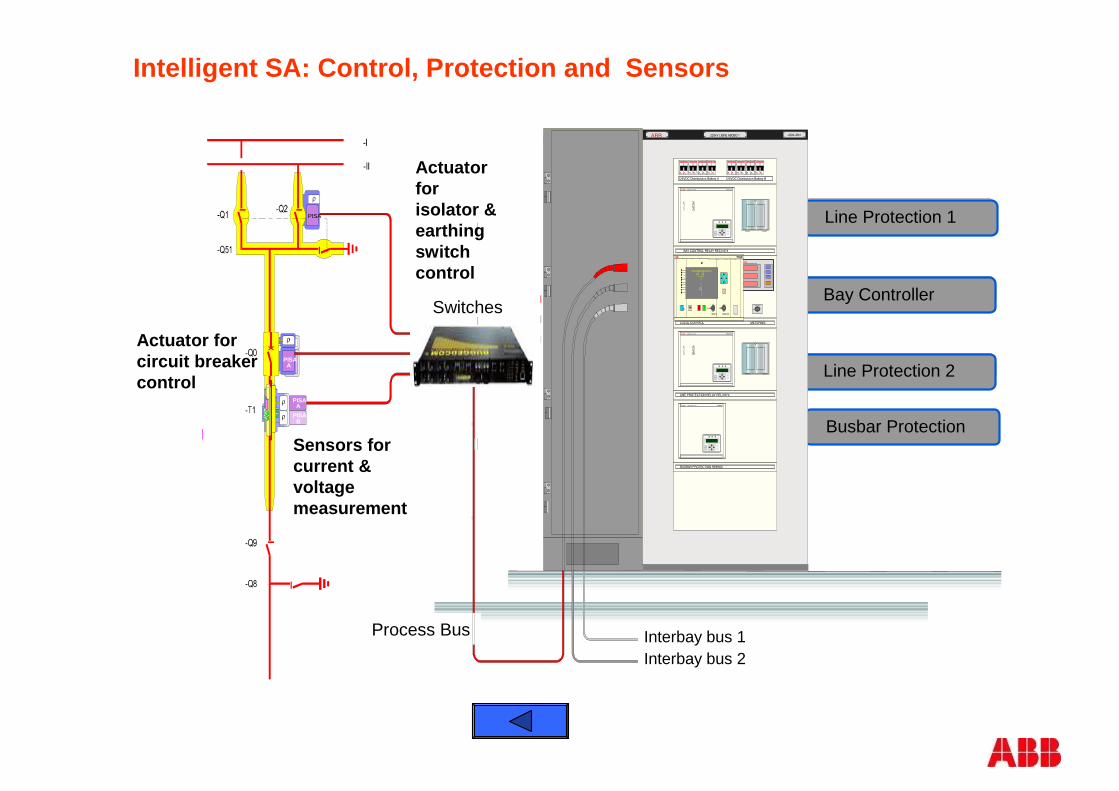
Interbay bus 1Interbay bus 2
PISA
PISA
PISA PISA
PISA A
PISAA
PISAB
Abgangsschutz I
Feldleitgerät
Abgangsschutz II
Line Protection 1
Bay Controller
Line Protection 2
Busbar Protection
Switches
Process Bus
Sensors forcurrent &voltage measurement
Actuator forcircuit breakercontrol
Actuator forisolator & earthingswitch control
Intelligent SA: Control, Protection and Sensors
=D04+R01225kV LIGNE ABOBO 1ABB
125VDC Distributuion Battery A 125VDC Distributuion Battery B
BAY CONTROL RELAY REC316*4
1
ABB ABB Network Partner REL316*4
2
43
5678
9
1211
13141516
10
LOCAL CONTROL METERING
LINE PROTECTION RELAY REL316*4
1
ABB ABB Network Partner REL316*4
2
43
5678
9
1211
13141516
10
BUSBAR PROTECTION REB500
ABB ABB Network Partner REB500
ABB
=D04 ABOBO 1
-Q2SEL
-Q1SEL
-Q0SEL
=W1
=W2
FERMEROUVRIR
EXEESC
LAMPETESTE
DISTANCE
LOC
ABBPOWER MONITORING UNIT
? LOCAL
REMOTE
SET
OPERATION
M
M
M
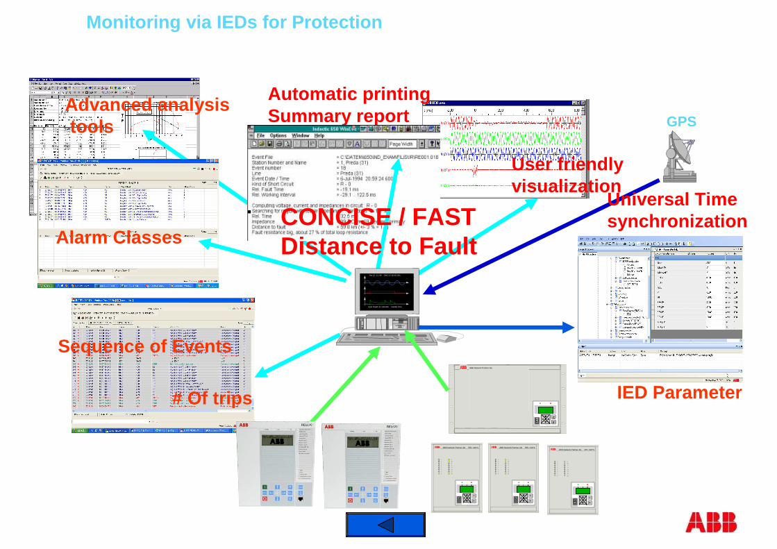
Advanced analysistools GPS
Universal Timesynchronization
User friendlyvisualization
Automatic printingSummary report
CONCISE / FAST Distance to Fault
Monitoring via IEDs for Protection
Alarm Classes
# Of trips
Sequence of EventsABB Network Partner AG
C
E
Mo 12. 11. 96 GMT 17:02.43.305
Ayer Rajah & Labrador Feeder One
1
2
3
4
5
6
7
8
9
10
11
12
13
14
15
16
ABB Network Partner AG REL 316*4
C
E
1
2
3
4
5
6
7
8
9
10
11
12
13
14
15
16
ABB Network Partner AG REL 316*4
C
E
1
2
3
4
5
6
7
8
9
10
11
12
13
14
15
16
ABB Network Partner AG REL 316*4
C
E
IED Parameter
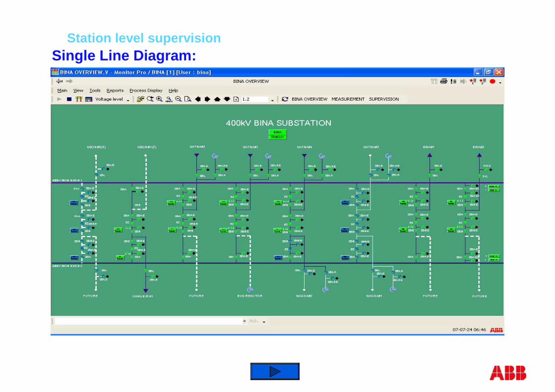
Station level supervisionSingle Line Diagram:

Diagnostic: Fault Recording and Evaluation
Automatic fault location printout
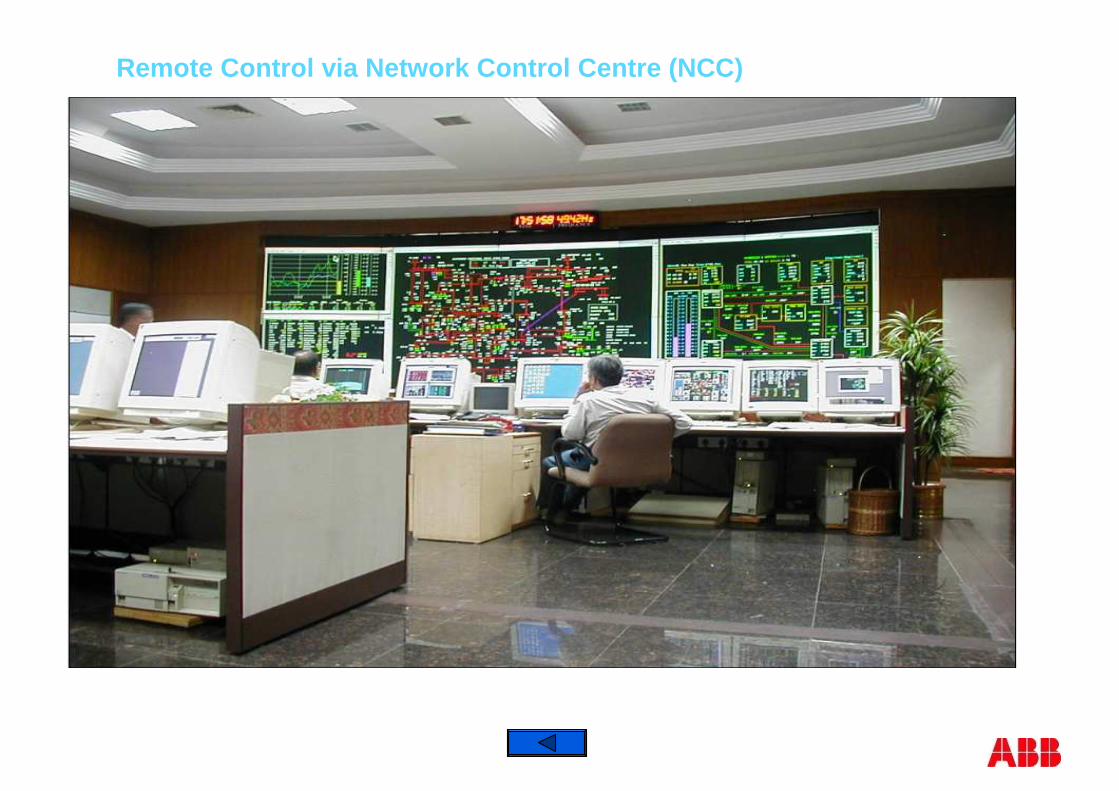
Remote Control via Network Control Centre (NCC)
© ABB Group October 10, 2011 | Slide 127
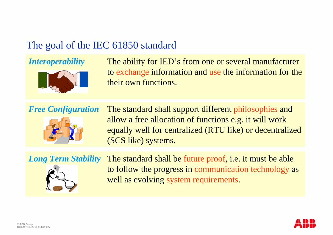
Interoperability The ability for IED’s from one or several manufacturer to exchangeinformation and usethe information for the their own functions.
Long Term Stability The standard shall be future proof, i.e. it must be able to follow the progress in communication technologyas well as evolving system requirements.
Free Configuration The standard shall support different philosophiesand allow a free allocation of functions e.g. it will work equally well for centralized (RTU like) or decentralized (SCS like) systems.
The goal of the IEC 61850 standard

© ABB Group October 10, 2011 | Slide 128