genesis ii select - citywindsor.ca
TRANSCRIPT

Genesis II Select™
User’s Manual &Installation Guide
Canada VariantRevision
16/September/2015
Copyright 2009, 2015 Decatur Electronics, Inc.

Genesis II Select™
User’s Manual &Installation Guide

Genesis II Select™
User’s Manual &Installation Guide
Canada VariantRevision
16/September/2015

Table of Contents
Welcome to Decatur Electronics . . . . . . . . . . . . . . . . . . . . . . . . . . . . . . . . . . . . . . . . . . . 6Genesis II Select™ Features . . . . . . . . . . . . . . . . . . . . . . . . . . . . . . . . . . . . . . . . . . . . 7About This Manual . . . . . . . . . . . . . . . . . . . . . . . . . . . . . . . . . . . . . . . . . . . . . . . . . . . . 8
1 Quick Start . . . . . . . . . . . . . . . . . . . . . . . . . . . . . . . . . . . . . . . . . . . . . . . . . . . . . . . . . . 10
2 Installation . . . . . . . . . . . . . . . . . . . . . . . . . . . . . . . . . . . . . . . . . . . . . . . . . . . . . . . . . . 112 .1 Separating the Computer/Display Unit (Optional) . . . . . . . . . . . . . . . . 112 .2 Mounting and Connecting the Computer/Display Unit . . . . . . . . . . . . 122 .3 Mounting and Connecting the Antenna . . . . . . . . . . . . . . . . . . . . . . . . . . 162 .4 Installation Check . . . . . . . . . . . . . . . . . . . . . . . . . . . . . . . . . . . . . . . . . . . . . . . . 192 .5 VIP™ Installation (Optional) . . . . . . . . . . . . . . . . . . . . . . . . . . . . . . . . . . . . . . . 192 .5 .1 Connecting to the Radar . . . . . . . . . . . . . . . . . . . . . . . . . . . . . . . . . . . . . . . 192 .5 .2 Connecting to the On-Board Diagnostic Port . . . . . . . . . . . . . . . . . . . 202 .5 .3 Connecting to the Video Camera . . . . . . . . . . . . . . . . . . . . . . . . . . . . . . . 202 .5 .4 VIP™ Activation . . . . . . . . . . . . . . . . . . . . . . . . . . . . . . . . . . . . . . . . . . . . . . . . 212 .5 .5 Configuring the VIP™ . . . . . . . . . . . . . . . . . . . . . . . . . . . . . . . . . . . . . . . . . . . 22
3 Computer/Display Unit . . . . . . . . . . . . . . . . . . . . . . . . . . . . . . . . . . . . . . . . . . . . . . . 233 .1 Display Windows . . . . . . . . . . . . . . . . . . . . . . . . . . . . . . . . . . . . . . . . . . . . . . . . . 233 .2 Lights . . . . . . . . . . . . . . . . . . . . . . . . . . . . . . . . . . . . . . . . . . . . . . . . . . . . . . . . . . . 243 .2 .1 Range Lights . . . . . . . . . . . . . . . . . . . . . . . . . . . . . . . . . . . . . . . . . . . . . . . . . . 243 .2 .2 FASTER and SLOWER Lights . . . . . . . . . . . . . . . . . . . . . . . . . . . . . . . . . . . . 243 .2 .2 .1 Moving Mode Same Direction using Non-Directional Antennas 243 .2 .2 .2 Moving Mode Same Direction using Directional Antenna . . . . . . 253 .2 .2 .3 Faster Target . . . . . . . . . . . . . . . . . . . . . . . . . . . . . . . . . . . . . . . . . . . . . . . . . . 253 .2 .2 .4 Fastest Target [OPT] . . . . . . . . . . . . . . . . . . . . . . . . . . . . . . . . . . . . . . . . . . . 26
4 Hand-Held Remote Control . . . . . . . . . . . . . . . . . . . . . . . . . . . . . . . . . . . . . . . . . . . 274 .1 Control Buttons . . . . . . . . . . . . . . . . . . . . . . . . . . . . . . . . . . . . . . . . . . . . . . . . . . 28
5 Communication System Controls . . . . . . . . . . . . . . . . . . . . . . . . . . . . . . . . . . . . . 31
6 Operating the Genesis II Select™ . . . . . . . . . . . . . . . . . . . . . . . . . . . . . . . . . . . . . . 316 .1 Power . . . . . . . . . . . . . . . . . . . . . . . . . . . . . . . . . . . . . . . . . . . . . . . . . . . . . . . . . . . 316 .2 Front and Rear Antenna . . . . . . . . . . . . . . . . . . . . . . . . . . . . . . . . . . . . . . . . . . 316 .3 Stationary Mode . . . . . . . . . . . . . . . . . . . . . . . . . . . . . . . . . . . . . . . . . . . . . . . . . 336 .3 .1 Using Non-Directional Antennas . . . . . . . . . . . . . . . . . . . . . . . . . . . . . . . 336 .3 .2 Using Directional Antennas . . . . . . . . . . . . . . . . . . . . . . . . . . . . . . . . . . . . 346 .4 Moving Mode Opposite Direction . . . . . . . . . . . . . . . . . . . . . . . . . . . . . . . . 38

6 .5 Moving Mode Same Direction . . . . . . . . . . . . . . . . . . . . . . . . . . . . . . . . . . . . 396 .5 .1 Setting Separation Speed . . . . . . . . . . . . . . . . . . . . . . . . . . . . . . . . . . . . . . 416 .6 Faster Mode . . . . . . . . . . . . . . . . . . . . . . . . . . . . . . . . . . . . . . . . . . . . . . . . . . . . . 416 .7 Lock a Speed . . . . . . . . . . . . . . . . . . . . . . . . . . . . . . . . . . . . . . . . . . . . . . . . . . . . 426 .8 Range Setting . . . . . . . . . . . . . . . . . . . . . . . . . . . . . . . . . . . . . . . . . . . . . . . . . . . 436 .9 Stopwatch Mode . . . . . . . . . . . . . . . . . . . . . . . . . . . . . . . . . . . . . . . . . . . . . . . . 43
7 Performance Tips . . . . . . . . . . . . . . . . . . . . . . . . . . . . . . . . . . . . . . . . . . . . . . . . . . . . 457 .1 How Radar Works . . . . . . . . . . . . . . . . . . . . . . . . . . . . . . . . . . . . . . . . . . . . . . . . 457 .2 Interference Sources and Remedies . . . . . . . . . . . . . . . . . . . . . . . . . . . . . . 457 .2 .1 Angular Interference (Cosine Effect) . . . . . . . . . . . . . . . . . . . . . . . . . . . . 467 .2 .2 Fan Interference . . . . . . . . . . . . . . . . . . . . . . . . . . . . . . . . . . . . . . . . . . . . . . . 477 .2 .3 Batching . . . . . . . . . . . . . . . . . . . . . . . . . . . . . . . . . . . . . . . . . . . . . . . . . . . . . . 477 .2 .4 Electromagnetic Interference (EMI) . . . . . . . . . . . . . . . . . . . . . . . . . . . . . 477 .2 .5 Multi-Path Beam Cancellation . . . . . . . . . . . . . . . . . . . . . . . . . . . . . . . . . . 477 .2 .6 Patrol Harmonics . . . . . . . . . . . . . . . . . . . . . . . . . . . . . . . . . . . . . . . . . . . . . . 487 .2 .7 Radio Frequency Interference (RFI) . . . . . . . . . . . . . . . . . . . . . . . . . . . . . 487 .2 .8 Shadowing . . . . . . . . . . . . . . . . . . . . . . . . . . . . . . . . . . . . . . . . . . . . . . . . . . . . 487 .2 .9 Vehicle Ignition Interference) . . . . . . . . . . . . . . . . . . . . . . . . . . . . . . . . . . . 49
8 Field Tests . . . . . . . . . . . . . . . . . . . . . . . . . . . . . . . . . . . . . . . . . . . . . . . . . . . . . . . . . . . . 508 .1 Operator-Requested Self Test . . . . . . . . . . . . . . . . . . . . . . . . . . . . . . . . . . . . . 508 .2 Road Test . . . . . . . . . . . . . . . . . . . . . . . . . . . . . . . . . . . . . . . . . . . . . . . . . . . . . . . . 50
9 Care, Cleaning, and Storage . . . . . . . . . . . . . . . . . . . . . . . . . . . . . . . . . . . . . . . . . . 52
10 Specifications . . . . . . . . . . . . . . . . . . . . . . . . . . . . . . . . . . . . . . . . . . . . . . . . . . . . . . . . 5310 .1 Mechanical . . . . . . . . . . . . . . . . . . . . . . . . . . . . . . . . . . . . . . . . . . . . . . . . . . . . . 5310 .2 Antenna . . . . . . . . . . . . . . . . . . . . . . . . . . . . . . . . . . . . . . . . . . . . . . . . . . . . . . . . 5310 .3 Environment . . . . . . . . . . . . . . . . . . . . . . . . . . . . . . . . . . . . . . . . . . . . . . . . . . . . 5410 .4 Power Consumption . . . . . . . . . . . . . . . . . . . . . . . . . . . . . . . . . . . . . . . . . . . . 5410 .5 Accuracy . . . . . . . . . . . . . . . . . . . . . . . . . . . . . . . . . . . . . . . . . . . . . . . . . . . . . . . 5510 .6 Speed Range . . . . . . . . . . . . . . . . . . . . . . . . . . . . . . . . . . . . . . . . . . . . . . . . . . . 55
11 Legal Requirements . . . . . . . . . . . . . . . . . . . . . . . . . . . . . . . . . . . . . . . . . . . . . . . . . . 56
12 Frequently Asked Questions (FAQ) . . . . . . . . . . . . . . . . . . . . . . . . . . . . . . . . . . . . 62
13 Service . . . . . . . . . . . . . . . . . . . . . . . . . . . . . . . . . . . . . . . . . . . . . . . . . . . . . . . . . . . . . 63
14 How to Order Additional Products . . . . . . . . . . . . . . . . . . . . . . . . . . . . . . . . . . . . 65
Appendix A - Communications Port . . . . . . . . . . . . . . . . . . . . . . . . . . . . . . . . . . . . . . . 67
USER NOTES . . . . . . . . . . . . . . . . . . . . . . . . . . . . . . . . . . . . . . . . . . . . . . . . . . . . . . . . . . . . . . 68

Gen
esis II Select™ U
ser’s & Installation M
anual
16/September/20156
Welcome to Decatur Electronics, Inc.
Thank you for choosing the Decatur Electronics Genesis II Select™ — A highly advanced traffic radar unit that will reward your department with years of dependable service . The Genesis II Select™ design incorporates high performance and long range, with many leading features . We urge you to study this manual before using the Genesis II Select™, so you can maximize the benefits of this sophisticated radar device . We believe you will be pleasantly surprised by the features and advantages .
The Genesis II Select™ is small, dependable, features instant target acquisition . If you are as pleased with its performance as we think you will be, ask your Decatur sales representative about other Decatur products including the Genesis™ line of radars, the Onsite™ line of speed trailers, dollies, and pole signs and the Responder™ line of in-car video systems .
Traffic officers told us exactly what they wanted in a radar device - and we built it . Try any one of our products and see if you don't agree that it is the best-in-class!
—The Management and Staff at Decatur Electronics,

Gen
esis II Select™ U
ser’s & Installation M
anual
16/September/20157
Genesis II Select™ FeaturesThe Genesis II Select™ is a highly advanced traffic radar device offering many advanced capabilities . It includes 32-bit digital signal processing (DSP), a versatile detachable computer/display unit, a variety of interchangeable antennas, and an easy-to-use hand-held remote control . It also features Faster Mode for detecting the next strongest target going faster than the strongest in multiple target situations .
The Genesis II Select's™ digital signal processing (DSP) provides instant target acquisition and speed lock as well as more precise tracking and speed measurement .
If space in your motor vehicle is at a premium, you will appreciate the detachable computer/display unit . For more safety conscious installation options, you can separate the pieces and mount them wherever best meets your specific needs .
The Genesis II Select™ interchangeable antennas lets you choose a combination that is right for you . For example, you can transmit from K-band, K-band Directional and Ka-band silver ring antennas . When used with K-band Directional antennas the Genesis II Select™ is able to determine which direction targets are moving . Directional technology enables the radar to single out motor vehicles moving in one specific direction, while ignoring motor vehicles moving in the other direction . This capability makes stationary operation far more effective and makes moving same direction mode very easy to operate .
The hand-held remote controls all of the functions of the radar unit . The remote features convenient “eyes-off” raised buttons for use without taking your eyes off the road and fits comfortably in the palm of your hand, positioning all controls at your fingertips .

Gen
esis II Select™ U
ser’s & Installation M
anual
16/September/20158
About This ManualThis manual contains valuable information to help you set up, use and maintain your Genesis II Select™, so you can optimize its life and keep it at peak performance . Please take a moment to read through it, and keep it handy for future reference .
Note the following symbols in this manual:
Indicates a warning message about safety precautions . Please read it carefully .
Indicates a helpful tip or precaution to note .
Indicates section refers to optional equipment .[OPT]

Gen
esis II Select™ U
ser’s & Installation M
anual
16/September/20159
Your Genesis II Select™ radar unit includes selections from the following components:
Detachable Computer/Display Unit
Handheld Remote
K and Ka Band Antennas Various Connector Cables
Optional VIP Various Mounting Brackets
Optional Radar Mirror Display

Gen
esis II Select™ U
ser’s & Installation M
anual
16/September/201510
1. Quick StartUse the following instructions to quick start your Genesis II Select™:
1 . With all cables, antennas and the hand remote attached, plug the cigar plug of the radar into a powered 12VDC cigarette lighter receptacle in the patrol motor vehicle .
2 . Press the PWR button on the hand-held remote to power up the radar unit . The radar will run through a brief self-test .
3 . Press the ANT FRONT or REAR button to select the antenna from which you want the radar to transmit . Press the same ANT button when you wish to place the radar back into standby mode .
4 . Press and release the MODE button to quickly toggle between Moving Mode Opposite Direction and Moving Mode Same Direction . Press and hold the MODE button for two seconds to activate Stationary Mode .
5 . Press and hold the FAST button to select Faster Mode when you want to track the next strongest target going faster than the strongest .
6 . If you are in the Moving Mode Same Direction setting and are using non-directional antennas and want to track a target that is traveling slower than the patrol motor vehicle, press and release the FAST button for Slower Mode . (Directional antennas automatically select the correct setting for you .)
7 . To lock on a target speed, press the LOCK button . The target speed will transfer to the LOCKED window . The radar will continue to process speeds and display them in the TARGET window .
8 . To clear a locked speed, press the LOCK button when an antenna is transmitting and no target is present .
• Theonlyfunctionthatcanbecompletedwithoutlosingthe locked speed is activating the test function .

Gen
esis II Select™ U
ser’s & Installation M
anual
16/September/201511
2. InstallationUse the following instructions to mount your Genesis II Select™:
2.1 Separating the Computer/Display Unit (optional)If the space in your motor vehicle is at a premium, you will appreciate Genesis II Select’s™ compact size and versatile components . You can separate and remotely mount the computer unit from the display unit . Common places to mount it are behind the dash, under the driver’s seat, or on the console .
To separate the combined unit, firmly grasp the ends and pull them apart .
Figure 2.1a Separating the computer/display unit .
Note the 9-pin connectors on each half of the unit . Screw two standoffs into the holes next to each connector to attach the two pieces with the 9-pin connector cable .
Figure 2.1bTo connect the separated unit, first insert the
standoffs to secure the cable connectors .

Gen
esis II Select™ U
ser’s & Installation M
anual
16/September/201512
Then attach and secure the connectors with the thumbscrews on the sides of each cable connector .
Figure 2.1cSecure the connecting cable by fastening the
thumbscrews into the standoffs .
To return the unit to a one-piece configuration, remove the cables and standoffs, line up the 9-pin connectors, and push the two pieces together .
2.2 Mounting and Connecting the Computer/Display Unit
WARNINGS
• DonotplacetheGenesisIISelect™componentsinlocations that will obscure the driver’s view of the road .
• Double-checkeachcomponenttoensureitissecurelymounted . In an accident, a loose component could strike an occupant of the vehicle .
• DonotplacetheGenesisIISelect™computer,antennas,cables, or brackets in your vehicle’s air bag deployment zones . Refer to your vehicle’s owner’s manual or call the vehicle manufacturer if you are unsure where the air bag deployment zones are .

Gen
esis II Select™ U
ser’s & Installation M
anual
16/September/201513
You can mount the computer/display unit behind and to the side of the steering wheel or on the dashboard . The computer unit easily withstands and remains accurate in temperature extremes . Dash-mounting the unit promotes safety; you can read the display without taking your eyes off the road .
To mount the unit, use the Velcro™ fastening material or the mounting bracket . Before applying the Velcro™, use a clean cloth to remove any foreign material from the dashboard and bracket face . Position the Velcro™ lightly on the computer/display unit and mounting surface .
After the unit is in the correct position, press it firmly to affix it to the surface . For the bracket mount, simply place and tighten the screws on the mounting bracket into the holes in the unit . Then adhere the suction cups to a clean glass surface . For maximum adhesion, moisten the suction cups before affixing them to the surface .
There are five locations where cables connect to the rear panel of the computer unit . Four are quick-disconnect connectors, and a fifth is a nine pin DB-9 connector . The color coded circle around each of the quick-disconnect connectors corresponds to a color band on the cable that connects to them .
Figure 2.2aThe quick-disconnect connectors plug intothe computer unit in the above locations .

Gen
esis II Select™ U
ser’s & Installation M
anual
16/September/201514
1 . Align the red dot on the connector with the red dot at the top of the receptacle .
2 . Push the connector into the receptacle until you hear a click .
Figure 2.2bAlign the red dot on the connector with the red
dot on the computer receptacle .
Power connector
WARNING
• Besuretoplugtheconnectorintothecomputerunitfirst before plugging the power plug into the auxiliary power source . If the power source is on, it can damage the unit .
The power cable has a larger 12-volt power plug (cigar plug) on one end . Make sure the plug fits securely in the motor vehicle’s auxiliary power (cigarette lighter) receptacle .
Figure 2.2cThe cigar plug for the auxiliary power receptacle .

Gen
esis II Select™ U
ser’s & Installation M
anual
16/September/201515
Remote connectorThe hand-held remote has two connectors, one that plugs into the remote and one that connects to the back of the computer unit . While both connectors are the same, the connector with the strain relief boot typically connects to the hand-held remote .
Figure 2.2dCable connector that plugs into the
computer unit has no boot .
Antenna connectorThe antenna cable uses two different connectors . One connector plugs into the antenna and has a more smooth finish than the connector that plug into the unit . It is important that the right connector be plugged into the right receptacle or damage to the connector or receptacle may result .
Figure 2.2eCable connector that plugs into the antenna .
To remove a cable, grasp and pull the connector .
Serial connectorOn the back of the computer unit there is a female DB-9 connector marked “serial” that allows you to connect the Genesis II Select™ to other devices (i .e . display signs, in-car video, PCs) . To use this RS232 serial connector you will need a communications cable . (A communications cable for video and PC is not included . You can order it from Decatur Electronics by calling 800 .428 .4315 or by contacting your authorized dealer .)

Gen
esis II Select™ U
ser’s & Installation M
anual
16/September/201516
2.3 Mounting and Connecting the AntennaThree different antenna types are available for the Genesis II Select™ : K-band, K-band Directional, and Ka-band silver ring . These antennas are incredibly strong, yet compact and lightweight . The antennas are interchangeable, so you can configure your radar unit with a second antenna of the same or different band without changing the hardware, software, and controls .
Figure 2.3aAntennas for the Genesis II Select™ include
K-band/K-band Directional (left) and Ka-band silver ring (right) .
A variety of brackets are available to mount the antennas . To attach the antennas to the standard brackets, align the threaded mounting hole on the antenna with the threaded post of the front antenna bracket and on the rear antenna bracket the threaded knob with the slot on the L-brace . Then screw the post or knob into the threaded mounting hole . Examples are shown in Figures 2 .3b and 2 .3c .
Figure 2.3cA rear mount antenna (K-band)
using the S758-34-0 bracket
Figure 2.3bA front mount antenna (Ka-band)
using the S773-235A-0 bracket

Gen
esis II Select™ U
ser’s & Installation M
anual
16/September/201517
Front Antenna MountingWhen mounting the front antenna bracket to the windshield use the following bullet points to help in determining the proper location .
• MakesurethatyouDo Not mount the antenna in the deployment path of the air bag or where it will obstruct the driver's vision .
• Gluethebuttoninalocationsothattheantennawillbecompletely below the tinted area of the windshield as shown in Figure 2 .3d .
• Priortogluingthebuttoninplace,testthepotentialantennalocation for good performance and for any fan interference .
Once the considerations listed above have been observed, follow the instructions on the glue packet making sure that the windshield glass is properly cleaned and prepared . Apply the glue to the button, as described in the glue packet instructions . Make sure that the button's orientation is correct (do not glue the button on upside down) . Hold the button in place for the length of time outlined in the instructions . Allow the glue to fully cure before mounting the bracket and antenna to the button .
Figure 2.3dProper antenna mounting .

Gen
esis II Select™ U
ser’s & Installation M
anual
16/September/201518
Antenna AlignmentAfter you affix the bracket, adjust the position of the antenna . ANY SIGNIFICANT DEVIATION FROM A PARALLEL ORIENTATION CAN AFFECT THE RADAR’S READING DUE TO THE COSINE EFFECT .
Figure 2.3eCorrect Orientation
The antenna is parallel to the targetvehicle's direction .
Figure 2.3fIncorrect Orientation
The antenna and target vehicle'sdirection are not parallel .
Point the antenna so it is parallel with the patrol motor vehicle, (the direction the patrol motor vehicle is facing) and parallel with the ground . Avoid setting the antenna at an angle since the reading displayed can be affected due to the angle .
Rear Antenna MountingMount the rear-facing antenna so it has a clear view of traffic and so it is not obstructing the driver's view . The bracket is easily affixed to the rear deck using the Velcro™ strips supplied with the bracket . Follow the same orientation instructions as for the front antenna .
• Useonlythemountinghardwareapprovedbyyouragency . Damage to the antenna housing can occur if you use incorrect fasteners .
• Donotmodifythebrackets.Mostbracketsincorporatean isolator that prevents the metal housing of the antenna from coming into contact with the frame of the car . Removal of the isolator can cause interference to be easily picked up diminishing performance .
• Whenremovingbracketsthathavesuctioncups,usethe tabs on the suction cups to break the vacuum seal .

Gen
esis II Select™ U
ser’s & Installation M
anual
16/September/201519
After you have mounted the antenna, plug the cable into the antenna and the antenna receptacle on the computer/display unit . If you are using only one antenna, you must connect it to the FRONT antenna receptacle . Either the FRONT or REAR button on the remote can activate a single antenna system .
2.4 Installation Check After you install the components, for safety, double-check to ensure all components are secure .
2.5 VIP Installation (Optional)If your Genesis II Select has come with the optional Motor vehicle Interface Portal™ (VIP™) then use the following installation instructions .
WARNING • BeforeconnectingtheVIP™,ensurealldevices,
including the motor vehicle and radar are powered off .
2.5.1 Connecting to the RadarConnect the VIP's™ communications cable to the Genesis II Select's™ communication port located on the back panel of the radar unit . This port is a DB-9 female connector labeled “SERIAL” . Refer to the picture in Figure 2 .5 .1 .
Figure 2.5.1VIP connection to Radar

Gen
esis II Select™ U
ser’s & Installation M
anual
16/September/201520
2.5.2 Connecting to the On-Board Diagnostic PortConnect the VIP™ to the motor vehicle’s On Board Diagnostics port . (Refer to your owner’s manual for the location of your motor vehicle's OBD-II port .)
In some motor vehicles the clearance between where the diagnostics port is located and the bottom of the dash is very close and can cause the port and VIP™ to be bumped by the officer’s leg when getting into the motor vehicle . In those cases Decatur offers a two-foot right angle extension cable (S769-15) to allow the VIP™ to be relocated away from the port so as not to be damaged . Contact Decatur Electronic’s Customer Service Department at 800 .428 .4315 for ordering information or contact your authorized dealer .
2.5.3 Connecting to the Video CameraThe VIP™ has an additional cable that supports the video overlay feature . Plug the VIP's™ overlay cable into the video camera port labeled “RADAR” on your Gemini™ , Shadow™, or Responder 1000™ video camera . Refer to Figure 2 .5 .3 .
Figure 2.5.3VIP connection to Video Camera

Gen
esis II Select™ U
ser’s & Installation M
anual
16/September/201521
2.5.4 VIP™ ActivationBefore activating the VIP™ it is recommended that you read the section on Operating the Genesis II Select™ .
The patrol motor vehicle must be running, simply having the key turned to auxiliary is not enough to fully activate the VIP™ . Make sure the LED light on the VIP™ is constantly on .
The VIP™ does not have to be plugged into the Genesis II Select™ for you to note the LED status .
• Itmaytakeupto4minutesfortheVIP™tostartcommunicating with certain motor vehicles, although most only take a few seconds .
• IftheLEDisflashing,thereareerrorsinthedatabeingsent from the car .
• DonotexposetheVIP™toexcessivemoistureorsubmerge the VIP™ .
• IftheLEDismostlyoffbutflickersonlyoccasionallythere is an issue with the power being supplied to the VIP™ . The VIP™ is in hibernation mode to conserve the motor vehicle's battery .
If the LED is on and the VIP™ is connected to a radar unit, then when the radar is turned on and it runs through its diagnostics routine it will show the message “VIP” as the last message on power up .
Once the power-up routine has run correctly and the VIP™ message has been displayed, the next step is to make sure the Genesis computer is configured properly . To do this have the motor vehicle running, but stopped . With the VIP™ properly installed try to put the radar into moving mode . The VIP™ should note that the motor vehicle is stopped and automatically switch the radar to stationary mode .

Gen
esis II Select™ U
ser’s & Installation M
anual
16/September/201522
• Ifyourradardoesnotautomaticallyswitchtostationarymode when stopped, please check the menu feature setup on the radar and make sure the VIP™ has been activated .
The next step will walk you through setting up the VIP™ if it is not being recognized by the radar . You can also refer to the menu feature set up in the radar’s operator manual .
2.5.5 Configuring the VIP™ To get the Genesis II Select™ to recognize that the VIP™ has been connected it may be necessary to go into the radar’s menu feature and select the VIP™ .
1 . With the radar turned on and all power-up routines having been ran, press and HOLD the Test button on the hand remote until the word MENU is displayed on the radar . Then release the test button .
2 . Next, press the OPTN button several times until VIP™ is displayed .
3 . Press the UP arrow (front antenna) button and make sure the word AUTO is showing in the display .
4 . Press the Test button again to exit the menu and save the setting .
The mode window will display “EXIT” and the radar will return to normal operation . The VIP™ is now configured to the radar .

Gen
esis II Select™ U
ser’s & Installation M
anual
16/September/201523
3. Computer/Display UnitThe Genesis II Select™ faceplate contains four windows for displaying the patrol, target, locked target speeds and mode . In addition, the faceplate also has indicators used to show the range setting, faster or slower setting and whether the front or rear antenna has been selected .
Figure 3aThe Genesis II Select™ front display .
The faceplate also contains a photocell that automatically dims the display at night for less glare and makes the display brighter in daylight conditions, so you can easily read the display windows .
Figure 3bThe Genesis II Select™ rear interface
3.1 Display WindowsTARGET: Displays target speeds and is blank when no target is present .
MODE: Displays the mode of operation (Stationary, Moving Mode Opposite Direction, or Moving Mode Same Direction) except during power up, self-test or when an error occurs . When an error occurs, one of the following appears in the MODE window:

Gen
esis II Select™ U
ser’s & Installation M
anual
16/September/201524
• LowV lowvoltage
• RFI radiofrequencyinterference
• SYS systemfailure
• RMT? disconnectedhand-heldremote
LOCKED: When you press the LOCK button, the LOCKED window holds and displays the target speed that was in the TARGET window .
PATROL: Displays the patrol speed . The window is blank when the radar unit is in Stationary Mode or when the motor vehicle is traveling below the minimum patrol speed .
3.2 Lights3.2.1 RANGE Lights
Indicates the sensitivity setting (or the target-acquisition distance) . The range can be independently set for each main operating mode .
Figure 3.2aShort Range
Figure 3.2bMedium Range
Figure 3.2cMaximum Range
3.2.2 FASTER and SLOWER Lights The FASTER and SLOWER lights are used to indicate different settings depending on the mode of operation and what features are activated .
3.2.2.1 Moving Mode Same Direction using Non-Directional Antennas
SLOWER: When using non-directional antennas in the Moving Mode Same Direction pressing the FAST button will toggle between the Faster and Slower lights under the Mode window . When a target vehicle is moving slower than the patrol vehicle press the FAST button so the Slower light illuminates .

Gen
esis II Select™ U
ser’s & Installation M
anual
16/September/201525
FASTER: When a target motor vehicle is moving faster than the patrol motor vehicle press the FAST button so the Faster light illuminates .
Figure 3.2.2.1The Faster light
3.2.2.2 Moving Mode Same Direction using Directional AntennasWhen using directional antennas in the same direction mode once the directional antenna has been selected the FASTER and SLOWER lights will go out and pressing the FAST button will no longer be used to select FASTER or SLOWER since the selection will be made by the radar . However, if your radar is equipped with the Fastest Target feature then pressing the FAST button will active that feature . (See Section 3 .2 .2 .4)
3.2.2.3 Faster TargetFASTER: When in Stationary or Moving Mode Opposite Direction and using either directional or non-directional antennas, press and hold the FAST button to activate the Faster Mode . The FASTER light will illuminate and the TARGET window will display the speed of the next strongest target going faster than the strongest target . (Pressing the LOCK button will place the displayed speed into the LOCKED window .) The unit will remain in Faster mode for 2 seconds . After that it exits Faster mode and the FASTER light goes out .

Gen
esis II Select™ U
ser’s & Installation M
anual
16/September/201526
3.2.2.4 Fastest Target [OPT]A variation of the Faster Target is available as an option . This option works the same as the Faster Target feature except the unit stays in FASTER Mode until the FAST button is pressed again . In other words, if your unit is equipped with this option then the FASTER light will remain illuminated when the FASTER button is pressed and the strongest target speed will be displayed in the TARGET window and the LOCKED window will display the speed of the next strongest target going faster than the strongest target . Pressing the FASTER button again will return the unit to normal operation and the FASTER light will shut off . (The SLOWER light is not used .)
Figure 3.2.2.4aThe Faster light
ANT FRONT and REAR: Indicates which antenna is transmitting . In standby mode, neither light is on and neither antenna is transmitting .
Figure 3.2.2.4bAntenna lights showing front antenna is active
Gen
esis II Select™ U
ser’s & Installation M
anual
16/September/201527
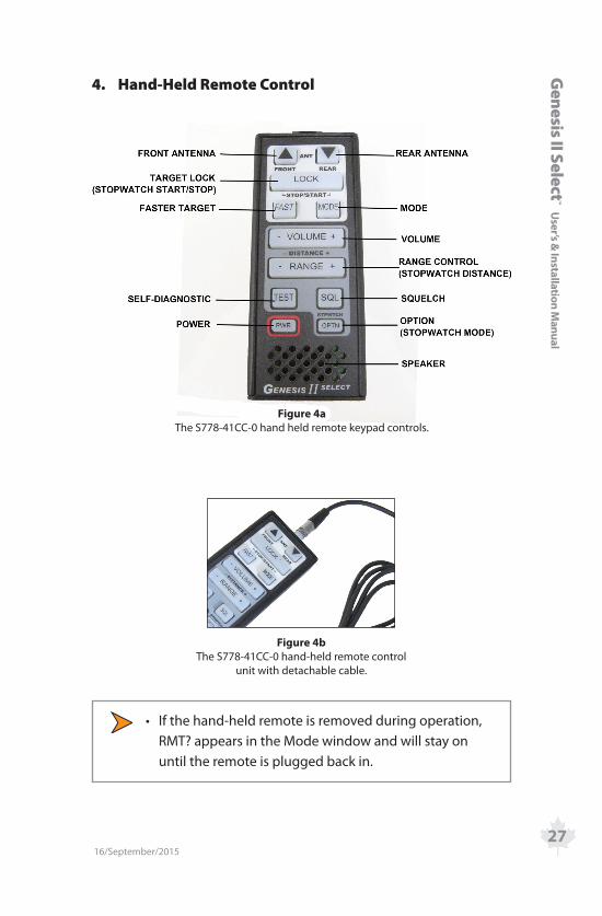
4. Hand-Held Remote Control
Figure 4aThe S778-41CC-0 hand held remote keypad controls .
Figure 4bThe S778-41CC-0 hand-held remote control
unit with detachable cable .
• Ifthehand-heldremoteisremovedduringoperation, RMT?appearsintheModewindowandwillstayon until the remote is plugged back in .

Gen
esis II Select™ U
ser’s & Installation M
anual
16/September/201528
4.1 Control ButtonsPOWER (PWR): powers the Genesis II Select™ on and off .
OPTION (OPTN): The City/Highway option helps reduce shadowing by setting a different minimum patrol speed for city and highway speed conditions . This option works only while the unit is set in a Moving Mode and the motor vehicle is not equipped with a VIP .
STOPWATCH MODE [OPT]: To place the Genesis II Select™ into the Stopwatch operational mode, press and hold the OPTN button for two seconds . The letters StpW will appear in the MODE window . Press the OPTN button again to exit this mode . See Section 6 .9 for a full description of the Stopwatch Mode .
PATROL SPEED LOCK, RECALL and BLANKING [OPT]: This feature comes standard with the Genesis II Select™ and will enable the patrol officer to lock a target speed which will then become displayed in the locked window, while remembering internally what the patrol speed was at the time the speed was locked . The Genesis II Select™ will, as long as the antenna remains activated, continue to track both the speed of the target in the target window and the patrol motor vehicle speed in the patrol window .
1 . To blank the patrol speed, press the OPTN button . Then press the OPTN button again to recall it .
2 . To permanently remove the locked patrol speed, reactivate the antenna by turning it on .
TEST (TEST): Pressing the TEST button starts an extensive self test of the radar unit’s circuitry . During self test, the system will not power down until the test is complete . If the self test fails, the SYS message will appear in the MODE window . For more information on tests, see Section 8: Field Tests .
Pressing and holding the test button activates the menu feature . This feature allows the operator to adjust some of the settings of the radar . See MENU FEATURE .

Gen
esis II Select™ U
ser’s & Installation M
anual
16/September/201529
SQUELCH (SQL): Selects the type of Doppler audio you hear . In squelch mode, the sound is only the Doppler tone for the currently displayed target . In the unsquelched mode, the unit sends out all Doppler tones received by the antenna—patrol motor vehicles, targets, interference, and noise . You typically use unsquelched audio when you listen for interference .
RANGE (– RANGE +): Regulates the maximum target-acquisition distance . You press the negative (–) or positive (+) side of the RANGE button to decrease and increase the target acquisition distance . When in the Stopwatch Mode, the RANGE button cycles through distance units .
VOLUME (– VOLUME +): The volume control regulates the Doppler audio and system status tone (beep) volume . Press the negative (–) or positive (+) side of the VOLUME button to decrease and increase the volume level .
FAST (FAST): Controls the Faster Mode feature .
MODE (MODE): Switches between the three operating modes: Stationary Mode, Moving Mode Opposite Direction, and Moving Mode Same Direction .
LOCK (LOCK): Transfers the target speed in the TARGET window to the LOCKED window . After locking the speed, the system continues to process and display target speeds in the TARGET window, so you can continue to track the history of the target speed .
ANTENNA (ANT) FRONT and REAR: Activates and deactivates the front and rear antenna . An antenna must be activated to track a target speed .
• Onlyoneantennamaybeactivatedatanygiventime.

Gen
esis II Select™ U
ser’s & Installation M
anual
16/September/201530
MENU FEATURE (TEST/OPTN): The menu feature allows the operator to fine tune some of the settings of the radar . To activate the menu feature, press and hold the TEST button down until "MENU" is displayed in the mode window . Pressing OPTN steps through the menu items and the antenna buttons change the settings . Pressing the TEST button again exits the menu feature and saves the settings .
Feature Setting Function
LOSP 4, 25 (km/h) Low Speed - Minimum speed that the radar will process in stationary mode . Default is 25 km/h .
BEEP ON, OFF Beep - Beeps when button is pushed on the hand remote . Default is ON .
UNTS KPH Display units - Measure speeds in km/h .
COMX 0 through 5 Serial Port Communication Protocol - Selects protocol for interfacing to MDT, signs, etc . 0 - no output 1 - Decatur format 2, 3, 4, 5 - Reserved (no output) Default is 1 .
FSTL ON, OFF Fast Lock - Allows the locking of a target if FAST mode is active . Default is ON .
HAR ON Harmonic Indicator . "H" is displayed in the target window . when a harmonic condition exists . Default is ON .
SDSS 4, 8, 12 (km/h) Same Directions Separation Speed - Sets the minimum separation speed that the radar will process in Same Direction mode . Default is 4 km/h .

Gen
esis II Select™ U
ser’s & Installation M
anual
16/September/201531
5. Communication System ControlsYou can configure the Genesis II Select™ through the serial communications (COM) port on the rear panel to communicate with PCs, speed signs, and in-car video systems, such as the Decatur Electronics Responder 1000™ and the Decatur Electronics Vehicle Interface Portal (VIP)™ . The communications cable does not come with your order and can be purchased separately from Decatur Electronics or you authorized dealer . See Appendix A for the more details on the serial communications port configuration .
6. Operating the Genesis II Select™After you test and confirm that the unit is properly installed, it is ready for use .
6.1 Power The PWR button on the hand-held remote turns the Genesis II Select™ on and off . After you press the PWR button, the display illuminates and the computer checks the circuitry . If the power-up checks pass, the computer displays TEST PASS in the MODE window . If the power-up checks fail, a system error message (SYS) will display in the MODE window and the unit will not respond to any control except the PWR button to power down . Turn the unit off then back on . If the error message persists, remove the unit from service and contact Decatur Electronics or your authorized dealer .
• WhentheGenesisIISelect™ispowereddown,itstoresthe current settings . These settings are restored the next time you power up the unit .
6.2 Front and Rear AntennaAt power up, the Genesis II Select™ antennas are in standby mode . (Standby mode is when the antenna is not transmitting .) If no antenna is connected to the unit, the FRONT and REAR lights cycle on andoffandAnt?displaysintheMODEwindow.

Gen
esis II Select™ U
ser’s & Installation M
anual
16/September/201532
Figure 6.2aIfnoantennaisconnected,Ant?displays
The radar unit will not begin transmitting until you press an antenna button . The antenna (ANT) buttons, up arrow (FRONT) and down arrow (REAR), on the hand-held remote activate and deactivate the antennas . The FRONT or REAR light will illuminate when the antenna is transmitting .
Figure 6.2bWhen the FRONT light illuminates, the FRONT antenna is transmitting .
To discontinue transmitting (to place the radar back into standby mode), press the same (ANT) button .
The Genesis II Select™ has three main operating modes: Stationary, Moving Mode Opposite Direction, and Moving Mode Same Direction .

Gen
esis II Select™ U
ser’s & Installation M
anual
16/September/201533
6.3 Stationary ModeYou can use Stationary Mode to monitor traffic that is moving toward or away from the parked patrol motor vehicle .
Figure 6.3Tracking a target vehicle with a parked patrol vehicle
and the radar in Stationary Mode .
6.3.1 Using Non-Directional AntennasWhen using non-directional antennas, to switch to Stationary Mode, press and hold the MODE button for two seconds . The straight vertical bar represents the stationary patrol motor vehicle, and the two arrows show the target’s travel direction .
Figure 6.3.1The MODE window when the radar is in Stationary Mode .
Detected target speeds will display in the TARGET window . The PATROL window will always remain blank while in this mode .

Gen
esis II Select™ U
ser’s & Installation M
anual
16/September/201534
6.3.2 Using Directional AntennasWhen using directional antennas, you can use Stationary Mode to also select a specific direction of traffic (towards or away) to monitor .
Figure 6.3.2a Tracking a motor vehicle moving AWAY from a stationary patrol motor vehicle
with the radar in Stationary Mode using the FRONT antenna .
There are three selections for stationary mode:
Stationary BothTracks motor vehicles moving towards or away from the patrol motor vehicle .
Stationary TowardsOnly tracks motor vehicles moving toward the patrol motor vehicle .
Stationary AwayOnly tracks motor vehicles moving away from the patrol motor vehicle .
To select Stationary Mode of operation, press and hold the MODE button for two seconds . The “Stationary Both” mode will be represented by two arrows on the left (one pointing up, one pointing down) and a solid line on the right representing a parked patrol motor vehicle . When targets are measured, the letter “T” or “A” will be displayed along side of the solid line to indicate the target is moving TOWARDS or AWAY from the patrol motor vehicle .

Gen
esis II Select™ U
ser’s & Installation M
anual
16/September/201535
Figure 6.3.2b
Stationary Both Mode .
• Inordertoselectthe"StationaryToward"or"StationaryAway" modes, one of the antennas must be activated . .
Detected target speeds will display in the TARGET window . The PATROL window will always remain blank while in this mode .Afterthe“StationaryBoth”modehasbeenselected,brieflypress and release the MODE button a second time to select the “Stationary Towards” mode . Pressing and releasing the MODE button a third time will select the “Stationary Away” mode . Pressing and releasing the MODE button a fourth time will cycle to the moving opposite mode of operation .
When the radar is toggled into the “Stationary Towards” mode, a “T”willbrieflybedisplayedalongsideofthesolidlineontheright.The radar will then replace the “T’ with an arrow representing the direction of travel in which the radar will monitor . (When using the FRONT antenna, targets moving towards the patrol will be represented by an arrow on the left pointing down . An arrow will be pointing up when the REAR antenna is selected .) Once a solid target is acquired, the letter “T” will again appear .

Gen
esis II Select™ U
ser’s & Installation M
anual
16/September/201536
Figure 6.3.2c Initially the letter “T” will indicate the Stationary Towards Mode
has been selected . The “T” will also appear when a target is acquired .
Figure 6.3.2d For a FRONT antenna selection, the Stationary Towards Mode
will show an arrow pointing down .
When the radar is toggled into the “Stationary Away” mode, an “A”willbrieflybedisplayedalongsideofthesolidlineontheright . Once the “A” is cleared, an arrow pointed in the appropriate direction (based on the antenna selection) will be displayed to indicate the direction of the targets moving AWAY from the patrol motor vehicle . Once a solid target is acquired, the letter “A” will again appear .
Figure 6.3.2e Initially, the letter “A” will indicate the Stationary Away Mode
has been selected . The “A” will also appear when a target is acquired .

Gen
esis II Select™ U
ser’s & Installation M
anual
16/September/201537
Figure 6.3.2f For a FRONT antenna selection, the Stationary Away Mode
will show an arrow pointing up .
Detected target speeds will display in the TARGET window . The PATROL window will always remain blank while in all of the stationary modes .
WARNING
• WhenoperatingwiththeDirectionalAntenna,besure the antenna facing forward is connected into the “FRONT” antenna port . If using dual antennas, the antenna facing the rear should be connected into the “REAR” antenna port .

Gen
esis II Select™ U
ser’s & Installation M
anual
16/September/201538
6.4 Moving Mode Opposite DirectionUse the Genesis II Select™ in the Moving Mode Opposite Direction setting to display the speed of a target moving toward or away from the moving patrol motor vehicle . These targets will be moving towards the patrol (using the front antenna) or away from the patrol (using the rear antenna) .
Figure 6.4aA patrol vehicle that is tracking a target vehicle with the rear antenna while
traveling with the radar unit in Moving Mode Opposite Direction .
To select Moving Mode Opposite Direction, press the MODE button until the MODE window displays a down arrow on the left and an up arrow on the right . The down arrow indicates the target’s travel direction . The up arrow indicates the patrol motor vehicle’s travel direction .
Figure 6.4bThe MODE window with Moving Mode Opposite Direction arrows .

Gen
esis II Select™ U
ser’s & Installation M
anual
16/September/201539
In this mode, the Genesis II Select™ simultaneously processes and displays the patrol and target motor vehicle speeds . Detected target speeds will appear in the TARGET window . When no targets are present, the TARGET window will show three dashes . Patrol speeds will display in the PATROL window while the patrol motor vehicle is moving .
6.5 Moving Mode Same Direction To display the speed of targets traveling the same direction as the patrol motor vehicle, use the Moving Mode Same Direction setting .
Figure 6.5aA patrol car tracking a target using Moving Mode Same Direction .
To select this mode, press and release the MODE button until the MODE window shows two upward pointing arrows .
Figure 6.5bThe MODE window when the radar is in Moving Mode Same Direction .

Gen
esis II Select™ U
ser’s & Installation M
anual
16/September/201540
When using non-directional antennas the Moving Mode Same Direction is different than Moving Mode Opposite Direction and Stationary mode, because you must set the radar for Faster or Slower speed processing mode . When using directional antennas the operator is not required to choose a “Faster" or "Slower” setting since the radar will chooses the correct setting automatically based on information from the directional antennas .
In Same Direction Mode, the radar calculates target speed by measuring the difference in speeds between the patrol and target motor vehicle, and then either adding or subtracting that difference onto the patrol motor vehicle speed .
When operating in the Moving Same Direction Mode and using non-directional antennas:
• theFASTERsettingwillADDthedifferenceontothepatrolmotor vehicle speed
• theSLOWERsettingwillSUBTRACTthedifferencefromthepatrolmotor vehicle speed .
For example, if the patrol motor vehicle is traveling 88 km/h, and the same direction target motor vehicle is moving away from the patrol motor vehicle at a relative speed of 16 km/h - the same direction target car’s speed would be 104 km/h .
Patrol motor vehicle Speed 88 km/h Difference of Speeds +16 km/h (Target car is faster so the difference is added) Same Direction Target Speed 104 km/h
Again, using non-directional antennas, use Slower mode only when you determine a target motor vehicle is moving slower than the patrol motor vehicle . To activate this setting, press and release the FAST button on the remote . The SLOWER light should illuminate . If you are using directional antennas, pressing the FAST button will have no effect since the feature is self-selecting .

Gen
esis II Select™ U
ser’s & Installation M
anual
16/September/201541
• YoucannotaccesstheSlowermodeinanysettingotherthan Moving Mode Same Direction .
When using non-directional antennas an incorrect selection will display an inaccurate speed . Fortunately, this is rarely a problem, because in most law enforcement situations the target motor vehicle is traveling faster than the patrol motor vehicle . The Genesis II Select™ defaults to Target Faster Same Direction mode .
To confirm that you have the correct setting, you can:
1 . Change your patrol speed to a few km/h higher or lower .
2 . Observe the target speed .
3 . If the target speed changes with the patrol speed, it means you need to switch to the other mode .
WARNING
• WhenoperatingwiththeDirectionalAntenna,besure the antenna facing forward is connected into the “FRONT” antenna port . If using dual antennas, the antenna facing the rear should be connected into the “REAR” antenna port .
6.5.1 Setting Separation SpeedThe minimum separation speed can be set for 4, 8, or 12 km/h . To set Separation Speed (minimum difference in speed between the patrol motor vehicle and the target motor vehicle that the radar will process) refer to Menu Feature (Test/OPTN) under 4.1 Control Buttons.
6.6 Faster ModeThe FAST button activates the Faster Mode, modifying the operation of the Stationary and Moving Mode Opposite Direction modes .

Gen
esis II Select™ U
ser’s & Installation M
anual
16/September/201542
The Faster light illuminates when you press and hold the FAST button on the hand-held remote .
When activated, the system simultaneously displays the strongest target signal and the next strongest target signal going faster than the target signal .
In the figure below, the 99 km/h motor vehicle is the strongest target if the FAST button is activated, then the next stronger faster target, namely the passenger motor vehicle at 123 km/h will be displayed .
Figure 6.6Evaluating multiple targets in Faster Mode .
WARNING
• WheninStationaryModeusingnon-directionalantennas or using directional antennas without the directional feature active, it is possible that the faster vehicle not traveling in the same direction is the strongest vehicle .
6.7 Lock a SpeedThe LOCK button transfers the target speed in the TARGET window to the LOCKED window . After locking the speed, the radar unit continues to process speeds and display target speeds in the TARGET window,whichwillbesolelythestrongestreflectedsignal.

Gen
esis II Select™ U
ser’s & Installation M
anual
16/September/201543
Clear a locked speed one of the following ways:• PresstheLOCKbuttonwhenanantennaistransmittingandno
target is present .
• Changetheoperatingmode.
• Turntheantennaoffthenonagain.
• Thelockedspeedwillremainwhenyouchangeadual-antenna transmission status from front to rear or rear to front .
• YoumayusethelockfeatureevenwhentheradarisinFaster mode .
6.8 Range SettingYou can adjust the range (sensitivity) of the Genesis II Select™ in each of the three operating modes independently:
• MovingOppositeMode
• MovingSameDirectionMode[OPT]
• StationaryMode
The five LED lights above the word RANGE indicate the target-acquisition range .
Press the negative (–) or positive (+) side of the RANGE button to decrease or increase the range setting . The range lights progressively illuminate as you increase the distance . When all lights are on, the unit is in maximum range . The range setting for each operating mode will be remembered when the radar is powered off .
6.9 Stopwatch Operation Mode [OPT] Calculate target speeds without transmitting a signal by using the stopwatch mode . The stopwatch mode relies on the time/distance formula to calculate target speeds by measuring the amount of time a motor vehicle takes to travel a known distance .
SPEED = DISTANCE / TIME

Gen
esis II Select™ U
ser’s & Installation M
anual
16/September/201544
To place the radar into stopwatch mode, first ensure that no antenna is currently selected, then press and hold the OPTN button for two seconds . The MODE window should display “StpW” to indicate you have activated the stopwatch functions .
Figure 6.9The Mode window will display "StpW" whenever the Genesis II Select™
is operating in the Stopwatch Mode
The three numeric windows display time, distance, and speed .
TARGET WINDOW Calculated Speed in km/h LOCKED WINDOW Time in Tenths of Seconds PATROL WINDOW Distance in Meters
Example: Distance Set to: 440m (0 .4 km) Time Measured: 150 (15 .0 Seconds)( .00416 hours) Calculated Speed: 96 km/h
To make use of the stopwatch mode, you need a road surface that is marked with known distance intervals, or you will need to independently make a measurement between two visible points on the road in which you can time motor vehicles passing between those points (for example a bridge underpass and a road sign) with some precise distance measuring equipment .
Once you have an established measurement area, use the “-” or “+” side of the RANGE button to enter the distance of the measurement area in meters . Quickly press and release the (-) or (+) side of the button to cycle up or down one single distance unit . By holding one side of the RANGE button, the units will cycle up or down by tens, and then later by hundreds .

Gen
esis II Select™ U
ser’s & Installation M
anual
16/September/201545
When the correct distance is set, you can time motor vehicles as they cross between the markers in your measurement area . Use the LOCK button to start and stop the timer . The time will be counted and displayed in the LOCKED window . Each sequential number represents a tenth of a second (there is no decimal point displayed between the right two digits) . For example 150 represents 15 .0 seconds .
After you have started and stopped the timer, a calculated speed will be displayed in the TARGET window . The speed shown will be in km/h .
The accuracy of the stopwatch mode will be limited by the precision in which the distance measurement was made and the precision in which the timer start and stop was activated . Press the MODE button to exit the Stopwatch mode .
7. Performance TipsUnderstanding potential radar interference and what to do when it occurs can greatly improve your results .
7.1 How Radar WorksDetermining a motor vehicle’s speed begins with the radar antenna transmitting and directing a beam of microwave energy (radio waves) at an approaching (or receding) target motor vehicle . When energy from this beam strikes a moving motor vehicle, a small amountofthebeamisreflectedbacktotheantenna.
Thereflectedsignalfrequencyshiftsbyanamountproportionaltothe speed of the target motor vehicle . This is known as the Doppler Effect . The radar device then determines the target motor vehicle speedfromthedifferenceinfrequencybetweenthereflectedandtransmitted signal .
7.2 Interference Sources and RemediesWhen properly installed and operated, Doppler radar technology is accurate and reliable . However, variations in the environment can cause situations and circumstances, which can cause spurious

Gen
esis II Select™ U
ser’s & Installation M
anual
16/September/201546
responses which are readily identified by a qualified operator . Signs that a speed is spurious can include the following characteristics:
• Avalidtargetmotorvehiclespeedintheoperationalrangewillalways override the source of interference and will be confirmed by the audio component .
• TheDopplertonewilllackthepitchandclaritycomponent.
• Speedsareirregular.
• Speedsappeartotrackwiththeenginespeeds.
7.2.1 Angular Interference (Cosine Effect)The cosine effect causes the radar unit to display a speed, which is always lower than the actual target motor vehicle speed . This condition exists when the target motor vehicle’s path is not parallel to the antenna, including conditions such as the motor vehicle traveling on a curve or a hill .
As the angle between the beam of the antenna and the target motor vehicle increases, the displayed speed decreases . Ideally, an angle of zero (0) degrees is preferable, because the displayed speed is the actual target motor vehicle speed . However, in all uses of police radar, the radar device is always at a slight angle to the target motor vehicle to avoid collisions .
VelocityVector
Angle
Radar
Figure 7.2.1An angle between the antenna and the target motor vehicle
causes the cosine effect .

Gen
esis II Select™ U
ser’s & Installation M
anual
16/September/201547
The following table shows the effect that an increasing angle has on a displayed speed .
Horizontal Angle Degrees
Actual Speed
0° 1° 3° 5° 10° 15° 20° 30° 45° 60° 90°
Displayed speed:
50 km/h 50 49 49 49 49 48 46 43 35 25 0
65 km/h 65 64 64 64 64 62 61 56 45 32 0
80 km/h 80 79 79 79 79 77 74 69 56 40 0
90 km/h 90 89 89 89 88 86 84 77 63 45 0
100 km/h 100 99 99 99 98 96 93 86 70 50 0
110 km/h 110 109 109 109 108 106 103 95 77 55 0
Table 7.2.1Actual and displayed speeds at different antenna-to-target angles .
Small angles (less than 10°) have little effect on displayed speeds . As the angle increases, the displayed speed decreases . At 90°, the displayed target speed is 0 km/h .
7.2.2 Fan InterferenceFan interference is the most common form of interference that you are likely to experience . It is caused when the radar measures the speed of the motor vehicle blower fan . Changing the fan speed causes a proportional change in the displayed speed .
7.2.3 Batching With the DSP algorithms the Genesis II Select™ uses, batching will not occur .
7.2.4 Electromagnetic Interference (EMI)Operating electric motors can produce EMI . With the DSP algorithms the Genesis II Select™ has eliminated this .
7.2.5 Multi-Path Beam CancellationThe Genesis II Select™ is immune to multi-beam cancellation .

Gen
esis II Select™ U
ser’s & Installation M
anual
16/September/201548
7.2.6 Patrol HarmonicsIn all police radar, when a patrol motor vehicle passes a large, stationary object such as a road sign, building, or overpass, the returnsignalcanbrieflyoverloadtheprocessingcircuitry.TheGenesis II Select™ detects this condition and will not display speeds which are generated by this overloading .
• Targetstravelingatspeedswhichareclosetothe
patrol speed can also mimic this condition and will be rejected . The target window will show an “_H_” indicating that it is a patrol harmonic . To process this type of target, simply increase or decrease your patrol speed by at least 3 km/h .
7.2.7 Radio Frequency Interference (RFI)The Genesis II Select™ contains an RFI detection circuit that detects excess radio frequency energy . When stray radio frequency energy reaches an excessive level, the system displays the RFI message and stops processing and displaying speeds . The system resumes normal operation when the RFI condition no longer exists . At that time, any locked speeds will display again .
7.2.8 ShadowingIn Moving mode, the radar processes two speeds–patrol and target . The stronger of the two, the patrol speed, is created when theradarbeamreflectsfrompassingstationaryobjects,suchasthe pavement or terrain the motor vehicle is traveling on . However, somesituationscausereturnsignalstobelargerthanthereflectionfrom the ground, such as when the patrol motor vehicle is rapidly overtaking a slow-moving 18-wheeler . Given a choice between reading passing ground clutter or the large return signal generated by the vertical expanse of the truck’s trailer, the radar might ignore the ground speed and lock onto the stronger return signal . Rather than receiving a true patrol speed, the radar reads the differential speed between the motor vehicle and the 18-wheeler . The computer then subtracts this artificially low speed from the closing speed and assigns a higher speed to the target .

Gen
esis II Select™ U
ser’s & Installation M
anual
16/September/201549
The shadowing error is easy to recognize, because the radar patrol speed and the speedometer reading will vary significantly . The target speed in this instance also will vary considerably from your visual estimation . The correct City/Highway setting helps to minimize this effect .
• TheGenesisIISelect™recognizesandignoresshadowing when equipped with the VIP .
7.2.9 Motor vehicle Ignition InterferenceThe Genesis II Select™ is designed to operate from the motor vehicle’s cigarette lighter receptacle . However, some motor vehicles exhibit excessive alternator noise at the cigarette lighter receptacle . This can be eliminated by wiring direct to the battery .

Gen
esis II Select™ U
ser’s & Installation M
anual
16/September/201550
8. Field TestsYou shall do the following tests to verify the operation and accuracy of the Genesis II Select™ .
8.1 Operator-Requested Self TestPressing the TEST button initiates a comprehensive system self test checks the following:
DISPLAY TEST: Allows the operator to verify that the digit segments and status LED lights are working correctly and that none of the pixels in the number segments are burned out .
CIRCUITRY TEST: Checks the internal circuitry . If the unit passes all internal checks, the messages ROM PASS, RAM PASS, and DSP PASS, and TEST PASS will be displayed, or if the test fails then FAIL will be displayed in the MODE window and the unit should be removed from service .
SPEED SIMULATION TEST: Verifies the speed accuracy using synthesized Doppler frequencies corresponding to a series of four simulated speeds: 25, 50, 75, and 100 km/h . These speed are first displayed in the patrol window and then in the target window . In each case the speed being displayed is accompanied by a audio tone that is proportional to the speed being displayed (speed increases, pitch increases) . Once the test is successfully completed, a TEST PASS will be displayed, followed by a single tone and then followed by a two tone audio tone .
• TheGenesisIISelect™willnotpowerdownduringtheself test:
8.2 Road TestAfter the radar unit passes the self test, conduct a road test to confirm the correlation between the patrol vehicle speedometer and the patrol speed displayed on the radar .

Gen
esis II Select™ U
ser’s & Installation M
anual
16/September/201551
The road test verifies that the radar unit’s patrol speed and the motor vehicle speedometer are within ± 3 km/h of each other . Drive the patrol motor vehicle at a constant, legal speed to verify the correlation that exists between the patrol speed of the police motor vehicle and the patrol speed of the radar unit . Generally they will be within±3km/h,anydiscrepancyinthesespeedsinnotreflectiveofan inaccuracy of the radar unit but is attributable to a slight tolerance in the speedometer . If the discrepancy is greater than ± 3 km/h then the speedometer should be checked for accuracy and the alignment of the antenna should be check to make sure they are pointing straight ahead and not at an angle to the patrol motor vehicle . If you have a dual antenna configuration, repeat this process .
• Section8.1and8.2mustbecompletedbytheoperatorprior to enforcement and at the conclusion of the officer's tour of duty (if any enforcement action was taken) .

Gen
esis II Select™ U
ser’s & Installation M
anual
16/September/201552
9. Care, Cleaning, and Storage• Avoidspillingfood,beverages,andotherliquidsandsubstances
on the radar device .
• Whenyouarenotusingortransportingthedevice,storeitinitsoriginal packaging .
• Tocleantheradardevice,dustitwithasoftcleancloth,whichisfree of cleaning solutions .
• TheGenesisIISelect™canwithstandtemperaturevariations,however, only the antenna is weather resistant .
• Insertandremovetheconnectorsbyfollowingthecorrectconnect and disconnect procedures .
WARNING
• Incaseyourunithasablownfuse,pleasereplacethefuse with another fuse rated at the same capacity . DO NOT replace the fuse with a higher rated fuse since this may cause damage to the equipment and/or the motor vehicle . Higher rated fuses will cause internal damage to the unit and may result in voiding the warranty . If the replacement fuse blows please send the unit in for repair .

Gen
esis II Select™ U
ser’s & Installation M
anual
16/September/201553
10. Specifications10.1 MechanicalDisplay Unit Dimensions 13 .33 cm x 3 .68 cm x 2 .79 cm Weight 0 .17 kg
Computer Unit Dimensions 13 .33 cm x 3 .68 cm x 7 .62 cm Weight 0 .45 kg
Hand-Held Remote Dimensions 12 .70 cm x 3 .04 cm x 5 .33 cm Weight 0 .26 kg
Ka-Band Silver Ring Antenna Dimensions 9 .77 cm x 5 .33 cm Weight 0 .20 kg
K-Band Antenna Dimensions 10 .54 cm x 7 .62 cm Weight 0 .37 kg
K-Band Directional AntennaDimensions 10 .54 cm x 7 .62 cm Weight 0 .37 kg
10.2 Antenna K-Band Nominal transmission frequency 24 .150 GHz Nominal horizontal beamwidth 12° Polarization Circular Nominal microwave power output 7mW Maximum aperture power density < 1mW/cm2

Gen
esis II Select™ U
ser’s & Installation M
anual
16/September/201554
K-Band Directional Nominal transmission frequency 24 .150 GHz Nominal horizontal beamwidth 12ºPolarization Linear (Vertical) Nominal microwave power output 5mW Maximum aperture power density < 1mW/cm2
Ka-Band Silver Ring Nominal transmission frequency 35 .500 GHz Nominal horizontal beamwidth 12° Polarization Circular Nominal microwave power output 15mW Maximum aperture power density < 2 mW/cm2
10.3 EnvironmentAmbient operating temperatures -30°C to +70°C Maximum humidity 90% relative humidity at 37°C
10.4 Power Consumption Supply voltage range 10 .8 to 16 .5VDC with internal, resettable fuse Low voltage threshold 10 .8VDC with visual indicator
Current draw with 13.6VDC applied in various modes: Standby (antenna OFF) 0 .60 amperes Ant . ON, no targets displayed 0 .85 amperes Ant . ON, 55 target displayed 0 .95 amperes Ant . ON, 20 target, 35 patrol 1 .00 amperes Ant . OFF, segment check 888 888 888 1 .05 amperes Ant . ON, segment check 888 888 888 1 .30 amperes

Gen
esis II Select™ U
ser’s & Installation M
anual
16/September/201555
10.5 AccuracyThe speed calculations of any radar Decatur Electronics produces are 100% accurate . The display precision is as follows: ± 1 unit of measure in stationary mode of operation . ± 1 unit of measure in moving, opposite direction mode of operation . ± 1 unit of measure in moving, same direction mode of operation .
10.6 Speed RangeStationary Mode Target 19 km/h - 337 km/h
Moving Mode Opposite Direction Patrol 8 km/h - 161 km/h Patrol with High-Speed Option 16 km/h - 180 km/h Target 19 km/h - Closure of 337 km/h
Moving Mode Same Direction Patrol 32 km/h** - 160 km/h Slower Target 19 km/h - 120 km/h Faster Target 40 km/h - 281 km/h
The Moving Mode Same Direction target speed is computed as follows:
when tracking a slower target TS = PS – SS when tracking a faster target TS = PS + SS
where TS = Target Speed, PS = Patrol Speed and SS = Separation Speed, which must be at least 4 km/h*, but no greater than 75% of the patrol speed .
*See Appendix B**24 km/h when in city mode

Gen
esis II Select™ U
ser’s & Installation M
anual
16/September/201556
11. Legal Requirements11.1 Documents

Gen
esis II Select™ U
ser’s & Installation M
anual
16/September/201557
FEDERAL COMMUNICATIONS COMMISSIONWASHINGTON, D .C . 20554
GRANT OF EQUIPMENT AUTHORIZATION Certification
Decatur Electronics Inc Date of Grant: 02/28/2000 715 Bright Street Decatur, IL 62522 Application Dated: 12/21/1999 Attention: Randall Sanner
NOT TRANSFERABLEEQUIPMENT AUTHORIZATION is hereby issued to the named GRANTEE, and is VALID ONLY for the equipment identified hereon for use under the Commission’s Rules and Regulations listed below .
FCC IDENTIFIER: HTRCR-1KD Name of Grantee: Decatur Electronics Inc
Equipment Class: Part 15 Field Disturbance Sensor Notes: Traffic Safety Radar
Frequency Output Frequency Emission Grant Notes FCC Rule Parts Range (MHz) Watts Tolerance Designator
15 24075 - 24175 %
Mail To: EA96328

Gen
esis II Select™ U
ser’s & Installation M
anual
16/September/201558
FEDERAL COMMUNICATIONS COMMISSIONWASHINGTON, D .C . 20554
GRANT OF EQUIPMENTAUTHORIZATIONType Acceptance
Decatur Electronics Inc Date of Grant: 03/17/1996715 Bright StreetDecatur, IL 62522 Application Dated: 12/21/1999 03/06/1997Attention: Randall Sanner
NOT TRANSFERABLEEQUIPMENT AUTHORIZATION is hereby issued to the named GRANTEE, and is VALID ONLY for the equipment identified hereon for use under the Commission’s Rules and Regulations listed below .
FCC IDENTIFIER: HTRKA2 Name of Grantee: Decatur Electronics Inc
Equipment Class: Licensed Non-Broadcast Notes:
Frequency Output Frequency Emission Grant Notes FCC Rule Parts Range (MHz) Watts Tolerance Designator
90 .103 34700 - 35900 0 .01 % NON
Mail To:9703178315024004

Gen
esis II Select™ U
ser’s & Installation M
anual
16/September/201559
11.2 Canadian Industry Certificates of Technical Acceptability

Gen
esis II Select™ U
ser’s & Installation M
anual
16/September/201560

Gen
esis II Select™ U
ser’s & Installation M
anual
16/September/201561

Gen
esis II Select™ U
ser’s & Installation M
anual
16/September/201562
12. Frequently Asked Questions (FAQ)Q. My radar device will not power up. What should I do?A . Make sure the radar device is plugged into the power source and
that the power source has power . Also, check to see if the LED light on the power plug is on and that the fuse in the power plug is working . If the unit still does not power up, contact Decatur Electronics .
Q. My radar device has poor range. How can I remedy this?A . Make sure the range control is adjusted properly and verify
that no obstructions are in front of the antenna . If the antenna still has poor range, increase the range (sensitivity) level . If this problem continues, contact Decatur Electronics .
Q. Do the Decatur Electronics traffic safety radar devices interface with in-car video systems?A . Yes . Decatur’s traffic safety radar devices will interface with
various in-car video systems with an active communications (COM) port, including the Decatur Electronics Responder 1000™ in-car video system . Please call the Decatur Electronics sales staff to see which video systems will work with your Decatur radar device or contact your authorized dealer .
Q. Does Decatur Electronics carry other law enforcement products?A . Yes, Decatur offers handheld radar units, a full line of OnSite
radar speed and message trailers and the Responder line of in car video solutions
Q. Does Decatur Electronics make speed trailers or speed signs?A . Yes, Decatur has a variety of speed signs and radar/message
trailers—the OnSite™ series . Contact your Decatur sales representative for more information on these products .
Q. What upgrades are available now for my Genesis II Select™?A . Contact Decatur Electronics Sales Department 800 .428 .4315 for
upgrade information .
Q. SYS appears in the MODE window and nothing else works? A . If your unit has a system error, turn the unit off and on . If it still
says SYS, contact Decatur Electronics .

Gen
esis II Select™ U
ser’s & Installation M
anual
16/September/201563
13. Service13.1 Warranty
TWO-YEAR RADAR WARRANTY
Decatur Electronics, Inc . guarantees the Genesis II Select™ to be free from defects in workmanship and material and to operate within specifications for a period of two years . During this period, Decatur Electronics will repair or replace, at its option, any component, found to be defective, without cost to the owner providing you return the unit to the factory or a Decatur authorized warranty service center .
The full warranty on parts and workmanship does not include normal wear and tear, crushing, dropping, fire, impact, immersion, damage from attempted repair, modifications by unauthorized service agents, or improper voltage and fusing (including removal of the power plug .)
For repairs, simply return the OnSite 300™ directly to the factory or contact your authorized dealer .
Refer to Section 13 .2 Service Return Procedure .
TWO-YEAR WARRANTY EXCEPTION
If you purchased the radar unit under a special buying program, such as a state purchase contract, etc ., the above warranty may not apply . Please refer to the buying program contract for the appropriate warranty terms or contact Decatur Electronics .
Gen
esis II Select™ U
ser’s & Installation M
anual
16/September/201564
13.2 Service Return ProcedureIf you have questions, want a quick problem diagnosis, or need to return your unit or a component from your unit for repair call Decatur Electronics and ask to speak with a Customer Service Representative or contact your authorized dealer .
To contact Decatur Electronics:
• Phone:800.428.4315
• AskforaReturnAuthorizationNumber.
• Basedontheinformationthatyouprovide,theCustomerServiceRepresentative will issue you a return authorization (RA) number . Write the RA number on your note and shipping label .
• Ifsodirected,includeanotedescribingtheproblemand/ortheincident that resulted in the problem . Failure to do so can delay the return of your system .
• Returnthesystemto: Decatur Electronics, Inc . 3433 East Wood Street Phoenix, AZ, 85040, USA RA # XXXXXX
Decatur Electronics does not accept items shipped COD . The customer is responsible for all shipping charges to the Decatur service location .
On warranty items Decatur Electronics will pay the freight (up to $10 US) for shipping the system from the repair facility to the customer . We will charge the customer for any shipping charges above the initial $10 . If you want to ship your package express or next day air, we will send you an invoice for these freight charges .

Gen
esis II Select™ U
ser’s & Installation M
anual
16/September/201565
After your product has been received, our technicians will investigate the problem . Once they have diagnosed the problem, and if your Genesis II Select™ is out of warranty , you will be sent an estimate of cost, prior to any repair work being performed . After receiving the estimate, you can choose from the following options:
1 . Approve the estimate and proceed with repair .
2 . Decline the estimate, and pay an estimate fee and return shipping .
3 . Decline the estimate and allow Decatur to recycle the unit, all fees are waived .
If we do not hear back from within 30 days, then we will proceed with option 3 .
If your product is under warranty it will automatically be repaired and sent back to you .
14. How to Order Additional ProductsYou can order upgrades (when available) to the Genesis II Select™ from Decatur Electronics as well as cases, power supplies, tripods, tuning forks, different cable lengths and mounting brackets . To see product descriptions or to order products, visit the Decatur Electronics website at www .DecaturElectronics .com or contact the Decatur Electronics sales office at 800 .428 .4315 or contact your authorized dealer .
Antennas (for both front and rear mounts) K-band antenna S778-43-0 K-band Directional antenna S778-44-0 Ka-band silver ring antenna S778-42-0
Antenna cables (an 8-ftrfront and 16-ft rear antenna cable is good with most motor vehicles)243cm antenna cable S769-105-0 670 antenna cable S769-115-0

Gen
esis II Select™ U
ser’s & Installation M
anual
16/September/201566
Front and rear antenna mounting bracket Deckmount(mountsonflatsurface) S758-34-0 Glue-on bracket (mounts on windshield) S773-235A-0
Communication cable [OPT] (connects radar to an external device) 731cm . cable P769-10 (connects to IBM format PC and some video systems)
Carrying Case Hard case with cutout foam P801-20
Interconnect cable for use in separating detachable display from computer unit or for use in connecting communications port to other equipment304cm interconnect cable S769-116-0
Mounting bracket for use with detachable display or the computer unitDetachable display bracket S758-51-0
Gen
esis II Select™ U
ser’s & Installation M
anual
16/September/201567
Appendix A: Communications PortThe RS232 communications port (COM) is located on the rear panel of the computer unit . The serial communication has the following characteristics (8:n:1) and is transmit only:
• One(1)startbit
• Eight(8)databits
• Noparity
• One(1)stopbit
• Transmissionat1200baud
The Genesis II Select™ transmits data as ASCII symbols in the following digit sequence:
Target Patrol [hundreds][tens][ones] ASCII [hundreds][tens][ones] carriage return<CR> (<CR> = ASCII decimal value 13)
The Genesis II Select™ sends the data in this sequence when the TARGET or PATROL speed display changes, or when the MODE or antenna (ANT) selection changes . During the test sequence the target and patrol speeds transmit, but the display segment check data do not .
When you press the LOCK button, the Genesis II Select™ transmits the following digital sequence
[hundreds][tens][ones]<CR>(<CR> = ASCII decimal value 13)

Gen
esis II Select™ U
ser’s & Installation M
anual
16/September/201568
USER NOTES

Gen
esis II Select™ U
ser’s & Installation M
anual
16/September/201569
USER NOTES


www.DecaturElectronics.com
3433 East Wood Street, Phoenix, Arizona 85040, USA800 .428 .4315 | 217 .428 .4315 | Fax 217 .428 .5302