geneva hot beverage merchandiser - vending machines parts and
TRANSCRIPT

AUG 2009 4217356 • B
GENEVA
HOT BEVERAGE
MERCHANDISER
SERVICE
MANUAL
MODELS
3205 FRESH BREW
3206 FREEZE DRIED

TABLE OF CONTENTS
G E N E V A - H O T B E V E R A G E M E R C H A N D I S E R • 3 2 0 5 • 3 2 0 6 • 4 2 1 4 8 0 3 ii
INTRODUCTION..................................................... 1 SPECIFICATIONS.................................................. 1 SAFETY WARNINGS............................................. 2 INSTALLATION...................................................... 2 MACHINE PARTS .................................................. 3 Requirements...................................................... 4
Electrical Supply..........................................................4 Water Supply...............................................................4
Location............................................................... 4 Leveling............................................................... 4 Connect Water .................................................... 4 Connect Electrical ............................................... 5 Checklist.............................................................. 5
FILL PRODUCT CANISTERS................................ 6 CHANGE MENU SELECTION LABELS................ 7 CUP SIZE ADJUSTMENT...................................... 8 SET PRICE FOR SINGLE DRINK VOLUME (LARGE) ................................................................. 9 SET PRICE FOR DUAL DRINK VOLUMES (LARGE & REGULAR)......................................... 10 FILL CUP COMPARTMENT ................................ 11 CUP SIZE ADJUSTMENT.................................... 12 FLUSH HEATER TANK, BOWL & BREWER ..... 13 Install Waste Containers ................................... 13 Flush Whipper Bowls & Brewer ........................ 13 Flush Hot Water Tank ....................................... 13
DRIP CATCHER................................................... 14 GENERAL DESCRIPTION................................... 15 Cabinet Front .................................................... 15 Cabinet Rear ..................................................... 15 Water System.................................................... 15 Hot Water System............................................. 15 Internal Keypad Functions ................................ 19
VIEWING COUNTER & EVENT RECORDS........ 21 Heading Menu’s List: ........................................ 21 Available Sub-menu’s: ...................................... 21
TAKING A TEST VEND ....................................... 22 DIAGNOSTIC LOG.....Error! Bookmark not defined. PROGRAMMING.................................................... 1 Accessing the User Programs ............................ 1 USER Keypad ..................................................... 2 Program Functions.............................................. 3 Programming Sequence Of Operations.............. 4 Menu Options...................................................... 5
Ingredient Times .........................................................5 FRESH BREW RECEIPE CHARTS (Software Rev 29E)................................................ 6 Fresh Brew Cofee ............................................... 6 Whipped Coffee (Fresh Brew) ............................ 8
Whipped Decaf (Fresh Brew)..............................9 Fresh Brew Decaf Coffee ..................................10 Espresso (Fresh Brew Coffee)..........................12 Café Mocha (Fresh Brew Coffee)......................14 Cappuccino (Fresh Brew Coffee)......................16 Café Latte (Fresh Brew Coffee) ........................18 Chocolate...........................................................20 French Vanilla Capp. .........................................21 English Toffee....................................................22 Tea.....................................................................23 Chai Tea / Latte .................................................24
Set Date and Time .................................................... 25 Set Pricing Mode....................................................... 25 Change Prices........................................................... 25 Inhibit Drink ............................................................... 25 Alter Drink Name....................................................... 25 Timed Activities ......................................................... 26 Temperature Settings ............................................... 26 Output Test ............................................................... 27 Input Test .................................................................. 27 Set Product Constants .............................................. 27 Machine Status ......................................................... 28
Temp Status........................................................................ 28 I²C Health ............................................................................ 28 Software Version................................................................. 28
Set Dry Vends ........................................................... 28 Vends Are Wet.................................................................... 28 Vends Are Dry..................................................................... 28
Serial Number ........................................................... 28 M/C Serial Number ............................................................. 28 M/C Audit Number .............................................................. 28
Configure Machine.................................................... 29 General Settings ................................................................. 29 Set Machine Type............................................................... 30 Set Cash System ................................................................ 31 Hardware Settings .............................................................. 31
MDB Config............................................................... 31 EVA-DTS Config ....................................................... 32
Previous Audit..................................................................... 32 Method of Audit ................................................................... 33 Audit Config......................................................................... 33
Product Codes .......................................................... 33 Operator Code .......................................................... 33 Manager Code .......................................................... 33 Engineer Code .......................................................... 33 Free Drink Code........................................................ 33 Edit Drink Map........................................................... 33 Card Actions.............................................................. 34
EDITABLE TEXT ..................................................35 DEPRESSURIZE COFFEE BREWER..................36 COFFEE BREWER...............................................37 Coffee Brewer Operation...................................37 Troubleshooting Guidelines...............................38
REPLACEMENT CONTROL BOARD SETUP.....40
The Model and Serial numbers are needed for you to obtain quick service and parts information for your machine. The numbers are given on the identification plate located on the back side of the cabinet of the machine.
MODEL NUMBER: ___________________________________
SERIAL NUMBER: ___________________________________

G E N E V A - H O T B E V E R A G E M E R C H A N D I S E R • 3 2 0 5 • 3 2 0 6 • 4 2 1 4 8 0 3 1
INTRODUCTION 1. The information contained in this service manual is applicable to the Hot Beverage Merchandiser. The Hot
Beverage Merchandiser model consists of two types of coin-operated, microprocessor controlled, Hot Beverage Merchandiser that dispense a range of hot drinks in response to keypad selections.
2. Two versions of each model are available:
� Instant (INST) - Instant Coffee and Tea
� Fresh Brew (SFB) - Fresh Brew Coffee
3. This manual uses the SFB version as the basis for examples. Where significant differences between versions exist this will be highlighted in the main body of the document. Due to customer requirements, however, some features may vary from those described, e.g. extras fitted, variations in programming etc.
4. Cups from a cup drop mechanism are dispensed to contain the drinks.
5. Selection is made on a 12 button keypad and an LCD display panel shows status and drink selection information.
6. The status of the machine may be monitored and the configuration altered by accessing a menu of program options using both internal and external keypads. Each option comprises a number of sub-options, the settings of which can be altered.
7. A feature of the Hot Beverage Merchandiser is the mobile dispense head which moves the head to a parked position away from the cup port after each drink is vended, preventing the possibility of any residue from the previous drink dripping into the next one.
8. Hot Beverage Merchandiser machines require a single-phase 120V electrical mains supply from a domestic 12A outlet, and a cold water supply from the domestic cold water main. These services enter the machine at the rear of the cabinet.
9. Maintenance of the coffee machine must only be undertaken by personnel who are authorized and suitably qualified.
10. The contents of this publication are presented for informational purposes only, and while every effort has been made to ensure their accuracy, they are not to be construed as warranties or guarantees, express or implied, regarding the products or services described herein or their use or applicability. We reserve the right to modify or improve the designs or specifications of such products at any time without notice.
SPECIFICATIONS DIMENSIONS
HEIGHT: 72 inches (1830 mm)
DEPTH: 26.8 inches (680 mm)
WIDTH: 27.6 inches (700 mm)
CUP CAPACITY
QUANTITY: Up to 400 (12 oz) cups
SIZES: 7 oz, 8 ¼ oz, 9 oz, 10 oz & 12 oz
SHIPPING WEIGHT
360 lbs (163 kg) – Fresh Brew version
ELECTRICAL
120 Volts, 60 Hz, 9.2 Amps nominal
240 Volts, 50 Hz, 13 Amps
OPERATING ENVIRONMENT
LOCATION: For indoor use only.
SOUND LEVEL: Produces less than 70dBA during normal operation
TEMPERATURE: 46°F (8°C) - 90°F (32°C)

2 G E N E V A - H O T B E V E R A G E M E R C H A N D I S E R • 3 2 0 5 • 3 2 0 6 • 4 2 1 4 8 0 3
SAFETY WARNINGS 1. DISCONNECT OR UNPLUG POWER TO THE MACHINE BEFORE SERVICING. Lethal voltages are
exposed when any panel inside the cabinet is removed and power is supplied to the on/off switch.
2. Installation and maintenance of the Hot Beverage Merchandiser is only to be undertaken by trained personnel who are fully aware of the dangers involved and who have taken adequate precautions.
3. The Hot Beverage Merchandiser must be grounded (earthed). Do not tamper, modify or remove the ground pin from the power plug. Should the power cord or plug become damaged, a trained person from approved service agent must perform the replacement using only factory approved parts. Do not ground (earth) the machine to the mains water supply pipe.
4. Keep clear of the Brewer Unit when it is operating.
5. The Hot Beverage Merchandiser is a heavy item. Ensure that sufficient personnel are available for lifting and transporting of the machine. Use proper lifting procedures and equipment.
6. The water in the heater tank and the tank itself are hot enough to scald or burn even some time after the machine has been switched off. The water tank must be drained, filled with cold water and drained again before any attempt is made to handle it or any of its associated parts.
7. The Controller Board is fitted with a lithium battery. Abuse of this type of battery can lead to overheating, venting, explosion, release of potentially hazardous materials and spontaneous ignition.
The lithium battery must not be charged or connected to any other source of power. The battery must not be short-circuited or forced to discharge its stored energy. The battery must not be subjected to physical damage or overheating. If the Controller Board is to be replaced, it must be handled with care, taking all practical anti-static precautions.
8. Care must be taken to protect the Hot Beverage Merchandiser from frost. Do not attempt to operate the machine if it becomes frozen. Contact the nearest service agent immediately. Do not restore the machine to operation use until it has been checked and approved for use by the service agent.
9. Young children, the aged and the infirm should not be allowed to operate the Hot Beverage Merchandiser unsupervised, in order to protect them from the risk of being scalded by hot beverages.
IMPORTANT: Please refer to the safety manual p/n 4206816 for additional safety information.
INSTALLATION WARNING: Disconnect or unplug power to the machine before servicing.
1. Servicing personnel must be familiar with the SAFETY WARNINGS listed in this manual and the Safety Manual (P/N 4206816) before undertaking any installation or maintenance procedure on the Hot Beverage Merchandiser. Any procedure which is found to be impracticable, inadequate or inaccurate should be reported to the Management for further investigation.
2. The information given in this section covers installation and maintenance procedures for the Hot Beverage Merchandiser. Authorized personnel who are have knowledge or experience with the equipment using only the manufacturers’ approved parts must carry out these procedures.
3. The requirements of proper hygiene in respect of food products must be ensured at every level of contact with the Hot Beverage Merchandiser and the ingredients associated with it.

G E N E V A - H O T B E V E R A G E M E R C H A N D I S E R • 3 2 0 5 • 3 2 0 6 • 4 2 1 4 8 0 3 3
MACHINE PARTS
`
Ingredient Canisters Splash Guard
Coffee Brewer Unit
Internal Keypad
Cup Storage Compartment
Whipper Chamber & Station
Dispense Arm
Liquid Waste Bucket
Coffee Grounds Waste Bucket
Water Filter
Stainless Steel Canister Shelf
Cash Box Safety Probe Liquid Waste Bucket
Drain Tray Cup Station
Upper Rinse Funnel
Cup Delivery Chute
Door Lock
Cup Station
Rinse Hose

4 G E N E V A - H O T B E V E R A G E M E R C H A N D I S E R • 3 2 0 5 • 3 2 0 6 • 4 2 1 4 8 0 3
REQUIREMENTS
ELECTRICAL SUPPLY
• 110V, 60Hz, 12A fused
• 240V, 50Hz, 13A fused
The electrical outlet and supply circuit must be dedicated and isolated before connecting the power to the machine. The electrical outlet must be within 6 ft (2 m) of the machine. Preferably, the switched outlet should be located behind the machine to prevent accidental damage or misuse.
WATER SUPPLY
The main water supply must have 15-116 psi (1-8 bar) pressure. The water outlet must have a shutoff valve to disconnect the water supply during servicing. It must have a long enough water supply hose with 1/2" female connector to reach the machine. If possible, the water outlet should be located behind the machine to prevent misuse.
LOCATION
WARNING: The Hot Beverage Merchandiser is a heavy item. Ensure that sufficient personnel are available for lifting and transporting the machine. Use proper lifting procedures and equipment.
The Hot Beverage Merchandiser must be located close to the appropriate electrical and water outlets.
There must be a minimum of 4” inch (100mm) clearance between the rear of the cabinet and the wall to allow adequate ventilation. See Figure 4a.
If placing in a corner location, there must be at least 16” inches (406mm) of space to the right hand wall to allow for opening the door. Figure 4a. Distance From Wall
LEVELING
The Hot Beverage Merchandiser must be level for the machine to operate properly. Use a level as a guide and turn the machine’s leg levelers as needed so that all levelers are touching the floor. If it is properly leveled, it should not “rock” or “teeter” on any of the levelers.
When the machine is level, the door can be opened to any position and not move by itself. Try the door at various open positions before deciding that the machine is leveled.
CONNECT WATER
Before connecting the water supply hose to the machine, flush the system via the shutoff valve to remove any impurities which may have accumulated in the water supply pipe or water hose.
Located on the back of the machine is the machine’s water inlet – ¼” NPT Fitting. Remove the plastic protective cap. See Figure 4b. There is also a 3/8” Flare Fitting supplied with the machine, if this is preferred.
Connect the water supply hose to machine water inlet and ensure that all fittings are tight. Turn on the water supply at the shutoff valve and check for leaks both behind and inside the machine.
Figure 4b. Power Cord & Water Inlet

G E N E V A - H O T B E V E R A G E M E R C H A N D I S E R • 3 2 0 5 • 3 2 0 6 • 4 2 1 4 8 0 3 5
CONNECT ELECTRICAL
The Hot Beverage Merchandiser power cord is fitted with a molded 12A fused plug and is connected as follows:
� GREEN or GREEN/YELLOW wire to EARTH terminal (E).
� WHITE wire to the NEUTRAL terminal (N).
� BLACK wire to the LIVE terminal (L).
Connect the mains cable plug to a switch 110V, 60Hz, 12A (240V, 50Hz, 13A) supply socket. With the plug fitted to the socket, ensure that the cable is not being stretched, distorted or fouled.
CHECKLIST
It is essential that the technician responsible for installing and commissioning the machine ensures the following:
1. All electrical and water supplies are correctly and safely connected.
2. All covers, panels or access doors are in place and secured, and the machine is left in a SAFE condition.
3. The Operator is familiar with the SAFETY PRECAUTIONS for the machine.
4. The importance of hygiene and regular cleaning is fully appreciated by the Operator.
With the water and electrical supplies available to the machine, check the operation of the water heater as follows:
1. Disconnect or unplug power to the machine.
2. Open the cabinet door and check that the on/off switch is in the OFF position.
3. Remove the ingredient canisters and back panels.
4. Ensure that the water heater overflow pipe is not trapped or pinched.
5. Restore the electrical supply to the machine.
6. Using the main switch, set to the ON position.
7. Check that the water heater fills with water and that the water supply cuts off when the correct level is reached, i.e. no water overflows into the waste bucket. Ensure that the waste level probe is located in the waste basket.
8. Set the main switch to the OFF position.
6 G E N E V A - H O T B E V E R A G E M E R C H A N D I S E R • 3 2 0 5 • 3 2 0 6 • 4 2 1 4 8 0 3
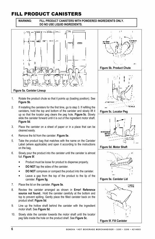
FILL PRODUCT CANISTERS WARNING: FILL PRODUCT CANISTERS WITH POWDERED INGREDIENTS ONLY.
DO NO USE LIQUID INGREDIENTS.
Figure 5b. Product Chute
Figure 5a. Canister Lineup
Figure 5c. Locator Peg
Figure 5d. Motor Shaft
Figure 5e. Canister Lid
1. Rotate the product chute so that it points up (loading position). See Figure 5b.
2. If installing the canisters for the first time, go to step 3. If refilling the canisters, hold the top and bottom of the canister and slowly lift it up so that the locator peg clears the peg hole. Figure 5c. Slowly slide the canister forward until it is out of the ingredient motor shaft. Figure 5d.
3. Place the canister on a sheet of paper or in a place that can be cleaned easily.
4. Remove the lid from the canister. Figure 5e.
5. Take the product bag that matches with the name on the Canister Label (where applicable) and open it according to the instructions on the bag.
6. Slowly pour the product into the canister until the canister is almost full. Figure 5f.
• Product must be loose for product to dispense properly.
• DO NOT tap the sides of the canister.
• DO NOT compress or compact the product into the canister.
• Leave a gap from the top of the product to the lip of the canister. Figure 5g.
7. Place the lid on the canister. Figure 5e.
8. Review the canister arranged as shown in Error! Reference source not found.. Hold the canister carefully at the bottom and top to prevent spilling. Gently place the filled canister back on the product shelf. Figure 5d.
9. Line up the hollow shaft behind the canister with the ingredient motor shaft. See Figure 5d.
10. Slowly slide the canister towards the motor shaft until the locator peg falls inside the hole on the product shelf. See Figure 5c.
Figure 5f. Fill Canister

G E N E V A - H O T B E V E R A G E M E R C H A N D I S E R • 3 2 0 5 • 3 2 0 6 • 4 2 1 4 8 0 3 7
11. Rotate the product chute so that it points down (dispense position) to the whipper bowl. See Figure 5e.
12. Repeat above steps for all other canisters.
Figure 5g. Do Not Pack
CHANGE MENU SELECTION LABELS
Figure 6a. Bottom Wing Nut
Figure 6b. Inside Wing Nuts
Figure 6c. Remove Top Sign Front
1. Remove and save the wing nut located on the right side below the cup compartment (as viewed from behind the door). See Figure 6a.
2. Open the cup compartment door. Remove and save the wing nuts located on the right corner of the cup compartment. Loosen the 2 wing nut holding Top Cap molding. See Figure 6b.
3. Go to the front of the cabinet door, lift Top Cap Molding and loosen the Retaining Strip located on the left side of the Top Sign Front. Remove and save the Retaining Strip and Top Sign Front. See Figure 6c.
4. Place the Top Sign Front on a clean and non-scratching surface.
5. Locate the menu selection label from behind the Top Sign Front. See Figure 6d. Carefully slide the menu selection label out of the pocket and slowly pull on the exposed tab.
Figure 6d. Menu Selection Label
6. Insert the new menu selection label through the slots. Check the front of the Top Sign Front to make sure that the menu selection labels are correctly aligned.
7. Insert the right edge of the Top Sign Front through the slot of the right side Retaining Strip. See Figure 6c.
8. Slip the left side Retaining Strip over the left edge of the Top Sign Front. Push the Retaining Strip back into place. See Figure 6c.
9. Reinstall and tighten the wing nuts saved from steps 1 and 2. See Figure 6a and Figure 6b.

8 G E N E V A - H O T B E V E R A G E M E R C H A N D I S E R • 3 2 0 5 • 3 2 0 6 • 4 2 1 4 8 0 3
CUP SIZE ADJUSTMENT
The cup mechanism has been factory adjusted for 8.25oz cup. Follow the instructions below to adjust the cup (diameter) size.
Figure 8a. Cup Compartment Latch
Figure 8b. Cup Diameter Adjustment (Pre-NOV2007)
Figure 8c. Cup Diameter Adjustment (Post-NOV2007)
1. Unlock the cup compartment door by sliding the plastic latch to the right. See Figure 8a. Open the cup compartment door.
2. Take a cup from the stack of cups that will be used in the machine and place the cup in the cup dispenser ring.
3. While facing the back of the door, find the cup dispenser adjustment screw located on the right side of the cup dispenser. Use a Phillips screwdriver to loosen the screw. DO NOT remove the screw. See Figure 8c & 8c.
3a. Adjust the cup mechanism back and forth so that the cup lip rests on top of the circular cams of the cup dispenser mechanism. See Figure 8d.
3b. Push or tap the cup from the bottom end so that it moves up and down freely. If it does not move freely then go back to step 3a.
3c. Pull the cup from the bottom so that it does not easily slip through the circular cams. If it easily slips through then go back to step 3a.
3d. When steps 3a thru 3c are satisfied then tighten the screw. See Figure 8c.
4. Place a stack of cups to the left of the cup ring. Go to the internal keypad and press the cup test button. The entire cup stack should advance and fall into the cup ring. Pull on the bottom cup so that it does not easily slip through. If it easily slips through then the mechanism is not tight enough so go back to step 3.
Figure 8d. Cup Position In Mechanism

G E N E V A - H O T B E V E R A G E M E R C H A N D I S E R • 3 2 0 5 • 3 2 0 6 • 4 2 1 4 8 0 3 9
SET PRICE FOR SINGLE DRINK VOLUME (LARGE) The following instruction sets the price for the three (3) item types: filled small cup, cup only and a filled large cup. For additional information regarding Set Pricing Modes and Change Prices, please refer to the programming section of this manual.
STEP DISPLAY
1. On internal keypad, press PROG PLEASE ENTER ACCESS CODE
2. On external keypad, enter code 1111 SET PRICING MODE
3. Press 2 or 8. CHANGE PRICES
4. Press 0. LARGE PRICES
5. Press 2 or 8 to scroll to SET ALL PRICES SET ALL PRICES
6. Press0 LARGE PRICES
7. Press 0 to enter a new price
8. Press 4 (move curser left) or 6 (move cursor right), press 2 (increase value) or press 8 (decrease value).
9. Press 0 to accept the price for ALL LARGE PRICES
Price=$0.00
10. Press # (ESCAPE) LARGE PRICES
11. Press 2 or 8 to scroll to other price settings for LARGE PRICE
NOTE: This is to set the prices for individual drinks different from the value set in STEP 9
LARGE PRICE
12. Press 0 to select the drink selection price to change
13. Press 4 (move curser left) or 6 (move cursor right), press 2 (increase value) or press 8 (decrease value).
14. Press 0 to accept the price
COFFEE Price= 000.00
15. Repeat steps 11 to 14 to set prices for any other drinks
16. Press # (ESCAPE) LARGE PRICES
17. Press 2 or 8 to scroll to other selection price settings CUP PRICE
18. Press 0 to accept CUP PRICE
Note: This is DISCOUNTED VALUE for using your own cup
19. Press 4 (move curser left) or 6 (move cursor right), press 2 (increase value) or press 8 (decrease value).
21. Press 0 to accept the DISCOUNTED VALUE
CUP Price=$0.00
22. Press # three times to exit the programming mode. SELECT DRINK TO SHOW PRICE

10 G E N E V A - H O T B E V E R A G E M E R C H A N D I S E R • 3 2 0 5 • 3 2 0 6 • 4 2 1 4 8 0 3
SET PRICE FOR DUAL DRINK VOLUMES (LARGE & REGULAR)
Dual Menu Label set is required to set this option. Order P/N 4214600 Dual Menu Label set.
STEP DISPLAY
1. On internal keypad, press PROG PLEASE ENTER ACCESS CODE
2. On external keypad, enter code 1111 SET PRICING MODE
3. Press 2 or 8. CHANGE PRICES
4. Press 0. LARGE PRICES
5. Press 2 or 8 to scroll to SET ALL PRICES SET ALL PRICES
6. Press 0 LARGE PRICES
7. Press 0 to enter a new price
8. Press 4 (move curser left) or 6 (move cursor right), press 2 (increase value) or press 8 (decrease value).
9. Press 0 to accept the price for ALL LARGE PRICES
Price= $000.00
10. Press 2 or 8 to scroll to REGULAR PRICES REGULAR PRICES
11. Press 0 to enter a new price
12. Press 4 (move curser left) or 6 (move cursor right), press 2 (increase value) or press 8 (decrease value).
13. Press 0 to accept the price for ALL REGULAR PRICES
Price= $000.00
14. Press # (ESCAPE) LARGE PRICES
15. Press 0 to select the drink selection price to change
NOTE: This is to set the prices for individual drinks different from the value set in STEP 9 for LARGE DRINKS
16. Press 4 (move curser left) or 6 (move cursor right), press 2 (increase value) or press 8 (decrease value).
17. Press 0 to accept the price
COFFEE Price= $000.00
18. Press 2 or 8 to scroll to REGULAR PRICES REGULAR PRICES
19. Press 0 to select the drink selection price to change
NOTE: This is to set the prices for individual drinks different from the value set in STEP 13 for REGULAR DRINKS
20. Press 4 (move curser left) or 6 (move cursor right), press 2 (increase value) or press 8 (decrease value).
21. Press 0 to accept the price
COFFEE Price= $000.00
22. Press 2 or 8 to scroll to other selection price settings CUP PRICE
23. Press 0 to accept CUP PRICE
Note: This is DISCOUNTED VALUE for using your own cup
24. Press 4 (move curser left) or 6 (move cursor right), press 2 (increase value) or press 8 (decrease value).
21. Press 0 to accept the DISCOUNTED VALUE
CUP Price= $000.00
22. Press # three times to exit the programming mode. SELECT DRINK TO SHOW PRICE

G E N E V A - H O T B E V E R A G E M E R C H A N D I S E R • 3 2 0 5 • 3 2 0 6 • 4 2 1 4 8 0 3 11
FILL CUP COMPARTMENT
The cup mechanism has been factory adjust for 8.25 oz. cup. Follow the instructions below to adjust the cup diameter size.
Figure 9a. Cup Spirals
Figure 9b. Cup Stacks
Figure 9c. Keypad Cup Test
Figure 9d. Counterweight
1. Check that the top and bottom spirals are aligned with each other and have room for three (3) stacks of cups. See Figure 9a.
2. The cup compartment can have a total of five (5) cup stacks. Load the compartment with cups starting with the first stack in the cup dispenser mechanism followed by three (3) additional cup stacks. See Figure 9b. The cup-stack must be aligned with the top and bottom spirals. Add the fifth cup stack directly in from of the fourth cup stack and place it tight against the left side wall of the compartment.
3. Close and latch the cup compartment door.
4. Find the internal keypad on the left side of the door (as viewed from the rear of the door). Press the square marked “8” right next to “CUP TEST”. See Figure 9c.
4a. The cup should be dispensed via the stainless steel cup chute on and land squarely on the platform of the delivery compartment. See Figure 9e.
4b. If the cup gets stuck at the counter-balance wire, then loosen the counterweight and slide it up to lessen the weight against the cup. See Figure 9d. Repeat step 4.
Figure 9e. Delivery Compartment

12 G E N E V A - H O T B E V E R A G E M E R C H A N D I S E R • 3 2 0 5 • 3 2 0 6 • 4 2 1 4 8 0 3
CUP SIZE ADJUSTMENT
The cup size/volume is factory set at 8.25 oz. Follow the example below to change the cup size setting to 12 oz.
STEP DISPLAY
1. On internal keypad, press PROG PLEASE ENTER ACCESS CODE
2. On external keypad, enter code 3333 INGREDIENT TIMES
3. Using 2 or 8 Scroll to CONFIGURE MC CONFIGURE MC
4. Press 0 8.25 oz
5. Using 2 or 8 Scroll to 12 oz 12 oz
6. Press 0 to confirm selection 12 oz
7. Press # to exit programming mode SELECT DRINK TO SHOW PRICE

G E N E V A - H O T B E V E R A G E M E R C H A N D I S E R • 3 2 0 5 • 3 2 0 6 • 4 2 1 4 8 0 3 13
FLUSH HEATER TANK, BOWL & BREWER
]
Figure 11a. Waste Buckets
INSTALL WASTE CONTAINERS
1. Place a trash liner (10 Gal) inside the large waste container. Place the waste container under the heater tank overflow tube and the brewer.
2. Place the small bucket under the cup dispensing tubes. See Figure 11a.
FLUSH WHIPPER BOWLS & BREWER
1. Go to the internal keypad, press the square next to FLUSH to clean the whipper bowls. See Figure 11b.
2. In a Fresh Brew Machine, after step 3, press the square next to FLUSH BREWERS to clean the brewer and filter. See Figure 11b
Figure 11b. Keypad Flush
FLUSH HOT WATER TANK
1. Turn off the Power Switch and shut off the main water valve to the machine. Remove the plug from the hot water tank drain tube and empty the tank contents into the drain bucket. See Figure 11b.
2. Reinstall the plug to the drain tube. Open the main water valve to the machine and turn on the Power Switch.

14 G E N E V A - H O T B E V E R A G E M E R C H A N D I S E R • 3 2 0 5 • 3 2 0 6 • 4 2 1 4 8 0 3
DRIP CATCHER
Figure 12a. Drip Catcher
Place a cup on the Drip Catcher Holder to catch any remaining liquid in the base of the cup station from dripping onto the floor when the door is opened during servicing.
1. The Drip Catcher is located on the back of the door underneath the Cup Station.
2. Place a 7 oz or 8.25 oz cup on the Drip Catcher Cup Holder. See Figure 12a.
3. IMPORTANT: Place the Overflow Bucket Sensor inside the drain bucket before closing the door. See Figure 12b.
Figure 12b. Waste Bucket Sensor

G E N E V A - H O T B E V E R A G E M E R C H A N D I S E R • 3 2 0 5 • 3 2 0 6 • 4 2 1 4 8 0 3 15
GENERAL DESCRIPTION The operational components which form a Hot Beverage Merchandiser are housed in a metal enclosure, access to which is gained by a swivel door secured by a key operated locking mechanism. Turning the key in the lock released a door handle, which allows a three or single point locking mechanism to move to the unlocked state and the door to be opened. With the door open the mains isolation switch for ON/OFF operation of the machine is visible in the top left corner of the machine (above and behind the product canisters).
Equipment inside the cabinet is arranged in two sections: front and rear. On opening the door, the Operator is immediately faced with those items of equipment to which he or she requires access, e.g. Ingredient Canisters, Cup Compartment, Coin Mechanism, Waste Buckets, etc. The remaining items of equipment, e.g. Water Heater, Valves, Electrical and electronics components, etc, to which specifically the Engineer requires access (and from which the Operator must be shielded) are located behind the Ingredient Canisters and Whipper Motor and Dispense Head Assembly panel, at the rear of the cabinet.
CABINET FRONT
The Cup Drop Assembly, Coin Mechanism, Controller Board and Cup Station are fitted to the rear of the door. The Customer’s keypad is fitted to the front panel and is connected to the Controller board via a cable assembly.
Ingredient canisters are located on a shelf approximately half way up the cabinet. At the front of the shelf is a duct assembly to which an extractor fan is connected. The fan pulls air from the extract duct, which in turn removes steam/moist air from the mixing systems, which are located on a vertical panel below the canister shelf. The moving dispense head protrudes through and is fastened to this vertical panel and in the case of the fresh brew versions this vertical panel also provides the mounting for the fresh brew units.
On the fresh brew version a large plastic waste bucket is located underneath the Brewer Unit, in addition to the small one placed at the front of the cabinet, beneath the Cup Station (when the door is closed). Water heater overflow pipes, and a water level probe, are directed into the smaller bucket. When the waste liquid in the bucket(s) reaches the level sensor probe, the water supply inlet is shut off and the machine is rendered inoperable.
CABINET REAR
Access to the components and equipment in the rear section of the cabinet is obtained by removing the ingredient canisters and the relevant back panel.
Cold water enters the cabinet through an aperture in the rear panel and connects to a twin chamber inlet valve for the hot water supply. A length of tubing takes the water supply from the inlet valve into the water heater and then to the water heater tank located at the top of the cabinet. Hot water in the correct quantity is then directed from the tank to the appropriate mixing bowl via a solenoid operated dispense valve. A dispense valve is associated with each ingredient. Any overflow from the tank is directed into the waste bucket via an overflow tube. Fitted to this tube is a high temperature cut-out switch, when operated, cuts off the electrical supply to the heater in the tank. The cut-out must then be reset to restore the supply. Another length of tubing facilitates draining of the heater.
A level probe is fitted to the rear of the cabinet door and a similar device is located in the fresh brew waste container. When the door is closed these devices act as contact probes allowing the units control system to monitor the liquid level in the waste containers.
Two printed circuit boards are fitted to the top right hand side of the cabinet rear panel; the DC Remote Input/Output Board (DC RIO) and the Power Supply Unit (PSU). The DC RIO Board provides the high current drives to operate the output devices (valves, motors etc) in response to signals from the Controller Board.
A solid-state relay, located beneath the printed circuit boards, pulses current to the heater in response to signals from the DC RIO Board. The DC RIO board receives signal from the Controller via an I²C link. The temperature of the water in the boiler is measured by the Controller Board using an NTC thermistor mounted at the end of a stainless steel probe immersed in the hot water tank.
WATER SYSTEM
The cold water mains supply enters the machine via double-solenoid operated inlet valve at the rear of the cabinet. This valve controls the flow of water to the unit’s hot water tank via a water filter.
HOT WATER SYSTEM
Water is supplied via the Hot Inlet valve to the heater tank via a water filter where it is heated to the required temperature by a heating element in the tank. Water temperature is controlled by a combined temperature and level probe assembly in the tank which causes the supply to the heater to be removed when the preset

16 G E N E V A - H O T B E V E R A G E M E R C H A N D I S E R • 3 2 0 5 • 3 2 0 6 • 4 2 1 4 8 0 3
temperature is reached. The probe assembly also acts as a level sensor, causing the Hot Inlet valve to open when the water in the tank falls below a preset level. The probe (i.e. the input device) is monitored by the Controller Board, and the water heater and Hot Inlet valve (i.e. the output devices) are controlled by the DC RIO Board in response to signals from the Controller Board.
Depending on the type of hot drink selected, hot water from the heater tank is fed via solenoid operated dispense valves to the appropriate mixing bowl or Brewer Unit container. Ingredients and water are mixed in exact quantities in the mixing bowl or Brewer Unit container. Ingredients and water are mixed in exact quantities in the mixing bowl and then directed to the dispense head. Similarly, water and ingredient are brewed in exact amounts in the Brewer Unit and then directed to the dispense head.
A resettable cut-out sensor, mounted on the boiler lid, cuts off the electrical supply to the tank heater circuit if the water in the tank starts to boil. Additionally, if the fluid level in the overflow waste bucket rises above the preset level, it is detected by a level probe and reported to the Controller Board, which responds by closing the inlet valve via the DC RIO Board and rendering the machine inoperable.
Fig 1.1A Water System Diagram - Instant

G E N E V A - H O T B E V E R A G E M E R C H A N D I S E R • 3 2 0 5 • 3 2 0 6 • 4 2 1 4 8 0 3 17
Fig 1.1B Water System Functional Diagram –Fresh Brew

18 G E N E V A - H O T B E V E R A G E M E R C H A N D I S E R • 3 2 0 5 • 3 2 0 6 • 4 2 1 4 8 0 3
Fig 1.3 Electrical & Electronic System – Functional Diagram

G E N E V A - H O T B E V E R A G E M E R C H A N D I S E R • 3 2 0 5 • 3 2 0 6 • 4 2 1 4 8 0 3 19
INTERNAL KEYPAD FUNCTIONS
Fig 2.1
The internal keypad provides the facility to carry out a number of frequently required machine functions without the necessity to enter any of the user programs.
In most cases a single press of the key initiates the function associated with each button. If a further key press is necessary to end the action it will be the ESC (escape) key.
The functions available from the internal keypad are as follows:
a) ADVANCE COFFEE BREWER - If a coffee brewer is fitted, a single depression of this key will cause the brewer unit to index to its next position in the cycle. The purpose of this function is to allow the brewer to be locked prior to a flush cycle so that cleaning agents can be added.
b) MDB MECH DISPENSE COIN - This key provides a method to empty the change tubes of an MDB coin mechanism, which does not itself possess the necessary buttons to do so. On pressing the key the external display will change to:
EMPTY TUBE $0.05
�,� ENTER OR ESC
The currency value shown will be that of the lower value coin tube in the coin mechanism. The function of the EXTERNAL keys will change as described in section 3 to allow actions to be performed on either the internal or external keypad. Pressing ENTER will cause a coin to be dispensed from the currently selected tube. Pressing the � or � select the next/previous coin tube. Repeated use of the �, � & ENTER keys enables all tubes to be emptied. Pressing the ESC (escape) key ends the process.
c) BREWER FLUSH - This key provides the means to initiate a flush cycle of the fresh brew units. A single press of this key will initiate a cleaning cycle for all brewers fitted to the machine simultaneously. In the case of the instant version this function is redundant.

20 G E N E V A - H O T B E V E R A G E M E R C H A N D I S E R • 3 2 0 5 • 3 2 0 6 • 4 2 1 4 8 0 3
d) PROG - This key activates the code entry sequence required to access the protected levels of the machine control programs. See section 2b.
e) MDB MECH FILL TUBES - If an MDB coin mechanism is fitted this function allows the change tubes to be filled. On pressing the key the external display will change to:
INSERT FLOAT
$0.00
As coins are inserted the value displayed will reflect the total value of the money inserted. Pressing ESC (escape) will cause the machine to return to normal operation and zero the credit.
f) CUP TEST - Causes a cup to be dispensed by the cup drop mechanism. The cup spiral will not index unless a selection is made or a cup test performed.
g) DRINK TEST - Allows the next selection to be taken as a free vend.
h) COUNTERS - Pressing the counters key places the machine in manual audit mode. Audit data is accessed via a series of menus. The chart below shows the menu headings in bold text while the key presses required to navigate the menu are shown in italics. While in this mode the functions of the EXTERNAL keypad change to allows the menus to be accessed from the same side of the door as the display – see section 3 paragraph 5 for button function in this mode.
G E N E V A - H O T B E V E R A G E M E R C H A N D I S E R • 3 2 0 5 • 3 2 0 6 • 4 2 1 4 8 0 3 21
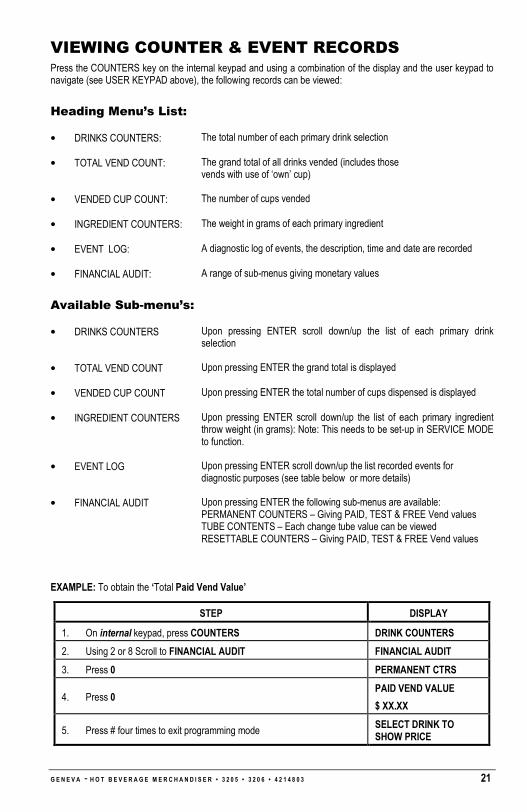
VIEWING COUNTER & EVENT RECORDS Press the COUNTERS key on the internal keypad and using a combination of the display and the user keypad to navigate (see USER KEYPAD above), the following records can be viewed:
Heading Menu’s List:
• DRINKS COUNTERS: The total number of each primary drink selection
• TOTAL VEND COUNT: The grand total of all drinks vended (includes those vends with use of ‘own’ cup)
• VENDED CUP COUNT: The number of cups vended
• INGREDIENT COUNTERS: The weight in grams of each primary ingredient
• EVENT LOG: A diagnostic log of events, the description, time and date are recorded
• FINANCIAL AUDIT: A range of sub-menus giving monetary values
Available Sub-menu’s:
• DRINKS COUNTERS Upon pressing ENTER scroll down/up the list of each primary drink selection
• TOTAL VEND COUNT Upon pressing ENTER the grand total is displayed
• VENDED CUP COUNT Upon pressing ENTER the total number of cups dispensed is displayed
• INGREDIENT COUNTERS Upon pressing ENTER scroll down/up the list of each primary ingredient throw weight (in grams): Note: This needs to be set-up in SERVICE MODE to function.
• EVENT LOG Upon pressing ENTER scroll down/up the list recorded events for diagnostic purposes (see table below or more details)
• FINANCIAL AUDIT Upon pressing ENTER the following sub-menus are available: PERMANENT COUNTERS – Giving PAID, TEST & FREE Vend values TUBE CONTENTS – Each change tube value can be viewed RESETTABLE COUNTERS – Giving PAID, TEST & FREE Vend values
EXAMPLE: To obtain the ‘Total Paid Vend Value’
STEP DISPLAY
1. On internal keypad, press COUNTERS DRINK COUNTERS
2. Using 2 or 8 Scroll to FINANCIAL AUDIT FINANCIAL AUDIT
3. Press 0 PERMANENT CTRS
4. Press 0 PAID VEND VALUE
$ XX.XX
5. Press # four times to exit programming mode SELECT DRINK TO SHOW PRICE
22 G E N E V A - H O T B E V E R A G E M E R C H A N D I S E R • 3 2 0 5 • 3 2 0 6 • 4 2 1 4 8 0 3
TAKING A TEST VEND Press the DRINK TEST key on the internal keypad once and then make a drink selection on the external keypad.
If more than one test vend is required, repeat the above procedure.
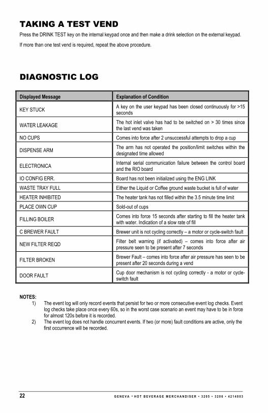
DIAGNOSTIC LOG
Displayed Message Explanation of Condition
KEY STUCK A key on the user keypad has been closed continuously for >15 seconds
WATER LEAKAGE The hot inlet valve has had to be switched on > 30 times since the last vend was taken
NO CUPS Comes into force after 2 unsuccessful attempts to drop a cup
DISPENSE ARM The arm has not operated the position/limit switches within the designated time allowed
ELECTRONICA Internal serial communication failure between the control board and the RIO board
IO CONFIG ERR. Board has not been initialized using the ENG LINK
WASTE TRAY FULL Either the Liquid or Coffee ground waste bucket is full of water
HEATER INHIBITED The heater tank has not filled within the 3.5 minute time limit
PLACE OWN CUP Sold-out of cups
FILLING BOILER Comes into force 15 seconds after starting to fill the heater tank with water. Indication of a slow rate of fill
C BREWER FAULT Brewer unit is not cycling correctly – a motor or cycle-switch fault
NEW FILTER REQD Filter belt warning (if activated) – comes into force after air pressure seen to be present after 7 seconds
FILTER BROKEN Brewer Fault – comes into force after air pressure has seen to be present after 20 seconds during a vend
DOOR FAULT Cup door mechanism is not cycling correctly - a motor or cycle-switch fault
NOTES: 1) The event log will only record events that persist for two or more consecutive event log checks. Event
log checks take place once every 60s, so in the worst case scenario an event may have to be in force for almost 120s before it is recorded.
2) The event log does not handle concurrent events. If two (or more) fault conditions are active, only the first occurrence will be recorded.

G E N E V A - H O T B E V E R A G E M E R C H A N D I S E R • 3 2 0 5 • 3 2 0 6 • 4 2 1 7 3 5 6 1
PROGRAMMING The Hot Beverage Merchandiser has a comprehensive configuration program to allow the behavior and function of the machine to be changed to meet a customer’s requirement. There are three levels of access to the configuration functions of the machine. Access to each level is protected by means of a four-digit code. The facilities available at each level are shown below:
1. Operator level access
� Access to price related features only.
� Factory default Code 1111.
2. Manager level access
� Access to Price related features.
� Inhibit selections
� Limited range modification of recipes.
� Change Operator level access code.
� Factory default Code 3333.
3. Engineer level access
� Full access all features
� Factory default code 4444.
ACCESSING THE USER PROGRAMS
The programs are accessed by pressing key 5 (PROG) on the INTERNAL keypad. The EXTERNAL display will then prompt for input of a four-digit entry code. The code is input using the numbers printed on the keys of the INTERNAL keypad.
� After pressing the PROG key the display will change to:
PLEASE ENTER ACCESS CODE
� Use the numbered keys on the keypad to enter the correct code. It is not necessary to press ENTER. The code will be checked on entry of the fourth digit. Three attempts are allowed before the PROG key must be pressed again. On entry of a valid code the display will change to the menu heading appropriate to the level of access. While in programming mode the functions of the external keypad change to facilitate navigation of the program using the EXTERNAL keypad.
In the event that the code has been lost or when fitting an un-programmed replacement board it is necessary to complete the circuit between the two pins of the two pin header labeled ENG LINK on the Control board. This bypasses the entry of the four-digit code, giving engineer level access immediately upon processing PROG key. If the ENG LINK is left in place during power up, the machine will boot straight into the engineers program with full access.
� Note Regarding Power Up Problems
The Hot Beverage Merchandiser electronics control system has two major elements. These are the Control board and the DC RIO board. The two boards communicate via a three wire Inter Integrated Circuit bus (I²C bus). Some faults affecting the I²C bus or Control board configuration can result in persistent system resets. To allow recovery/diagnosis from such situations the control system provides an Access Window to a special ‘safe mode’ shortly after power is switched on. It is possible to enter engineer’s mode during this window.
Some configuration faults related to initialized boards do not allow the system to get even this far through start up, in which case it is necessary to insert the ENG LINK before switching the power on. In this case the machine will boot straight into the engineer’s program.
In both cases the I²C bus linking the electronics boards is disabled. Without communication between the DC RIO board and the Control board the OUTPUT TEST facility is ineffective and the state of some inputs will be misreported in the INPUT TEST routines. As a reminder to this effect the sound associated with a key press is truncated to a very short pip rather than a beep.

2 G E N E V A - H O T B E V E R A G E M E R C H A N D I S E R • 3 2 0 5 • 3 2 0 6 • 4 2 1 7 3 5 6
USER KEYPAD
Having entered a valid code, the keys on the USER keypad are used to navigate and use the functions of the user programs. In programming mode the keys assume the following alternative functions:
KEY FUNCTION
���� Move UP a list of menu options or increment a number.
���� Move DOWN a list of menu options or decrement a number.
Move the cursor LEFT.
���� Move the cursor RIGHT.
ESC ESCAPE - move to previous menu option or reject values entered.
ENTER ENTER the menu option displayed or accept the changes made.

G E N E V A - H O T B E V E R A G E M E R C H A N D I S E R • 3 2 0 5 • 3 2 0 6 • 4 2 1 7 3 5 6 3
PROGRAM FUNCTIONS
The following table shows the functions available and the access level required to use them within the Hot Beverage Merchandiser configuration program:
ACCESS LEVEL REQUIRED FUNCTION
OPERATOR MANAGER ENGINEER
Ingredient Times - YES (limited) YES
Set Date/Time - YES YES
Set Pricing Mode YES YES YES
Change Prices YES YES YES
Inhibit Drink - YES YES
Alter Drink Name - YES YES
Timed Activities - - YES
Temp Settings - - YES
Output Test - - YES
Input Test - - YES
Set Product Consts - - YES
Machine Status - - YES
Set Dry Vend Mode - - YES
Serial Number - - YES
Configure Machine - YES (limited) YES
MDB Config - - YES
EVA-DTS Config - - YES
Product Codes - - YES
Operator’s Code - YES YES
Manager’s Code - - YES
Engineer’s Code - - YES
Free Drink Code YES YES
Edit Drink Map - - YES
Card Actions - - YES
Editable Text - - YES
Depressurize CBR - YES YES

4 G E N E V A - H O T B E V E R A G E M E R C H A N D I S E R • 3 2 0 5 • 3 2 0 6 • 4 2 1 7 3 5 6
PROGRAMMING SEQUENCE OF OPERATIONS
The method of navigating the menu structure is consistent throughout the program. The � and � keys are used to index through the headings in a particular level or increment/decrement value. Pressing ENTER will select a submenu or confirm a change while ESC (escape) will reject a change or return to the previous menu level. The sequence for accessing a menu option and the accessing a submenu within that option and finally selecting and changing a parameters value, is shown diagrammatically in Fig 3.1.
Fig 3.1 Accessing An Option Setting – Flow Diagram

G E N E V A - H O T B E V E R A G E M E R C H A N D I S E R • 3 2 0 5 • 3 2 0 6 • 4 2 1 7 3 5 6 5
MENU OPTIONS
INGREDIENT TIMES
Ingredient Times provides access to a set of submenus, which allow modification of the parameters controlling the recipe and dispensing of individual drinks. The actual content of the sub-menu is dependent on the configuration of the machine. That is for example an Instant Hot version will have different drinks in its Ingredient Times sub menu to a Double Fresh Brew version fitted with a carbonator. In general the entries of the Ingredient Times menu will consist only of the drinks available on that particular configuration of machine. The Hot Beverage Merchandiser range has a number of pre-defined configurations. For each configuration each selection button is associated with a particular drink. This association is fixed for each configuration. For example if the top left button in a given configuration provides an instant coffee drink then the Coffee entry in the Ingredient sub menu will allow adjustment of a limited number of parameters relating to a coffee selection, it is not possible to reprogram the button to behave as a completely different drink e.g. an Espreschoc.
For each selection a user with Manager level access is grated a limited range adjustment on a subset of the parameters. This allows the site-based personnel to perform minor taste profile modifications without the need to call an engineer. The limited range adjustment is implemented as a multiplying scale factor of between 75% and 125%. In manager’s mode the limited range of adjustment permitted is displayed as a signed value between -25% and +25% and can be changed in 5% increments. For example the limited range strength control for the coffee ingredient of an Espreschoc selection, which has had its coffee ingredient increased by 5%would appear to a manger level user as:
When viewed with engineers level access this would appear as:
In each case the same parameter is being viewed.
The following tables describe the parameters that can be adjusted for each drink, and indicate the parameters visible at the different access levels. The drinks available in each configuration are described in Table 14.b later in this Section.
OP: Coffee Mod
105
OP: Coffee Mod
+5%

6 GENEVA - H
OT B
EVERAGE M
ERCHANDIS
ER • 3
205 • 3
206 • 4
217356
7 oz
Large
50
8
1
23
55
15
10
18
13
10
14
3
24
7 oz
Regular
50
8
1
17
41
13
10
14
10
8
10
2
20
8 1/4 oz
Large
50
8
1
27
65
18
10
21
15
12
17
4
28
8 1/4 oz
Regular
50
8
1
20
49
15
10
16
11
9
12
3
24
9 oz
Large
50
8
1
29
71
20
10
23
17
13
18
5
31
9 oz
Regular
50
8
1
22
53
17
10
17
13
10
14
3
25
10 oz
Large
50
8
1
33
79
22
10
25
19
14
20
5
34
10 oz
Regular
50
8
1
24
59
18
10
19
14
11
15
3
29
12 oz
Large
50
8
1
39
95
26
10
28
22
17
24
6
41
12oz
Regular
50
8
1
29
71
22
10
21
17
13
18
4
35
Units
.1s
.1s
.1s
.1s
.1s
.1s
Ratio x 10
.1s
.1s
.1s
.1s
.1s
.1s
Function
Delay after coffee and water are added to brew chamber before brewer closes
Delay before the Coffee ingredient is dispensed
Delay before the 2nd shot of Coffee Water is dispensed
Delay before the 1st shot of Coffee Water is dispensed
Coffee brewer dispense valve open duration. The water time is split into 2 equal shots of water
Milk & Sugar valve opening time
Balancing factor to account for difference in flow rate between Milk/Sugar valve and brewer valve. If white/sugar drink is smaller than black version increase VAL FACTOR and vice versa. Range 8-14.v
Coffee Ingredient Auger Control (30 = 12.5 - 13g)
Auger run time for Optional ingredient if selected
Increment applied to sugar auger run time when extra sugar selected
Auger run time for Optional ingredient if selected
Increment applied to milk auger run time when extra milk selected
Duration of first air pump operation
FRESH BREW RECEIPE CHARTS (SOFTWARE REV 29E)
FRESH BREW COFEE
Parameter Name
INFUSION TIME
COFFEE START TIME
CWTR START TIME 1
CWTR START TIME 2
WATER TIME
M&S WATER TIME
VALVE FACTOR
COFFEE ING TIME
SUGAR TIME
SUGAR ADJUSTMENT
MILK TIME
MILK ADJUSTMENT
PUMP 1 DURATION

GENEVA - H
OT B
EVERAGE M
ERCHANDIS
ER • 3
205 • 3
206 • 4
217356
7
38
34
27
14
0
20
20
100
35
29
23
12
0
20
20
100
45
40
32
17
0
20
20
100
41
34
28
14
0
20
20
100
49
44
35
18
0
20
20
100
45
38
30
15
0
20
20
100
54
49
39
20
0
20
20
100
50
41
33
17
0
20
22
100
65
59
47
24
0
20
20
100
60
50
40
20
0
20
20
100
.1s
.1s
.1s
.1s
.1s
.1s
.1s
%
Inactive period following first air pump operation
Duration of second air pump operation
Inactive period following second air pump operation
Run time for coffee mixer motor referenced to the beginning of the first air pump activity
Adds hot water directly to cup
Idle time before head retracts following dispense of selection with no optional components
Idle time before head retracts following dispense of selection where milk or sugar have been selected
Manager level control applied to SUGAR TIME. The actual sugar auger run time will be SUGAR TIME x OP: Sugar Mod/100
PUMP 1 DELAY
PUMP 2 DURATION
PUMP 2 DELAY
MIXER TIME
HOT WATER TIME
BLACK DRAIN TIME
WHITE DRAIN TIME
OP: Sugar Mod

8 GENEVA - H
OT B
EVERAGE M
ERCHANDIS
ER • 3
205 • 3
206 • 4
217356
7 oz
Large
58
7 oz
Regular
44
8 1/4 oz
Large
69
8 1/4 oz
Regular
52
9 oz
Large
75
9 oz
Regular
56
10 oz
Large
83
10 oz
Regular
62
12 oz
Large
100
12oz
Regular
75
Units
.1s
Function
Coffee Whipper
WHIPPED COFFEE (FRESH BREW)
Parameter Name
MIXER TIME

GENEVA - H
OT B
EVERAGE M
ERCHANDIS
ER • 3
205 • 3
206 • 4
217356
9
7 oz
Large
58
7 oz
Regular
44
8 1/4 oz
Large
69
8 1/4 oz
Regular
52
9 oz
Large
75
9 oz
Regular
56
10 oz
Large
83
10 oz
Regular
62
12 oz
Large
100
12oz
Regular
75
Units
.1s
Function
Coffee Whipper
WHIPPED DECAF (FRESH BREW)
Parameter Name
MIXER TIME

10 GENEVA - H
OT B
EVERAGE M
ERCHANDIS
ER • 3
205 • 3
206 • 4
217356
7 oz
Large
50
8
1
23
55
15
10
18
13
10
14
3
24
7 oz
Regular
50
8
1
17
41
13
10
14
10
8
10
2
20
8 1/4 oz
Large
50
8
1
27
65
18
10
21
15
12
17
4
28
8 1/4 oz
Regular
50
8
1
20
49
15
10
16
11
9
12
3
24
9 oz
Large
50
8
1
29
71
20
10
23
17
13
18
5
31
9 oz
Regular
50
8
1
22
53
17
10
17
13
10
14
3
26
10 oz
Large
50
8
1
33
79
22
10
25
19
14
20
5
34
10 oz
Regular
50
8
1
24
59
18
10
19
14
11
15
3
29
12 oz
Large
50
8
1
39
95
26
10
28
22
17
24
6
41
12oz
Regular
50
8
1
29
71
22
10
21
17
13
18
4
35
Units
.1s
.1s
.1s
.1s
%
0
Ratio x 10
.1s
.1s
.01s
.01s
.1s
.1s
Function
Delay after coffee and water are added to brew chamber before brewer closes
Delay before the Coffee ingredient is dispensed
Delay before the 2nd shot of Coffee Water is dispensed
Delay before the 1st shot of Coffee Water is dispensed
Coffee brewer dispense valve open duration. The water time is split into 2 equal shots of water
Milk & Sugar valve opening time
Balancing factor to account for difference in flow rate between Milk/Sugar valve and brewer valve. If white/sugar drink is smaller than black version increase VF and vice versa. Range 8-14.
Coffee Ingredient Auger Control (30 = 12.5 - 13g)
Auger run time for Optional ingredient if selected
Increment applied to sugar auger run time when extra sugar selected
Auger run time for Optional ingredient if selected
Increment applied to milk auger run time when extra milk selected
Duration of first air pump operation
FRESH BREW DECAF COFFEE
Parameter Name
INFUSION TIME
COFFEE START TIME
CWTR START TIME 1
CWTR START TIME 2
WATER TIME
M&S WATER TIME
VALVE FACTOR
COFFEE ING TIME
SUGAR TIME
SUGAR ADJUSTMENT
MILK TIME
MILK ADJUSTMENT
PUMP 1 DURATION

GENEVA - H
OT B
EVERAGE M
ERCHANDIS
ER • 3
205 • 3
206 • 4
217356
11
34
27
14
0
20
20
100
100
100
100
29
23
12
0
20
20
100
100
100
100
41
32
17
0
20
20
100
100
100
100
34
28
14
0
20
20
100
100
100
100
44
35
18
0
20
20
100
100
100
100
38
30
15
0
20
20
100
100
100
100
49
39
20
0
20
20
100
100
100
100
42
33
17
0
20
22
100
100
100
100
59
47
24
0
20
20
100
100
100
100
50
40
20
0
20
20
100
100
100
100
.1s
.1s
.1s
.1s
.1s
.1s
%
%
%
%
Duration of second air pump operation
Inactive period following second air pump operation
Run time for coffee mixer motor referenced to the beginning of the first air pump activity
Adds hot water directly to cup
Idle time before head retracts following dispense of selection with no optional components
Idle time before head retracts following dispense of selection where milk or sugar have been selected
Manager level control applied to SUGAR TIME. The actual sugar auger run time will be SUGAR TIME x OP: Sugar Mod/100
Manager level control applied to MILK TIME. The actual milk auger run time will be MILK TIME x OP: Milk Mod/100
Manager level control applied to COFFEE TIME. The actual sugar auger run time will be COFFEE TIME x OP: Coffee Mod/100
Manager level control applied to WATER TIME. The actual milk auger run time will be WATER TIME x OP: Water Mod/100
PUMP 2 DURATION
PUMP 2 DELAY
MIXER TIME
HOT WATER TIME
BLACK DRAIN TIME
WHITE DRAIN TIME
OP: Sugar Mod
OP: Milk Mod
OP: Coffee Mod
OP: Water Mod

12 GENEVA - H
OT B
EVERAGE M
ERCHANDIS
ER • 3
205 • 3
206 • 4
217356
7 oz
Large
50
0
4
12
29
14
13
0
12
3
13
12
14
7 oz
Regular
50
0
4
9
22
11
10
0
9
2
10
12
12
8 1/4 oz
Large
50
0
4
14
34
17
15
0
14
3
15
12
17
8 1/4 oz
Regular
50
0
4
10
26
12
11
0
10
2
11
12
14
9 oz
Large
50
0
4
15
38
18
17
0
15
4
17
12
18
9 oz
Regular
50
0
4
11
28
14
13
0
11
2
12
12
15
10 oz
Large
50
0
4
17
42
20
19
0
17
4
18
12
20
10 oz
Regular
50
0
4
13
31
15
14
0
12
2
14
12
17
12 oz
Large
50
0
4
20
50
24
22
0
20
5
22
12
24
12oz
Regular
50
0
4
15
38
18
17
0
15
3
17
12
20
Units
.1s
.1s
.1s
.1s
.1s
.1s
.1s
.1s
.1s
.1s
.1s
ratio
.1s
Function
Delay after coffee & water are added to brew chamber before brewer closes
Delay before the Coffee ingredient is dispensed
Delay before the 2nd shot of Coffee Water is dispensed
Delay before the 1st shot of Coffee Water is dispensed
Coffee brewer dispense valve open duration. The water time is split into 2 equal shots of water
Milk & Sugar valve opening time
Auger run time for Optional ingredient if selected
Increment applied to milk auger run time when extra milk selected
Auger run time for Optional ingredient if selected
Increment applied to milk auger run time when extra milk is selected
Coffee Ingredient Auger Control (30 = 12.5 - 13g)
Balancing factor to account for difference in flow rate between Milk/Sugar valve and brewer valve. If white/sugar drink is smaller than black version increase VALVE FACTOR and vice versa. Range 8-14.
Duration of first air pump operation
ESPRESSO (FRESH BREW COFFEE)
Parameter Name
INFUSION TIME
COFFEE START TIME
CWTR START TIME 1
CWTR START TIME 2
WATER TIME
M&S WATER TIME
SUGAR TIME
SUGAR ADJUSTMENT
MILK TIME
MILK ADJUSTMENT
COFFEE ING TIME
VALVE FACTOR
PUMP 1 DURATION

GENEVA - H
OT B
EVERAGE M
ERCHANDIS
ER • 3
205 • 3
206 • 4
217356
13
27
11
20
41
0
20
20
100
100
100
23
9
18
35
0
20
20
100
100
100
32
12
24
59
0
20
20
100
100
100
28
10
21
51
0
20
20
100
100
100
35
14
26
53
0
20
20
100
100
100
30
11
23
45
0
20
20
100
100
100
39
15
29
59
0
20
20
100
100
100
33
13
25
50
0
20
22
100
100
100
47
18
35
71
0
20
20
100
100
100
40
15
30
60
0
20
20
100
100
100
.1s
.1s
.1s
.1s
.1s
.1s
.1s
%
%
%
Inactive period following first air pump operation
Duration of second air pump operation
Inactive period following second air pump operation
Run time for coffee mixer motor referenced to the beginning of the first air pump activity
Run time for hot water directly into cup
Idle time before head retracts following dispense of selection with no optional components.
Idle time before head retracts following dispense of selection where milk or sugar have been selected
Manager level control applied to SUGAR TIME. The actual sugar auger run time will be SUGAR TIME x OP: Sugar Mod/100
Manager level control applied to MILK TIME. The actual milk auger run time will be MILK TIME x OP: Milk Mod/100
Manager level control applied to COFFEE TIME. The actual sugar auger run time will be COFFEE TIME x OP: Coffee Mod/100
PUMP 1 DELAY
PUMP 2 DURATION
PUMP 2 DELAY
MIXER TIME
HOT WATER TIME
BLACK DRAIN TIME
WHITE DRAIN TIME
OP: Sugar Mod
OP: Milk Mod
OP: Coffee Mod

14 GENEVA - H
OT B
EVERAGE M
ERCHANDIS
ER • 3
205 • 3
206 • 4
217356
7 oz
Large
13
0
0
18
29
48
0
20
29
35
55
24
34
27
27
13
20
27
7 oz
Regular
10
0
0
13
22
41
0
13
22
26
47
20
29
23
23
10
18
23
8 1/4 oz
Large
15
0
0
21
34
56
0
24
34
41
65
28
41
32
32
15
24
32
8 1/4 oz
Regular
11
0
0
15
26
48
0
16
26
31
55
24
34
28
28
11
21
28
9 oz
Large
17
0
0
23
38
62
0
26
38
45
71
31
44
35
35
17
26
35
9 oz
Regular
12
0
0
17
28
53
0
17
28
34
60
26
38
30
30
13
23
30
10 oz
Large
18
0
0
25
42
68
0
29
42
50
78
34
49
39
39
19
29
39
10 oz
Regular
14
0
0
19
31
58
0
19
31
38
66
29
42
33
33
14
25
33
12 oz
Large
22
0
0
30
50
82
0
35
50
60
94
41
59
47
47
22
35
47
12oz
Regular
17
0
0
23
38
70
0
23
38
45
80
35
50
40
40
17
30
40
Units
1.0s
.1s
.1s
.1s
0.1s
0.1s
0.1s
0.1s
0.1s
0.1s
0.1s
0.1s
0.1s
0.1s
0.1s
0.1s
0.1s
0.1s
Function
Coffee Ingredient Auger Control
Delay before the Coffee ingredient is dispensed
Delay before the 2nd shot of Coffee Water is dispensed
Delay before the 1st shot of Coffee Water is dispensed
Coffee brewer dispense valve open duration. The water time is split into 2 equal shots of water
Run time for coffee mixer motor referenced to the beginning of the first air pump activity
Auger run time for ingredient
Auger run time for ingredient
Choc/Topping dispense valve open duration
Run time for choc/topping mixer motor
Brewer cycle start time
Duration of first air pump operation
Inactive period following first air pump operation
Duration of second air pump operation
Inactive period following second air pump operation
Auger run time for Optional ingredient if selected
Sugar valve opening time
0
CAFÉ MOCHA (FRESH BREW COFFEE)
Parameter Name
COFFEE TIME
COFFEE START TIME
CWTR START TIME 1
CWTR START TIME 2
COFFEE WATER
COFFEE MIXER TIME
TOPPING TIME
CHOCOLATE TIME
CHOC WATER TIME
CHOC MIXER TIME
BREWER START
PUMP 1 DURATION
PUMP 1 DELAY
PUMP 2 DURATION
PUMP 2 DELAY
SUGAR TIME
SUGAR WTR TIME
SUGAR MIXER TIME

GENEVA - H
OT B
EVERAGE M
ERCHANDIS
ER • 3
205 • 3
206 • 4
217356
15
0
0
100
100
0
0
100
100
0
0
100
100
0
0
100
100
0
0
100
100
0
0
100
100
0
0
100
100
0
22
100
100
0
0
100
100
0
0
100
100
0.1s
0.1s
%
%
0
0
Manager level control applied to TOPPING TIME. The actual topping auger run time will be TOPPING TIME x OP: Topping Mod/100
Manager level control applied to CHOCOLATE TIME. The actual chocolate auger run time will be CHOCOLATE TIME x OP: Choc Mod/100
MILK WTR TIME
MILK MIXER TIME
OP: Topping Mod
OP: Choc Mod

16 GENEVA - H
OT B
EVERAGE M
ERCHANDIS
ER • 3
205 • 3
206 • 4
217356
7 oz
Large
10
50
0
0
18
29
23
16
23
45
13
10
31
24
34
27
27
7 oz
Regular
10
50
0
0
13
22
18
12
18
40
10
8
23
20
29
23
23
8 1/4 oz
Large
10
50
0
0
21
34
28
19
28
45
15
12
37
28
41
32
32
8 1/4 oz
Regular
10
50
0
0
15
26
21
14
21
40
11
9
28
24
43
28
28
9 oz
Large
10
50
0
0
23
38
30
21
30
50
17
13
41
31
44
35
35
9 oz
Regular
10
50
0
0
17
28
23
16
23
45
13
10
30
26
38
30
30
10 oz
Large
10
50
0
0
25
42
33
23
33
55
19
14
45
34
49
39
39
10 oz
Regular
10
50
0
0
19
31
25
17
25
50
14
11
33
29
42
33
33
12 oz
Large
10
50
0
0
30
50
40
28
40
65
22
17
54
41
59
47
47
12oz
Regular
10
50
0
0
23
38
30
21
30
60
17
13
40
35
50
40
40
Units
.1s
.1s
.1s
.1s
.1s
.1s
.1s
.1s
.1s
.1s
.1s
.1s
.1s
.1s
.1s
.1s
.1s
Function
Start time topping & sugar components. Referenced to t=0
Delay after coffee & water are added to brew chamber before brewer closes
Delay before the Coffee ingredient is dispensed
Delay before the 2nd shot of Coffee Water is dispensed
Delay before the 1st shot of Coffee Water is dispensed
Coffee brewer dispense valve open duration. The water time is split into 2 equal shots of water
Topping dispense valve open duration
Coffee Ingredient Auger Control
Run time for coffee mixer motor referenced to the beginning of the first air pump activity
Run time for milk mixer motor
Auger run time for Optional ingredient if selected
Increment applied to sugar auger run time when extra sugar selected
Auger run time for Topping Ingredient
Duration of first air pump operation
Inactive period following first air pump operation
Duration of second air pump operation
Inactive period following second air pump operation
CAPPUCCINO (FRESH BREW COFFEE)
Parameter Name
MILK START
INFUSION TIME
COFFEE START TIME
CWTR START TIME 1
CWTR START TIME 2
WATER TIME
MILK/SUGAR WATER TIME
COFFEE ING TIME
COFFEE MIXER TIME
MILK MIXER TIME
SUGAR TIME
SUGAR ADJUSTMENT
MILK TIME
PUMP 1 DURATION
PUMP 1 DELAY
PUMP 2 DURATION
PUMP 2 DELAY

GENEVA - H
OT B
EVERAGE M
ERCHANDIS
ER • 3
205 • 3
206 • 4
217356
17
0
100
100
100
100
0
100
100
100
100
0
100
100
100
100
0
100
100
100
100
0
100
100
100
100
0
100
100
100
100
0
100
100
100
100
0
100
22
100
100
0
100
100
100
100
0
100
100
100
100
.1s
%
%
%
%
Run time for hot water directly into cup
Manager level control applied to SUGAR TIME. The actual sugar auger run time will be SUGAR TIME x OP: Sugar Mod/100
Manager level control applied to TOPPING TIME. The actual topping auger time will be TOPPING TIME x OP: Milk Mod/100
Manager level control applied to water times. The actual dispense valve open times will be <TIME> x OP: Water Mod/100
HOT WATER TIME
OP: Sugar Mod
OP: Milk Mod
OP: Coffee Mod
OP: Water Mod

18 GENEVA - H
OT B
EVERAGE M
ERCHANDIS
ER • 3
205 • 3
206 • 4
217356
7 oz
Large
16
50
0
0
18
29
24
34
27
27
0
35
80
31
23
13
10
7 oz
Regular
12
50
0
0
13
22
18
26
20
20
0
26
60
23
18
10
8
8 1/4 oz
Large
19
50
0
0
21
34
28
40
32
32
0
41
94
37
28
15
12
8 1/4 oz
Regular
14
50
0
0
15
26
21
30
24
24
0
31
71
28
21
12
9
9 oz
Large
21
50
0
0
23
38
31
44
35
35
0
45
103
41
30
17
13
9 oz
Regular
15
50
0
0
17
28
23
33
26
26
0
34
77
30
23
13
10
10 oz
Large
23
50
0
0
25
42
34
49
39
39
0
50
114
45
33
19
14
10 oz
Regular
17
50
0
0
19
31
26
36
29
29
0
38
86
33
25
14
11
12 oz
Large
27
50
0
0
30
50
41
58
46
46
0
60
137
54
40
22
17
12oz
Regular
21
50
0
0
23
38
31
44
35
35
0
45
103
40
30
17
13
Units
.1s
.1s
.1s
.1s
.1s
.1s
.1s
.1s
.1s
.1s
.1s
.1s
.1s
.1s
.1s
.1s
.1s
Function
Coffee Ingredient Auger Control
Delay after coffee & water are added to brew chamber before brewer closes
Delay before the Coffee ingredient is dispensed
Delay before the 2nd shot of Coffee Water is dispensed
Delay before the 1st shot of Coffee Water is dispensed
Coffee brewer dispense valve open duration. The water time is split into 2 equal shots of water
Duration of first air pump operation
Inactive period following first air pump operation
Duration of second air pump operation
Inactive period following second air pump operation
Run time for hot water directly into cup
Run time for coffee mixer motor referenced to the beginning of the first air pump activity
Start time topping & sugar components. Referenced to t=0
Auger run time for Topping Ingredient
Topping dispense valve open duration
Auger run time for Optional ingredient if selected
Increment applied to sugar auger run time when extra sugar selected
CAFÉ LATTE (FRESH BREW COFFEE)
Parameter Name
COFFEE ING TIME
INFUSION TIME
COFFEE START TIME
CWTR START TIME 1
CWTR START TIME 2
WATER TIME
PUMP 1 DURATION
PUMP 1 DELAY
PUMP 2 DURATION
PUMP 2 DELAY
HOT WATER TIME
COFFEE MIXER TIME
MILK START
MILK TIME MILK/SUGAR WATER TIME SUGAR TIME
SUGAR ADJUSTMENT

GENEVA - H
OT B
EVERAGE M
ERCHANDIS
ER • 3
205 • 3
206 • 4
217356
19
35
100
100
100
100
26
100
100
100
100
41
100
100
100
100
31
100
100
100
100
45
100
100
100
100
34
100
100
100
100
50
100
100
100
100
38
100
22
100
100
60
100
100
100
100
45
100
100
100
100
.1s
%
%
%
%
Run time for milk mixer motor
Manager level control applied to SUGAR TIME. The actual sugar auger run time will be SUGAR TIME x OP: Sugar Mod/100
Manager level control applied to TOPPING TIME. The actual topping auger time will be TOPPING TIME x OP: Milk Mod/100
Manager level control applied to COFFEE ING TIME. The actual coffee auger run time will be COFFEE ING TIME x OP: Coffee Mod/100
Manager level control applied to water times. The actual dispense valve open times will be <TIME> x OP: Water Mod/100
MILK MIXER TIME
OP: Sugar Mod
OP: Milk Mod
OP: Coffee Mod
OP: Water Mod

20 GENEVA - H
OT B
EVERAGE M
ERCHANDIS
ER • 3
205 • 3
206 • 4
217356
7 oz
Large
52
82
7
86
100
100
7 oz
Regular
39
62
6
73
100
100
8 1/4 oz
Large
62
87
8
102
100
100
8 1/4 oz
Regular
46
72
7
80
100
100
9 oz
Large
68
105
9
110
100
100
9 oz
Regular
50
79
8
94
100
100
10 oz
Large
75
117
10
123
100
100
10 oz
Regular
56
87
8
104
100
100
12 oz
Large
90
140
12
147
100
100
12oz
Regular
67
105
10
125
100
100
Units
.1s
.1s
.1s
.1s
%
%
Function
Auger run time for Chocolate ingredient
Chocolate dispense valve open duration
Chocolate mixer start time
Chocolate mixer motor run time
Manager level control applied to CHOCOLATE TIME. The actual chocolate run time will be CHOCOLATE TIME x OP: Chocolate Mod/100
Manager level control applied to WATER TIME. The actual dispense valve open time will be WATER TIME x OP: Water Mod/100
CHOCOLATE
Parameter Name
CHOCOLATE TIME
WATER TIME
MIXER START
MIXER TIME
OP: Chocolate Mod
OP: Water Mod

GENEVA - H
OT B
EVERAGE M
ERCHANDIS
ER • 3
205 • 3
206 • 4
217356
21
7 oz
Large
47
76
13
0
17
27
86
10
100
100
100
100
7 oz
Regular
35
59
10
0
15
23
69
10
100
100
100
100
8 1/4 oz
Large
55
90
15
0
20
32
100
10
100
100
100
100
8 1/4 oz
Regular
41
68
11
0
17
28
78
10
100
100
100
100
9 oz
Large
60
98
17
0
22
35
108
10
100
100
100
100
9 oz
Regular
45
76
13
0
19
30
86
10
100
100
100
100
10 oz
Large
67
109
19
0
24
39
119
10
100
100
100
100
10 oz
Regular
50
84
14
0
21
33
94
10
100
100
100
100
12 oz
Large
80
130
22
0
29
47
140
10
100
100
100
100
12oz
Regular
60
100
17
0
25
40
110
10
100
100
100
100
Units
.1s
.1s
.1s
.1s
.1s
.1s
.1s
.1s
%
%
%
%
Function
Auger run time for ingredient
Water dispense valve open duration
Auger run time for Optional ingredient if selected
Increment applied to sugar auger run time when extra sugar selected
Increment applied to milk auger run time when extra milk selected
Referenced to the start of water time above
0
0
Manager level control applied to SUGAR TIME. The actual sugar auger run time will be SUGAR TIME x OP: Sugar Mod/100
Manager level control applied to MILK TIME. The actual milk auger run time will be MILK TIME x OP: Milk Mod/100
Manager level control applied to TEA TIME. The actual tea auger run time will be TEA TIME x OP: Tea Mod/100
Manager level control applied to WATER TIME. The actual dispense valve open time will be WATER TIME x OP: Water Mod/100.
FRENCH VANILLA CAPP.
Parameter Name
PREMIX TIME
WATER TIME
SUGAR TIME
SUGAR ADJUSTMENT
SUGAR WATER
SUGAR START
MIXER TIME
MIXER START
OP: Sugar Mod
OP: Milk Mod
OP: Tea Mod
OP: Water Mod

22 GENEVA - H
OT B
EVERAGE M
ERCHANDIS
ER • 3
205 • 3
206 • 4
217356
7 oz
Large
47
76
10
86
100
100
7 oz
Regular
35
59
10
69
100
100
8 1/4 oz
Large
55
90
10
100
100
100
8 1/4 oz
Regular
41
68
10
78
100
100
9 oz
Large
60
98
10
108
100
100
9 oz
Regular
45
76
10
86
100
100
10 oz
Large
67
109
10
119
100
100
10 oz
Regular
50
84
10
94
100
100
12 oz
Large
80
130
10
140
100
100
12oz
Regular
60
100
10
110
100
100
Units
.1s
.1s
.1s
.1s
%
%
Function
Auger run time for ingredient
Water dispense valve open duration
Mixer start time
Mixer motor run time
Manager level control applied to CHOCOLATE TIME. The actual chocolate run time will be CHOCOLATE TIME x OP: Chocolate Mod/100
Manager level control applied to WATER TIME. The actual dispense valve open time will be WATER TIME x OP: Water Mod/100
ENGLISH TOFFEE
Parameter Name
Ingred. TIME
WATER TIME
MIXER START
MIXER TIME
OP: Chocolate Mod
OP: Water Mod

GENEVA - H
OT B
EVERAGE M
ERCHANDIS
ER • 3
205 • 3
206 • 4
217356
23
7 oz
Large
9
n/a
68
50
13
10
15
3
10
100
100
100
100
7 oz
Regular
7
n/a
51
50
10
8
12
3
10
100
100
100
100
8 1/4 oz
Large
10
n/a
80
50
15
12
17
4
10
100
100
100
100
8 1/4 oz
Regular
8
n/a
60
50
11
9
14
4
10
100
100
100
100
9 oz
Large
11
n/a
87
50
17
13
19
4
10
100
100
100
100
9 oz
Regular
9
n/a
65
50
13
10
15
4
10
100
100
100
100
10 oz
Large
12
n/a
97
50
19
14
20
5
10
100
100
100
100
10 oz
Regular
10
n/a
79
50
14
11
17
5
10
100
100
100
100
12 oz
Large
15
n/a
116
50
22
17
26
5
10
100
100
100
100
12oz
Regular
12
n/a
87
50
17
13
20
5
10
100
100
100
100
Units
.1s
.1s
.1s
%
.1s
.1s
.1s
.1s
Ratio x 10
%
%
%
%
Function
Auger run time for tea ingredient
Increment applied to Tea auger run time when strong selected
Tea water dispense valve open duration
Fraction of total water time, above, to be allocated to the milk sugar valve if mil or sugar is selected
Auger run time for Optional ingredient if selected
Increment applied to sugar auger run time when extra sugar selected
Auger run time for Optional ingredient if selected
Increment applied to milk auger run time when extra milk selected
Compensating variable to account for differing flow rates between milk/sugar and tea valves. If white/sugar drink is bigger than black version decrease, if bigger increase.
Manager level control applied to SUGAR TIME. The actual sugar auger run time will be SUGAR TIME x OP: Sugar Mod/100
Manager level control applied to MILK TIME. The actual milk auger run time will be MILK TIME x OP: Milk Mod/100
Manager level control applied to TEA TIME. The actual tea auger run time will be TEA TIME x OP: Tea Mod/100
Manager level control applied to WATER TIME. The actual dispense valve open time will be WATER TIME x OP: Water Mod/100.
TEA
Parameter Name
TEA TIME
TEA ADJUSTMENT
WATER TIME
WATER SPLIT
SUGAR TIME
SUGAR ADJUSTMENT
MILK TIME
MILK ADJUSTMENT
VALVE FACTOR
OP: Sugar Mod
OP: Milk Mod
OP: Tea Mod
OP: Water Mod

24 GENEVA - H
OT B
EVERAGE M
ERCHANDIS
ER • 3
205 • 3
206 • 4
217356
7 oz
Large
29
68
10
70
100
100
7 oz
Regular
22
51
10
50
100
100
8 1/4 oz
Large
34
80
10
80
100
100
8 1/4 oz
Regular
26
60
10
60
100
100
9 oz
Large
38
87
10
90
100
100
9 oz
Regular
28
65
10
70
100
100
10 oz
Large
42
97
10
100
100
100
10 oz
Regular
31
79
10
80
100
100
12 oz
Large
50
116
10
120
100
100
12oz
Regular
38
87
10
90
100
100
Units
.1s
.1s
.1s
.1s
%
%
Function
Auger run time for tea ingredient
Tea water dispense valve open duration
Chocolate mixer start time
Chocolate mixer motor run time
Manager level control applied to TEA TIME. The actual tea auger run time will be TEA TIME x OP: Tea Mod/100
Manager level control applied to WATER TIME. Dispense valve open time will be WATER TIME x OP: Water Mod/100.
CHAI TEA / LATTE
Parameter Name
TEA TIME
WATER TIME
MIXER START
MIXER TIME
OP: Tea Mod
OP: Water Mod
IMPORTANT NOTE:
If the tea selection is to be substituted with a Chai Tea Latte or a similar product, the mixing station will need to be ‘whipped’, in which case the following parts & modification will be required:-
Parts required:
a) 1217354.001 Whipper Motor Assembly - Beige b) 4214445 Impellor disc c) 4214449 Shaft Seal - Red
Electrical wiring modification:
There is no electrical provision to drive a whipper motor for the ‘Tea’ mixing station. It will therefore be necessary to run a pair of wires from the ‘E’ hot water delivery solenoid valve (5th valve from left) to operate the whipper motor; such that the Red/White wire connects to the ‘+’ terminal and the Gray/Orange wire to the ‘−’ terminal of the whipper motor.

G E N E V A - H O T B E V E R A G E M E R C H A N D I S E R • 3 2 0 5 • 3 2 0 6 • 4 2 1 7 3 5 6 25
SET DATE AND TIME
Entering SET DATE & TIME provides access to a sub-menu consisting of SET DATE and SET TIME.
Set Date
The SET DATE option allows the programmer to change the displayed date.
Set Time
The SET TIME option allows the programmer to change the displayed time.
The battery fitted to the FMCU control board has an open circuiting link to prevent discharge during extended periods of storage. When commissioning a new board the links labeled CLOCK BAT on the control board must be fitted otherwise the board will not maintain the time when power is removed.
The FMCU control board contains a lithium battery. Care should be taken to dispose of this in an appropriate manner should a board be scrapped. The board should not be disposed of by burning.
SET PRICING MODE
Entering SET MODB PRICING allows the programmer to select one of the following Pricing modes:
� Prices Apply
� All Drinks Free
The selected mode becomes the default setting to which the machine will return after timed activities.
CHANGE PRICES
Entering CHANGE PRICES provides access to the following sub-menu:
� LARGE PRICES
� REGULAR PRICES
� SET ALL PRICES
� CUP PRICE (DISCOUNT)
Entering LARGE PRICES (Single Cup) or REGULAR PRICE provides access to a list of drinks with corresponding prices. For Large drink, the price of a displayed drink can be changed by pressing ENTER, altering the value shown, and pressing ENTER again.
NOTE: CUP PRICE (DISCOUNT)
Entering CUP PRICE allows the programmer to select a discount. The value entered here is deducted from the normal price of a drink when there is no requirement for a dispensed cup, i.e. when customers’ own cups or mugs are used.
INHIBIT DRINK
Entering INHIBIT DRINK provides access to a sub-menu of drinks. The status of a displayed drink can be changed by pressing ENTER, altering the status by using the UP or DOWN keys, and pressing ENTER again. For example, COFFEE: STATUS=ON, makes coffee available for vending.
ALTER DRINK NAME
The ALTER DRINK NAME menu allows the name displayed when a particular drink is selected to be changed to one of a number or pre-defined alternatives.
To avoid confusion the drink retains it original name as this submenu. The alternative name will be used to reference that selection for all other display and audit activities. The reason retaining the original reference to the name in this submenu is that for example it could be that both drinks are to be CHOCOLATE temporarily. Once the VANILLA CAPP. name has been changed to CHOCOLATE it would not be possible to tell the altered drink from the existing one when it came time to change it back again.

26 G E N E V A - H O T B E V E R A G E M E R C H A N D I S E R • 3 2 0 5 • 3 2 0 6 • 4 2 1 7 3 5 6
The list of alternative drink names is as follows:
PREMIUM COFFEE INSTANT COFFEE LG COFFEE FD COFFEE FRESH COFFEE GROUND COFFEE CHAI LATTE TOFFEE CAPP
VANILLA CAPP LEMON TEA SOUP WHIPPED COFFEE COFFEE CHICKEN SOUP EXPRESSO X2 CAFÉ CREAME ESPRESCHOCO
CAFÉ MOCHA MUSHROOM SOUP CAPPUCCINO BEEF SOUP TOMATO SOUP VEG. SOUP CHOC-O-CINO
Note: Changing a drinks name does not affect the actual parameters that control the drink. It only affects the name displayed when the selection is chosen or audited. If the name of the chocolate selection is changed to VANILLA CAPP, the chocolate ingredient motor, valves, and mixer will still run while the selection is taken.
TIMED ACTIVITIES
The TIMED ACTIVITIES option allows the machine to be set to different states on a timed basis. The states currently available are as follows:
(a) Free – causes the machine to offer drinks free.
(b) Flush – causes the machine to flush itself.
(c) Shutdown – causes the machine to stop vending.
(d) Unused – timed activity slot not used, operate as normal.
(e) Flush Brewer – causes the machine to clean Brewer
(f) Economy – causes the machine to temporarily shutdown until a drink is requested. The water in the boiler is maintained at a reduced temperature and a message prompting potential users to press start and so cause the machine to heat and return to operation is displayed. After a period of inactivity the machine returns to low power mode.
Entering TIMED ACTIVITIES provides access to a sub-menu consisting of ten timed activities. Two types of timing routine, Daily and Block, are available for each activity.
(a) Daily
DAILY 0930 1730
MON>FRI REDUCED
The above display describes a timed activity where, between 9:30am and 5:30pm, Monday to Friday, the machine operates in a reduced price mode.
(b) Block
BLOCK 0930 MON>
1730 FRI REDUCED
The above display describes a timed activity where, between 9:30am on Monday and 5:30pm on Friday, the machine operates continually in the reduced prices mode.
When entering a FLUSH state into a daily routine, a comma will appear between the start and end times, indicating that flushing will occur at the two specified times and not between them. Where only one SELF CLEAN per day is required, the time entered in the second slot should be 1 minute later than the first. If both times entered are the same, flushing may not take place.
Note: The FLUSH state must not be entered in a block routine.
The displayed activity can be changed by altering the data using the LEFT, RIGHT, UP and DOWN keys. With the correct data entered, the ENTER key is pressed to move to the next activity or ESC (escape) pressed to leave.
TEMPERATURE SETTINGS
Entering TEMP SETTINGS provides access to the following sub-menu:
� DESIRED TEMP – allows the desired water heater temperature to be set.
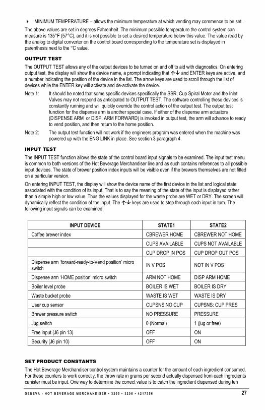
G E N E V A - H O T B E V E R A G E M E R C H A N D I S E R • 3 2 0 5 • 3 2 0 6 • 4 2 1 7 3 5 6 27
� MINIMUM TEMPERATURE – allows the minimum temperature at which vending may commence to be set.
The above values are set in degrees Fahrenheit. The minimum possible temperature the control system can measure is 135°F (57°C), and it is not possible to set a desired temperature below this value. The value read by the analog to digital converter on the control board corresponding to the temperature set is displayed in parenthesis next to the °C value.
OUTPUT TEST
The OUTPUT TEST allows any of the output devices to be turned on and off to aid with diagnostics. On entering output test, the display will show the device name, a prompt indicating that �� and ENTER keys are active, and a number indicating the position of the device in the list. The arrow keys are used to scroll through the list of devices while the ENTER key will activate and de-activate the device.
Note 1: It should be noted that some specific devices specifically the SSR, Cup Spiral Motor and the Inlet Valves may not respond as anticipated to OUTPUT TEST. The software controlling these devices is constantly running and will quickly override the control action of the output test. The output test function for the dispense arm is another special case. If either of the dispense arm actuators (DISPENSE ARM or DISP. ARM FORWARD) is invoked in output test, the arm will advance to ready to vend position, and then return to the home position.
Note 2: The output test function will not work if the engineers program was entered when the machine was powered up with the ENG LINK in place. See section 3 paragraph 4.
INPUT TEST
The INPUT TEST function allows the state of the control board input signals to be examined. The input test menu is common to both versions of the Hot Beverage Merchandiser line and as such contains references to all possible input devices. The state of brewer position index inputs will be visible even if the brewers themselves are not fitted on a particular version.
On entering INPUT TEST, the display will show the device name of the first device in the list and logical state associated with the condition of its input. That is to say the meaning of the state of the input is displayed rather than a simple high or low value. Thus the values displayed for the waste probe are WET or DRY. The screen will dynamically reflect the condition of the input. The �� keys are used to step through each input in turn. The following input signals can be examined:
INPUT DEVICE STATE1 STATE2
Coffee brewer index CBREWER HOME CBREWER NOT HOME
CUPS AVAILABLE CUPS NOT AVAILABLE
CUP DROP IN POS CUP DROP OUT POS
Dispense arm ‘forward-ready-to-Vend position’ micro switch
IN V POS NOT IN V POS
Dispense arm ‘HOME position’ micro switch ARM NOT HOME DISP ARM HOME
Boiler level probe BOILER IS WET BOILER IS DRY
Waste bucket probe WASTE IS WET WASTE IS DRY
User cup sensor CUPSNS:NO CUP CUPSNS: CUP PRES
Brewer pressure switch NO PRESSURE PRESSURE
Jug switch 0 (Normal) 1 (jug or free)
Free input (J6 pin 13) OFF ON
Security (J6 pin 10) OFF ON
SET PRODUCT CONSTANTS
The Hot Beverage Merchandiser control system maintains a counter for the amount of each ingredient consumed. For these counters to work correctly, the throw rate in grams per second actually dispensed from each ingredients canister must be input. One way to determine the correct value is to catch the ingredient dispensed during ten

28 G E N E V A - H O T B E V E R A G E M E R C H A N D I S E R • 3 2 0 5 • 3 2 0 6 • 4 2 1 7 3 5 6
vends of a particular type and then divide the weight of ingredients so dispensed by the auger run time figures set for that vend. For this to work all scale factors must be set to 100.
If the ingredient counters are not required this facility can safely be ignored. The values entered are for audit purposes only and do not affect the drink formulations or machine operation in any way.
MACHINE STATUS
Entering MACHINE STATUS provides access to the status of the following machine features.
� TEMP STATUS
� I²C HEALTH
� MEMORY USAGE*
� SOFTWARE VERSION
TEMP STATUS
The display provides information relating to the heater control circuit. A power (PWR) level value and a graphical representation of the drive waveform to the heater are displayed. The temperature reading in degrees Fahrenheit derived from the thermistor probe in the water boiler is displayed along with the analog-to-digital converter value from which the temperature was calculated in parenthesis.
I²C HEALTH
This display provides information relating to the I²C serial link between the Controller and RIO Boards. A percentage “health” reading is given, indicating the success rate of communication of the link. A reading of less than 100% may indicate the presence of electrical noise. The number of negative acknowledgements (NACKS) is also recorded.
SOFTWARE VERSION
These displays indicate the version of the software installed on the Controller Board. (Program + EPROM = Firmware). The firmware version US-WIT-XX should be quoted when seeking advice.
SET DRY VENDS
Entering SET DRY VENDS provides access to the following sub-menu:
VENDS ARE WET
All vends are dispensed with water as normal.
VENDS ARE DRY
All vends are dispensed without water. This allows ingredients to be weighed. If a multi-ingredient drink is selected, only those ingredients will be vended.
SERIAL NUMBER
Entering SERIAL NUMBER accesses the following sub-menu:
M/C SERIAL NUMBER
The machine serial number consists of 8 digits and identifies the machine on audit trails.
M/C AUDIT NUMBER
The machine audit number indicates the number of audits carried out to date.

G E N E V A - H O T B E V E R A G E M E R C H A N D I S E R • 3 2 0 5 • 3 2 0 6 • 4 2 1 7 3 5 6 29
CONFIGURE MACHINE
Entering CONFIGURE M/C provides access to the following machine configuration sub-menu headings:
GENERAL SETTINGS
The GENERAL SETTINGS menu provides access to a number of diverse parameters controlling machine operation that do not naturally group with any of the other control variables.
Parameter Possible Values
SILENT KEYS 0 (default) – Sounds a beep. 1 – Keys are silent.
TOKEN ONLY 0 (default) – Messages appropriate to coins/card system or free.
1 – Messages appropriate to token only operation.
CHIPPER/CHIPKNIP 1 (default) – Suppress credit display if just card system fitted. 0 – Normal display of credit.
FLUSH ALARM 0 (default) – Sound loud siren while flushing.
1 – Sound siren quietly while flushing.
WATER SHOT START 0 (default) – Time after a fresh coffee dispense cycle ends that a grout clearing water shot starts. Consult factory before changing.
WATER SHOT DUR 0 (default) – Duration in 1/100 seconds that the water shot described above lasts. Consult factory before changing.
EARLY WATER SHOT DUR
15 (default) – Time in 1/10 seconds for the duration of the water shot before start of second air pump sequence
BELT WARN TIME 700 (default) – Time, in 1/100 seconds, after the pressure sensor should have reported the coffee brew chamber depressurized but has not, that a “New filter belt” warning is displayed.
BELT FAULT TIME 2000 (default) – Time, in 1/100 seconds, after the pressure sensor should have reported the coffee brew chamber depressurized but has not, that a “New filter belt” fault occurs.
ROTATION LIMIT 100 (default) – Time, in 1/100 seconds, after the pressure sensor should have reported the coffee brew chamber depressurized but has not, that a flag is set to perform an extra rotation of the brewer at the end of the next brewer drink cycle.
NO BELT WARNING 1 (default) - Do not display a message on the LCD when the filter needs changing. 0 – Display a message on the LCD when the filter needs changing.
ENG MODE TIMEOUT 0 (default) – Do not automatically exit engineer’s mode. Factory default. 30 – Time in 1/10 seconds after which, if no key is pressed exit from the engineers program will commence.
MAX EXTRA CUPS 2 (default) – Number of retries at dispensing a cup before a long delay until next cup occurs to deter theft.
SIMCARD LOCATION 0 (default) J4 - Location of attached smart memory (simcard) to save configuration data. J6 - Location of attached smart memory (simcard) to save configuration data.
CURRENCY 3 (default) – Controls The symbol printed on the LCD before monetary values. € $ £ etc.
FREE INPUT 0 (default) – Disable free input on J6 pin 13. 1 – Enable free input on J6 pin 13. (Disable/Enable exist because in the event of static damage machine can continue operation if this input is ignored)
SECURITY INPUT 0 (default) – Disable security input on J6 pin 10. 1 – Enable security input on J6 pin 10. (Disable/Enable exist because in the event of static damage machine can continue operation if this input is ignored. Can be unrecoverable if set when damage has already

30 G E N E V A - H O T B E V E R A G E M E R C H A N D I S E R • 3 2 0 5 • 3 2 0 6 • 4 2 1 7 3 5 6
occurred.)
BREWER WATER CAP 950 ((default) Maximum open time for brewer water valve 1/10s second. Stops the operator putting too much water in the brewer (if it is set correctly).
BREWER EXCESS FAC 10 (default) This is a factor by which any excess water (>950) will be compensated by. i.e. the difference in the flow rates between ‘Coffee Valve’ and ‘Hot Water’ Valve.
BREWER ING. CAP 300 (default) – Maximum run time for coffee motor 1/10s second. Stops the operator putting too much coffee in the brewer (if it is set correctly).
TEMP IN CELSIUS 0 (default) = Fahrenheit
1 = Celsius
REGULAR SCALING 100 (default) – When you press for regular you get the regular drink with this scale factor applied to its settings. This is now somewhat redundant and should be left at the value (170). Changes are best done to the actual drink settings.
LARGE SCALING 100 (default) – When you press for large you get the large drink with this scale factor applied to its settings. This is now somewhat redundant and should be left at the value (170). Changes are best done to the actual drink settings.
SET MACHINE TYPE
The SET MACHINE TYPE menu provides the means by which the control board software is configured to produce the desired menu and work with the appropriate combination of brewers and whippers present in the machine. This operation must be carried out when fitting a new or replacement board.
On selecting this option, the display will change to one of the following form:
MACHINE TYPE # nn
ABCD
Where ABCDEFGHI is an abbreviated description of the machine configuration and #nn is the number of the configuration for reference purposes. The �� keys are used to scroll through the list of possible configurations. Pressing ENTER selects the new configuration. While the set up process takes place, the LCD indicates the status of the procedure. On completion, the screen reverts to the SET MACHINE TYPE menu. In order to aid understanding the following table contains an explanation of the abbreviations used.
Abbreviation Type # NO: Explanation
SFBC 00 1 Single Fresh Brew Coffee model
SFBC + CHLR 01 2 Not Used
INST 02 3 Instant Model
INST + CHLR 03 4 Not Used
INST E 04 5 Instant Economy
INST E + CHLR 05 6 Not Used
NOTE: Care should be exercised when using this option, as all previous settings will be lost.
Table 1. Machine Configuration Matrix
KEY
• = instant coffee/tea
�= Fresh brew coffee Config No.
Coffee
Whip Coffee
Tea
Decaf Coffee
Whip Decaf
Espresso
Cappuccino
Café Latte
Moccaccino
Chocolate
Hot W
ater
Vanilla Cappuccino
Toffee Cappuccino
INSTANT 3 • • • • • • • • • • • • •
SFBC 1 � � • � � � � � • • • • •

G E N E V A - H O T B E V E R A G E M E R C H A N D I S E R • 3 2 0 5 • 3 2 0 6 • 4 2 1 7 3 5 6 31
SET CASH SYSTEM
This option in this sub-menu allows the type of credit device to be selected.
Display Title Description
MDB PROTOCOL Used for all standard MDB coin changers, bill validators & cashless systems
MDB (ZIP VARIANT) Used for the European ZIP cashless system
MDB SLVE Used when the coffee machine is to be a standard MDB Universal Satellite Device i.e. payment is made in its host machine
MDB SLAVE (SM6) Used when the coffee machine is to be a MDB Universal Satellite Device where payment is made in its Snack Mart VI host machine
NO SYSTEM Used when the machine has no payment system i.e. it is set for permanent ‘FREE VEND’
DIGICARD Not Used
HARDWARE SETTINGS
This sub-menu allows some machine components to be disabled to allow limited functionality to be restored in the event of a failure. For example in the event that one of the cup sensor PCBs fails, it is possible to inform the control system that these are not fitted. Likewise in the event of a brewer failure setting the COFFEE BREWER to NO will allow any selections not reliant on the brewer to operate. While all possible system components are visible in this sub-menu, irrespective of the machine’s configuration, it is only meaningful to ENABLE components that actually exist in the machine. Thus it makes no sense to set TEA BREWER to YES on all-instant machine and indeed will result in an IO MAPPING ERROR.
Parameter Function
CUP SENSORS Enable/disable user cup sensors. Default is YES sensors fitted.
DISPENSE ARM Enable moving the dispense head. Default is YES. Can be usefully disabled only for diagnostics. The machine cannot operate with this item deselected.
TEA BREWER NOT USED
COFFEE BREWER Enable Coffee Brewer – Default for double fresh brew configurations is YES. Instant and single fresh brew configurations NO.
COLD UNIT NOT USED
NO CUP MECH Allows a machine to operate without a cup unit fitted i.e. reliant on users providing their own cups. Default is NO i.e. there is a cup mechanism fitted.
VEND DOOR YES – Default setting which enables the automatic vend door. NO – Disables the automatic vend door.
MDB CONFIG
This menu provides the means to modify parameters related to MDB peripherals connected to the machine. At present these are limited to those associated with a change giving mechanism. However as support for additional peripheral is added so additional settings will be added as appropriate.
The following table lists the sub-menus and parameters that are configurable:
Parameter Function
EXACT CHANG LIM $2 (default) – This monetary value represents the value of coins remaining in the change tubes below which the EXACT CHANGE message is displayed.
NOTE: For the audit system to work correctly it is important that all coins are inserted via the coin insert slot instead of being placed directly in the change tubes.
MDB USD ADDRESS 40 (default)
VALIDATOR ESCROW 0000000000000011 (default)

32 G E N E V A - H O T B E V E R A G E M E R C H A N D I S E R • 3 2 0 5 • 3 2 0 6 • 4 2 1 7 3 5 6
VEND BEFORE CHANGE NO (default) – Possible values are YES and NO. When set to YES, change will not be given until a vend cycle has taken place.
CHANGER MODE SINGLE VEND (default) - Possible values are SINGLE VEND and MULTI VEND. When set to MULTI VEND, change will only be paid in response to depression of the escrow lever. When set to SINGLE VEND, change will be given automatically following the vend cycle or in response to depression of the escrow lever.
MASK AUTO CONFIG Runs a procedure to carry out automatic configuration of the coin mechanism acceptance masks.
EXACT CHG BILLS 0000000000000000 (default) - Specifies which paper currency (bill or notes) the bill validator will accept. When there is no change present.
NORMAL BILLS 0000000000000011 (default) - Specifies which paper currency (bill or notes) the bill validator will accept with change present.
EXACT CHG COINS 0000000000000111 (default) - This variable controls which coins are accepted in circumstances where the exact change message would be displayed. The MDB protocol provides for up to 16 coins. For the purposes of enabling or disabling acceptance, the coins are represented by the letters A through P with A being the least value coin. The acceptance status of each coin is shown by a 1 or 0 below the corresponding letter. One indicates acceptance (1=accept) and zero indicates rejection (0=reject).
PONMLKJIHGFEDCBA
0000000000011111
Applied to a silver only changer with 5, 10, 20 & 50p coin tubes the above setting will enable acceptance of the 5, 10 & 20p coins.
NORMAL COINS 0000000000001111 (default) - This variable controls which of the coins that an attached changer is programmed to accept should actually be accepted in normal operation i.e. other than exact change mode. For the purpose of changing the coins to be accepted the procedure is the same as for Enable Coins Exact Change above.
MAX CREDIT $2.50 (default) – This monetary value defines the maximum amount that can be accepted by the mechanism.
EVA-DTS CONFIG
The EVA-DTS configuration menu provides the means to modify parameters controlling the format and method of auditing the machine. At the time of writing, the machine supports EVA-DTS audit via DDCMP protocol IRDA transceiver or Direct connect. The sub-menus of this menu are:
PREVIOUS AUDIT
On selecting this option, the LCD screen will show a screen detailing the time and date of the last audit. The layout of the screen is as shown below:
NO:XXXX ID:YYYYYY
DD/MM/YY 00:00
Where
� XXXX represents the audit number maintained by the vending machine and incremented after each audit.
� YYYYY represents the data carrier ID.
� DD/MM/YY is the date the audit took place.
� hh:mm is the time at which the audit took place.

G E N E V A - H O T B E V E R A G E M E R C H A N D I S E R • 3 2 0 5 • 3 2 0 6 • 4 2 1 7 3 5 6 33
METHOD OF AUDIT
Parameter Function
AUDIT METHOD Possible values are:
DDCMP - selects infrared or direct connect audit.
DISABLED - turns off the audit system.
DEX-UCS selects a DEX audit system.
AUDIT CONFIG
Parameter Function
SECURITY CODE Default 0 – Any data carrier may audit the machine.
The code is set by a data carrier. Once set by a carrier only a carrier with the appropriate code may access the machine.
PASS CODE Default 0 – Any data carrier may audit the machine.
The code is set by a data carrier. Once set by a carrier, only a carrier with the appropriate code may access the machine.
STATION ADDRESS Default 7 – Identifies the unit as a VMC for audit purposes.
PRODUCT CODES
EVA DTS product code for each selection can be set by the operator if they don’t like the default values.
OPERATOR CODE
Use this menu to change the operator’s access code. Also refer to PROGRAMMING on page 1.
MANAGER CODE
Use this menu to change the manager’s access code. Also refer to PROGRAMMING on page 1.
ENGINEER CODE
Use this menu to change the engineer’s access code. Also refer to PROGRAMMING on page 1.
FREE DRINK CODE
Use this menu to create a free drink code which can be used to obtain a ‘FREE’ vend without having to insert money or opening the door to use the internal keypad.
While the machine is in normal operation, press the 9 button twice on the external keypad followed by the four (4) digit code.
EDIT DRINK MAP
The Edit Drink map facility allows alternative drink recipes to be assigned to the selection buttons. For example the hot Tea selection can be substituted by a Chai Tea/Latte where there is no requirement for sugar & lightener additives. In this example the procedure is as follows:
1. Press the PROG key on the internal keypad 2. Go to the external keypad 3. Enter 4444 4. Scroll down using the ‘8’ key to menu heading EDIT DRINK MAP 5. Display shows: DRINK NUMBER 1:
COFFEE 6. Scroll up using the ‘2’ key to:
DRINK NUMBER 3: TEA
7. Press 0 (ENTER) 8. The display shows: TEA
↑↓ ENTER OR ESC 9. Scroll down using the ‘8’ key to CHAI LATTE 10. Press 0 (ENTER)

34 G E N E V A - H O T B E V E R A G E M E R C H A N D I S E R • 3 2 0 5 • 3 2 0 6 • 4 2 1 7 3 5 6
11. The display shows: DRINK NUMBER 3: CHAI LATTE
12. Press # (ESC) 13. The display shows: COMMIT CHANGES
ENTER=YES, ESC=NO 14. Press 0 (ENTER) 15. The display momentarily shows: INITIALISING DEFAULTS 16. Make any further programming changes to set prices, set cup size etc. etc.
IMPORTANT NOTES:
1. When making any changes to the drink map, all other configuration settings will default to factory values. ALWAYS MAKE ANY DRINK MAP CHANGES FIRST.
2. In addition to making the programming recipe substitution the TEA station will also require a whipper motor adding, see details on Pg XX (At foot of Chai Tea recipe chart).
CARD ACTIONS
Available only if a smart card is inserted in the smart card reader. Allows config/audit data to be saved or read from the card.
Display Title Description
INSERT CARD No card present in reader unit, a prompt to insert a card
SAVE STRINGS To download & save all the custom messages stored in the machine’s controller memory to the smart card
SAVE EVENTS To download & save all the TIMED ACTIVITIES stored in the machine’s controller memory to the smart card
SAVE PRICES To download & save all the DRINK PRICES stored in the machine’s controller memory to the smart card
SAVE CONFIG To download & save all the CONFIGURATION DATA stored in the machine’s controller memory to the smart card
SAVE MACHINE To download & save ALL the settings stored in the machine’s controller memory to the smart card
DELETE DATA To erase any previously stored data from the smart card
FORMAT CARD Erases any previously stored data and reformats the smart card ready to receive data stored in the machine’s controller memory. This is also required to format a new smart card before it can be used
LOAD STRINGS To upload & save all the DRINK PRICES stored on the smart card to the machine’s controller memory
LOAD EVENTS To upload & save all the TIMED ACTIVITIES stored on the smart card to the machine’s controller memory
LOAD PRICES To upload & save all the DRINK PRICES stored on the smart card to the machine’s controller memory
LOAD CONFIG To upload & save all the CONFIGURATION DATA stored on the smart card to the machine’s controller memory
LOAD MACHINE To upload & save ALL the machine settings stored on the smart card to the machine’s controller memory
NOTE: The ‘LOAD’ options will not appear unless there the relevant data field has already been downloaded/stored on the smart card
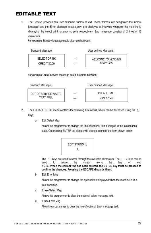
G E N E V A - H O T B E V E R A G E M E R C H A N D I S E R • 3 2 0 5 • 3 2 0 6 • 4 2 1 7 3 5 6 35
EDITABLE TEXT
1. The Geneva provides two user definable frames of text. These ‘frames’ are designated the ‘Select
Message’ and the ‘Error Message’ respectively, are displayed at intervals whenever the machine is
displaying the select drink or error screens respectively. Each message consists of 2 lines of 16
characters.
For example Standby Message could alternate between:
For example Out of Service Message could alternate between:
2. The EDITABLE TEXT menu contains the following sub menus, which can be accessed using the ↑↓
keys:
a. Edit Select Msg
Allows the programmer to change the line of optional text displayed in the ‘select drink’
state. On pressing ENTER the display will change to one of the form shown below:
The ↑↓ keys are used to scroll through the available characters. The ← → keys can be used to move the cursor along the line of text. NOTE: When the correct text has been entered, the ENTER key must be pressed to confirm the changes. Pressing the ESCAPE discards them.
b. Edit Error Msg
Allows the programmer to change the optional text displayed when the machine is in a
fault condition.
c. Erase Select Msg
Allows the programmer to clear the optional select message text.
d. Erase Error Msg
Allow the programmer to clear the line of optional Error message text.
Standard Message: User defined Message:
SELECT DRINK
CREDIT $0.00
→
← WELCOME TO VENDING
SERVICES
Standard Message: User defined Message:
OUT OF SERVICE WASTE TRAY FULL
→
←
PLEASE CALL
EXT 12345
EDIT STRING ↑↓
A

36 G E N E V A - H O T B E V E R A G E M E R C H A N D I S E R • 3 2 0 5 • 3 2 0 6 • 4 2 1 7 3 5 6
DEPRESSURIZE COFFEE BREWER
In the event that the coffee brewer remains in a pressurized state and you wish to quickly depressurize the air remaining in the chamber, there is a facility which overrides the safety pressure switch. The sequence to do this is as follows:-
With DEPRESSURISE CBR showing on the display, press ENTER (0)
The display will show either:
COFFEE BREWER NOT PRESSURISED – in which case powering the machine down/up will cycle the brewer home.
OR
IS BREWER COVER IN POSITION? – This is a safety warning, opening the brewer under pressure will squirt any hot water & coffee grounds from the cylinder base! To proceed further confirmation is required by pressing ENTER (0) a 2nd time.
After pressing the enter key the brewer motor will be switched ON for a moment which will advance the brewer to marginally release the cylinder from the filter platform seal, allowing the pressure to escape. This will be repeated until the pressure switch changes state when the sequence will stop.
To return the brewer to its home position power the machine DOWN for a few seconds then UP again.

G E N E V A - H O T B E V E R A G E M E R C H A N D I S E R • 3 2 0 5 • 3 2 0 6 • 4 2 1 7 3 5 6 37
COFFEE BREWER COFFEE BREWER OPERATION
1. The coffee brewer motor is driven a little way to clamp the base of brewing chamber to the surface of the filter platform to seal. This position is determined by the index roller switch and the 2nd dwell in the cam.
2. Water & ground coffee are dispensed into top mixing bowl of brewer unit
3. After the water delivery stops, the brew/fusion delay time starts
4. At the end of the brew/fusion time, the brewer motor drives for a moment to lift the top plunger in to seal off the top of the brewer chamber. This position is determined by the index roller switch and the 3rd dwell in the cam.
5. The 1st stage of the air pump starts and runs for the programmed duration to pressurize the chamber and push the brewed coffee out and into the coffee whipper station
6. At the end of the 1st pumping stage there is a programmed delay, this is to allow the pressure to drop and for the coffee whipper chamber to empty (i.e. not to overflow)
7. At the end of the 1st delay phase the 2nd stage air pump starts, after approximately 1 second it should be possible to hear air pass through into the coffee whipper chamber, having pushed all of the liquid out of the chamber. The remaining pumping time will dry the spent coffee grinds.
8. At the conclusion of the 2nd pumping stage there is a further programmed delay, to further assist the drying process.
9. At the conclusion of the 2nd stage pump delay the air pressure switch is checked, if there is no pressure present, the brewer motor is switched ON to drive the brewer back to its home position, in the process the brew chamber will be lifted above the level of the spent coffee grounds and the filter belt is driven to remove/discard the grounds. However, if air pressure is still present a waiting/time-out period is started, the pressure switch is then checked at 1 second intervals up to 20 seconds. This is to prevent the chamber opening under pressure and making a mess. If the pressure subsides at any point up to the 20 seconds, the brewer motor will be switched ON to drive home as normal. If air pressure is still present after 20 seconds, then the coffee brewer is put out of action, and COFFEE BREWER FAULT is displayed. A ‘BREWER FAULT’ condition can be reset by switching the machine OFF and back ON. However, if the cause of the pressure remaining is not remedied, then the fault condition will be reinstated at some earl point.

38 G E N E V A - H O T B E V E R A G E M E R C H A N D I S E R • 3 2 0 5 • 3 2 0 6 • 4 2 1 7 3 5 6
TROUBLESHOOTING GUIDELINES
Problem Symptom Remedy
The brewer fault condition has been triggered by a 20 second time-out, indicating that the air pressure inside the brewer cylinder is remaining after the vend: 1. Filter Belt Blocked – Replace (p/n 4215265.001) 2. Coffee Grinds are too fine, replace with 17 grind or greater
COFFEE BREWER FAULT displayed – Upon power-up the coffee brewer completes one cycle as normal and stops in home position
The air pressure switch is faulty and is not opening (normally operates to close switch at 4 psi) – Replace switch
No Coffee
COFFEE BREWER FAULT displayed – Upon power-up the coffee brewer runs continuously for approximately 3 ¼ cycles and then stops off the home position
1. The brewer index switch has failed - replace 2. The signal is not present at J6 of the RIO
board – Check wiring/terminals and rectify
Check that the brewer carriage is pushed fully back and locked into position. Check that belt is being driven correctly by using the ‘ADVANCE COFFEE BREWER’ key on the internal keypad
Coffee grinds are not being completely washed through the top mixing bowl. Flush to clear, then; 1. Check/adjust all coffee recipes to be sure the
top chamber is rinsed clear 2. Is there a sufficient water swirl to clear the
coffee –adjust or replace valve 3. If the water is unable to pass into the lower
chamber quickly, then adjust the top seal in a downward direction by one half of a turn on the thread
The filter belt is slipping – 1. Check that the belt tension bar is not in the
‘relaxed’ position. 2. If the belt is tensioned and is still slipping,
replace the filter belt (pn 4215265.001) 3. See section below related to wet/sloppy grinds
No Coffee Coffee Brewer is stalled and is full of coffee grinds
Coffee throw is too high, spent coffee grinds are left inside chamber when belt moves to clear, reduce throws to less than 13gms
Coffee belt is worn/choked, replace belt (Blue stitching pn 4215265.001 – 55 Micron)
Seal at base of brewing cylinder is damaged causing leakage – replace cylinder
Seal in filter platform damaged or missing causing leakage – replace seal/platform
Short level of Coffee in cup or Coffee Grounds in drink
The spent coffee grinds are wet/sloppy
The air pump has failed, or is failing intermittently, no pressure being produced – replace air pump (check with end of little finger to see if pump is producing pressure at the bulkhead connection, using the OUTPUT TEST to run the pump)

G E N E V A - H O T B E V E R A G E M E R C H A N D I S E R • 3 2 0 5 • 3 2 0 6 • 4 2 1 7 3 5 6 39
Problem Symptom Remedy
The air pump is starting to fail, or is failing intermittently, insufficient pressure is being produced – replace air pump (check with end of little finger to see if pump is producing pressure at the bulkhead connection, using the OUTPUT TEST to run the pump)
The water and grounds are not passing from the top mixing bowl into the main brewing chamber before it is sealed-off at the top, hence when the chamber lifts at the end of the cycle the remaining water gushes from the cylinder. Note: This can be intermittent. Relax the sealing rod adjustment by ONE TURN ONLY to lower the seal position thus allowing the Water/Grounds to pass through more easily.
One of the air carrying tubes have come adrift – replace offending tube (check with end of little finger to see if pump is producing pressure at the bulkhead connection, use OUTPUT TEST to run the pump)
Airway into cylinder is blocked with coffee grinds or similar, remove cylinder and check/clear airway with paper clip. Invert cylinder and fill with water and check that water flows freely from air inlet port.
When the chamber lifts towards the end of the vend cycle, water & coffee grinds come gushing out
The rubber bellows joining the brewing cylinder sections is spilt causing leakage. Invert cylinder and fill with water to check for leaks whilst working bellows – replace cylinder assembly
Coffee canister empty, therefore water coming through too quickly – Fill canister
Short level of Coffee
Water coming out of whipper funnel cap like a fountain/whale blow
Coffee whipper impellor to far forward on shaft blocking outlet due to being loose or not fitted correctly (flat not aligned) – replace impellor or fit correctly

40 G E N E V A - H O T B E V E R A G E M E R C H A N D I S E R • 3 2 0 5 • 3 2 0 6 • 4 2 1 7 3 5 6
REPLACEMENT CONTROL BOARD SETUP The FMCU Control Board (p/n 4214454) used in the Hot Beverage Merchandiser utilizes static sensitive
components. Precautions for handling static sensitive devices should be observed when handling this item.
The Hot Beverage Merchandiser control board is programmable on two levels. At the lowest level the board’s Flash memory (firmware), can be reprogrammed to enable a wide range of different machines to be controlled. This level of programming requires a PC and special interface equipment and is essentially a factory/main base activity. The firmware programmed into a board can be read from the label fitted to the component side of the board or if placed in a functioning machine using the Machine Status menu. Please refer to section 3 paragraph K.
The Hot Beverage Merchandiser software versions will typically be of the form “US_WIT_XX”. “US_WIT" denotes the program and XX is a number defining the version. New versions will be generated to support customer specific configurations and behaviors. It is therefore important to check that the firmware programmed into a board is appropriate to the machine to which it is to be fitted, as older version may not support a particular machine type.
The second level of programming involves setting up the board to operate the correct predefined menu configuration for the machine to which it is fitted. This section details the procedure to achieve this:
1. Switch OFF machine
2. Place shorting jack across the ‘ENG LINK’
3. Power-up, service mode is entered automatically (‘INGREDIENT TIMES’ displayed)
4. Press 2 (UP) or 8 (DOWN) on front keypad board repeatedly to reach “CONFIG MC”
5. Press 0 (ENTER) – “GENERAL SETTINGS”
6. Press 2 (DOWN) repeatedly to reach “SET MACHINE TYPE”
7. Press 0
8. Select machine type required by pressing 2 (UP) or 8 (DOWN): SFBC :1 (FACTORY DEFAULT) SFBC + CHLR :2 INST :3 INST + CHLR :4 INST E :5 INST E + CHLR :6
9. Press 0 (ENTER) to confirm and wait for reinitializing process to complete
10. Select CUP SIZE required by pressing 2 (UP) or 8 (DOWN): 7oz 8¼oz (FACTORY DEFAULT) 9oz 12oz
11. Press 0 (ENTER) to confirm
12. Press # repeatedly until “REMOVE ENGINEERS LINK” is shown on display
13. Switch OFF and remove the shorting jack and park on a single pin
14. Board is now initialized.
15. Re-enter programming mode and set the time & date, prices etc.

NOTES

The contents of this publication are presented for informational purposes only, and while every effort has been made to ensure their accuracy, they are not to be construed as warranties or guarantees, express or implied, regarding the products or services described herein or their use or applicability. We reserve the right to modify or improve the designs or specifications of such products at any time without notice.
VendNet™
165 North 10th Street Waukee, Iowa 50263
United States of America
USA & Canada International
Service (800) 833-4411
Parts (888) 259-9965 (515) 274-3641
Email [email protected]
Web Site www.vendnetusa.com
4214803A.DOC