geometric analysis of injection-molded polymer gears rapid
TRANSCRIPT

56 2021, 66, nr 1
Geometric analysis of injection-molded polymer gears (Rapid communication)
Jadwiga Pisula1) (orcid id 0000-0002-3197-9528)
DOI: dx.doi.org/10.14314/polimery.2021.1.8
Abstract: Properties of polymer gears were tested using coordinate measurement methods. This study is a follow-up to research on geometric accuracy of gears manufactured by injection molding. Spur gears were measured on a coordinate measuring machine running the GINA software by Klingelnberg. Measurement results were output in the form of measurement sheets which included values required in the DIN 3962 standard. The article also analyses the topography of test gear teeth. The topography was presented for a single tooth of the gear and determined on the basis of the measurements of 9 profiles distributed evenly over a specific profile assessment interval (interval Lα defined in the standard) and 7 tooth traces located within a relevant tooth trace assessment interval (interval Lβ defined in the stan-dard). All gears tested in this study were placed outside accuracy class 12.Keywords: geometric accuracy, gear topography, molding shrinkage, polymer gears.
Analiza geometryczna polimerowych kół zębatych otrzymanych metodą wtryskiwaniaStreszczenie: Właściwości użytkowe polimerowych kół zębatych badano z zastosowaniem współrzęd-nościowych metod pomiarowych. Opracowanie stanowi kontynuację prac nad dokładnością geometrii kół wytwarzanych metodą wtryskiwania. Do pomiaru kół zębatych walcowych użyto współrzędno-ściowej maszyny pomiarowej wyposażonej w specjalistyczne oprogramowanie o nazwie GINA fir-my Klingelnberg. Wyniki pomiaru otrzymywano w postaci arkuszy pomiarowych uwzględniających wartości z normy DIN 3962. Analizowano również topografię zębów kół badawczych. Przedstawiono topografię jednego zęba koła, określoną na podstawie pomiaru 9 zarysów równomiernie rozmieszczo-nych na odpowiednim odcinku oceny zarysu (odcinku Lα definiowanym wg normy) i 7 liniach zęba umiejscowionych na odpowiednim odcinku oceny linii zęba (odcinku Lβ definiowanym wg normy). Wszystkie badane koła znalazły się poza 12 klasą dokładności.Słowa kluczowe: dokładność geometryczna, topografia kół zębatych, skurcz przetwórczy, polimerowe koła zębate.
The recent years have seen rapid development of polymer materials, which are applied in manufactur-ing machine parts, including parts of gear-based drive systems. Such parts are manufactured on a large scale from structural polymers in a PA (polyamide), POM (polyoxymethylene), PC (polycarbonate) or ABS (acrylo-nitrile butadiene styrene) matrix using plastic working (injection molding) [1, 2] or subtractive manufacturing methods (machining, electrical discharge machining) on numerically-controlled machine tools (milling with the use of a hobbing machine, slot cutter, profile cutter,
CNC-milling by cutting out tooth profiles) and electric discharge machines [3–5]. The injection molding tech-nology allows us to obtain even several hundreds pieces in a single injection cycle, depending on the number of cavities in the mold (the greater number of cavities, the more cost-effective the production). Unfortunately, vari-ous undesirable phenomena (e.g. a rapid pressure drop in the mold) occurring in the injection molding process may cause defects in the molded pieces. Such defects include sink marks, air pockets, warping or the deterio-ration of dimensional accuracy. The geometric accuracy of the manufactured gears affects the operation of the gears in terms of uniformity of motion transmission and its strength, especially in terms of fatigue strength and wear. The present study is a continuation of research con-ducted in the Department of Machine Design at Rzeszów University of Technology on the geometric accuracy of polymer gears [1, 2, 6], which are subjected to fatigue tests
1) Rzeszow University of Technology, Department of Mecha-nical Engineering, Faculty of Mechanical Engineering and Aeronautics, al. Powstańców Warszawy 8, 35-959 Rzeszów, Po-land. e-mail: [email protected]

POLIMERY 2021, 66, nr 1 57
in order to determine the mechanical properties of the gears made by various technologies.
EXPERIMENTAL PART
Materials
– Zytel PLS95G50DH2 BK261(PA66+45%FG, polyamide 66 + 45 wt % of fiber glass) by DuPont, referred to as P1;
– Zytel HTN51G35HSL NC010 (PPA6+35%FG, perfor-mance polyamide 6 + 35 wt % of fiber glass) by DuPont, referred to as P2;
– Zytel PLS95G35DH1 BK549 (PA66+35%FG) by DuPont, referred to as P3;
– Zytel 101L NC010 (PA66) by DuPont, referred to as P4;
– Tarnamid T-27 NATUR (PA6) by Azoty Tarnów, referred to as P5;
– Grivory HTV-3H1 BLACK 9205 (PPA6+30%FG) by ES CHEMIE AG, referred to as P6.
Molding method used in the study
Molded pieces were made using the injection molding technology on an injection molding machine by ENGEL. Before injection, the materials were dried in order to remove humidity which may cause defects in molded pieces in the process and lead to erroneous results. The exact parameters of the injection process constitute pro-prietary information. Table 1 shows parameters of the drying process as well as injection and mold tempera-tures.
Key specifications of test gears
The selected geometric data of the basic gears are given in Table 2.T a b l e 2. Parameters of gears used in geometric accuracy tests
Parameter Driving gear Driven gear
Number of teeth 17 25
Pressure angle, deg 20
Module, mm 3
Centre distance, mm 63.292
Face width, mm 17 15
Outside diameter, mm 56.990 81.584
Tooth thickness, mm 4.712 4.717
Geometric accuracy measurement of molded gears
Gear measurements were made on coordinate mea-suring machine P40 by Klingelnberg at the Gear Testing Laboratory at the Faculty of Machine Engineering and Aeronautics, Rzeszów University of Technology. GINA, a specialist software for spur gear measurement by Klingelnberg, was applied to make measurements and generate results in the form of measurement sheets. Measurements were taken in laboratory conditions at the temperature from 18°C to 20°C and low constant humid-ity. A rod with two ruby tips of diameter 1.5 mm each was used, offering shortest possible reach (Fig. 1). During the measurement, two reference bases of choice were used (cylindrical and face surface). The gears were placed in a three-jaw chuck in the centre point of the rotary table of the P40 coordinate measuring machine.
T a b l e 1. Plastic drying and injection process parameters
Polymer material P1 P2 P3 P4 P5 P6Drying time, h 2–4 2–4 2–4 2–4 2–6 6–8Drying temperature, °C 80 80 80 80 80 100Permissible humidity, % 0.1 0.2 0.2 0.2 0.12 0.1Injection min/max temperature, °C 230–270 280–300 280–290 285–305 280–300 320–330Mold min/max temperature, °C 60–80 50–90 70–120 70–120 80–120 140–180
Fig. 1. Overview of the test station
58 POLIMERY 2021, 66, nr 1
RESULTS AND DISCUSSION
Measurements on the P40 coordinate measuring machine were performed in order to determine the geo-metric accuracy of test gears. Sample results from mea-surement sheets are shown in Figs. 2–4 for a selected test gear made from P5. Measurement sheets contain param-eters describing tooth profile and tooth trace geometry, pitch and tooth thickness. Tooth topography, defined by the size of profiles and tooth traces distributed evenly over the tooth width and height, was also assessed. The results of the analysis of the geometry of polymer gears are shown in Table 3.
Parameters contained in Table 3 describe tooth pro-file and trace geometry, pitch and tooth thickness. These include: fHα– profile slope deviation, Fα – total profile deviation, ffα– profile form deviation, fHβ– tooth trace slope deviation, Fβ – total tooth trace deviation, ffβ – tooth trace form deviation, fpmax – max. single pitch deviation, fumax – max. tooth spacing (pitch) error, Fp – total cumula-tive pitch deviation, Fpz/8 – cumulative pitch-span devia-tion for eight teeth, Fr – runout error, Rs – tooth thickness variation.
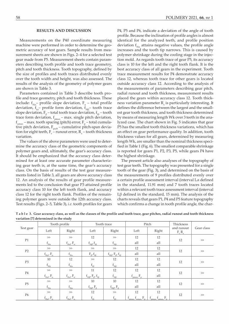
The values of the above parameters were used to deter-mine the accuracy class of the geometric components of polymer gears and, ultimately, the gear’s accuracy class. It should be emphasized that the accuracy class deter-mined for at least one accurate parameter characteriz-ing gear teeth is, at the same time, the gear’s accuracy class. On the basis of results of the test gear measure-ments listed in Table 3, all gears are above accuracy class 12. An analysis of the results of gear profile measure-ments led to the conclusion that gear P3 attained profile accuracy class 10 for the left tooth flank, and accuracy class 12 for the right tooth flank. Profiles of the remain-ing polymer gears were outside the 12th accuracy class. Test results (Figs. 2–5, Table 3), i.e. tooth profiles for gears
P4, P5 and P6, indicate a deviation of the angle of tooth profile. Because the inclination of profile angles is almost identical for the analyzed teeth, and profile position deviation fHα attains negative values, the profile angle increases and the tooth tip narrows. This is caused by polymer shrinkage during the cooling stage in the injec-tion mold. As regards tooth trace of gear P5, its accuracy class is 10 for the left and the right tooth flank. It is the best accuracy class of all gears in the experiment. Tooth trace measurement results for P4 demonstrate accuracy class 12, whereas tooth trace for other gears is located outside accuracy class 12. According to the analysis of the measurements of parameters describing gear pitch, radial runout and tooth thickness, measurement results placed the gears within accuracy class 12. Tooth thick-ness variation parameter Rs is particularly interesting. It defines the difference between the largest and the small-est gear tooth thickness, and tooth thickness determined by means of measuring length Wk over 3 teeth in the ana-lyzed case. The chart shown in Fig. 5 indicates that gear P5 has the smallest tooth thickness variations, which has an effect on gear performance quality. In addition, tooth thickness values for all gears, determined by measuring length Wk, are smaller than the nominal thickness speci-fied in Table 1 (Fig. 6). The smallest comparable shrinkage is reported for gears P1, P2, P3, P5, while gears P4 have the highest shrinkage.
The present article also analyses of the topography of test gear teeth. The topography was presented for a single tooth of the gear (Fig. 3), and determined on the basis of the measurements of 9 profiles distributed evenly over a certain profile assessment interval (interval Lα defined in the standard, 11.91 mm) and 7 tooth traces located within a relevant tooth trace assessment interval (interval Lβ defined in the standard, 15 mm). The analysis of the charts reveals that gears P1, P4 and P5 feature topography which confirms a change in tooth profile angle, the char-
T a b l e 3. Gear accuracy class, as well as the classes of the profile and tooth trace, gear pitches, radial runout and tooth thickness variation [7] determined in the study
Test gearTooth profile Tooth trace Pitch Thickness
and runout Fr, Rs
Gear classLeft Right Left Right Left Right
P1>> >> 12 >> 12 12
12 >>fHα fHα, Fα fHβ, ffβ fHβ all all
P2>> >> >> >> 12 12
12 >>fHα, Fα fHα Fβ, ffβ fHβ, Fβ, ffβ all all
P310 12 >> 12 12 12
12 >>fHα fHα ffβ fHβ all all
P4>> >> 11 12 12 12
12 >>fHα, Fα fHα, Fα fHβ, Fβ, ffβ fHβ fpmax, Fp all
P5>> >> 10 10 12 12
12 >>fHα fHα fHβ, Fβ fHβ, Fβ all all
P6>> >> 12 >> 12 12
12 >>fHα, Fα fHα, Fα ffβ ffβ fpmax, fumax, Fp fpmax, fumax, Fp

POLIMERY 2021, 66, nr 1 59
Fig. 2. P5 pinion (z17): tooth profile and tooth trace measurement results

60 POLIMERY 2021, 66, nr 1
Fig. 3. P5 pinion (z17): tooth topography measurement results

POLIMERY 2021, 66, nr 1 61
Fig. 4. P5 pinion (z17): pitch and tooth thickness measurement results

62 POLIMERY 2021, 66, nr 1
acter of which is invariable on tooth flanks. Topographies of the teeth of all gears contain concavities. Gear P6 has a clear concavity on the right flank of the tooth (approx. 50 mm), gears P1 and P2 have a clear concavity on the left flank of the tooth, while gear P3 has an even concavity on both tooth flanks.
CONCLUSIONS
On the basis of the results we may conclude that poly-mer gear P5 returned the best results, although all gears tested in this study were placed outside accuracy class 12. In other cases, geometry tests of gear surfaces showed much inferior results. This may suggest either that injec-tion parameters were poorly optimized or that the cool-ing time was too short. Unfortunately, the gears require additional processing by means of machining e.g. by gear shaving.
REFERENCES
[1] Pisula J.: Polimery 2019, 64, 353. http://dx.doi.org/10.14314/polimery.2019.5.6[2] Budzik G., Dziubek T., Zaborniak M.: „Analiza
dokładności geometrycznej prototypów kół zęba-
tych z zastosowaniem współrzędnościowej tech-niki pomiarowej” in „Określenie chwilowego śladu styku przekładni zębatych z zastosowaniem metod szybkiego prototypowania”, Oficyna Wydawnicza Politechniki Rzeszowskiej, 2011, pp. 131–148, ISBN 978-83-7199-686-3.
[3] Thirugnanam A., Sathish J., Rakesh L.: Middle East Journal of Scientific Research 2014, 20, 966.
http://dx.doi.org/10.5829/idosi.mejsr.2014.20.08.114144[4] Mao K., Li W., Hooke C., Walton D.: Wear 2009, 267,
639. https://doi.org/10.1016/j.wear.2008.10.005[5] Mao K., Langlois P., Hu Z. et al.: Wear 2015, 332-333,
822. https://doi.org/10.1016/j.wear.2015.01.084[6] Sobolak M., Połowniak P., Cieplak M. et al.: Polimery
2020, 65, 563. http://dx.doi.org/10.14314/polimery.2020.7.9[7] DIN 3962-1,2: 1978: Tolerances for cylindrical gear
teeth. Part 1: Tolerances for deviations of individual parameters. Part 2: Tolerances for tooth trace devia-tion
Received 28 VIII 2020.
P1
415
333 330
233
163 178
P2
Vari
atio
n of
toot
h th
ickn
ess,
µm
P3Symbol of sample
P4 P5 P6
500
450
400
350
300
250
200
150
100
50
0
Fig. 5. A chart showing the variation of test gear tooth thick-ness (Rs)
23.0
22.8
22.6
22.4
max value
22.855
22.729
22.628
22.716
22.609
22.701
22.597
22.719
22.6122.681
22.592
22.247
22.18
22.855 22.855 22.855 22.855 22.855
min valuenominal value
22.2
22.0
21.8P1 P2 P3 P4 P5 P6
Base
tang
ent l
engt
h (W
k), m
mSymbol of sample
Fig. 6. A chart presenting test gear tooth fluctuations provided by means of measuring length (Wk)