geophysical exploration for groundwater in the lusaka ...calegg.com/lusaka_groundwater.pdf ·...
TRANSCRIPT

J. Geophys. 40, 97-112, 1974
Geophysical Exploration for Groundwater in the Lusaka District, Republic of Zambia
K. D. Topfer University of Zambia, School of Natural SciencesC. A. Legg Geological Survey Department, Lusaka
Received September 13, 1973
Abstract. The value of geophysical techniques (geoelectric-seismic refraction techniques) in the field of groundwater exploration in the Lusaka District, Republic of Zambia, is discussed and documented by some case histories. Aquifers in schists, limestones, quartzites, at schist-limestone contacts, and at the margins of intrusive bodies were investigated. Geophysical results are compared with the results of drilling and the borehole yields.
Key words: Schlumberger Soundings — Seismic Refraction — Groundwater Exploration. -
1. IntroductionLusaka, the capital of the Republic of Zambia, is situated on the Zambian plateau, some 1280 meters above sea level. The average rainfall is 813 millimetres. Its climate can be divided into three seasons: a rainy season from November to April, a dry season from May to August, and a hotseason from September to October. Monthly figures of temperature, relative humidity and rainfall are given in Fig. 1 (Frost, 1971). Much of Lusaka’s water supply is drawn from groundwater aquifers, although recently additional supplies have been obtained from the Kafue river, 50 kmsouth of Lusaka.
Many small plots and farms scattered-around Lusaka District produce vegetables and other essential food stuffs for the City and depend on a reliable groundwater supply for irrigation purposes. Geophysical exploration methods, although somewhat limited due to the small size of the plots (1-50 acres) have proved to be an economical tool in borehole siting.
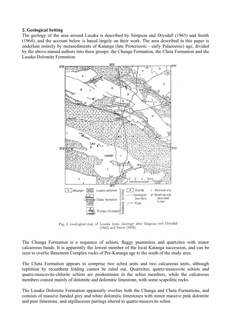
2. Geological SettingThe geology of the area around Lusaka is described by Simpson and Drysdall (1963) and Smith (1964), and the account below is based largely on their work. The area described in this paper is underlain entirely by metasediments of Katanga (late Proterozoic - early Palaeozoic) age, divided by the above-named authors into three groups: the Chunga Formation, the Cheta Formation and the Lusaka Dolomite Formation.
The Chunga Formation is a sequence of schists, flaggy psammites and quartzites with minor calcareous bands. It is apparently the lowest member of the local Katanga succession, and can be seen to overlie Basement Complex rocks of Pre-Katanga age to the south of the study area.
The Cheta Formation appears to comprise two schist units and two calcareous units, although repitition by recumbent folding cannot be ruled out. Quartzites, quartz-muscovite schists and quartz-muscovite-chlorite schists are predominant in the schist members, while the calcareous members consist mainly of dolomite and dolomitic limestone, with some scapolitic rocks.
The Lusaka Dolomite Formation apparently overlies both the Chunga and Cheta Formations, and consists of massive banded grey and white dolomitic limestones with minor massive pink dolomite and pure limestone, and argillaceous partings altered to quartz-muscovite schist.

To the NW of Lusaka, folded metasediments of the Chunga and Cheta Formations are apparently intruded by an elongate boss of granite, now foliated, while the Cheta Formation is intruded by a number of small gabbroic plugs, now marginally affected by regional metamorphism.
The Katanga rocks have been affected by at least two phase of folding. The first phase resulted in tight recumbent shear-folds, a strong axial-plane clearage in schistose rocks and tectonic banding in carbonates. Re-folding tends to obscure the true stratigraphic sequence, and is largely responsiblefor the observed outcrop pattern. Faulting is locally important, most faults separating schist from limestone. A major post-Karroo (post-Permo-Carboniferous) fault defines the northern margin of the Kafue fault through in the south of the area.
Superficial deposits are often thick, and are normally characteristic of the underlying rock-type. Dolomitic limestones are commonly blanketed by pisolitic laterite, which can infill deep solution hollows in the Karst-type surface. Schists are covered by up to 30 m of residual weathered material, commonly a sandy clay. Quartzites weather to give a quartzy sand of varying clay content.
3.

Geophysical Methods UsedGeoelectric resistivity and seismic refraction methods have been applied in the investigation of groundwater aquifers in the Lusaka District.
3.1. Resistivity MeasurementsGeoelectric soundings, using the Schlumberger array, are used by the senior author. The apparent specific resistivity is measured as function of half the current electrode separation (AB/2) and the resulting “sounding curve” interpreted by matching with “master curves”.
Although direct interpretation of field curves is possible since the introduction of large computers (Kunetz and Rocroi, 1970), it becomes un-economical for small-scale surveys of the kind described here. A “Compucorp” desk computer is used only to study the “principle of equivalence”, applying the “method of decomposition” (Kunetz, 1966), whereas the interpretation of field curves is done applying Hummel’s method as introduced by Ebert (1943).
This is sufficient in most cases and errors as to depth determinations are within 15%, considered to be a tolerable limit. In areas, where sounding curves are distorted due to lateral effects (i. e. limestone under shallow soil cover), so that an interpretation using master curves calculated for nearhorizontal layer problems becomes more or less meaningless, “iso-resistivity maps” are constructed for several current electrode separations AB. Thus resistivity lows and highs are readily shown up for different depths of investigation. Only qualitative interpretation is possible and generally larger areas of low apparent spec. resistivity are most promising for a good borehole site (see also chapter 4.2). Supplementary seismic refraction measurements across zones of low spec. resistivity are very useful] for the final siting of a borehole.
3.2. Seismic Refraction MeasurementsSeismic refraction methods as supplement to geoelectric resistivity measurements proved to provide additional information only in areas of limestone, quartzite and sediments of Karroo age, near Kafue, southwest of Lusaka. A continuous profiling technique (Barthelmes, 1946) is exclusively used, allowing a detailed study of bedrock velocities and bedrock irregularities such as solution hollows and fractured zones in limestone. Interpretation is based on the “plus-minus method” (Hagedorn, 1959), and done with the help of a desk computer.
A “Huntec FS 3” seismic equipment is employed, using a 5 kg hammer as energy source (Paterson, 1968). This equipment proved to be sufficient for geophone lines of up to 120 meters. The geophone array remains fixed and the hammer source is moved in 2 meter intervals for the first 20 meters and thereafter in 5 meter intervals. Every “shot” is repeated three times so that signals can bereadily distinguished from noise.
3.3. Geophysical ParametersGeophysical parameters in the area of investigation vary over a wide range: from 7-12 ohmmeters (mudstone of Karroo age) to several ten thousands of ohmmeters (solid, crystallized limestone of Katanga age) and 180 m/sec (dry loose top soil) to 6400 m/sec (solid, crystallized limestone).
In the Lusaka District, the groundwater potential of a water bearing horizon cannot be estimated from its true specific resistivity, as it can be done for certain sediments, like pure gravel, sand etc. (Topfer, 1972). This is partly because of the clay content in weathered rock and partly because of the characters of the groundwater aquifers themselves, i. e. fissures, cavities in limestone. A collection of geophysical parameters or rocks, as encountered in the Lusaka District, is given in Table 1.

Table 1Rock Type Location Spec. Remtivity Compr. Velocity
weath. schist Lusaka West 8-100 Qm 800-2000 m/secsolid schist Lusaka West 100-900 3000fract. limestone Lusaka West 140-300 2000solid limestone Lusaka West 500 3000-4500ctyst. limestone Lusaka West 10,000 5000-6200quartzites Lusaka North 1600—8000 3300shales Unza, Lusaka 20-50 600-1000sandstone(Karroo) Kafue 200mudstone (Karroo) Kafue 8-12
4. Examples of Groundwater Exploration in Different Aquifers:A few case histories, which are typical for the area of investigation, will give an overall idea of geophysical groundwater exploration in schists, limestones, quartzites, schist-limestone contacts and contacts between schist and intrusive bodies. The few examples were selected from a numberof surveys undertaken in the Lusaka District, Fig. 2.
For economic reasons and because of the small size of plots usually encountered, a geophysical groundwater survey is generally restricted to 5-12 geoelectric soundings (ABm.x = 200-400 meters) and/or 4 refraction reverse shots (smax=120 meters). Thus a depth of investigation of approximately 20-60 meters is achieved, depending on the contrast of geophysical parameters in the ground. Near surface layers of relatively high conductivity screen the current flow and limit therefore the depth of investigation (Kunetz, 1966).
The achieved depth of investigation is in reasonable agreement with economic depths of boreholes for water supply in the Lusaka area.
4.1. Geophysical Investigations in Schists (Phyllites, Muscovite Schists, Biotite Schists, Quartz Schists)In many areas, psammites and finer grained schists alternate and weathering may occur down to 30 meters, in some cases 50 meters. Minor groundwater supply can often be encountered at the interface of alternate layers within the zone of weathering. These discontinuities are only sometimes shown up in geoelectric sounding curves (see Fig. 4, sounding no. 2). Normally the alternating layers are too thin and the resistivity contrast too small, to be detected individually. Thus the whole zone of weathering is usually shown up geoelectrically as a single macro-anisotropic layer with average resistivities between 8 and 100 ohmmeters. The schists themselves are sometimes regularlybanded so that micro-anisotropy applies as well. Because of micro- and macro anisotropy, generally only an “apparent thickness” of the weathered zone can be obtained from geoelectric sounding curves (Maillet, 1947).
The main groundwater supply in schists comes mostly from the lowest zone of decomposition, i. e. the interface between weathered and more solid schist, or from the very topmost meters of solid schist, the latter being indicated by spec. resistivities between 100 and 900 ohmmeters. Sounding curves obtained in schist are generally very “smooth” and of type H, QH or KH (Orellana and Mooney, 1966). A selection of typical sounding curves obtained in schist areas is shown in Fig. 3.
Although the sounding curves are not normally distorted, their interpretation often becomes difficult and is seldom unique because of anisotropy, poor distinction between curve types (i. e. curve 3 of type QH in Fig. 4 might have been taken for a curve of type H), and the principle of equivalence (Koefoed, 1969). Surprisingly however, errors in depth determination to solid schist are generally
negligible or small. Schists are often uniform over large areas. The aim of geoelectric investigations in groundwater exploration in these areas is to determine the depth to solid schist and boreholes are sited where the weathering is thickest.
Seismic refraction measurements provide little information additional to that already obtained from resistivity measurements.
The interpretative cross-section of a part of a profile of geoelectrical soundings, as measured in Lusaka West (site no. l) is shown in Fig. 4. Two layers of soil, the uppermost having spec. resistivities of approximately 60 ohmmeters and the lower of about 160 ohmmeters, overlie decomposed schist with spec. resistivities between 60 and 100 ohmmeters. The solid schist is shown to have resistivities between 700 and 850 ohmmeters. Sounding no. 2 had been selected for a borehole site for two reasons: firstly the zone of weathering is thickest and secondly the weathered schist appears to be divided into two parts with average spec. resistivities of 60 and 150 ohmmeters, the lower part being more permeable because of a lower clay content. A borehole was drilled down to 52 meters (on the request of the owner of the property) and water was struck at 12 meters (the boundary between the two kinds of weathered schist) the main supply being at 18-24 meters (within the coarser weathered schist). Pump tests recorded a yield of 0.9 l/sec (700 gal/h).
4.2. Geophysical Investigations in Limestones (Limestones, Dolomitic Limestones, Dolomites)Dolomitic limestones of Katanga age play the major role in ground- water supply in the Lusaka District. In fact, Lusaka City obtains its main water supply from a few large and medium diameter boreholes drilled in collapse breccias in limestone. Yields of up to 157 l/sec (3 X 10⁶ gal/day) are reported (Simpson, Drysdall and Lambert, 1963). These large yields are drawn from large underground drainage systems in enlarged solution fissures, caverns and collapse breccias. Yields naturally become smaller in less soluble limestone where fissuring is less marked. Solution hollows in the surface of limestone filled with soil and laterite are also often good aquifers and are especially suitable for wells.
Geophysical exploration for groundwater in limestones is thus aimed at locating zones of fissuring and/or solution hollows at the surface. In many areas around Lusaka, the soil cover above limestone is very shallow or absent.
Therefore, and also because “horizontal layering” in a geoelectric sense is absent, sounding curves are generally distorted to a great extent and the normal interpretation procedure (comparison with master curves) becomes more or less doubtful. Sounding curves, measured for example only 50 meters apart from each other along a profile, Fig. 5, as obtained during a survey in Lusaka West (site no. 2), do not show even an uniform curve type. However, the total longitudinal conductance of all “layers” above the high resistive solid lirnestone can often be estimated from the final branch of the sounding curve (45° or near 45° slope) (Kunetz, 1966).
Sounding curves become smooth in areas where the soil cover is thick, or where large solution hollows exist and the thickness of overburden can be determined. The authors undertake geoelectric soundings nevertheless, trying to cover the whole area of interest as densely as is economically feasible. In most cases, iso-resistivity maps for different current electrode spacings are drawn thereafter. These maps can be interpreted qualitatively only, i.e. zones of low resistivity are more or less precisely located. Resistivity lows for small current electrode‘ spacings (small depth of investigation) commonly indicate thick soil cover (i. e. infilled near surface solution hollows) andresistivity lows for large electrode separation are thought to indicate zones of fissuring. It becomes obvious that resistivity mapping techniques with one constant electrode array only, are doubtful in their value.

Boreholes are usually sited where resistivity lows are shown up in iso-resistivity maps for several electrode spacings. An example is taken from a survey undertaken in Lusaka West (site no. 2). An existing shallow borehole provides little water from the surface of solid rock beneath a cover of limestone boulders and laterite. Iso-resistivity maps were drawn for several electrode separations, those for AB=60 meters and AB=150 meters are shown in Fig. 6 and Fig. 7, respectively.
The main feature apparent from the maps are a large well-defined zone of high resistivity (5000 ohm-meters) and a small zone of relatively low resistivity (800-1500 0hm meters) close to the western boundary of the plot.
A borehole was drilled in the resistivity low and water was struck at 12 meters, the main supply being between 18 and 28 meters. The borehole yields 4.2 litres.sec (3300 gal/hr).
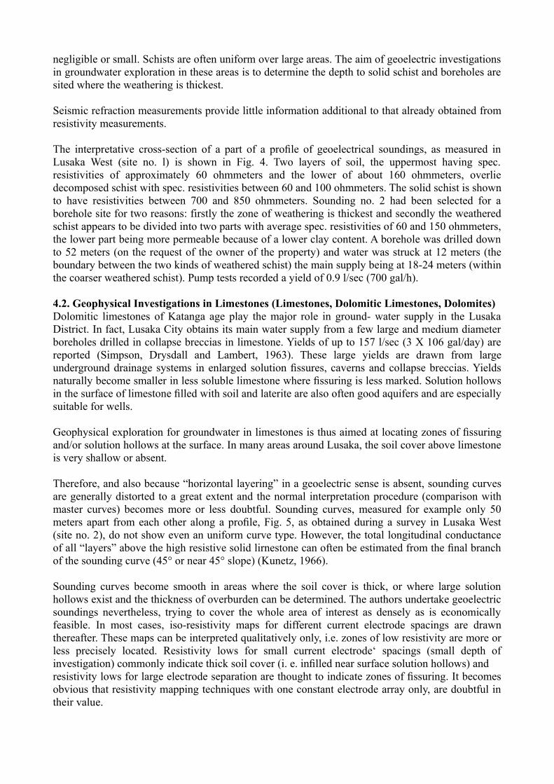
Supplementary seismic refraction measurements are useful for a detailed investigation of near-surface solution hollows and vertical bands of fractured limestone. Continuous profiling techniques, as described in Chapter 3.2, are applied. The size of solution hollows is more or less precisely evaluated by close points of depth-to-bedrock determinations, whereas fracture zones are indicated by zones of low compressional velocity in the limestone.
The upper part of Fig. 8 shows an apparent resistivity profile obtained in a limestone area with little or no soil cover. A low resistivity anomaly is shown up in the centre of the profile. To clarify whether this is due to thickening of soil cover or due to a fractured zone in otherwise more solidlimestone, a refraction profile was run also. The zone of low bedrock velocity, lower part of Fig. 8, corresponds well with the resistivity low. Thus a fractured zone in otherwise solid limestone appears
most likely.
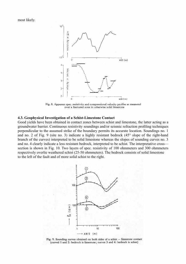
4.3. Geophysical Investigation of a Schist-Limestone ContactGood yields have been obtained in contact zones between schist and limestone, the latter acting as a groundwater barrier. Continuous resistivity soundings and/or seismic refraction profiling techniques perpendicular to the assumed strike of the boundary permits its accurate location. Soundings no. 1 and no. 2 of Fig. 9 (site no. 3) indicate a highly resistant bedrock (45° slope of the right-hand branch of the curves) interpreted to be solid limestone whereas the slopes of sounding curves no. 3 and no. 4 clearly indicate a less resistant bedrock, interpreted to be schist. The interpretative cross—section is shown in Fig. 10. Two layers of spec. resistivity of 100 ohmmeters and 300 ohmmeters respectively overlie weathered schist (25-50 ohmmeters). The bedrock consists of solid limestoneto the left of the fault and of more solid schist to the right.

A borehole drilled in the vicinity of the contact zone passed through weathered schist and encountered limestone at a depth of 18 meters. Water was struck at 18 meters, maximum supply being at 23 meters. The borehole yields 3.3 l/sec (2700 gal/h).
4.4. Geophysical Investigation of an Intrusive, Embedded in SchistIgneous rocks, in the form of intrusives into rocks of the Katanga or Basement System are not as common in Zambia as they are in other parts of Southern Africa, and thus play a minor role in groundwater supply. They act as groundwater barriers; thus good yields can be expected at theboundary between the intrusive body and adjacent country-rock.
Resistivity methods are well suited to locate intrusives as the resistivity contrast between intrusives and adjacent country rocks is usually high. (In many cases, igneous rocks have higher magnetic susceptibilities than the sediments which the have intruded, so that geomagnetic measurements might be superior.)
A small, dome-shaped intrusive body, believed to be of basic or intermediate composition, emplaced in schist has been encountered during a survey in Lusaka West (site no. 4). The interpretative cross-section is shown in Fig. 11. The dome-shaped mass underlying the plot shows high spec. resistivities in the centre, indicating fresh rock, with a decrease of spec. resistivities towards the margins being caused by an increase in permeability, following shearing and metamorphism.
A borehole was drilled between soundings no. 6 and no. 7, at the margin of the intrusive body.

Water was struck between 15, 26 and 34 meters of depth, the yielding being 4 1/sec (3200 gal/h).
4.5. Geophysical Investigations in QuartzitesQuartzites are poor aquifers and difficult to drill. In many cases only a well, dug down to solid quartzite, can be recommended. Water can be drawn from decomposed material on top of the solid quartzite.
The type of geoelectric sounding curves obtained in areas underlain by quartzites varies considerable, even at locations close to each other, a phenomenon believed to be due to large near-surface quartzite boulders. Geophysical investigations appear to be only of value to determinethe thickness of decomposed rocks above the solid quartzite so that wells can be recommended where weathering is most intense. As most quartzites form hills, boreholes, if recommended at all, should be sited at their margins or ir1 the adjacent valleys, where seasonal recharge will occur.
Resistivity and seismic refraction measurements were done during a survey in Lusaka North (site no. 5). One sounding curve and one travel-time curve obtained during that survey, are shown in Fig. 12 together with the interpretative cross-sections. The bedrock, believed to be partly fissured or decomposed (because of the relatively low compressional velocity of 3200 rn/sec) is only shown up in the seismic cross-section. The layer with a velocity of 1300 m/sec consists of quartzite boulders and decomposed rock and it was hoped that groundwater might be drawn from it. However, a borehole drilled down to 35 meters remained dry.
5. ConclusionsDifferent rock types in the Lusaka District allow for different geophysical exploration and interpretation techniques. Also, borehole yields differ over a wide range, from very poor in quartzites to excellent in dolomitic limestones.
Geoelectric soundings, using the Schlumberger array, are always undertaken, even in areas where a quantitative interpretation becomes meaningless. In general, quantitative interpretation is possible in areas underlain by schists, or where the soil cover is relatively thick, so that soundings are lessaffected by near-surface inhomogenities.
Only qualitative interpretation is possible in most areas underlain by limestones and quartzite. Generally, fractured or fissured rock is shown up as resistivity lows in a iso-resistivity map and

good yields are obtained if boreholes are drilled in these resistivity lows.
Supplementary seismic refraction methods are recommended only for detailed studies of solution hollows and bands of fractured rock in limestone.
So far, a success of 90% has been achieved, applying geophysical investigation methods for the exploration of groundwater in the Lusaka District. This compares favourably with a success rate of about 40%-50% if wild-cat drillings are done in the same area.
References
Barthelmes, A..: Application of Continuous Profiling to Refraction Shooting. Geophysics XI, 1, 24, 1946
Ebert, A.: Grundlagen zur Auswertung geoelektrischer Tiefenmessungen. Z. Angew. Geophys. 10, 1, 1943
Frost, R.: The Diurnal Variation of the Meteorological Elements of Lusaka. Dep. of Meteorology, Lusaka. Meteorol. Notes, Series A 10, 1971
Hagedoorn, .G.: The Plus-Minus Method of Interpreting Seismic Refraction Sections. Geophys. Prospecting 7, 158, 1959
Hawkins, L.V.: The Reciprocal Method of Routine Shallow Seismic Refraction Investigations. Geophysics XXVII, 806, 1961
Koefoed, 0.: An Analysis of Equivalence in Resistivity Sounding. Geophys. Prospecting XVII, 3, 327, 1969
Kunetz, G.: Geoexploration Monographs. Serie 1, Nr. 1. Berlin: Gebriider Borntrager 1966Kunetz, G., Rocroi, J. P.: Traitement Automatique des Sondages Electriques. Geophys. Prospecting
XVIII, 2, 157, 1970Maillet, R.: The Fundamental Equations of Electrical Prospecting. Geophysics XII, 4, 529, 1947Musgrave, A.W.: Seismic Refraction Prospecting. S.E.G., Tulsa, 1963Orellana, E., Mooney, H.M.: Master Tables and Curves for Vertical Electrical Sounding over
Layered Structures. Madrid: Intersciencia 1966Paterson, N.R.: Portable Fascimile Seismograph, the equipmeot and its application. Mining in
Canada, 1968Simpson, .G., Drysdall, A.R., Lambert, The Geology and Groundwater Resources of the Lusaka
Area. Geol. Surv. of Zambia, Rep. Nr. 16, 1963Smith, A. G.: The Geology of the Country around Mazabuka and Kafue. Geol. Survey of Zambia,
Rep. Nr. 2, 1964Topfer, K.D.: On the Determination of the Specific Resistivity of Pure Unconsolidated Sands. Z.
Geophys. 38, 773, 1972
Dr. phil. K.D. Topfer C.A. Legg, MSc., ARCS.University of Zambia Geological Survey DepartmentSchool of Natural Sciences P. O. Box RW 135P. O. Box 2379 Lusaka, Republic of ZambiaLusaka, Republic of Zambia