surface geophysical investigations - bureau of … · 2015-10-05 · surface geophysical...
TRANSCRIPT
Chapter 13
SURFACE GEOPHYSICALINVESTIGATIONS
Introduction
Surface geophysical surveys have been applied to mineraland petroleum exploration for many years. A magneticcompass was used in Sweden in the mid-1600s to find ironore deposits. The lateral extent of the Comstock ore bodywas mapped using self-potential methods in the 1880s. Avery crude type of seismic survey measured the energyresulting from blasting operations in Ireland in the late1800s. The idea that energy travels through a materialwith a certain velocity came from this survey. DuringWorld War I, geophysical techniques were used to locateartillery pieces. Anti-submarine warfare in World War IIled to magnetic and sonar surveys.
The main emphasis of geophysical surveys in theformative years was petroleum exploration. Technologydeveloped for oil and gas surveys led to the use of geo-physical surveys in many important facets of geotechnicalinvestigations. Geophysical surveys have been applied tocivil engineering investigations since the late 1920s, whenseismic and electrical resistivity surveys were used fordam siting studies. A seismic survey was performed inthe 1950s in St. Peter’s Basilica to locate buriedcatacombs prior to a renovation project. From the late1950s until the present time, geophysical techniques havehad an increasing role in both groundwater explorationand in geotechnical investigations. Geophysical surveysare now used routinely as part of geological investigationsand to provide information on site parameters (i.e., inplace dynamic properties, cathodic protection, depth tobedrock) that in some instances are not obtainable byother methods. Values derived from seismic geophysicalsurveys are obtained at strain levels different from somesite parameters obtained by other means.
FIELD MANUAL
2
All geophysical techniques are based on the detection ofcontrasts in different physical properties of materials. Ifcontrasts do not exist, geophysical methods will not work.Reflection and refraction seismic methods contrast com-pressional or shear wave velocities of different materials.Electrical methods depend on the contrasts in electricalresistivities. Contrasts in the densities of differentmaterials permit gravity surveys to be used in certaintypes of investigations. Contrasts in magnetic suscepti-bilities of materials permit magnetic surveying to be usedin some investigations. Contrasts in the magnitude of thenaturally existing electric current within the earth can bedetected by self-potential (SP) surveys.
Seismic refraction surveys are used to map the depth tobedrock and to provide information on the compressionaland shear wave velocities of the various units overlyingbedrock. Velocity information also can be used to calcu-late in place small-strain dynamic properties of theseunits. Electrical resistivity surveys are used to provideinformation on the depth to bedrock and information onthe electrical properties of bedrock and the overlyingunits. Resistivity surveys have proven very useful indelineating areas of contamination within soils and rockand also in aquifer delineation. Gravity and magneticsurveys are not used to the extent of seismic andresistivity surveys in geotechnical investigations, butthese surveys have been used to locate buried utilities.Self-potential surveys have been used to map leakagefrom dams and reservoirs.
Geophysical surveys provide indirect information. Theobjective of these surveys is to determine characteristicsof subsurface materials without seeing them directly.Each type of geophysical survey has capabilities andlimitations and these must be understood and consideredwhen designing a geophysical investigations program.
SURFACE GEOPHYSICAL INVESTIGATIONS
3
Geophysical interpretations should be correlatedwith real “ground-truth”data such as drill hole logs.It is very important that the results of geophysicalsurveys be integrated with the results of othergeologic investigations so that accurate interpre-tation of the geophysical surveys can be made.
The following sections provide the theory behind andguidelines for uses of geophysical surveys, particularly ingeotechnical investigations. Although this chapter doesnot provide all the detail necessary, the theory and inter-pretation methods involved in geophysical surveying areincluded in references in the bibliography. The referencesshould be used to supplement the materials presented inthis chapter.
Seismic Surveys
Seismic Refraction Surveys
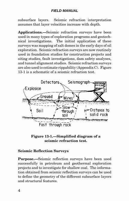
Purpose.—Seismic refraction surveys are used to deter-mine the compressional wave velocities of materials fromthe ground surface to a specified depth within the earth.For most geotechnical investigations, the maximum depthof interest will be specified by the nature of the project.In many cases the objective of a seismic refraction surveyis to determine the configuration of the bedrock surfaceand the compressional wave velocities of the underlyingmaterials. Bedrock may be defined by compressionalwave velocities. The information obtained from a seismicrefraction survey is used to compute the depths to varioussubsurface layers and the configurations of these layers.The thickness of the layers and the velocity contrastsbetween the layers govern the effectiveness and the accu-racy of the survey. Seismic refraction surveys do notprovide all compressional wave velocities or delineate all
FIELD MANUAL
4
Figure 13-1.—Simplified diagram of a seismic refraction test.
subsurface layers. Seismic refraction interpretationassumes that layer velocities increase with depth.
Applications.—Seismic refraction surveys have beenused in many types of exploration programs and geotech-nical investigations. The initial application of thesesurveys was mapping of salt domes in the early days of oilexploration. Seismic refraction surveys are now routinelyused in foundation studies for construction projects andsiting studies, fault investigations, dam safety analyses,and tunnel alignment studies. Seismic refraction surveysare also used to estimate rippability (Appendix C). Figure13-1 is a schematic of a seismic refraction test.
Seismic Reflection Surveys
Purpose.—Seismic reflection surveys have been usedsuccessfully in petroleum and geothermal explorationprojects and to investigate for shallow coal. The informa-tion obtained from seismic reflection surveys can be usedto define the geometry of the different subsurface layersand structural features.
SURFACE GEOPHYSICAL INVESTIGATIONS
5
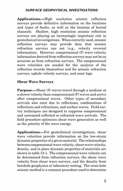
Applications.—High resolution seismic reflectionsurveys provide definitive information on the locationsand types of faults, as well as the location of buriedchannels. Shallow, high resolution seismic reflectionsurveys are playing an increasingly important role ingeotechnical investigations. When correctly used, seismicreflection surveys may provide data that seismicrefraction surveys can not (e.g., velocity reversalinformation). However, compressional (P) wave velocityinformation derived from reflection surveys may not be asaccurate as from refraction surveys. The compressionalwave velocities are needed for the analysis of thereflection records themselves and for seismic refractionsurveys, uphole velocity surveys, and sonic logs.
Shear Wave Surveys
Purpose.—Shear (S) waves travel through a medium ata slower velocity than compressional (P) waves and arriveafter compressional waves. Other types of secondaryarrivals also exist due to reflections, combinations ofreflections and refractions, and surface waves. Field sur-vey techniques are designed to suppress compressionaland unwanted reflected or refracted wave arrivals. Thefield procedure optimizes shear wave generation as wellas the polarity of the wave energy.
Applications.—For geotechnical investigations, shearwave velocities provide information on the low-straindynamic properties of a given material. The relationshipsbetween compressional wave velocity, shear wave velocity,density, and in place dynamic properties of materials areshown in table 13-1. The compressional wave velocity canbe determined from refraction surveys, the shear wavevelocity from shear wave surveys, and the density fromborehole geophysics or laboratory testing. The cross-holeseismic method is a common procedure used to determine
FIELD MANUAL
6
Table 13-1.—Determining moduli and ratios for typicalvelocities of earth materials from refraction surveys
Vp = Compressional wave velocity (ft/s) (m/s)Vs = Shear wave velocity (ft/s) (m/s)E = Young's Modulus (lb/in2) (MPa)G = Shear Modulus (lb/in2) (MPa)K = Bulk Modulus (lb/in2) (MPa)µ = Poisson's Ratio� = Density (in situ) (lb/ft3) (kg/m3)
Shear Modulus: G = �Vs2
Young's Modulus: E = 2G(1+�) Bulk Modulus: K = �(Vp-4/3Vs
2)Velocity Ratio: Vp/Vs
Poisson's Ratio: µ = (.05) [Vp/Vs]2-2/[Vp/Vs]
2-1\
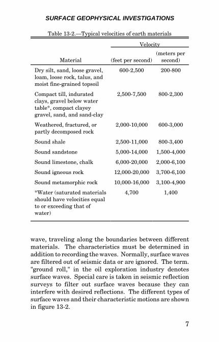
material dynamic properties. Compressional waves andshear waves are generated in one drill hole, and theseismic wave arrivals are received in companion drillhole(s). The seismic source(s) and receiver(s) are locatedat equal depths (elevations) for each recording. Drill holedeviation surveys are performed in each drill hole toaccurately determine the distances between each of thedrill holes at all recording intervals. For typical seismicvelocities of earth materials, see table 13-2.
Surface Wave Surveys
Purpose.—Surface wave surveys produce and recordsurface waves and their characteristics. Surface waveshave lower frequencies and higher amplitudes than otherseismic waves. Surface waves result from the construc-tive and destructive interference of refracted and reflectedseismic waves. Surface waves that travel along theboundaries of a body are called Stanley waves. Surfacewaves are the slowest type of seismic
SURFACE GEOPHYSICAL INVESTIGATIONS
7
Table 13-2.—Typical velocities of earth materials
Material
Velocity
(feet per second)(meters per
second)
Dry silt, sand, loose gravel,loam, loose rock, talus, andmoist fine-grained topsoil
600-2,500 200-800
Compact till, induratedclays, gravel below watertable*, compact clayeygravel, sand, and sand-clay
2,500-7,500 800-2,300
Weathered, fractured, orpartly decomposed rock
2,000-10,000 600-3,000
Sound shale 2,500-11,000 800-3,400
Sound sandstone 5,000-14,000 1,500-4,000
Sound limestone, chalk 6,000-20,000 2,000-6,100
Sound igneous rock 12,000-20,000 3,700-6,100
Sound metamorphic rock 10,000-16,000 3,100-4,900
*Water (saturated materialsshould have velocities equalto or exceeding that ofwater)
4,700 1,400
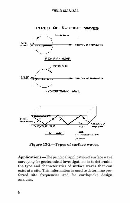
wave, traveling along the boundaries between differentmaterials. The characteristics must be determined inaddition to recording the waves. Normally, surface wavesare filtered out of seismic data or are ignored. The term."ground roll," in the oil exploration industry denotessurface waves. Special care is taken in seismic reflectionsurveys to filter out surface waves because they caninterfere with desired reflections. The different types ofsurface waves and their characteristic motions are shownin figure 13-2.
FIELD MANUAL
8
Figure 13-2.—Types of surface waves.
Applications.—The principal application of surface wavesurveying for geotechnical investigations is to determinethe type and characteristics of surface waves that canexist at a site. This information is used to determine pre-ferred site frequencies and for earthquake designanalysis.
SURFACE GEOPHYSICAL INVESTIGATIONS
9
Vibration Surveys
Purpose.—Vibration surveys measure the vibrationlevels produced by mechanical or explosive sources. Oncethese levels are determined, structures can be designed toreduce the possibility of vibration damage.
Applications.—Vibration surveys have been performedfor quarrying and mining operations, excavations,measuring the effects of traffic on sensitive equipment,and measuring the effects of aircraft (sonic vibrations) onurban areas and historical buildings. Many manufactur-ing and research facilities contain extremely sensitiveequipment with very small vibration tolerances. Vibra-tion surveys can be very useful in determining the exactlevels of allowable vibration and in designing proceduresto reduce vibration levels produced by construction andblasting activities. The same type of vibration survey canbe used in quarrying and/or mining operations to reducevibration levels while maintaining rock breakage andfragmentation.
Electrical Resistivity Surveys
The electrical resistivity of any material depends largelyon its porosity and the salinity of the water in the porespaces. Although the electrical resistivity of a materialmay not be diagnostic, certain materials have specificranges of electrical resistivity. In all electrical resistivitysurveying techniques, a known electrical current is passedthrough the ground between two (or more) electrodes. Thepotential (voltage) of the electrical field resulting from theapplication of the current is measured between two (ormore) additional electrodes at various locations. Since thecurrent is known, and the potential can be measured, anapparent resistivity can be calculated. The separation
FIELD MANUAL
10
between the current electrodes depends on the type ofsurveying being performed and the required investigationdepth.
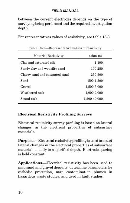
For representatives values of resistivity, see table 13-3.
Table 13-3.—Representative values of resistivity
Material Resistivity (ohm-m)
Clay and saturated silt 1-100
Sandy clay and wet silty sand 100-250
Clayey sand and saturated sand 250-500
Sand 500-1,500
Gravel 1,500-5,000
Weathered rock 1,000-2,000
Sound rock 1,500-40,000
Electrical Resistivity Profiling Surveys
Electrical resistivity survey profiling is based on lateralchanges in the electrical properties of subsurfacematerials.
Purpose.—Electrical resistivity profiling is used to detectlateral changes in the electrical properties of subsurfacematerial, usually to a specified depth. Electrode spacingis held constant.
Applications.—Electrical resistivity has been used tomap sand and gravel deposits, determine parameters forcathodic protection, map contamination plumes inhazardous waste studies, and used in fault studies.
SURFACE GEOPHYSICAL INVESTIGATIONS
11
Electrical Resistivity Sounding Surveys
Electrical resistivity sounding surveys measure verticalchanges in the electrical properties of subsurfacematerials. The electrode spacing used for resistivitysounding is variable, with the center point of the electrodearray remaining constant. The depth of investigationincreases as the electrode spacing increases.
Purpose.—Resistivity soundings are used to investigatevariations of resistivity with depth. Electrode spacing isvaried.
Applications.—Electrical resistivity soundings are com-monly used for aquifer and aquaclude delineation ingroundwater investigations. The technique has been usedfor bedrock delineation studies where there is not a suf-ficient velocity contrast to permit seismic surveying.Vertical electrical soundings have been used for largescale mineral investigations, geothermal investigations,cathodic protection and toxic waste studies, and inconjunction with self-potential surveys for seepageinvestigations.
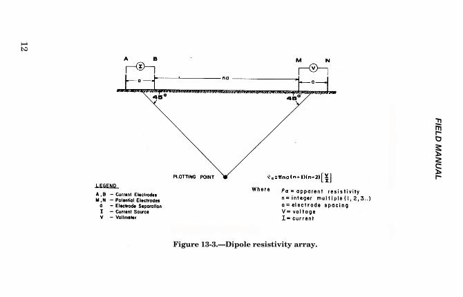
Electrical Resistivity Dipole-Dipole Surveys
Dipole-dipole surveying potential electrodes may have anyposition with respect to the pair of current electrodes.When the current and potential electrodes are positionedalong the same line, the array is referred to as an axialdipole array (figure 13-3). The current electrodes areseparated from the potential electrodes by an interval, n,which is some multiple of the current and potential elec-trodes separation, a. The separation of the current andpotential electrodes is normally equal.
FIE
LD
MA
NU
AL
12
Figure 13-3.—Dipole resistivity array.
SURFACE GEOPHYSICAL INVESTIGATIONS
13
Purpose.—Dipole-dipole arrays are used to determineboth the lateral and vertical changes in electricalproperties of subsurface materials with one electrodearray.
Applications.—The dipole-dipole array has limitedapplications in engineering and groundwater geophysics.This type of electrode array has been used primarily inmineral and geothermal exploration. The method hasbeen used to delineate abandoned mines, mappingsaltwater/fresh water interfaces, and mapping buriedstream channels.
Electromagnetic Conductivity Surveys
Electromagnetic Conductivity Profiling Surveys
Electromagnetic (EM) surveying uses time-varying, lowfrequency, electromagnetic fields induced into the earth.A transmitter, receiver, and a buried conductor arecoupled by electrical circuitry through electromagneticinduction. The characteristics of electromagnetic wavepropagation and attenuation by a material can permitinterpretation of the electrical conductivities of thesubsurface materials.
Purpose.—Since electrical conductivity is the reciprocalof electrical resistivity, electromagnetic surveys are usedto provide resistivity information on subsurface materials.Electromagnetic conductivity profiling surveys are spe-cifically used to determine lateral changes in conductivityof the subsurface materials.
Applications.—Electromagnetic surveys have been usedprimarily for mineral exploration; and with the exceptionof magnetic surveys, EM surveys are the most commonly
FIELD MANUAL
14
used geophysical surveys for minerals. EM surveys havebeen used in engineering and groundwater investigations.The method is found to be particularly useful in mappingcontaminant plumes and buried metallic waste such asmetal drums containing hazardous chemicals. EM sur-veys are suited to hazardous waste studies because thesurveying procedure does not require equipment to touchpotentially contaminated ground. The method has beenused to locate buried pipes and cables and to locatelandmines.
Electromagnetic Conductivity Sounding Surveys
Purpose.—Electromagnetic conductivity sounding sur-veys are used to determine vertical changes in con-ductivity of subsurface material.
Applications.—Electromagnetic sounding surveys canlocate areas of permafrost, gravel deposits, map bedrocktopography, and provide general geological information.EM sounding and profiling surveys have been applied tomapping areas of salt water intrusion, archaeologicalinvestigations, and fault studies.
Ground Penetrating Radar Surveys
Purpose
Ground penetrating radar (GPR) surveys have the samegeneral characteristics as seismic surveys. The depth ofinvestigation with GPR is extremely shallow when com-pared to seismic surveys. This disadvantage is partiallyoffset by the much better resolution of GPR.

SURFACE GEOPHYSICAL INVESTIGATIONS
15
Applications
Ground penetrating radar surveys can be used for avariety of very shallow geotechnical investigations,including the locations of pipes or other buried manmadeobjects such as timbers, very high resolution mapping ofnear-surface geology, and detecting cavities, piping, andleakage in dams. The applications are limited by the veryshallow penetration depth of the very high radarfrequencies. Silts, clays, salts, saline water, the watertable, and any other conductive materials in the sub-surface severely restrict or stop penetration of radar.
Self-Potential Surveys
Purpose
Self-potential ([SP] spontaneous potential or naturalpotential) is the natural electrical potential existingwithin the earth due to many causes. These causes can beclassified broadly into two groups (excluding manmadecauses):
Mineralization Potential.—Mineralization potential iscommonly the result of chemical concentration cellsformed when conductive mineral deposits, such asgraphite or sulfide, are intersected by the water table.Mineralization potentials are almost always negative andmay have values up to several hundred millivolts. Back-ground potentials can be either positive or negative andusually have values of only a few tens of millivolts.
Background Potential.—Background potential iscommonly the result of (a) two electrolytes of differentconcentration being in contact with one another,(b) electrolytes flowing through a capillary system or
FIELD MANUAL
16
porous media, (c) an electrolyte in contact with a solid,and (d) electromagnetically induced telluric (large scaleflow in the earth’s crust) currents.
The background potentials developed by electrolytes flow-ing through a capillary system or porous media (calledelectro-filtration or streaming potentials) are used tostudy seepage. Water flowing through a capillary systemcollects and transports positive ions from the surroundingmaterials. The positive ions accumulate at the exit pointof the capillary, leaving a net positive charge. Theuntransported negative ions accumulate at the entrypoint of the capillary leaving a net negative charge. If thestreaming potentials developed by this process are ofsufficient magnitude to measure, the entry point and theexit point of zones of concentrated seepage may bedetermined from the negative and positive self potentialanomalies.
Applications
Self-potential surveys have been used to map the lateralextent of mineral deposits and, in some instances, provideinformation of the configuration of the deposits. Anotherexploration application has been to map the depth to andconfiguration of certain geothermal areas. Normally, ingeothermal applications, self-potential surveying is usedin conjunction with other geophysical surveys (gravity,seismic, and electrical).
In geotechnical investigations, self-potential surveys havebeen used to map leakage paths from dams. Self-potential surveying has also been used to map leaks fromcanals and buried pipelines that transport liquids.Detachment walls and lateral limits of some landslidemasses have been mapped with self-potential surveys.
SURFACE GEOPHYSICAL INVESTIGATIONS
17
Self-potential surveying may play an important role inhazardous waste investigations and in monitoring leakagefrom dams.
Magnetic Surveys
Purpose
Magnetic surveys measure anomalous conditions withinthe Earth’s magnetic field. The Earth’s magnetic fieldresembles the field of a bar magnet. The field is twice asstrong in the polar regions than at the equator. Theintensity of the field in the polar regions is approximately60,000 gammas; while at the equator, the intensity isapproximately 30,000 gammas. The Earth’s magneticfield is not symmetrical but contains many large per-turbations due to local variations in magnetic materialsand larger magnetic features. Within the Earth’s field,anomalies on the order of one gamma to several thousandgammas are detected by magnetic surveys. The smalleranomalies can be detected with complex instruments, andthe larger anomalies can be detected with simpler instru-ments and field techniques.
Applications
Magnetic surveys have their widest applications in petro-leum and mineral exploration programs. For applicationsin petroleum exploration, the application is somewhatsimpler because the sources of most magnetic anomalieslie within the basement complex and the overlyingsediments are often "transparent" to magnetic surveys.
In geotechnical investigations, magnetic surveys havebeen used to detect buried barrels of contaminated
FIELD MANUAL
18
materials and to detect and map buried pipelines.Magnetic surveys have also been used in archaeologicalinvestigations.
Gravity Surveys
Purpose
Gravity anomalies are the result of contrasts in densitiesof materials in the Earth. If all the materials within theEarth were layered horizontally and were of uniformdensity, there would be no density contrasts. Densitycontrasts of different materials are controlled by anumber of different factors; the most important are thegrain density of the particles forming the material, theporosity of the material, and the interstitial fluids withinthe material. Generally, soil and shale specific gravitiesrange from 1.7 to 2.2. Massive limestone specific gravitiesaverage 2.7. While this range of values may appear to befairly large, local contrasts will be only a fraction of thisrange. A common order of magnitude for local densitycontrasts is 0.25. Density contrasts can be determined bycalculating the gravity effect of a known model andcomparing that effect with the observed gravitydetermined from a gravity survey.
Applications
Gravity surveys provide an inexpensive determination ofregional structures that may be associated withgroundwater aquifers or petroleum traps. Gravity sur-veys have been one of the principal exploration tools inregional petroleum exploration surveys. Gravity surveyshave somewhat limited applications in geotechnicalinvestigations. Gravity surveys have been used to obtaininformation on bedrock depths and the top of rock
SURFACE GEOPHYSICAL INVESTIGATIONS
19
configuration in areas where it has not been possible orpractical to use other geophysical techniques. Micro-gravity (high-precision) surveys have been used in a fewinstances to obtain information on the success of groutingprograms. In these cases, microgravity surveys are per-formed before and after grouting operations and densitycontrasts of the two surveys are compared. Microgravitysurveys have been used for archaeological investigations.
Glossary
A
Accelerometer – Transducer with output proportional toacceleration. A moving coil geophone (type oftransducer) with a response proportional tofrequency may operate as an accelerometer.
Acoustic Logging – borehole log of any of severalaspects of acoustic-wave propagation (e.g., a sonic,amplitude, character, or three-dimensional log).
Air Wave – Energy from a shot which travels in the airat the velocity of sound.
Amplitude – The size of a signal, either in the ground orafter amplification. Usually measured from the zeroor rest position to a maximum excursion. Theamplitude of a signal has units based on themeasurement of the signal (e.g., acceleration (inchper square second [in/sec2]), velocity (inches persecond [in/sec]) or displacement (inches [in]).
Analog – (1) A continuous physical variable (such as volt-age or rotation) that has a direct relationship toanother variable (such as acceleration) with one
FIELD MANUAL
20
proportional to the other. (2) Continuous as opposedto discrete or digital.
Anomaly – A deviation from normal or the expected. Forexample, a travel time anomaly, Bouger anomaly,free-air anomaly.
Apparent Velocity – (1) The velocity that a wave-frontregisters on a line of geophones. (2) The inverseslope of a time-distance curve.
Automatic Gain Control (AGC) – The outputamplitude controls the gain of a seismic amplifier,usually individual for each channel; but sometimes,multi-channel devices are used.
B
Basement (Complex) – (1) generally of igneous andmetamorphic rocks overlain unconformably bysedimentary strata. (2) Crustal layer beneath asedimentary layer and above the Mohorovicicdiscontinuity.
Bedrock – Any solid rock exposed at the surface of theearth or overlain by unconsolidated material.
Bit – A binary digit; either a 1 (one) or 0 (zero).
Body Waves – The only waves that travel through theinterior of a body consisting of P-waves and S-waves.
Byte – Word.
C
Cable – The assembly of electrical conductors used toconnect geophone groups or other instruments.
SURFACE GEOPHYSICAL INVESTIGATIONS
21
Casing – Tubing or pipe used to line drill holes or shot-holes to keep them from caving.
Cathodic Protection – Electrical corrosion protectionfor pile foundations, electrical grounding mats, bur-ied pipelines, or any metal subject to corrosion.
Channel – (1) A single series of interconnected devicesthrough which geophysical data can flow from sourceto recorder. (2) An elongated depression or geologicalfeature. (3) An allocated portion of the radio fre-quency spectrum.
Channel Wave – An elastic wave propagated in a layerof lower velocity than layers on either side. Energyis largely prevented from escaping from the channelbecause of repeated total reflection at the channelboundaries or because rays that tend to escape arerefracted back toward the channel.
Character. – (1) The recognizable aspect of a seismicevent, usually displayed in the waveform thatdistinguishes the event from other events. Usually,a frequency or phasing effect, often not definedprecisely and dependent upon subjective judgment.
Common Depth Point (CDP). – The same portion ofsubsurface that produces reflections at differentoffset distances on several profiles.
Compressional Wave – An elastic body wave withparticle motion in the direction of propagation.Same as P-waves, longitudinal wave, dilatationwave, irrotational.
Converted Wave – A wave that is converted fromlongitudinal to transverse, or vice versa, uponreflection or refraction at oblique incidence from aninterface.
FIELD MANUAL
22
Critical Angle – Angle of incidence, �c, for which therefracted ray grazes the contact between two media(of velocities V1 and V2):
sin �c = V1/V2
Critical Distance – (1) The offset at which a refractedevent becomes the first break; cross-over distance.(2) The offset at which the reflection time equals therefraction time (i.e., the offset at which the reflectionoccurs at the critical angle).
Crossfeed (Crosstalk) – Interference resulting from theunintentional pickup of information or noise fromanother channel.
D
Datum – (1) The arbitrary reference level to which meas-urements are corrected. (2) The surface from whichseismic reflection times or depths are measured,corrections having been made for local topographicand/or weathering variations. (3) The reference levelfor elevation measurements, often sea level.
Delay Time – (l) In refraction work, the additional timetaken for a wave to follow a trajectory to and along aburied marker over that which would have beentaken to follow the same marker hypothetically atthe ground surface or at a reference level. Normally,delay time exists separately under a source andunder a detector and depends on the depth of themarker at wave incidence and emergence points.Shot delay time plus geophone delay time equalsintercept time. (2) Delay produced by a filter.(3) Time lag introduced by a delay cap.
SURFACE GEOPHYSICAL INVESTIGATIONS
23
Diffraction – (1) Scattered energy which emanates froman abrupt irregularity, particularly common wherefaults cut reflecting interfaces. The diffracted energyshows greater curvature than a reflection (except incertain cases where there are buried foci), althoughnot necessarily as much as the curve of maximumconvexity. Diffraction frequently blends with areflection and obscures the fault location or becomesconfused with dip. (2) Interference produced byscattering at edges. (3) Causes energy to be trans-mitted laterally along a wave crest. When a portionof a wave train is interrupted by a barrier,diffraction allows waves to propagate into the regionof the barrier's geometric shadow.
Digital – Representation of quantities in discrete units.An analog system represents data as a continuoussignal.
Dipole – A pair of closely spaced current electrodes thatapproximates a dipole field from a distant pair ofvoltage detecting electrodes.
E
Elastic Constants –
(1) Bulk modulus, k. – The stress-strain ratio underhydrostatic pressure.
kP
V V= ∆
∆ /
where �P = pressure change, V = volume, and �V =volume change.
FIELD MANUAL
24
(2) Shear modulus, �. – rigidity modulus, Lame'sconstant. The stress-strain ratio for simple shear.
µ = F A
L L
t /
/∆
where Ft = tangential force, A = cross-sectional area,L = distance between shear planes, and �L = sheardisplacement. Shear modulus can also be expressedin terms of other moduli as:
µσ
=+E
( )1
where E = Young's modulus, and � = Poisson's ratio.
(3) Young's modulus, E. – The stress-strain ratiowhen a rod is pulled or compressed.
EF A
L L= ∆
∆/
/
where �F/A = stress (force per unit area), L =original length, and �L = change in length.
(4) Lame' constant, �. – a tube is stretched in theup-direction by a tensile stress, S, giving an upwardstrain, s, and S’ is the lateral tensile stress needed toprevent lateral contraction, then:
λ = S
s
'
This constant can also be expressed in terms ofYoung’s modulus, E, and Poisson’s ratio, �:
SURFACE GEOPHYSICAL INVESTIGATIONS
25
λ σσ σ
=+ −
E
( )( )1 1 2
Electromagnetic – Periodically varying field, such aslight, radio waves, radar.
End Line – Shotpoints that are shot near the end of thespread.
F
Fan Shooting – An early use of the refraction seis-mograph to find salt domes within a thick, low-velocity section; detectors located in widely spacedfan-like arrays radiating from the shot locations.
Filter – (1) A device that discriminates against some ofthe input information. The discrimination is usuallyon the basis of frequency, although other bases suchas wavelength or moveout (see velocity filter) may beused. The act of filtering is called convolution.(2) Filters may be characterized by their impulseresponse or, more usually, by their amplitude andphase response as a function of frequency. (3) Band-pass filters are often specified by successively listingtheir low-cutoff and high-cutoff points. (4) Notchfilters reject sharply at a particular frequency.(5) Digital filters filter data numerically in the timedomain. Digital filtering can be the exact equivalentof electrical filtering. Digital filtering is very versa-tile and permits easy filtering according toarbitrarily chosen characteristics.
First Break or First Arrival – The first recorded signalattributable to seismic wave travel from a source.First breaks on reflection records provide informa-tion about weathering. Refraction work is based
FIELD MANUAL
26
principally on the first breaks, although secondary(later) refraction arrivals are also used.
Frequency – The repeat rate of a periodic wave,measured in hertz. Angular frequency, measured inradians per second.
G
Galvanometer – A coil suspended in a constant mag-netic field. The coil rotates through an angle propor-tional to the electrical current flowing through thecoil. A small mirror on the coil reflects a light beamproportional to the galvanometer rotation.
Geophone (Seismometer, Jug) – Instrument used toconvert seismic energy (vibration) into electricalenergy.
Geophone Station – Location of a geophone on aspread.
Gravimeter. – An instrument for measuring variationsin gravitational attraction.
Gravity Survey – A survey performed to measure thegravitational field strength, or derivatives, that arerelated to the density of different rock types.
Group Velocity – The velocity at which most of theenergy in a wave train travels. In dispersive mediawhere velocity varies with frequency, the wave trainchanges shape as it progresses so that individualwave crests appear to travel at velocities (the phasevelocity) different from the overall energy asapproximately enclosed by the envelope of the wavetrain. The velocity of the envelope is the groupvelocity. Same as dispersion.
SURFACE GEOPHYSICAL INVESTIGATIONS
27
H
Head Wave – See refraction wave.
Hidden Layer – A layer that cannot be detected byrefraction methods; typically, a low velocity layerbeneath a high velocity layer.
Hydrodynamic Wave – A seismic surface wavepropagated along a free surface. The particle motionis elliptical and prograde (M2 type Rayleigh orSezawa) (e.g., Rayleigh-type wave dependent uponlayering).
Hydrophone (Pressure Detector) – A detector sensi-tive to variations in pressure, as compared to ageophone, which is sensitive to motion. Used whenthe detector can be placed below a few feet of watersuch as in marine or marsh applications or as a wellseismometer. The frequency response of the hydro-phone depends on the depth beneath the surface.
I
In-line Offset – Shot points that are in line, but offset toa spread.
L
Lead – An electrical conductor (wire cable) used toconnect electrical devices. Geophones are connectedto cables at the takeouts via leads on the geophones.
Love Wave – A surface seismic wave associated with lay-ering. This wave is characterized by horizontalmotion perpendicular to the direction of propagation,with no vertical motion.
FIELD MANUAL
28
Low-velocity Layer (LVL) – The surface layer that haslow seismic velocity.
M
Magnetic Survey – A survey to measure the magneticfield or its components as a means of locatingconcentrations of magnetic materials or determiningdepth to basement.
Mis-tie – (1) The time difference obtained on carrying areflection event or some other measured quantityaround a loop; or the difference of the values atidentical points on intersecting lines or loops. (2) Inrefraction shooting, the time difference from reversedprofiles that gives erroneous depth and dipcalculations.
Multiple – Seismic energy that has been reflected morethan once (e.g., long-path multiple, short-pathmultiple, peg-leg multiple, and ghosts).
N
Noise – (1) Any undesired signal or disturbance that doesnot represent any part of a message from a specifiedsource. (2) Sometimes restricted to random energy.(3) Seismic energy that is not resolvable as re-flections. Noise can include microseisms, shot-generated noise, tape-modulation noise, andharmonic distortions. Sometimes divided into co-herent noise (including non-reflection coherentevents) and random noise (including wind noise,instrument noise, and all other energy which is non-coherent). (3) Random noise can be attenuated bycompositing signals from independent measure-ments. (4) Sometimes restricted to seismic energy
SURFACE GEOPHYSICAL INVESTIGATIONS
29
not derived from the shot explosion. (5) Disturbancesin observed data due to more or less random inhomo-geneities in surface and near-surface material.
Noise Analysis – A profile or set of profiles used togather data for an analysis of coherent noise. Usedto design geophone arrays in reflection surveys.
Noise Survey (Ground Noise Survey) – A survey ofambient, continuous seismic noise levels within agiven frequency band. This technique is a useful toolfor detecting some geothermal reservoirs becausethey are a source of short-period seismic energy.
O
On-line – Shot points that are not at any point on aspread other than at the ends.
Original Data – (1) Any element of data generateddirectly in the field in the investigation of a site.(2) A new element of data resulting from a directmanipulation or compilation of field data.
Oscillograph – A device that records oscillations as acontinuous graph of corresponding variation in anelectric current or voltage.
Oscilloscope – A device that visually displays anelectrical wave on a screen (e.g., on a cathode raytube).
FIELD MANUAL
30
P
Phase Velocity – The velocity of any given phase (suchas a trough or a wave of single frequency); it maydiffer from group velocity because of dispersion.
Plant – The manner in which a geophone is placed or thecoupling to the ground.
Primacord – An explosive rope that can be used to eitherconnect explosive charges or to detonate separatelyas a primary energy source.
Profile – The series of measurements made from severalshotpoints to a recording spread from which aseismic data cross section or profile can beconstructed.
R
Radar – An exploration method where microwaves aretransmitted into a medium and are reflected back byobjects or layers. The reflected microwaves are re-ceived and processed to provide an image of thesubsurface. May be used for shallow penetrationsurveys.
Rayleigh Wave – A seismic wave propagated along afree surface. The particle motion is elliptical andretrograde.
Ray Path – The path of a seismic wave. A line every-where perpendicular to wave-fronts (in isotropicmedia).
Reconnaissance – (1) A general examination of a regionto determine its main features, usually preliminaryto a more detailed survey. (2) A survey to determine
SURFACE GEOPHYSICAL INVESTIGATIONS
31
regional geological structures or to determinewhether economically prospective features exist,rather than to map an individual structure.
Reflection Survey – A survey of geologic structure usingmeasurements made of arrival times of seismicwaves that have been reflected from acousticimpedance change interfaces.
Refraction Survey – A survey of geologic structureusing compressional or head waves. Head wavesinvolve energy that enters a high-velocity medium(refractor).
Refraction Wave (Headwave, Mintrop Wave,Conical Wave) – Wave travel from a point sourceobliquely downward to and along a relatively highvelocity formation or marker and then obliquelyupward. Snell's law is obeyed throughout the tra-jectory. Angles of incidence and of emergence at themarker are critical angles. Refracted waves typicallyfollowing successively deeper markers appear as firstarrivals with increasing range (shot to detectordistance). Refracted waves following differentmarkers may have different arrival times for anygiven range. Refracted waves cannot arise for anglesof incidence less than the critical angle for any givenmarker. At the critical angle, the refracted wavepath (and travel time) coincides with that of a wideangle reflection.
Refractor (Refraction Marker) – An extensive,relatively high-velocity layer underlying lower velo-city layers that transmits a refraction wave nearlyhorizontally.
FIELD MANUAL
32
Resistivity – An electrical property of rock reflecting theconductivity of an electrical current. Resistivity isthe ratio of electric field intensity to current density.
Resistivity Meter – A general term for an instrumentused to measure the in place resistivity of soil androck materials.
Resistivity Survey – A survey that measures electricfields and earth resistivity of a current induced intothe ground.
Reverse Profile – A refraction seismic profile generatedby shooting both ends of a spread.
Roll-along – A mechanical or electrical switch thatconnects different geophones (or geophone groups) tothe recording instruments. The use of a roll-alongswitch permits common depth point reflection datato be easily acquired in the field.
S
Seismic Amplifier – An electronic device used to in-crease the electrical amplitude of a seismic signal.
Seismic Camera – A recording oscillograph used tomake a seismic record.
Seismic Cap – A small explosive designed to be deto-nated by an electric current that detonates anotherexplosive. These caps are designed to provide veryaccurate time control on the shot.
Seismic Velocity – The rate of propagation of seismicwaves through a medium.
Seismogram – A seismic record.
SURFACE GEOPHYSICAL INVESTIGATIONS
33
Self-potential (Spontaneous Potential, NaturalPotential, SP) – The direct current or slowlyvarying natural ground voltage between nearby non-polarizing electrodes.
Shear Wave – A body wave with the particle motionperpendicular to the direction of propagation. (Sameas S-wave, equivoluminal, transverse wave.)
Shooter – The qualified, licensed individual (powder-man) in charge of all shot point operations andexplosives on a seismic crew.
Shot Depth – The distance from the surface down to theexplosive charge. The shot depth is measured to thecenter or bottom of the charge with small charges.The distances to both the top and bottom of thecolumn of explosives are measured with largecharges.
Shot Instant (Time Break, TB, Zero Time) – Theinstant at which a shot is detonated.
Shot Point – Location of the energy source used ingenerating a particular seismogram.
Signal Enhancement – A process used in seismographsand resistivity systems to improve the signal-to-noise ratio by real-time adding (stacking) ofsuccessive waveforms from the same source point.Random noise tends to cancel out, and the coherentsignal tends to add or stack.
Snell’s Law – When a wave crosses a boundary betweentwo isotropic mediums, the wave changes directionsuch that the sine of the angle of incidence of thewave divided by the velocity of the wave in the firstmedium equals the sine of the angle of refraction of
FIELD MANUAL
34
the wave in the second medium divided by thevelocity of the wave in the second medium (seecritical angle).
Spread – The layout of geophone groups from which datafrom a single shot are simultaneously recorded.
Stanley Wave – A type of seismic surface wave prop-agated along an interface.
Surface Wave – Energy that travels along or near thesurface (ground roll).
T
Takeout – The connections on a multiconductor cable forconnecting geophones. May refer to the short cableleads from the geophones (pigtails).
Time Break – The mark on a seismic record that indi-cates the shot instant or the time the seismic wavewas generated.
Trace – A record of one seismic channel. This channelmay contain one or more geophones.
V
Vibration Monitor – A sensitive, calibrated recorder ofground and structural acceleration and velocity.Measurements are made to determine vibrationamplitudes and modal frequencies of buildings,towers, etc., under ambient conditions, as well as todetect potentially damaging vibrations caused byblasting, pile driving, etc.
SURFACE GEOPHYSICAL INVESTIGATIONS
35
Vibroseis – A seismic energy source consisting of con-trolled frequency input into the earth by way of largetruck mounted vibrators. Trademark of ContinentalOil Company (Conoco).
W
Wave Length – The distance between successive similarpoints on two adjacent cycles of a wave measuredperpendicular to the wavefront.
Wave Train – (1) The sum of a series of propagatingwave fronts emanating from a single source. (2) Thecomplex wave form observed in a seismogramobtained from an explosive source.
Weathering Spread – A short-spaced geophone intervalrefraction spread used to provide corrections torefraction data caused by delay times in near-surface, low-velocity materials.
WWV(B) – The National Institute of Standards and Tech-nology (NIST) radio stations that broadcast time andfrequency standards.
For the definition of other geophysical terms used in thismanual, refer to: Glossary of Terms Used in GeophysicalExploration, Society of Exploration Geophysicists, Tulsa,Oklahoma, 1984.
FIELD MANUAL
36
Bibliography
Mooney, H.M., Handbook of Engineering Geophysics,Volume 1: Seismic, Bison Instruments, Inc., Minneapolis,Minnesota, 1984.
Telford, W.M., et al., Applied Geophysics, CambridgeUniversity Press, New York, New York, 1976.
U.S. Corps of Engineers, Geophysical Exploration forEngineering and Environmental Investigations,Engineering Manual EM 111-1-1802, 1995.
U.S. Geological Survey, Application of Surface Geophysicsto Ground-Water Investigations, Chapter D1, Book 2,Techniques of Water-Resources Investigations of theUnited States Geological Survey, 1974.
Van Blaricom, R., compiler, Practical Geophysics II for theExploration Geologist, Second Edition, Northwest MiningAssociation, Spokane, Washington, 1992.
Ward, S.H., editor, Geotechnical and EnvironmentalGeophysics, Society of Exploration Geophysics, Tulsa,Oklahoma, 1990.