geotechnical considerations in the context of ccs dr ... · geotechnical considerations in the...
TRANSCRIPT

1
Geotechnical Considerations in the Context of CCS
by
Dr Britta Bienen
The LRET Research CollegiumSouthampton, 11 July – 2 September 2011
Geotechnical considerations in the context of carbon storage in ocean spaces
Centre for Offshore Foundation Systems, University of Western AustraliaBritta Bienen
Themes
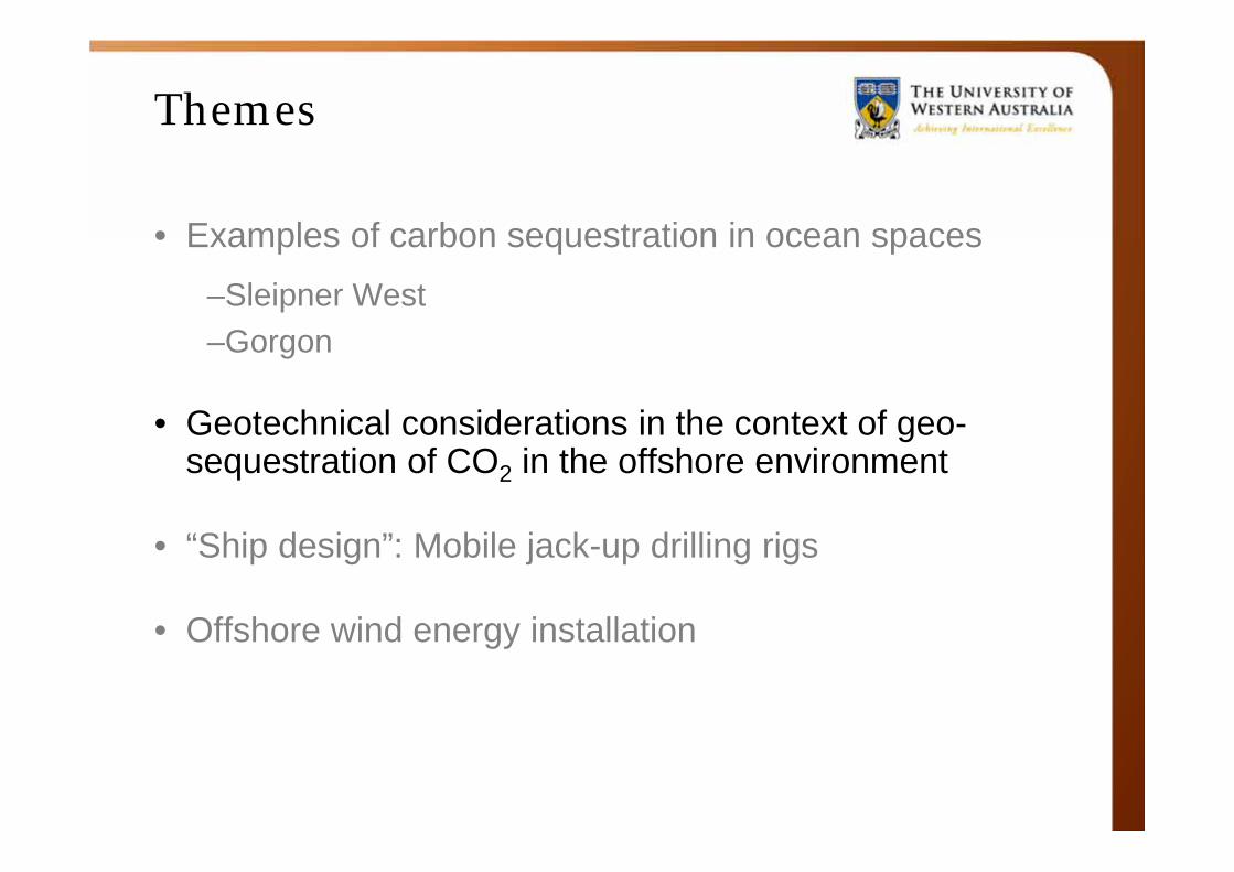
• Examples of carbon sequestration in ocean spaces
–Sleipner West–Gorgon
• Geotechnical considerations in the context of geo-sequestration of CO2 in the offshore environment
• “Ship design”: Mobile jack-up drilling rigs
• Offshore wind energy installations
Geo-sequestration
Geological storage (aka geo-sequestration)• Injection of carbon dioxide, generally in supercritical
form, directly into underground geological formations• Suggested as storage sites :
Oil fields, gas fields, saline formations, unmineable coalseams, and saline-filled basalt formations
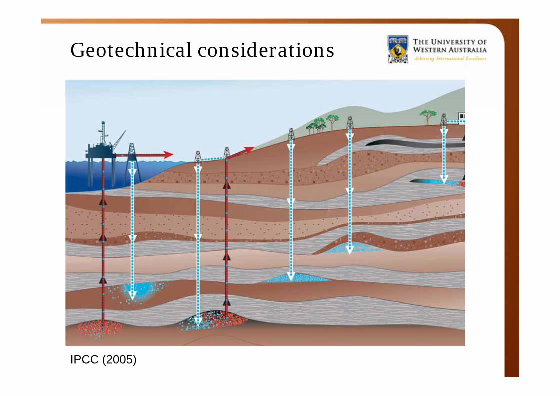
• Various trapping mechanisms prevent the CO2 from escaping to the surface
– physical (e.g., highly impermeable caprock)– geochemical
Other forms of CO2 ocean storage
• Dissolution: depths of 1000 – 3000 m, upward-plume, CO2 dissolves in seawater
• Lake deposits: depths > 3000 m, downward-plume, expected delay dissolution of CO2, possibly for millennia
• Bicarbonate(s): chemical reaction to combine CO2 with carbonate mineral (such as limestone)
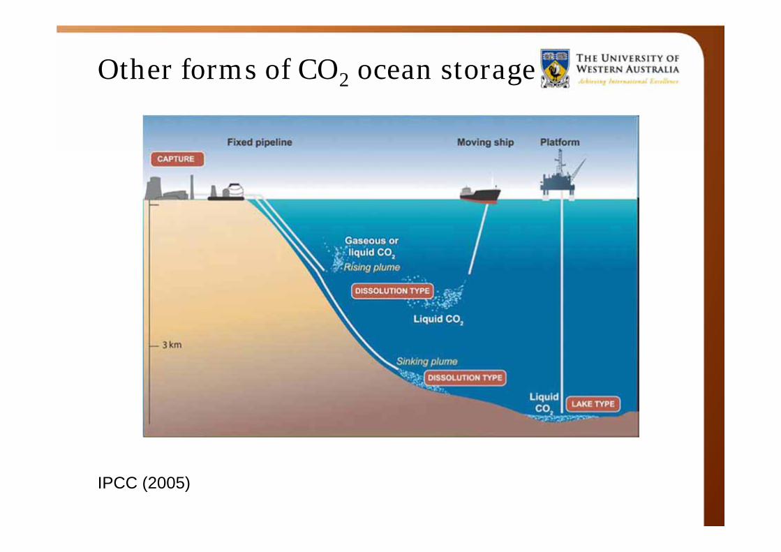
Other forms of CO2 ocean storage
IPCC (2005)
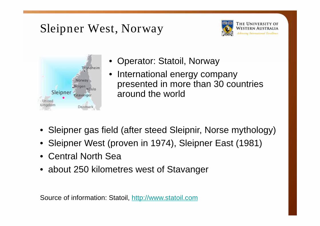
Sleipner West, Norway
• Operator: Statoil, Norway• International energy company
presented in more than 30 countries around the world
Source of information: Statoil, http://www.statoil.com
• Sleipner gas field (after steed Sleipnir, Norse mythology)• Sleipner West (proven in 1974), Sleipner East (1981)• Central North Sea• about 250 kilometres west of Stavanger
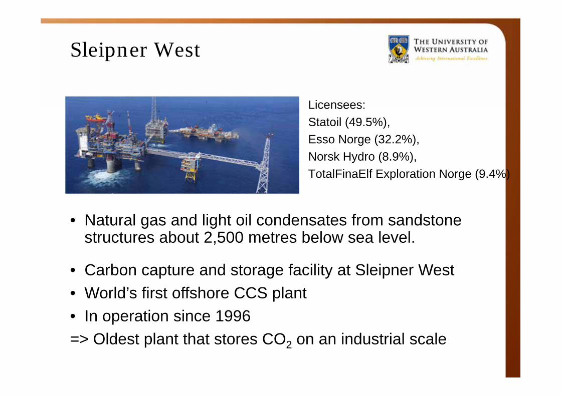
Sleipner West
Licensees:Statoil (49.5%),Esso Norge (32.2%),Norsk Hydro (8.9%),TotalFinaElf Exploration Norge (9.4%)
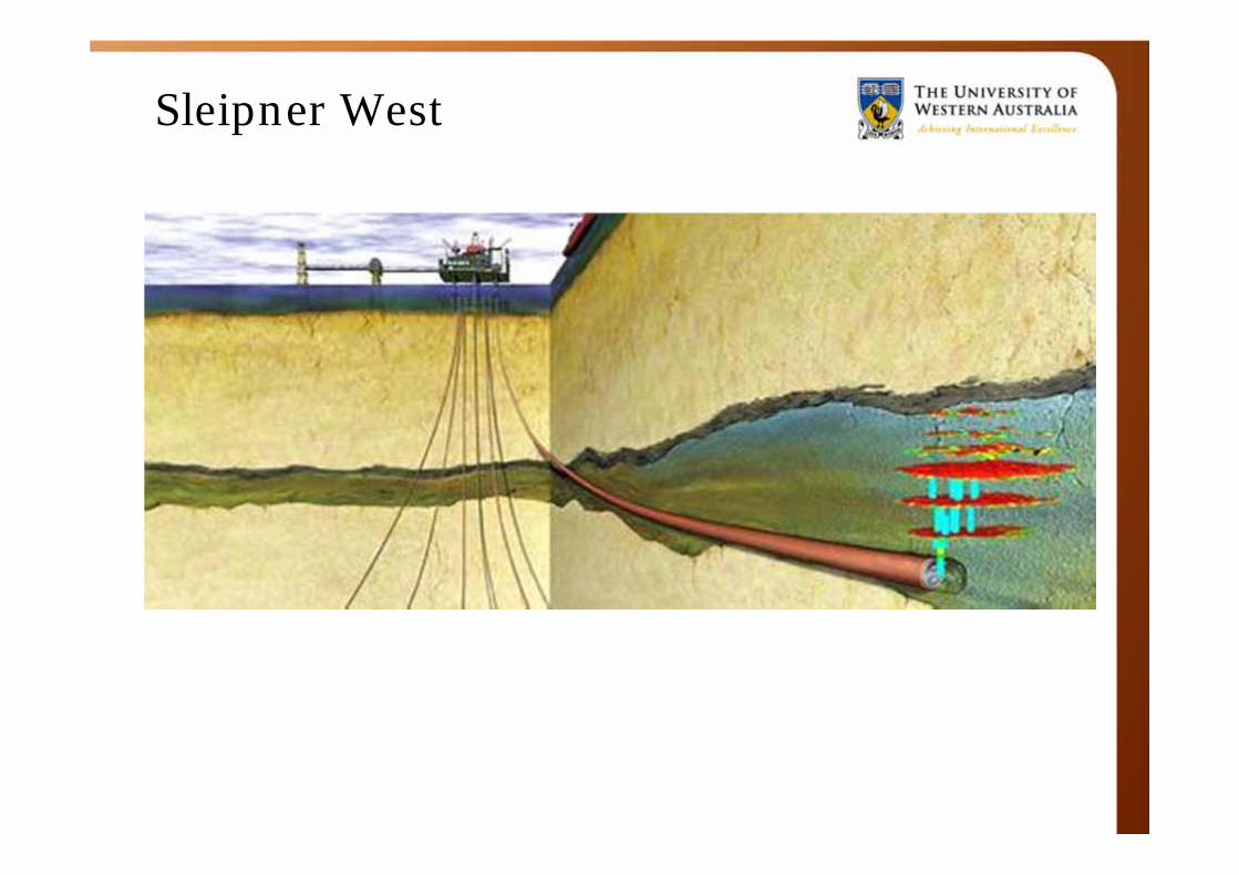
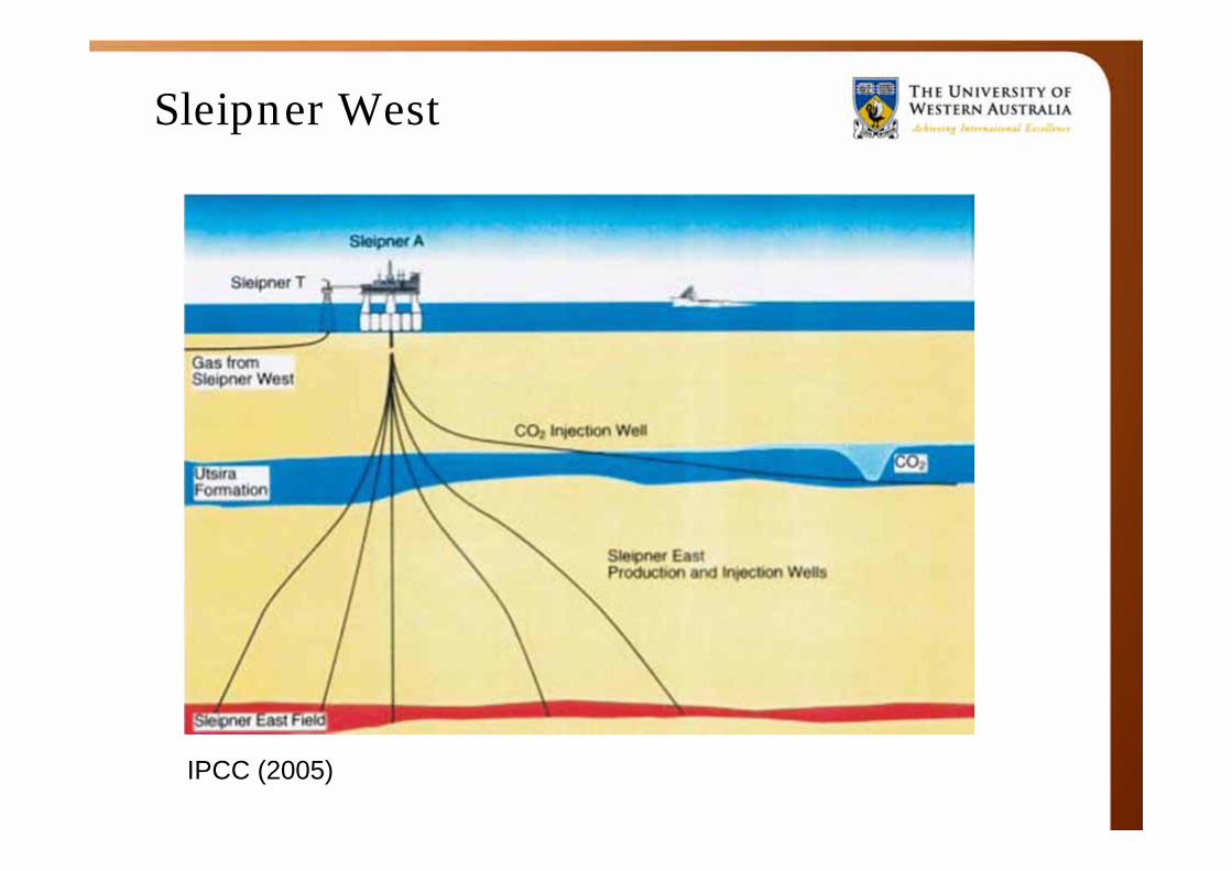
• Natural gas and light oil condensates from sandstone structures about 2,500 metres below sea level.
• Carbon capture and storage facility at Sleipner West• World’s first offshore CCS plant• In operation since 1996=> Oldest plant that stores CO2 on an industrial scale
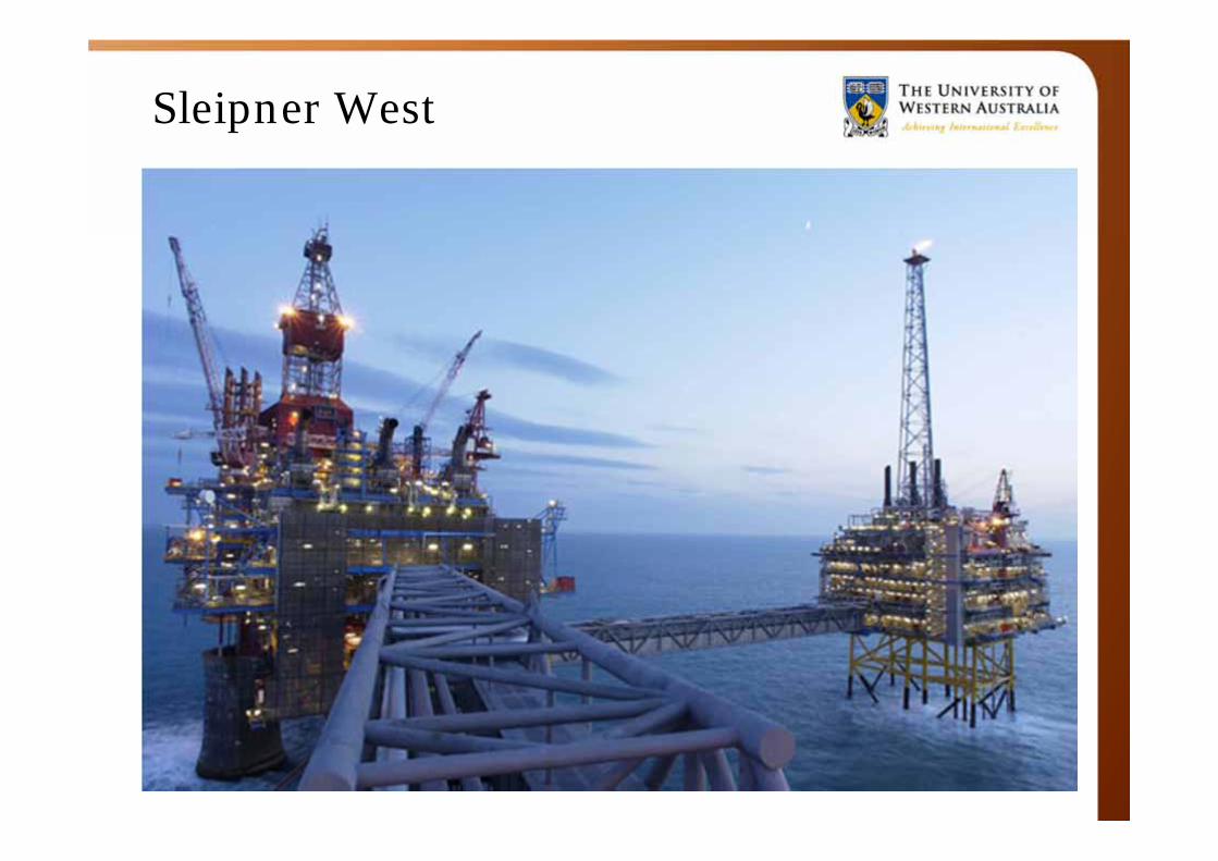
Sleipner West
Sleipner West
Sleipner West
IPCC (2005)
Sleipner West
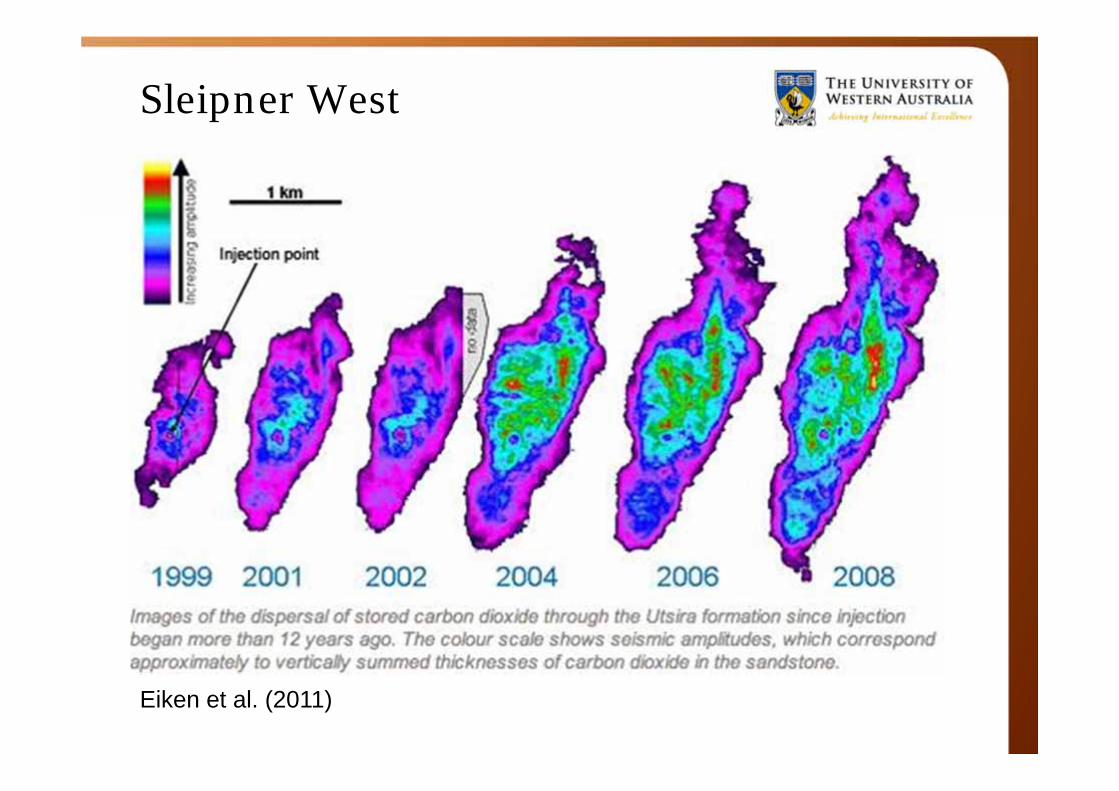
Eiken et al. (2011)
Statoil, further projects
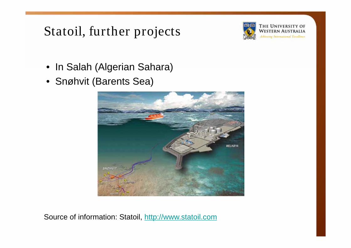
• In Salah (Algerian Sahara)• Snøhvit (Barents Sea)
Source of information: Statoil, http://www.statoil.com
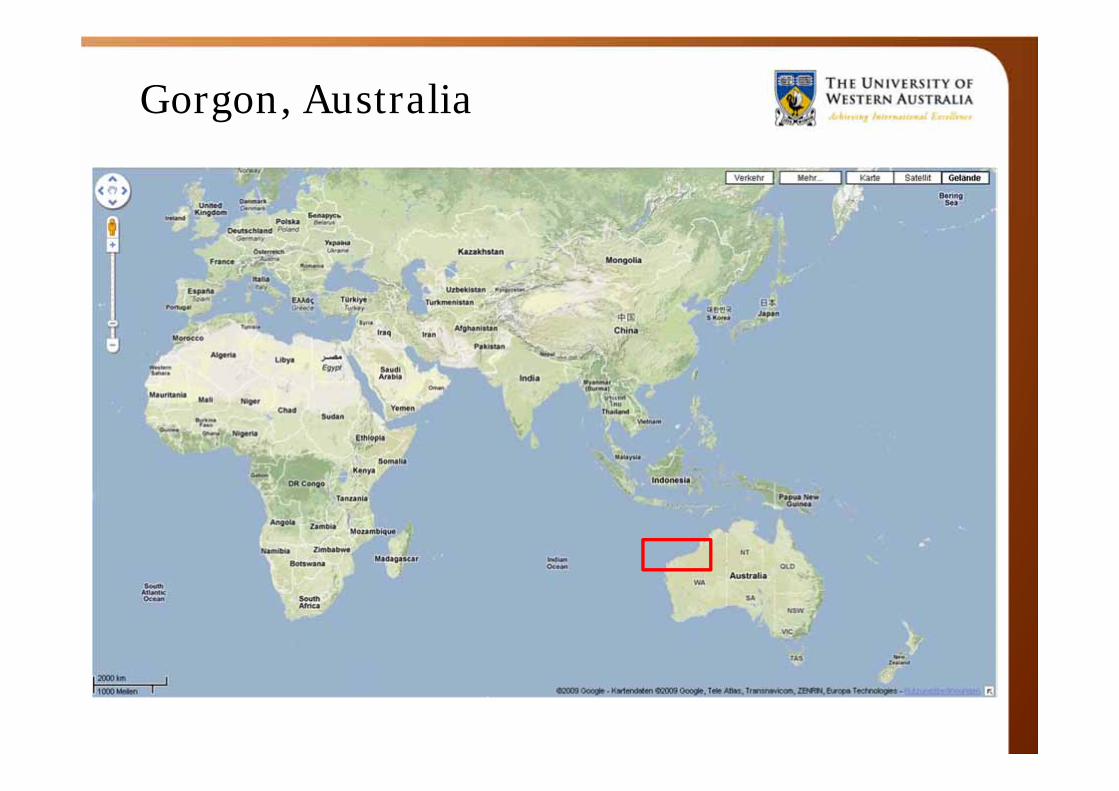
Gorgon, Australia
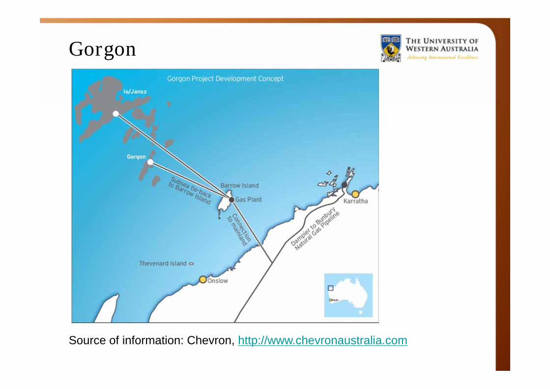
Gorgon
Source of information: Chevron, http://www.chevronaustralia.com
Gorgon
• Led by Chevron• Greater Gorgon Area gas fields• ~ 130 km off the north-west coast of Western Australia
• One of the world's largest natural gas projects • The largest single resource natural gas project in
Australia's history• 15 million tonne per annum (MTPA) Liquefied Natural
Gas (LNG) plant on Barrow Island• domestic gas plant, capacity of 300 terajoules per day
Gorgon
• Important pillar of the Australian economy for > 40 years• Projected AU$64 billion boost to Australia’s Gross
Domestic Product in first 30 years• Direct and indirect employment of around 10,000 people
at peak construction
• ~ 40 trillion cubic feet LNG sufficient power for a city of 1 million people for 800 years
Gorgon
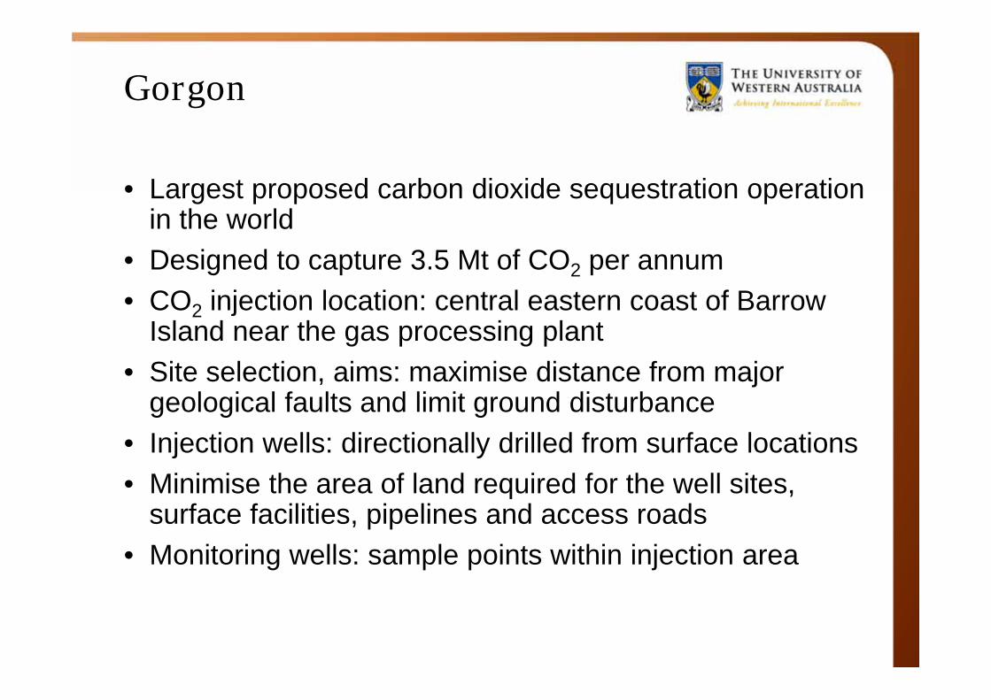
• Largest proposed carbon dioxide sequestration operation in the world
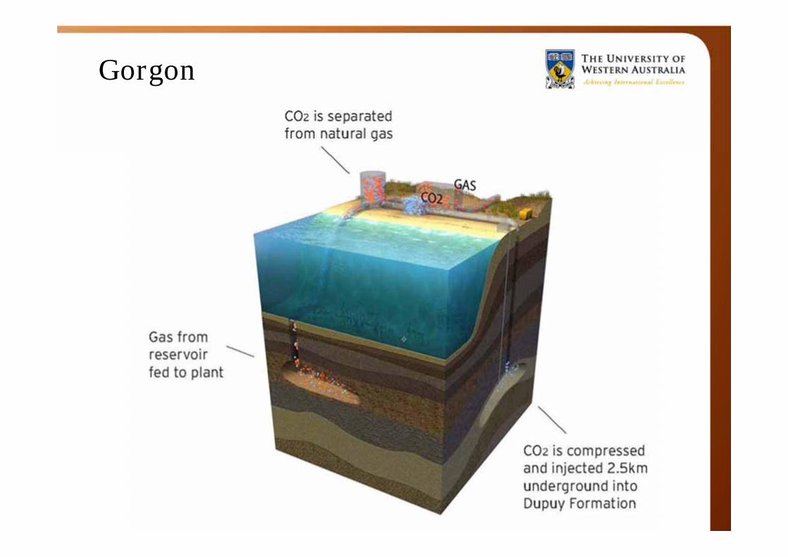
• Designed to capture 3.5 Mt of CO2 per annum• CO2 injection location: central eastern coast of Barrow
Island near the gas processing plant• Site selection, aims: maximise distance from major
geological faults and limit ground disturbance• Injection wells: directionally drilled from surface locations• Minimise the area of land required for the well sites,
surface facilities, pipelines and access roads• Monitoring wells: sample points within injection area
Gorgon
Gorgon
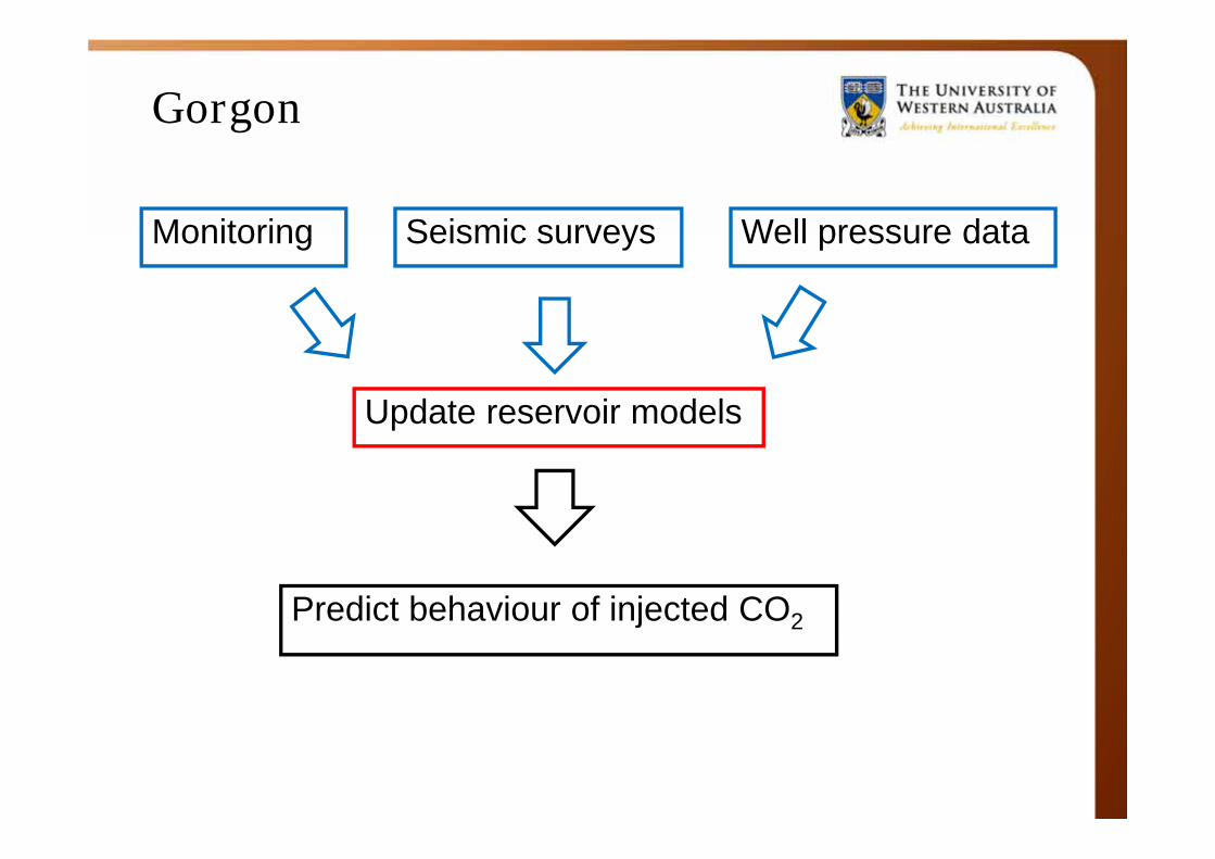
Monitoring Seismic surveys Well pressure data
Update reservoir models
Predict behaviour of injected CO2
Themes
• Examples of carbon sequestration in ocean spaces
–Sleipner West–Gorgon
• Geotechnical considerations in the context of geo-sequestration of CO2 in the offshore environment
• “Ship design”: Mobile jack-up drilling rigs
• Offshore wind energy installation
Geotechnical considerations
IPCC (2005)
Geotechnical considerations
• Geohazards (tectonic activity)
• Soil permeability
• Subsea installations
• Pipeline-soil interaction
• Movements of the seabed due to carbon sequestration Potential impact on soil-structure interaction
of existing or proposed infrastructure
General considerations
• Major concern: effectiveness as climate change mitigation option due to leakage of stored CO2
• IPCC estimate: risks comparable to those associated with current hydrocarbon activity for well-selected, designed and managed geological storage sites
• CO2 could be trapped for millions of years• Well selected storage sites likely to retain over 99% of
injected CO2 over 1000 years• Greater risk: Leakage through the injection pipe
Themes
• Examples of carbon sequestration in ocean spaces
–Sleipner West–Gorgon
• Geotechnical considerations in the context of geo-sequestration of CO2 in the offshore environment
• “Ship design”: Mobile jack-up drilling rigs
• Offshore wind energy installation
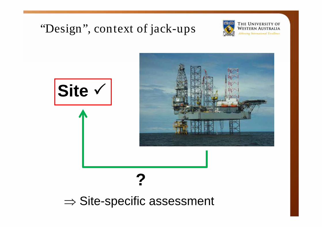
“Design”, context of jack-ups
Site
? Site-specific assessment
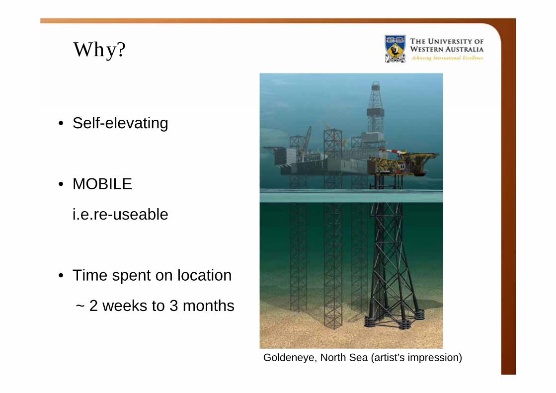
Why?
• Self-elevating
• MOBILE
i.e.re-useable
• Time spent on location
~ 2 weeks to 3 months
Goldeneye, North Sea (artist’s impression)
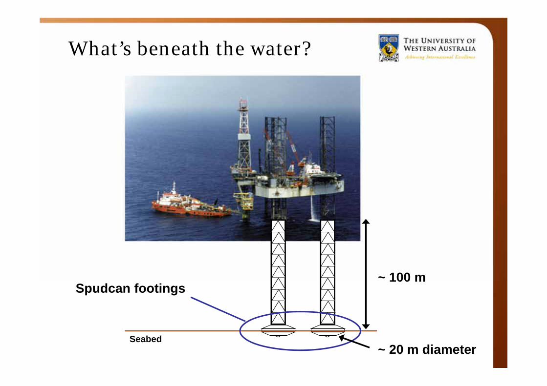
Spudcan footings
Seabed
What’s beneath the water?
~ 100 m
~ 20 m diameter

Risks associated with jack-ups
• In transit– Ship impact, towline failure, flooding, capsize (legs 500 ft
above the water line)• During installation
– High leg impact loads at touchdown, contact with other structures (pipeline, WHP), punch-through, …
• During operation– Punch-through (not necessarily in the clear after
installation!), leg sliding, excessive platform movement, ship impact, wave impact on hull, loss of foundation stability due to scour, rack/pinion failure
Jack-ups tend to be used to their operational and design limits
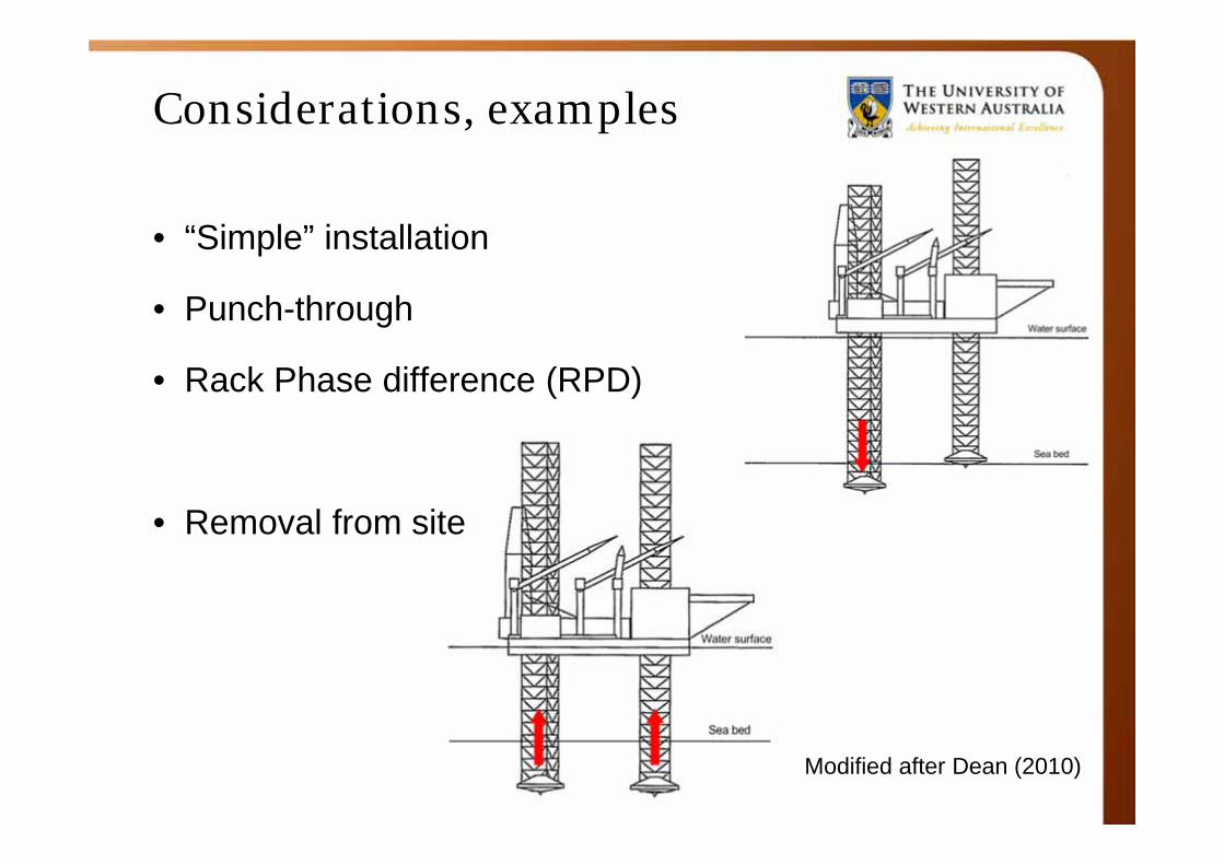
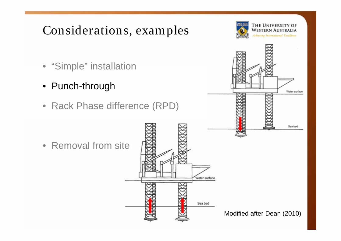
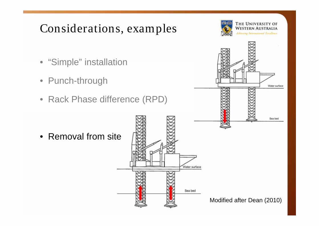
Considerations, examples
• “Simple” installation
• Punch-through
• Rack Phase difference (RPD)
• Removal from site
Modified after Dean (2010)
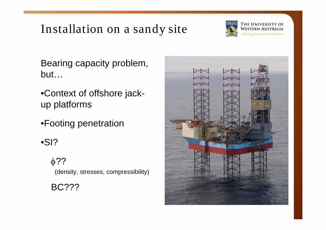
Installation on a sandy site
Bearing capacity problem, but…
•Context of offshore jack-up platforms
•Footing penetration
•SI?
??(density, stresses, compressibility)
BC???

Guidelines
• SNAME (2008)• ISO19905-1
• InSafeJIP: guideline available for download (free)http://insafe.woking.rpsplc.co.uk/download.asp
Primarily aimed at site-specific assessment during operation
Focus on SI workscope and procedures, jack-up installation
Use realistic , account for mobilisation in BC
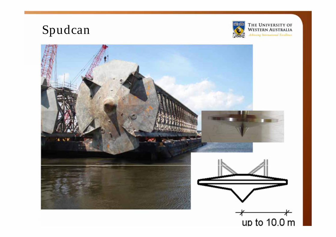
Spudcan
Modified after Dean (2010)
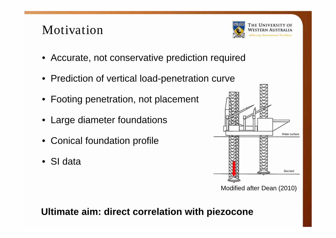
Motivation
• Accurate, not conservative prediction required
• Prediction of vertical load-penetration curve
• Footing penetration, not placement
• Large diameter foundations
• Conical foundation profile
• SI data
Ultimate aim: direct correlation with piezocone
Bearing capacity
• Soil characteristics
• Dense sand -> little penetration
• Soft clay -> larger penetration
(of the order of 20-30 m)
-> soil backflow?
Where is the uncertainty?...
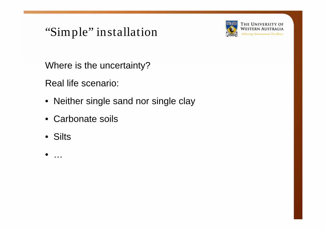
“Simple” installation
Where is the uncertainty?
Real life scenario:
• Neither single sand nor single clay
• Carbonate soils
• Silts
• …
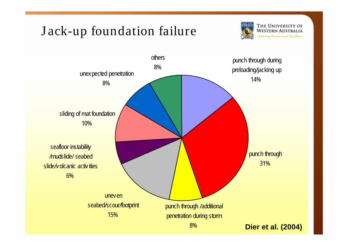
Jack-up foundation failure
punch through 31%
uneven seabed/scour/footprint
15%
sliding of mat foundation 10%
unexpected penetration 8%
others 8%
punch through /additional penetration during storm
8%
seafloor instability /mudslide/ seabed
slide/volcanic activ ities 6%
punch through during preloading/jacking up
14%
Dier et al. (2004)
Considerations, examples
• “Simple” installation
• Punch-through
• Rack Phase difference (RPD)
• Removal from site
Modified after Dean (2010)
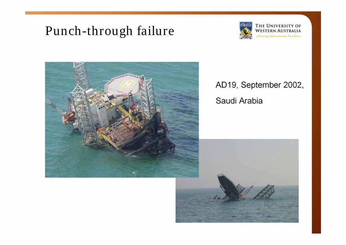
Punch-through failure
AD19, September 2002,
Saudi Arabia
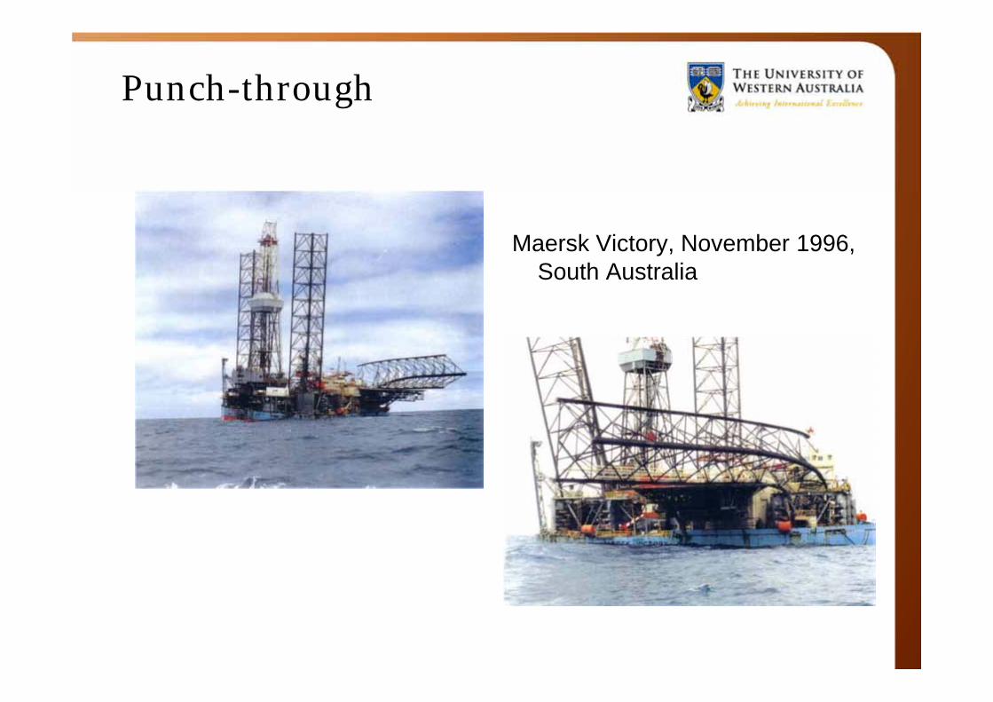
Punch-through
Maersk Victory, November 1996, South Australia
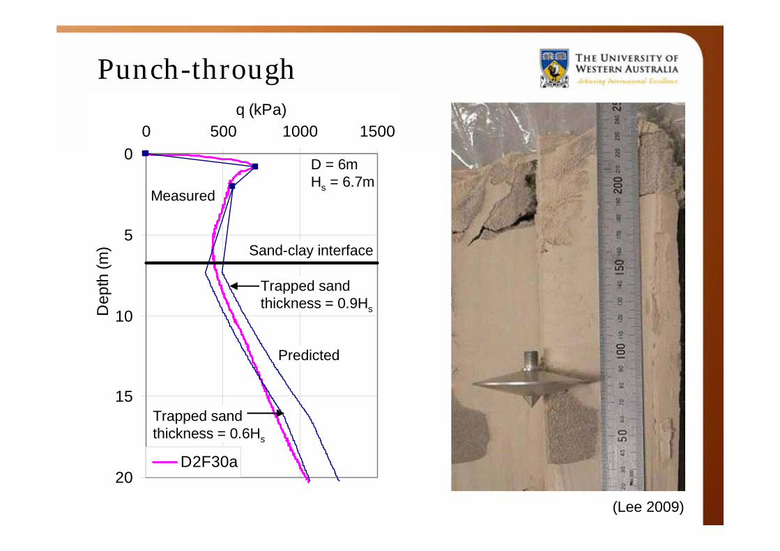
Punch-through
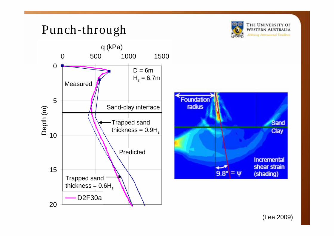
(Lee 2009)
0
5
10
15
20
0 500 1000 1500q (kPa)D
epth
(m)
D2F30a
Measured
Trapped sand thickness = 0.6Hs
D = 6mHs = 6.7m
Trapped sand thickness = 0.9Hs
Sand-clay interface
Predicted
Punch-through
• Uncontrolled
• Structural problems
– Leg bending,• Damage to leg-hull connection,
– Failure of leg element(s),– Lost time, lost revenue, repairs,– Excessive penetration -> legs not long enough– …– Collapse of rig
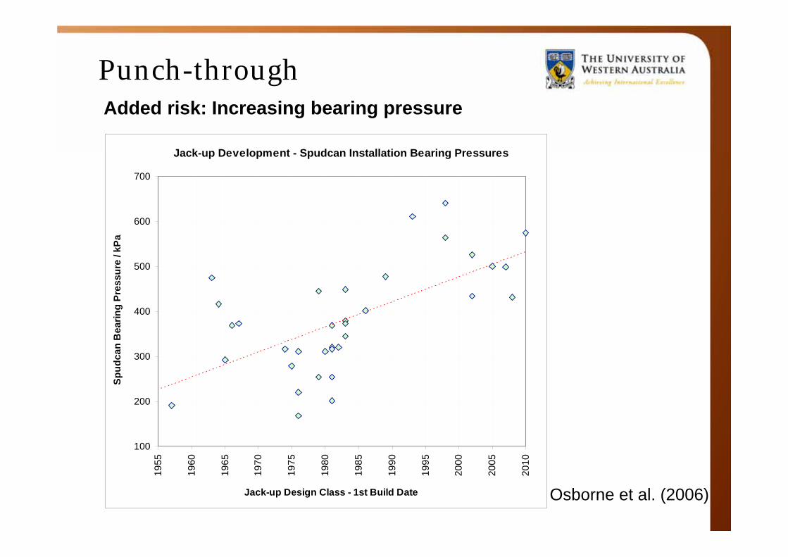
Punch-throughAdded risk: Increasing bearing pressure
Jack-up Development - Spudcan Installation Bearing Pressures
100
200
300
400
500
600
700
1955
1960
1965
1970
1975
1980
1985
1990
1995
2000
2005
2010
Jack-up Design Class - 1st Build Date
Spud
can
Bea
ring
Pres
sure
/ kP
a
Osborne et al. (2006)
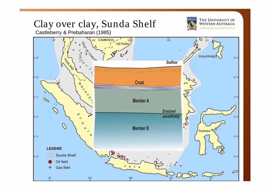
Clay over clay, Sunda Shelf Castleberry & Prebaharan (1985)

Punch-through: Clay over clay Comparison of finite element results with SNAME (2008)
Hossain & Randolph (2010)
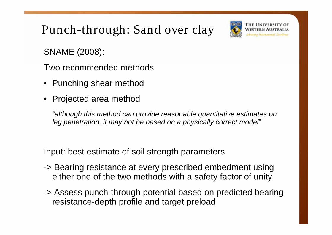
Punch-through: Sand over clay
SNAME (2008):
Two recommended methods
• Punching shear method
• Projected area method
“although this method can provide reasonable quantitative estimates on leg penetration, it may not be based on a physically correct model”
Input: best estimate of soil strength parameters
-> Bearing resistance at every prescribed embedment using either one of the two methods with a safety factor of unity
-> Assess punch-through potential based on predicted bearing resistance-depth profile and target preload
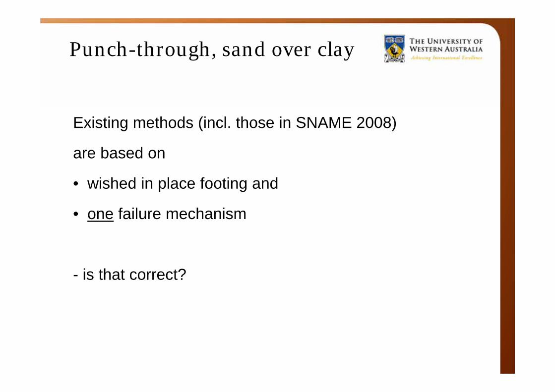
Punch-through, sand over clay
Existing methods (incl. those in SNAME 2008)
are based on
• wished in place footing and
• one failure mechanism
- is that correct?
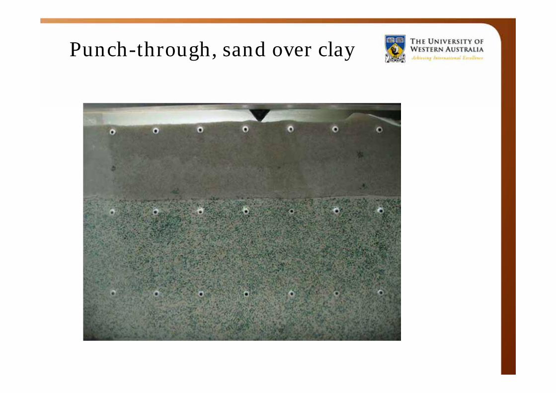
Punch-through, sand over clay
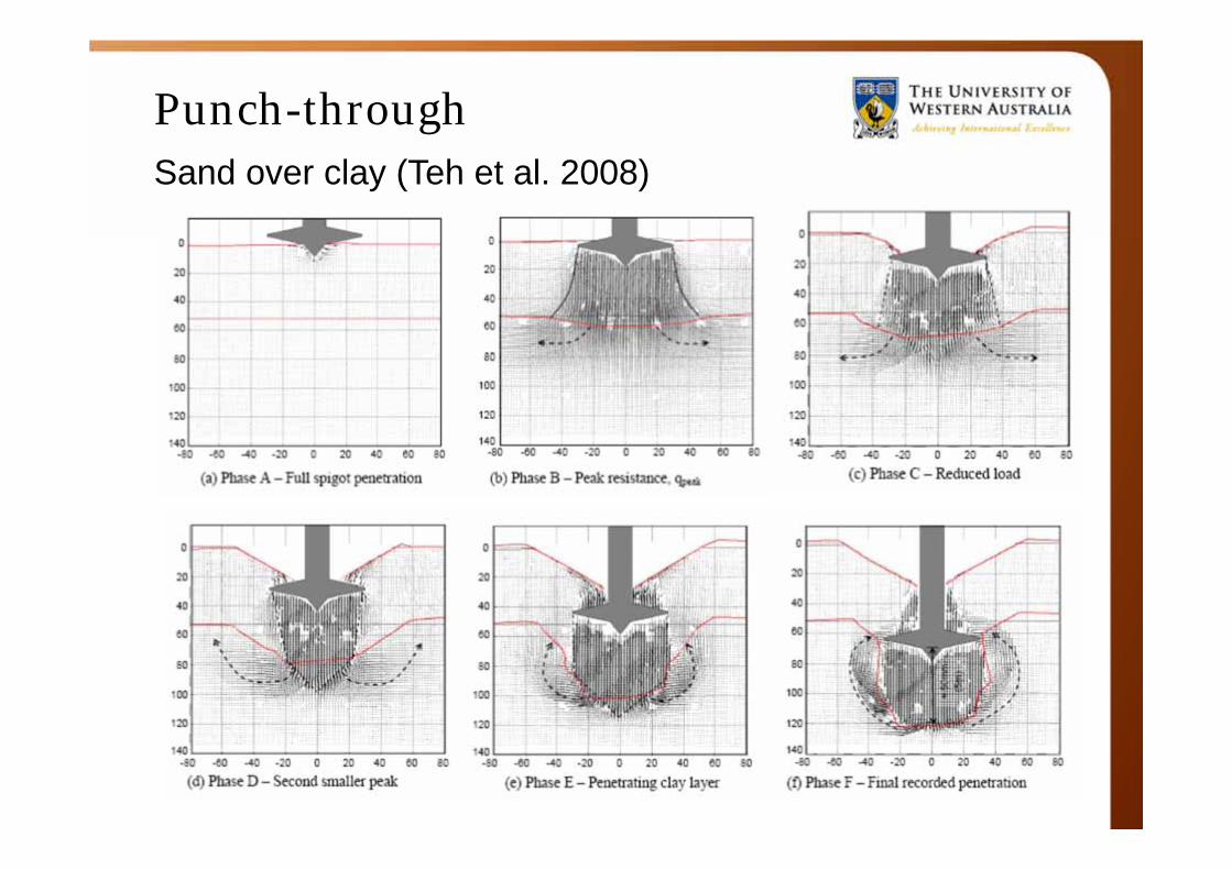
Punch-throughSand over clay (Teh et al. 2008)
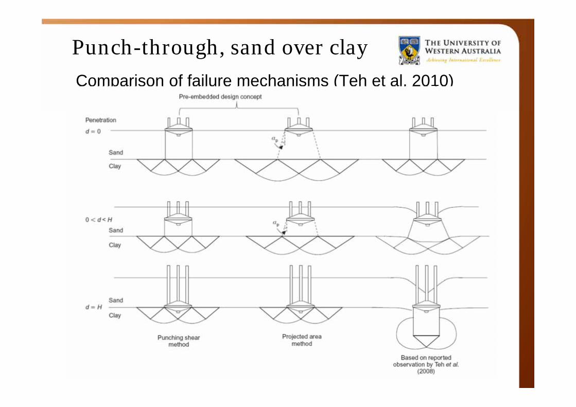
Punch-through, sand over clayComparison of failure mechanisms (Teh et al. 2010)
Punch-through
(Lee 2009)
0
5
10
15
20
0 500 1000 1500q (kPa)D
epth
(m)
D2F30a
Measured
Trapped sand thickness = 0.6Hs
D = 6mHs = 6.7m
Trapped sand thickness = 0.9Hs
Sand-clay interface
Predicted
Recent developmentsPunch-through sand over clayTeh, K.L., Cassidy, M.J., Leung, C.F., Chow, Y.K., Randolph, M.F., Quah, C.K. (2008). Revealing
the bearing failure mechanisms of a penetrating spudcan through sand overlaying clay. Géotechnique. Vol. 58, No. 10, pp. 793-804.
Lee, K.K., Randolph, M.F., Cassidy, M.J. (2009). New simplified conceptual model for spudcan foundations on sand overlying clay soils. Proc. 41st Offshore Technology Conference, Houston, OTC-20012.
Teh, K.L., Leung, C.F., Chow, Y.K., Cassidy, M.J. (2010). Centrifuge model study of spudcan penetration in sand overlying clay. Géotechnique, Vol. 60, No. 11, pp. 825-842.
Punch-through clay over clayHossain, M.S. and Randolph, M.F. (2010). Deep-penetrating spudcan foundations on layered
clays: centrifuge tests. Géotechnique, Vol. 60, No. 3, pp. 157-170.
Hossain, M.S. and Randolph, M.F. (2010). Deep-penetrating spudcan foundations on layered clays: numerical analysis. Géotechnique, Vol. 60, No. 3, pp. 171-184.

Considerations, examples
• “Simple” installation
• Punch-through
• Rack Phase difference (RPD)
• Removal from site
Modified after Dean (2010)
Rack phase difference (RPD)
• What is RPD?
– “Measurable difference in the vertical position of the chords relative to each other within an individual leg”Nowak & Lawson (2005)
– Alerts to potential problems!
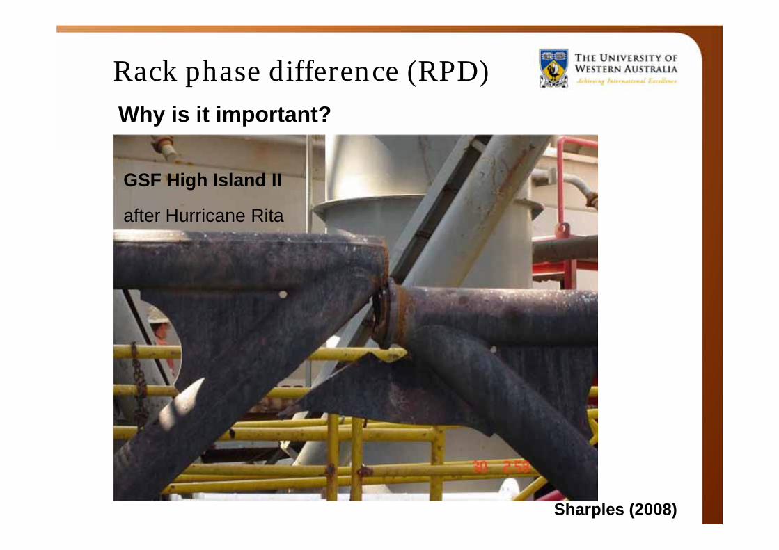
Why is it important?
RPD results in large loads
being transferred to the leg’s
diagonal braces, which might
buckle as a consequence.
Rack phase difference (RPD)
Sharples (2008)
GSF High Island II
after Hurricane Rita
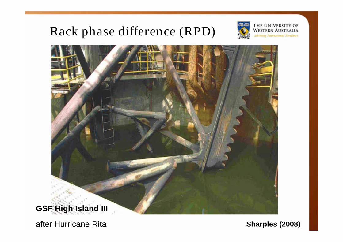
Rack phase difference (RPD)
GSF High Island III
after Hurricane Rita Sharples (2008)
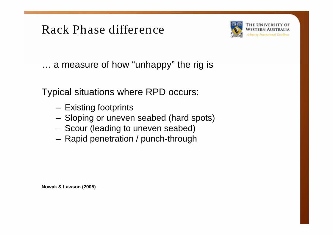
Rack Phase difference
… a measure of how “unhappy” the rig is
Typical situations where RPD occurs:– Existing footprints– Sloping or uneven seabed (hard spots)– Scour (leading to uneven seabed)– Rapid penetration / punch-through
Nowak & Lawson (2005)
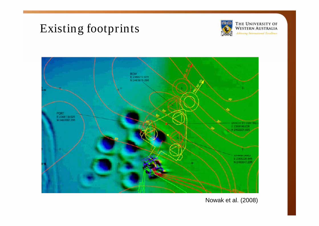
Existing footprints
Nowak et al. (2008)
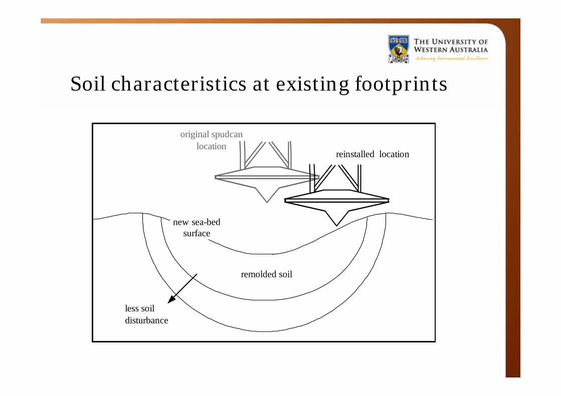
Soil characteristics at existing footprints
original spudcanlocation
reinstalled location
remolded soil
less soildisturbance
new sea-bedsurface
original spudcanlocation
reinstalled location
remolded soil
less soildisturbance
new sea-bedsurface

Soil characteristics at existing footprints Change in sand over clay soil profile (Teh 2006)
Considerations, examples
• “Simple” installation
• Punch-through
• Rack Phase difference (RPD)
• Removal from site
Modified after Dean (2010)
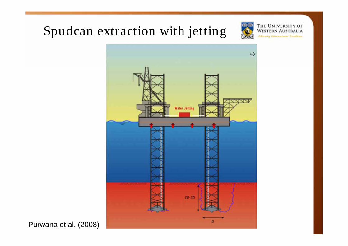
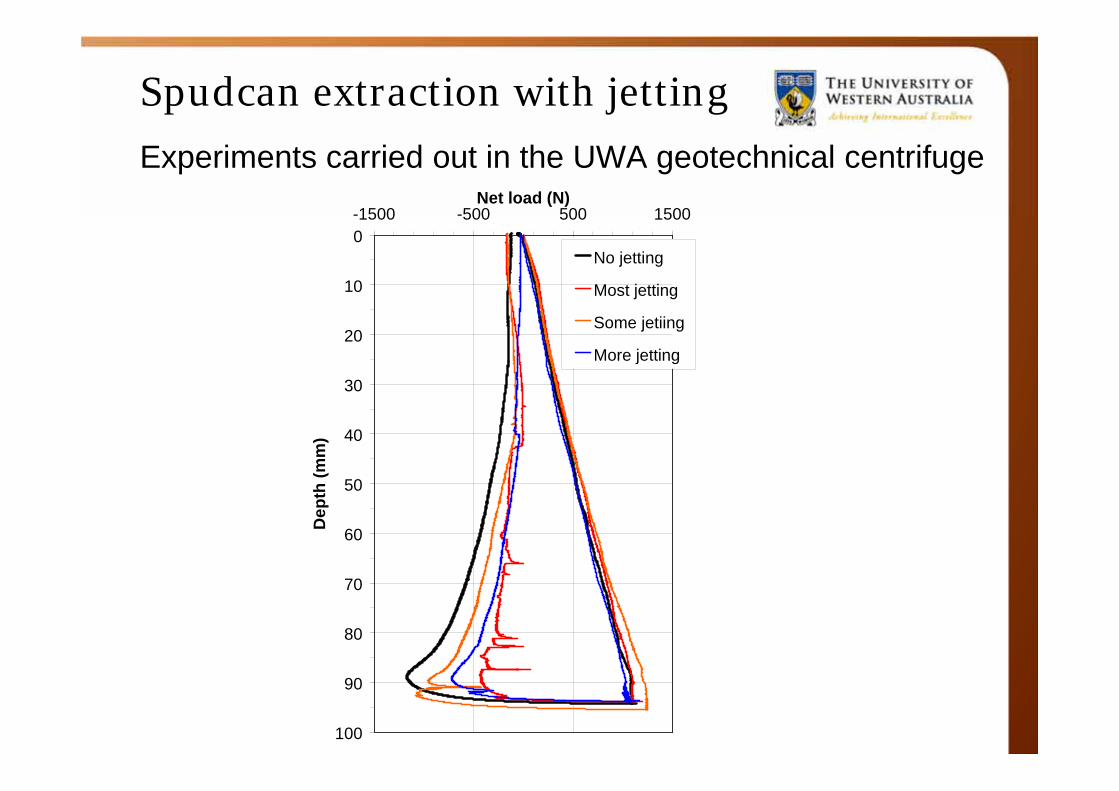
Spudcan extraction with jetting
Purwana et al. (2008)
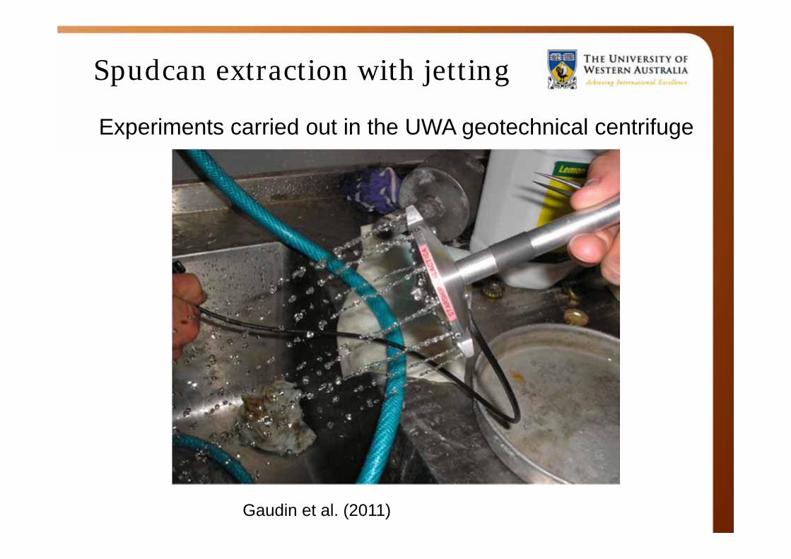
Spudcan extraction with jetting
Experiments carried out in the UWA geotechnical centrifuge
Gaudin et al. (2011)
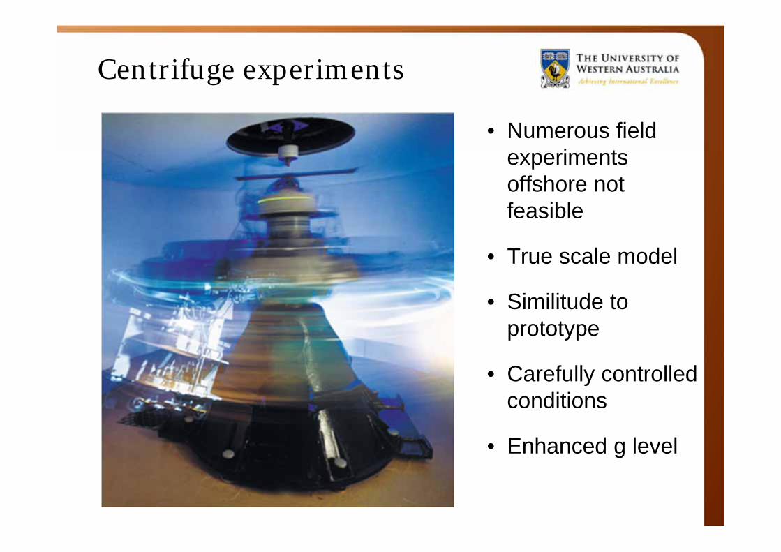
Centrifuge experiments
• Numerous field experiments offshore not feasible
• True scale model
• Similitude to prototype
• Carefully controlled conditions
• Enhanced g level
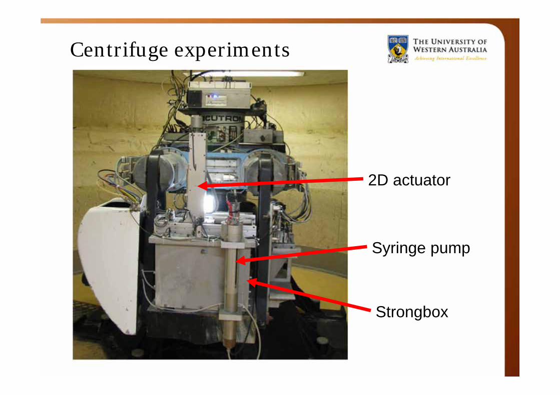
Centrifuge experiments
2D actuator
Syringe pump
Strongbox
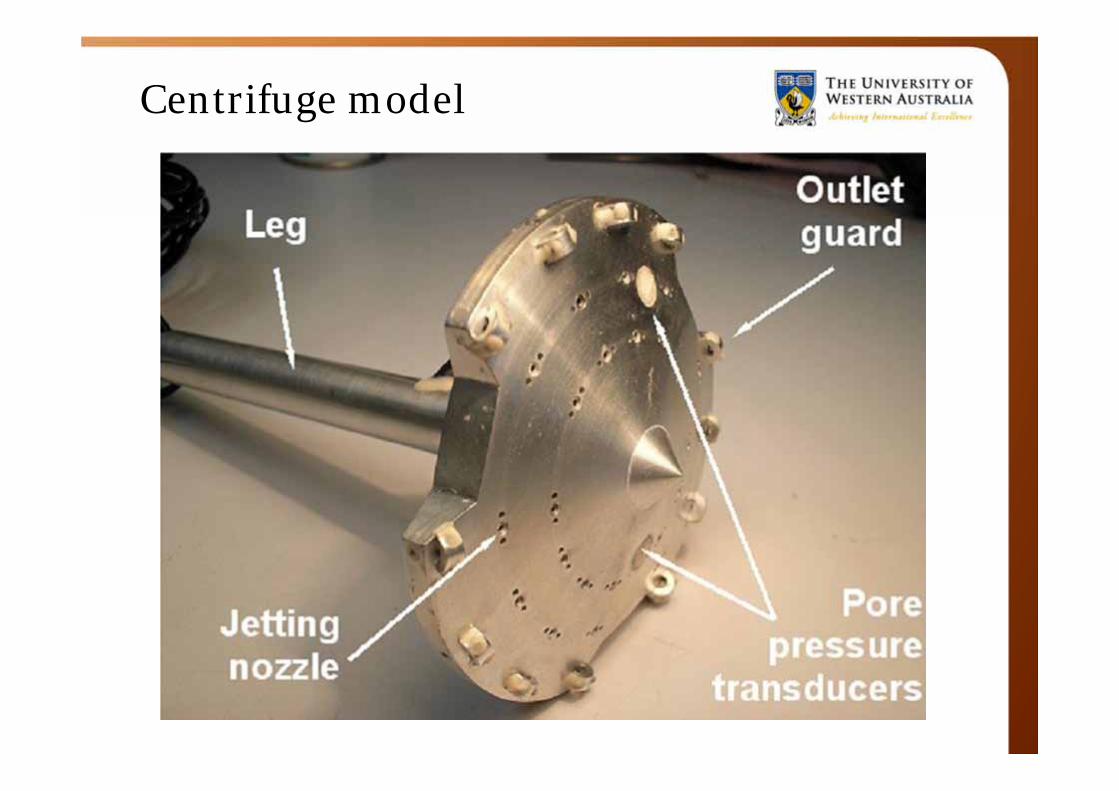
Centrifuge model
Spudcan extraction with jetting Experiments carried out in the UWA geotechnical centrifuge
0
10
20
30
40
50
60
70
80
90
100
-1500 -500 500 1500Net load (N)
Dep
th (m
m)
No jetting
Most jetting
Some jetiing
More jetting
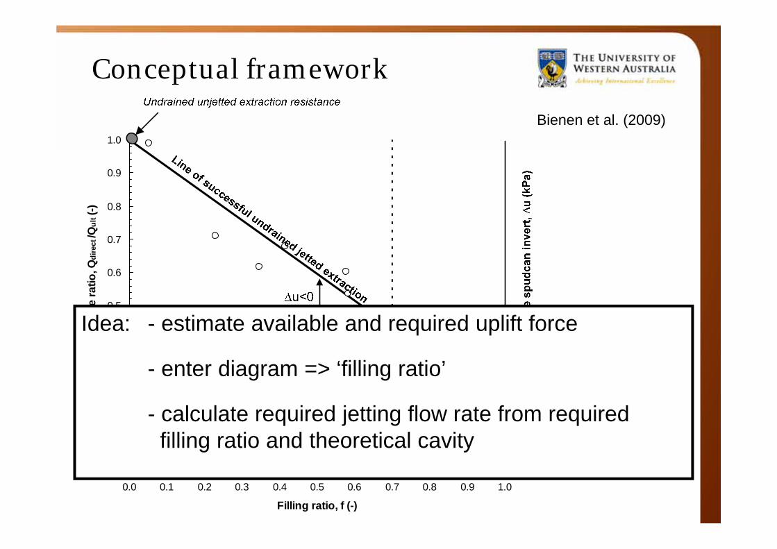
Conceptual framework
0.0
0.1
0.2
0.3
0.4
0.5
0.6
0.7
0.8
0.9
1.0
0.0 0.1 0.2 0.3 0.4 0.5 0.6 0.7 0.8 0.9 1.0
Filling ratio, f (-)
Extra
ctio
n re
sist
ance
ratio
, Qdi
rect
/Qul
t (-)
Idea: - estimate available and required uplift force
- enter diagram => ‘filling ratio’
- calculate required jetting flow rate from required filling ratio and theoretical cavity
Bienen et al. (2009)
Themes
• Examples of carbon sequestration in ocean spaces
–Sleipner West–Gorgon
• Geotechnical considerations in the context of geo-sequestration of CO2 in the offshore environment
• “Ship design”: Mobile jack-up drilling rigs
• Offshore wind energy installation
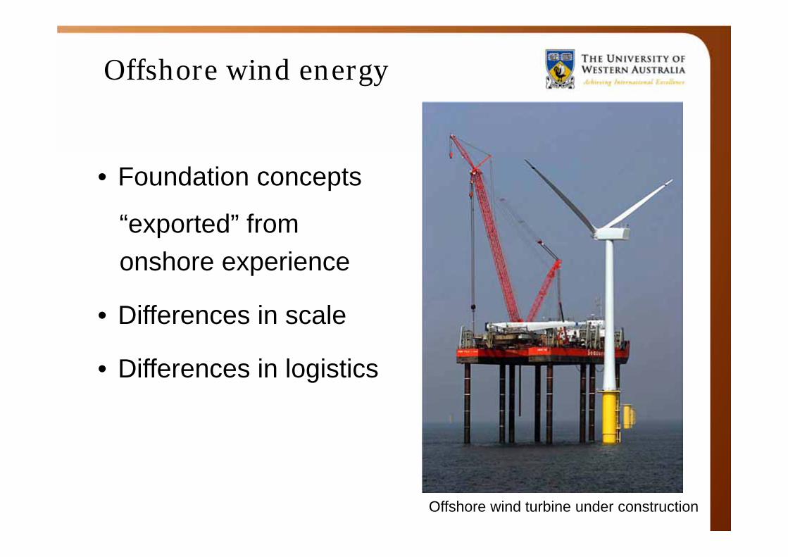
Offshore wind energy
Offshore wind turbine under construction
• Foundation concepts
“exported” fromonshore experience
• Differences in scale
• Differences in logistics
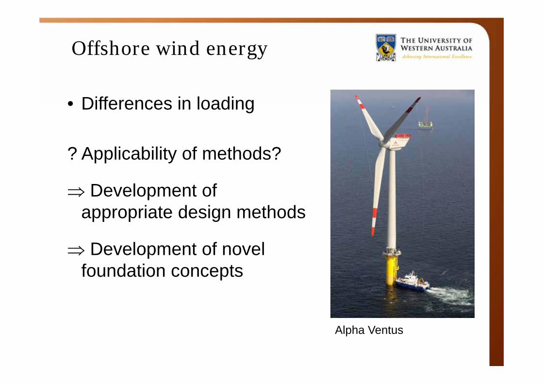
Offshore wind energy
Alpha Ventus
• Differences in loading
? Applicability of methods?
Development of appropriate design methods
Development of novel foundation concepts
Thank you
-
Questions?