geotechnical engineering report - construction...unconfined compression tests unconfined compression...
TRANSCRIPT

Geotechnical Engineering Report
Denton Municipal Electric Hickory Substation
Denton, TX
September 30, 2016


D&S ENGINEERING LABS, LLC Hickory Substation Denton, Texas (13-0278-16)
TABLE OF CONTENTS
1.0 PROJECT DESCRIPTION ...................................................................................... 1
2.0 PURPOSE AND SCOPE ......................................................................................... 1
3.0 FIELD AND LABORATORY INVESTIGATION ....................................................... 2
3.1 General ............................................................................................................. 2
3.2 Laboratory Testing ............................................................................................ 3
Unconfined Compression Tests ............................................................... 3
Overburden Swell Tests ........................................................................... 4
Soil Thermal Resistivity ............................................................................ 4
4.0 SITE CONDITIONS ................................................................................................. 4
4.1 Stratigraphy ....................................................................................................... 4
4.2 Groundwater ..................................................................................................... 5
5.0 SOIL MOVEMENT ANALYSIS ................................................................................ 6
5.1 Estimated Potential Vertical Movement (PVM) ................................................. 6
6.0 FOUNDATION RECOMMENDATIONS .................................................................. 6
6.1 Shallow Foundations – Mats ............................................................................. 6
6.2 Drilled Shaft Foundations – Structures and Equipment .................................... 7
Lateral Load Parameters ......................................................................... 8
6.2.2 Drilled Shaft Construction Considerations ............................................... 9
6.3 Buried Pipe – Underground Transmission ...................................................... 10
Excavations ............................................................................................ 10
7.0 EARTHWORK RECOMMENDATIONS ................................................................. 11
7.1 Soil Subgrade Preparation .............................................................................. 11
7.2 Additional Considerations ............................................................................... 12
8.0 PAVEMENTS AND DRAINAGE ............................................................................ 12
8.1 General ........................................................................................................... 13
8.2 Behavior Characteristics of Expansive Soils Beneath Pavement ................... 13
8.3 Subgrade Strength Characteristics ................................................................. 13
8.4 Rigid Pavement Design and Recommendations ............................................ 14
Pavement Reinforcing Steel .................................................................. 14
Pavement Joints and Cutting ................................................................. 14
8.5 Subgrade Preparation Recommendations ...................................................... 15
Pavement Areas .................................................................................... 15

D&S ENGINEERING LABS, LLC Hickory Substation Denton, Texas (13-0278-16)
Non-Pavement Areas ............................................................................. 16
9.0 GEOLOGIC HAZARDS / SEISMIC CONSIDERATIONS ...................................... 16
10.0 LIMITATIONS ........................................................................................................ 16
APPENDIX A – BORING LOGS AND SUPPORTING DATA
APPENDIX B – THERMAL RESISTIVITY TEST RESULTS
APPENDIX C – GENERAL DESCRIPTION OF PROCEDURES

1
GEOTECHNICAL INVESTIGATION DENTON MUNICIPAL ELETRIC – HICKORY SUBSTATION
DENTON, TEXAS
1.0 PROJECT DESCRIPTION
This report presents the results of the geotechnical investigation for Denton Municipal Electric’s new Hickory electrical substation and underground transmission lines. The project site is located at the southeast corner of West Oak Street and North Bonnie Brae Street in Denton, Texas. The underground transmission lines will be installed near the center of the site and will traverse to the southeast along West Hickory Street, then will turn south beneath Avenue H. The proposed construction will include transformer pads, switchgear and transmission control buildings, and overhead and underground transmission lines. No earth retaining structures are currently planned.
The site has a slight slope to the south. The east side of the proposed substation site is currently undeveloped and covered with short grass and medium height trees. Five residences formerly occupied the west side of the site. One still remained at the time of the field investigation. Photographs showing the condition of the site during the field portion of this investigation are included below.
2.0 PURPOSE AND SCOPE
The purpose of this investigation was to:
Identify the subsurface stratigraphy and groundwater conditions present at the site.
Evaluate the physical and engineering properties of the subsurface conditions for use in the geotechnical analyses.
Provide geotechnical recommendations for use in design of the proposed structures, as well as recommendations for related site work.
The scope of this investigation consisted of:

D&S ENGINEERING LABS, LLC Hickory Substation Denton, Texas (13-0278-16)
2
Drilling and sampling ten (10) borings to depths of about 50 feet below existing grade and one (1) boring to a depth of about 25 feet.
Laboratory testing of selected soil and bedrock samples obtained during the field investigation.
Preparation of a Geotechnical Report that includes:
o Evaluation of Potential Vertical Movement (PVM).
o Recommendations for foundation design.
o Recommendations for earthwork.
3.0 FIELD AND LABORATORY INVESTIGATION
3.1 General
The borings were advanced using a truck-mounted drilling rig, that was equipped with continuous flight augers and wet rotary coring equipment. Undisturbed samples of cohesive soil and weathered bedrock strata were obtained using 3-inch diameter tube samplers that were advanced into the soils in 1-foot increments by the continuous thrust of a hydraulic ram located on the drilling equipment. After sample extrusion, an estimate of the material stiffness of each cohesive soil and weathered bedrock sample was obtained in the field using a hand penetrometer.
The soils and bedrock materials were periodically tested in situ using the Texas Cone penetration tests in order to examine the resistance of the bedrock materials to penetration. For this test, a 3-inch diameter steel cone is driven utilizing the energy equivalent of a 170-pound hammer falling freely from a height of 24 inches and striking an anvil located at the top of the drill string. Depending on the resistance of the bedrock materials, either the number of blows of the hammer required to provide 12 inches of penetration is recorded (as two increments of 6 inches each), or the inches of penetration of the cone resulting from 100 blows of the hammer are recorded (as two increments of 50 blows each).
The bedrock strata present in Borings B1 and B3 through B11 were drilled and sampled using a double-tube core barrel fitted with a tungsten-carbide, saw-tooth bit. The length of core recovered (REC), expressed as a percentage of the coring interval, along with the Rock Quality Designation (RQD), is tabulated at the appropriate depths on the Log of Boring illustrations. The RQD is the sum of all core pieces longer than four inches divided by the total length of the cored interval. Pieces shorter than four inches which were determined to be broken by drilling or by handling were fitted together and considered as one piece.
All samples obtained were extruded in the field, placed in plastic bags to minimize changes in the natural moisture condition, labeled as to appropriate boring number and depth, and placed in protective cardboard boxes for transportation to the laboratory. The samples were described and preserved in the field. The approximate

D&S ENGINEERING LABS, LLC Hickory Substation Denton, Texas (13-0278-16)
3
locations of the borings performed at the site are shown on the boring location map that is included in Appendix A. The specific depths, thicknesses and descriptions of the strata encountered are presented on the individual Boring Log illustrations, which are also included in Appendix A. Strata boundaries shown on the boring logs are approximate.
3.2 Laboratory Testing
Laboratory tests were performed to classify the soil types. The samples recovered during the field exploration were described by a geotechnical engineer in the laboratory. These descriptions were later refined based on results of the laboratory tests performed.
Samples were classified and described, in part, using ASTM and Unified Soil Classification System (USCS) procedures. Bedrock strata were described using standard geologic nomenclature.
In order to determine soil characteristics and to aid in classifying the soils, classification testing was performed on selected samples as requested by the geotechnical engineer. The tests were performed in general accordance with the following test procedures. The classification tests are described in more detail in Appendix B (General Description of Procedures).
Moisture Content ASTM D 2216
Atterberg Limits ASTM D 4318
Percent Passing No. 200 Sieve ASTM D 1140
Additional tests were performed to aid in evaluating soil strength, volume change, and other physical properties, including:
Unconfined Compressive Strength of Soil Samples ASTM D 2166
Overburden Swell Tests
Soil Thermal Resistivity IEEE Standard 442
The results of these tests are presented at the corresponding sample depths on the appropriate Boring Log illustrations presented in Appendix A.
Unconfined Compression Tests
Unconfined compression tests were performed on selected samples of the cohesive soils and weathered limestone with few thin shale seams. These tests were performed in general accordance with ASTM D 2166. For each unconfined compression test performed, a cylindrical specimen was subjected to an axial load applied at a constant rate of strain until failure or a large strain (i.e., greater than 15 percent) occurred.

D&S ENGINEERING LABS, LLC Hickory Substation Denton, Texas (13-0278-16)
4
Overburden Swell Tests
Selected samples of the near-surface cohesive soils were subjected to overburden swell tests. For this test, a sample is placed in a consolidometer and is subjected to the estimated in-situ overburden pressure. The sample is then inundated with water and allowed to swell. Moisture contents are determined both before and after completion of the test. Test results are recorded as the percent swell, with initial and final moisture content.
Soil Thermal Resistivity
Thermal analysis of the subsurface materials was performed on 15 samples of the cohesive soils and weathered limestone within Borings B1, B2, B3, B5 and B11 at depths recommended by Mr. Dennis Johnson (Power Engineers, Inc.). These tests were performed in general accordance with IEEE Standard 442 by Geotherm USA Laboratory. For each thermal resistivity test performed on undisturbed tube samples, a series of thermal resistivity measurements were made in stages, with moisture contents ranging from the natural condition to completely dry condition. The results are presented in Appendix C.
4.0 SITE CONDITIONS
4.1 Stratigraphy
Based upon our examination of the boring samples and a review of the Geologic Atlas of Texas, Sherman Sheet, this site is determined to be in an area characterized by soil and bedrock strata associated with the undivided Grayson Marl and Main Street Limestone Formation.
Pavements were present at the ground surface at Boring locations B1 and B2 advanced in Avenue H. The pavement section consists of about 3-inches of asphalt underlain by 6-inches of aggregate base. The soils beneath the asphalt pavement were tested with a phenolphthalein solution to investigate the presence of lime treatment. These tests did not produce any reactions, indicating that free lime was not present.
Fill materials were encountered at the ground surface within Borings B3 through B11. The fill consists primarily of medium dense, dark brown and reddish brown clayey sand, containing trace amounts of aggregate fragments. The fill extends to depth of approximately 2 to 3 feet below existing site grades.
Below the pavements within Borings B1 and B2 and below the fill soils within Borings B3 through B11, interbedded lean and fat clay soils were encountered. The clay soils are very stiff in consistency, are generally dark brown, reddish brown and light gray in color, and occasionally contain calcareous nodules. These overburden soils extend to the top of weathered limestone bedrock within all 11 borings at depths of about 6 to 12 feet below existing site grades.

D&S ENGINEERING LABS, LLC Hickory Substation Denton, Texas (13-0278-16)
5
Weathered shale bedrock strata were encountered beneath the overburden soils. The weathered shale strata encountered are differentially weathered, having been leached by percolating waters over time. The degree of weathering decreases with depth. The weathered shales are generally very soft to soft in rock hardness, light brown, light gray and tan in color. The weathered shale bedrock strata extends to the top of fresh limestone strata at depths of 22 to 31 feet below existing site grades.
The fresh limestone strata are generally soft to medium hard in rock hardness, light to dark gray in color and contains occasional thin shale seams. The limestone bedrock strata extends to the top of fresh shale at depths of approximately 38 to 49 feet below existing site grades.
The fresh shales are generally soft to medium hard in rock hardness and are dark gray in color. The shale bedrock strata extends to the termination depth of 50 feet within Borings B1 and B3 through B11.
Subsurface conditions at each boring location are described on the individual boring logs in Appendix A. A summary of the borings is presented in Table 1 below.
Table 1. Subsurface Stratigraphy
Boring No. Total Depth Drilled (ft.)
Top of Weathered Shale (ft.)
Top of Fresh Limestone (ft.)
Top of Fresh Shale (ft.)
B1 50 7 21.5 38
B2 25 7 21 NE
B3 50 8.5 25 46
B4 50 8.5 24 43
B5 50 8.5 27 46
B6 50 8.5 28.5 48
B7 50 8 30.5 45
B8 50 11 27 44
B9 50 11 26 45
B10 50 11 28 47.5
B11 50 11 27 45
NE – Not Encountered
4.2 Groundwater
Groundwater seepage was not encountered within the borings prior to the introduction of water for coring purposes, nor at 25-foot depth within Boring B2 during or at the completion of drilling. Groundwater levels should be anticipated to fluctuate with

D&S ENGINEERING LABS, LLC Hickory Substation Denton, Texas (13-0278-16)
6
seasonal and annual variations in rainfall, and may change as a result of development and landscape irrigation. Groundwater cannot be ruled out during construction.
5.0 SOIL MOVEMENT ANALYSIS
5.1 Estimated Potential Vertical Movement (PVM)
Potential Vertical Movement (PVM) was evaluated utilizing a variety of different methods for predicting movement and based on our experience and professional opinion. Movements can be in the form of swell or settlement.
At the time of our field investigation, the near-surface soils were generally found to be dry to very dry in moisture condition. Based upon the results of our analysis and the soil type, the PVM is estimated to range from about 3 to 5 inches. Soil modification will be required to reduce the PVM. Wet, average, dry are relative terms based on moisture content and plasticity.
6.0 FOUNDATION RECOMMENDATIONS
The soils have the potential for significant post-construction vertical movement with changes in soil moisture content. If potential post-construction movements on the order of one inch can be tolerated, a shallow (footing) foundation or mat foundation may be used to support the various structural elements. If post-construction vertical movements on the order of those described cannot be tolerated, consideration should be given to a drilled shaft foundation system. Recommendations for subgrade preparation are described in the Earthwork Section of this report.
Please note that a soil-supported shallow foundation or floor system may experience some vertical movement with changes in soil moisture content. Non-load bearing walls, partitions, and other elements bearing on the floor slab will reflect these movements should they occur. With appropriate design, adherence to good construction practices, and appropriate post-construction maintenance, these potential movements can be reduced.
6.1 Shallow Foundations – Mats
For large equipment pad shallow foundations, we recommend that structural loads be supported on reinforced concrete, monolithic shallow mats founded in properly prepared subgrade soils at a minimum depth of 36 inches below final exterior grades. Mat foundations should be designed using a maximum allowable bearing pressure of 2,500 pounds per square foot when placed on prepared subgrade as described in the Earthwork section of this report. This pressure may be increased to 4,000 psf if placed on compacted aggregate base material that is at least 24 inches thick. We recommend that mat foundations be a minimum of 16 inches thick.
Mat excavations should not be left open overnight. Concrete or engineered fill should be placed the same day that footings are excavated. We recommend that a

D&S ENGINEERING LABS, LLC Hickory Substation Denton, Texas (13-0278-16)
7
representative of D&S observe all footing excavations prior to placing concrete to verify the excavation depth, cleanliness, and integrity of the mat bearing surface. Any mat excavations left open overnight should be observed by D&S prior to placing concrete to evaluate the depth of additional excavation required. In the event that reinforcement and concrete cannot be placed on the day final excavation grades are achieved, the base of the excavation may be deepened slightly and covered by a thin seal slab of lean concrete or flowable fill to protect the integrity of the foundation bearing material.
The bottom of all mat excavations should be free of any loose or soft material prior to the placement of concrete. All equipment pads should be adequately reinforced to minimize cracking as noted movements may occur in the foundation soils.
6.2 Drilled Shaft Foundations – Structures and Equipment
New building structures at the substation will likely consist of either conventional ground-up construction, or of prefabricated metal buildings erected on pier-supported steel frames suspended above the ground surface. For these structures, we recommend a minimum clear space of 6 inches be provided between the bottoms of grade beams or steel frames, and the final ground surface. Any appurtenances connected to the buildings should be pier-supported and should also be isolated from the ground surface by means of a void space.
Structural cardboard forms may be used to provide the required voids beneath the grade beams or appurtenances for building structures. If carton forms are used, care should be taken to assure that the void boxes are not allowed to become wet or crushed prior to or during concrete placement and finishing operations. We recommend that masonite (1/4” thick) or other protective material be placed on top of the carton forms to reduce the risk of crushing the cardboard forms during concrete placement and finishing operations. We recommend using side retainers to prevent soil from infiltrating the void space.
The structural loads for new movement-sensitive building structures or other elements at the substation may be supported on auger-excavated, straight-sided, reinforced concrete drilled shafts founded in the fresh gray and dark gray limestone encountered at depths of about 21 to 31 feet below existing site grades. Straight-sided drilled piers for structural loads should be a minimum of 18-inches in diameter and penetrate a minimum of 2 feet into the limestone. These piers should be designed for an allowable end-bearing pressure of 50,000 pounds per square foot (psf) and an allowable side friction of 10,000 psf.
The shafts should be provided with sufficient steel reinforcement throughout their length to resist potential uplift pressures that will be exerted. For the near surface soils, these pressures are approximated to be on the order of 1,200 pounds psf of shaft area over an average depth of 10 feet. Often, 1/2 of a percent of steel by cross-sectional area is sufficient for this purpose (ACI 318). However, the final amount of

D&S ENGINEERING LABS, LLC Hickory Substation Denton, Texas (13-0278-16)
8
reinforcement required should be determined based on the information provided herein, and should be the greater of that determination, or ACI 318.
There is no reduction in allowable capacities for shafts in proximity to each other. However, for a two-shaft system, there is an 18 percent reduction in the available perimeter area for side friction capacity for shafts in contact (tangent). The area reduction can be extrapolated linearly to zero at one shaft diameter clear spacing. Please contact this office if other close proximity geometries need to be considered. We anticipate that a straight-side drilled pier foundation system designed and constructed in accordance with the information provided in this report should limit potential settlement to small fractions of an inch.
Lateral Load Parameters
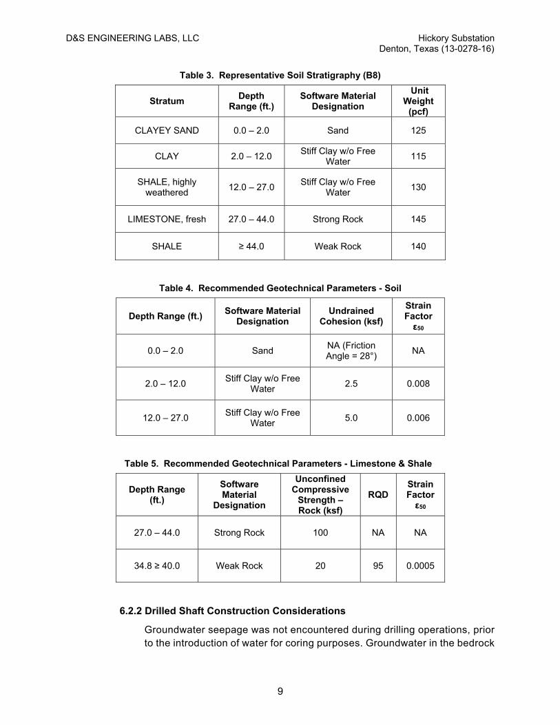
The general subsurface stratigraphic section for this project is approximated by Boring B8. This stratigraphic section was selected to conservatively approximate the subsurface conditions across the site. Many of these parameters are common among various brands of commercial lateral load analysis software. Those shown are used in the software program LPILE 2012®. If needed, other parameters not shown will be provided upon request.
The geotechnical parameters recommended for tower shaft design for the various strata present were conservatively selected to account for observed strata variability. Many of the geotechnical input parameters are common among various brands of commercial lateral load analysis software. Those shown are used in the software program LPILE 2012®. If needed, other parameters not shown may be provided upon request. In view of the nature and characteristics of the materials present, we recommend that the lateral resistance parameters be neglected for the uppermost 2 feet of soil materials to account for seasonal and annual cyclic variations in soil desiccation and contraction, and potential future erosion. However, unit weight in this zone can be considered in design, and the lateral loads may be resolved at the top of the ground surface.
Table 2. Recommended Geotechnical Parameters – Soil & Weathered Shale
Boring Material
Software Material
Designation
Effective Unit Weight
(pcf)
Undrained Cohesion
(psf)
Friction Angle
Strain Factor, ε50
Soil modulus,
k (pci)
Sand (SC) Sand 125 NA 28° NA 90
CLAY (CL) Stiff Clay w/o Free Water
125 1,000 NA 0.007 NA
SHALE, weathered
Weak Rock 130 4,000 NA 0.004 NA
D&S ENGINEERING LABS, LLC Hickory Substation Denton, Texas (13-0278-16)
9
Table 3. Representative Soil Stratigraphy (B8)
Stratum Depth
Range (ft.) Software Material
Designation
Unit Weight
(pcf)
CLAYEY SAND 0.0 – 2.0 Sand 125
CLAY 2.0 – 12.0 Stiff Clay w/o Free
Water 115
SHALE, highly weathered
12.0 – 27.0 Stiff Clay w/o Free
Water 130
LIMESTONE, fresh 27.0 – 44.0 Strong Rock 145
SHALE ≥ 44.0 Weak Rock 140
Table 4. Recommended Geotechnical Parameters - Soil
Depth Range (ft.) Software Material
Designation Undrained
Cohesion (ksf)
Strain Factor ε50
0.0 – 2.0 Sand NA (Friction Angle = 28°)
NA
2.0 – 12.0 Stiff Clay w/o Free
Water 2.5 0.008
12.0 – 27.0 Stiff Clay w/o Free
Water 5.0 0.006
Table 5. Recommended Geotechnical Parameters - Limestone & Shale
Depth Range (ft.)
Software Material
Designation
Unconfined Compressive
Strength – Rock (ksf)
RQD Strain Factor ε50
27.0 – 44.0 Strong Rock 100 NA NA
34.8 ≥ 40.0 Weak Rock 20 95 0.0005
6.2.2 Drilled Shaft Construction Considerations
Groundwater seepage was not encountered during drilling operations, prior to the introduction of water for coring purposes. Groundwater in the bedrock

D&S ENGINEERING LABS, LLC Hickory Substation Denton, Texas (13-0278-16)
10
materials, if present, will be contained within the bedrock joints, fractures, and other rock mass defects. Where these are well-connected and then penetrated, appreciable amounts of water may be produced. Groundwater levels may fluctuate over time in response to cyclical weather variations. In the event that excessive groundwater seepage is encountered during pier installation that cannot be controlled with conventional pumps, sumps, or other means, casing or slurry methods may become necessary.
The installation of all drilled piers should be observed by experienced geotechnical personnel during construction to verify compliance with design assumptions including: 1) verticality of the shaft excavation, 2) identification of the bearing stratum, 3) minimum pier diameter and depth, 4) correct amount of reinforcement, 5) proper removal of loose material, and 6) that groundwater seepage, if encountered, is properly controlled. D&S would be pleased to provide these services in support of this project.
During construction of the drilled shafts, care should be taken to avoid creating an oversized cap ("mushroom") near the ground surface that is larger than the shaft diameter. These “mushrooms” provide a resistance surface that near-surface soils can heave against. If near-surface soils are prone to sloughing, a condition which can result in “mushrooming”, the tops of the shafts should be formed in the sloughing soils using cardboard or other circular forms equal to the diameter of the shaft.
Concrete used for the shafts should have a slump of 8 inches ± 1 inch. Individual shafts should be excavated in a continuous operation and concrete should be placed as soon as after completion of the drilling as is practical. All pier holes should be filled with concrete within 8 hours after completion of drilling. In the event of equipment breakdown, any uncompleted open shaft should be backfilled with soil to be redrilled at a later date. This office should be contacted when shafts have reached the target depth but cannot be completed.
6.3 Buried Pipe – Underground Transmission
We understand new underground transmission structures will be constructed along Avenue H from the southeast corner of the new substation site. Depths of the new lines are not expected to exceed 15 feet.
Excavations
Excavations performed during site underground transmission construction operations in soil or weathered shale should not be difficult and should only require use of normal construction equipment. These excavations are not expected to reach limestone strata.
Excavations greater than 5 feet in height/depth should be in accordance with OSHA 29CFR 1926, Subpart P. The site clay soils and weathered shale

D&S ENGINEERING LABS, LLC Hickory Substation Denton, Texas (13-0278-16)
11
should be assumed to be type “C” soil. The contractor’s OSHA “competent person” should make these determinations in the field during construction. Please note that the existing clays and weathered shales will become slippery if groundwater seepage occurs, or after rain events. This can make working within the excavation difficult.
EARTHWORK RECOMMENDATIONS
The near-surface soils have potential for appreciable post-construction vertical movement with changes in subsurface soil moisture content. Subgrade preparation should provide a relatively uniform material that is at least three (3) feet thick beneath all footings and floor slabs. We have the following recommendations for subgrade preparation to reduce PVM.
7.1 Soil Subgrade Preparation
In order to reduce Potential Vertical Movements for soil-supported structures, we have the following recommendations for subgrade preparation.
Strip the site of all vegetation and remove any remaining organic or deleterious material, including all tree stumps and root balls of existing trees under areas that will be covered with structures and pavements.
After stripping the site, perform any required cuts
After excavating, and prior to the placement of any grade-raise fill across non-paved areas, scarify, rework, and recompact the upper 12 inches of the exposed subgrade soils. The soils should be compacted to between 93 and 98 percent of the maximum density as determined by ASTM D 698 (Standard Proctor), and to at least plus three (+3) percentage points above its optimum moisture content.
Grade raise fill should be placed in layer-compacted lifts not exceeding 8 inches in compacted thickness. These fills should be compacted to between 93 and 98 percent of the maximum density as determined by ASTM D 698 (Standard Proctor), and to at least plus three (+3) percentage points above its optimum moisture content.
After the overall site has been brought to grade, excavate equipment pad areas to a minimum depth of three (3) feet below the bottom of mat foundations (about six (6) to seven (7) feet below final exterior grade). The excavated materials may be stockpiled for future reuse. Excavations should extend at least to the exterior mat dimensions and then extend up to the ground surface at a slope no steeper than 1:Horizontal to 1:Vertical.
Place geogrid across bottom and up the sides of the pad excavations to at least the bottom of mat elevation. Geogrid may be either Tensar BX-1100 or Triax 160, or approved equivalent.

D&S ENGINEERING LABS, LLC Hickory Substation Denton, Texas (13-0278-16)
12
Place the stockpiled excavated soil to the bottom of mat elevation in maximum 8-inch thick compacted lifts. The reworked on-site fill should be compacted to between 93 and 98 percent of the maximum density as determined by ASTM D 698 (Standard Proctor), and to at least plus three (+3) percentage points above its optimum moisture content.
In lieu of on-site soil replacement, select fill may be placed above the geogrid in compacted lifts to the bottom of mat elevation. Select fill should have a liquid limit less than 35 and a plasticity index between 6 and 18, should be essentially free of organic materials and particles in excess of 4 inches their maximum direction, and should have not less than 30 percent material passing a No. 200 mesh sieve. The select fill should be placed in maximum 6-inch thick compacted lifts and compacted to at least 95 percent of the maximum Standard Proctor density and within three (-3 to +3) percentage points of its optimum moisture content.
Alternatively, aggregate base or recycled concrete meeting the gradation, plasticity, and durability requirements of TxDOT Standard Specification Item 247, Type A, Grade 2 or better may be used to re-establish subgrade elevation, and should be placed in maximum 8-inch thick compacted lifts and should be compacted to at least 95 percent of the maximum Standard Proctor density. For recycled concrete, the Type D requirements specified in Item 247 for those materials should be met as well.
Backfill around the equipment pad containment walls above the reworked on-site soil, select fill, or aggregate base pad fill should be clay soils with a Plasticity index greater than 25.
Backfill should be placed in maximum 8-inch compacted lifts and should be compacted to a minimum of 95 percent of the maximum density as determined by ASTM D 698 (Standard Proctor), and to its optimum moisture content or above.
Each lift of fill or backfill should be tested for moisture content and compaction by a testing laboratory with a minimum of 3 tests per lift.
7.2 Additional Considerations
In order to minimize the potential for post-construction vertical movement, consideration should be given to the following:
Final subgrade should slope away from the foundations to the maximum degree possible, with a minimum of 5 percent in the first 5 feet, if practical.
Water should not be allowed to pond next to foundations.
8.0 PAVEMENTS AND DRAINAGE
We understand that final site work will consist of a concrete paved “partial perimeter road” around the north sides of the substation. We anticipate that other surface areas not

D&S ENGINEERING LABS, LLC Hickory Substation Denton, Texas (13-0278-16)
13
covered with structures, equipment, or pavement will receive a covering of free-draining gravel / crushed stone approximately 6 to 8 inches in thickness. The site grading plan indicates that the final subgrade will be shaped to provide a positive slope away from the center of the substation, with ultimate sheet drainage offsite to the west, with an ultimate total fall of about 11 to 12 feet.
Considering the existing subsurface conditions, the earthwork recommendations presented previously, and the foregoing discussion, our recommendations for pavements are presented in subsequent paragraphs.
8.1 General
The pavement designs given in this report are based upon the geotechnical information developed during this study and design criteria assumptions based on conversations with Denton Municipal Electric personnel and the design team. The pavement designs shown below were produced considering the pavement design practices for rigid pavements, the guidelines and recommendations of the American Concrete Pavement Association (ACPA) as well as our experience and professional opinion. However, the Civil Engineer-of-Record should produce the final pavement design and all associated specifications for the project.
8.2 Behavior Characteristics of Expansive Soils Beneath Pavement
Soils for this site are considered to be slightly expansive and may have the potential for volume change with changes in soil moisture content. The moisture content can be maintained to some degree in these soils by covering them with an impermeable surface such as pavement areas. However, if moisture is introduced to the subgrade soils by surface or subsurface water, poor drainage, addition of excessive rainfall after periods of no moisture, or removed by desiccation, the soils can swell or shrink significantly, resulting in distress to pavements in contact with the soil in the form of cracks and displacements. The edges of pavements are particularly prone to moisture variations, and these areas often experience the most distress (cracking).
In order to minimize the negative impacts of expansive soil on pavement areas and improve the long term performance of the pavement, we have the following recommendations:
If possible, provide an elevated pavement which provides the maximum practical drainage away from the pavement (a minimum of 5% slope for the first 5 feet, and preferably 10 feet away from the pavement is suggested)
Avoid long areas of low slope roadway. Adjust slopes to account for the Potential Vertical Movement.
8.3 Subgrade Strength Characteristics
Based on the testing from the investigation and support characteristics after performing the recommended subgrade soil preparation, we recommend using a

D&S ENGINEERING LABS, LLC Hickory Substation Denton, Texas (13-0278-16)
14
California Bearing Ratio (CBR) value of 3 for the pavement section design. A corresponding resilient modulus of 4,500 psi may also be used. We also recommend a Modulus of Subgrade Reaction (k) of 100 pounds per cubic inch (pci) for the subgrade soils (300 pci if pavement is placed over aggregate base).
8.4 Rigid Pavement Design and Recommendations
With the understanding that heavy equipment may periodically access the substation sites, we recommend that Portland Cement Concrete Pavement for this site have a minimum thickness of 6 inches. We have the following concrete mix design recommendations:
Recommended minimum design compressive strength: 3,500 psi with nominal aggregate size no greater than 1 inch.
15 to 20 percent flyash may be used with the approval of the Civil Engineer of record.
Curing compound should be applied within one hour of finishing operations.
Pavement Reinforcing Steel
Due to the absence of specific traffic loading and design life parameters, but understanding that heavy equipment will be periodically accessing the site we recommend that a minimum of 0.2% of steel be used for all concrete pavement sections. This is approximately the equivalent of #4 bars at 16” on center each way for a 6-inch thick concrete pavement. Areas with less severe loading may perform adequately with less reinforcement. Please contact this office once specific traffic loading data is available if additional pavement analyses are desired. Reinforcement chairs should be used beneath all pavement such that the reinforcement is placed one-third (T/3) of the pavement thickness from the top of the pavement using metal or plastic chairs.
Pavement Joints and Cutting
The performance of concrete pavement depends to a large degree on the design, construction, and long term maintenance of concrete joints. The following recommendations and observations are offered for consideration by the Civil Engineer and/or pavement Designer-of-Record:
Contraction joints (sawcuts) should have a spacing of about 30 times the pavement thickness each way, with a maximum spacing of about 15 to 20 feet. Note that tighter sawcut spacing will control contraction cracking better than a wider spacing, and a spacing of about 12 feet is considered very satisfactory.

D&S ENGINEERING LABS, LLC Hickory Substation Denton, Texas (13-0278-16)
15
Sawcuts should be completed as soon as practicable after surface finishing, typically within a few hours after concrete placement, preferably within a maximum of 10 to 12 hours after placement.
Joints should be cleaned and sealed as soon as possible after concrete placement to avoid infiltration of water, sediment, etc. into the open joint and possibly negatively impacting the subgrade. To be most effective, joint sealing should be performed preferably within a day or two.
8.5 Subgrade Preparation Recommendations
Pavement Areas
For the subgrade preparation beneath pavement, we recommend the following:
Strip the site of all vegetation to a minimum depth of 6-inches below existing grades and remove any remaining organic or deleterious material under the planned paved areas, including all tree stumps and root balls of existing trees.
Perform any required cuts
After stripping and cutting, and prior to the placement of any grade-raise or re-work fill, scarify, rework, and recompact the exposed excavated or stripped subgrade to a depth of 12 inches. The scarified and re-worked soils should be compacted to at least 95 percent of the maximum dry density, as determined by ASTM D 698 (standard Proctor), and placed at a moisture content that is within two (+/-2) percentage points of the optimum moisture content, as determined by the same test.
Fill as needed to required pavement subgrade elevation. In areas to receive fill, the fill should be placed in maximum 6-inch compacted lifts, compacted to at least 95 percent of the maximum dry density, as determined by ASTM D 698 (standard Proctor), and placed at a moisture content that is within two (+/-2) percentage points of the optimum moisture content, as determined by the same test. Fill materials may be derived from on-site or may be imported as long as the materials are essentially free of organic materials and particles in excess of 4 inches their maximum direction. Imported fill material should have not less than 35 percent material passing a No. 200 mesh sieve and a Plasticity Index of no more than 30.
Field density and moisture content testing for the roadway should be performed at the rate of one test per 300 linear feet.

D&S ENGINEERING LABS, LLC Hickory Substation Denton, Texas (13-0278-16)
16
Non-Pavement Areas
We anticipate that non-paved areas within the substation footprint will receive about 6 to 8 inches of crushed stone over the prepared subgrade. For these areas, we recommend the following:
After the site has been brought to grade in accordance with the Earthwork Section of this report, place a geotextile “filer fabric” between the subgrade soil and the crushed stone to prevent soil migration into the stone
Place crushed stone around the paved areas as shown on the plans.
9.0 GEOLOGIC HAZARDS / SEISMIC CONSIDERATIONS
North central Texas is generally regarded as an area of low seismic activity. Based on the data developed, and considering the geologic conditions present, we recommend that IBC Soil Site Class “C” be used at this site. The acceleration values below were interpolated from published U.S. Geological Survey National Seismic Hazard Maps.
Table 6. Seismic Design Parameters
Design Parameters Values
Site Class C
Spectral Acceleration for 0.2 sec Period, Ss (g) 0.111
Spectral Acceleration for 1.0 sec Period, S1 (g) 0.054
Site Coefficient for 0.2 sec Period, Fa 1.2
Site Coefficient for 1.0 sec Period, Fv 1.7
10.0 LIMITATIONS
The professional geotechnical engineering services performed for this project, the findings obtained, and the recommendations prepared were accomplished in accordance with currently accepted geotechnical engineering principles and practices.
Variations in the subsurface conditions are noted at the specific boring locations for this study. As such, all users of this report should be aware that differences in depths and thicknesses of strata encountered can vary between the boring locations. The number and spacing of the exploration borings were chosen to obtain geotechnical information for the design and construction of lightly to moderately--loaded structure foundations. Statements in the report as to subsurface conditions across the site are extrapolated from the data obtained at the specific boring locations. If there are any conditions differing significantly from those described herein, D&S should be notified to re-evaluate the recommendations contained in this report.

D&S ENGINEERING LABS, LLC Hickory Substation Denton, Texas (13-0278-16)
17
Recommendations contained herein are not considered applicable for an indefinite period of time. Our office must be contacted to re-evaluate the contents of this report if construction does not begin within a one-year period after completion of this report.
The scope of services provided herein does not include an environmental assessment of the site or investigation for the presence or absence of hazardous materials in the soil, surface water, or groundwater.
All contractors referring to this geotechnical report should draw their own conclusions regarding excavations, construction, etc. for bidding purposes. D&S is not responsible for conclusions, opinions or recommendations made by others based on these data. The report is intended to guide preparation of project specifications and should not be used as a substitute for the project specifications.
Recommendations provided in this report are based on our understanding of information provided by the Client to us regarding the scope of work for this project. If the Client notes any differences, our office should be contacted immediately since this may materially alter the recommendations.

APPENDIX A - BORING LOGS AND SUPPORTING DATA

P16
P15
P14
P12
B1
Ave
H
W Hickory St
B3
B5
B4
B8
B7
B6
B9
B10
B11
B2
N B
on
nie
B
ra
e S
t
W Oak St

KEY TO SYMBOLS AND TERMS
CONSISTENCY: FINE GRAINED SOILS
CONDITION OF SOILS
SECONDARY COMPONENTS
WEATHERING OF ROCK MASS
TCP (#blows/ft)
< 88 - 20
20 - 6060 - 100
> 100
Relative Density (%)
0 - 1515 - 35
35 - 6565 - 85
85 - 100
SPT (# blows/ft)
0 - 23 - 4
5 - 89 - 15
16 - 30
> 30
UCS (tsf)
< 0.250.25 - 0.5
0.5 - 1.01.0 - 2.0
2.0 - 4.0
> 4.0
CONSISTENCY OF SOILSLITHOLOGIC SYMBOLS
CONDITION: COARSE GRAINED SOILS
QUANTITY DESCRIPTORS
RELATIVE HARDNESS OF ROCK MASS
SPT (# blows/ft)
0 - 45 - 10
11 - 3031 - 50
> 50
DescriptionNo visible sign of weatheringPenetrative weathering on open discontinuity surfaces,but only slight weathering of rock materialWeathering extends throughout rock mass, but the rockmaterial is not friableWeathering extends throughout rock mass, and the rockmaterial is partly friableRock is wholly decomposed and in a friable condition butthe rock texture and structure are preservedA soil material with the original texture, structure, andmineralogy of the rock completely destroyed
DesignationFreshSlightly weathered
Moderately weathered
Highly weathered
Completely weathered
Residual Soil
DescriptionCan be carved with a knife. Can be excavated readily withpoint of pick. Pieces 1" or more in thickness can be brokenby finger pressure. Readily scratched with fingernail.Can be gouged or grooved readily with knife or pick point.Can be excavated in chips to pieces several inches in sizeby moderate blows with the pick point. Small, thin piecescan be broken by finger pressure.Can be grooved or gouged 1/4" deep by firm pressure onknife or pick point. Can be excavated in small chips topieces about 1" maximum size by hard blows with the pointof a pick.Can be scratched with knife or pick. Gouges or grooves 1/4"deep can be excavated by hard blow of the point of a pick.Hand specimens can be detached by a moderate blow.Can be scratched with knife or pick only with difficulty.Hard blow of hammer required to detach a hand specimen.Cannot be scratched with knife or sharp pick. Breaking of handspecimens requires several hard blows from a hammer or pick.
TraceFewLittleSomeWith
DesignationVery Soft
Soft
Medium Hard
Moderately Hard
Hard
Very Hard
< 5% of sample5% to 10%10% to 25%25% to 35%> 35%
Condition
Very LooseLoose
Medium DenseDense
Very Dense
Consistency
Very SoftSoft
Medium StiffStiff
Very Stiff
HardAR
TIF
ICIA
L
Asphalt
Aggregate Base
Concrete
Fill
SO
ILR
OC
K
Limestone
Mudstone
Shale
Sandstone
Weathered Limestone
Weathered Shale
Weathered Sandstone
CH: High Plasticity Clay
CL: Low Plasticity Clay
GP: Poorly-graded Gravel
GW: Well-graded Gravel
SC: Clayey Sand
SP: Poorly-graded Sand
SW: Well-graded Sand


4.639
39
16
15
23
24
10,13
14,20
4.5+
4.5+
4.5+
4.5+
4.5+
4.5+
680.2 ft 679.7 ft
673.5 ft
662.0 ft
659.0 ft
122.0
124.7
110.6
139.4
139.9
8.7
4.9
38.0
103.8
23.0
12.4
12.6
12.0
12.4
18.5
18.7
21.0
20.0
10.0
7.1
0.3 ft 0.8 ft
7.0 ft
18.5 ft
21.5 ft
ASPHALT; (3.0")AGGREGATE BASE; (6.0")LEAN CLAY (CL); very stiff; darkbrown, light brown; trace to fewcalcareous and ferrous nodules
SHALE; highly weathered; very soft;brown, light gray; fissile
LIMESTONE; slightly to moderatelyweathered; medium to moderatelyhard; brown, light gray
LIMESTONE; fresh; moderately hardto hard; gray, light gray; slightly tomoderately argillaceous; few very thinto thin medium hard shale seams
100100
9898
8080
AU
S
S
T
S
S
S
T
S
S
S
S
C
C
C
Swell(%)LL
(%)PL(%) PI
TotalSuction
(pF)
HandPen. (tsf)
orSPTor
TCP
HandPen. (tsf)
orSPTor
TCP
Passing#200Sieve(%)
BORING LOG
GraphicLog
DUW(pcf)
Unconf.Compr.Str (ksf)
Depth(ft)
0
5
10
15
20
25
30
35
Atterberg Limits
Clay(%)
B1PAGE 1 OF 2
MC(%)
Legend: S-Shelby Tube N-Standard Penetration T-Texas Cone Penetration C-Core B-Bag Sample - Water Encountered
REC(%)
RQD(%)
SampleType
CLIENT: Denton Municipal Electric
LOCATION: Denton, TexasPROJECT: Hickory Substation
DRILLED BY: Kevin Kavadas (D&S)
START DATE: 8/12/2016 DRILL METHOD: Cont. Flight Auger/Core
LOGGED BY: Ricky Ybarra (D&S)
FINISH DATE: 8/12/2016
GROUND ELEVATION: Approx. 680.5 feet
GPS COORDINATES: N33.21387, W97.15971
PROJECT NUMBER: 13-0278-16

642.5 ft
630.5 ft
122.1 21.613.6
38.0 ft
50.0 ft
LIMESTONE; fresh; moderately hardto hard; gray, light gray; slightly tomoderately argillaceous; few very thinto thin medium hard shale seams
SHALE; fresh; medium hard; darkgray; few very thin sandstone seams;fissile
End of boring at 50.0'
Notes:-dry prior to the introduction of water at20 feet for coring purposes
100100
100100
100100
C
C
C
Swell(%)LL
(%)PL(%) PI
TotalSuction
(pF)
HandPen. (tsf)
orSPTor
TCP
HandPen. (tsf)
orSPTor
TCP
Passing#200Sieve(%)
BORING LOG
GraphicLog
DUW(pcf)
Unconf.Compr.Str (ksf)
Depth(ft)
35
40
45
50
55
60
65
70
Atterberg Limits
Clay(%)
B1PAGE 2 OF 2
MC(%)
Legend: S-Shelby Tube N-Standard Penetration T-Texas Cone Penetration C-Core B-Bag Sample - Water Encountered
REC(%)
RQD(%)
SampleType
CLIENT: Denton Municipal Electric
LOCATION: Denton, TexasPROJECT: Hickory Substation
DRILLED BY: Kevin Kavadas (D&S)
START DATE: 8/12/2016 DRILL METHOD: Cont. Flight Auger/Core
LOGGED BY: Ricky Ybarra (D&S)
FINISH DATE: 8/12/2016
GROUND ELEVATION: Approx. 680.5 feet
GPS COORDINATES: N33.21387, W97.15971
PROJECT NUMBER: 13-0278-16

9.6
52
57
16
21
36
36
5,8
26,39
50=2.0"50=1.0"
4.5+
4.5+
4.5+
4.5+
4.5+
4.5+
4.5+
4.5+
687.2 ft 686.7 ft
680.5 ft
666.5 ft
662.2 ft
114.0
111.3
111.2
121.5
3.2
11.3
24.3
16.0
16.5
17.6
17.6
14.5
15.8
20.2
20.0
18.0
14.8
0.3 ft 0.8 ft
7.0 ft
21.0 ft
25.3 ft
ASPHALT; (3.0")AGGREGATE BASE; (6.0")FAT CLAY (CH); very stiff; darkbrown, reddish brown; trace gravel,calcareous, and ferrous nodules
SHALE; moderately to highlyweathered; very soft to soft; brown,light gray; fissile
LIMESTONE; fresh; moderately hardto hard; gray, light gray; slightly tomoderately argillaceous; few very thinto thin medium hard shale seams
End of boring at 25.3'
Notes:-dry during drilling-dry upon completion-boring moved 120 feet to the southdue to overhanging power lines andtrees
AU
S
S
T
S
S
S
T
S
S
S
S
S
T
Swell(%)LL
(%)PL(%) PI
TotalSuction
(pF)
HandPen. (tsf)
orSPTor
TCP
HandPen. (tsf)
orSPTor
TCP
Passing#200Sieve(%)
BORING LOG
GraphicLog
DUW(pcf)
Unconf.Compr.Str (ksf)
Depth(ft)
0
5
10
15
20
25
30
35
Atterberg Limits
Clay(%)
B2PAGE 1 OF 1
MC(%)
Legend: S-Shelby Tube N-Standard Penetration T-Texas Cone Penetration C-Core B-Bag Sample - Water Encountered
REC(%)
RQD(%)
SampleType
CLIENT: Denton Municipal Electric
LOCATION: Denton, TexasPROJECT: Hickory Substation
DRILLED BY: Kevin Kavadas (D&S)
START DATE: 8/12/2016 DRILL METHOD: Cont. Flight Auger
LOGGED BY: Ricky Ybarra (D&S)
FINISH DATE: 8/12/2016
GROUND ELEVATION: Approx. 687.5 feet
GPS COORDINATES: N33.21430, W97.15971
PROJECT NUMBER: 13-0278-16

6.3
40
46
17
20
23
26
5,7
9,9
4.5+
4.5+
4.25
4.25
4.5+
4.5+
4.5+
4.5+
680.0 ft
673.5 ft
657.0 ft
113.2
105.0
105.9
134.5
6.4
5.7
50.0
8.0
14.0
16.4
17.8
21.0
17.3
20.5
20.9
21.6
9.7
2.0 ft
8.5 ft
25.0 ft
FILL: CLAYEY SAND (SC); mediumdense; dark brown, brown, reddishbrown; trace aggregate fragments
LEAN CLAY (CL); very stiff; brown,dark brown; few ferrous andcalcareous nodules
SHALE; highly weathered; very soft;brown, light gray; fissile
LIMESTONE; fresh; moderately hardto hard; gray, light gray; slightly tomoderately argillaceous; few very thinto thin medium hard shale seams
100100
100100
S
S
S
T
S
S
S
T
S
S
S
S
S
C
C
Swell(%)LL
(%)PL(%) PI
TotalSuction
(pF)
HandPen. (tsf)
orSPTor
TCP
HandPen. (tsf)
orSPTor
TCP
Passing#200Sieve(%)
BORING LOG
GraphicLog
DUW(pcf)
Unconf.Compr.Str (ksf)
Depth(ft)
0
5
10
15
20
25
30
35
Atterberg Limits
Clay(%)
B3PAGE 1 OF 2
MC(%)
Legend: S-Shelby Tube N-Standard Penetration T-Texas Cone Penetration C-Core B-Bag Sample - Water Encountered
REC(%)
RQD(%)
SampleType
CLIENT: Denton Municipal Electric
LOCATION: Denton, TexasPROJECT: Hickory Substation
DRILLED BY: Kevin Kavadas (D&S)
START DATE: 8/11/2016 DRILL METHOD: Cont. Flight Auger/Core
LOGGED BY: Ricky Ybarra (D&S)
FINISH DATE: 8/12/2016
GROUND ELEVATION: Approx. 682.0 feet
GPS COORDINATES: N33.21497, W97.16048
PROJECT NUMBER: 13-0278-16

635.8 ft
632.0 ft
142.6 272.96.5
46.2 ft
50.0 ft
LIMESTONE; fresh; moderately hardto hard; gray, light gray; slightly tomoderately argillaceous; few very thinto thin medium hard shale seams
SHALE; fresh; medium hard; darkgray; few very thin sandstone seams;fissile
End of boring at 50.0'
Notes:-dry prior to the introduction of water at25 feet for coring purposes
100100
100100
9494
C
C
C
Swell(%)LL
(%)PL(%) PI
TotalSuction
(pF)
HandPen. (tsf)
orSPTor
TCP
HandPen. (tsf)
orSPTor
TCP
Passing#200Sieve(%)
BORING LOG
GraphicLog
DUW(pcf)
Unconf.Compr.Str (ksf)
Depth(ft)
35
40
45
50
55
60
65
70
Atterberg Limits
Clay(%)
B3PAGE 2 OF 2
MC(%)
Legend: S-Shelby Tube N-Standard Penetration T-Texas Cone Penetration C-Core B-Bag Sample - Water Encountered
REC(%)
RQD(%)
SampleType
CLIENT: Denton Municipal Electric
LOCATION: Denton, TexasPROJECT: Hickory Substation
DRILLED BY: Kevin Kavadas (D&S)
START DATE: 8/11/2016 DRILL METHOD: Cont. Flight Auger/Core
LOGGED BY: Ricky Ybarra (D&S)
FINISH DATE: 8/12/2016
GROUND ELEVATION: Approx. 682.0 feet
GPS COORDINATES: N33.21497, W97.16048
PROJECT NUMBER: 13-0278-16

6.752
64
20
19
32
45
4,4
5,5
4.5+
4.5+
4.5+
3.25
4.5+
4.5+
4.5+
4.5+
4.5+
690.5 ft
684.0 ft
668.5 ft
105.5
97.7
114.0
137.5
132.3
2.5
11.1
189.2
17.1
13.3
13.4
18.4
25.1
23.8
18.0
17.0
18.2
7.7
9.5
2.0 ft
8.5 ft
24.0 ft
FILL: CLAYEY SAND (SC); mediumdense; dark brown, brown, reddishbrown; few aggregate fragments
FAT CLAY (CH); very stiff; darkbrown, reddish brown; trace to fewcalcareous and ferrous noduless
SHALE; highly to moderately tohighly weathered; very soft; brown,light gray; fissile
LIMESTONE; fresh; moderately hardto hard; gray, light gray; slightly tomoderately argillaceous; few very thinto thin medium hard shale seams
100100
100100
S
S
S
T
NR
T
S
S
S
S
S
S
C
C
Swell(%)LL
(%)PL(%) PI
TotalSuction
(pF)
HandPen. (tsf)
orSPTor
TCP
HandPen. (tsf)
orSPTor
TCP
Passing#200Sieve(%)
BORING LOG
GraphicLog
DUW(pcf)
Unconf.Compr.Str (ksf)
Depth(ft)
0
5
10
15
20
25
30
35
Atterberg Limits
Clay(%)
B4PAGE 1 OF 2
MC(%)
Legend: S-Shelby Tube N-Standard Penetration T-Texas Cone Penetration C-Core B-Bag Sample - Water Encountered
REC(%)
RQD(%)
SampleType
CLIENT: Denton Municipal Electric
LOCATION: Denton, TexasPROJECT: Hickory Substation
DRILLED BY: Kevin Kavadas (D&S)
START DATE: 8/11/2016 DRILL METHOD: Cont. Flight Auger/Core
LOGGED BY: Ricky Ybarra (D&S)
FINISH DATE: 8/11/2016
GROUND ELEVATION: Approx. 692.5 feet
GPS COORDINATES: N33.21491, W97.16109
PROJECT NUMBER: 13-0278-16
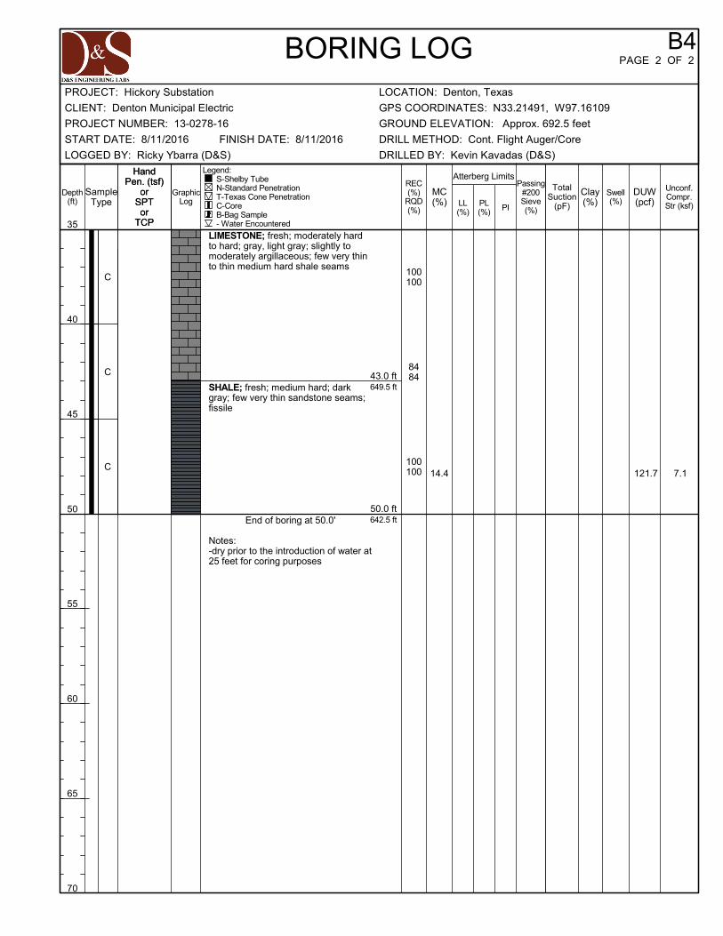
649.5 ft
642.5 ft
121.7 7.114.4
43.0 ft
50.0 ft
LIMESTONE; fresh; moderately hardto hard; gray, light gray; slightly tomoderately argillaceous; few very thinto thin medium hard shale seams
SHALE; fresh; medium hard; darkgray; few very thin sandstone seams;fissile
End of boring at 50.0'
Notes:-dry prior to the introduction of water at25 feet for coring purposes
100100
8484
100100
C
C
C
Swell(%)LL
(%)PL(%) PI
TotalSuction
(pF)
HandPen. (tsf)
orSPTor
TCP
HandPen. (tsf)
orSPTor
TCP
Passing#200Sieve(%)
BORING LOG
GraphicLog
DUW(pcf)
Unconf.Compr.Str (ksf)
Depth(ft)
35
40
45
50
55
60
65
70
Atterberg Limits
Clay(%)
B4PAGE 2 OF 2
MC(%)
Legend: S-Shelby Tube N-Standard Penetration T-Texas Cone Penetration C-Core B-Bag Sample - Water Encountered
REC(%)
RQD(%)
SampleType
CLIENT: Denton Municipal Electric
LOCATION: Denton, TexasPROJECT: Hickory Substation
DRILLED BY: Kevin Kavadas (D&S)
START DATE: 8/11/2016 DRILL METHOD: Cont. Flight Auger/Core
LOGGED BY: Ricky Ybarra (D&S)
FINISH DATE: 8/11/2016
GROUND ELEVATION: Approx. 692.5 feet
GPS COORDINATES: N33.21491, W97.16109
PROJECT NUMBER: 13-0278-16

1.5
44
45
16
18
28
27
9,10
6,7
4.5+
4.5+
4.5+
4.5+
4.5+
4.5+
4.5+
4.5+
4.5+
4.5+
693.0 ft
686.5 ft
669.7 ft
668.2 ft
108.0
111.2
105.3
111.3
135.7
9.2
0.7
14.1
54.4
8.9
15.1
14.1
14.5
14.8
20.2
17.6
23.5
19.0
20.0
19.7
9.1
2.0 ft
8.5 ft
25.3 ft
26.8 ft
FILL: CLAYEY SAND (SC); mediumdense; brown, reddish brown; traceaggregate and debris fragments
LEAN CLAY (CL); very stiff; brown,dark brown; trace calcareous andferrous nodules
SHALE; highly weathered; very soft;brown, light gray; fissile
SHALE; slightly to moderatelyweathered; soft; brown, gray; fissile
LIMESTONE; fresh; moderately hardto hard; gray, light gray; slightly tomoderately argillaceous; few very thinto thin medium hard shale seams
100100
100100
S
S
S
T
S
S
S
T
S
S
S
S
S
C
C
Swell(%)LL
(%)PL(%) PI
TotalSuction
(pF)
HandPen. (tsf)
orSPTor
TCP
HandPen. (tsf)
orSPTor
TCP
Passing#200Sieve(%)
BORING LOG
GraphicLog
DUW(pcf)
Unconf.Compr.Str (ksf)
Depth(ft)
0
5
10
15
20
25
30
35
Atterberg Limits
Clay(%)
B5PAGE 1 OF 2
MC(%)
Legend: S-Shelby Tube N-Standard Penetration T-Texas Cone Penetration C-Core B-Bag Sample - Water Encountered
REC(%)
RQD(%)
SampleType
CLIENT: Denton Municipal Electric
LOCATION: Denton, TexasPROJECT: Hickory Substation
DRILLED BY: Kevin Kavadas (D&S)
START DATE: 8/10/2016 DRILL METHOD: Cont. Flight Auger/Core
LOGGED BY: Ricky Ybarra (D&S)
FINISH DATE: 8/10/2016
GROUND ELEVATION: Approx. 695.0 feet
GPS COORDINATES: N33.21571, W97.16111
PROJECT NUMBER: 13-0278-16

648.9 ft
645.0 ft
119.5 18.714.3
46.1 ft
50.0 ft
LIMESTONE; fresh; moderately hardto hard; gray, light gray; slightly tomoderately argillaceous; few very thinto thin medium hard shale seams
SHALE; fresh; medium hard; darkgray; few very thin sandstone seams;fissile
End of boring at 50.0'
Notes:-dry prior to the introduction of water at25 feet for coring purposes
100100
100100
100100
C
C
C
Swell(%)LL
(%)PL(%) PI
TotalSuction
(pF)
HandPen. (tsf)
orSPTor
TCP
HandPen. (tsf)
orSPTor
TCP
Passing#200Sieve(%)
BORING LOG
GraphicLog
DUW(pcf)
Unconf.Compr.Str (ksf)
Depth(ft)
35
40
45
50
55
60
65
70
Atterberg Limits
Clay(%)
B5PAGE 2 OF 2
MC(%)
Legend: S-Shelby Tube N-Standard Penetration T-Texas Cone Penetration C-Core B-Bag Sample - Water Encountered
REC(%)
RQD(%)
SampleType
CLIENT: Denton Municipal Electric
LOCATION: Denton, TexasPROJECT: Hickory Substation
DRILLED BY: Kevin Kavadas (D&S)
START DATE: 8/10/2016 DRILL METHOD: Cont. Flight Auger/Core
LOGGED BY: Ricky Ybarra (D&S)
FINISH DATE: 8/10/2016
GROUND ELEVATION: Approx. 695.0 feet
GPS COORDINATES: N33.21571, W97.16111
PROJECT NUMBER: 13-0278-16

0.927
42
13
16
14
26
4,4
4,5
5,7
4.5+
4.5+
4.5+
3.5
3.25
4.5+
4.5+
4.5+
4.5+
695.5 ft
689.0 ft
675.5 ft
669.0 ft
110.7
104.1
117.8
114.8
5.3
11.7
26.8
10.0
12.0
18.5
21.6
19.4
15.1
13.8
17.7
17.0
2.0 ft
8.5 ft
22.0 ft
28.5 ft
FILL: CLAYEY SAND (SC); mediumdense; brown, reddish brown, darkbrown; with aggregate fragments
LEAN CLAY (CL); very stiff; brown,red brown; few ferrous nodules andsand; trace calcareous nodules
SHALE; highly weathered; very soft;brown, light gray; fissile
LIMESTONE; slightly to moderatelyweathered; medium to moderatelyhard; brown, light gray
LIMESTONE; fresh; moderately hardto hard; gray, light gray; slightly tomoderately argillaceous; few very thinto thin medium hard shale seams
100100
100100
S
S
S
T
S
T
S
T
S
S
S
S
C
C
Swell(%)LL
(%)PL(%) PI
TotalSuction
(pF)
HandPen. (tsf)
orSPTor
TCP
HandPen. (tsf)
orSPTor
TCP
Passing#200Sieve(%)
BORING LOG
GraphicLog
DUW(pcf)
Unconf.Compr.Str (ksf)
Depth(ft)
0
5
10
15
20
25
30
35
Atterberg Limits
Clay(%)
B6PAGE 1 OF 2
MC(%)
Legend: S-Shelby Tube N-Standard Penetration T-Texas Cone Penetration C-Core B-Bag Sample - Water Encountered
REC(%)
RQD(%)
SampleType
CLIENT: Denton Municipal Electric
LOCATION: Denton, TexasPROJECT: Hickory Substation
DRILLED BY: Kevin Kavadas (D&S)
START DATE: 8/9/2016 DRILL METHOD: Cont. Flight Auger/Core
LOGGED BY: Ricky Ybarra (D&S)
FINISH DATE: 8/9/2016
GROUND ELEVATION: Approx. 697.5 feet
GPS COORDINATES: N33.21565, W97.16044
PROJECT NUMBER: 13-0278-16

649.5 ft
647.5 ft
139.0
145.4
79.0
160.1
7.6
5.8
48.0 ft
50.0 ft
LIMESTONE; fresh; moderately hardto hard; gray, light gray; slightly tomoderately argillaceous; few very thinto thin medium hard shale seams
SHALE; fresh; medium hard; darkgray; few very thin sandstone seams;fissile
End of boring at 50.0'
Notes:-dry prior to the introduction of water at25 feet for coring purposes
100100
100100
100100
C
C
C
Swell(%)LL
(%)PL(%) PI
TotalSuction
(pF)
HandPen. (tsf)
orSPTor
TCP
HandPen. (tsf)
orSPTor
TCP
Passing#200Sieve(%)
BORING LOG
GraphicLog
DUW(pcf)
Unconf.Compr.Str (ksf)
Depth(ft)
35
40
45
50
55
60
65
70
Atterberg Limits
Clay(%)
B6PAGE 2 OF 2
MC(%)
Legend: S-Shelby Tube N-Standard Penetration T-Texas Cone Penetration C-Core B-Bag Sample - Water Encountered
REC(%)
RQD(%)
SampleType
CLIENT: Denton Municipal Electric
LOCATION: Denton, TexasPROJECT: Hickory Substation
DRILLED BY: Kevin Kavadas (D&S)
START DATE: 8/9/2016 DRILL METHOD: Cont. Flight Auger/Core
LOGGED BY: Ricky Ybarra (D&S)
FINISH DATE: 8/9/2016
GROUND ELEVATION: Approx. 697.5 feet
GPS COORDINATES: N33.21565, W97.16044
PROJECT NUMBER: 13-0278-16

0.923 13 10
13,12
5,6
9,13
4.5+
4.5+
4.5+
4.25
4.0
4.5+
4.5+
4.5+
4.5+
4.5+
4.5+
48
689.0 ft
684.0 ft
666.5 ft
661.5 ft
113.3
109.3
124.7
109.6
12.0
10.3
10.6
7.3
9.5
9.6
18.2
17.0
12.6
11.7
19.9
3.0 ft
8.0 ft
25.5 ft
30.5 ft
FILL: CLAYEY SAND (SC); mediumdense; reddish brown, brown, darkbrown; trace gravel
LEAN CLAY (CL); very stiff; brown;few calcareous nodules; trace ferrousnodules and sand
SHALE; highly weathered; very soft;brown, light gray; fissile
LIMESTONE; slightly to moderatelyweathered; medium to moderatelyhard; brown, light gray
LIMESTONE; fresh; moderately hardto hard; gray, light gray; slightly tomoderately argillaceous; few very thinto thin medium hard shale seams 100
100
S
S
S
T
S
T
S
T
S
S
S
S
S
S
C
Swell(%)LL
(%)PL(%) PI
TotalSuction
(pF)
HandPen. (tsf)
orSPTor
TCP
HandPen. (tsf)
orSPTor
TCP
Passing#200Sieve(%)
BORING LOG
GraphicLog
DUW(pcf)
Unconf.Compr.Str (ksf)
Depth(ft)
0
5
10
15
20
25
30
35
Atterberg Limits
Clay(%)
B7PAGE 1 OF 2
MC(%)
Legend: S-Shelby Tube N-Standard Penetration T-Texas Cone Penetration C-Core B-Bag Sample - Water Encountered
REC(%)
RQD(%)
SampleType
CLIENT: Denton Municipal Electric
LOCATION: Denton, TexasPROJECT: Hickory Substation
DRILLED BY: Kevin Kavadas (D&S)
START DATE: 8/8/2016 DRILL METHOD: Cont. Flight Auger/Core
LOGGED BY: Ricky Ybarra (D&S)
FINISH DATE: 8/8/2016
GROUND ELEVATION: Approx. 692.0 feet
GPS COORDINATES: N33.21500, W97.16067
PROJECT NUMBER: 13-0278-16

646.8 ft
642.0 ft
140.4
146.3
42.1
190.9
6.9
5.8
45.2 ft
50.0 ft
LIMESTONE; fresh; moderately hardto hard; gray, light gray; slightly tomoderately argillaceous; few very thinto thin medium hard shale seams
SHALE; fresh; medium hard; darkgray; few very thin sandstone seams;fissile
End of boring at 50.0'
Notes:-dry prior to the introduction of water at30.5 feet for coring purposes
100100
100100
4040
C
C
C
Swell(%)LL
(%)PL(%) PI
TotalSuction
(pF)
HandPen. (tsf)
orSPTor
TCP
HandPen. (tsf)
orSPTor
TCP
Passing#200Sieve(%)
BORING LOG
GraphicLog
DUW(pcf)
Unconf.Compr.Str (ksf)
Depth(ft)
35
40
45
50
55
60
65
70
Atterberg Limits
Clay(%)
B7PAGE 2 OF 2
MC(%)
Legend: S-Shelby Tube N-Standard Penetration T-Texas Cone Penetration C-Core B-Bag Sample - Water Encountered
REC(%)
RQD(%)
SampleType
CLIENT: Denton Municipal Electric
LOCATION: Denton, TexasPROJECT: Hickory Substation
DRILLED BY: Kevin Kavadas (D&S)
START DATE: 8/8/2016 DRILL METHOD: Cont. Flight Auger/Core
LOGGED BY: Ricky Ybarra (D&S)
FINISH DATE: 8/8/2016
GROUND ELEVATION: Approx. 692.0 feet
GPS COORDINATES: N33.21500, W97.16067
PROJECT NUMBER: 13-0278-16

9.835
44
20
11
15
33
3,7
11,11
8,9
4.5+
4.5+
4.5+
4.5+
4.5+
4.5+
4.5+
4.5+
4.5+
689.8 ft
680.8 ft
669.8 ft
664.8 ft
123.9
100.3
128.5
146.6
136.9
9.3
62.1
168.7
42.9
11.6
11.6
11.0
15.4
18.2
17.8
15.7
11.3
5.1
7.7
2.0 ft
11.0 ft
22.0 ft
27.0 ft
FILL: CLAYEY SAND (SC); mediumdense; dark brown, brown, reddishbrown; few aggregate fragments
LEAN CLAY (CL); very stiff; darkbrown, reddish brown mottling, brown;with sand; few ferrous nodules; tracecalcareous nodules
SHALE; highly weathered; very soft;brown, light gray; fissile
LIMESTONE; slightly to moderatelyweathered; medium to moderatelyhard; brown, light gray
LIMESTONE; fresh; moderately hardto hard; gray, light gray; slightly tomoderately argillaceous; few very thinto thin medium hard shale seams
100100
100100
S
S
S
T
S
T
S
T
S
S
S
S
C
C
Swell(%)LL
(%)PL(%) PI
TotalSuction
(pF)
HandPen. (tsf)
orSPTor
TCP
HandPen. (tsf)
orSPTor
TCP
Passing#200Sieve(%)
BORING LOG
GraphicLog
DUW(pcf)
Unconf.Compr.Str (ksf)
Depth(ft)
0
5
10
15
20
25
30
35
Atterberg Limits
Clay(%)
B8PAGE 1 OF 2
MC(%)
Legend: S-Shelby Tube N-Standard Penetration T-Texas Cone Penetration C-Core B-Bag Sample - Water Encountered
REC(%)
RQD(%)
SampleType
CLIENT: Denton Municipal Electric
LOCATION: Denton, TexasPROJECT: Hickory Substation
DRILLED BY: Kevin Kavadas (D&S)
START DATE: 8/11/2016 DRILL METHOD: Cont. Flight Auger/Core
LOGGED BY: Ricky Ybarra (D&S)
FINISH DATE: 8/11/2016
GROUND ELEVATION: Approx. 691.8 feet
GPS COORDINATES: N33.21500, W97.16099
PROJECT NUMBER: 13-0278-16

647.8 ft
641.8 ft
121.7 21.813.8
44.0 ft
50.0 ft
LIMESTONE; fresh; moderately hardto hard; gray, light gray; slightly tomoderately argillaceous; few very thinto thin medium hard shale seams
SHALE; fresh; medium hard; darkgray; few very thin sandstone seams;fissile
End of boring at 50.0'
Notes:-dry prior to the introduction of water at25 feet for coring purposes
100100
8686
100100
C
C
C
Swell(%)LL
(%)PL(%) PI
TotalSuction
(pF)
HandPen. (tsf)
orSPTor
TCP
HandPen. (tsf)
orSPTor
TCP
Passing#200Sieve(%)
BORING LOG
GraphicLog
DUW(pcf)
Unconf.Compr.Str (ksf)
Depth(ft)
35
40
45
50
55
60
65
70
Atterberg Limits
Clay(%)
B8PAGE 2 OF 2
MC(%)
Legend: S-Shelby Tube N-Standard Penetration T-Texas Cone Penetration C-Core B-Bag Sample - Water Encountered
REC(%)
RQD(%)
SampleType
CLIENT: Denton Municipal Electric
LOCATION: Denton, TexasPROJECT: Hickory Substation
DRILLED BY: Kevin Kavadas (D&S)
START DATE: 8/11/2016 DRILL METHOD: Cont. Flight Auger/Core
LOGGED BY: Ricky Ybarra (D&S)
FINISH DATE: 8/11/2016
GROUND ELEVATION: Approx. 691.8 feet
GPS COORDINATES: N33.21500, W97.16099
PROJECT NUMBER: 13-0278-16

2.741 19 22
5,6
4,4
5,5
4.5+
4.0
4.0
4.0
4.0
3.5
4.25
4.5+
4.5+
64 692.2 ft
683.2 ft
672.2 ft
668.2 ft
109.4
109.0
109.1
117.3
139.3
3.9
8.9
26.4
55.6
12.9
11.5
17.4
19.2
19.8
19.3
18.9
20.4
16.3
7.8
2.0 ft
11.0 ft
22.0 ft
26.0 ft
FILL: CLAYEY SAND (SC); mediumdense; brown, dark brown, reddishbrown; trace aggregate fragments
LEAN CLAY (CL); very stiff; darkbrown, brown, reddish brown; withsand; few calcareous nodules
SHALE; highly weathered; very soft;brown, light gray; fissile
LIMESTONE; slightly to moderatelyweathered; medium to moderatelyhard; brown, light gray
LIMESTONE; fresh; moderately hardto hard; gray, light gray; slightly tomoderately argillaceous; few very thinto thin medium hard shale seams
8888
100100
S
S
S
T
S
T
S
T
S
S
S
S
C
C
Swell(%)LL
(%)PL(%) PI
TotalSuction
(pF)
HandPen. (tsf)
orSPTor
TCP
HandPen. (tsf)
orSPTor
TCP
Passing#200Sieve(%)
BORING LOG
GraphicLog
DUW(pcf)
Unconf.Compr.Str (ksf)
Depth(ft)
0
5
10
15
20
25
30
35
Atterberg Limits
Clay(%)
B9PAGE 1 OF 2
MC(%)
Legend: S-Shelby Tube N-Standard Penetration T-Texas Cone Penetration C-Core B-Bag Sample - Water Encountered
REC(%)
RQD(%)
SampleType
CLIENT: Denton Municipal Electric
LOCATION: Denton, TexasPROJECT: Hickory Substation
DRILLED BY: Kevin Kavadas (D&S)
START DATE: 8/10/2016 DRILL METHOD: Cont. Flight Auger/Core
LOGGED BY: Ricky Ybarra (D&S)
FINISH DATE: 8/10/2016
GROUND ELEVATION: Approx. 694.2 feet
GPS COORDINATES: N33.21550, W97.16096
PROJECT NUMBER: 13-0278-16

649.4 ft
644.2 ft
142.0 145.86.4
44.8 ft
50.0 ft
LIMESTONE; fresh; moderately hardto hard; gray, light gray; slightly tomoderately argillaceous; few very thinto thin medium hard shale seams
SHALE; fresh; medium hard; darkgray; few very thin sandstone seams;fissile
End of boring at 50.0'
Notes:-dry prior to the introduction of water at25 feet for coring purposes
100100
9494
9898
C
C
C
Swell(%)LL
(%)PL(%) PI
TotalSuction
(pF)
HandPen. (tsf)
orSPTor
TCP
HandPen. (tsf)
orSPTor
TCP
Passing#200Sieve(%)
BORING LOG
GraphicLog
DUW(pcf)
Unconf.Compr.Str (ksf)
Depth(ft)
35
40
45
50
55
60
65
70
Atterberg Limits
Clay(%)
B9PAGE 2 OF 2
MC(%)
Legend: S-Shelby Tube N-Standard Penetration T-Texas Cone Penetration C-Core B-Bag Sample - Water Encountered
REC(%)
RQD(%)
SampleType
CLIENT: Denton Municipal Electric
LOCATION: Denton, TexasPROJECT: Hickory Substation
DRILLED BY: Kevin Kavadas (D&S)
START DATE: 8/10/2016 DRILL METHOD: Cont. Flight Auger/Core
LOGGED BY: Ricky Ybarra (D&S)
FINISH DATE: 8/10/2016
GROUND ELEVATION: Approx. 694.2 feet
GPS COORDINATES: N33.21550, W97.16096
PROJECT NUMBER: 13-0278-16

1.5
30
26
13
13
17
13
12,19
6,8
6,6
4.5+
4.5+
4.5+
4.0
4.5+
4.5+
4.5+
4.5+
693.2 ft
684.2 ft
673.2 ft
667.2 ft
111.8
116.7
77.8
108.7
1.7
1.0
12.8
10.1
6.5
11.6
16.1
16.9
15.8
21.2
18.8
2.0 ft
11.0 ft
22.0 ft
28.0 ft
FILL: CLAYEY SAND (SC); mediumdense; dark brown, reddish brown;with aggregate fragments and gravel
LEAN CLAY (CL); very stiff; darkbrown; with sand
SHALE; highly weathered; very soft;brown, light gray; fissile
LIMESTONE; slightly to moderatelyweathered; medium to moderatelyhard; brown, light gray
LIMESTONE; fresh; moderately hardto hard; gray, light gray; slightly tomoderately argillaceous; few very thinto thin medium hard shale seams
100100
100100
S
S
S
T
NR
T
S
T
S
S
S
S
C
C
Swell(%)LL
(%)PL(%) PI
TotalSuction
(pF)
HandPen. (tsf)
orSPTor
TCP
HandPen. (tsf)
orSPTor
TCP
Passing#200Sieve(%)
BORING LOG
GraphicLog
DUW(pcf)
Unconf.Compr.Str (ksf)
Depth(ft)
0
5
10
15
20
25
30
35
Atterberg Limits
Clay(%)
B10PAGE 1 OF 2
MC(%)
Legend: S-Shelby Tube N-Standard Penetration T-Texas Cone Penetration C-Core B-Bag Sample - Water Encountered
REC(%)
RQD(%)
SampleType
CLIENT: Denton Municipal Electric
LOCATION: Denton, TexasPROJECT: Hickory Substation
DRILLED BY: Kevin Kavadas (D&S)
START DATE: 8/9/2016 DRILL METHOD: Cont. Flight Auger/Core
LOGGED BY: Ricky Ybarra (D&S)
FINISH DATE: 8/9/2016
GROUND ELEVATION: Approx. 695.2 feet
GPS COORDINATES: N33.21554, W97.16060
PROJECT NUMBER: 13-0278-16

647.7 ft
645.2 ft
137.6
129.9
30.1
109.3
8.1
7.1 47.5 ft
50.0 ft
LIMESTONE; fresh; moderately hardto hard; gray, light gray; slightly tomoderately argillaceous; few very thinto thin medium hard shale seams
SHALE; fresh; medium hard; darkgray; few very thin sandstone seams;fissile
End of boring at 50.0'
Notes:-dry prior to the introduction of water at25 feet for coring purposes
100100
100100
100100
C
C
C
Swell(%)LL
(%)PL(%) PI
TotalSuction
(pF)
HandPen. (tsf)
orSPTor
TCP
HandPen. (tsf)
orSPTor
TCP
Passing#200Sieve(%)
BORING LOG
GraphicLog
DUW(pcf)
Unconf.Compr.Str (ksf)
Depth(ft)
35
40
45
50
55
60
65
70
Atterberg Limits
Clay(%)
B10PAGE 2 OF 2
MC(%)
Legend: S-Shelby Tube N-Standard Penetration T-Texas Cone Penetration C-Core B-Bag Sample - Water Encountered
REC(%)
RQD(%)
SampleType
CLIENT: Denton Municipal Electric
LOCATION: Denton, TexasPROJECT: Hickory Substation
DRILLED BY: Kevin Kavadas (D&S)
START DATE: 8/9/2016 DRILL METHOD: Cont. Flight Auger/Core
LOGGED BY: Ricky Ybarra (D&S)
FINISH DATE: 8/9/2016
GROUND ELEVATION: Approx. 695.2 feet
GPS COORDINATES: N33.21554, W97.16060
PROJECT NUMBER: 13-0278-16

1.531 13 18
14,19
10,12
12,12
4.5+
4.5+
4.5+
4.5+
4.5+
4.5+
4.5+
4.5+
2.5
4.5+
691.0 ft
682.0 ft
666.0 ft
111.3
107.7
113.0
116.9
143.3
9.0
3.0
19.1
142.2
7.8
10.5
8.4
13.4
16.7
15.1
15.8
19.7
16.5
6.3
2.0 ft
11.0 ft
27.0 ft
FILL: CLAYEY SAND (SC); mediumdense; brown, reddish brown, darkbrown; trace aggregate fragments
LEAN CLAY (CL); very stiff; darkbrown, reddish brown, light gray; withsand; few ferrous nodules; tracecalcareous nodules
SHALE; highly weathered; very soft;brown, light gray; fissile
LIMESTONE; fresh; moderately hardto hard; gray, light gray; slightly tomoderately argillaceous; few very thinto thin medium hard shale seams
100100
S
S
S
T
S
T
S
T
S
S
S
S
S
C
Swell(%)LL
(%)PL(%) PI
TotalSuction
(pF)
HandPen. (tsf)
orSPTor
TCP
HandPen. (tsf)
orSPTor
TCP
Passing#200Sieve(%)
BORING LOG
GraphicLog
DUW(pcf)
Unconf.Compr.Str (ksf)
Depth(ft)
0
5
10
15
20
25
30
35
Atterberg Limits
Clay(%)
B11PAGE 1 OF 2
MC(%)
Legend: S-Shelby Tube N-Standard Penetration T-Texas Cone Penetration C-Core B-Bag Sample - Water Encountered
REC(%)
RQD(%)
SampleType
CLIENT: Denton Municipal Electric
LOCATION: Denton, TexasPROJECT: Hickory Substation
DRILLED BY: Kevin Kavadas (D&S)
START DATE: 8/8/2016 DRILL METHOD: Cont. Flight Auger/Core
LOGGED BY: Ricky Ybarra (D&S)
FINISH DATE: 8/8/2016
GROUND ELEVATION: Approx. 693.0 feet
GPS COORDINATES: N33.21525, W97.16077
PROJECT NUMBER: 13-0278-16

648.2 ft
643.0 ft
146.7 332.45.3
44.8 ft
50.0 ft
LIMESTONE; fresh; moderately hardto hard; gray, light gray; slightly tomoderately argillaceous; few very thinto thin medium hard shale seams
SHALE; fresh; medium hard; darkgray; few very thin sandstone seams;fissile
End of boring at 50.0'
Notes:-dry prior to the introduction of water at30 feet for coring purposes
9090
100100
8080
C
C
C
Swell(%)LL
(%)PL(%) PI
TotalSuction
(pF)
HandPen. (tsf)
orSPTor
TCP
HandPen. (tsf)
orSPTor
TCP
Passing#200Sieve(%)
BORING LOG
GraphicLog
DUW(pcf)
Unconf.Compr.Str (ksf)
Depth(ft)
35
40
45
50
55
60
65
70
Atterberg Limits
Clay(%)
B11PAGE 2 OF 2
MC(%)
Legend: S-Shelby Tube N-Standard Penetration T-Texas Cone Penetration C-Core B-Bag Sample - Water Encountered
REC(%)
RQD(%)
SampleType
CLIENT: Denton Municipal Electric
LOCATION: Denton, TexasPROJECT: Hickory Substation
DRILLED BY: Kevin Kavadas (D&S)
START DATE: 8/8/2016 DRILL METHOD: Cont. Flight Auger/Core
LOGGED BY: Ricky Ybarra (D&S)
FINISH DATE: 8/8/2016
GROUND ELEVATION: Approx. 693.0 feet
GPS COORDINATES: N33.21525, W97.16077
PROJECT NUMBER: 13-0278-16

B1 2-3 12.4 16.3 391 4.6
B2 4-5 17.6 25.7 651 9.6
B3 2-3 16.4 22.8 395 6.3
B4 2-3 18.4 26.6 395 6.7
B5 6-7 20.2 21.0 910 1.5
B6 1-2 12.0 14.1 263 0.9
B7 2-3 9.6 20.3 390 0.9
B8 1-2 11.6 19.5 263 9.8
B9 2-3 17.4 20.0 392 2.7
B10 2-3 11.6 19.9 391 1.5
B11 4-5 13.4 19.1 651 1.5
BoringNumber
Depthfeet
Applied Pressure,psf
Vertical Swell, %
SWELL TEST RESULTS
Final MoistureContent, %
Initial MoistureContent, %
CLIENT: Denton Municipal ElectricPROJECT: Hickory Substation
PROJECT NUMBER: 13-0278-16 LOCATION: Denton, Texas

APPENDIX B - THERMAL RESISTIVITY TEST RESULTS

COOL SOLUTIONS FOR UNDERGROUND POWER CABL
THERMAL SURVEYS, CORRECTIVE BACKFILLS & INSTRUMENTATION
Serving the electric power industry since 1978
4370 Contractors Common
Livermore, CA 94551
Tel: 925-999-9232
Fax: 925-999-8837
http://www.geothermusa.com
August 25, 2016
Power Engineers Inc.
16011 College Blvd, Suite 130
Lenexa, KS 66219
Attn: Dennis Johnson
Re: Thermal Analysis of Native Soil Samples
DME Hickory Substation - Denton, TX (Project No. 13-0278-16)
The following is the report of thermal dryout characterization tests conducted on fifteen (15) undisturbed tube samples of native soil from the referenced project received at our laboratory.
Thermal Resistivity Tests: For thermal dryout characterization the undisturbed tube samples were tested ‘as received’. A series of thermal resistivity measurements were made in stages, with moisture contents ranging from the ‘as received’ to totally dry condition. The tests were conducted in accordance with the IEEE Standard 442. The results are tabulated below and the thermal dryout curves are presented in Figures 1 - 3.
Sample ID, Description, Thermal Resistivity, Moisture Content and Density
Sample ID Description
(D&S Eng)
Thermal Resistivity
(°C-cm/W) Moisture
Content
(%)
Dry
Density
(lb/ft3) As-rcvd Dry
B1 @ 5' - 6' Lean Clay (CL) 58 125 13 121
B1 @ 10' - 11' Highly weathered limestone 57 127 21 105
B1 @ 15' - 16' Highly weathered limestone 56 130 20 107
B2 @ 5' - 6' Lean Clay (CL) 72 158 16 107
B2 @ 10' - 11' Highly weathered limestone 57 128 20 106
B2 @ 15' - 16' Highly weathered limestone 53 127 18 107

2
Sample ID, Description, Thermal Resistivity, Moisture Content and Density
Sample ID Description
(D&S Eng)
Thermal Resistivity
(°C-cm/W) Moisture
Content
(%)
Dry
Density
(lb/ft3) As-rcvd Dry
B3 @ 5' - 6' Lean Clay (CL) 70 157 17 107
B3 @ 10' - 11' Highly weathered limestone 57 130 21 104
B3 @ 15' - 16' Highly weathered limestone 54 128 18 107
B5 @ 5' - 6' Lean Clay (CL) 75 162 19 99
B5 @ 10' - 11' Highly weathered limestone 53 125 19 108
B5 @ 15' - 16' Highly weathered limestone 55 129 20 106
B11 @ 5' - 6' Lean Clay (CL) 62 130 14 113
B11 @ 10' - 11' Lean Clay (CL) 56 122 12 122
B11 @ 15' - 16' Highly weathered limestone 55 127 19 107
Comments: The thermal characteristic depicted in the dryout curves apply for the soils at their respective test dry density. Please contact us if you have any questions or if we can be of further assistance.
Geotherm USA Deepak Parmar Please Note: All samples will be disposed of after 5 days from date of report.

3

4

5

APPENDIX C - GENERAL DESCRIPTION OF PROCEDURES

ANALYTICAL METHODS TO PREDICT MOVEMENT
CLASSIFICATION TESTS
Classification testing is perhaps the most basic, yet fundamental tool available for predicting potential movements of clay soils. Classification testing typically consists of moisture content, Atterberg Limits, and Grain-size distribution determinations. From these results a general assessment of a soil’s propensity for volume change with changes in soil moisture content can be made.
Moisture Content
By studying the moisture content of the soils at varying depths and comparing them with the results of Atterberg Limits, one can estimate a rough order of magnitude of potential soil movement at various moisture contents, as well as movements with moisture changes. These tests are typically performed in accordance with ASTM D 2216.
Atterberg Limits
Atterberg limits determine the liquid limit (LL), plastic limit (PL), and plasticity index (PI) of a soil. The liquid limit is the moisture content at which a soil begins to behave as a viscous fluid. The plastic limit is the moisture content at which a soil becomes workable like putty, and at which a clay soil begins to crumble when rolled into a thin thread (1/8” diameter). The PI is the numerical difference between the moisture constants at the liquid limit and the plastic limit. This test is typically performed in accordance with ASTM D 4318.
Clay mineralogy and the particle size influence the Atterberg Limits values, with certain minerals (e.g., montmorillonite) and smaller particle sizes having higher PI values, and therefore higher movement potential.
A soil with a PI below about 15 to 18 is considered to be generally stable and should not experience significant movement with changes in moisture content. Soils with a PI above about 30 to 35 are considered to be highly active and may exhibit considerable movement with changes in moisture content.
Fat clays with very high liquid limits, weakly cemented sandy clays, or silty clays are examples of soils in which it can be difficult to predict movement from classification testing alone.
Grain-size Distribution
The simplest grain-size distribution test involves washing a soil specimen over the No. 200 mesh sieve with an opening size of 0.075 mm (ASTM D 1140)). This particle size has been defined by the engineering community as the demarcation between coarse-grained and fine-grained soils. Particles smaller than this size can be further distinguished between silt-size and clay-size particles by use of a Hydrometer test (ASTM D 422). A more complete grain-size distribution test that uses sieves to relative amount of particles according is the Sieve Gradation Analysis of Soils (ASTM D 6913). Once the characteristics of the soil are determined through classification testing, a number of movement prediction techniques are available to predict the potential movement of the soils. Some of these are discussed in general below.

TEXAS DEPARTMENT OF TRANSPORTATION METHOD 124-E
The Texas Department of Transportation (TxDOT) has developed a generally simplistic method to predict movements for highways based on the plasticity index of the soil. The TxDOT method is empirical and is based on the Atterberg limits and moisture content of the subsurface soil. This method generally assumes three different initial moisture conditions: dry, “as-is”, and wet. Computation of each over an assumed depth of seasonal moisture variation (usually about 15 feet or less) provides an estimate of potential movement at each initial condition. This method requires a number of additional assumptions to develop a potential movement estimate. As such, the predicted movements generally possess large uncertainties when applied to the analysis of conditions under building slabs and foundations. In our opinion, estimates derived by this method should not be used alone in determination of potential movement.
SUCTION
Suction measurements may be used along with other movement prediction methods to predict soil movement. Suction is a measure of the ability of a soil to attract or lose moisture between the soil particles. Since changes in soil moisture result in volume changes within the soil mass of fine-grained soils (clays and to some degree silts), a knowledge of the suction potential of a soil mass at a given point in time may be used to estimate potential future volume changes with changes in soil moisture content. For this analysis, a series of suction measurements versus depth is typically performed on a number of soil samples recovered from a boring in order to develop a suction profile.
SWELL TESTS
Swell tests can lead to more accurate site specific predictions of potential vertical movement by measuring actual swell volumes at in situ initial moisture contents. One-dimensional swell tests are almost always performed for this measurement. Though swell is a three-dimensional process, the one-dimensional test provides greatly improved potential vertical movement estimates than other methods alone, particularly when the results are “weighted” with respect to depth, putting more emphasis on the swell characteristics closer to the surface and less on values at depth.

POTENTIAL VERTICAL MOVEMENT
A general index for movement is known as the Potential Vertical Rise (PVR). The actual term PVR refers to the TxDOT Method 124-E mentioned above. For the purpose of this report the term Potential Vertical Movement (PVM) will be used since PVM estimates are derived using multiple analytical techniques, not just TxDOT methods. It should be noted that slabs and foundations constructed on clay or clayey soils may have at least some risk of potential vertical movement due to changes in soil moisture contents. To eliminate that risk, slabs and foundation elements may be designed as structural elements physically separated by some distance from the subgrade soils (usually 4 to 12 inches).
In some cases, a floor slab with movements as little as 1/4 of an inch may result in damage to interior walls, such as cracking in sheet rock or masonry walls, or separation of floor tiles. However, these cracks are often minor and most people consider them 'liveable'. In other cases, movement of one inch may cause significant damage, inconvenience, or even create a hazard (trip hazard or others). Vertical movement of clay soils under slab on grade foundations due to soil moisture changes can result from a variety causes, including poor site grading and drainage, improperly prepared subgrade, trees and large shrubbery located too close to structures, utility leaks or breaks, poor subgrade maintenance such as inadequate or excessive irrigation, or other causes. The potential for post-construction vertical movement can be minimized through adequate design, proper construction, and adherence to the recommendations contained herein for post-construction maintenance. POTENTIAL VERTICAL MOVEMENT (PVM)
PVM is generally considered to be a measurement of the change in height of a foundation from the elevation it was originally placed. Experience and generally accepted practice suggests that if the PVM of a site is less than one inch, the associated differential movement will be minor and acceptable to most people.

SETTLEMENT
Settlement is a measure of a downward movement due to consolidation of soil. This can occur from improperly placed fill (uncompacted or under-compacted), loose native soil, or from large amounts of unconfined sandy material. Properly compacted fill may settle approximately 1 percent of its depth, particularly when fill depths exceed 10 feet.
EDGE AND CENTER LIFT MOVEMENT (ym)
The Post-Tensioning Institute (PTI) has developed a parameter of movement defined as the differential movement (ym) estimated using the change in soil surface elevation in two locations separated by a distance em within which the differential movement will occur; em being measured from the exterior of a building to some distance toward the interior. All calculations for this report are based on the modified PTI procedure in addition to our judgment as necessary for specific site conditions. The minimum movements given in the PTI are for climatic conditions only and have been modified somewhat to account for site conditions which may increase the actual parameters.
“Center lift” occurs when the center, or some portion of the center of the building, is higher than the exterior. This can occur when the soil around the exterior shrinks, or the soil under the center of the building swells, or a combination of both occurs.
“Edge lift” occurs when the edge, or some portion of the exterior of the building, is higher than the center. This can occur when the soil around the exterior swells. It is not uncommon to have both the center lift and the edge lift phenomena occurring on the same building, in different areas.

SPECIAL COMMENTARY ON CONCRETE AND EARTHWORK
RESTRAINT TO SHRINKAGE CRACKS
One of the characteristics of concrete is that during the curing process shrinkage occurs and if there are any restraints to prevent the concrete from shrinking, cracks can form. In a typical slab on grade or structurally suspended foundation there will be cracks due to interior beams and piers that restrict shrinkage. This restriction is called Restraint to Shrinkage (RTS). In post tensioned slabs, the post tensioning strands are slack when installed and must be stressed at a later time. The best procedure is to stress the cables approximately 30 percent within one to two days of placing the concrete. Then the cables are stressed fully when the concrete reaches greater strength, usually in 7 days. During this time before the cables are stressed fully, the concrete may crack more than conventionally reinforced slabs. When the cables are stressed, some of the cracks will pull together. These RTS cracks do not normally adversely affect the overall performance of the foundation. It should be noted that for exposed floors, especially those that will be painted, stained or stamped, these cracks may be aesthetically unacceptable. Any tile which is applied directly to concrete or over a mortar bed over concrete has a high probability of minor cracks occurring in the tile due to RTS. It is recommended if tile is used to install expansion joints in appropriate locations to minimize these cracks.
UTILITY TRENCH EXCAVATION
Trench excavation for utilities should be sloped or braced in the interest of safety. Attention is drawn to OSHA Safety and Health Standards (29 CFR 1926/1910), Subpart P, regarding trench excavations greater than 5 feet in depth.
FIELD SUPERVISION AND DENSITY TESTING
Construction observation and testing by a field technician under the direction of a licensed geotechnical engineer should be provided. Some adjustments in the test frequencies may be required based upon the general fill types and soil conditions at the time of fill placement.
We recommend that all site and subgrade preparation, proof rolling, and pavement construction be monitored by a qualified engineering firm. D&S would be pleased to provide these services in support of this project. Density tests should be performed to verify proper compaction and moisture content of any earthwork. Inspection should be performed prior to and during concrete placement operations.

14805 Trinity Boulevard, Fort Worth, Texas 76155
Geotechnical 817.529.8464 Corporate 940.735.3733
www.dsenglabs.com
Texas Engineering Firm Registration # F‐12796
Oklahoma Engineering Firm Certificate of Authorization CA 7181