geotechnical engineering report revision-1
TRANSCRIPT

TAREPORT COVER PAGE
Geotechnical Engineering ReportRevision-1
__________________________________________________________________________
Floor & Décor Building InvestigationParkville, Maryland
August 26, 2021Terracon Project No. EY215077
Prepared for:SBLM Architects PCNew York, New York
Prepared by:Terracon Consultants, Inc.
Germantown, MD

Terracon Consultants, Inc. 20401 Seneca Meadows Pkwy, Germantown, MDP (214) 354 6100 terracon.com
REPORT COVER LETTER TO SIGN
August 26, 2021
SBLM Architects PC545 West 45th StreetNew York, New York 10036
Attn: Mr. George Fanous, AIA, NCARB, LEED AP BD+CP: (212) 995-5600E: [email protected]
Re: Geotechnical Engineering Report Revision-1Floor & Décor Building Investigation8924 Waltham Woods RoadParkville, MarylandTerracon Project No. EY215077
Dear Mr. Fanous:
We have completed the Geotechnical Engineering Services for the above referenced project. Thisreport presents the results of our subsurface exploration and laboratory testing and providesgeotechnical engineering recommendations concerning floor slabs and loading dock upgradesfor the proposed Floor & Décor Building. This study was performed in general accordance withour Proposal No. PEY215077 dated June 11, 2021.
We appreciate the opportunity to be of service to you on this project. If you have any questionsconcerning this report, or if we may be of further service, please contact us.
Sincerely,Terracon Consultants, Inc.
Aditya Rayudu, PE Erich Christiansen, PE (NJ)Project Engineer Principal

Geotechnical Engineering Report Rev-1Floor & Décor Building Investigation ■ Parkville, MarylandAugust 26, 2021 ■ Terracon Project No. EY215077
Responsive ■ Resourceful ■ Reliable
TABLE OF CONTENTS
INTRODUCTION ............................................................................................................. 1
PROJECT INFORMATION ............................................................................................. 1
PROJECT DESCRIPTION .............................................................................................. 2
GEOTECHNICAL CHARACTERIZATION ...................................................................... 3
GEOTECHNICAL OVERVIEW ....................................................................................... 8
SEISMIC CONSIDERATIONS ........................................................................................ 9
EARTHWORK............................................................................................................... 10
SHALLOW FOUNDATIONS ......................................................................................... 12
FLOOR SLABS............................................................................................................. 15
FOUNDATION / RETAINING WALLS .......................................................................... 17
PAVEMENT RECOMMENDATIONS ............................................................................ 19
ENGINEERING SERVICES DURING CONSTRUCTION ............................................. 22
GENERAL COMMENTS ............................................................................................... 22
Note: This report was originally delivered in a web-based format. Orange Bold text in the report indicates areferenced section heading. For more interactive features, please view your project online atclient.terracon.com.
ATTACHMENTS
EXPLORATION AND TESTING PROCEDURESSITE LOCATION AND EXPLORATION PLANSEXPLORATION RESULTS
Note: Refer to each individual Attachment for a listing of contents.

Responsive ■ Resourceful ■ Reliable 1
INTRODUC TION
Geotechnical Engineering Report Revision-1Floor & Décor Building Investigation
Parkville, MarylandTerracon Project No. EY215077
August 26, 2021
INTRODUCTION
This report presents the results of our subsurface exploration and geotechnical engineeringservices performed within the floor slab of the existing commercial building located at 8924Waltham Woods Road in Parkville, Maryland. We understand the existing building will berenovated as a Floor & Décor building to accommodate materials and other equipment.
The purpose of our study is to provide information regarding the existing floor slab condition andthickness, as well as floor slab subgrade conditions and recommendations for the proposedloading dock upgrades. Based on the results of our field investigations and laboratory testing, weprovided geotechnical-related engineering recommendations relative to:
■ Subsurface soil conditions ■ Groundwater conditions
■ Site preparation and earthwork ■ Floor slab design and construction
■ Seismic considerations per IBC
■ Lateral earth pressures
■ Loading dock foundation design andconstruction
Due to uncertainty with the new construction locations, sizes, and loading, the designrecommendations provided herein are preliminary. However, once these aspects of the projectdesign have been finalized, we recommend that Terracon be provided the opportunity to reviewthis information to evaluate whether the current exploration scope is sufficient for the plannedrehabilitation/reconstruction, or if additional exploration will be required.
Plans showing the site and test locations are shown in the Site Location and Exploration Planssection of this report. Laboratory test results are included on the coring logs in ExplorationResults.
PROJECT INFORMATION
Site Conditions
The following description of site conditions is derived from our site visit in association with thefield exploration and a review of publicly available geologic and topographic maps.

Geotechnical Engineering Report Rev-1Floor & Décor Building Investigation ■ Parkville, MarylandAugust 26, 2021 ■ Terracon Project No. EY215077
Responsive ■ Resourceful ■ Reliable 2
Item Description
Parcel InformationThe site is located at 8924 Waltham Woods Road in Parkville, Maryland. SeeSite Location Plan.Approximate site coordinate: 39.4028, -76.5414.
Existing Conditions
The project site is an existing commercial building with associated parkinglots, driveways, and grassy medians. The site is bordered by other commercialbuildings to the west, parking lots and driveways to the south and east, andgrassy areas to the north side of the site.
Existing Topography(Based on USGS)
The site is moderately sloping from the west at an elevation of EL +164 feetto the east at an elevation of EL +167 feet.
PROJECT DESCRIPTION
Our understanding of the project is based on our discussions with SBLM Architects PC duringproposal and project planning. Aspects of the project that are assumed are highlighted as shownbelow and our final understanding of the project conditions are presented in the following table.Any change to the project design assumptions below should be brought to our attention to assesswhether an amendment to our geotechnical engineering analysis and design recommendationsprovided herein is required.
Item Description
Information Provided
■ Preliminary ceiling height survey prepared by SBLM dated April 29, 2021.■ Floor & Décor Prefeasibility Report prepared by Centerpoint Integrated
Solutions dated May 26, 2021.■ Site Plan titled “Parkville MD Boring and Coring Map” prepared by
Centerpoint Integrated Solutions dated June 7, 2021■ Document titled “Site Investigation Review Scope of Work
Requirements” dated June 8, 2021.
Project Description
The intent of this project is to renovate the existing commercial building toaccommodate Floor & Décor design standards. We understand that theexisting foundation elements and floor slabs are planned to remain. Inaddition, existing loading dock may be rehabilitated to support the proposeddevelopment.We assume that the proposed grading will match the existing grades.
Finished FloorElevation
A planned finished floor elevation was not provided at the time of this report.Depending on the results of our current existing floor slab evaluation theexisting slab may remain in place or may be replaced with a new slab that willmatch the existing finished floor elevation of the commercial building.
Maximum loadsColumn: 100 kipsWall: 5 kips

Geotechnical Engineering Report Rev-1Floor & Décor Building Investigation ■ Parkville, MarylandAugust 26, 2021 ■ Terracon Project No. EY215077
Responsive ■ Resourceful ■ Reliable 3
Item Description
Pavements
Based on our discussions with Kimley-Horn and SBLM, mill and overlay ofexisting asphalt and new flexible or rigid pavements will be constructed as partof the project. The pavement design period is 5 years and is subject to thefollowing traffic loading:
■ Autos/light trucks: 100 Vehicles per day■ Heavy duty delivery trucks: 1 to 2 vehicle per week
We anticipate that flexible (asphalt) or rigid (concrete) pavement will beconstructed for truck access driveways and loading areas, and mill andoverlay of existing pavement will be performed within parking lots anddriveways of Autos/light trucks.
GEOTECHNICAL CHARACTERIZATION
GeologyBased on the Geologic Map of project site1, the project site is located in the Coastal PlainPhysiographic Province just to the east of the fall line. The site is mapped within the Clay andSandy-clay facies of the Late Cretaceous-age Potomac Group deposits. Locally at the site,subsurface conditions are anticipated to primarily consist of silts and clays with interbedded quartzsand and gravel.
Subsurface Exploration Program
We performed the following subsurface exploration program at the site on June 17 and 18, 2021;
■ We performed Ground Penetrating Radar (GPR) transects at various locations inside thebuilding to evaluate the thickness of the existing floor slab and presence of reinforcingsteel within the slab.
■ We cored nine locations of the floor slab to verify existing slab thickness and evaluatesubsurface conditions on the western and southern sides of the proposed commercialfacility.
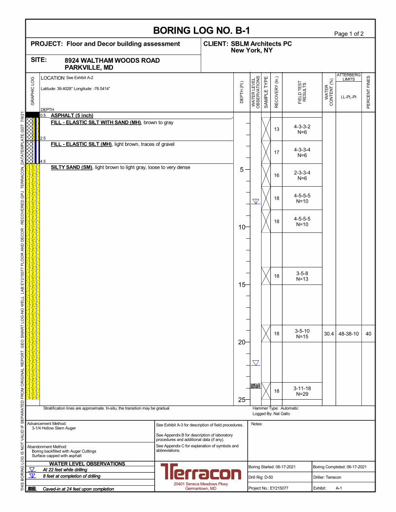
We drilled two borings (B-1 and B-2) to a depth of 35 and 20 feet below existing grades,respectively, within the proposed loading dock and truck access driveway. Groundwater andborehole cave-in observations were made during drilling and at completion of each borehole. Fulldetails about the methods used to perform the explorations and obtain samples can be found inthe Exploration and Testing Procedures section.
1 Crowley, W.P., and Cleaves, E.T., 1974, Geologic map of the Towson quadrangle, Maryland: MarylandGeological Survey, Quadrangle Geologic Map QA-2

Geotechnical Engineering Report Rev-1Floor & Décor Building Investigation ■ Parkville, MarylandAugust 26, 2021 ■ Terracon Project No. EY215077
Responsive ■ Resourceful ■ Reliable 4
The location of GPR transects, slab core exploration locations, and coring logs are provided inthe Site Location and Exploration Plans and Exploration Results sections at the end of thisreport.
Geophysical Exploration
Terracon used a GPR system consisting of a Structure Scan Mini XT made by GeophysicalSurvey Systems, Inc. (GSSI), to perform an upper profile geophysical survey. In general, fielddata collection was accomplished as referenced in ASTM Standard D6432. More information onboth the general method and collection procedures can be found in the referenced standard.
Terracon explored the accessible areas within the main building slab and the garden shop,collecting data in one direction at 10-foot spacing, where possible. Due to the layout of the retailstore and existing interior obstructions, data was obtained by using multiple grids over the area.This technique involves collecting data in the field and taking it back to the office to be post-processed using RADAN software engineered by GSSI.
Geophysical Exploration Findings and Limitations
It should be noted that, as with any geophysical method, these processes rely on instrumentsignals to indicate physical conditions in the field. Signal information can be affected by on-siteconditions beyond the control of the operator. The limitations for this project application include:
■ Locations where data could not be collected due to obstructions were not able to becovered. These areas included walls and existing desks/counters.
■ Areas where the concrete thickness has rapid changes may not be shown on figures, dueto the limited area the change occurred.
Interpretation of signals is based on a combination of known factors combined with the experienceof the operator and geophysical scientist evaluating the results. Utilizing conventional observation,sampling, and testing of select areas are recommended to confirm the results from thegeophysical surveys. As with all geophysical methods, the geophysical results provide a level ofconfidence, but should not be considered absolute. We cannot be responsible for theinterpretation of geophysical results by others.
The results presented in this report are based upon the data obtained from the geophysicalsurveys and from other information discussed in this report. This report does not reflect variationsthat may occur in areas inaccessible to the geophysical equipment, across the site, or due to themodifying effects of construction or weather. The nature and extent of such variations may notbecome evident until during or after construction.

Geotechnical Engineering Report Rev-1Floor & Décor Building Investigation ■ Parkville, MarylandAugust 26, 2021 ■ Terracon Project No. EY215077
Responsive ■ Resourceful ■ Reliable 5
Floor Slab Investigation
We identified nine proposed slab exploration locations based on the GPR results and accessibilitywithin the commercial building. Each location was cored, then we used a hand auger to exploresubgrade conditions below the floor slab and performed dynamic cone penetrometer (DCP)testing up to a depth of 1 foot below ground surface at all core locations. Groundwater was notencountered within the explored depths. Samples of the subgrade soils were collected, fieldclassified, and taken to Terracon’s office and soil testing laboratory for additional evaluation andtesting. Full details about the methods used to perform the explorations and obtain samples canbe found in Exploration and Testing Procedures.
Concrete Core Thicknesses
A nominal 4-inch diameter concrete core was obtained at each location using a cored drill machineas noted in Subsurface Exploration Program section above. The cores were then measured toobtain the existing floor slab thickness and transported to our lab. The measured core thicknessresults are summarized in the table below and full details can be found on the coring logs in theExploration Results section.
Summary of Floor Slab Thickness
Core Location Thickness of Concrete Floor Slab Core (Inches)
C-1 5.5C-2 6.25C-3 4.0C-4 5.5C-5 3.75C-6 4.75C-7 3.75C-8 5.5C-9 4.75
Vapor barrier was encountered in core locations C-5 and C-7; however, aggregate base layerwas not encountered at any of the core locations. The measurements provided above representfloor slab thicknesses at the explored locations only. Variations in actual floor slab thickness islikely between exploration points and across other areas of the building due to either designfeatures or construction tolerances. Taking the average of the thickness measurements may notbe representative of the prevailing slab thickness due to potential for variations in the distributionof data obtained.

Geotechnical Engineering Report Rev-1Floor & Décor Building Investigation ■ Parkville, MarylandAugust 26, 2021 ■ Terracon Project No. EY215077
Responsive ■ Resourceful ■ Reliable 6
Hand Auger and DCP Evaluation
Dynamic cone penetrometer (DCP) tests were performed within subgrade soils at depths of oneto two foot below the floor slab, as noted on the coring logs. We found the subgrade soils belowthe bottom of floor slab to consist of existing fill, derived from the natural Potomac Group sandand clay deposits (Coastal Plain soils), consistent with anticipated conditions.
Based on the published correlation2 shown above between DCP blow counts over a 1.75-inchincrement and the SPT “N” value, the consistency of the generally Fine-grained subgrade soilsencountered below the floor slab at coring exploration locations is characterized as "soft to verystiff” based on the DCP test results. A summary of the DCP test results and correlations with theconsistency of the subgrade soils encountered is presented in the following table.
DCP Results (ASTM STP-399)
Hand AugerLocation Soil Encountered
TestDepth(feet)
DCP BlowCounts atTest Depth
Consistency Based onSPT Correlations
C-1 Sandy Silt (ML) 1.0 2-3-4 Soft to Medium Stiff
C-2 Sandy Silt with gravel (ML) 1.0 2-4-4 Medium Stiff
C-3 Silty SAND (SM) 1.0 3-4-5 Loose
C-4 Lean CLAY with sand (CL) 1.0 12-10-16 Stiff
C-5 Sandy SILT with gravel (ML) 1.0 5-9-7 Medium Stiff
2 Dynamic Cone Penetrometer Set, product manual H-4202A_MAN_4.17

Geotechnical Engineering Report Rev-1Floor & Décor Building Investigation ■ Parkville, MarylandAugust 26, 2021 ■ Terracon Project No. EY215077
Responsive ■ Resourceful ■ Reliable 7
DCP Results (ASTM STP-399)
Hand AugerLocation Soil Encountered
TestDepth(feet)
DCP BlowCounts atTest Depth
Consistency Based onSPT Correlations
C-6 Sandy SILT with gravel (ML) 1.0 2-5-4 Medium Stiff
C-7 Sandy SILT with gravel (ML) 1.0 10-22-16 Stiff to Very Stiff
C-8 Sandy SILT with gravel (ML) 1.0 6-11-8 Stiff
C-9 Sandy SILT with gravel (ML) 1.0 7-7-7 Medium stiff
Concrete Core Compressive Strength Tests Results
Two concrete core specimens obtained from the existing floor slab was tested for compressivestrength. The results of the test are summarized in the table below:
Core Location Concrete Core Compressive Strength (psi) 1
C-1 3,700
C-2 6,060
1. Performed in general accordance with ASTM C42 with appropriate L/D corrections applied.
Subsurface Conditions
We have developed a general characterization of the subsurface conditions within the site basedupon our review of the subsurface exploration and laboratory data, and our understanding of thegeologic setting.
Conditions encountered in the borings and hand augers are presented in the ExplorationResults section. Stratification boundaries on the boring and coring logs represent theapproximate location of changes in materials types; in situ, the transition between materials maybe gradual.
We identified the following material layers during our field investigation:
Layer Layer Name General Description
1Asphalt
(0 to 0.5 feet)Borings performed within pavements (B-1 and B-2) encountered2.5 and 5 inches of asphalt.

Geotechnical Engineering Report Rev-1Floor & Décor Building Investigation ■ Parkville, MarylandAugust 26, 2021 ■ Terracon Project No. EY215077
Responsive ■ Resourceful ■ Reliable 8
Layer Layer Name General Description
2Existing Fill(0 to 4.5 feet)
Elastic SILT (MH), Sandy SILT (ML), and Lean CLAY (CL) withvarying amounts of sand and gravel.
3Coarse-Grained Soils
(4.5 to 35 feet)Silty SAND (SM) with varying amounts of clay and gravel. Relativedensity varies between loose to very dense.
Existing Building Slab
Based on interpretation of the results of our GPR transects, and measurements at the slab coringexploration locations, the thickness of the concrete floor slab varies between 3 to 6.25 inches. Wedid not encounter the presence of reinforcing steel bars within the floor slab at any of the coringlocations.
Groundwater Conditions
Groundwater levels and cave-in depths were recorded during drilling and at the completion ofdrilling at each borehole location. Groundwater was encountered during drilling in boring B-1 at adepth of 22 feet and upon completion at a depth of 8 feet. Groundwater was not encountered inBoring B-2 during drilling or upon completion. Cave-in depths for borings B-1 and B-2 were 24and 10 feet below ground surface, respectively.
Perched groundwater may be encountered at shallow depths. Fluctuations in perched orgroundwater levels should be expected with variations in conditions such as precipitation,evaporation, construction activity, etc.
GEOTECHNICAL OVERVIEW
The soil borings performed for this study indicate presence of approximately 4.5 feet of existingfill within the proposed loading dock area. In our opinion, these materials are not suitable for directsupport of new foundations, due to the potential for unacceptable settlement resulting frominherent variations in the nature and consistency of the existing fill.
In order to support the proposed loading dock walls on a conventional shallow foundation system,we recommend removing the existing fill and replacing it with structural fill or lean concrete to theproposed foundation subgrade level. Provided that the fill is removed and replaced with structuralfill or lean concrete, as further discussed in the Earthwork section below, the proposed loadingdock additions can be supported on shallow foundations bearing on medium dense silty sands,structural fill, or lean concrete. The Shallow Foundations section provides foundationrecommendations.

Geotechnical Engineering Report Rev-1Floor & Décor Building Investigation ■ Parkville, MarylandAugust 26, 2021 ■ Terracon Project No. EY215077
Responsive ■ Resourceful ■ Reliable 9
If required, it may be possible to support pavements and floor slabs on the existing fill material onthe silty encountered in our study. However, since the nature and density of the entire fill layerhas not been confirmed, there will be a risk that the post-construction performance of thepavements and slab will not be as desired, especially if the new loads are greater than the priorloads. This risk cannot be eliminated without full depth ground improvement of the existing fill.However, to take advantage of the cost benefit of not performing a full depth removal andreplacement of the existing fill, the owner must be willing to accept this risk. The partial excavationand replacement procedure to mitigate the effects of non-uniform compaction under the slab areoutlined in Floor Slabs section, and the subgrade preparation recommendations for new exteriorpavements, as well as a mill and overlay option, are discussed in the PavementRecommendations section. The Earthwork section addresses the site and subgradepreparation recommendations..
The General Comments section provides an understanding of the report limitations.
SEISMIC CONSIDERATIONSThe seismic design requirements for buildings and other structures are based on Seismic DesignCategory. Site Classification is required to determine the Seismic Design Category for a structure.
The Site Classification is based on the upper 100 feet of the site profile defined by a weightedaverage value of either shear wave velocity, standard penetration resistance, or undrained shearstrength in accordance with Section 20.4 of ASCE 7 and the International Building Code (IBC)and are presented in the following table.
Site Class vs (ft/sec) N or Nch su (psf)
A. Hard rock >5,000 NA NA
B. Rock 2,500 to 5,000 NA NA
C. Very dense soil and soft rock 1,200 to 2,500 >50 >2,000
D. Stiff soil 600 to 1,200 15 to 50 1,000 to 2,000
E. Soft clay soil 1 <600 <15 <1,000

Geotechnical Engineering Report Rev-1Floor & Décor Building Investigation ■ Parkville, MarylandAugust 26, 2021 ■ Terracon Project No. EY215077
Responsive ■ Resourceful ■ Reliable 10
Site Class vs (ft/sec) N or Nch su (psf)
F. Soils requiring site responseanalysis
■ Soils vulnerable to potential failure or collapse under seismicloading, such as liquefiable soils, quick and highly sensitiveclays, and collapsible weakly cemented soils 2.
■ Peats and/or highly organic clays (H>10 ft or 3 m), whereH=thickness of soil
■ Very high plasticity clays (H>25 ft with PI>75
■ Very thick soft/medium stiff clays (H>120 ft with su<1,000 psf)
1. Any profile with more than 10 feet of soil having the following characteristics:· Plasticity index, PI > 20· Moisture content, w > 40 percent· Undrained shear strength, su < 500 psf
2. Subject to exceptions stated in Section 20.3.1 in Chapter 20 of ASCE 7.
Based on the properties of subsurface materials encountered at the site, it is our opinion that theSeismic Site Classification for the site is D. Subsurface explorations at the site were extended toa maximum depth of 35 feet. The properties and age of the geologic formational materialsencountered below the bottom of the deepest borings at the site to a depth of 100 feet wereestimated based on our experience and knowledge of geologic conditions of the general area. Ifit is desired to optimize the seismic site classification, additional deeper borings or geophysicalshear wave velocity testing may be performed to confirm the conditions below the deepest currentboring depth.
EARTHWORK
Earthwork is anticipated to include clearing, demolition, excavations, and fill placement. Thefollowing sections provide recommendations for use in the design and preparation ofspecifications for the work. Recommendations include critical quality criteria, as necessary, toprepare the site consistent with our geotechnical engineering recommendations for the structuresand their associated pavements.
Site Preparation
Any subsurface utilities and abandoned subsurface structures should be excavated and removedor relocated within and extended laterally at least 5 feet beyond the limits of the proposedconstruction area. The concrete and asphalt pavement within the construction area should bestripped within, as well as five feet beyond the limits of the proposed construction after the removaland relocation of utilities. The pavement is not suitable for reuse as structural fill/backfill andshould be disposed in a suitable manner.

Geotechnical Engineering Report Rev-1Floor & Décor Building Investigation ■ Parkville, MarylandAugust 26, 2021 ■ Terracon Project No. EY215077
Responsive ■ Resourceful ■ Reliable 11
As noted in Geotechnical Characterization section, existing fill was encountered in all boringsup to 4.5 feet below existing grades. Existing fill is not suitable for support of loading dockfoundations. Where encountered within any planned new foundation locations for the loading dockupgrades, existing fill needs to be over-excavated to the native, undisturbed soils and replacedwith compacted structural fill.
Subgrade Preparation
The Geotechnical Engineer or the Geotechnical Engineer’s authorized representative shouldevaluate the suitability of the exposed subgrades prior to fill placement or construction offoundation elements, pavement and slabs. In unconfined areas, the stripped subgrades shouldbe proofrolled with a fully loaded, tandem-axle dump truck to evaluate the subgrade suitabilityprior to any undercutting or initiation of fill placement. Areas that exhibit excessive pumping,weaving, or rutting should be scarified, dried, and recompacted, or undercut and replaced withcompacted structural fill as recommended by the Geotechnical Engineer. In confined areas,subgrade evaluation techniques could include a combination of probing with a penetrometer,drilling hand augers, or observing test pits excavations.
Upon completion of filling and grading, care should be taken to maintain the subgrade watercontent prior to construction of floor slabs and pavements. Construction traffic over the completedsubgrades should be avoided. The site should also be graded to prevent ponding of surface wateron the prepared subgrades or in excavations. Water collecting over or adjacent to constructionareas should be removed. If the subgrade freezes, desiccates, saturates, or is disturbed, theaffected material should be removed, or the materials should be scarified, moisture conditioned,and recompacted prior to construction.
Based on the exploration results, groundwater was encountered in boring B-1 at a depth of 8 feetbelow ground surface. The contractor should anticipate encountering shallow groundwater duringexcavation and effective site drainage measures should be installed early in the constructionsequence and maintained after construction to avoid potential drainage-related issues.Temporary dewatering measures such as sump pumps should be planned during constructionand water should be maintained at least 2 feet below the footing, floor slab, sidewalks andpavement subgrade at all times.
Excavation Safety
As a minimum, excavations should be performed in accordance with OSHA 29 CFR, Part 1926,Subpart P, “Excavations” and its appendices, and in accordance with any applicable local, and/orstate regulations.
Construction site safety is the sole responsibility of the contractor who controls the means,methods, and sequencing of construction operations. Under no circumstances shall theinformation provided herein be interpreted to mean Terracon is assuming responsibility for

Geotechnical Engineering Report Rev-1Floor & Décor Building Investigation ■ Parkville, MarylandAugust 26, 2021 ■ Terracon Project No. EY215077
Responsive ■ Resourceful ■ Reliable 12
construction site safety, or the contractor's activities; such responsibility shall neither be impliednor inferred.
Structural Fill
In the event that structural fill is needed to complete the backfill or site grading, we recommendthat the material be imported to the site and consist of inorganic, readily compactable, well-gradedgranular soils with no more than 15 percent fines (no more than 15 percent passing the No. 200sieve). Additionally, we recommend excluding aggregate that contains particle sizes greater than6 inches.
Structural Fill Placement
Structural fill should be installed in controlled layers uniformly compacted to at least 95 percent ofthe fill material’s maximum dry density, as determined by ASTM D1557 Test Procedures. Thelayer thickness should be adjusted as needed depending on the type of compaction equipmentused and the condition of the fill materials at the time of construction but should be no greaterthan 12 inches in loose thickness. It should be expected that thinner lifts will be required to achievethe required compaction in confined areas where portable compaction equipment is used. Themoisture content of the fill material should be controlled to within approximately 2 to 3 percent ofthe optimum moisture content by wetting, aeration, or blending, as necessary to achieve therequired compaction. Lean concrete or nominally compacted, clean, crushed stone could be usedin lieu of structural fill.
SHALLOW FOUNDATIONS
The loading dock upgrades may require new foundations for the sidewalls and canopy. If the sitehas been prepared in accordance with the requirements noted in Earthwork section, the followingdesign parameters are applicable for loading dock shallow foundations.
Design Parameters – Compressive Loads
Item Description
Maximum Net Allowable Bearing Pressure 1, 2 3,000 psf
Required Bearing Stratum 3 New structural fill or suitable, firm natural soils
Minimum Foundation WidthIsolated columns: 24 inchesContinuous wall footings: 18 inches
Ultimate Coefficient of Sliding Friction 4 0.4 (granular material)
Minimum Embedment below Finished Grade 5 For frost protection and protectiveembedment in unheated areas
30 inches

Geotechnical Engineering Report Rev-1Floor & Décor Building Investigation ■ Parkville, MarylandAugust 26, 2021 ■ Terracon Project No. EY215077
Responsive ■ Resourceful ■ Reliable 13
Item DescriptionFor interior footings in heatedareas
18 inches
Estimated Total Settlement from Structural Loads 2 1 inch
Estimated Differential Settlement 2 Less than 0.5 inch
1. The maximum net allowable bearing pressure is the pressure in excess of the minimum surroundingoverburden pressure at the footing base elevation. An appropriate factor of safety has been applied. Thesevalues are for building foundations.
2. Values provided are for maximum loads noted in Project Description. The actual magnitude of settlement thatwill occur beneath the foundations will depend upon the variations within the subsurface soil profile and thestructural loading conditions. The estimated total and differential settlements listed assume that the foundation-related earthwork and the foundation design are completed in accordance with the recommendations containedin this report.
3. Existing fill, unsuitable, or soft soils should be over-excavated and replaced according to the recommendationspresented in the Earthwork section.
4. Can be used to compute sliding resistance where foundations are placed on suitable soil/materials. Anappropriate factor of safety should be used. Should be neglected for foundations subject to net uplift conditions.
5. Embedment necessary to minimize the effects of frost and/or seasonal water content variations. For slopingground, maintain depth below the lowest adjacent exterior grade within 5 horizontal feet of the structure.
Construction Adjacent to Existing Building
Differential settlement between the loading dock additions and the existing building is expectedto approach the magnitude of the total settlement of the addition. Expansion joints or other suitablestructural accommodation, as determined by the structural engineer, should be provided betweenthe existing building and the proposed additions to accommodate differential movements betweenthe two structures. Underground piping between the two structures, if required, should bedesigned with flexible couplings and utility knockouts in foundation walls should be oversized, sominor deflections in alignment do not result in breakage or distress.
Care should be taken during excavation adjacent to existing foundations, to avoid disturbingexisting foundation bearing soils. New footings constructed immediately adjacent to existingfoundations should be established at the same bearing elevation as those of the immediatelyadjacent existing foundations and should have design bearing pressures no greater than those ofthe existing foundations. If these conditions are not possible, underpinning and or specialstructural and geotechnical evaluation of the foundations and subgrades may be required.
Foundation Construction Considerations
As noted in Earthwork section, the footing excavations should be evaluated under the directionof the Geotechnical Engineer or the Geotechnical Engineer’s authorized representative. Theinspection should consist of probing or performing Dynamic Cone Penetrometer (DCP) tests in

Geotechnical Engineering Report Rev-1Floor & Décor Building Investigation ■ Parkville, MarylandAugust 26, 2021 ■ Terracon Project No. EY215077
Responsive ■ Resourceful ■ Reliable 14
each of the footing excavations. The base of all foundation excavations should be free of waterand loose soil, prior to placing concrete. Footing subgrades should be protected fromprecipitation, seepage, surface run-off, and freezing temperature. Concrete should be placedsoon after excavating to reduce bearing soil disturbance. Care should be taken to prevent wettingor drying of the bearing materials during construction. Excessively wet or dry material or anyloose/disturbed material in the bottom of the footing excavations should beremoved/reconditioned before foundation concrete is placed.
If existing fill or unsuitable bearing soils (soft or deleterious materials) are encountered at the baseof the planned footing excavation, the excavation should be extended deeper to suitable soils.The footings could bear directly on these soils at the lower level or on lean concrete backfill placedin the excavations. This is illustrated on the following sketch.
A slope of 1.5H: 1V or flatter should be maintained between the bottom edges of adjacent footings.Footing and structural fill subgrades should be observed and approved by the GeotechnicalEngineer prior to placement of the concrete or new fill. Construction of utilities, roadways, andother associated structures should be delayed as much as possible after the completion ofbuilding.
Over-excavation for structural fill placement below footings should be conducted as shown below.The over-excavation should be backfilled up to the footing base elevation, with structural fillplaced, as recommended in the Earthwork section.

Geotechnical Engineering Report Rev-1Floor & Décor Building Investigation ■ Parkville, MarylandAugust 26, 2021 ■ Terracon Project No. EY215077
Responsive ■ Resourceful ■ Reliable 15
FLOOR SLABS
We recommend that the structural engineer should evaluate the structural integrity of the existingfloor slab to support new loading. As discussed in a previous section of this report, existing fillwas encountered in hand augers performed below the floor slab to a depth of 1.5 feet. Shouldexisting floor slabs be re-used in their current condition with new additional floor slab loads, weanticipate a higher risk of differential settlement and cracking of the floor slabs due to the presenceof existing, undocumented fill that comprise the soil subgrades, as well as the absence of aconsistent aggregate base course section and steel reinforcement within the slab.
Where it is determined by others that new floor slabs are required, we recommend that floor slabsubgrades be undercut at least 1 foot, proofrolled or probed as previously discussed, andreplaced with new structural fill to prevent potential differential settlement and cracking of the floorslabs. It is possible that loose conditions within the existing fill may be encountered at somelocations below the existing floor slab and localized stabilization of new fill subgrades may berequired, such as placement of geotextile and crushed stone over the loose fill subgrades. TheGeotechnical Engineer should be consulted for additional consideration should these conditionsbe encountered. We expect that the existing fill soils encountered in the hand augers may be re-used for new structural fill. We also recommend that an appropriate aggregate base coursesection below proposed floor slabs be provided over the soil subgrades.
We recommend the following design parameters for floor slabs, constructed over properlycompacted structural fill subgrades. Specific attention should be given to positive drainage awayfrom the structure and positive drainage of the aggregate base beneath the floor slab.

Geotechnical Engineering Report Rev-1Floor & Décor Building Investigation ■ Parkville, MarylandAugust 26, 2021 ■ Terracon Project No. EY215077
Responsive ■ Resourceful ■ Reliable 16
Recommended Floor Slab Design Parameters
Item Description
Floor Slab Support 1 Minimum 6 inches of free-draining crushed aggregate tamped and densified
Estimated Modulus ofSubgrade Reaction 2 125 pounds per cubic inch (pci)
1. Floor slabs should be structurally independent of building footings or walls to reduce the possibility of floor slabcracking caused by differential movements between the slab and foundation.
2. The recommended modulus value for design is for a 1-ft-square plate and must be corrected for slab size. Theformula presented below should be used to calculate the appropriate modulus for foundations supported bygranular soils: Kb = Ks((b+1)/1b)2
Where: Kb = Corrected modulus (kcf) Ks = Modulus for 1-ft-square plate (kcf) b = Foundation width (ft)
The use of a vapor retarder should be considered beneath concrete slabs-on-grade covered witha moisture sensitive or impervious covering, or when the slab will support equipment sensitive tomoisture. When conditions warrant the use of a vapor retarder, the slab designer should refer toACI 302 and/or ACI 360 for procedures and cautions regarding the use and placement of a vaporretarder.
Saw-cut control joints should be placed in the slab to help control the location and extent ofcracking. For additional recommendations refer to the ACI Design Manual. Joints or cracks shouldbe sealed with a waterproof, non-extruding compressible compound specifically recommendedfor heavy duty concrete pavement and wet environments.
Floor Slab Construction Considerations
Finished subgrade, within and for at least 10 feet beyond the floor slab, should be protected fromconstruction traffic, rutting, or other disturbance and maintained in a relatively moist condition untilfloor slabs are constructed. If the subgrade should become damaged or desiccated prior toconstruction of floor slabs, the affected material should be removed, and structural fill should beadded to replace the resulting excavation. Final conditioning of the finished subgrade should beperformed immediately prior to placement of the floor slab support course.
The Geotechnical Engineer should approve the condition of the floor slab subgrades immediatelyprior to placement of the floor slab support course, reinforcing steel, and concrete. Attentionshould be paid to high traffic areas that were rutted and disturbed earlier, and to areas wherebackfilled trenches are located.

Geotechnical Engineering Report Rev-1Floor & Décor Building Investigation ■ Parkville, MarylandAugust 26, 2021 ■ Terracon Project No. EY215077
Responsive ■ Resourceful ■ Reliable 17
FOUNDATION / RETAINING WALLS
Design Parameters
The loading dock upgraded may incorporate foundation/retaining walls if a recessed loading dockis planned. Structures with unbalanced backfill levels on opposite sides should be designed forearth pressures at least equal to values indicated in the following table. Earth pressures will beinfluenced by structural design of the foundation walls, conditions of wall restraint, methods ofconstruction, and/or compaction and the strength of the materials being restrained. Two wallrestraint conditions are shown in the diagram below.
We recommend that these unbalanced foundation/retaining walls be designed as a free-standingretaining wall that is free to move at the top. Free-standing retaining walls should be designedusing active earth pressures (Ka) as shown in the table below. The “at-rest” condition assumesno wall movement and is commonly used for basement walls, loading dock walls, or other wallsrestrained at the top.
Lateral Earth Pressure Design ParametersEarth
PressureConditions
Coefficient ofLateral Earth
Pressure
Equivalent FluidDensity (pcf)
Pressure due toVertical Surcharge,
p1 (psf)
Earth Pressure, p2
(psf)
Active (Ka) 0.33 40 (0.33) S (40) HAt-Rest (Ko) 0.5 60 (0.5) S (60) HPassive (Kp) 3.0 360 -- --
Existing Grade
Foundation Wall

Geotechnical Engineering Report Rev-1Floor & Décor Building Investigation ■ Parkville, MarylandAugust 26, 2021 ■ Terracon Project No. EY215077
Responsive ■ Resourceful ■ Reliable 18
The recommended earth pressure coefficients are based on the following assumptions andconsiderations:
■ For active earth pressures to develop, the wall must rotate about its base, with lateralmovements at the top of about 0.002H to 0.004H, where H is wall height.
■ For passive earth pressure to develop, wall must move horizontally to mobilize resistance.
■ Loadings from surcharges or sloping backfill above the wall will need to be added to theequivalent fluid pressures provided above.
■ Active pressures are based on structural fill being used as backfill with a maximum totalunit weight of 120 pcf and a friction angle of 30˚. Passive pressures are based on existingfill or natural soils with a maximum total unit weight of 120 pcf and a friction angle of 30˚.
■ Structural fill should be free-draining and placed in accordance with the recommendationspresented in the Earthwork section.
■ Hand-operated/walk-behind compaction equipment must be used within a lateral distanceequal to the height of the wall or five feet, whichever is greater, to reduce the potential forexcessive lateral pressures or wall deformations.
■ The pressures provided above are ultimate values. No safety factor has been applied.Appropriate safety factors should be applied by the wall designer.
■ Passive pressures should be ignored within the frost zone.
To calculate the resistance to sliding, a value of 0.3 should be used as the ultimate coefficient offriction between the wall footing and the underlying soil. An appropriate factor of safety should beapplied to this value. This value also assumes that a pavement drain has been installed in theloading dock to prevent surface water flow from ponding at the base of the ramp and infiltratinginto the subgrade soils below the loading dock.
Construction Considerations
We anticipate that seasonal perched groundwater levels may rise to foundation elevations duringthe wet periods of the year. Therefore, exterior foundation drains are required around theperimeter of the loading dock walls. The exterior drain should consist of a 4-inch perforated flexibletube embedded in 12 inches of AASHTO #57 stone or washed bank run gravel. The stone shouldbe wrapped with filter fabric to avoid clogging with fines. The drains should drain to the sumppump or daylight to an appropriate location as determined by the Civil Engineer.
We also recommend that finished grades around the loading dock walls be positively sloped at agradient of not less than 5 percent.

Geotechnical Engineering Report Rev-1Floor & Décor Building Investigation ■ Parkville, MarylandAugust 26, 2021 ■ Terracon Project No. EY215077
Responsive ■ Resourceful ■ Reliable 19
PAVEMENT RECOMMENDATIONS
Its our understanding from discussions with SBLM and Kinley-Horn, that pavement renovationsare planned for the site and are only required to extend the design life 5 years. Full depthpavement reconstruction with flexible or rigid pavement is recommended for the truck accessdriveways and loading areas. Proposed pavements are designed for large delivery vehicles. Ifheavier traffic loading is expected, Terracon should be provided with that information and allowedto review and revise the recommended pavement sections.
We also recommend performing the following repairs to the existing pavement within the existingdriveways and parking lots in front of the building:
■ Milling the existing asphalt pavement to a depth of 1 inch and overlaying with new 1.5inches of asphalt within the customer parking lots and drive areas.
The paragraphs below describe each repair option in more details. Pavement designs noted inthis section must be applied to the site which has been prepared as recommended in theEarthwork section.
Full Depth Pavement Reconstruction
Based on our field exploration program, aggregate base was not encountered in either of theborings drilled and existing asphalt thickness varied from 2.5 to 5 inches. Based on our visualinspection of the asphalt, alligator cracking was observed within the pavement to the northside ofthe building. The pavement deficiencies that are associated with the soil instability are caused bysubgrade disturbance (i.e. trench or inlet excavation) or by subgrade softening caused byaccumulation of water that seeps through the pavement cracks and load and vibrations fromvehicle traffic. Because of the lack of aggregate base and subgrade instability, we recommendthat the existing pavement section be removed in the proposed truck access driveways, followedby cutting or regrading the areas to accommodate the new pavement sections recommendedbelow. The exposed pavement subgrade should be thoroughly proofrolled under the observationof a Terracon geotechnical engineer as discussed in Earthwork section of this report.
If existing fill zones of soft soils are encountered, or subgrades are disturbed as a result ofconstruction activities or weather, the subgrade will need to be selectively undercut at least 12inches into firm existing fill/natural soils, proofrolled, and replaced with new compacted structuralfill. If anticipated undercutting of pavement subgrades exceeds 2 to 3 feet, the GeotechnicalEngineer should be consulted for additional consideration.
Areas not in compliance with the required ranges of moisture or density should be moistureconditioned and re-compacted. Areas where unsuitable conditions are present should be repairedby removing and replacing the materials with properly compacted fills that meet the requirements

Geotechnical Engineering Report Rev-1Floor & Décor Building Investigation ■ Parkville, MarylandAugust 26, 2021 ■ Terracon Project No. EY215077
Responsive ■ Resourceful ■ Reliable 20
indicated in Earthwork section of this report. If a significant precipitation event occurs after theevaluation, or if the surface becomes disturbed, the subgrade should be reviewed by theGeotechnical Engineer or the Geotechnical Engineer’s authorized representative immediatelyprior to paving. The subgrade should be in its finished form at the time of the final review.
Minimum Pavement Recommendations
A design CBR value of 3 was used in our pavement thickness determination. Additional testing isrecommended during construction to confirm the soils placed within the upper 1 foot of theproposed subgrade exhibit a field CBR value equal to or greater than 3. To help obtain this CBRvalue for the onsite soils, the upper 1 foot of pavement subgrades should be compacted to atleast 100% of the standard proctor maximum dry density at a moisture content within 2% of itsoptimum moisture.
We recommend the following minimum flexible pavement sections in parking lots and accessroads.
Pavement LayerFlexible Pavement Thickness Rigid Pavement Thickness
Light Duty (newparking lots)
Heavy Duty (truckaccess driveway)
Standard Duty (customerpickup area)
Portland ConcreteCement (PCC) 5.0
Bituminous SurfaceCourse (Asphalt) 1.5 1.5
Bituminous BaseCourse (Asphalt) 2.5 3.0
Graded AggregateBase (GAB) Course 4.0 6.0 4.0
Pavement materials and construction methods should comply with the AASHTO specifications.Recommendations for pavement construction presented depend upon compliance withrecommended material specifications. To assess compliance, observation and testing should beperformed under the direction of the Geotechnical Engineer.
Prior to placement of the aggregate base course material, the pavement subgrade areas shouldbe thoroughly proofrolled as discussed above.
Mill and Overlay Recommendations
Based on the provided information, a mill and overlay procedure is recommended for customerparking lot and drive areas to extend the life of the pavement another 5 years. Following millingof 1 inches of asphalt from the recommended areas, the milled sections of roadway should be

Geotechnical Engineering Report Rev-1Floor & Décor Building Investigation ■ Parkville, MarylandAugust 26, 2021 ■ Terracon Project No. EY215077
Responsive ■ Resourceful ■ Reliable 21
proofrolled with a loaded tandem-axle dump truck or similar pneumatic-tired equipment weighing10 to 12 tons to identify any weak, yielding or pumping base. If such areas are encountered, theremaining existing pavement in these identified areas should be entirely removed, and thesubgrades prepared as discussed in the Full Depth Pavement Reconstruction section above.
After the proofroll is completed, the milled areas should be inspected for cracks with widthsexceeding approximately 3/16 inch. These wide cracks should be properly sealed to minimizereflective cracking. Even with the recommended crack sealing, the occurrence of some reflectivecracking should be anticipated with an overlay program. The new overlay should consist of 1.5inches of surface course asphalt.
To extend the life of the pavement we recommend installing Glasgrid® asphalt reinforcementsystem between the base course and the surface course of the asphalt overlay. The Glasgridsystem acts as a hidden strength within the road, turning vertical crack stresses horizontally toeffectively dissipate them.
Pavement Drainage
Water that is allowed to pond within or below the pavement, or adjacent to the pavements couldsaturate the subgrade and contribute to premature pavement deterioration. Based on therelatively poor permeability of native soils, it is possible that perched water can accumulate withinand below the pavement; therefore, we recommend installing a pavement subdrain system tocontrol groundwater, improve stability, and improve long-term pavement performance.
The pavement subdrain system should be installed in the low-lying areas which are especiallyprone to deterioration, and appropriate sub-drainage connected to a suitable outlet should beprovided to remove water from the granular subbase and fill layer. Periodic maintenance ofsubdrains is required for long-term proper performance.
Crack Sealing
The life of the pavement outside the areas designated for full depth replacement and mill andoverlay can be extended by sealing the existing cracks. This measure should be performed as afirst step of ongoing pavement maintenance program as discussed below.
Pavement Maintenance
Following pavement repair periodic maintenance should be anticipated. Preventive maintenanceshould be planned and provided for through an on-going pavement management program.Maintenance activities are intended to slow the rate of pavement deterioration, and to preservethe pavement investment. Maintenance consists of both localized maintenance (e.g., crack andjoint sealing and patching) and global maintenance (e.g., surface sealing). Preventivemaintenance is usually the first priority when implementing a pavement maintenance program.

Geotechnical Engineering Report Rev-1Floor & Décor Building Investigation ■ Parkville, MarylandAugust 26, 2021 ■ Terracon Project No. EY215077
Responsive ■ Resourceful ■ Reliable 22
Even with periodic maintenance, some movements and related cracking may still occur andrepairs may be required. Geosynthetic reinforcement could be considered to extend the length oftime before maintenance is required.
ENGINEERING SERVICES DURING CONSTRUCTION
Recommendations provided in this report are based on the information obtained from thesubsurface exploration and laboratory testing. However, conditions on the site may vary betweenthe discrete locations that were observed at the time of our subsurface exploration. The natureand extent of variations between test locations may not become evident until during construction.
To account for this variability, Terracon should provide construction observation and testing ofsubsurface conditions revealed during construction as an extension of our engineering servicesas the geotechnical engineer. These services will also help in evaluating the Contractor'sconformance with the plans and specifications. Because of our understanding of the intent of thegeotechnical engineering recommendations, retaining Terracon for these services will allow us toprovide consistent service throughout the project construction.
Construction phase monitoring services may include, but are not limited to, observation of theinstallation of floor slab subgrades, and placement and compaction of all fill materials. Theseservices should be performed by an authorized representative working under supervision of theprofessional Geotechnical Engineer.
GENERAL COMMENTS
This report has been prepared for the exclusive use of our client for specific application to theproject discussed and has been prepared in accordance with generally accepted geophysical andgeotechnical practices. No warranties, either express or implied, are intended or made.
Our analysis and opinions are based upon our understanding of the project, the geotechnicalconditions in the area, and the data obtained from our site exploration. Natural variations will occurbetween exploration point locations or due to the modifying effects of construction or weather.The nature and extent of such variations may not become evident until during or after construction.
Terracon should be retained as the Geotechnical Engineer, where noted in this report, to provideobservation and testing services during pertinent construction phases. If variations appear, wecan provide further evaluation and supplemental recommendations. If variations are noted in theabsence of our observation and testing services on-site, we should be immediately notified sothat we can provide evaluation and supplemental recommendations.
Our Scope of Services does not include either specifically or by implication any environmental orbiological (e.g., mold, fungi, bacteria) assessment of the site or identification or prevention of

Geotechnical Engineering Report Rev-1Floor & Décor Building Investigation ■ Parkville, MarylandAugust 26, 2021 ■ Terracon Project No. EY215077
Responsive ■ Resourceful ■ Reliable 23
pollutants, hazardous materials, or conditions. If the owner is concerned about the potential forsuch contamination or pollution, other studies should be undertaken.
Our services and any correspondence or collaboration through this system are intended for thesole benefit and exclusive use of our client for specific application to the project discussed andare accomplished in accordance with generally accepted geotechnical engineering practices withno third-party beneficiaries intended. Any third-party access to services or correspondence issolely for information purposes to support the services provided by Terracon to our client.Reliance upon the services and any work product is limited to our client and is not intended forthird parties. Any use or reliance of the provided information by third parties is done solely at theirown risk. No warranties, either express or implied, are intended or made.
Site characteristics as provided are for design purposes and not to estimate costs. Any use of ourreport in that regard is done at the sole risk of the cost estimator as there may be variations onthe site that are not apparent in the data that could significantly impact costs. Any parties chargedwith estimating excavation costs should seek their own site characterization for specific purposesto obtain the specific level of detail necessary for costing. Site safety and cost estimating are theresponsibility of others. If changes in the nature, design, or location of the project are planned,our conclusions and recommendations shall not be considered valid unless we review thechanges and either verify or modify our conclusions in writing.

Geotechnical Engineering ReportFloor & Décor Building Investigation ■ Parkville, MarylandAugust 26, 2021 ■ Terracon Project No. EY215077
Responsive ■ Resourceful ■ Reliable
ATTACHMENTS

Geotechnical Engineering ReportFloor & Décor Building Investigation ■ Parkville, MarylandAugust 26, 2021 ■ Terracon Project No. EY215077
Responsive ■ Resourceful ■ Reliable
EXPLORATION AND TESTING PROCEDURES
Field ExplorationNumber of Locations Type of Exploration Boring Depth (feet) Location
2 Borings 20 to 35 Future additions area9 Cores 0.2-1.5 Existing concrete slab
Boring Layout and Elevations: Based on the boring and coring map prepared by CenterpointIntegrated Solutions dated June 7, 2021. Terracon staked the borings on site using existing sitefeatures and dimensions measured of off the site layout. Approximate elevations were obtainedby interpolation from the from local USGS topographic maps.
Subsurface Exploration Procedures: The drilling and coring was performed on June 17th and18th, 2021, by Terracon. The two soil borings were advanced using a track-mounted D-50 ATVdrill rig, using 3¼-inch inner diameter hollow stem augers. Five Standard Penetration Test SPTsamples, using 24-inch long samplers, were obtained from 2 feet below the ground surface in theupper 10 feet of each boring. Sampling interval was increased to 5 feet thereafter (using 18-inchlong samplers) in all borings within footprint of building location.
In the split-barrel sampling procedure, a standard 2-inch outer-diameter split-barrel samplingspoon was driven into the ground by a 140-pound automatic hammer falling 30 inches. Thenumber of blows required to advance the sampling spoon the middle 12 inches of the typical total24-inch penetration or the last 12 inches of a normal 18-inch penetration is recorded as the SPTresistance value. The SPT resistance values, also referred to as N-values, are indicated on theboring logs at the test depths.
We observed and recorded groundwater levels during drilling and sampling. All borings werebackfilled with auger cuttings after completion.
The sampling depths, penetration distances, and other sampling information was recorded on thefield boring logs. The samples were placed in appropriate containers and taken to our soillaboratory for testing and classification by a Geotechnical Engineer. Our exploration teamprepared field boring logs as part of the drilling operations. These field logs included visualclassifications of the materials encountered during drilling and our interpretation of the subsurfaceconditions between samples. Final boring logs were prepared from the field logs. The final boringlogs represent the Geotechnical Engineer's interpretation of the field logs and includemodifications based on observations and tests of the samples in our laboratory.
Concrete Coring and DCP Procedures: On-site Terracon personnel cored the existing floorslab to its full depth using a core drill machine with a 4-inch core bit and measured the thicknessof the floor slab at all nine core locations. We then used a 2-inch diameter hand auger to exploresubgrade conditions below the floor slab and performed DCP testing up to a depth of 1 foot belowground surface at test locations C-1 through C-9. We used a S-2000 Sleeve drive hammer DCPto evaluate the in-place density of the underlying subgrade soils.

Geotechnical Engineering ReportFloor & Décor Building Investigation ■ Parkville, MarylandAugust 26, 2021 ■ Terracon Project No. EY215077
Responsive ■ Resourceful ■ Reliable
Laboratory Testing
We reviewed the field data and assigned laboratory tests on selected representative soil samplesto understand the engineering properties of the various soil strata, as necessary, for this project.
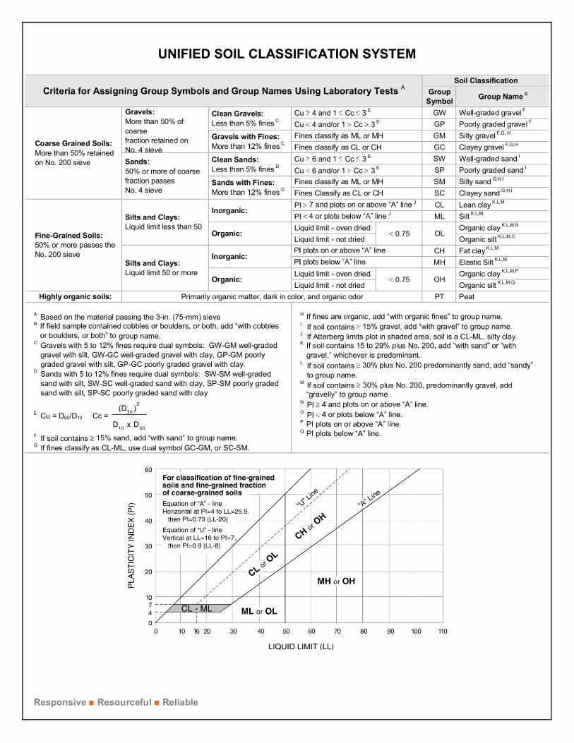
Based on the material’s texture and plasticity, we described and classified the soil samples inaccordance with the Unified Soil Classification System. Concrete core specimens retrieved fromeach core location are measured, and two representative cores were tested for compressivestrength.
Procedural standards noted below are for reference to methodology in general. In some cases,variations to methods were applied because of local practice or professional judgment. Standardsnoted below include reference to other, related standards. Such references are not necessarilyapplicable to describe the specific test performed.
n ASTM D2216 Standard Test Methods for Laboratory Determination of Water (Moisture)Content of Soil and Rock by Mass
n ASTM D4318 Standard Test Methods for Liquid Limit, Plastic Limit, and Plasticity Index ofSoils
n ASTM D422 Standard Test Method for Particle-Size Analysis of Soils
n ASTM C42 Unconfined Compressive Strength Test on Concrete Core
Geotechnical Engineering ReportFloor & Décor Building Investigation ■ Parkville, MarylandAugust 26, 2021 ■ Terracon Project No. EY215077
Responsive ■ Resourceful ■ Reliable
SITE LOCATION AND EXPLORATION PLANS
Contents:
Site Location PlanCoring and Boring Exploration Plan

SITE LOCATION PLANFloor & Décor Building Investigation ■ Parkville, MarylandAugust 26, 2021 ■ Terracon Project No. EY215077
Note to Preparer: This is a large table with outside borders. Just click inside the tableabove this text box, then paste your GIS Toolbox image.
When paragraph markers are turned on you may notice a line of hidden text above andoutside the table – please leave that alone. Limit editing to inside the table.
The line at the bottom about the general location is a separate table line. You can editit as desired, but try to keep to a single line of text to avoid reformatting the page.
MAP 1 PORTRA IT
DIAGRAM IS FOR GENERAL LOCATION ONLY, AND IS NOT INTENDED FOR CONSTRUCTION PURPOSES MAP PROVIDED BY MICROSOFT BING MAPS
Historical Terracon Projects

CORING AND BORING EXPLORATION PLANFloor & Décor Building Investigation ■ Parkville, MarylandAugust 26, 2021 ■ Terracon Project No. EY215077
MAP 1 LANDSCAPE 1 11X1 7 LANDSCAEP 2 PORTRAI TMAP 2 LANDSCAPEMAP 2 1 1X17 LANDSCAPE

Responsive ■ Resourceful ■ Reliable
EXPLORATION RESULTS
Contents:
GPR ResultsAsphalt and Concrete Core Photo Log (12 pages)General NotesUnified Soil Classification SystemBoring and Coring Logs (B-1, B-2 and C-1 through C-9) (12 pages)Atterberg LimitsGrain Size DistributionConcrete Test Results
Note: All attachments are one page unless noted above.

GPR Results
Floor and Decor Building AssessmentParkville, MD 1
20401 Seneca Meadows Pkwy Germantown, MD 20876
PH. (301) 354-6100
EY215077
JUNE 2021
AR
MC
EC
AS-SHOWN.
Project Manager:
Drawn by:
Checked by:
Approved by:
Project No.
Scale:
File Name:
Date:
EXHIBIT
--DIAGRAM IS FOR GENERAL LOCATION
ONLY, AND IS NOT INTENDED FOR
CONSTRUCTION PURPOSES
AR

20401 Seneca Meadows Pkwy Germantown, MD 20876
PH. (301) 354-6100 FAX. (301) 354-6101
FIG No.ASPHALT & CONCRETE CORE PHOTOGRAPHY LOGFLOOR & DÉCOR BUILDING INVESTIGATION
8924 WALTHAM WOODS RDPARKVILLE, MD
Photo No. Date Taken:Location:Description:
1 6/17/2021B-15-Inch full depth asphalt core retrieved from truck access driveway atB-1 location

20401 Seneca Meadows Pkwy Germantown, MD 20876
PH. (301) 354-6100 FAX. (301) 354-6101
FIG No.ASPHALT & CONCRETE CORE PHOTOGRAPHY LOGFLOOR & DÉCOR BUILDING INVESTIGATION
8924 WALTHAM WOODS RDPARKVILLE, MD
Photo No. Date Taken:Location:Description:
2 6/17/2021B-22.5-Inch full depth asphalt core retrieved from truck access driveway atB-2 location

20401 Seneca Meadows Pkwy Germantown, MD 20876
PH. (301) 354-6100 FAX. (301) 354-6101
FIG No.ASPHALT & CONCRETE CORE PHOTOGRAPHY LOGFLOOR & DÉCOR BUILDING INVESTIGATION
8924 WALTHAM WOODS RDPARKVILLE, MD
Photo No. Date Taken:Location:Description:
3 6/17/2021C-15.5-Inch full depth concrete core retrieved from floor slab at CR-3location

20401 Seneca Meadows Pkwy Germantown, MD 20876
PH. (301) 354-6100 FAX. (301) 354-6101
FIG No.ASPHALT & CONCRETE CORE PHOTOGRAPHY LOGFLOOR & DÉCOR BUILDING INVESTIGATION
8924 WALTHAM WOODS RDPARKVILLE, MD
Photo No. Date Taken:Location:Description:
4 6/18/2021C-26.25-Inch full depth concrete core retrieved from floor slab at C-2location
20401 Seneca Meadows Pkwy Germantown, MD 20876
PH. (301) 354-6100 FAX. (301) 354-6101
FIG No.ASPHALT & CONCRETE CORE PHOTOGRAPHY LOGFLOOR & DÉCOR BUILDING INVESTIGATION
8924 WALTHAM WOODS RDPARKVILLE, MD
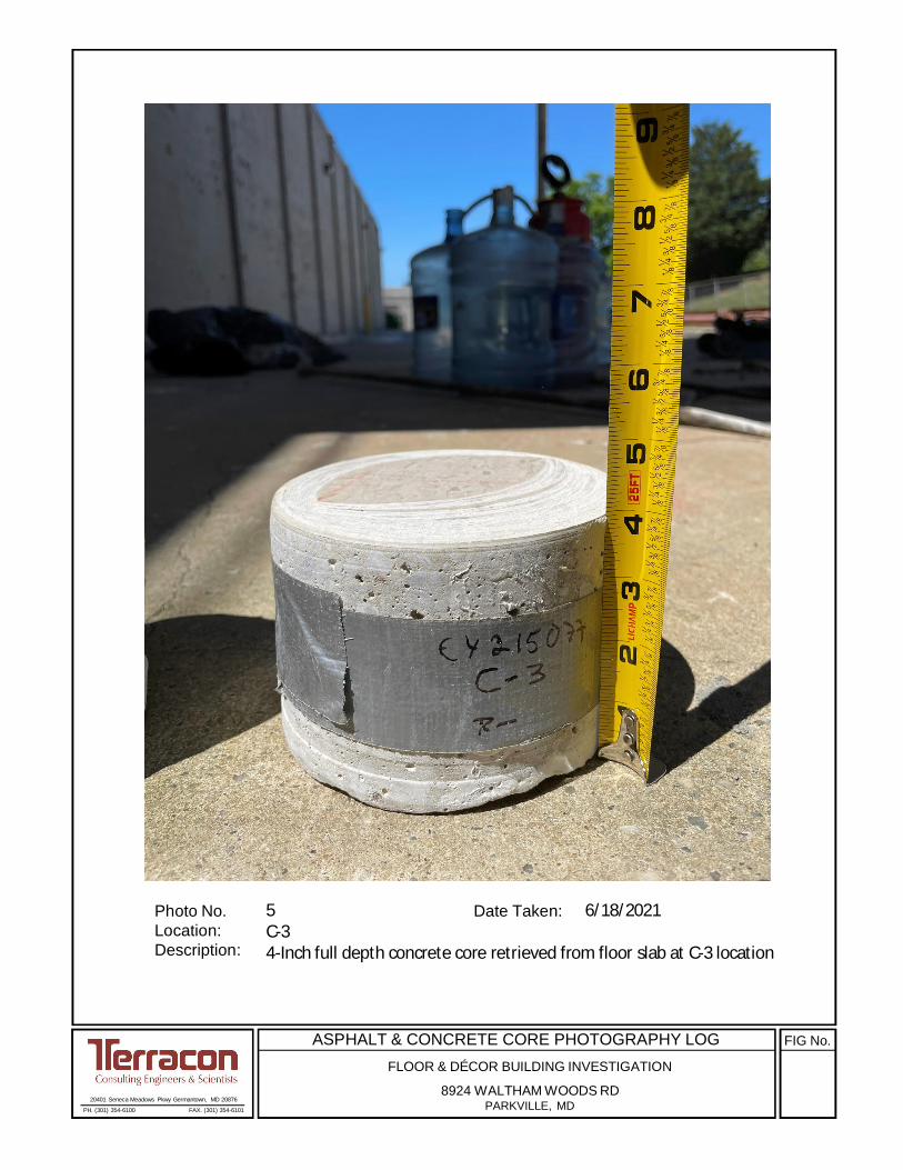
Photo No. Date Taken:Location:Description:
5 6/18/2021C-34-Inch full depth concrete core retrieved from floor slab at C-3 location

20401 Seneca Meadows Pkwy Germantown, MD 20876
PH. (301) 354-6100 FAX. (301) 354-6101
FIG No.ASPHALT & CONCRETE CORE PHOTOGRAPHY LOGFLOOR & DÉCOR BUILDING INVESTIGATION
8924 WALTHAM WOODS RDPARKVILLE, MD
Photo No. Date Taken:Location:Description:
6 6/18/2021C-45.5-Inch full depth concrete core retrieved from floor slab at C-4location
20401 Seneca Meadows Pkwy Germantown, MD 20876
PH. (301) 354-6100 FAX. (301) 354-6101
FIG No.ASPHALT & CONCRETE CORE PHOTOGRAPHY LOGFLOOR & DÉCOR BUILDING INVESTIGATION
8924 WALTHAM WOODS RDPARKVILLE, MD
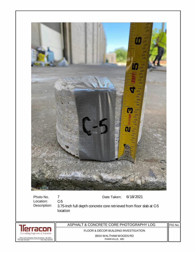
Photo No. Date Taken:Location:Description:
7 6/18/2021C-53.75-Inch full depth concrete core retrieved from floor slab at C-5location

20401 Seneca Meadows Pkwy Germantown, MD 20876
PH. (301) 354-6100 FAX. (301) 354-6101
FIG No.ASPHALT & CONCRETE CORE PHOTOGRAPHY LOGFLOOR & DÉCOR BUILDING INVESTIGATION
8924 WALTHAM WOODS RDPARKVILLE, MD
Photo No. Date Taken:Location:Description:
8 6/18/2021C-64.75-Inch full depth concrete core retrieved from floor slab at C-6location

20401 Seneca Meadows Pkwy Germantown, MD 20876
PH. (301) 354-6100 FAX. (301) 354-6101
FIG No.ASPHALT & CONCRETE CORE PHOTOGRAPHY LOGFLOOR & DÉCOR BUILDING INVESTIGATION
8924 WALTHAM WOODS RDPARKVILLE, MD
Photo No. Date Taken:Location:Description:
9 6/18/2021C-73.75-Inch full depth concrete core retrieved from floor slab at C-7location

20401 Seneca Meadows Pkwy Germantown, MD 20876
PH. (301) 354-6100 FAX. (301) 354-6101
FIG No.ASPHALT & CONCRETE CORE PHOTOGRAPHY LOGFLOOR & DÉCOR BUILDING INVESTIGATION
8924 WALTHAM WOODS RDPARKVILLE, MD
Photo No. Date Taken:Location:Description:
10 6/18/2021C-85.5-Inch full depth concrete core retrieved from floor slab at C-8location

20401 Seneca Meadows Pkwy Germantown, MD 20876
PH. (301) 354-6100 FAX. (301) 354-6101
FIG No.ASPHALT & CONCRETE CORE PHOTOGRAPHY LOGFLOOR & DÉCOR BUILDING INVESTIGATION
8924 WALTHAM WOODS RDPARKVILLE, MD
Photo No. Date Taken:Location:Description:
11 6/18/2021C-94.75-Inch full depth concrete core retrieved from floor slab at C-9location

20401 Seneca Meadows Pkwy Germantown, MD 20876
PH. (301) 354-6100 FAX. (301) 354-6101
FIG No.ASPHALT & CONCRETE CORE PHOTOGRAPHY LOGFLOOR & DÉCOR BUILDING INVESTIGATION
8924 WALTHAM WOODS RDPARKVILLE, MD
Photo No. Date Taken:Location:Description:
12 6/17/2021C-1Probable wire mesh (red crayon marks) detected using GPR

Unconfined Compressive StrengthQu, (tsf)
0.25 to 0.50
1.00 to 2.00
2.00 to 4.00
0.50 to 1.00
less than 0.25
> 4.00
GrabSample
StandardPenetrationTest
Non-plasticLowMediumHigh
DESCRIPTION OF SYMBOLS AND ABBREVIATIONS
GENERAL NOTES
Over 12 in. (300 mm)12 in. to 3 in. (300mm to 75mm)3 in. to #4 sieve (75mm to 4.75 mm)#4 to #200 sieve (4.75mm to 0.075mmPassing #200 sieve (0.075mm)
Particle Size
< 55 - 12> 12
Percent ofDry Weight
Descriptive Term(s)of other constituents
RELATIVE PROPORTIONS OF FINES
01 - 1011 - 30
> 30
Plasticity Index
Soil classification is based on the Unified Soil Classification System. Coarse Grained Soils have more than 50% of their dryweight retained on a #200 sieve; their principal descriptors are: boulders, cobbles, gravel or sand. Fine Grained Soils haveless than 50% of their dry weight retained on a #200 sieve; they are principally described as clays if they are plastic, andsilts if they are slightly plastic or non-plastic. Major constituents may be added as modifiers and minor constituents may beadded according to the relative proportions based on grain size. In addition to gradation, coarse-grained soils are definedon the basis of their in-place relative density and fine-grained soils on the basis of their consistency.
LOCATION AND ELEVATION NOTES
Percent ofDry Weight
Major Componentof Sample
TraceWithModifier
RELATIVE PROPORTIONS OF SAND AND GRAVEL GRAIN SIZE TERMINOLOGY
TraceWithModifier
DESCRIPTIVE SOIL CLASSIFICATION
BouldersCobblesGravelSandSilt or Clay
Descriptive Term(s)of other constituents
< 1515 - 29> 30
TermPLASTICITY DESCRIPTION
Water levels indicated on the soil boringlogs are the levels measured in theborehole at the times indicated.Groundwater level variations will occurover time. In low permeability soils,accurate determination of groundwaterlevels is not possible with short termwater level observations.
Water Level Aftera Specified Period of Time
Water Level After aSpecified Period of Time
Water InitiallyEncountered
Standard Penetration TestResistance (Blows/Ft.)
Hand Penetrometer
Torvane
Dynamic Cone Penetrometer
Photo-Ionization Detector
Organic Vapor Analyzer
Unless otherwise noted, Latitude and Longitude are approximately determined using a hand-held GPS device. The accuracyof such devices is variable. Surface elevation data annotated with +/- indicates that no actual topographical survey wasconducted to confirm the surface elevation. Instead, the surface elevation was approximately determined from topographicmaps of the area.
N
(HP)
(T)
(DCP)
(PID)
(OVA)
FIEL
D T
ESTS
WA
TER
LEV
EL
SAM
PLIN
GST
REN
GTH
TER
MS Standard Penetration or
N-ValueBlows/Ft.
Descriptive Term(Consistency)
Descriptive Term(Density)
CONSISTENCY OF FINE-GRAINED SOILS(50% or more passing the No. 200 sieve.)
Consistency determined by laboratory shear strength testing, fieldvisual-manual procedures or standard penetration resistance
Standard Penetration orN-Value
Blows/Ft.
(More than 50% retained on No. 200 sieve.)Density determined by Standard Penetration Resistance
RELATIVE DENSITY OF COARSE-GRAINED SOILS
Hard > 30
> 50 15 - 30Very Stiff
Stiff
Medium Stiff
Very Soft 0 - 1
Medium Dense
SoftLoose
Very Dense
8 - 1530 - 50Dense
4 - 810 - 29
2 - 44 - 9
Very Loose 0 - 3
Responsive Resourceful Reliable Exhibit C-2
UNIFIED SOIL CLASSIFICATION SYSTEM
Criteria for Assigning Group Symbols and Group Names Using Laboratory Tests ASoil Classification
GroupSymbol Group Name B
Coarse Grained Soils:More than 50% retainedon No. 200 sieve
Gravels:More than 50% ofcoarsefraction retained onNo. 4 sieve
Clean Gravels:Less than 5% fines C
Cu 4 and 1 Cc 3 E GW Well-graded gravel F
Cu 4 and/or 1 Cc 3 E GP Poorly graded gravel F
Gravels with Fines:More than 12% fines C
Fines classify as ML or MH GM Silty gravel F,G, H
Fines classify as CL or CH GC Clayey gravel F,G,H
Sands:50% or more of coarsefraction passesNo. 4 sieve
Clean Sands:Less than 5% fines D
Cu 6 and 1 Cc 3 E SW Well-graded sand I
Cu 6 and/or 1 Cc 3 E SP Poorly graded sand I
Sands with Fines:More than 12% fines D
Fines classify as ML or MH SM Silty sand G,H,I
Fines Classify as CL or CH SC Clayey sand G,H,I
Fine-Grained Soils:50% or more passes theNo. 200 sieve
Silts and Clays:Liquid limit less than 50
Inorganic:PI J CL Lean clay K,L,M
PI J ML Silt K,L,M
Organic:Liquid limit - oven dried
0.75 OLOrganic clay K,L,M,N
Liquid limit - not dried Organic silt K,L,M,O
Silts and Clays:Liquid limit 50 or more
Inorganic:CH Fat clay K,L,M
MH Elastic Silt K,L,M
Organic:Liquid limit - oven dried
0.75 OHOrganic clay K,L,M,P
Liquid limit - not dried Organic silt K,L,M,Q
Highly organic soils: Primarily organic matter, dark in color, and organic odor PT Peat
A Based on the material passing the 3-in. (75-mm) sieveB
group name.C Gravels with 5 to 12% fines require dual symbols: GW-GM well-graded
gravel with silt, GW-GC well-graded gravel with clay, GP-GM poorlygraded gravel with silt, GP-GC poorly graded gravel with clay.
D Sands with 5 to 12% fines require dual symbols: SW-SM well-gradedsand with silt, SW-SC well-graded sand with clay, SP-SM poorly gradedsand with silt, SP-SC poorly graded sand with clay
E Cu = D60/D10 Cc =6010
230
DxD
)(D
F If soil containsG If fines classify as CL-ML, use dual symbol GC-GM, or SC-SM.
H
I If soil containsJ If Atterberg limits plot in shaded area, soil is a CL-ML, silty clay.K
L If soil containsto group name.
M If soil contains 30% plus No. 200, predominantly gravel, add
N PIO PIP
Q
Exhibit A-5
4-3-3-2N=6
4-3-3-4N=6
2-3-3-4N=6
4-5-5-5N=10
4-5-5-5N=10
3-5-8N=13
3-5-10N=15
3-11-18N=29
13
17
16
18
18
18
18
18
4030.4 48-38-10
ASPHALT (5 inch)FILL - ELASTIC SILT WITH SAND (MH), brown to gray
FILL - ELASTIC SILT (MH), light brown, traces of gravel
SILTY SAND (SM), light brown to light gray, loose to very dense
0.5
2.5
4.5
Hammer Type: AutomaticLogged By: Nat Gallo
Stratification lines are approximate. In-situ, the transition may be gradual.
TH
IS B
OR
ING
LO
G IS
NO
T V
ALI
D IF
SE
PA
RA
TE
D F
RO
M O
RIG
INA
L R
EP
OR
T. G
EO
SM
AR
T L
OG
-NO
WE
LL L
AB
EY
2150
77
FLO
OR
AN
D D
EC
OR
- R
EC
OV
ER
ED
.GP
J T
ER
RA
CO
N_D
AT
AT
EM
PLA
TE
.GD
T 7
/9/2
1
WA
TE
R L
EV
EL
OB
SE
RV
AT
ION
S
DE
PT
H (
Ft.)
5
10
15
20
25
FIE
LD T
ES
TR
ES
ULT
S
RE
CO
VE
RY
(In
.)
8924 WALTHAM WOODS ROAD PARKVILLE, MDSITE:
Page 1 of 2
Advancement Method:3-1/4 Hollow Stem Auger
Abandonment Method:Boring backfilled with Auger CuttingsSurface capped with asphalt
Notes:
Project No.: EY215077
Drill Rig: D-50
Boring Started: 06-17-2021
BORING LOG NO. B-1SBLM Architects PCCLIENT:New York, NY
Driller: Terracon
Boring Completed: 06-17-2021
Exhibit: A-1
See Exhibit A-3 for description of field procedures.
See Appendix B for description of laboratoryprocedures and additional data (if any).
See Appendix C for explanation of symbols andabbreviations.
PROJECT: Floor and Decor building assessment
20401 Seneca Meadows PkwyGermantown, MD
8 feet at completion of drilling
Caved-in at 24 feet upon completion
At 22 feet while drilling8 feet at completion of drilling
Caved-in at 24 feet upon completion
WATER LEVEL OBSERVATIONSAt 22 feet while drilling
PE
RC
EN
T F
INE
S
WA
TE
RC
ON
TE
NT
(%
)
ATTERBERGLIMITS
LL-PL-PI
LOCATION See Exhibit A-2
Latitude: 39.4028° Longitude: -76.5414°
GR
AP
HIC
LO
G
DEPTH
SA
MP
LE T
YP
E

5-10-50N=60
10-18-31N=49
18
18
SILTY SAND (SM), light brown to light gray, loose to very dense (continued)
Boring Refusal at 35 Feet35.0
Hammer Type: AutomaticLogged By: Nat Gallo
Stratification lines are approximate. In-situ, the transition may be gradual.
TH
IS B
OR
ING
LO
G IS
NO
T V
ALI
D IF
SE
PA
RA
TE
D F
RO
M O
RIG
INA
L R
EP
OR
T. G
EO
SM
AR
T L
OG
-NO
WE
LL L
AB
EY
2150
77
FLO
OR
AN
D D
EC
OR
- R
EC
OV
ER
ED
.GP
J T
ER
RA
CO
N_D
AT
AT
EM
PLA
TE
.GD
T 7
/9/2
1
WA
TE
R L
EV
EL
OB
SE
RV
AT
ION
S
DE
PT
H (
Ft.)
30
35
FIE
LD T
ES
TR
ES
ULT
S
RE
CO
VE
RY
(In
.)
8924 WALTHAM WOODS ROAD PARKVILLE, MDSITE:
Page 2 of 2
Advancement Method:3-1/4 Hollow Stem Auger
Abandonment Method:Boring backfilled with Auger CuttingsSurface capped with asphalt
Notes:
Project No.: EY215077
Drill Rig: D-50
Boring Started: 06-17-2021
BORING LOG NO. B-1SBLM Architects PCCLIENT:New York, NY
Driller: Terracon
Boring Completed: 06-17-2021
Exhibit: A-2
See Exhibit A-3 for description of field procedures.
See Appendix B for description of laboratoryprocedures and additional data (if any).
See Appendix C for explanation of symbols andabbreviations.
PROJECT: Floor and Decor building assessment
20401 Seneca Meadows PkwyGermantown, MD
8 feet at completion of drilling
Caved-in at 24 feet upon completion
At 22 feet while drilling8 feet at completion of drilling
Caved-in at 24 feet upon completion
WATER LEVEL OBSERVATIONSAt 22 feet while drilling
PE
RC
EN
T F
INE
S
WA
TE
RC
ON
TE
NT
(%
)
ATTERBERGLIMITS
LL-PL-PI
LOCATION See Exhibit A-2
Latitude: 39.4028° Longitude: -76.5414°
GR
AP
HIC
LO
G
DEPTH
SA
MP
LE T
YP
E

3-4-4-4N=8
3-3-4-4N=7
3-3-5-7N=8
5-7-9-10N=16
6-6-6N=12
3-6-10N=16
6-9-14N=23
6
5
18
24
18
18
18
3420.9 62-41-21
FILL - ASPHALT (2.5 inch) FILL - ELASTIC SILT (MH), trace gravel, gray to light brown
brown
SILTY SAND (SM), trace gravel, light brown to light gray, loose to mediumdense
Boring Refusal at 20 Feet
0.2
4.5
20.0
Hammer Type: AutomaticLogged By: Nat Gallo
Stratification lines are approximate. In-situ, the transition may be gradual.
TH
IS B
OR
ING
LO
G IS
NO
T V
ALI
D IF
SE
PA
RA
TE
D F
RO
M O
RIG
INA
L R
EP
OR
T. G
EO
SM
AR
T L
OG
-NO
WE
LL L
AB
EY
2150
77
FLO
OR
AN
D D
EC
OR
- R
EC
OV
ER
ED
.GP
J T
ER
RA
CO
N_D
AT
AT
EM
PLA
TE
.GD
T 7
/9/2
1
WA
TE
R L
EV
EL
OB
SE
RV
AT
ION
S
DE
PT
H (
Ft.)
5
10
15
20
FIE
LD T
ES
TR
ES
ULT
S
RE
CO
VE
RY
(In
.)
8924 WALTHAM WOODS ROAD PARKVILLE, MDSITE:
Page 1 of 1
Advancement Method:3-1/4 Hollow Stem Auger
Abandonment Method:Boring backfilled with Auger CuttingsSurface capped with asphalt
Notes:
Project No.: EY215077
Drill Rig: D-50
Boring Started: 06-17-2021
BORING LOG NO. B-2SBLM Architects PCCLIENT:New York, NY
Driller: Terracon
Boring Completed: 06-17-2021
Exhibit: A-3
See Exhibit A-3 for description of field procedures.
See Appendix B for description of laboratoryprocedures and additional data (if any).
See Appendix C for explanation of symbols andabbreviations.
PROJECT: Floor and Decor building assessment
20401 Seneca Meadows PkwyGermantown, MD
Dry at completion
Caved-in at 10 feet upon completion
Dry at completion
Caved-in at 10 feet upon completion
WATER LEVEL OBSERVATIONS
PE
RC
EN
T F
INE
S
WA
TE
RC
ON
TE
NT
(%
)
ATTERBERGLIMITS
LL-PL-PI
LOCATION See Exhibit A-2
Latitude: 39.4028° Longitude: -76.5414°
GR
AP
HIC
LO
G
DEPTH
SA
MP
LE T
YP
E
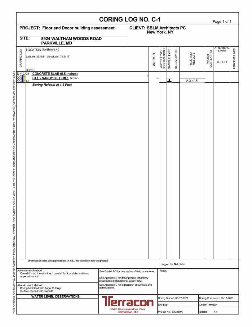
2-3-4/-5"
CONCRETE SLAB (5.5 inches)FILL - SANDY SILT (ML), brown
Boring Refusal at 1.5 Feet
0.5
1.5
Logged By: Nat GalloStratification lines are approximate. In-situ, the transition may be gradual.
TH
IS B
OR
ING
LO
G IS
NO
T V
ALI
D IF
SE
PA
RA
TE
D F
RO
M O
RIG
INA
L R
EP
OR
T. G
EO
SM
AR
T L
OG
-NO
WE
LL L
AB
EY
2150
77
FLO
OR
AN
D D
EC
OR
- R
EC
OV
ER
ED
.GP
J T
ER
RA
CO
N_D
AT
AT
EM
PLA
TE
.GD
T 7
/9/2
1
WA
TE
R L
EV
EL
OB
SE
RV
AT
ION
S
DE
PT
H (
Ft.)
FIE
LD T
ES
TR
ES
ULT
S
RE
CO
VE
RY
(In
.)
8924 WALTHAM WOODS ROAD PARKVILLE, MDSITE:
Page 1 of 1
Advancement Method:Core drill machine with 4 Inch core bit for floor slabs and handauger within soil
Abandonment Method:Boring backfilled with Auger CuttingsSurface capped with concrete
Notes:
Project No.: EY215077
Drill Rig:
Boring Started: 06-17-2021
CORING LOG NO. C-1SBLM Architects PCCLIENT:New York, NY
Driller: Terracon
Boring Completed: 06-17-2021
Exhibit: A-4
See Exhibit A-3 for description of field procedures.
See Appendix B for description of laboratoryprocedures and additional data (if any).
See Appendix C for explanation of symbols andabbreviations.
PROJECT: Floor and Decor building assessment
20401 Seneca Meadows PkwyGermantown, MD
WATER LEVEL OBSERVATIONS
PE
RC
EN
T F
INE
S
WA
TE
RC
ON
TE
NT
(%
)
ATTERBERGLIMITS
LL-PL-PI
LOCATION See Exhibit A-2
Latitude: 39.4031° Longitude: -76.5417°
GR
AP
HIC
LO
G
DEPTH
SA
MP
LE T
YP
E

2-4-4/-5"
CONCRETE SLAB (6 inch)FILL - SANDY SILT WITH GRAVEL (ML), brown
Boring Refusal at 1.5 Feet
0.5
1.5
Logged By: Nat GalloStratification lines are approximate. In-situ, the transition may be gradual.
TH
IS B
OR
ING
LO
G IS
NO
T V
ALI
D IF
SE
PA
RA
TE
D F
RO
M O
RIG
INA
L R
EP
OR
T. G
EO
SM
AR
T L
OG
-NO
WE
LL L
AB
EY
2150
77
FLO
OR
AN
D D
EC
OR
- R
EC
OV
ER
ED
.GP
J T
ER
RA
CO
N_D
AT
AT
EM
PLA
TE
.GD
T 7
/9/2
1
WA
TE
R L
EV
EL
OB
SE
RV
AT
ION
S
DE
PT
H (
Ft.)
FIE
LD T
ES
TR
ES
ULT
S
RE
CO
VE
RY
(In
.)
8924 WALTHAM WOODS ROAD PARKVILLE, MDSITE:
Page 1 of 1
Advancement Method:Core drill machine with 4 Inch core bit for floor slabs and handauger within soil
Abandonment Method:Boring backfilled with Auger CuttingsSurface capped with concrete
Notes:
Project No.: EY215077
Drill Rig:
Boring Started: 06-18-2021
CORING LOG NO. C-2SBLM Architects PCCLIENT:New York, NY
Driller: Terracon
Boring Completed: 06-18-2021
Exhibit: A-5
See Exhibit A-3 for description of field procedures.
See Appendix B for description of laboratoryprocedures and additional data (if any).
See Appendix C for explanation of symbols andabbreviations.
PROJECT: Floor and Decor building assessment
20401 Seneca Meadows PkwyGermantown, MD
WATER LEVEL OBSERVATIONS
PE
RC
EN
T F
INE
S
WA
TE
RC
ON
TE
NT
(%
)
ATTERBERGLIMITS
LL-PL-PI
LOCATION See Exhibit A-2
Latitude: 39.4028° Longitude: -76.5419°
GR
AP
HIC
LO
G
DEPTH
SA
MP
LE T
YP
E

3-4-5/-5"
CONCRETE SLAB (4 inch)FILL - SILTY SAND (SW), brown, moist
Boring Refusal at 1.5 Feet
0.5
1.5
Logged By: Nat GalloStratification lines are approximate. In-situ, the transition may be gradual.
TH
IS B
OR
ING
LO
G IS
NO
T V
ALI
D IF
SE
PA
RA
TE
D F
RO
M O
RIG
INA
L R
EP
OR
T. G
EO
SM
AR
T L
OG
-NO
WE
LL L
AB
EY
2150
77
FLO
OR
AN
D D
EC
OR
- R
EC
OV
ER
ED
.GP
J T
ER
RA
CO
N_D
AT
AT
EM
PLA
TE
.GD
T 7
/9/2
1
WA
TE
R L
EV
EL
OB
SE
RV
AT
ION
S
DE
PT
H (
Ft.)
FIE
LD T
ES
TR
ES
ULT
S
RE
CO
VE
RY
(In
.)
8924 WALTHAM WOODS ROAD PARKVILLE, MDSITE:
Page 1 of 1
Advancement Method:Core drill machine with 4 Inch core bit for floor slabs and handauger within soil
Abandonment Method:Boring backfilled with Auger CuttingsSurface capped with concrete
Notes:
Project No.: EY215077
Drill Rig:
Boring Started: 06-18-2021
CORING LOG NO. C-3SBLM Architects PCCLIENT:New York, NY
Driller: Terracon
Boring Completed: 06-18-2021
Exhibit: A-6
See Exhibit A-3 for description of field procedures.
See Appendix B for description of laboratoryprocedures and additional data (if any).
See Appendix C for explanation of symbols andabbreviations.
PROJECT: Floor and Decor building assessment
20401 Seneca Meadows PkwyGermantown, MD
WATER LEVEL OBSERVATIONS
PE
RC
EN
T F
INE
S
WA
TE
RC
ON
TE
NT
(%
)
ATTERBERGLIMITS
LL-PL-PI
LOCATION See Exhibit A-2
Latitude: 39.4025° Longitude: -76.5414°
GR
AP
HIC
LO
G
DEPTH
SA
MP
LE T
YP
E

12-10-16/-5"
CONCRETE SLAB (5.5 inch)FILL - LEAN CLAY WITH SAND (CL), brown, traces of gravel
Boring Refusal at 1.5 Feet
0.5
1.5
Logged By: Nat GalloStratification lines are approximate. In-situ, the transition may be gradual.
TH
IS B
OR
ING
LO
G IS
NO
T V
ALI
D IF
SE
PA
RA
TE
D F
RO
M O
RIG
INA
L R
EP
OR
T. G
EO
SM
AR
T L
OG
-NO
WE
LL L
AB
EY
2150
77
FLO
OR
AN
D D
EC
OR
- R
EC
OV
ER
ED
.GP
J T
ER
RA
CO
N_D
AT
AT
EM
PLA
TE
.GD
T 7
/9/2
1
WA
TE
R L
EV
EL
OB
SE
RV
AT
ION
S
DE
PT
H (
Ft.)
FIE
LD T
ES
TR
ES
ULT
S
RE
CO
VE
RY
(In
.)
8924 WALTHAM WOODS ROAD PARKVILLE, MDSITE:
Page 1 of 1
Advancement Method:Core drill machine with 4 Inch core bit for floor slabs and handauger within soil
Abandonment Method:Boring backfilled with Auger CuttingsSurface capped with concrete
Notes:
Project No.: EY215077
Drill Rig:
Boring Started: 06-18-2021
CORING LOG NO. C-4SBLM Architects PCCLIENT:New York, NY
Driller: Terracon
Boring Completed: 06-18-2021
Exhibit: A-7
See Exhibit A-3 for description of field procedures.
See Appendix B for description of laboratoryprocedures and additional data (if any).
See Appendix C for explanation of symbols andabbreviations.
PROJECT: Floor and Decor building assessment
20401 Seneca Meadows PkwyGermantown, MD
WATER LEVEL OBSERVATIONS
PE
RC
EN
T F
INE
S
WA
TE
RC
ON
TE
NT
(%
)
ATTERBERGLIMITS
LL-PL-PI
LOCATION See Exhibit A-2
Latitude: 39.4022° Longitude: -76.5417°
GR
AP
HIC
LO
G
DEPTH
SA
MP
LE T
YP
E

5-9-7/-5"
CONCRETE SLAB (3.75 inch), vapor barrier present beneath the slabFILL - SANDY SILT WITH GRAVEL (ML), brown, moist
Boring Refusal at 1.5 Feet
0.5
1.5
Logged By: Nat GalloStratification lines are approximate. In-situ, the transition may be gradual.
TH
IS B
OR
ING
LO
G IS
NO
T V
ALI
D IF
SE
PA
RA
TE
D F
RO
M O
RIG
INA
L R
EP
OR
T. G
EO
SM
AR
T L
OG
-NO
WE
LL L
AB
EY
2150
77
FLO
OR
AN
D D
EC
OR
- R
EC
OV
ER
ED
.GP
J T
ER
RA
CO
N_D
AT
AT
EM
PLA
TE
.GD
T 7
/9/2
1
WA
TE
R L
EV
EL
OB
SE
RV
AT
ION
S
DE
PT
H (
Ft.)
FIE
LD T
ES
TR
ES
ULT
S
RE
CO
VE
RY
(In
.)
8924 WALTHAM WOODS ROAD PARKVILLE, MDSITE:
Page 1 of 1
Advancement Method:Core drill machine with 4 Inch core bit for floor slabs and handauger within soil
Abandonment Method:Boring backfilled with Auger CuttingsSurface capped with concrete
Notes:
Project No.: EY215077
Drill Rig:
Boring Started: 06-18-2021
CORING LOG NO. C-5SBLM Architects PCCLIENT:New York, NY
Driller: Terracon
Boring Completed: 06-18-2021
Exhibit: A-8
See Exhibit A-3 for description of field procedures.
See Appendix B for description of laboratoryprocedures and additional data (if any).
See Appendix C for explanation of symbols andabbreviations.
PROJECT: Floor and Decor building assessment
20401 Seneca Meadows PkwyGermantown, MD
WATER LEVEL OBSERVATIONS
PE
RC
EN
T F
INE
S
WA
TE
RC
ON
TE
NT
(%
)
ATTERBERGLIMITS
LL-PL-PI
LOCATION See Exhibit A-2
Latitude: 39.4028° Longitude: -76.5411°
GR
AP
HIC
LO
G
DEPTH
SA
MP
LE T
YP
E
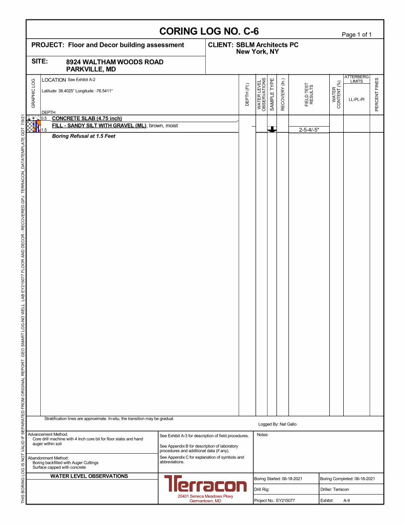
2-5-4/-5"
CONCRETE SLAB (4.75 inch)FILL - SANDY SILT WITH GRAVEL (ML), brown, moist
Boring Refusal at 1.5 Feet
0.5
1.5
Logged By: Nat GalloStratification lines are approximate. In-situ, the transition may be gradual.
TH
IS B
OR
ING
LO
G IS
NO
T V
ALI
D IF
SE
PA
RA
TE
D F
RO
M O
RIG
INA
L R
EP
OR
T. G
EO
SM
AR
T L
OG
-NO
WE
LL L
AB
EY
2150
77
FLO
OR
AN
D D
EC
OR
- R
EC
OV
ER
ED
.GP
J T
ER
RA
CO
N_D
AT
AT
EM
PLA
TE
.GD
T 7
/9/2
1
WA
TE
R L
EV
EL
OB
SE
RV
AT
ION
S
DE
PT
H (
Ft.)
FIE
LD T
ES
TR
ES
ULT
S
RE
CO
VE
RY
(In
.)
8924 WALTHAM WOODS ROAD PARKVILLE, MDSITE:
Page 1 of 1
Advancement Method:Core drill machine with 4 Inch core bit for floor slabs and handauger within soil
Abandonment Method:Boring backfilled with Auger CuttingsSurface capped with concrete
Notes:
Project No.: EY215077
Drill Rig:
Boring Started: 06-18-2021
CORING LOG NO. C-6SBLM Architects PCCLIENT:New York, NY
Driller: Terracon
Boring Completed: 06-18-2021
Exhibit: A-9
See Exhibit A-3 for description of field procedures.
See Appendix B for description of laboratoryprocedures and additional data (if any).
See Appendix C for explanation of symbols andabbreviations.
PROJECT: Floor and Decor building assessment
20401 Seneca Meadows PkwyGermantown, MD
WATER LEVEL OBSERVATIONS
PE
RC
EN
T F
INE
S
WA
TE
RC
ON
TE
NT
(%
)
ATTERBERGLIMITS
LL-PL-PI
LOCATION See Exhibit A-2
Latitude: 38.4025° Longitude: -76.5411°
GR
AP
HIC
LO
G
DEPTH
SA
MP
LE T
YP
E

10-22-16/-5"
CONCRETE SLAB (3.75 inch), vapor barrier present beneath the slabFILL - SANDY SILT WITH GRAVEL (ML), brown
Boring Refusal at 1.5 Feet
0.5
1.5
Logged By: Nat GalloStratification lines are approximate. In-situ, the transition may be gradual.
TH
IS B
OR
ING
LO
G IS
NO
T V
ALI
D IF
SE
PA
RA
TE
D F
RO
M O
RIG
INA
L R
EP
OR
T. G
EO
SM
AR
T L
OG
-NO
WE
LL L
AB
EY
2150
77
FLO
OR
AN
D D
EC
OR
- R
EC
OV
ER
ED
.GP
J T
ER
RA
CO
N_D
AT
AT
EM
PLA
TE
.GD
T 7
/9/2
1
WA
TE
R L
EV
EL
OB
SE
RV
AT
ION
S
DE
PT
H (
Ft.)
FIE
LD T
ES
TR
ES
ULT
S
RE
CO
VE
RY
(In
.)
8924 WALTHAM WOODS ROAD PARKVILLE, MDSITE:
Page 1 of 1
Advancement Method:Core drill machine with 4 Inch core bit for floor slabs and handauger within soil
Abandonment Method:Boring backfilled with Auger CuttingsSurface capped with concrete
Notes:
Project No.: EY215077
Drill Rig:
Boring Started: 06-18-2021
CORING LOG NO. C-7SBLM Architects PCCLIENT:New York, NY
Driller: Terracon
Boring Completed: 06-18-2021
Exhibit: A-10
See Exhibit A-3 for description of field procedures.
See Appendix B for description of laboratoryprocedures and additional data (if any).
See Appendix C for explanation of symbols andabbreviations.
PROJECT: Floor and Decor building assessment
20401 Seneca Meadows PkwyGermantown, MD
WATER LEVEL OBSERVATIONS
PE
RC
EN
T F
INE
S
WA
TE
RC
ON
TE
NT
(%
)
ATTERBERGLIMITS
LL-PL-PI
LOCATION See Exhibit A-2
Latitude: 39.4028° Longitude: -76.5406°
GR
AP
HIC
LO
G
DEPTH
SA
MP
LE T
YP
E

6-11-8/-5"
CONCRETE SLAB (5.5 inch)FILL - SANDY SILT WITH GRAVEL (ML), brown, moist
Boring Refusal at 1.5 Feet
0.5
1.5
Logged By: Nat GalloStratification lines are approximate. In-situ, the transition may be gradual.
TH
IS B
OR
ING
LO
G IS
NO
T V
ALI
D IF
SE
PA
RA
TE
D F
RO
M O
RIG
INA
L R
EP
OR
T. G
EO
SM
AR
T L
OG
-NO
WE
LL L
AB
EY
2150
77
FLO
OR
AN
D D
EC
OR
- R
EC
OV
ER
ED
.GP
J T
ER
RA
CO
N_D
AT
AT
EM
PLA
TE
.GD
T 7
/9/2
1
WA
TE
R L
EV
EL
OB
SE
RV
AT
ION
S
DE
PT
H (
Ft.)
FIE
LD T
ES
TR
ES
ULT
S
RE
CO
VE
RY
(In
.)
8924 WALTHAM WOODS ROAD PARKVILLE, MDSITE:
Page 1 of 1
Advancement Method:Core drill machine with 4 Inch core bit for floor slabs and handauger within soil
Abandonment Method:Boring backfilled with Auger CuttingsSurface capped with concrete
Notes:
Project No.: EY215077
Drill Rig:
Boring Started: 06-18-2021
CORING LOG NO. C-8SBLM Architects PCCLIENT:New York, NY
Driller: Terracon
Boring Completed: 06-18-2021
Exhibit: A-11
See Exhibit A-3 for description of field procedures.
See Appendix B for description of laboratoryprocedures and additional data (if any).
See Appendix C for explanation of symbols andabbreviations.
PROJECT: Floor and Decor building assessment
20401 Seneca Meadows PkwyGermantown, MD
WATER LEVEL OBSERVATIONS
PE
RC
EN
T F
INE
S
WA
TE
RC
ON
TE
NT
(%
)
ATTERBERGLIMITS
LL-PL-PI
LOCATION See Exhibit A-2
Latitude: 39.4031° Longitude: -76.5408°
GR
AP
HIC
LO
G
DEPTH
SA
MP
LE T
YP
E

7-7-7/-5"
CONCRETE SLAB (4.74 inch)FILL - SANDY SILT WITH GRAVEL (ML), brown, moist
Boring Refusal at 1.5 Feet
0.5
1.5
Logged By: Nat GalloStratification lines are approximate. In-situ, the transition may be gradual.
TH
IS B
OR
ING
LO
G IS
NO
T V
ALI
D IF
SE
PA
RA
TE
D F
RO
M O
RIG
INA
L R
EP
OR
T. G
EO
SM
AR
T L
OG
-NO
WE
LL L
AB
EY
2150
77
FLO
OR
AN
D D
EC
OR
- R
EC
OV
ER
ED
.GP
J T
ER
RA
CO
N_D
AT
AT
EM
PLA
TE
.GD
T 7
/9/2
1
WA
TE
R L
EV
EL
OB
SE
RV
AT
ION
S
DE
PT
H (
Ft.)
FIE
LD T
ES
TR
ES
ULT
S
RE
CO
VE
RY
(In
.)
8924 WALTHAM WOODS ROAD PARKVILLE, MDSITE:
Page 1 of 1
Advancement Method:Core drill machine with 4 Inch core bit for floor slabs and handauger within soil
Abandonment Method:Boring backfilled with Auger CuttingsSurface capped with concrete
Notes:
Project No.: EY215077
Drill Rig:
Boring Started: 06-18-2021
CORING LOG NO. C-9SBLM Architects PCCLIENT:New York, NY
Driller: Terracon
Boring Completed: 06-18-2021
Exhibit: A-12
See Exhibit A-3 for description of field procedures.
See Appendix B for description of laboratoryprocedures and additional data (if any).
See Appendix C for explanation of symbols andabbreviations.
PROJECT: Floor and Decor building assessment
20401 Seneca Meadows PkwyGermantown, MD
WATER LEVEL OBSERVATIONS
PE
RC
EN
T F
INE
S
WA
TE
RC
ON
TE
NT
(%
)
ATTERBERGLIMITS
LL-PL-PI
LOCATION See Exhibit A-2
Latitude: 39.4033° Longitude: -76.5408°
GR
AP
HIC
LO
G
DEPTH
SA
MP
LE T
YP
E

0
10
20
30
40
50
60
0 20 40 60 80 100
CH o
r
OH
CL o
r
OL
ML or OL
MH or OH
"U" L
ine
"A" L
ine
ATTERBERG LIMITS RESULTSASTM D4318
PLASTICITY
INDEX
LIQUID LIMIT
PROJECT NUMBER: EY215077PROJECT: Floor and Decor building
investigation
SITE: 8924 WALTHAM WOODS ROAD PARKVILLE, MD
CLIENT: SBLM Architects PC New York, NY
EXHIBIT: B-1
20401 Seneca Meadows PkwyGermantown, MD
LAB
OR
AT
OR
Y T
ES
TS
AR
E N
OT
VA
LID
IF S
EP
AR
AT
ED
FR
OM
OR
IGIN
AL
RE
PO
RT
.
AT
TE
RB
ER
G L
IMIT
S L
AB
EY
2150
77 F
LOO
R A
ND
DE
CO
R.G
PJ
TE
RR
AC
ON
_DA
TA
TE
MP
LAT
E.G
DT
7/1
/21
B-1
B-2
LL
10
21
38
41
48
62
Boring ID Depth
PIPL
18.5 - 20
8.5 - 10
SM
SM
SILTY SAND
SILTY SAND
DescriptionUSCSFines
39.9
34.1
CL-ML

0
5
10
15
20
25
30
35
40
45
50
55
60
65
70
75
80
85
90
95
100
0.0010.010.1110100
3/4 1/23/8 30 403 60
HYDROMETERU.S. SIEVE OPENING IN INCHES
16 20
100
90
80
70
60
50
40
30
20
10
0
U.S. SIEVE NUMBERS
44 10063 2 10 14 506 2001.5 81 140
PE
RC
EN
T F
INE
R B
Y W
EIG
HT
PE
RC
EN
T C
OA
RS
ER
BY
WE
IGH
T
GRAIN SIZE DISTRIBUTIONASTM D422 / ASTM C136
PROJECT NUMBER: EY215077PROJECT: Floor and Decor building
investigation
SITE: 8924 WALTHAM WOODS ROAD PARKVILLE, MD
CLIENT: SBLM Architects PC New York, NY
EXHIBIT: B-1
20401 Seneca Meadows PkwyGermantown, MD
LAB
OR
AT
OR
Y T
ES
TS
AR
E N
OT
VA
LID
IF S
EP
AR
AT
ED
FR
OM
OR
IGIN
AL
RE
PO
RT
.
GR
AIN
SIZ
E: U
SC
S 1
LA
B E
Y21
507
7 F
LOO
R A
ND
DE
CO
R.G
PJ
TE
RR
AC
ON
_DA
TA
TE
MP
LAT
E.G
DT
7/1
/21
D30
% SAND% GRAVEL% COBBLES
COEFFICIENTS
coarse
BORING ID
CU
SOIL DESCRIPTION
REMARKS
GRAIN SIZE
DEPTH
SILT OR CLAYCOBBLESGRAVEL SAND
mediumfine coarse fine
SieveSieveSieve
100.092.5289.080.1370.6362.5854.4744.0834.09
100.099.3692.9883.2871.1856.2339.93
3/4"3/8"#4#10#20#40#60#100#200
% Finer% Finer% Finer
% SILT
CC
D10
B-1
B-2
USCS% CLAY% FINES
D60
SILTY SAND (SM)
SILTY SAND (SM)
#4#10#20#40#60#100#200
39.9
34.1
60.1
54.9
0.0
0.0
18.5 - 20
8.5 - 10
0.0
11.0
SM
SM
0.171 0.359
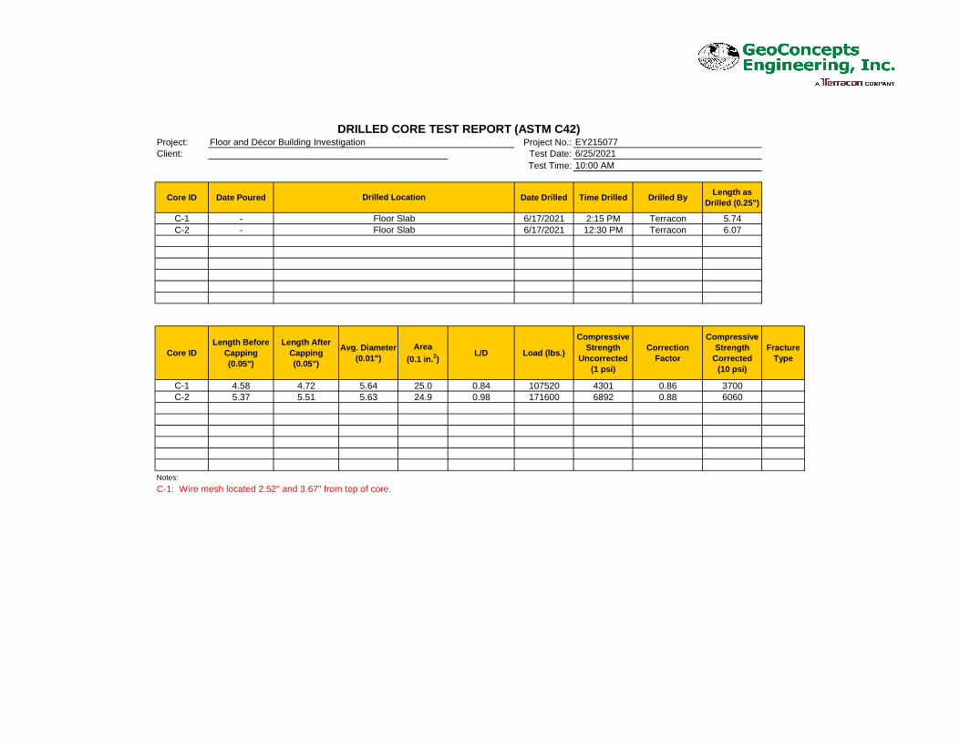
Project: Project No.:Client: Test Date:
Test Time:
Core ID Date Poured Date Drilled Time Drilled Drilled By Length asDrilled (0.25")
C-1 - 6/17/2021 2:15 PM Terracon 5.74C-2 - 6/17/2021 12:30 PM Terracon 6.07
Core IDLength Before
Capping(0.05")
Length AfterCapping(0.05")
Avg. Diameter(0.01")
Area(0.1 in.2)
L/D Load (lbs.)
CompressiveStrength
Uncorrected(1 psi)
CorrectionFactor
CompressiveStrength
Corrected(10 psi)
FractureType
C-1 4.58 4.72 5.64 25.0 0.84 107520 4301 0.86 3700C-2 5.37 5.51 5.63 24.9 0.98 171600 6892 0.88 6060
Notes:
DRILLED CORE TEST REPORT (ASTM C42)Floor and Décor Building Investigation EY215077
6/25/2021
C-1: Wire mesh located 2.52" and 3.67" from top of core.
10:00 AM
Drilled Location
Floor SlabFloor Slab