geotechnical engineering report - pavilion construction roosevelt/spec... · geotechnical...
TRANSCRIPT

Geotechnical Engineering Report 6800 Roosevelt Project
Seattle, Washington
March 12, 2015
Terracon Project No. 81155015
Prepared for:
Emerald Bay Equity
Seattle, Washington
Prepared by:
Terracon Consultants, Inc.
Mountlake Terrace, Washington


TABLE OF CONTENTS
Responsive ■ Resourceful ■ Reliable
Page
EXECUTIVE SUMMARY ............................................................................................................. i
1.0 INTRODUCTION ............................................................................................................. 1
2.0 PROJECT INFORMATION ............................................................................................. 1
2.1 Project Description ............................................................................................... 1
2.2 Site Location and Description .............................................................................. 2
3.0 SUBSURFACE CONDITIONS ........................................................................................ 2
3.1 Previous Studies .................................................................................................. 2
3.2 Geology ............................................................................................................... 2
3.3 Subsurface Soil Conditions .................................................................................. 3
3.4 Groundwater ........................................................................................................ 3
4.0 RECOMMENDATIONS FOR DESIGN AND CONSTRUCTION ...................................... 5
4.1 Geotechnical Considerations ............................................................................... 5
4.2 Earthwork ............................................................................................................ 5
4.2.1 Site Preparation ........................................................................................ 5
4.2.2 Structural Fill ............................................................................................ 6
4.2.3 Compaction Requirements ....................................................................... 7
4.2.4 Utility Trenches......................................................................................... 7
4.2.5 Earthwork Construction Consideration ..................................................... 8
4.2.6 Wet Weather / Subgrade Stabilization ...................................................... 8
4.3 Seismic Considerations........................................................................................ 8
4.4 Foundations ......................................................................................................... 9
4.4.1 Shallow Foundation Design Recommendations........................................ 9
4.4.2 Foundation Construction Considerations ................................................ 11
4.5 Lateral Pressures on Permanent Basement Walls ............................................. 11
4.6 Slab-on-Grade ................................................................................................... 12
4.6.1 Slab-on-Grade Design Recommendations ............................................. 12
4.6.2 Slab-on-Grade Construction Considerations .......................................... 13
4.7 Subsurface Drainage Provisions ........................................................................ 13
4.7.1 Wall Drainage ......................................................................................... 13
4.7.2 Footing Drains ........................................................................................ 13
4.7.3 Slab Underdrains .................................................................................... 14
4.7.4 Sumps .................................................................................................... 14
4.8 Shoring .............................................................................................................. 14
4.8.1 Soil Nail Wall Design Recommendations ................................................ 14
4.8.2 Soil Nail Shoring Installation ................................................................... 16
4.8.3 Soldier Piles ........................................................................................... 16
4.8.4 Soldier Pile Shoring Installation .............................................................. 18
4.8.5 Monitoring of Temporary Shoring ........................................................... 18
4.9 Construction Dewatering .................................................................................... 19
5.0 GENERAL COMMENTS ................................................................................................ 19

TABLE OF CONTENTS (continued)
Responsive ■ Resourceful ■ Reliable
APPENDIX A – SELECT FIELD EXPLORATION LOGS FROM PREVIOUS STUDY
Exhibit A-1 Site Location
Exhibit A-2 Exploration Plan
Exhibit A-3 Field Exploration Description
Exhibit A-4 to A-20 Boring Logs
APPENDIX B – SUPPORTING DOCUMENTS
Exhibit B-1 General Notes
Exhibit B-2 Unified Soil Classification System

Geotechnical Engineering Report 6800 Roosevelt Project ■ Seattle, Washington March 12, 2015 ■ Terracon Project No. 81155015
Responsive ■ Resourceful ■ Reliable i
EXECUTIVE SUMMARY
A geotechnical study has been completed for the design of the proposed residential
development located at 6800 Roosevelt Way NE, Seattle, Washington. Seventeen (17) borings,
completed for a previous environmental study by Terracon, to depths of approximately 13 feet to
30 feet below the existing ground surface within the project site were used as the basis to
develop geotechnical design recommendations. Based on the information obtained from our
previous subsurface exploration, the site is suitable for development of the proposed project.
The geotechnical considerations identified include the following:
Soils and Groundwater: Soils at the site generally consisted of silty sand with variable
gravel content in a medium dense to very dense condition (i.e., fill over glacial till).
Groundwater was observed at the time of exploration in several explorations, we believe
that this water is perched water above the glacial till and within more permeable zones
within the glacial till soils.
Foundations: Shallow foundations will provide adequate support for the proposed
building provided that the foundation subgrades are properly prepared.
Seismic Design Considerations: Per the 2012 International Building Code (IBC), the
seismic site classification for this site is C.
Subsurface Drainage: A full face geocomposite drainage mat discharging to a
perimeter footing drain system combined with below slab underdrain is recommended to
provide subsurface drainage of the below grade floor levels.
Excavation Shoring: Conventional soldier piles with tieback anchors/internal bracing,
soil nailing, or composite soil nailing shoring systems appear feasible from a
geotechnical standpoint to support excavation required to construct the below grade
portions of the building.
Close monitoring of the construction operations discussed herein will be critical in achieving the
design subgrade support. We therefore recommend that Terracon be retained to monitor this
portion of the work.
This summary should be used in conjunction with the entire report for design purposes. It
should be recognized that details were not included or fully developed in this section, and the
report must be read in its entirety for a comprehensive understanding of the items contained
herein. The section titled GENERAL COMMENTS should be read for an understanding of the
report limitations.

Responsive ■ Resourceful ■ Reliable 1
GEOTECHNICAL ENGINEERING REPORT
6800 Roosevelt Way NE
Seattle, Washington Terracon Project No. 81155015
March 12, 2015
1.0 INTRODUCTION
This geotechnical engineering report has been completed for the design of a proposed mixed-
use residential development located at 6800 Roosevelt Way NE, Seattle. Seventeen (17)
borings were completed to depths ranging from approximately 13 feet to 30 feet below the
existing ground surface within the project site for a previous environmental study by Terracon.
Logs of these borings along with an Exploration Plan are included in Appendix A of this report.
The purpose of these services is to provide information and geotechnical engineering
recommendations relative to:
soil conditions foundation design and construction
groundwater conditions site preparation and earthwork
permanent drainage provisions seismic considerations
lateral earth pressures shoring considerations
The project description, site conditions and our geotechnical conclusions and design
recommendations are presented in the text of this report. Supporting data including field
exploration procedures and detailed exploration logs are presented as appendices. No
geotechnical laboratory testing was conducted as part of this study as the soil samples from the
previous environmental study were not available.
2.0 PROJECT INFORMATION
2.1 Project Description
Item Description
Proposed structure Five story structure with one to two levels of below grade parking.
Ground Floor Elevation
Based on architectural drawings provided by the client, the
proposed finished floor elevation ranges from 250 feet along the
north edge of the building to 244 feet along the south edge of the
building
Below grade areas One to two levels of parking garage

Geotechnical Engineering Report 6800 Roosevelt Project ■ Seattle, Washington March 12, 2015 ■ Terracon Project No. 81155015
Responsive ■ Resourceful ■ Reliable 2
Item Description
Excavation Shoring Heights
Assuming 2 feet of excavation below the finish floor slab elevation
for footings, excavation shoring heights range from about 29 feet in
the southeast corner to about 16 feet in the northwest corner.
2.2 Site Location and Description
Item Description
Location Vicinity of 6800 Roosevelt Way NE, Seattle Washington
Existing improvements
Several single story masonry buildings in the north half of the site,
and a single story masonry building and adjoined paved pay
parking lot in the south side.
Current ground cover Asphalt and concrete paving and landscaping
Existing topography
Moderately sloping site (approximately 5% grade) from the high
point in the northeast corner (elevation 254) to the low point in the
southeast corner (elevation 244).
3.0 SUBSURFACE CONDITIONS
3.1 Previous Studies
Terracon completed a Phase II Environmental Assessment of this site in 2014. As part of this
assessment, seventeen (17) borings were advanced to depths ranging from 13 feet to 30 feet
below the existing ground surface within the site at the time of exploration. Sufficient data was
collected from these explorations to form our basis for geotechnical conclusions and design
recommendations. A description of our field exploration procedures and logs of the exploratory
borings from the previous study are presented in Appendix A.
3.2 Geology
The Seattle area is generally underlain by a glacial sequence of soil consisting of recessional
outwash, glacial till, advance outwash, and lacustrine deposits associated with the Vashon
Stade glaciation. Also present are older glacial and interglacial deposits. The following
geologic map was reviewed as part of our study:
“Geologic Map of Northeastern Seattle (Part of the Seattle North 7.5’x15’ Quadrangle),
King County”, by Kathy G. Troost, and others, USGS, published 2009.

Geotechnical Engineering Report 6800 Roosevelt Project ■ Seattle, Washington March 12, 2015 ■ Terracon Project No. 81155015
Responsive ■ Resourceful ■ Reliable 3
Based on the geologic map, the site is underlain by Qvt which is identified as deposits of Vashon
age till. These deposits consist of a dense to very dense mixture of gravel, sand, silt and clay,
with some cobble and trace boulders. The subsurface conditions encountered in the exploration
program conducted for our previous environmental study encountered soils consistent with the
geologic map.
The geologic map also shows the contact between till and deposits identified as Vashon age
advance outwash is approximately at 68th Street on the south side of the site. Although our
explorations did not encounter soils consistent with this unit, excavation on the south side of the
site may encounter the advance outwash soils.
3.3 Subsurface Soil Conditions
The 17 borings used for this evaluation extended to depths ranging from approximately 13 feet
to 30 feet below the existing ground surface within the project site. Soil descriptions presented in
this report are based on the subsurface conditions encountered at specific exploration locations
across the site. Variations in subsurface conditions may exist between the exploration
locations. Refer to the boring logs in Appendix A for a detailed description of the subsurface
conditions encountered at the locations of the explorations completed for this project.
Stratification boundaries on the logs represent the approximate locations of changes in soil
types; in-situ, the transition between materials may be gradual. Based on our borings, a
generalized description of the site soil conditions is presented below.
Stratum
Approximate Depth to
Bottom of Stratum
(feet)
Material Description Consistency/
Density
1 0.2 Asphalt/Topsoil N/A
2 0.2 to 12
Sand with variable silt and gravel (Probable
fill over weathered Glacial Till) Loose to dense
3 All borings terminated in
this unit. Silty sand with gravel (Glacial Till) Very dense
Fill/weathered glacial till was encountered to 8 feet in explorations MW-2N, B-1N, B-6S, and
MW-3S, and to 12 feet in explorations MW-1N and B-7S. No fill or weathered till was observed
overlying the glacial till in the other eight borings. We suspect that some of the upper soils in
the borings probably represents fill. However, because the gradation and appearance of the fill
and weathered glacial till are similar, it is difficult to distinguish between these soils in the
borings.
3.4 Groundwater

Geotechnical Engineering Report 6800 Roosevelt Project ■ Seattle, Washington March 12, 2015 ■ Terracon Project No. 81155015
Responsive ■ Resourceful ■ Reliable 4
Groundwater was observed in eight of the borings at the time of exploration. Locations where
groundwater was encountered are distributed across the site north to south and interspersed
among boring locations where water was not encountered during exploration. Based on the soil
observed, the mapped geology, and these observations, we believe that groundwater
encountered was perched above the relatively impermeable glacial till and within localized
sandy zones within the glacial till.
Boring
Approximate Depth to
Groundwater at the Time of
Exploration (feet)
MW-2N 16
B-4N/MW-3N 17
B-8N/MW-4N 15
MW-1N 14
B-1N 13
B-5S 15
MW-1S 15
MW-2S 15
Seven of the 17 explorations had stand pipe piezometers installed to serve as monitoring wells.
A Terracon representative sounded these wells on March 5, 2015. Observed ground water
levels are presented below. Compared to groundwater levels at the time of exploration,
groundwater tables appear to be depressed.
Monitoring
Well
Approximate Depth to
Groundwater on March 5,
2015 (feet)
MW-1S DRY
MW-2S DRY
MW-3S DRY
MW-3N 23
MW-2N 23
MW-4N 22
MW-1N 21
Sound Transit is constructing their Roosevelt Station just one block (approximately 350 feet) to
the south. Njoloma et al. (2012) presented a summary of the North Link Project which indicated
that the regional aquifer is 30 to 65 feet below ground surface in the construction limits of the

Geotechnical Engineering Report 6800 Roosevelt Project ■ Seattle, Washington March 12, 2015 ■ Terracon Project No. 81155015
Responsive ■ Resourceful ■ Reliable 5
station, and that dewatering to depress groundwater below base of excavation at elevation 140
feet (100 feet below ground surface at 67th Street) will be required. It is probable that temporary
dewatering of the Roosevelt Station site is presently influencing the groundwater levels at the
6800 Roosevelt site.
Groundwater conditions are also anticipated to fluctuate, depending on time of year,
precipitation, and site use.
4.0 RECOMMENDATIONS FOR DESIGN AND CONSTRUCTION
4.1 Geotechnical Considerations
Based on our subsurface exploration program from our previous study and associated research,
we conclude that the proposed development is feasible from a geotechnical standpoint,
contingent on proper design and construction practices. Primary geotechnical considerations
are discussed in the following paragraphs.
Foundation support with shallow spread footings is feasible on the glacial till or properly
placed structural fill over a suitably prepared subgrade consisting of native undisturbed soils.
The soils are suitable for shoring consisting of soil nailing or conventional solder piles with
tieback anchors or internal bracing.
The site soils are silty and prone to disturbance in wet site conditions.
Specific conclusions and recommendations regarding these geotechnical considerations, as
well as other geotechnical aspects of design and construction of foundation systems and other
earthwork related phases of the project are outlined in the following sections. The
recommendations contained in this report are based upon the results of field testing (which are
presented in Appendix A), engineering analyses, and our current understanding of the proposed
project. ASTM and Washington State Department of Transportation (WSDOT) specification
codes cited herein respectively refer to the current manual published by the American Society
for Testing & Materials and the current edition of the Standard Specifications for Road, Bridge,
and Municipal Construction, (M41-12).
4.2 Earthwork
4.2.1 Site Preparation
Preparation for site grading and construction should begin with procedures intended to control
surface water runoff and off-site erosion.

Geotechnical Engineering Report 6800 Roosevelt Project ■ Seattle, Washington March 12, 2015 ■ Terracon Project No. 81155015
Responsive ■ Resourceful ■ Reliable 6
Existing improvements within the project site (e.g., pavements, concrete flat work, foundations,
utilities, etc.) should be removed or relocated, as necessary, in accordance with all local, state,
and federal regulations. We have assumed that all existing site fill will be removed in areas to
receive structural fill.
4.2.2 Structural Fill
All fill material placed beneath and adjacent to the building should be placed in accordance with
the recommendations herein for structural fill. Structural fill is not allowed under foundation
elements unless they are designed for the appropriate bearing pressure. Prior to placement,
surfaces to receive structural fill should be in a firm and non-yielding condition and the existing
fill layer at the site should have been removed. All structural fill should be free of organic
material, debris, and other deleterious material. Individual particle size should be less than 4
inches in maximum dimension.
The suitability of soils for use as structural fill is dependent on the gradation and moisture
content of the soil when it is placed. As the amount of fines (that soil fraction passing the U.S.
No. 200 sieve) increases, soil becomes increasingly sensitive to small changes in moisture
content and adequate compaction becomes more difficult, or impossible, to achieve. Generally,
soils containing more than about 5 percent fines by weight (based on that soil fraction passing
the U.S. No. 4 sieve) cannot be compacted to a firm, non-yielding condition when the moisture
content is more than a few percent from optimum. The optimum moisture content yields the
greatest soil density under a given compactive effort.
In general, the site soils consist of silty sand with gravel. These soils are considered generally
acceptable for re-use as structural fill from a compositional perspective; however, these soils
are moisture sensitive and should only be placed during dry periods of weather. After
excavation, we recommend that soil stockpiles be covered with plastic sheeting to maintain their
native moisture content. Should it be desired to reuse onsite soil for structural fill, we
recommend that moisture-density relationship be established through laboratory (Proctor)
testing prior to placement of fill.
Import soils for use as structural fill within and adjacent to the proposed building should consist
of “common” or “select” granular material, depending on the weather conditions at the time of
placement and the anticipated weather conditions until the fill is protected. These materials are
defined below:
Select Fill - “Select” granular fill is recommended for use in wet weather conditions. Select
fill should meet the general requirements of Section 9-03.14(1), Gravel Borrow, as
presented in the Washington State Department of Transportation (WSDOT) Standard
Specifications for Road, Bridge, and Municipal Construction. The percent passing the US
No. 200 mesh sieve should, however, be modified from the WSDOT specification to a

Geotechnical Engineering Report 6800 Roosevelt Project ■ Seattle, Washington March 12, 2015 ■ Terracon Project No. 81155015
Responsive ■ Resourceful ■ Reliable 7
maximum of 5 percent by weight passing the US No. 200 mesh sieve. Select fill can
generally be placed and compacted in a wider variety of weather conditions than Common
import fill.
Common Fill - “Common” fill generally consists of lesser quality, more moisture-sensitive
soils that can be compacted to a firm and non-yielding condition if near the optimum
moisture content. “Common” engineered fill should meet the requirements of Section 9-
03.14(3), Common Borrow, as presented in the WSDOT Standard Specifications for Road,
Bridge, and Municipal Construction.
The use of other fill types should be reviewed and approved by the engineer. Structural fill
should be placed and compacted in horizontal lifts, using equipment and procedures that will
produce recommended moisture content and densities throughout the fill.
4.2.3 Compaction Requirements
If heavy compaction equipment is utilized (e.g., hoe-pack, or vibro-roller), structural fill should be
placed in lifts no greater than 12 inches in loose thickness and compacted to a firm and non-
yielding condition. Thinner lifts may be required if lighter, hand-operated equipment is used.
Each lift should be compacted to at least 95 percent of the modified Proctor (ASTM D 1557)
maximum dry density. This recommended level of compaction should be reduced to 90 to 92
percent of the maximum dry density for subgrade wall backfill and utility trenches below a depth
of 2 feet. Moisture contents within 2 percent of the optimum moisture content will likely be
required to achieve the recommended relative compaction.
4.2.4 Utility Trenches
Utility trenching should conform to all applicable federal, state, and local regulations, such as
OSHA and WISHA, for open excavations.
All trenches should be wide enough to allow for compaction around the haunches of the pipe, or
material such as pea gravel (provided this is allowed by the pipe manufacturer) should be used
below the spring line of the pipes to eliminate the need for mechanical compaction in this portion
of the trenches. We recommend that utility trench excavations be completed using a smooth
excavation bucket (without teeth) to reduce the potential for subgrade disturbance. If water is
encountered in the excavations, it should be removed prior to fill placement.
Materials, placement and compaction of utility trench backfill should be in accordance with the
recommendations presented in Sections 4.2.2 and 4.2.3 of this report. In our opinion, the initial
lift thickness should not exceed one foot unless recommended by the manufacturer to protect
utilities from damage by compacting equipment. Light, hand-operated compaction equipment in
conjunction with thinner fill lift thicknesses may be utilized on backfill placed above utilities if
damage resulting from heavier compaction equipment is of concern.

Geotechnical Engineering Report 6800 Roosevelt Project ■ Seattle, Washington March 12, 2015 ■ Terracon Project No. 81155015
Responsive ■ Resourceful ■ Reliable 8
4.2.5 Earthwork Construction Consideration
It is anticipated that excavations for the proposed construction can be accomplished with
conventional, heavy-duty, earthmoving equipment. The earthwork and shoring contractors
should anticipate very dense soil conditions and the possibility of encountering cobbles and
boulders.
If earthwork takes place during freezing conditions, we recommend that the exposed subgrade
be allowed to thaw and be re-compacted prior to placing subsequent lifts of structural fill.
Alternatively, the frozen soil could be scraped off and wasted to expose unfrozen soil.
The contractor is responsible for designing and constructing stable, temporary excavations as
required to maintain stability of both the excavation sides and bottom. Excavations should be
sloped or shored in the interest of safety, following local and federal regulations, including
current OSHA excavation and trench safety standards.
4.2.6 Wet Weather / Subgrade Stabilization
We recommend that the earthwork portion of this project be completed during extended periods
of dry weather if possible. If earthwork is completed during the wet season, it may be necessary
to take extra precautionary measures to protect subgrade soils. Wet season earthwork may
require additional mitigating measures beyond that which would be expected during the drier
months. Once subgrades are established, it may be necessary to protect the exposed
subgrade soils from construction traffic. Placing quarry spalls or clean pit-run sand and gravel
over these areas would further protect the soils from construction traffic. Exposed footing
subgrades may require placement of a lean concrete mud mat to protect the bearing surface
after excavation.
4.3 Seismic Considerations
We understand the site will be designed to conform to the 2012 International Building Code
(IBC) which is based on designing for an event with a 2 percent chance of exceedance in 50
years. The following discusses the soil site class and seismic hazard potential at the site:
DESCRIPTION VALUE
2012 International Building Code Site
Classification (IBC) 1, 2
C
Site Latitude 47.67828° N
Site Longitude 122.31689° W
Ss Spectral Acceleration for a Short Period for
Site Class B 1.275g
S1 Spectral Acceleration for a 1-Second Period
for Site Class B 0.495g
Geotechnical Engineering Report 6800 Roosevelt Project ■ Seattle, Washington March 12, 2015 ■ Terracon Project No. 81155015
Responsive ■ Resourceful ■ Reliable 9
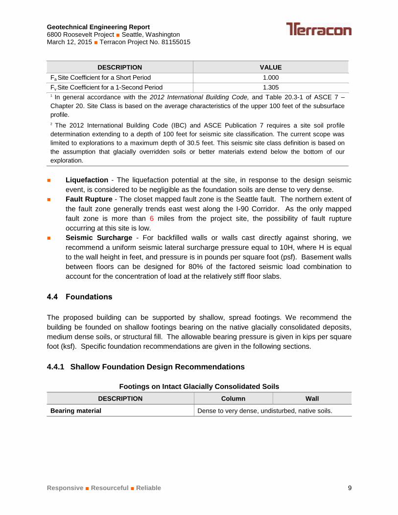
DESCRIPTION VALUE
Fa Site Coefficient for a Short Period
1.000
Fv Site Coefficient for a 1-Second Period
1.305 1 In general accordance with the 2012 International Building Code, and Table 20.3-1 of ASCE 7 –
Chapter 20. Site Class is based on the average characteristics of the upper 100 feet of the subsurface
profile.
2 The 2012 International Building Code (IBC) and ASCE Publication 7 requires a site soil profile
determination extending to a depth of 100 feet for seismic site classification. The current scope was
limited to explorations to a maximum depth of 30.5 feet. This seismic site class definition is based on
the assumption that glacially overridden soils or better materials extend below the bottom of our
exploration.
Liquefaction - The liquefaction potential at the site, in response to the design seismic
event, is considered to be negligible as the foundation soils are dense to very dense.
Fault Rupture - The closet mapped fault zone is the Seattle fault. The northern extent of
the fault zone generally trends east west along the I-90 Corridor. As the only mapped
fault zone is more than 6 miles from the project site, the possibility of fault rupture
occurring at this site is low.
Seismic Surcharge - For backfilled walls or walls cast directly against shoring, we
recommend a uniform seismic lateral surcharge pressure equal to 10H, where H is equal
to the wall height in feet, and pressure is in pounds per square foot (psf). Basement walls
between floors can be designed for 80% of the factored seismic load combination to
account for the concentration of load at the relatively stiff floor slabs.
4.4 Foundations
The proposed building can be supported by shallow, spread footings. We recommend the
building be founded on shallow footings bearing on the native glacially consolidated deposits,
medium dense soils, or structural fill. The allowable bearing pressure is given in kips per square
foot (ksf). Specific foundation recommendations are given in the following sections.
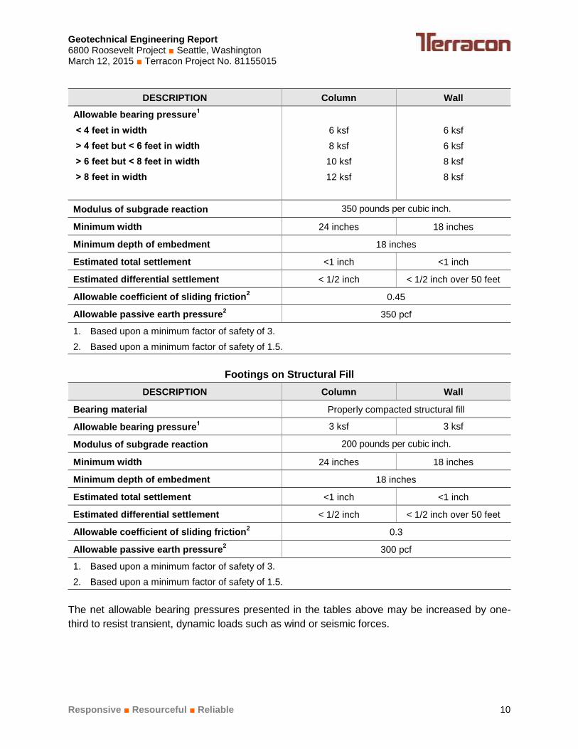
4.4.1 Shallow Foundation Design Recommendations
Footings on Intact Glacially Consolidated Soils
DESCRIPTION Column Wall
Bearing material Dense to very dense, undisturbed, native soils.
Geotechnical Engineering Report 6800 Roosevelt Project ■ Seattle, Washington March 12, 2015 ■ Terracon Project No. 81155015
Responsive ■ Resourceful ■ Reliable 10
DESCRIPTION Column Wall
Allowable bearing pressure1
< 4 feet in width
> 4 feet but < 6 feet in width
> 6 feet but < 8 feet in width
> 8 feet in width
6 ksf
8 ksf
10 ksf
12 ksf
6 ksf
6 ksf
8 ksf
8 ksf
Modulus of subgrade reaction 350 pounds per cubic inch.
Minimum width 24 inches 18 inches
Minimum depth of embedment 18 inches
Estimated total settlement <1 inch <1 inch
Estimated differential settlement < 1/2 inch < 1/2 inch over 50 feet
Allowable coefficient of sliding friction2
0.45
Allowable passive earth pressure2
350 pcf
1. Based upon a minimum factor of safety of 3.
2. Based upon a minimum factor of safety of 1.5.
Footings on Structural Fill
DESCRIPTION Column Wall
Bearing material Properly compacted structural fill
Allowable bearing pressure1 3 ksf 3 ksf
Modulus of subgrade reaction 200 pounds per cubic inch.
Minimum width 24 inches 18 inches
Minimum depth of embedment 18 inches
Estimated total settlement <1 inch <1 inch
Estimated differential settlement < 1/2 inch < 1/2 inch over 50 feet
Allowable coefficient of sliding friction2
0.3
Allowable passive earth pressure2
300 pcf
1. Based upon a minimum factor of safety of 3.
2. Based upon a minimum factor of safety of 1.5.
The net allowable bearing pressures presented in the tables above may be increased by one-
third to resist transient, dynamic loads such as wind or seismic forces.

Geotechnical Engineering Report 6800 Roosevelt Project ■ Seattle, Washington March 12, 2015 ■ Terracon Project No. 81155015
Responsive ■ Resourceful ■ Reliable 11
4.4.2 Foundation Construction Considerations
The base of all foundation excavations should be free of water and loose soil prior to placing
concrete. Concrete should be placed soon after excavating to reduce bearing soil disturbance.
Should the soils at bearing level become excessively dry, disturbed, saturated, or frozen, the
affected soil should be removed prior to placing concrete. This includes disturbance during
placement of reinforcing steel. We recommend that Terracon be retained to observe foundation
subgrades.
4.5 Lateral Pressures on Permanent Basement Walls
We recommend that permanent basement walls constructed flush against shoring be designed
to withstand uniform rectangular lateral pressure equal to 22 H, in psf, where H equals the wall
height in feet. Permanent walls should be provided with drainage as described subsequently in
this report.
Backfilled walls, not constructed flush against the shoring, can be designed for conventional soil
loading. The lateral soil pressures on the subgrade or foundation walls backfilled on one side
only will primarily depend on the degree of compaction and amount of lateral movement
permitted at the top of the wall during backfilling operations. If walls are free to yield at the top
an amount equal to approximately 0.001 times the height of the wall, then the soil pressure will
be less than if the movement is more limited by stiffness or by construction of the structural floor
network prior to backfilling. We recommend that equivalent fluid pressures of 35 pcf and 55 pcf
be used for yielding and non-yielding backfilled walls, respectively.
A surcharge load should be added to the lateral pressure, if traffic or other loading is anticipated
within a zone extending back from the wall a distance equal to the wall height. A vertical
surcharge equal to 250 psf is recommended for typical traffic loading, which corresponds to a
uniform horizontal pressure equal to 75 psf. A seismic surcharge, as discussed in Section 4.3
should also be considered in the design. For other loads adjacent to the basement wall, such
as adjacent building foundations, please, contact Terracon to estimate appropriate surcharge
pressures.
These equivalent fluid pressures are based on the assumption of a uniform backfill and no
buildup of hydrostatic pressures behind the wall. To prevent the buildup of lateral earth
pressures in excess of the above designed pressures, over compaction of fill behind the walls
should be avoided. This can be accomplished by placing the backfill within 24 inches of the wall
in lifts not exceeding 8 inches in loose depth and compacting with hand-operated or self-
propelled equipment.

Geotechnical Engineering Report 6800 Roosevelt Project ■ Seattle, Washington March 12, 2015 ■ Terracon Project No. 81155015
Responsive ■ Resourceful ■ Reliable 12
Care should be taken where utilities penetrate through basement walls. Minor settlement of the
backfill can put significant soil loading on utilities, and some form of flexible connection may be
appropriate at backfilled wall penetrations.
Wall drainage should be provided per section 4.7 of this report.
4.6 Slab-on-Grade
Floor slabs for the building should be supported on a capillary break layer placed on competent
native soils or structural fill. Under slab drainage should be provided per section 4.7 of this
report.
4.6.1 Slab-on-Grade Design Recommendations
ITEM DESCRIPTION
Slab on grade support1 Minimum 4 inches of capillary break
2
Modulus of subgrade reaction 200 pounds per square inch per inch (psi/in) for
point loading conditions.
1. Upon completion of excavation to subgrade, the subgrade soil moisture content and density
should be maintained until construction of the building floor slabs.
2. Clean crushed rock used for support of floor slabs should meet the general requirements shown in
the Table below. The crushed rock should meet WSDOT durability requirements per their
standard specifications.
Gradation Requirements for Capillary Break
Sieve Size or Diameter Percent Passing
1.5 inch 100 percent
No. 4 0 to 70 percent
No. 10 0 to 30 percent
No. 100 0 to 5 percent
No. 200 0 to 3 percent
Where appropriate, saw-cut control joints should be placed in the slab to help control the
location and extent of cracking. For additional recommendations refer to the ACI Design
Manual. Joints or any cracks that develop should be sealed with a water-proof, non-extruding
compressible compound specifically recommended by the manufacturer for use in heavy-duty
concrete pavement and wet environments.
The use of a vapor retarder should be considered beneath concrete slabs on grade that will be
covered with wood, tile, carpet, or other moisture sensitive or impervious coverings, or when the
slab will support equipment sensitive to moisture. When conditions warrant the use of a vapor

Geotechnical Engineering Report 6800 Roosevelt Project ■ Seattle, Washington March 12, 2015 ■ Terracon Project No. 81155015
Responsive ■ Resourceful ■ Reliable 13
retarder, the slab designer and slab contractor should refer to ACI 302 and ACI 360 for
procedures and cautions regarding the use and placement of a vapor retarder.
4.6.2 Slab-on-Grade Construction Considerations
After excavation to subgrade elevation, the base of the excavation is frequently disturbed or
altered due to utility excavations, construction traffic, desiccation, or rainfall. As a result, the
slab-on-grade subgrade may become unsuitable for floor slab support. At the time of capillary
break placement, the subgrade should be evaluated by proof rolling to verify a firm and non-
yielding surface. Proof rolling should be completed using heavy equipment under the
observation of Terracon. This observer will assess the subgrade conditions prior to capillary
break placement. Areas where loose, soft, or disturbed surface soils are observed should be
compacted or removed and replaced to the depth of the disturbance as recommended for
structural fill.
4.7 Subsurface Drainage Provisions
We recommend that the walls and parking garage slab are positively drained to collect and
convey ground water seepage that may be present. The drainage system should consist of a
combination of freely-draining structural fill, wall drainage, footing drains, under slab drains, and
a sump collection system if discharge by gravity is not possible.
4.7.1 Wall Drainage
Basement walls poured flush against the shoring should be provided with drainage by placing
full face geocomposite drain against the shoring wall. The geocomposite drain should be tied
into the footing drainage system. It is important to provide a good connection between the wall
drain and the footing drainage system. The detail of the wall/footing drain connection will
depend on the type of shoring, basement wall type, and perimeter footing. Drainage behind
walls cast in open excavations can consist of geocomposite drainage as discussed above or a
minimum of a 2-foot wide zone of clean sand and gravel fill with less than 5 percent passing the
No. 200 sieve. If a moisture-free wall is desired, a water proof barrier, such as plastic or
bentonite panels, should be placed over the geocomposite drain prior to pouring or shotcreting
the concrete wall.
4.7.2 Footing Drains
A perimeter footing drain should also be provided and consist of a minimum 4-inch diameter
heavy walled perforated PVC pipe or equivalent. We recommend that the footing drains have a
minimum slope of 0.5 percent, and that the pipe invert is at least 12-inches below the finish floor
slab. The pipe should be bedded in at least 4-inches and surrounded by at least 6-inches, of
drainage material consisting of ¾-inch washed drain rock. We recommend use of nonwoven
filter fabric (Mirafi 140N or equivalent) to wrap the entire pipe and rock assembly. Cleanouts are
recommended for the footing drain system.

Geotechnical Engineering Report 6800 Roosevelt Project ■ Seattle, Washington March 12, 2015 ■ Terracon Project No. 81155015
Responsive ■ Resourceful ■ Reliable 14
4.7.3 Slab Underdrains
A drainage system should be provided below the floor slab. We recommend the floor slab be
underlain by cross drains consisting of 4-inch perforated pipe placed at about 30-foot centers.
We recommend that the slab under drains have a minimum slope of 0.5 percent, and that the
pipe invert is at least 12-inches below the finish floor slab. . The pipe should be bedded in at
least 4-inches and surrounded by at least 6-inches, of drainage material consisting of ¾-inch
washed drain rock. In addition, the entire slab should be underlain by a minimum 4-inch
continuous drainage blanket of clean, free draining, sand and gravel. As discussed in Section
4.6, the capillary break layer may also function as this drainage layer. We recommend use of
nonwoven filter fabric (Mirafi 140N or equivalent) to wrap the entire pipe and gravel assembly.
4.7.4 Sumps
If gravity flow is not possible, the below slab and wall drainage system should drain to a sump
for pumping. The steady state or long term ground water flow rate should be evaluated during
construction and the permanent drainage system sized for that flow. For estimating purposes
and minimum design criteria, a steady state flow rate of 5 gallons per minute (gpm) can be
used. The design flow number should be verified once the excavation is completed. This can
be accomplished by measuring the flow of the temporary dewatering system. If a sump system
is used, a backup pump with emergency power is recommended in case of mechanical
breakdown. We recommend that the sump and drain pipe clean outs be vented to the
atmosphere to prevent the buildup of hydrostatic pressure below the floor slab in case of
mechanical or electrical failure of the sump pumps.
4.8 Shoring
Based on the soil conditions observed at the exploration locations and the proposed floor slab
elevation, we recommend that either soldier pile or soil nail shoring be considered to support the
excavation during construction. The shoring required to support the excavation is typically used
as back forms for the permanent basement walls.
4.8.1 Soil Nail Wall Design Recommendations
The basic concept of soil nailing is to reinforce and strengthen the existing ground by installing
closely spaced steel bars commonly referred to as “nails” into a slope or excavation as
construction proceeds from the top, downward. This produces a reinforced zone that is itself
stable and helps to support the un-reinforced ground behind it. The nails are passive in that
they are tensioned as they resist the deformation of the adjacent soil. The nail reinforcement
improves stability in two ways. First, soil nailing reduces the driving force along the potential
failure surfaces. Second, in frictional soils, nailing increases the normal force and hence the soil
shear resistance along potential failure surfaces. If required, vertical elements typically consist

Geotechnical Engineering Report 6800 Roosevelt Project ■ Seattle, Washington March 12, 2015 ■ Terracon Project No. 81155015
Responsive ■ Resourceful ■ Reliable 15
of closely spaced steel beams or pipes placed in augered holes and backfilled with lean
concrete.
Based on the subsurface conditions encountered during our site investigation, the site is
generally underlain by a layer of fill grading to weathered glacial till overlying very dense glacial
till. We recommend that a minimum fill layer thickness of 5 feet be used for the soil nail design.
The following parameters are recommended for design of soil nail walls:
Fill/ Weathered Glacial Till
Friction Angle: 33 degrees
Cohesion: 50 psf
Moist Unit Weight: 130 pcf
Ultimate Pullout Strength (minimum 6-inch diameter): 3 kip/ft
Allowable Pullout Strength (minimum 6-inch diameter): 1.5 kip/ft
Glacial Till
Friction Angle: 38 degrees
Cohesion: 200 psf
Moist Unit Weight: 135 pcf
Ultimate Pullout Strength (minimum 6-inch diameter soil nail): 6 kip/ft
Allowable Pullout Strength (minimum 6-inch diameter soil nail): 3 kip/ft
The actual adhesion value will depend on the materials and installation methods and should be
confirmed by testing. Larger diameter drill holes and/or secondary grouting may be required to
achieve the recommended pull out capacity. Installation methods should be the responsibility of
the contractor. The location and presence of existing features should be checked during the
design as these may affect the location and lengths of the soil nails.
Vertical elements may be used to provide cantilever support where utilities or adjacent
structures prevent installation of soil nails in the upper portion of the shoring wall. The vertical
elements should be designed using an equivalent fluid weight of 30 pcf to represent the active
earth pressure on the vertical elements. The allowable passive resistance can be represented
as an equivalent fluid weight of 350 pcf and can be assumed to act over three times the
concrete pile diameter or pile spacing, whichever is less.
We recommend that soil nail shoring be designed in general accordance with local standard of
practice and soil surcharge pressures from construction loads, traffic, and adjacent buildings be
included in the analysis and design.
Geotechnical Engineering Report 6800 Roosevelt Project ■ Seattle, Washington March 12, 2015 ■ Terracon Project No. 81155015
Responsive ■ Resourceful ■ Reliable 16
4.8.2 Soil Nail Shoring Installation
Cased holes may be required to prevent caving and loss of ground within the fill and sandy
zones within the glacially overridden deposits. The soil nail grout should be pumped into the
soil nail holes by tremie methods in order to force grout up from the bottom of the hole and to
provide a continuously grouted soil nail.
A minimum of two sacrificial, 200 percent verification tests should be performed in each soil type
to be nailed in order to evaluate the ultimate soil friction capacity and the load deformation
performance of the soil nail. Verification testing should be accomplished as soon as each soil
type is encountered and prior to installation of production nails. The location of the verification
tests should be selected by the contractor and approved by the engineer of record. The drilling
method, shaft diameter, and depth of soil nail should be identical to the production soil nails.
Additionally, 5 percent of production soil nails should be proof tested to 150 percent of design
load to confirm the design capacity and appropriate construction methods.
4.8.3 Soldier Piles
Soldier piles for shoring are typically set in drilled holes and backfilled with lean or structural
concrete. Soldier pile installation may involve casing the holes and/or drilling with a mud slurry
to cut-off groundwater seepage. We have assumed that the required shoring wall heights are
up to 30 feet. Soldier piles can be constructed with or without tie-backs (cantilever systems).
For walls up to about 12 feet, cantilever soldier pile walls can be more cost effective than soldier
pile with tie-back walls. Once wall heights exceed about 12 feet, tie-backs can allow for a
reduced steel section that is much lighter than the cantilever design, therefore making the
system more economical.
Passive earth pressures acting on the embedded portion of the soldier piles resist horizontal
loads on the shoring system. The allowable passive resistance can be represented as an
equivalent fluid weight of 350 pcf and can be assumed to act over three times the concrete pile
diameter or pile spacing, whichever is less. Assume that the active earth pressures act over the
concreted pile diameter below the base of the excavation. We recommend that soldier piles be
embedded at least 10 feet below the bottom of the excavation.
For a cantilevered shoring system or shoring with one row of tiebacks or internal bracing, we
recommend the following:
Use an equivalent fluid unit weight of 30 pounds per cubic foot (pcf);
For the case of street loads adjacent to the shoring, add a uniform horizontal surcharge load
of 75 psf;
For the case of a temporary cut or steep slope above the shoring, add a uniform surcharge
that is the product of the appropriate equivalent fluid unit weight (e.g., 30 pcf) and one-half
the height of the cut slope; and

Geotechnical Engineering Report 6800 Roosevelt Project ■ Seattle, Washington March 12, 2015 ■ Terracon Project No. 81155015
Responsive ■ Resourceful ■ Reliable 17
For other loads adjacent to the shoring (e.g., heavy construction loads, sloping ground and
building foundations), contact Terracon to estimate appropriate surcharge pressures.
For a shoring system with multiple rows of tiebacks or internal braces, we recommend the
following:
Use a trapezoidal pressure distribution with a maximum pressure equal to 22H psf, where H
is the height of the excavation in feet, with a truncated top beginning at 2/3 H1, where H1 is
the depth to the first tie-back, and truncated at the bottom at 2/3 Hn+1, where Hn+1 is the
distance between the toe of the excavation and the deepest tie-back.
For the case of street loads adjacent to the shoring, add a uniform horizontal surcharge load
of 75 psf;
For the case of a temporary cut or steep slope above the shoring, add a uniform surcharge
that is the product of the appropriate equivalent fluid unit weight (e.g., 30 pcf) and one-half
the height of the cut slope; and
For other loads adjacent to the shoring (e.g., heavy construction loads, sloping ground and
building foundations), contact Terracon to estimate appropriate surcharge pressures.
For tieback anchors, the anchor portion of the tieback should be located sufficiently far behind
the excavation shoring to stabilize the excavation face. The no “load” zone limits is the area
behind the soldier pile equal to a lateral distance from the base of the excavation equal to the
exposed wall height (H in feet) divided by four, or five feet, whichever is greater, and a line
sloping up and back at 60 degrees from horizontal.
The selection of the tieback materials and installation methods should be the responsibility of
the contractor. The actual adhesion values will depend on the materials and installation method
and should be confirmed by testing. For non-pressure grouted anchors founded in the very
dense glacial till, an allowable design concrete/soil adhesion value of 2,000 psf may be used for
preliminary design. For pressure grouted anchors, this value can typically be increased by two
times. We recommend all tieback anchors be proof tested to at least 130% of the design
capacity prior to locking off at the specified post tensioned design load. Prior to installation of
production anchors, two verification tests to 200% of the design pull out capacity are
recommended for each soil type in order to confirm the design capacity. The verification tests
should be installed and tested prior to installation of production tiebacks anchor in order to
confirm that the contractor can achieve the design concrete/soil adhesion value.
A minimum anchor spacing of four feet center to center is recommended for tieback anchors,
with typical horizontal spacing of 6 to 8 feet and typical vertical spacing of 8 to 12 feet. The
anchor holes should be drilled at an angle of 15 to 45 degrees down from horizontal. A
minimum anchor bond of 10 feet is recommended. The location and presence of existing

Geotechnical Engineering Report 6800 Roosevelt Project ■ Seattle, Washington March 12, 2015 ■ Terracon Project No. 81155015
Responsive ■ Resourceful ■ Reliable 18
features such as utilities and foundation should be checked during the design as these may
affect the location and length of tieback anchors.
Vertical capacity of the soldier piles may be provided by a combination of end bearing and side
friction below the base of the excavation. The piles can be designed for an allowable end
bearing resistance of 20 ksf with an allowable side friction of 2 ksf for that portion of the pile
embedded into the dense to very dense glacially consolidated silty sand. A factor of safety of 3
and 2 apply to the allowable end bearing and side friction, respectively.
We recommend timber lagging, or some other form of protection, be installed between soldier
piles in all areas. Due to soil arching effects, lagging may be designed for 30 percent of the
lateral earth pressure used for shoring design. Prompt and careful installation of lagging would
reduce potential loss of ground. The lagging should be installed in lifts as the excavation
proceeds from the top down in order to prevent soil failure, sloughing, and loss of ground.
Proper installation of lagging is critical to provide safe working conditions. We recommend that
any voids between the lagging and soil be backfilled promptly. However, the backfill should not
allow potential hydrostatic pressure to build-up behind the wall. Drainage behind the wall must
be maintained. We recommend a maximum 6 foot vertical excavation between the soldier piles
prior to installing the lagging in the glacially consolidated soils. If caving soils are encountered,
and in the existing fill and weathered till, the excavation height should be limited to 4 feet or
less.
4.8.4 Soldier Pile Shoring Installation
The contractor should be required to prevent caving and loss of ground in all soldier pile drill
holes. The shoring contractor will need to use methods to minimize caving and sloughing of the
drill holes, such as the use of augercast methods or installation of casing. If more than one foot
of water is present in the bottom of the hole, placement of concrete using tremie methods will be
required.
When drilling tieback anchors, casing will may be required to prevent caving and loss of ground.
The anchor grout should be pumped into the anchor zone by tremie methods in order to remove
water from the hole and to provide a continuous grouted anchor.
4.8.5 Monitoring of Temporary Shoring
Any time an excavation is made below the level of existing buildings, utilities or other structures,
there is risk of damage even if a well-designed shoring system has been planned. We
recommend, therefore, that a systematic program of observations be conducted on adjacent
facilities and structures. The monitoring program should include measurements of the
horizontal and vertical movements of the adjacent structures and the shoring system itself. At
least two reference lines should be established adjacent to the excavation at horizontal
distances back from the excavation space of about 1/3H and H, where H is the final excavation
height. Monitoring of the shoring system should include measurements of horizontal

Geotechnical Engineering Report 6800 Roosevelt Project ■ Seattle, Washington March 12, 2015 ■ Terracon Project No. 81155015
Responsive ■ Resourceful ■ Reliable 19
movements at the top of every third soldier pile or vertical element. For soil nail shoring, we
recommend monitoring points be establish along the top of the first lift of shotcrete at 25 foot
spacing. If local wet areas or caving soils are noted within the excavation, additional monitoring
points may be recommended by Terracon.
The measuring system used for shoring monitoring should have an accuracy of at least 0.01-
feet. All reference points on the existing structures should be installed and readings taken prior
to commencing the excavation. All reference points should be read prior to and during critical
stages of construction. The frequency of readings will depend on the results of previous
readings and the rate of construction. As a minimum, readings should be taken once a week
throughout construction until the basement wall is completed. All readings should be reviewed
by Terracon.
In order to establish the condition of existing facilities prior to construction, we recommend that
the client make a complete inspection and evaluation of pavements, structures, utilities, and
other facilities near the project site. This inspection should be directed towards detecting any
existing signs of damage, particularly those caused by settlement or lateral movement. The
observations should be documented by pictures, notes, survey drawings, or other means of
verification. The contractors should also establish for their own records of the existing
conditions prior to construction.
4.9 Construction Dewatering
Construction dewatering is the responsibility of the contractor, who should maintain the
excavation and foundation subgrades in a dry condition. The monitoring wells at the site
indicate that the excavation may encounter perched groundwater; however the groundwater
inflow is anticipated to be low (less than 10 gpm) due to the low permeability of the glacial till.
Based on the soils encountered in the borings, dewatering with ditches and sumps is
considered to be feasible. If saturated, water bearing soils such as clean sands and gravels are
encountered; active dewatering consisting of wells or wells points may be required.
5.0 GENERAL COMMENTS
Terracon should be retained to review the final design plans and specifications so comments
can be made regarding interpretation and implementation of our geotechnical recommendations
in the design and specifications. Terracon also should be retained to provide observation and
testing services during grading, excavation, foundation construction and other earth-related
construction phases of the project.
Geotechnical Engineering Report 6800 Roosevelt Project ■ Seattle, Washington March 12, 2015 ■ Terracon Project No. 81155015
Responsive ■ Resourceful ■ Reliable 20
The analysis and recommendations presented in this report are based upon the data obtained
from the borings performed at the indicated locations and from other information discussed in
this report. This report does not reflect variations that may occur between borings, across the
site, or due to the modifying effects of construction or weather. The nature and extent of such
variations may not become evident until during or after construction. If variations appear, we
should be immediately notified so that further evaluation and supplemental recommendations
can be provided.
The scope of services for this project does not include either specifically or by implication any
environmental or biological (e.g., mold, fungi, bacteria) assessment of the site or identification or
prevention of pollutants, hazardous materials or conditions. If the owner is concerned about the
potential for such contamination or pollution, other studies should be undertaken.
This report has been prepared for the exclusive use of Emerald Bay Equity for specific
application to the project discussed and has been prepared in accordance with generally
accepted geotechnical engineering practices. No warranties, either expressed or implied, are
intended or made. Site safety, excavation support, and dewatering requirements are the
responsibility of others. In the event that changes in the nature, design, or location of the
project as outlined in this report are planned, the conclusions and recommendations contained
in this report shall not be considered valid unless Terracon reviews the changes and either
verifies or modifies the conclusions of this report in writing.

APPENDIX A
SELECTED FIELD EXPLORATION LOGS FROM PREVIOUS
ENVIRONMENTAL STUDY

SITE LOCATION
TOPOGRAPHIC MAP IMAGE COURTESY OF THE U.S. GEOLOGICAL SURVEY QUADRANGLES INCLUDE: SEATTLE NORTH, WA (1/1/1983).
21905 64th Ave W Suite 100
Mountlake Terrace, WA 98043
81155015 Project Manager:
Drawn by: Checked by:
Approved by:
TLH RDL
RDL
6800 Roosevelt 6800 Roosevelt Way NE
Seattle, WA
AS SHOWN
A1 and A2.docx 3/11/2015
Project No.
Scale: File Name:
Date: A-1
Exhibit RDL

21905 64th Ave W Suite 100
Mountlake Terrace, WA 98043
DIAGRAM IS FOR GENERAL LOCATION ONLY, AND IS NOT INTENDED FOR CONSTRUCTION PURPOSES
81155015
AERIAL PHOTOGRAPHY PROVIDED BY MICROSOFT BING MAPS
EXPLORATION PLAN
6800 Roosevelt 6800 Roosevelt Way NE
Seattle, WA
A1 and A2.docx 3/11/2015
TLH RDL
RDL
AS SHOWN Scale:
A-2
Exhibit Project Manager:
Drawn by: Checked by:
Approved by:
Project No.
File Name:
Date:
RDL

Geotechnical Engineering Report 6800 Roosevelt Project ■ Seattle, Washington March 12, 2015 ■ Terracon Project No. 81155015
Responsive ■ Resourceful ■ Reliable Exhibit A-3
Field Exploration Description
Field exploration for our Phase II Environmental Assessment dated May 21, 2014 included 17
borings completed in March and April of 2014. The approximate exploration locations are
shown on the Exploration Plan, Exhibit A-2. If elevations are required, we recommend that the
ground surface at the drilling locations be surveyed.
Boring Procedures
The borings were drilled by independent drilling companies working under subcontract to Terracon.
The borings were advanced with a hollow-stem auger using a truck-mounted drill rig. A
hydrogeologist from our firm continuously observed the borings, logged the subsurface conditions
encountered, and obtained representative soil samples.
Throughout the drilling operation, soil samples were obtained at 2.5-foot to 5-foot depth intervals by
means of the Standard Penetration Test (ASTM: D-1586) using an auto hammer. This testing and
sampling procedure consists of driving a standard 2-inch outside diameter steel split spoon
sampler 18 inches into the soil with a 140-pound hammer falling 30 inches. The number of blows
required to drive the sampler through each 6-inch interval is recorded, and the total number of
blows struck during the final 12 inches is reported as the Standard Penetration Resistance, or
“blow count” (N value). If a total of 50 blows is struck within any 6-inch interval, the driving is
stopped and the blow count is reported as 50 blows for the actual penetration distance. The
resulting Standard Penetration Resistance values indicate the relative density of granular soils and
the relative consistency of cohesive soils.
The enclosed boring logs describe the vertical sequence of soils and materials encountered in
each boring, based primarily upon our field classifications. Where a soil contact was observed to
be gradational, our logs indicate the average contact depth. Where a soil type changed between
sample intervals, we inferred the contact depth. Our logs also graphically indicate the blow count,
sample type, and approximate depth of each soil sample obtained from the boring. If groundwater
was encountered in a borehole, the approximate groundwater depths, and date of observation, are
depicted on the log.

0.2
7.5
12.5
17.5
19.0
-Photoionization detector (PID) values in parts per million (ppm)
2" AsphaltWELL GRADED SAND WITH SILT AND GRAVEL (SW-SM), brown to dark brown, medium dense, moist, noodor / no sheen
WELL GRADED SAND WITH SILT AND GRAVEL (SW-SM), grayish-brown, dense, moist, no odor / no sheen
grades to saturated - driller noted water on split spoon exterior
SILTY SAND (SM), trace gravel, gray, very dense, saturated, strong hydrocarbon odor, slight sheen
POORLY GRADED SAND WITH SILT (SP-SM), gray, very dense, grades to moist, no odor / no sheen
Boring Terminated at 19 Feet
5-5-7N=12
10-19-30N=49
8-50/4"
25-29-34N=63
S-1PID<1.0
S-2PID<1.0
S-3PID=350
S-4PID=2.7
LOCATION
DEPTH
The stratification lines represent the approximate transition between differing soil types and/or rock types;in-situ these transitions may be gradual or may occur at different depths than shown.
Hammer Type: Automatic SPT Hammer
GR
AP
HIC
LO
G See Figure 2
TH
IS B
OR
ING
LO
G IS
NO
T V
ALI
D IF
SE
PA
RA
TE
D F
RO
M O
RIG
INA
L R
EP
OR
T. E
NV
IRO
NM
EN
TA
L S
MA
RT
LO
G 8
1147
022
BO
RIN
G L
OG
B-1
& M
W-1
&2.
GP
J T
EM
PLA
TE
UP
DA
TE
3-3
1-14
.GP
J 5
/21/
14
CLIENT:
6800 & 6814-6820 Roosevelt Way NE Seattle, WashingtonSITE:
PROJECT: Proposed RooseveltDevelopment
Page 1 of 1
Advancement Method:Hollow Stem Auger
Abandonment Method:Boring backfilled with bentonite chips upon completion
21905 64th Ave. W, Suite 100Mountlake Terrace, Washington
Notes:
Project No.: 81147022
Drill Rig: B-51 Mobile Drill
Boring Started: 3/12/2014
BORING LOG NO. B-1NEmerald Bay Equity, LLCSeattle, Washington
Driller: EDI
Boring Completed: 3/12/2014
MATERIAL DESCRIPTION
SP
TN
-VA
LU
E
Sam
ple
ID
DE
PT
H (
ft)
5
10
15
WA
TE
R L
EV
EL
OB
SE
RV
AT
ION
S
SA
MP
LE T
YP
E
While Drilling
WATER LEVEL OBSERVATIONS

0.2
2.5
7.58.08.2
12.5
17.5
22.5
28.0
-Photoionization detector (PID) values in parts per million (ppm)-Well ID# BHZ-430
2" AsphaltWELL GRADED SAND WITH SILT AND GRAVEL (SW-SM), dark brown, mediumdense, moist, no odor / no sheen
POORLY GRADED SAND WITH SILT (SP-SM), brown, medium dense, moist, no odor /no sheenrock fragment in split spoon bit
driller noted 'sandy' drilling at 5'
POORLY GRADED SAND WITH GRAVEL (SP), trace silt, grayish-brown, mediumdense, moist, no odor / no sheenPOORLY GRADED SAND (SP), gray, 2" lens of course sandWELL GRADED SAND WITH SILT AND GRAVEL (SW-SM), grayish-brown, mediumdense, moist, no odor / no sheen
SILTY SAND WITH GRAVEL (SM), trace gravel, gray, very dense, moist-to-saturated,slight hydrocarbon odor, no sheen
cuttings at approx. 17' saturated, hydrocarbon odor, PID=30ppmSILTY SAND (SM), gray, very dense, saturated, hydrocarbon odor, no sheen
with gravel and rock fragments (in sample spoon), slight hydrocarbon odor
Boring Terminated at 28 Feet
4-7-22N=29
8-12-12N=24
15-30-40N=70
24-38-50/4"
50
50/3"
S-1PID<1.0
S-2PID<1.0
S-3PID=10
S-4PID=170
S-5PID=8
S-6PID=7
concrete andflush monument
bentonite seal
sand
2" slotted pipe
sand
bentonite seal
LOCATION
DEPTH
The stratification lines represent the approximate transition between differing soil types and/or rock types;in-situ these transitions may be gradual or may occur at different depths than shown.
Hammer Type: Automatic SPT Hammer
GR
AP
HIC
LO
G See Figure 2
TH
IS B
OR
ING
LO
G IS
NO
T V
ALI
D IF
SE
PA
RA
TE
D F
RO
M O
RIG
INA
L R
EP
OR
T. E
NV
IRO
NM
EN
TA
L S
MA
RT
LO
G 8
1147
022
BO
RIN
G L
OG
B-1
& M
W-1
&2.
GP
J T
EM
PLA
TE
UP
DA
TE
3-3
1-14
.GP
J 5
/21/
14
CLIENT:
6800 & 6814-6820 Roosevelt Way NE Seattle, WashingtonSITE:
PROJECT: Proposed RooseveltDevelopment
Page 1 of 1
Advancement Method:Hollow Stem Auger
Abandonment Method:Boring completed as permanent monitoring well
21905 64th Ave. W, Suite 100Mountlake Terrace, Washington
Notes:
Project No.: 81147022
Drill Rig: B-51 Mobile Drill
Well Started: 3/12/2014
WELL LOG NO. MW-1NEmerald Bay Equity, LLCSeattle, Washington
Driller: EDI
Well Completed: 3/12/2014
MATERIAL DESCRIPTION
SP
TN
-VA
LU
E
Sam
ple
ID
DE
PT
H (
ft)
5
10
15
20
25
WA
TE
R L
EV
EL
OB
SE
RV
AT
ION
S
SA
MP
LE T
YP
E
Well Completion:
INSTALLATION DETAILS
While Drilling
WATER LEVEL OBSERVATIONS

0.2
7.5
17.5
28.0
-Photoionization detector (PID) values in parts per million (ppm)-Well ID# BHZ-431
2" AsphaltWELL GRADED SAND WITH SILT AND GRAVEL (SW-SM), dark brown, loose, moist,burnt wood debris, slight hydrocarbon and/or organic odor, no sheen
WELL GRADED SAND WITH SILT AND GRAVEL (SW-SM), grayish-brown, very dense,moist, rock fragments in sampler, slight hydrocarbon odor, no sheen (inadequate recoveryfor PID screen after filling lab media)
grades to saturated
SILTY SAND WITH GRAVEL (SM), gray, very dense, saturated, no odor / no sheen
grades to moist
Boring Terminated at 28 Feet
2-3-5N=8
14-37-40N=77
50
50
50
50
S-1PID=5
S-2PID=NA
S-3PID<1.0
S-4PID<1.0
S-5PID<1.0
S-6PID<1.0
concrete andflush monument
bentonite seal
sand
2" slotted pipe
sand
bentonite seal
LOCATION
DEPTH
The stratification lines represent the approximate transition between differing soil types and/or rock types;in-situ these transitions may be gradual or may occur at different depths than shown.
Hammer Type: Automatic SPT Hammer
GR
AP
HIC
LO
G See Figure 2
TH
IS B
OR
ING
LO
G IS
NO
T V
ALI
D IF
SE
PA
RA
TE
D F
RO
M O
RIG
INA
L R
EP
OR
T. E
NV
IRO
NM
EN
TA
L S
MA
RT
LO
G 8
1147
022
BO
RIN
G L
OG
B-1
& M
W-1
&2.
GP
J T
EM
PLA
TE
UP
DA
TE
3-3
1-14
.GP
J 5
/21/
14
CLIENT:
6800 & 6814-6820 Roosevelt Way NE Seattle, WashingtonSITE:
PROJECT: Proposed RooseveltDevelopment
Page 1 of 1
Advancement Method:Hollow Stem Auger
Abandonment Method:Boring completed as permanent monitoring well
21905 64th Ave. W, Suite 100Mountlake Terrace, Washington
Notes:
Project No.: 81147022
Drill Rig: B-51 Mobile Drill
Well Started: 3/12/2014
WELL LOG NO. MW-2NEmerald Bay Equity, LLCSeattle, Washington
Driller: EDI
Well Completed: 3/12/2014
MATERIAL DESCRIPTION
SP
TN
-VA
LU
E
Sam
ple
ID
DE
PT
H (
ft)
5
10
15
20
25
WA
TE
R L
EV
EL
OB
SE
RV
AT
ION
S
SA
MP
LE T
YP
E
Well Completion:
INSTALLATION DETAILS
While Drilling
WATER LEVEL OBSERVATIONS

0.3
5.0
10.0
12.5
15.0
20.0
25.0
30.030.5
-Photoionization detector (PID) values in parts-per-million (ppm)
1.5" ASPHALT CONCRETE, blackSANDY GRAVEL (SP), brown, dense, moist, no odor / no sheen
SILTY SAND (SM), brown, dense, moist, no odor / no sheen
SILTY SAND (SM), with gravel, gray, very dense, moist, no odor / no sheen
SANDY GRAVEL (GP), brown, very dense, moist, no odor / no sheen
SILTY SAND (SM), with gravel, brown, very dense, moist, no odor / no sheen
SILTY GRAVEL (GM), gray, very dense, moist, no odor / no sheen
hydrocarbon odor in auger cuttings - PID=12.6
SILTY SAND (SM), with gravel, gray, very dense, moist, no odor / no sheen
SILTY SAND (SM), brown, very dense, moist, no odor / no sheenBoring Terminated at 30.5 Feet
18-22-28N=50
50/1"
29-50/6"
40-50/4"
22-50/4"
28-50/4"
50/6"
S-1PID<1.0
PID<1.0
S-2PID<1.0
S-3PID<1.0
S-4PID<1.0
S-5PID<1.0
S-6PID<1.0
LOCATION
DEPTH
The stratification lines represent the approximate transition between differing soil types and/or rock types;in-situ these transitions may be gradual or may occur at different depths than shown.
Hammer Type: Automatic SPT Hammer
GR
AP
HIC
LO
G See Figure 2
TH
IS B
OR
ING
LO
G IS
NO
T V
ALI
D IF
SE
PA
RA
TE
D F
RO
M O
RIG
INA
L R
EP
OR
T. E
NV
IRO
NM
EN
TA
L S
MA
RT
LO
G 8
1147
022
BO
R L
OG
S.G
PJ
TE
MP
LAT
E U
PD
AT
E 3
-31-
14.G
PJ
5/2
1/14
CLIENT:
6800 & 6814-6820 Roosevelt Way NE Seattle, WashingtonSITE:
PROJECT: Proposed RooseveltDevelopment
Page 1 of 1
Advancement Method:Hollow Stem Auger
Abandonment Method:Boring backfilled with bentonite chips upon completion
21905 64th Ave. W, Suite 100Mountlake Terrace, Washington
Notes:
Project No.: 81147022
Drill Rig: EC 95 Track
Boring Started: 4/25/2014
BORING LOG NO. B-2NEmerald Bay Equity, LLCSeattle, Washington
Driller: Boretec1, Inc.
Boring Completed: 4/25/2014
MATERIAL DESCRIPTION
SP
TN
-VA
LU
E
Sam
ple
ID
DE
PT
H (
ft)
5
10
15
20
25
30
WA
TE
R L
EV
EL
OB
SE
RV
AT
ION
S
SA
MP
LE T
YP
E
Not Encountered
WATER LEVEL OBSERVATIONS

0.3
10.0
15.0
20.0
25.025.4
-Photoionization detector (PID) values in parts-per-million (ppm)
1.5" AsphaltSANDY GRAVEL (GP), brown, very dense, moist, no odor / no sheen
SILTY SANDY GRAVEL (GP-GM), brown, very dense, moist, no odor / no sheen
SAND (SP), trace gravel, brown, very dense, moist, no odor / no sheen
SAND (SP-SM), with silt, gray, very dense, moist, no odor / no sheen
hydrocarbon odor in auger cuttings at 20-25 feet - PID=245
SILTY SAND (SM), with gravel, gray, very dense, moist, no odor / no sheenBoring Terminated at 25.4 Feet
29-50/4"
29-50/3"
40-50/6"
27-50/5"
50/5"
S-1PID<1.0
S-2PID<1.0
S-3PID<1.0
S-4PID<1.0
S-5PID<1.0
LOCATION
DEPTH
The stratification lines represent the approximate transition between differing soil types and/or rock types;in-situ these transitions may be gradual or may occur at different depths than shown.
Hammer Type: Automatic SPT Hammer
GR
AP
HIC
LO
G See Figure 2
TH
IS B
OR
ING
LO
G IS
NO
T V
ALI
D IF
SE
PA
RA
TE
D F
RO
M O
RIG
INA
L R
EP
OR
T. E
NV
IRO
NM
EN
TA
L S
MA
RT
LO
G 8
1147
022
BO
R L
OG
S.G
PJ
TE
MP
LAT
E U
PD
AT
E 3
-31-
14.G
PJ
5/2
1/14
CLIENT:
6800 & 6814-6820 Roosevelt Way NE Seattle, WashingtonSITE:
PROJECT: Proposed RooseveltDevelopment
Page 1 of 1
Advancement Method:Hollow Stem Auger
Abandonment Method:Boring backfilled with bentonite chips upon completion
21905 64th Ave. W, Suite 100Mountlake Terrace, Washington
Notes:
Project No.: 81147022
Drill Rig: EC 95 Track
Boring Started: 4/25/2014
BORING LOG NO. B-3NEmerald Bay Equity, LLCSeattle, Washington
Driller: Boretec1, Inc.
Boring Completed: 4/25/2014
MATERIAL DESCRIPTION
SP
TN
-VA
LU
E
Sam
ple
ID
DE
PT
H (
ft)
5
10
15
20
25
WA
TE
R L
EV
EL
OB
SE
RV
AT
ION
S
SA
MP
LE T
YP
E
Not Encountered
WATER LEVEL OBSERVATIONS

10.0
15.0
17.5
20.0
25.025.4
-Photoionization detector (PID) values in parts-per-million (ppm)-Well ID: BHX-354
SAND (SP), with gravel, brown, very dense, moist, no odor / no sheen
GRAVEL (GP), with sand, brown, very dense, moist, no odor / no sheen
SAND (SP), with gravel, brown, very dense, moist, no odor / no sheen
SAND, brown, very dense, moist, no odor / no sheen
SILTY SAND (SP-SM), with gravel, gray, very dense, moist, no odor / no sheen
hydrocarbon odor in auger cuttings at 20-25 feet - PID=21
SAND (SP), trace silt and gravel, brown, moist, no odor / no sheenBoring Terminated at 25.4 Feet
17-34-40N=74
40-35-45N=80
45-50/4"
29-50/3"
50/5"
50/5"
S-1PID<1.0
S-2PID<1.0
S-3PID<1.0
S-4PID<1.0
S-5PID<1.0
S-6PID<1.0
concrete andflush monument
bentonite seal
sand
2" slotted pipe
LOCATION
DEPTH
The stratification lines represent the approximate transition between differing soil types and/or rock types;in-situ these transitions may be gradual or may occur at different depths than shown.
Hammer Type: Automatic SPT Hammer
GR
AP
HIC
LO
G See Figure 2
TH
IS B
OR
ING
LO
G IS
NO
T V
ALI
D IF
SE
PA
RA
TE
D F
RO
M O
RIG
INA
L R
EP
OR
T. E
NV
IRO
NM
EN
TA
L S
MA
RT
LO
G 8
1147
022
BO
R L
OG
S.G
PJ
TE
MP
LAT
E U
PD
AT
E 3
-31-
14.G
PJ
5/2
1/14
CLIENT:
6800 & 6814-6820 Roosevelt Way NE Seattle, WashingtonSITE:
PROJECT: Proposed RooseveltDevelopment
Page 1 of 1
Advancement Method:Hollow Stem Auger
Abandonment Method:Boring completed as permanent monitoring well
21905 64th Ave. W, Suite 100Mountlake Terrace, Washington
Notes:
Project No.: 81147022
Drill Rig: EC 95 Track
Well Started: 4/25/2014
WELL LOG NO. B-4N/MW-3NEmerald Bay Equity, LLCSeattle, Washington
Driller: Boretec1, Inc.
Well Completed: 4/25/2014
MATERIAL DESCRIPTION
SP
TN
-VA
LU
E
Sam
ple
ID
DE
PT
H (
ft)
5
10
15
20
25
WA
TE
R L
EV
EL
OB
SE
RV
AT
ION
S
SA
MP
LE T
YP
E
Well Completion:
INSTALLATION DETAILS
While Drilling
WATER LEVEL OBSERVATIONS

0.3
10.0
15.0
20.0
23.2
-Photoionization detector (PID) values in parts-per-million (ppm)-Blow counts for S-6 not recorded
TOPSOILSAND (SP), with gravel, brown, dense, moist, organic odor / no sheen
SAND (SP), with gravel, gray, very dense, moist, no odor / no sheen
SILTY SAND (SM), with gravel, brown, very dense, moist, no odor / no sheen
hydrocarbon odor in auger cuttings - PID=181
SILT (ML), with sand, brown, very dense, wet, no odor / no sheen
Boring Terminated at 23.167 Feet
32-18-24N=42
40-50/5"
48-50/4"
50/4"
20-29-50N=79
S-1PID<1.0
S-2PID<1.0
S-3PID<1.0
S-4PID<1.0
S-5PID<1.0
S-6PID<1.0
LOCATION
DEPTH
The stratification lines represent the approximate transition between differing soil types and/or rock types;in-situ these transitions may be gradual or may occur at different depths than shown.
Hammer Type: Automatic SPT Hammer
GR
AP
HIC
LO
G See Figure 2
TH
IS B
OR
ING
LO
G IS
NO
T V
ALI
D IF
SE
PA
RA
TE
D F
RO
M O
RIG
INA
L R
EP
OR
T. E
NV
IRO
NM
EN
TA
L S
MA
RT
LO
G 8
1147
022
BO
R L
OG
S.G
PJ
TE
MP
LAT
E U
PD
AT
E 3
-31-
14.G
PJ
5/2
1/14
CLIENT:
6800 & 6814-6820 Roosevelt Way NE Seattle, WashingtonSITE:
PROJECT: Proposed RooseveltDevelopment
Page 1 of 1
Advancement Method:Hollow Stem Auger
Abandonment Method:Boring backfilled with bentonite chips upon completion
21905 64th Ave. W, Suite 100Mountlake Terrace, Washington
Notes:
Project No.: 81147022
Drill Rig: EC 95 Track
Boring Started: 4/25/2014
BORING LOG NO. B-5NEmerald Bay Equity, LLCSeattle, Washington
Driller: Boretec1, Inc.
Boring Completed: 4/25/2014
MATERIAL DESCRIPTION
SP
TN
-VA
LU
E
Sam
ple
ID
DE
PT
H (
ft)
5
10
15
20
WA
TE
R L
EV
EL
OB
SE
RV
AT
ION
S
SA
MP
LE T
YP
E
Not Encountered
WATER LEVEL OBSERVATIONS

15.0
20.0
25.025.4
-Photoionization detector (PID) values in parts-per-million (ppm)
SANDY GRAVEL (GP), brown, dense to very dense, moist no odor / no sheen
hydrocarbon odor in auger cuttings - PID=179
SILT (ML), with sand, gray, very dense, saturated, hydrocarbon odor
SAND (SP), with silt, gray, very dense, wet, hydrocarbon odor
SANDY SILTY GRAVEL (GP-GM), brown, very dense, moist, no odorBoring Terminated at 25.4 Feet
26-21-29N=50
29-50
50/5"
48-50/4"
49-50/5"
50/5"
S-1PID<1.0
S-2PID<1.0
S-3PID=98
S-4PID=350
S-5PID=59
S-6PID<1.0
LOCATION
DEPTH
The stratification lines represent the approximate transition between differing soil types and/or rock types;in-situ these transitions may be gradual or may occur at different depths than shown.
Hammer Type: Automatic SPT Hammer
GR
AP
HIC
LO
G See Figure 2
TH
IS B
OR
ING
LO
G IS
NO
T V
ALI
D IF
SE
PA
RA
TE
D F
RO
M O
RIG
INA
L R
EP
OR
T. E
NV
IRO
NM
EN
TA
L S
MA
RT
LO
G 8
1147
022
BO
R L
OG
S.G
PJ
TE
MP
LAT
E U
PD
AT
E 3
-31-
14.G
PJ
5/2
1/14
CLIENT:
6800 & 6814-6820 Roosevelt Way NE Seattle, WashingtonSITE:
PROJECT: Proposed RooseveltDevelopment
Page 1 of 1
Advancement Method:Hollow Stem Auger
Abandonment Method:Boring backfilled with bentonite chips upon completion
21905 64th Ave. W, Suite 100Mountlake Terrace, Washington
Notes:
Project No.: 81147022
Drill Rig: EC 95 Track
Boring Started: 4/25/2014
BORING LOG NO. B-6NEmerald Bay Equity, LLCSeattle, Washington
Driller: Boretec1, Inc.
Boring Completed: 4/25/2014
MATERIAL DESCRIPTION
SP
TN
-VA
LU
E
Sam
ple
ID
DE
PT
H (
ft)
5
10
15
20
25
WA
TE
R L
EV
EL
OB
SE
RV
AT
ION
S
SA
MP
LE T
YP
E
Not Encountered
WATER LEVEL OBSERVATIONS

0.3
10.0
12.5
15.0
17.5
19.0
-Photoionization detector (PID) values in parts-per-million (ppm)
TOPSOILSANDY GRAVEL (GP), brown, very dense, moist, no odor
SAND (SP-SM), with silt, brown, very dense, moist, no odor / no sheen
SILTY SAND (SM), gray, very dense, hydrocarbon odor / sheen
SAND (SP-SM), with silt and gravel, brown, very dense, moist, slight hydrocarbon odor / no sheen
SILTY SAND (SM), brown, dense, wet, no odor / no sheen
Boring Terminated at 19 Feet
50/5"
21-42-48N=90
49-50/6"
50/6"
33-42-50N=92
S-1PID<1.0
S-2PID<1.0
S-3PID=125
S-4PID=18
S-5PID<1.0
LOCATION
DEPTH
The stratification lines represent the approximate transition between differing soil types and/or rock types;in-situ these transitions may be gradual or may occur at different depths than shown.
Hammer Type: Automatic SPT Hammer
GR
AP
HIC
LO
G See Figure 2
TH
IS B
OR
ING
LO
G IS
NO
T V
ALI
D IF
SE
PA
RA
TE
D F
RO
M O
RIG
INA
L R
EP
OR
T. E
NV
IRO
NM
EN
TA
L S
MA
RT
LO
G 8
1147
022
BO
R L
OG
S.G
PJ
TE
MP
LAT
E U
PD
AT
E 3
-31-
14.G
PJ
5/2
1/14
CLIENT:
6800 & 6814-6820 Roosevelt Way NE Seattle, WashingtonSITE:
PROJECT: Proposed RooseveltDevelopment
Page 1 of 1
Advancement Method:Hollow Stem Auger
Abandonment Method:Boring backfilled with bentonite chips upon completion
21905 64th Ave. W, Suite 100Mountlake Terrace, Washington
Notes:
Project No.: 81147022
Drill Rig: EC 95 Track
Boring Started: 4/26/2014
BORING LOG NO. B-7NEmerald Bay Equity, LLCSeattle, Washington
Driller: Boretec1, Inc.
Boring Completed: 4/26/2014
MATERIAL DESCRIPTION
SP
TN
-VA
LU
E
Sam
ple
ID
DE
PT
H (
ft)
5
10
15
WA
TE
R L
EV
EL
OB
SE
RV
AT
ION
S
SA
MP
LE T
YP
E
Not Encountered
WATER LEVEL OBSERVATIONS

0.3
15.0
25.025.4
-Photoionization detector (PID) values in parts-per-million (ppm)-Well ID: BHX-355
1.5" ASPHALTSILTY SAND (SP-SM), with gravel, brown, dense to very dense, moist, no odor / nosheen
SAND (SP-SM), with silt, brown, very dense, saturated, no odor / no sheen
SANDY GRAVEL (GP-GM), with silt, brown, very dense, moist, no odor / no sheenBoring Terminated at 25.4 Feet
19-35-50/4"
17-19-13N=32
29-44-45N=89
50/5"
50/5"
S-1PID<1.0
S-2PID<1.0
S-3PID<1.0
S-4PID<1.0
S-5PID<1.0
concrete andflush monument
bentonite seal
sand
2" slotted pipe
LOCATION
DEPTH
The stratification lines represent the approximate transition between differing soil types and/or rock types;in-situ these transitions may be gradual or may occur at different depths than shown.
Hammer Type: Automatic SPT Hammer
GR
AP
HIC
LO
G See Figure 2
TH
IS B
OR
ING
LO
G IS
NO
T V
ALI
D IF
SE
PA
RA
TE
D F
RO
M O
RIG
INA
L R
EP
OR
T. E
NV
IRO
NM
EN
TA
L S
MA
RT
LO
G 8
1147
022
BO
R L
OG
S.G
PJ
TE
MP
LAT
E U
PD
AT
E 3
-31-
14.G
PJ
5/2
1/14
CLIENT:
6800 & 6814-6820 Roosevelt Way NE Seattle, WashingtonSITE:
PROJECT: Proposed RooseveltDevelopment
Page 1 of 1
Advancement Method:Hollow Stem Auger
Abandonment Method:Boring completed as permanent monitoring well
21905 64th Ave. W, Suite 100Mountlake Terrace, Washington
Notes:
Project No.: 81147022
Drill Rig: EC 95 Track
Well Started: 4/26/2014
WELL LOG NO. B-8N/MW-4NEmerald Bay Equity, LLCSeattle, Washington
Driller: Boretec1, Inc.
Well Completed: 4/26/2014
MATERIAL DESCRIPTION
SP
TN
-VA
LU
E
Sam
ple
ID
DE
PT
H (
ft)
5
10
15
20
25
WA
TE
R L
EV
EL
OB
SE
RV
AT
ION
S
SA
MP
LE T
YP
E
Well Completion:
INSTALLATION DETAILS
While Drilling
WATER LEVEL OBSERVATIONS
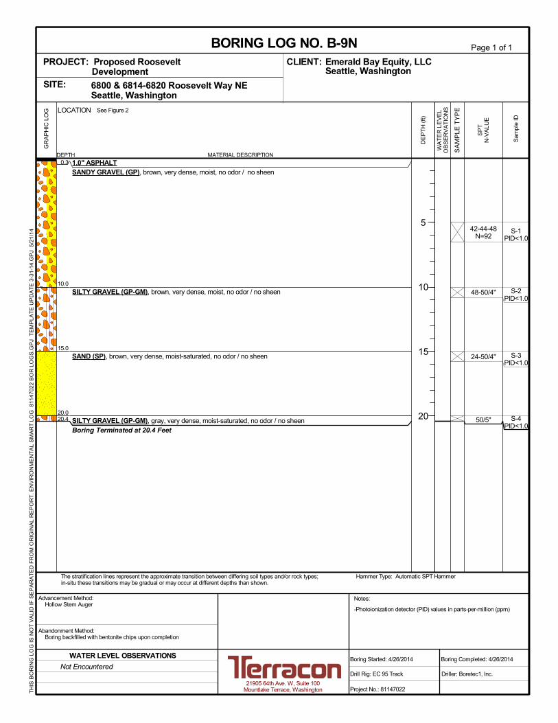
0.3
10.0
15.0
20.020.4
-Photoionization detector (PID) values in parts-per-million (ppm)
1.0" ASPHALTSANDY GRAVEL (GP), brown, very dense, moist, no odor / no sheen
SILTY GRAVEL (GP-GM), brown, very dense, moist, no odor / no sheen
SAND (SP), brown, very dense, moist-saturated, no odor / no sheen
SILTY GRAVEL (GP-GM), gray, very dense, moist-saturated, no odor / no sheenBoring Terminated at 20.4 Feet
42-44-48N=92
48-50/4"
24-50/4"
50/5"
S-1PID<1.0
S-2PID<1.0
S-3PID<1.0
S-4PID<1.0
LOCATION
DEPTH
The stratification lines represent the approximate transition between differing soil types and/or rock types;in-situ these transitions may be gradual or may occur at different depths than shown.
Hammer Type: Automatic SPT Hammer
GR
AP
HIC
LO
G See Figure 2
TH
IS B
OR
ING
LO
G IS
NO
T V
ALI
D IF
SE
PA
RA
TE
D F
RO
M O
RIG
INA
L R
EP
OR
T. E
NV
IRO
NM
EN
TA
L S
MA
RT
LO
G 8
1147
022
BO
R L
OG
S.G
PJ
TE
MP
LAT
E U
PD
AT
E 3
-31-
14.G
PJ
5/2
1/14
CLIENT:
6800 & 6814-6820 Roosevelt Way NE Seattle, WashingtonSITE:
PROJECT: Proposed RooseveltDevelopment
Page 1 of 1
Advancement Method:Hollow Stem Auger
Abandonment Method:Boring backfilled with bentonite chips upon completion
21905 64th Ave. W, Suite 100Mountlake Terrace, Washington
Notes:
Project No.: 81147022
Drill Rig: EC 95 Track
Boring Started: 4/26/2014
BORING LOG NO. B-9NEmerald Bay Equity, LLCSeattle, Washington
Driller: Boretec1, Inc.
Boring Completed: 4/26/2014
MATERIAL DESCRIPTION
SP
TN
-VA
LU
E
Sam
ple
ID
DE
PT
H (
ft)
5
10
15
20
WA
TE
R L
EV
EL
OB
SE
RV
AT
ION
S
SA
MP
LE T
YP
E
Not Encountered
WATER LEVEL OBSERVATIONS
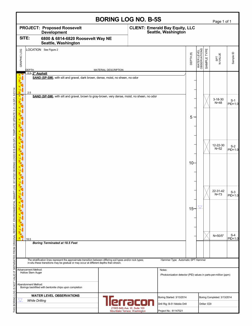
0.2
2.5
18.5
-Photoionization detector (PID) values in parts-per-million (ppm)
2" AsphaltSAND (SP-SM), with silt and gravel, dark brown, dense, moist, no sheen, no odor
SAND (SP-SM), with silt and gravel, brown to gray-brown, very dense, moist, no sheen, no odor
Boring Terminated at 18.5 Feet
3-18-30N=48
12-22-30N=52
22-31-42N=73
N=50/5"
S-1PID<1.0
S-2PID<1.0
S-3PID<1.0
S-4PID<1.0
LOCATION
DEPTH
The stratification lines represent the approximate transition between differing soil types and/or rock types;in-situ these transitions may be gradual or may occur at different depths than shown.
Hammer Type: Automatic SPT Hammer
GR
AP
HIC
LO
G See Figure 2
TH
IS B
OR
ING
LO
G IS
NO
T V
ALI
D IF
SE
PA
RA
TE
D F
RO
M O
RIG
INA
L R
EP
OR
T. E
NV
IRO
NM
EN
TA
L S
MA
RT
LO
G 8
1147
021
BO
RIN
G L
OG
S B
1S-B
7S.G
PJ
TE
MP
LAT
E U
PD
AT
E 3
-31-
14.G
PJ
5/2
1/14
CLIENT:
6800 & 6814-6820 Roosevelt Way NE Seattle, WashingtonSITE:
PROJECT: Proposed RooseveltDevelopment
Page 1 of 1
Advancement Method:Hollow Stem Auger
Abandonment Method:Borings backfilled with bentonite chips upon completion
21905 64th Ave. W, Suite 100Mountlake Terrace, Washington
Notes:
Project No.: 81147021
Drill Rig: B-51 Mobile Drill
Boring Started: 3/13/2014
BORING LOG NO. B-5SEmerald Bay Equity, LLCSeattle, Washington
Driller: EDI
Boring Completed: 3/13/2014
MATERIAL DESCRIPTION
SP
TN
-VA
LU
E
Sam
ple
ID
DE
PT
H (
ft)
5
10
15
WA
TE
R L
EV
EL
OB
SE
RV
AT
ION
S
SA
MP
LE T
YP
E
While Drilling
WATER LEVEL OBSERVATIONS
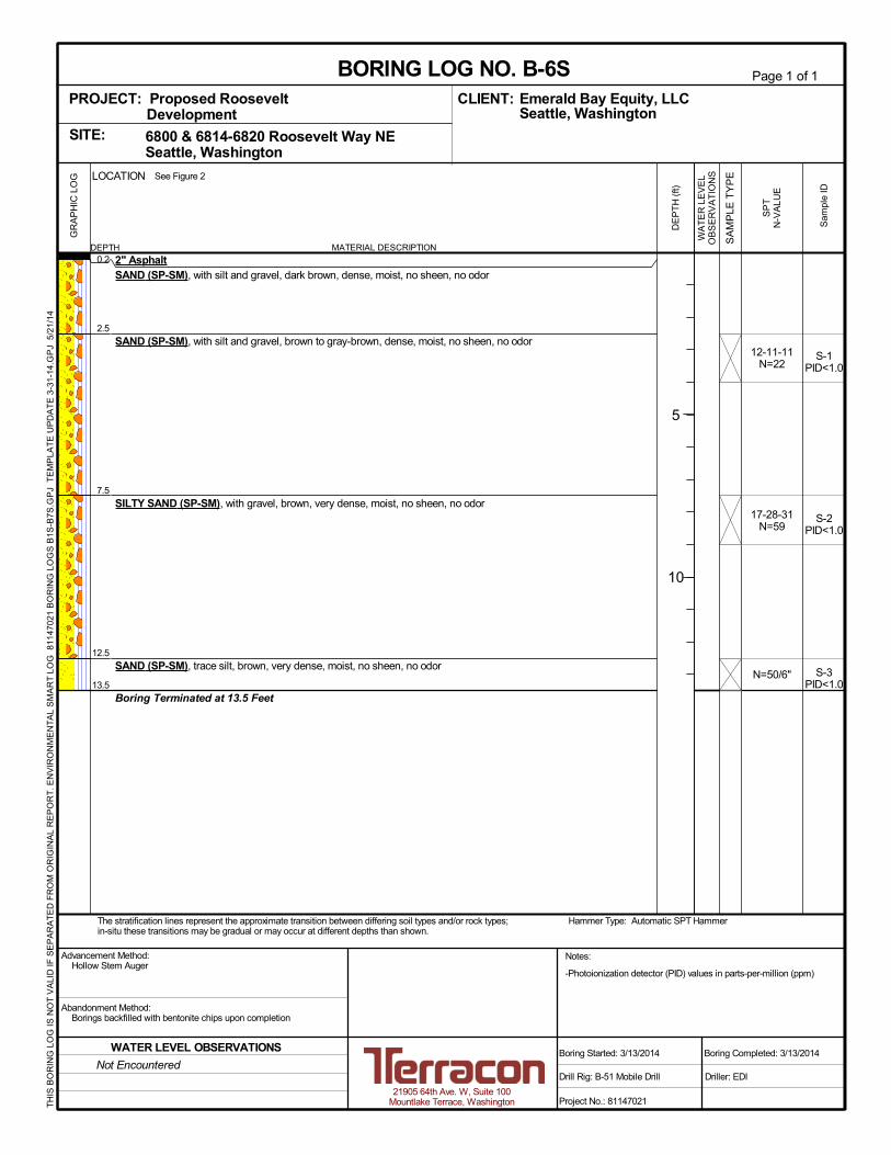
0.2
2.5
7.5
12.5
13.5
-Photoionization detector (PID) values in parts-per-million (ppm)
2" AsphaltSAND (SP-SM), with silt and gravel, dark brown, dense, moist, no sheen, no odor
SAND (SP-SM), with silt and gravel, brown to gray-brown, dense, moist, no sheen, no odor
SILTY SAND (SP-SM), with gravel, brown, very dense, moist, no sheen, no odor
SAND (SP-SM), trace silt, brown, very dense, moist, no sheen, no odor
Boring Terminated at 13.5 Feet
12-11-11N=22
17-28-31N=59
N=50/6"
S-1PID<1.0
S-2PID<1.0
S-3PID<1.0
LOCATION
DEPTH
The stratification lines represent the approximate transition between differing soil types and/or rock types;in-situ these transitions may be gradual or may occur at different depths than shown.
Hammer Type: Automatic SPT Hammer
GR
AP
HIC
LO
G See Figure 2
TH
IS B
OR
ING
LO
G IS
NO
T V
ALI
D IF
SE
PA
RA
TE
D F
RO
M O
RIG
INA
L R
EP
OR
T. E
NV
IRO
NM
EN
TA
L S
MA
RT
LO
G 8
1147
021
BO
RIN
G L
OG
S B
1S-B
7S.G
PJ
TE
MP
LAT
E U
PD
AT
E 3
-31-
14.G
PJ
5/2
1/14
CLIENT:
6800 & 6814-6820 Roosevelt Way NE Seattle, WashingtonSITE:
PROJECT: Proposed RooseveltDevelopment
Page 1 of 1
Advancement Method:Hollow Stem Auger
Abandonment Method:Borings backfilled with bentonite chips upon completion
21905 64th Ave. W, Suite 100Mountlake Terrace, Washington
Notes:
Project No.: 81147021
Drill Rig: B-51 Mobile Drill
Boring Started: 3/13/2014
BORING LOG NO. B-6SEmerald Bay Equity, LLCSeattle, Washington
Driller: EDI
Boring Completed: 3/13/2014
MATERIAL DESCRIPTION
SP
TN
-VA
LU
E
Sam
ple
ID
DE
PT
H (
ft)
5
10
WA
TE
R L
EV
EL
OB
SE
RV
AT
ION
S
SA
MP
LE T
YP
E
Not Encountered
WATER LEVEL OBSERVATIONS

0.2
12.0
18.0
-Photoionization detector (PID) values in parts-per-million (ppm)
2" AsphaltGRAVELLEY SAND (SP-SM), with silt, dark brown, loose to medium dense, moist, no sheen, no odor (FILL)
SILTY SAND (SP-SM), with gravel, gray, very dense, moist, no sheen, no odor
Boring Terminated at 18 Feet
5-6-5N=11
4-2-3N=5
N=50/6"
N=50/6"
S-1PID<1.0
S-2PID<1.0
S-3PID<1.0
S-4PID<1.0
LOCATION
DEPTH
The stratification lines represent the approximate transition between differing soil types and/or rock types;in-situ these transitions may be gradual or may occur at different depths than shown.
Hammer Type: Automatic SPT Hammer
GR
AP
HIC
LO
G See Figure 2
TH
IS B
OR
ING
LO
G IS
NO
T V
ALI
D IF
SE
PA
RA
TE
D F
RO
M O
RIG
INA
L R
EP
OR
T. E
NV
IRO
NM
EN
TA
L S
MA
RT
LO
G 8
1147
021
BO
RIN
G L
OG
S B
1S-B
7S.G
PJ
TE
MP
LAT
E U
PD
AT
E 3
-31-
14.G
PJ
5/2
1/14
CLIENT:
6800 & 6814-6820 Roosevelt Way NE Seattle, WashingtonSITE:
PROJECT: Proposed RooseveltDevelopment
Page 1 of 1
Advancement Method:Hollow Stem Auger
Abandonment Method:Borings backfilled with bentonite chips upon completion
21905 64th Ave. W, Suite 100Mountlake Terrace, Washington
Notes:
Project No.: 81147021
Drill Rig: B-51 Mobile Drill
Boring Started: 3/13/2014
BORING LOG NO. B-7SEmerald Bay Equity, LLCSeattle, Washington
Driller: EDI
Boring Completed: 3/13/2014
MATERIAL DESCRIPTION
SP
TN
-VA
LU
E
Sam
ple
ID
DE
PT
H (
ft)
5
10
15
WA
TE
R L
EV
EL
OB
SE
RV
AT
ION
S
SA
MP
LE T
YP
E
Not Encountered
WATER LEVEL OBSERVATIONS

0.5
12.5
22.5
25.0
-Well ID: BHZ-432-Photoionization detector (PID) values in parts-per-million (ppm)
2" AsphaltPOORLY GRADED SAND WITH SILT (SP-SM), with silt, gray, dense, moist, no sheen,no odor
POORLY GRADED SAND WITH SILT AND GRAVEL (SP-SM), with gravel, trace silt,brown to gray-brown, dense to very dense, moist-to-saturated, no sheen, no odor
SANDY SILT (ML), gray, very stiff, moist, no sheen, no odor
Boring Terminated at 25 Feet
12-20-23N=43
8-12-24N=36
15-14-23N=37
N=50/5"
17-29-45N=74
S-1PID=2.8
S-2PID<1.0
S-3PID<1.0
S-4PID<1.0
S-5PID<1.0
Concrete andflush monument
Bentonite seal
Sand
2" Slotted pipe
LOCATION
DEPTH
The stratification lines represent the approximate transition between differing soil types and/or rock types;in-situ these transitions may be gradual or may occur at different depths than shown.
Hammer Type: Automatic SPT Hammer
GR
AP
HIC
LO
G See Figure 2
TH
IS B
OR
ING
LO
G IS
NO
T V
ALI
D IF
SE
PA
RA
TE
D F
RO
M O
RIG
INA
L R
EP
OR
T. E
NV
IRO
NM
EN
TA
L S
MA
RT
LO
G 8
1147
021
BO
RIN
G L
OG
S M
W1-
MW
3.G
PJ
TE
MP
LAT
E U
PD
AT
E 3
-31-
14.G
PJ
5/2
1/14
CLIENT:
6800 & 6814-6820 Roosevelt Way NE Seattle, WashingtonSITE:
PROJECT: Proposed RooseveltDevelopment
Page 1 of 1
Advancement Method:Hollow Stem Auger
Abandonment Method:Boring completed as permanent monitoring well
21905 64th Ave. W, Suite 100Mountlake Terrace, Washington
Notes:
Project No.: 81147021
Drill Rig: B-51 Mobile Drill
Well Started: 3/12/2014
WELL LOG NO. MW-1SEmerald Bay Equity, LLCSeattle, Washington
Driller: EDI
Well Completed: 3/12/2014
MATERIAL DESCRIPTION
SP
TN
-VA
LU
E
Sam
ple
ID
DE
PT
H (
ft)
5
10
15
20
25
WA
TE
R L
EV
EL
OB
SE
RV
AT
ION
S
SA
MP
LE T
YP
E
Well Completion:
INSTALLATION DETAILS
While Drilling
WATER LEVEL OBSERVATIONS

0.5
12.5
17.5
25.0
-Well ID: BHZ-433-Photoionization detector (PID) values in parts-per-million (ppm)
2" AsphaltWELL GRADED SAND WITH SILT AND GRAVEL (SW-SM), trace silt and gravel, brown,very dense, moist, no sheen, no odor
SILTY SAND (SP-SM), grayish brown, dense, moist-to-saturated, no sheen, no odor
SAND (SP-SM), with silt and gravel, brown, very dense, saturated, no sheen, no odor
Boring Terminated at 25 Feet
N=50/6"
21-38-28N=66
20-13-20N=33
N=50/6"
N=50/3"
S-1
S-2PID<1.0
S-3PID<1.0
S-4PID<1.0
S-5PID<1.0
Concrete andflush monument
Bentonite seal
Sand
2" Slotted pipe
LOCATION
DEPTH
The stratification lines represent the approximate transition between differing soil types and/or rock types;in-situ these transitions may be gradual or may occur at different depths than shown.
Hammer Type: Automatic SPT Hammer
GR
AP
HIC
LO
G See Figure 2
TH
IS B
OR
ING
LO
G IS
NO
T V
ALI
D IF
SE
PA
RA
TE
D F
RO
M O
RIG
INA
L R
EP
OR
T. E
NV
IRO
NM
EN
TA
L S
MA
RT
LO
G 8
1147
021
BO
RIN
G L
OG
S M
W1-
MW
3.G
PJ
TE
MP
LAT
E U
PD
AT
E 3
-31-
14.G
PJ
5/2
1/14
CLIENT:
6800 & 6814-6820 Roosevelt Way NE Seattle, WashingtonSITE:
PROJECT: Proposed RooseveltDevelopment
Page 1 of 1
Advancement Method:Hollow Stem Auger
Abandonment Method:Boring completed as permanent monitoring well
21905 64th Ave. W, Suite 100Mountlake Terrace, Washington
Notes:
Project No.: 81147021
Drill Rig: B-51 Mobile Drill
Well Started: 3/12/2014
WELL LOG NO. MW-2SEmerald Bay Equity, LLCSeattle, Washington
Driller: EDI
Well Completed: 3/12/2014
MATERIAL DESCRIPTION
SP
TN
-VA
LU
E
Sam
ple
ID
DE
PT
H (
ft)
5
10
15
20
25
WA
TE
R L
EV
EL
OB
SE
RV
AT
ION
S
SA
MP
LE T
YP
E
Well Completion:
INSTALLATION DETAILS
While Drilling
WATER LEVEL OBSERVATIONS

0.5
11.0
30.0
-Well ID: BHZ-434-Photoionization detector (PID) values in parts-per-million (ppm)
2" AsphaltWELL GRADED SAND WITH SILT AND GRAVEL (SP-SM), with silt, dark brown,medium dense to dense, moist, no sheen, no odor (FILL)
POORLY GRADED SAND WITH SILT AND GRAVEL (SP-SM), with silt and gravel, gray,very dense, moist, no sheen, no odor
Boring Terminated at 30 Feet
6-7-8N=15
17-26-30N=56
N=50/6"
N=50/3"
N=50/2"
N=50/2"
S-1PID<1.0
S-2PID<1.0
S-3PID<1.0
S-4PID<1.0
S-5PID<1.0
S-6PID<1.0
Concrete andflush monument
Bentonite seal
Sand
2" Slotted pipe
LOCATION
DEPTH
The stratification lines represent the approximate transition between differing soil types and/or rock types;in-situ these transitions may be gradual or may occur at different depths than shown.
Hammer Type: Automatic SPT Hammer
GR
AP
HIC
LO
G See Figure 2
TH
IS B
OR
ING
LO
G IS
NO
T V
ALI
D IF
SE
PA
RA
TE
D F
RO
M O
RIG
INA
L R
EP
OR
T. E
NV
IRO
NM
EN
TA
L S
MA
RT
LO
G 8
1147
021
BO
RIN
G L
OG
S M
W1-
MW
3.G
PJ
TE
MP
LAT
E U
PD
AT
E 3
-31-
14.G
PJ
5/2
1/14
CLIENT:
6800 & 6814-6820 Roosevelt Way NE Seattle, WashingtonSITE:
PROJECT: Proposed RooseveltDevelopment
Page 1 of 1
Advancement Method:Hollow Stem Auger
Abandonment Method:Boring completed as permanent monitoring well
21905 64th Ave. W, Suite 100Mountlake Terrace, Washington
Notes:
Project No.: 81147021
Drill Rig: B-51 Mobile Drill
Well Started: 3/12/2014
WELL LOG NO. MW-3SEmerald Bay Equity, LLCSeattle, Washington
Driller: EDI
Well Completed: 3/12/2014
MATERIAL DESCRIPTION
SP
TN
-VA
LU
E
Sam
ple
ID
DE
PT
H (
ft)
5
10
15
20
25
30
WA
TE
R L
EV
EL
OB
SE
RV
AT
ION
S
SA
MP
LE T
YP
E
Well Completion:
INSTALLATION DETAILS
Not Encountered
WATER LEVEL OBSERVATIONS

APPENDIX B
SUPPORTING DOCUMENTS

Exhibit B-1
GENERAL NOTES
DRILLING & SAMPLING SYMBOLS:
SS: Split Spoon – 1-3/8" I.D., 2" O.D., unless otherwise noted HS: Hollow Stem Auger
ST: Thin-Walled Tube - 3" O.D., unless otherwise noted PA: Power Auger
RS: Ring Sampler - 2.42" I.D., 3" O.D., unless otherwise noted HA: Hand Auger
DB: Diamond Bit Coring - 4", N, B RB: Rock Bit
BS: Bulk Sample or Auger Sample WB: Wash Boring or Mud Rotary
The number of blows required to advance a standard 2-inch O.D. split-spoon sampler (SS) the last 12 inches of the total 18-inch
penetration with a 140-pound hammer falling 30 inches is considered the “Standard Penetration” or “N-value”.
WATER LEVEL MEASUREMENT SYMBOLS:
WL: Water Level WS: While Sampling N/E: Not Encountered
WCI: Wet Cave in WD: While Drilling
DCI: Dry Cave in BCR: Before Casing Removal
AB: After Boring ACR: After Casing Removal
Water levels indicated on the boring logs are the levels measured in the borings at the times indicated. Groundwater levels at other
times and other locations across the site could vary. In pervious soils, the indicated levels may reflect the location of groundwater.
In low permeability soils, the accurate determination of groundwater levels may not be possible with only short-term observations.
DESCRIPTIVE SOIL CLASSIFICATION: Soil classification is based on the Unified Soil Classification System. Coarse Grained Soils
have more than 50% of their dry weight retained on a #200 sieve; their principal descriptors are: boulders, cobbles, gravel or sand.
Fine Grained Soils have less than 50% of their dry weight retained on a #200 sieve; they are principally described as clays if they are
plastic, and silts if they are slightly plastic or non-plastic. Major constituents may be added as modifiers and minor constituents may
be added according to the relative proportions based on grain size. In addition to gradation, coarse-grained soils are defined on the
basis of their in-place relative density and fine-grained soils on the basis of their consistency.
CONSISTENCY OF FINE-GRAINED SOILS RELATIVE DENSITY OF COARSE-GRAINED SOILS
Unconfined
Compressive
Strength, Qu, psf
Standard Penetration or N-value (SS)
Blows/Ft. Consistency
Standard Penetration or N-value (SS)
Blows/Ft.
Ring Sampler (RS) Blows/Ft.
Relative Density
< 500 0-1 Very Soft 0 – 3 0-6 Very Loose
500 – 1,000 2-3 Soft 4 – 9 7-18 Loose
1,001 – 2,000 4-6 Medium Stiff 10 – 29 19-58 Medium Dense
2,001 – 4,000 7-12 Stiff 30 – 49 59-98 Dense
4,001 – 8,000 13-26 Very Stiff 50+ 99+ Very Dense
8,000+ 26+ Hard
RELATIVE PROPORTIONS OF SAND AND GRAVEL GRAIN SIZE TERMINOLOGY
Descriptive Term(s) of other
Constituents
Percent of
Dry Weight
Major Component
of Sample Particle Size
Trace < 15 Boulders Over 12 in. (300mm)
With 15 – 30 Cobbles 12 in. to 3 in. (300mm to 75 mm)
Modifier > 30 Gravel 3 in. to #4 sieve (75mm to 4.75 mm)
Sand
Silt or Clay
#4 to #200 sieve (4.75mm to 0.075mm)
Passing #200 Sieve (0.075mm)
RELATIVE PROPORTIONS OF FINES PLASTICITY DESCRIPTION
Descriptive Term(s) of other
Constituents
Percent of
Dry Weight Term
Plasticity
Index
Trace < 5 Non-plastic 0
With 5 – 12 Low 1-10
Modifier > 12 Medium 11-30
High 30+
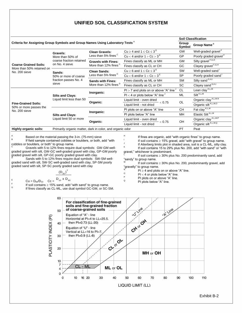
Exhibit B-2
UNIFIED SOIL CLASSIFICATION SYSTEM
Criteria for Assigning Group Symbols and Group Names Using Laboratory Tests A
Soil Classification
Group Symbol
Group Name B
Coarse Grained Soils: More than 50% retained on No. 200 sieve
Gravels: More than 50% of coarse fraction retained on No. 4 sieve
Clean Gravels: Less than 5% fines
C
Cu 4 and 1 Cc 3 E
GW Well-graded gravel F
Cu 4 and/or 1 Cc 3 E
GP Poorly graded gravel F
Gravels with Fines: More than 12% fines
C
Fines classify as ML or MH GM Silty gravel F,G,H
Fines classify as CL or CH GC Clayey gravel F,G,H
Sands: 50% or more of coarse fraction passes No. 4 sieve
Clean Sands: Less than 5% fines
D
Cu 6 and 1 Cc 3 E
SW Well-graded sand I
Cu 6 and/or 1 Cc 3 E
SP Poorly graded sand I
Sands with Fines: More than 12% fines
D
Fines classify as ML or MH SM Silty sand G,H,I
Fines classify as CL or CH SC Clayey sand G,H,I
Fine-Grained Soils: 50% or more passes the No. 200 sieve
Silts and Clays: Liquid limit less than 50
Inorganic: PI 7 and plots on or above “A” line
J CL Lean clay
K,L,M
PI 4 or plots below “A” line J ML Silt
K,L,M
Organic: Liquid limit - oven dried
0.75 OL Organic clay
K,L,M,N
Liquid limit - not dried Organic silt K,L,M,O
Silts and Clays: Liquid limit 50 or more
Inorganic: PI plots on or above “A” line CH Fat clay
K,L,M
PI plots below “A” line MH Elastic Silt K,L,M
Organic: Liquid limit - oven dried
0.75 OH Organic clay
K,L,M,P
Liquid limit - not dried Organic silt K,L,M,Q
Highly organic soils: Primarily organic matter, dark in color, and organic odor PT Peat
A Based on the material passing the 3-in. (75-mm) sieve
B If field sample contained cobbles or boulders, or both, add “with
cobbles or boulders, or both” to group name. C
Gravels with 5 to 12% fines require dual symbols: GW-GM well-graded gravel with silt, GW-GC well-graded gravel with clay, GP-GM poorly graded gravel with silt, GP-GC poorly graded gravel with clay. D
Sands with 5 to 12% fines require dual symbols: SW-SM well-graded sand with silt, SW-SC well-graded sand with clay, SP-SM poorly graded sand with silt, SP-SC poorly graded sand with clay
E Cu = D60/D10 Cc = 6010
2
30
DxD
)(D
F
If soil contains 15% sand, add “with sand” to group name. G
If fines classify as CL-ML, use dual symbol GC-GM, or SC-SM.
H If fines are organic, add “with organic fines” to group name.
I If soil contains 15% gravel, add “with gravel” to group name.
J If Atterberg limits plot in shaded area, soil is a CL-ML, silty clay.
K If soil contains 15 to 29% plus No. 200, add “with sand” or “with
gravel,” whichever is predominant. L
If soil contains 30% plus No. 200 predominantly sand, add “sandy” to group name. M
If soil contains 30% plus No. 200, predominantly gravel, add “gravelly” to group name. N
PI 4 and plots on or above “A” line. O
PI 4 or plots below “A” line. P
PI plots on or above “A” line. Q
PI plots below “A” line.