geotechnical engineering services report southern …
TRANSCRIPT

GEOTECHNICAL ENGINEERING SERVICES REPORT
JOB NO. 1-10302
SOUTHERN SANDOVAL COUNTY ARROYO & FLOOD CONTROL AUTHORITY
HARLEY POND PROJECT
RIO RANCHO, NEW MEXICO
PREPARED FOR:
RESPEC

April 16, 2021 Job No. 1-10302 RESPEC 5971 Jefferson St. NE, Suite 101 Albuquerque, NM 87109 ATTN: E. Christian Naidu, PE RE: Geotechnical Engineering Services Report SSCAFCA
Harley Pond Project Rio Rancho, New Mexico
Dear Mr. Naidu: Submitted herein is the Geotechnical Engineering Services Report for the above referenced project. The report contains the results of our field investigation and laboratory testing as well as embankment foundation and construction, slope stability, excavation and site grading recommendations. It has been a pleasure to serve you on this project. If you should have any questions, please contact this office. Respectfully submitted: GEO-TEST, INC. Reviewed By: Patrick R. Whorton, PE Robert D. Booth, PE
Table of Contents
INTRODUCTION ............................................................................................ 4
PROPOSED CONSTRUCTION ..................................................................... 4
FIELD EXPLORATION .................................................................................. 4
LABORATORY TESTING .............................................................................. 5
SITE CONDITIONS ........................................................................................ 5
SUBSURFACE SOIL CONDITIONS .............................................................. 5
CONCLUSIONS AND RECOMMENDATIONS .............................................. 6
DAM EMBANKMENT FOUNDATION ............................................................ 6
DAM EMBANKMENT CONSTRUCTION ....................................................... 7
INLET AND OUTLET STRUCTURES ............................................................ 8
SEEPAGE AND INTERNAL DRAINAGE ....................................................... 8
EROSION ...................................................................................................... 8
SITE GRADING ............................................................................................. 9
EXCAVATIONS ............................................................................................ 10
REVIEW AND INSPECTION........................................................................ 11
CLOSURE .................................................................................................... 11
CONCEPTUAL SITE PLAN ......................................................................... 13
BORING LOCATION MAP ........................................................................... 14
BORING LOGS ............................................................................................ 15
SUMMARY OF LABORATORY RESULTS .................................................. 25
GRAIN SIZE DISTRIBUTION....................................................................... 29
MOISTURE/DENSITY (PROCTOR) RESULTS ........................................... 33
PERMEABILITY RESULTS ......................................................................... 35

Harley Pond Project Page 4 Job No. 1-10302 April 16, 2021
Copyright© 2021, GEO-TEST, INC.
INTRODUCTION This report presents the results of geotechnical engineering services performed by this firm for the proposed new Harley Pond Project to be constructed in Rio Rancho, New Mexico. The objectives of this investigation were to:
1) Evaluate the nature and engineering properties of the soils underlying the dam and pond site.
2) Provide recommendations for the design and construction of the
detention pond including embankment foundation preparation and construction, considering slope stability, settlement, and seepage.
The investigation includes subsurface exploration, representative soil sampling, laboratory testing of the samples, performing an engineering analysis and preparation of this report. PROPOSED CONSTRUCTION It is understood that the project consists of the construction of a flood control pond located south of the intersection of Vargas Rd. and Vicenza Dr. in Rio Rancho. The pond will be constructed by excavating the native soils on the west side of the site to a depth of approximately 10 feet below existing surface grades at a 3:1 slope. The excavated soils will be used to construct an embankment dam located on the east side of the site. The embankment dam will be 8 feet high with a 3:1 slope on the upstream side of the dam and sloped on the downstream side at a 4:1 slope to native grade approximately 18 feet below the crest of the dam which is 15 feet wide. The primary outlet for the pond will be a drop inlet structure located on the southern side of the pond within the cut area. The drop inlet will feed into reinforced concrete pipes connected to the city storm sewer system. An emergency spillway weir will be constructed on the northern portion of the pond with an associated concrete lined channel. The inlet to the pond will be a concrete lined channel at the approximate location of an existing arroyo located at the northern portion of the pond. A conceptual site plan is included as Figure 1 in a later section of this report. FIELD EXPLORATION A total of ten (10) exploratory borings were drilled at the site. Five (5) borings were drilled to a depth of 25 feet below existing grades along the alignment of the proposed dam embankment while five (5) borings were drilled to a depth of 15 feet below existing grades within the detention pond area. The locations of the borings are shown on the attached Boring Location Maps, Figure 2. During the test drilling, the soils encountered in the borings were continuously examined, visually classified, and logged. The boring logs are presented in a following section of this report. Drilling was accomplished with a truck mounted

Harley Pond Project Page 5 Job No. 1-10302 April 16, 2021
Copyright© 2021, GEO-TEST, INC.
drill rig using 5.5-inch diameter continuous flight hollow stem auger. Subsurface materials were sampled at five foot intervals or less utilizing an open tube split barrel sampler driven by a standard penetration test hammer. Bulk samples of auger cuttings were also collected. LABORATORY TESTING Selected samples were tested in the laboratory to determine certain engineering properties of the soils. Moisture contents were determined to evaluate the various soil deposits with depth. The results of these tests are presented on the boring logs. Sieve analysis and Atterberg limits tests were performed on selected samples to aid in soil classification. In addition, moisture-density relationship tests were performed on composite bulk samples to determine the optimum moisture content and maximum dry density of blended onsite soils. Re-molded permeability testing was also performed on selected samples to determine hydraulic conductivity of the compacted soils. The results of these tests are presented in the Summary of Laboratory Results and on the individual test reports presented in a following section of this report. SITE CONDITIONS The Harley Pond site is located approximately 1,800 feet north of the intersection of Westside Blvd. and 10th St. SE in Rio Rancho. The area is generally undeveloped; 10th St. is rough cut through the site and a city water line was recently installed through the southern portion of this site, beyond these improvements, the site is in a native state. There are two arroyos which enter the site from the west (Viccenza Dr.) and currently exit the site along the east side (11th St.). The arroyos are in a general native state with no engineered improvements. Some garbage has been dumped on the site, particularly at the intersections of 10th St. and the arroyos. This garage appears to be household debris which appears to be recently deposited and limited to the surface. The overall site slopes downward from southwest to northeast with a total grade change on the order of 25 feet. There are also localized elevation changes throughout. The site is populated with native shrubs and grasses. SUBSURFACE SOIL CONDITIONS As indicated by the exploratory borings, the subsurface profile underlying the Harley Pond site consists primarily of non-plastic silty and poorly graded sands which were encountered at the surface and extended to the full depths explored. Based on standard penetration testing, the relative density of these soils was found to be loose to medium dense near the surface becoming dense to very dense with depth. In half of the exploratory borings, a layer of cemented sand, commonly referred to as caliche, was encountered at depths ranging from 2.5 feet to 12.5 feet below surface grade. The degree of

Harley Pond Project Page 6 Job No. 1-10302 April 16, 2021
Copyright© 2021, GEO-TEST, INC.
cementation and thickness of the caliche varied from each location tested. See boring logs included in a later section of this report for specific soil profiles. No free groundwater was encountered in the borings and soil moisture contents were relatively low throughout the extent of the borings. CONCLUSIONS AND RECOMMENDATIONS The native soils encountered throughout the site are considered suitable for use as structural fill and may be used for the construction of the dam embankment. The density of near surface soils beneath the dam site are generally loose to medium dense and most soils were found to have a low moisture content and would be likely to experience settlement upon significant moisture increase. Therefore, in order to provide a stable and uniform surface for the construction of the dam, it is recommended that the subsurface soils beneath the dam, which will comprise the dam foundation, be overexcavated to such an extent as to provide for a minimum of 3 feet of properly compacted structural fill beneath the embankment. The limits of the overexcavation should also and extend a minimum distance of 3 feet beyond the perimeter of the dam. Detailed recommendations for dam embankment design and the required site grading are presented in the following sections of this report. The native soils encountered at the pond area may be readily excavated using normal earthmoving equipment and may be reused as structural fill for the construction of the dam embankment, although some blending may be required to meet the specifications for structural fill. Cut slopes may be excavated at a maximum temporary slope of 1.5:1 (H:V) and permanent slopes should be graded or created at slopes as described in the Dam Embankment Construction section of this report. DAM EMBANKMENT FOUNDATION Clearing, grubbing and stripping will be required over the entire embankment foundation areas extending a distance of at least 3 feet horizontally beyond the limits of the embankment. The resulting foundation areas should then be overexcavated to such an extent as to provide for a minimum 3 feet of structural fill beneath the embankment. The overexcavation should also extend a minimum of 3 feet laterally from the embankment perimeter. Once the overexcavation has been completed, the native cut surface should be densified, and the embankment constructed in accordance with the Site Grading section of this report. Total settlement of the embankment is a function of internal embankment settlement and foundation settlement. Maximum foundation settlements are estimated to be on the order of 1½ inches, and internal embankment settlements are estimated to be on the order of 1 inch or less. However, since the vast majority of both foundation and embankment settlements will be elastic and occur during construction, only minor settlement, less than ¾ inch is anticipated upon completion of construction.

Harley Pond Project Page 7 Job No. 1-10302 April 16, 2021
Copyright© 2021, GEO-TEST, INC.
DAM EMBANKMENT CONSTRUCTION Embankments should meet the specifications and be constructed according to the method outlined within the Site Grading section of this report. Based on the results of this investigation; it is anticipated that the majority of native soils encountered throughout the site will be suitable for use as dam embankment fill, although some blending will be required to provide for a homogenous fill meeting the specifications outlined within the Site Grading section of this report. The stability of constructed dam embankment slopes was analyzed using the two-dimensional limit equilibrium stability program STABLPRO by Ensoft. Bishop’s Method of Slices was used to develop factors of safety against slip on a circular failure plane for both static and pseudo-static loading conditions for three anticipated slopes to be used in pond construction are presented below in terms of factors of safety with a factor of 1 being stable, less than 1 unstable, 2 recommended for static conditions and 1.3 recommended for pseudo-static conditions. Embankments with a lesser height, wider crest and flatter slope will have factors of safety higher than those listed above such that they would also be deemed acceptable. It is assumed that the native sands encountered will be the primary material utilized for the construction of the embankment slopes. The slope stability analysis was conducted using the soil characteristics of the sampled onsite material such that the calculated slope stability applies only to these materials. Should import material be required for embankment construction, the soils should conform to the structural fill requirements presented in the Site Grading section of this report and be approved by the geotechnical engineer. For the purposes of this analysis, a horizontal pseudo-static coefficient of 0.20g was utilized in the analyses based on 100% of the predicted peak ground acceleration within 50 years with a 2 percent probability of exceedance. Should alternative embankment configurations be considered which do not conform to the embankment configurations and dimensions discussed above, this firm should be notified, and additional slope stability analysis can be performed for the embankment design chosen.
Slope (H:V) Height (ft) Static FS Pseudo-Static FS 3:1 8 3.181 1.989
3:1 Cut 12 2.607 1.524 4:1 18 3.696 1.928

Harley Pond Project Page 8 Job No. 1-10302 April 16, 2021
Copyright© 2021, GEO-TEST, INC.
INLET AND OUTLET STRUCTURES The principal outlet for Harley Pond will consist of a drop inlet structure connected to a 24-inch diameter reinforced concrete pipe that will discharge into a storm sewer system. The drop inlet structure and RCP will be placed within a cut area of the pond. As these structures will not be supported by the embankment foundation, it is recommended overexcavation be conducted to provide for a minimum of 3 feet of structural fill beneath the drop inlet structure. In addition, the excavation for the pipe should be overexcavated to provide a minimum of 3 feet of properly compacted structural fill surrounding the entire pipe. The pipe should then be backfilled with structural fill meeting the requirements presented in the Site Grading section of this report. The inlet channel to the pond as well as the emergency spillway weir and rundown channel will be constructed with concrete or shotcrete slabs on grade. Prior to the placement of the concrete or shotcrete, the subgrade should be scarified to a depth of 12 inches, moisture conditioned to optimum moisture or above and compacted to 95 percent or greater of maximum density as determined by ASTM D-1557. Riprap to be used in energy dissipation areas should also be placed on a minimum of 12 inches of compacted subgrade as prepared for the concrete. SEEPAGE AND INTERNAL DRAINAGE The project consists of a flood control structure to be constructed on normally dry watercourse. Maximum storm water detention time is anticipated to be 24 hours or less. Based upon the results of the laboratory tests, this is not nearly enough time to develop steady state seepage. Accordingly, seepage analysis and internal drainage design is not considered necessary. In addition, filter/drain material around the principal spillway or within the embankment itself to control seepage is not considered necessary provided the embankment fill is carefully placed around the pipe as recommended in the Site Grading section of this report. EROSION The onsite soils anticipated to be used as dam embankment fill and which will comprise cut slopes throughout the project are low cohesive granular soils. As such, slopes constructed with these soils will be subject to both sheet and rill erosion. As a general rule the amount of erosion to be expected is directly related to how steep the slope in question is with steeper slopes experiencing more erosion that flatter slopes. As stated in previous sections, permanent project slopes may be as steep as 3:1. Although stable, these steeper slopes will likely experience greater erosion than flatter slopes which may compromise the stability and integrity of the slopes. Therefore, the stability of all slopes recommended herein should be considered contingent upon the implementation of proper erosion protection.

Harley Pond Project Page 9 Job No. 1-10302 April 16, 2021
Copyright© 2021, GEO-TEST, INC.
The area immediately surrounding the drop inlet structure of the primary outlet will be particularly susceptible to erosion which may compromise the adjacent cut slope. As such, it is recommended that riprap or other erosion protection be installed around the drop inlet and placed to protect the adjacent cut slope. SITE GRADING The following general guidelines should be included in the project construction specifications to provide a basis for quality control during site grading. It is recommended that all structural fill and backfill be placed and compacted under engineering observation and in accordance with the following:
1) Clearing, grubbing and stripping will be required over the entire dam embankment foundation areas. Stumps, matted roots, or rocks larger than 2 inches in diameter should be removed from within 18 inches of the foundation areas. Stripping and preparation of dam embankment foundation areas should extend a minimum of 3 feet horizontally beyond embankment limits. Stripping should be achieved only by cutting, i.e., ground depressions or narrow sections of tributary arroyos should not be inadvertently filled during the foundation preparation.
2) After clearing, grubbing and required excavations, the existing site soils
throughout the foundation areas should be overexcavated to such an extent as to provide for at least 3 feet of properly compacted structural fill beneath the dam embankments and outlet pipe. The overexcavation limits should extend laterally a minimum of 3 feet beyond the embankment and pipe perimeters. The soils exposed at the base of the overexcavation should be densified before placement of structural fill.
3) Densification of native cut surfaces shall consist of moisture
conditioning to the optimum moisture content or above. The upper 12 inches should then be compacted to a minimum of 95 percent of the maximum dry density at or above the optimum moisture content as determined in accordance with ASTM D-1557.
4) The results of this investigation indicate that most of the native soils will
be suitable for use as structural fill; however, some blending may be required to meet the specifications below. Should imported fill be required, it should also meet the specifications for structural fill.
5) All structural fill and backfill should be free of vegetation and debris and
contain no rocks larger than 3 inches. Gradation of the backfill material, as determined in accordance with ASTM D-422, should be as follows:
Size Percent Passing 3 inch 100 No. 4 60 - 100
No. 200 10 - 35
Harley Pond Project Page 10 Job No. 1-10302 April 16, 2021
Copyright© 2021, GEO-TEST, INC.
6) Fill or backfill, consisting of soil approved by the geotechnical engineer, should be placed in controlled compacted layers not exceeding 8 inches (compacted) with approved compaction equipment. All structural fill material should be blended as necessary to produce a homogeneous embankment. No lifts of high permeability material or material differing substantially from the lift below should be permitted. Sheepsfoot or vibratory sheepsfoot or segmented steel wheel type compactors should be used. If the compactors “walk out” during compaction, or if it is desired to use flat wheel compactors, the upper 1 to 2 inches of the lift should be scarified prior to placing a subsequent lift. The embankment should be raised uniformly. All compaction should be accomplished to a minimum of 95 percent of maximum dry density as determined in accordance with ASTM D-1557. The moisture content of the structural fill during compaction should be at or 3 percent above the optimum moisture content. With any vibratory compactor, vibrations should be controlled or eliminated to avoid damage to adjacent structures or infrastructure.
7) Fill below and above the principal spillway pipe should be placed and
compacted as outlined above. In the zone within 3 feet of the pipe, fill should be placed in maximum 6 inch lifts, moisture conditioned and compacted as outlined above, using manually controlled walk behind rolling compactors, vibratory plate compactors or jumping jacks capable of compacting the soil immediately adjacent to and beneath the haunches of the pipe. Continuous observation and testing should be performed by a representative of the geotechnical engineer during the backfilling process to verify proper placement and compaction around the pipes.
8) Tests for degree of compaction should be determined in accordance
with ASTM D-1556 or ASTM D-6938. Continuous, full time observation and field tests should be conducted during fill and backfill placement by a representative of the geotechnical engineer to assist the contractor in evaluating the required degree of compaction. If less than the required compaction is required, additional compaction effort should be made with adjustment of the moisture content as necessary until 95 percent compaction is obtained.
EXCAVATIONS The results of this investigation indicate that the surficial soils can be readily excavated using normal earth moving and excavation equipment. Temporary construction excavations should be maintained at slopes of 1.5:1 (H:V) or flatter. Surcharge loads including construction traffic and excavated spoil materials should be maintained at least 10 feet from the crest of any excavation slope. Surface water should be routed such that it does not flow down the face of the excavation slopes. Where insufficient space exists for open cut excavations, a shoring system will be required. All excavations should comply with all applicable safety regulations.
Harley Pond Project Page 11 Job No. 1-10302 April 16, 2021
Copyright© 2021, GEO-TEST, INC.
Experience dictates shrinkage factors greater than calculated values. Stripping, subgrade preparation, hauling and wind losses, and ground compaction, both in the borrow (reservoir) areas and within the embankment foundation areas are all factors in shrinkage. We recommend using a shrinkage factor on the order of 25 percent. REVIEW AND INSPECTION This report has been prepared to aid in the evaluation of this site and to assist in the design of this project. It is recommended that the geotechnical engineer be provided the opportunity to review the final design drawings and specifications in order to determine whether the recommendations in this report are applicable to the final design. Review of the final design drawings and specifications should be noted in writing by the geotechnical engineer. In order to permit correlation between the conditions encountered during construction and to confirm recommendations presented herein, it is recommended that the geotechnical engineer be retained to perform continuous observations and testing during the earthwork portion of this project. Observation and testing should be performed during construction to confirm that suitable fill and embankment soils are placed upon competent materials. CLOSURE Our conclusions, recommendations and opinions presented herein are:
1) Based upon our evaluation and interpretation of the findings of the field and laboratory program.
2) Based upon an interpolation of soil conditions between and beyond the
explorations.
3) Subject to confirmation of the conditions encountered during construction.
4) Based upon the assumption that sufficient observation will be provided
during construction.
5) Prepared in accordance with generally accepted professional geotechnical engineering principles and practice.
This report has been prepared for the sole use of RESPEC, specifically to aid in the design of the proposed Harley Pond Project in Rio Rancho, New Mexico, and not for use by any third parties without consent. We make no other warranty, either expressed or implied. Any person using this report for bidding or construction purposes should perform such independent investigation as they deem necessary to satisfy themselves as to

Harley Pond Project Page 12 Job No. 1-10302 April 16, 2021
Copyright© 2021, GEO-TEST, INC.
the surface and subsurface conditions to be encountered and the procedures to be used in the performance of work on this project. If conditions encountered during construction appear to be different than indicated by this report, this office should be notified. All soil samples will be discarded 60 days after the date of this report unless we receive a specific request to retain the samples for a longer period of time.

W
W
W
W
W
W
W
11th
STR
EET
VARGAS RD
10th
STR
EET
VIGA RD
TOP OF DAM = 5458
PRINCIPAL OUTLET INVERT = 5447
APPROX FUTURE 10THSD MH # 17
INVERT = 5446.56
EXISTING CMP INV = 5433±
PLUNGE POOL
PLUNGE POOL
4
PLUNGE POOL
3
3
1
1
1
1
1
1
20' x 8' CONCRETE PAD
1
112
15'
2
2
WEIR INVERT = 5453
EMERGENCY SPILLWAY WEIR INVERT = 5457
2
5465
5470
5460
5450
5445
5455
5455
5450
5465
546554
70
5460
5455
5450
5460
5460
5455
5450
5445
54555450 5455
5455
5450
5475
5460
5455
5445
5440
5440
5435
5430
5430
5435
5430
5435
5440
5445
5450
5445
5450
5470
5470
5465
5460
5455
5455
5455
5455
5450
5475
5475
5465
5465
5470
5470
5450
5470
5450
5435
5440
5465
5460
5465
54705469
36" S
D36
" SD
24" S
D
10:1
3:1
18" SD
0.5%
A
B
B
A
GRADE CONTROL INVERT = 5465
TRIB
UTA
RY
A
3:1
4:1
15'
1
3.9%
4.9%
Q100 =
356.7
Q500 =
521.1
Scale: N.T.S.SECTION B - EMERGENCY SPILLWAY CHANNEL
EXISTINGGROUND
COMPACTEDSUBGRADE
SHOTCRETE/CONCRETE
Scale: N.T.S.SECTION A - INLET RUNDOWN
SHOTCRETE/CONCRETE
COMPACTEDSUBGRADE
EXISTINGGROUND
6"
12'
4"
12'
2'1'
0 60 120
SCALE IN FEET
RESPEC
RESPEC
EXHIBIT AHARLEY'S PONDCONCEPTUAL DESIGN
APRIL 16, 2021
LEGEND
STORM DRAIN
EMERGENCY SPILLWAY
PROPERTY ACCESS ROAD
POND MAINTENANCEACCESS ROAD
SHOTCRETE
RIPRAP
NAM
E: N
:\Pro
ject
s\W
0005
SSC
AFC
A O
n C
all\W
0005
.210
01 H
arle
y Po
nd D
esig
n\3.
DW
G\E
xhib
its\E
XHIB
IT A
- D
AR E
xhib
it.dw
g PL
OT
DAT
E: A
pr 1
5, 2
021
2:3
8pm
COMMUNITY DESIGN SOLUTIONS5971 JEFFERSON STREET SUITE 101ALBUQUERQUE, NEW MEXICO 87109
WWW.RESPEC.COM PHONE: (505)253-9718
POND STORAGE VOLUME = 39.9 AC-FT
SEWER CONSTRUCTION NOTESI.D.# DESCRIPTION
RE-SEEDING WITH 1" ROCK MULCH, 2" DEEP
5 STRAND BARBLESS WIRE FENCE
RE-SEEDING WITH NATIVE SEEDING
1
2
3
48" MANHOLE WITH BEEHIVE GRATE INLET4
Geo-Test 1-10302 Figure 1

Figure 2Harley Pond ProjectRio Rancho, New MexicoJob No. 1-10302
1
2
34
5
6
7
8
9
10

SS
SS
SS
SS
SS
SS
SS
SILTY SAND, non-plastic, medium dense,dry, light brown
Slightly Cemented SILTY SAND (Caliche),non-plastic, medium dense, dry, lightbrown/white
POORLY GRADED SAND, non-plastic,medium dense to dense, dry, gray
Stopped Auger @ 24 feetStopped Sampler @ 25.5 feet
5
5
3
3
2
1
1
1-5-813
6-8-715
7-6-511
5-6-814
6-9-1019
15-19-2443
15-19-2342
SM
SM
SP
Project:
Date:
Elevation:
Harley Pond Project
04/02/2021
During Drilling: none
LEGEND
LOG OF TEST BORINGS
LOG
SA
MP
LEIN
TE
RV
AL
Nblows/ft
20 40 60 80TY
PE
Stratification lines represent approximate boundaries between soil types. Transitions may be gradual. Water level readingshave been made at times and under conditions stated. Fluctuations of groundwater may occur due to factors other than thosepresent at the time measurments were made.
NO: 1
SAMPLE
GROUNDWATER DEPTH
SUBSURFACE PROFILE
Project No:
Type:
1-10302
5.5" OD HSA
DESCRIPTION
DE
PT
H (
Ft)
5
10
15
20
25
30
MO
IST
UR
E% D
RY
DE
NS
ITY
(pcf
)
After 24 Hours:
N.
BLO
WS
/FT
AMSL - Above Mean Sea LevelCS - Continuous SamplerUD - UndisturbedST - Shelby Tube
SS - Split SpoonAC - Auger CuttingsUD/SL - Undisturbed Sleeve
US
C
LOG
OF
TE
ST
BO
RIN
G 1
-103
02.G
PJ
GE
O T
ES
T.G
DT
4/
14/2
1
13
15
11
14
19
43
42

SS
SS
SS
SS
SS
SS
SS
POORLY GRADED SAND with SILT,non-plastic, loose to medium dense, dry,light brown
POORLY GRADED SAND, non-plastic,medium to very dense, dry, gray
Stopped Auger @ 24 feetStopped Sampler @ 25.5 feet
3
2
2
2
3
3
4
3-3-69
7-7-613
5-6-713
9-12-1729
13-12-2234
11-17-2340
12-22-3153
SP-SM
SP
Project:
Date:
Elevation:
Harley Pond Project
04/02/2021
During Drilling: none
LEGEND
LOG OF TEST BORINGS
LOG
SA
MP
LEIN
TE
RV
AL
Nblows/ft
20 40 60 80TY
PE
Stratification lines represent approximate boundaries between soil types. Transitions may be gradual. Water level readingshave been made at times and under conditions stated. Fluctuations of groundwater may occur due to factors other than thosepresent at the time measurments were made.
NO: 2
SAMPLE
GROUNDWATER DEPTH
SUBSURFACE PROFILE
Project No:
Type:
1-10302
5.5" OD HSA
DESCRIPTION
DE
PT
H (
Ft)
5
10
15
20
25
30
MO
IST
UR
E% D
RY
DE
NS
ITY
(pcf
)
After 24 Hours:
N.
BLO
WS
/FT
AMSL - Above Mean Sea LevelCS - Continuous SamplerUD - UndisturbedST - Shelby Tube
SS - Split SpoonAC - Auger CuttingsUD/SL - Undisturbed Sleeve
US
C
LOG
OF
TE
ST
BO
RIN
G 1
-103
02.G
PJ
GE
O T
ES
T.G
DT
4/
14/2
1
9
13
13
29
34
40
53

SS
SS
SS
SS
SS
SS
SS
POORLY GRADED SAND with SILT,non-plastic, loose to medium dense, dry,light brown
POORLY GRADED SAND, non-plastic,medium dense to dense, dry, gray
Stopped Auger @ 24 feetStopped Sampler @ 25.5 feet
4
2
1
2
1
2
2
1-4-48
6-10-1020
6-6-612
17-16-1329
11-13-1326
13-18-2240
11-22-2244
SP-SM
SP
Project:
Date:
Elevation:
Harley Pond Project
04/02/2021
During Drilling: none
LEGEND
LOG OF TEST BORINGS
LOG
SA
MP
LEIN
TE
RV
AL
Nblows/ft
20 40 60 80TY
PE
Stratification lines represent approximate boundaries between soil types. Transitions may be gradual. Water level readingshave been made at times and under conditions stated. Fluctuations of groundwater may occur due to factors other than thosepresent at the time measurments were made.
NO: 3
SAMPLE
GROUNDWATER DEPTH
SUBSURFACE PROFILE
Project No:
Type:
1-10302
5.5" OD HSA
DESCRIPTION
DE
PT
H (
Ft)
5
10
15
20
25
30
MO
IST
UR
E% D
RY
DE
NS
ITY
(pcf
)
After 24 Hours:
N.
BLO
WS
/FT
AMSL - Above Mean Sea LevelCS - Continuous SamplerUD - UndisturbedST - Shelby Tube
SS - Split SpoonAC - Auger CuttingsUD/SL - Undisturbed Sleeve
US
C
LOG
OF
TE
ST
BO
RIN
G 1
-103
02.G
PJ
GE
O T
ES
T.G
DT
4/
14/2
1
8
20
12
29
26
40
44

SS
SS
SS
SS
SS
SS
SS
SILTY SAND, non-plastic, loose, dry, lightbrown
Slightly Cemented SILTY SAND (Caliche),non-plastic, medium dense, dry, lightbrown/white
POORLY GRADED SAND, non-plastic,medium to very dense, dry, gray
Stopped Auger @ 24 feetStopped Sampler @ 25.5 feet
4
3
3
1
2
1
1
2-3-47
5-7-916
5-8-715
5-6-713
12-14-1832
16-23-2952
18-24-2347
SM
SM
SP
Project:
Date:
Elevation:
Harley Pond Project
04/02/2021
During Drilling: none
LEGEND
LOG OF TEST BORINGS
LOG
SA
MP
LEIN
TE
RV
AL
Nblows/ft
20 40 60 80TY
PE
Stratification lines represent approximate boundaries between soil types. Transitions may be gradual. Water level readingshave been made at times and under conditions stated. Fluctuations of groundwater may occur due to factors other than thosepresent at the time measurments were made.
NO: 4
SAMPLE
GROUNDWATER DEPTH
SUBSURFACE PROFILE
Project No:
Type:
1-10302
5.5" OD HSA
DESCRIPTION
DE
PT
H (
Ft)
5
10
15
20
25
30
MO
IST
UR
E% D
RY
DE
NS
ITY
(pcf
)
After 24 Hours:
N.
BLO
WS
/FT
AMSL - Above Mean Sea LevelCS - Continuous SamplerUD - UndisturbedST - Shelby Tube
SS - Split SpoonAC - Auger CuttingsUD/SL - Undisturbed Sleeve
US
C
LOG
OF
TE
ST
BO
RIN
G 1
-103
02.G
PJ
GE
O T
ES
T.G
DT
4/
14/2
1
7
16
15
13
32
52
47

SS
SS
SS
SS
SS
SS
SS
SILTY SAND, non-plastic, medium dense toloose, dry, light brown
Moderaltely Cemented POORLY GRADEDSAND with SILT (Caliche), non-plastic, verydense, dry, light brown/white
POORLY GRADED SAND, non-plastic,medium to very dense, dry, gray
Stopped Auger @ 24 feetStopped Sampler @ 25.5 feet
3
5
3
3
1
2
2
3-6-814
6-7-613
5-4-48
20-34-3468
9-16-1430
12-19-2140
13-18-3351
SM
SP-SM
SP
Project:
Date:
Elevation:
Harley Pond Project
04/02/2021
During Drilling: none
LEGEND
LOG OF TEST BORINGS
LOG
SA
MP
LEIN
TE
RV
AL
Nblows/ft
20 40 60 80TY
PE
Stratification lines represent approximate boundaries between soil types. Transitions may be gradual. Water level readingshave been made at times and under conditions stated. Fluctuations of groundwater may occur due to factors other than thosepresent at the time measurments were made.
NO: 5
SAMPLE
GROUNDWATER DEPTH
SUBSURFACE PROFILE
Project No:
Type:
1-10302
5.5" OD HSA
DESCRIPTION
DE
PT
H (
Ft)
5
10
15
20
25
30
MO
IST
UR
E% D
RY
DE
NS
ITY
(pcf
)
After 24 Hours:
N.
BLO
WS
/FT
AMSL - Above Mean Sea LevelCS - Continuous SamplerUD - UndisturbedST - Shelby Tube
SS - Split SpoonAC - Auger CuttingsUD/SL - Undisturbed Sleeve
US
C
LOG
OF
TE
ST
BO
RIN
G 1
-103
02.G
PJ
GE
O T
ES
T.G
DT
4/
14/2
1
14
13
8
68
30
40
51

SS
SS
SS
SS
SS
SILTY SAND, non-plastic, loose, dry, lightbrown
POORLY GRADED SAND, non-plastic,loose to medium dense, dry, gray
Stopped Auger @ 14 feetStopped Sampler @ 15.5 feet
3
1
2
1
1
4-4-37
4-3-47
4-3-69
4-10-1020
6-12-1729
SM
SP
Project:
Date:
Elevation:
Harley Pond Project
04/12/2021
During Drilling: none
LEGEND
LOG OF TEST BORINGS
LOG
SA
MP
LEIN
TE
RV
AL
Nblows/ft
20 40 60 80TY
PE
Stratification lines represent approximate boundaries between soil types. Transitions may be gradual. Water level readingshave been made at times and under conditions stated. Fluctuations of groundwater may occur due to factors other than thosepresent at the time measurments were made.
NO: 6
SAMPLE
GROUNDWATER DEPTH
SUBSURFACE PROFILE
Project No:
Type:
1-10302
5.5" OD HSA
DESCRIPTION
DE
PT
H (
Ft)
5
10
15
20
25
30
MO
IST
UR
E% D
RY
DE
NS
ITY
(pcf
)
After 24 Hours:
N.
BLO
WS
/FT
AMSL - Above Mean Sea LevelCS - Continuous SamplerUD - UndisturbedST - Shelby Tube
SS - Split SpoonAC - Auger CuttingsUD/SL - Undisturbed Sleeve
US
C
LOG
OF
TE
ST
BO
RIN
G 1
-103
02.G
PJ
GE
O T
ES
T.G
DT
4/
14/2
1
7
7
9
20
29

SS
SS
SS
SS
SS
POORLY GRADED SAND with SILT,non-plastic, medium dense, dry, light brown
POORLY GRADED SAND, non-plastic,medium densse to dense, dry, gray
Stopped Auger @ 14 feetStopped Sampler @ 15.5 feet
3
1
2
1
1
5-7-512
5-9-1019
9-12-1628
5-7-916
11-18-2442
SP-SM
SP
Project:
Date:
Elevation:
Harley Pond Project
04/02/2021
During Drilling: none
LEGEND
LOG OF TEST BORINGS
LOG
SA
MP
LEIN
TE
RV
AL
Nblows/ft
20 40 60 80TY
PE
Stratification lines represent approximate boundaries between soil types. Transitions may be gradual. Water level readingshave been made at times and under conditions stated. Fluctuations of groundwater may occur due to factors other than thosepresent at the time measurments were made.
NO: 7
SAMPLE
GROUNDWATER DEPTH
SUBSURFACE PROFILE
Project No:
Type:
1-10302
5.5" OD HSA
DESCRIPTION
DE
PT
H (
Ft)
5
10
15
20
25
30
MO
IST
UR
E% D
RY
DE
NS
ITY
(pcf
)
After 24 Hours:
N.
BLO
WS
/FT
AMSL - Above Mean Sea LevelCS - Continuous SamplerUD - UndisturbedST - Shelby Tube
SS - Split SpoonAC - Auger CuttingsUD/SL - Undisturbed Sleeve
US
C
LOG
OF
TE
ST
BO
RIN
G 1
-103
02.G
PJ
GE
O T
ES
T.G
DT
4/
14/2
1
12
19
28
16
42

SS
SS
SS
SS
SS
POORLY GRADED SAND with SILT,non-plastic, loose to medium dense, dry,light brown
POORLY GRADED SAND, non-plastic,medium dense, dry, gray
Stopped Auger @ 14 feetStopped Sampler @ 15.5 feet
3
4
3
2
2
3-3-47
6-7-512
2-3-36
4-9-1019
6-9-1423
SP-SM
SP
Project:
Date:
Elevation:
Harley Pond Project
04/12/2021
During Drilling: none
LEGEND
LOG OF TEST BORINGS
LOG
SA
MP
LEIN
TE
RV
AL
Nblows/ft
20 40 60 80TY
PE
Stratification lines represent approximate boundaries between soil types. Transitions may be gradual. Water level readingshave been made at times and under conditions stated. Fluctuations of groundwater may occur due to factors other than thosepresent at the time measurments were made.
NO: 8
SAMPLE
GROUNDWATER DEPTH
SUBSURFACE PROFILE
Project No:
Type:
1-10302
5.5" OD HSA
DESCRIPTION
DE
PT
H (
Ft)
5
10
15
20
25
30
MO
IST
UR
E% D
RY
DE
NS
ITY
(pcf
)
After 24 Hours:
N.
BLO
WS
/FT
AMSL - Above Mean Sea LevelCS - Continuous SamplerUD - UndisturbedST - Shelby Tube
SS - Split SpoonAC - Auger CuttingsUD/SL - Undisturbed Sleeve
US
C
LOG
OF
TE
ST
BO
RIN
G 1
-103
02.G
PJ
GE
O T
ES
T.G
DT
4/
14/2
1
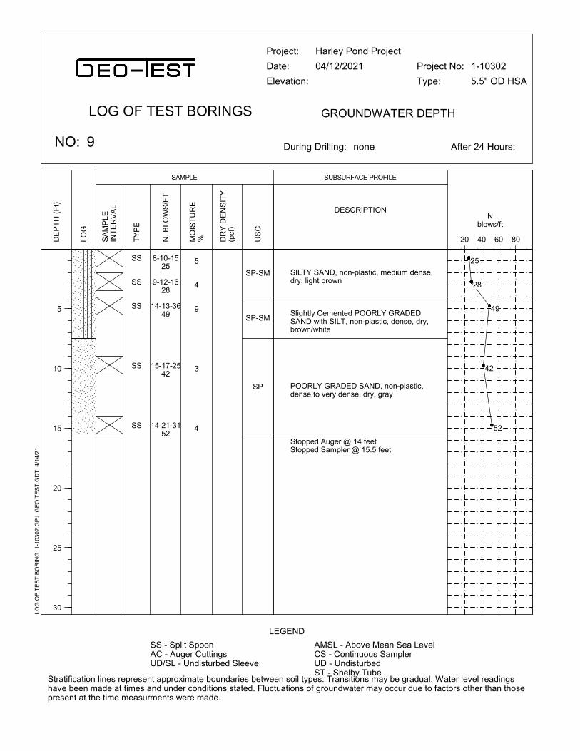
7
12
6
19
23
SS
SS
SS
SS
SS
SILTY SAND, non-plastic, medium dense,dry, light brown
Slightly Cemented POORLY GRADEDSAND with SILT, non-plastic, dense, dry,brown/white
POORLY GRADED SAND, non-plastic,dense to very dense, dry, gray
Stopped Auger @ 14 feetStopped Sampler @ 15.5 feet
5
4
9
3
4
8-10-1525
9-12-1628
14-13-3649
15-17-2542
14-21-3152
SP-SM
SP-SM
SP
Project:
Date:
Elevation:
Harley Pond Project
04/12/2021
During Drilling: none
LEGEND
LOG OF TEST BORINGS
LOG
SA
MP
LEIN
TE
RV
AL
Nblows/ft
20 40 60 80TY
PE
Stratification lines represent approximate boundaries between soil types. Transitions may be gradual. Water level readingshave been made at times and under conditions stated. Fluctuations of groundwater may occur due to factors other than thosepresent at the time measurments were made.
NO: 9
SAMPLE
GROUNDWATER DEPTH
SUBSURFACE PROFILE
Project No:
Type:
1-10302
5.5" OD HSA
DESCRIPTION
DE
PT
H (
Ft)
5
10
15
20
25
30
MO
IST
UR
E% D
RY
DE
NS
ITY
(pcf
)
After 24 Hours:
N.
BLO
WS
/FT
AMSL - Above Mean Sea LevelCS - Continuous SamplerUD - UndisturbedST - Shelby Tube
SS - Split SpoonAC - Auger CuttingsUD/SL - Undisturbed Sleeve
US
C
LOG
OF
TE
ST
BO
RIN
G 1
-103
02.G
PJ
GE
O T
ES
T.G
DT
4/
14/2
1
25
28
49
42
52

SS
SS
SS
SS
SS
SILTY SAND, non-plastic, medium dense toloose, dry, light brown
Moderately Cemented SILTY SAND,non-plastic, very dense, dry, lightbrown/white
POORLY GRADED SAND, non-plastic,medium dense, dry, gray
Stopped Auger @ 14 feetStopped Sampler @ 15.5 feet
4
3
4
5
3
5-6-511
4-3-58
3-8-3341
16-25-3661
11-14-1630
SM
SM
SP
Project:
Date:
Elevation:
Harley Pond Project
04/12/2021
During Drilling: none
LEGEND
LOG OF TEST BORINGS
LOG
SA
MP
LEIN
TE
RV
AL
Nblows/ft
20 40 60 80TY
PE
Stratification lines represent approximate boundaries between soil types. Transitions may be gradual. Water level readingshave been made at times and under conditions stated. Fluctuations of groundwater may occur due to factors other than thosepresent at the time measurments were made.
NO: 10
SAMPLE
GROUNDWATER DEPTH
SUBSURFACE PROFILE
Project No:
Type:
1-10302
5.5" ODHSA
DESCRIPTION
DE
PT
H (
Ft)
5
10
15
20
25
30
MO
IST
UR
E% D
RY
DE
NS
ITY
(pcf
)
After 24 Hours:
N.
BLO
WS
/FT
AMSL - Above Mean Sea LevelCS - Continuous SamplerUD - UndisturbedST - Shelby Tube
SS - Split SpoonAC - Auger CuttingsUD/SL - Undisturbed Sleeve
US
C
LOG
OF
TE
ST
BO
RIN
G 1
-103
02.G
PJ
GE
O T
ES
T.G
DT
4/
14/2
1
11
8
41
61
30

1 1.0 SM 5.2 NP NP 33 74 97 100
1 3.0 4.7
1 5.0 3.2
1 10.0 SM 3.1 NP NP 24 47 79 95 98 100
1 15.0 1.7
1 20.0 1.5
1 25.0 1.2
2 1.0 2.5
2 3.0 2.2
2 5.0 SP-SM 2.3 NP NP 6 20 47 78 90 98 98 100
2 10.0 2.1
2 15.0 3.3
2 20.0 2.8
2 25.0 SP 3.8 NP NP 4 30 84 98 99 100
3 1.0 3.8
3 3.0 SP-SM 1.9 NP NP 11 39 67 88 94 98 100
3 5.0 1.1
3 10.0 1.5
3 15.0 SP 1.5 NP NP 3 12 51 89 96 99 100
4"
Sheet 1 of 4
SIEVE ANALYSISPERCENT PASSING
Project: Harley Pond Project
Location: Rio Rancho, NM
Number: 1-10302
LL = LIQUID LIMITPI = PLASTICITY INDEX
NP = NON PLASTIC or NO VALUE
SUMMARY OF LABORATORY RESULTS
2"1 1/2"1"3/4"1/2"3/8"NO4
NO10
NO40
NO100
NO200
PILL(%)MOIST
UNIFIEDCLASS
DEPTH(FEET)
TESTHOLE
SU
MM
AR
Y O
F L
AB
OR
AT
OR
Y R
ES
ULT
S 1
-103
02.G
PJ
GE
O T
ES
T.G
DT
4/
14/2
1

3 20.0 2.0
3 25.0 1.9
4 1.0 3.8
4 3.0 2.8
4 5.0 SM 3.2 NP NP 15 38 73 93 97 100
4 10.0 1.5
4 15.0 1.7
4 20.0 SP 1.4 NP NP 3 12 49 86 91 93 95 98 100
4 25.0 1.2
5 1.0 SM 3.4 NP NP 18 62 95 100
5 3.0 4.7
5 5.0 2.7
5 10.0 SP-SM 3.2 NP NP 11 29 62 91 97 99 99 100
5 15.0 1.2
5 20.0 1.9
5 25.0 1.9
6 1.0 SM 3.3 NP NP 13 35 66 88 94 98 99 100
6 3.0 1.4
6 5.0 SP 1.7 NP NP 3 12 46 80 87 93 99 100
4"
Sheet 2 of 4
SIEVE ANALYSISPERCENT PASSING
Project: Harley Pond Project
Location: Rio Rancho, NM
Number: 1-10302
LL = LIQUID LIMITPI = PLASTICITY INDEX
NP = NON PLASTIC or NO VALUE
SUMMARY OF LABORATORY RESULTS
2"1 1/2"1"3/4"1/2"3/8"NO4
NO10
NO40
NO100
NO200
PILL(%)MOIST
UNIFIEDCLASS
DEPTH(FEET)
TESTHOLE
SU
MM
AR
Y O
F L
AB
OR
AT
OR
Y R
ES
ULT
S 1
-103
02.G
PJ
GE
O T
ES
T.G
DT
4/
14/2
1

6 10.0 1.4
6 15.0 1.5
7 1.0 2.9
7 3.0 1.4
7 5.0 SP-SM 1.6 NP NP 6 17 38 66 81 89 92 94 100
7 10.0 1.4
7 15.0 1.5
8 1.0 3.1
8 3.0 3.6
8 5.0 SP-SM 2.6 NP NP 9 34 65 88 94 98 98 100
8 10.0 2.1
8 15.0 1.6
9 1.0 4.6
9 3.0 SM 4.0 NP NP 15 54 92 99 100
9 5.0 8.5
9 10.0 SP-SM 3.2 NP NP 9 43 88 97 98 99 99 100
9 15.0 4.0
10 1.0 SM 3.9 NP NP 20 58 93 99 100
10 3.0 3.0
4"
Sheet 3 of 4
SIEVE ANALYSISPERCENT PASSING
Project: Harley Pond Project
Location: Rio Rancho, NM
Number: 1-10302
LL = LIQUID LIMITPI = PLASTICITY INDEX
NP = NON PLASTIC or NO VALUE
SUMMARY OF LABORATORY RESULTS
2"1 1/2"1"3/4"1/2"3/8"NO4
NO10
NO40
NO100
NO200
PILL(%)MOIST
UNIFIEDCLASS
DEPTH(FEET)
TESTHOLE
SU
MM
AR
Y O
F L
AB
OR
AT
OR
Y R
ES
ULT
S 1
-103
02.G
PJ
GE
O T
ES
T.G
DT
4/
14/2
1
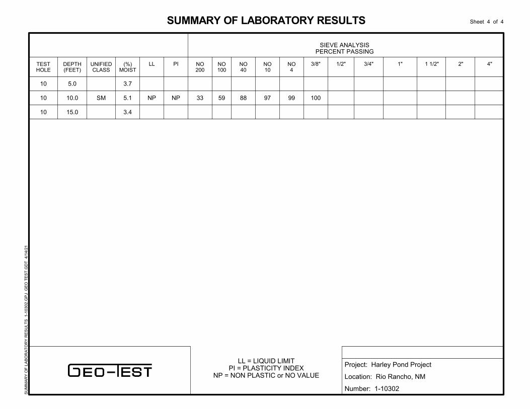
10 5.0 3.7
10 10.0 SM 5.1 NP NP 33 59 88 97 99 100
10 15.0 3.4
4"
Sheet 4 of 4
SIEVE ANALYSISPERCENT PASSING
Project: Harley Pond Project
Location: Rio Rancho, NM
Number: 1-10302
LL = LIQUID LIMITPI = PLASTICITY INDEX
NP = NON PLASTIC or NO VALUE
SUMMARY OF LABORATORY RESULTS
2"1 1/2"1"3/4"1/2"3/8"NO4
NO10
NO40
NO100
NO200
PILL(%)MOIST
UNIFIEDCLASS
DEPTH(FEET)
TESTHOLE
SU
MM
AR
Y O
F L
AB
OR
AT
OR
Y R
ES
ULT
S 1
-103
02.G
PJ
GE
O T
ES
T.G
DT
4/
14/2
1

0
5
10
15
20
25
30
35
40
45
50
55
60
65
70
75
80
85
90
95
100
0.0010.010.1110100
0.118
0.23
0.819
0.266
0.33
2
9.5
19
9.5
12.5
0.091
0.222
0.15
0.12
0.091
0.088
200
COBBLESGRAVEL SAND
PI Cc
GRAIN SIZE DISTRIBUTION
GRAIN SIZE IN MILLIMETERS
PE
RC
EN
T F
INE
R B
Y W
EIG
HT
coarse
3
%Gravel %Sand %Silt %Clay
1
1
2
2
3
100 1403 2
D10
4
fine coarseSILT OR CLAY
4
D30
1.0
10.0
5.0
25.0
3.0
16 20 30 4016 60
fine
HYDROMETERU.S. SIEVE OPENING IN INCHES U.S. SIEVE NUMBERS
SILTY SAND(SM)
SILTY SAND(SM)
POORLY GRADED SAND with SILT(SP-SM)
POORLY GRADED SAND(SP)
POORLY GRADED SAND with SILT(SP-SM)
NP
NP
NP
NP
NP
NP
NP
NP
NP
NP
32.9
23.6
6.0
3.9
10.9
D100 D60
Cu
1
1
2
2
3
LL PL
8.96
3.02
4.51
0.66
0.96
0.60
1.5
medium
6 810 14
Specimen Identification
Specimen Identification
Classification
50
1.0
10.0
5.0
25.0
3.0
3/4 1/23/8
0.0
2.0
10.0
1.0
6.0
67.1
74.4
84.0
95.1
83.1
NP
NP
NP
NP
NP
Project: Harley Pond Project
Location: Rio Rancho, NM
Number: 1-10302
US
GR
AIN
SIZ
E 1
-103
02.G
PJ
GE
O T
ES
T.G
DT
4/1
4/21

0
5
10
15
20
25
30
35
40
45
50
55
60
65
70
75
80
85
90
95
100
0.0010.010.1110100
0.619
0.291
0.679
0.145
0.403
12.5
9.5
25
2
19
0.244
0.118
0.25
0.091
0.155
0.129
0.129
200
COBBLESGRAVEL SAND
PI Cc
GRAIN SIZE DISTRIBUTION
GRAIN SIZE IN MILLIMETERS
PE
RC
EN
T F
INE
R B
Y W
EIG
HT
coarse
3
%Gravel %Sand %Silt %Clay
3
4
4
5
5
100 1403 2
D10
4
fine coarseSILT OR CLAY
4
D30
15.0
5.0
20.0
1.0
10.0
16 20 30 4016 60
fine
HYDROMETERU.S. SIEVE OPENING IN INCHES U.S. SIEVE NUMBERS
POORLY GRADED SAND(SP)
SILTY SAND(SM)
POORLY GRADED SAND(SP)
SILTY SAND(SM)
POORLY GRADED SAND with SILT(SP-SM)
NP
NP
NP
NP
NP
NP
NP
NP
NP
NP
2.7
14.7
2.7
17.8
10.9
D100 D60
Cu
3
4
4
5
5
LL PL
4.79
5.26
5.57
0.74
0.71
0.82
1.5
medium
6 810 14
Specimen Identification
Specimen Identification
Classification
50
15.0
5.0
20.0
1.0
10.0
3/4 1/23/8
4.0
3.0
9.0
0.0
3.0
93.3
82.3
88.3
82.2
86.1
NP
NP
NP
NP
NP
Project: Harley Pond Project
Location: Rio Rancho, NM
Number: 1-10302
US
GR
AIN
SIZ
E 1
-103
02.G
PJ
GE
O T
ES
T.G
DT
4/1
4/21

0
5
10
15
20
25
30
35
40
45
50
55
60
65
70
75
80
85
90
95
100
0.0010.010.1110100
0.351
0.81
1.439
0.363
0.177
19
19
25
19
4.75
0.128
0.262
0.288
0.134
0.098
0.128
0.098
0.077
200
COBBLESGRAVEL SAND
PI Cc
GRAIN SIZE DISTRIBUTION
GRAIN SIZE IN MILLIMETERS
PE
RC
EN
T F
INE
R B
Y W
EIG
HT
coarse
3
%Gravel %Sand %Silt %Clay
6
6
7
8
9
100 1403 2
D10
4
fine coarseSILT OR CLAY
4
D30
1.0
5.0
5.0
5.0
3.0
16 20 30 4016 60
fine
HYDROMETERU.S. SIEVE OPENING IN INCHES U.S. SIEVE NUMBERS
SILTY SAND(SM)
POORLY GRADED SAND(SP)
POORLY GRADED SAND with SILT and GRAVEL(SP-SM)
POORLY GRADED SAND with SILT(SP-SM)
SILTY SAND(SM)
NP
NP
NP
NP
NP
NP
NP
NP
NP
NP
12.6
3.4
5.5
9.0
14.6
D100 D60
Cu
6
6
7
8
9
LL PL
6.34
14.63
4.71
0.66
0.59
0.64
1.5
medium
6 810 14
Specimen Identification
Specimen Identification
Classification
50
1.0
5.0
5.0
5.0
3.0
3/4 1/23/8
6.0
13.0
19.0
6.0
0.0
81.4
83.6
75.5
85.0
85.4
NP
NP
NP
NP
NP
Project: Harley Pond Project
Location: Rio Rancho, NM
Number: 1-10302
US
GR
AIN
SIZ
E 1
-103
02.G
PJ
GE
O T
ES
T.G
DT
4/1
4/21

0
5
10
15
20
25
30
35
40
45
50
55
60
65
70
75
80
85
90
95
100
0.0010.010.1110100
0.223
0.159
0.156
19
4.75
9.5
0.115
0.09
0.077
200
COBBLESGRAVEL SAND
PI Cc
GRAIN SIZE DISTRIBUTION
GRAIN SIZE IN MILLIMETERS
PE
RC
EN
T F
INE
R B
Y W
EIG
HT
coarse
3
%Gravel %Sand %Silt %Clay
9
10
10
100 1403 2
D10
4
fine coarseSILT OR CLAY
4
D30
10.0
1.0
10.0
16 20 30 4016 60
fine
HYDROMETERU.S. SIEVE OPENING IN INCHES U.S. SIEVE NUMBERS
POORLY GRADED SAND with SILT(SP-SM)
SILTY SAND(SM)
SILTY SAND(SM)
NP
NP
NP
NP
NP
NP
8.9
20.0
33.0
D100 D60
Cu
9
10
10
LL PL
2.910.77
1.5
medium
6 810 14
Specimen Identification
Specimen Identification
Classification
50
10.0
1.0
10.0
3/4 1/23/8
2.0
0.0
1.0
89.1
80.0
66.0
NP
NP
NP
Project: Harley Pond Project
Location: Rio Rancho, NM
Number: 1-10302
US
GR
AIN
SIZ
E 1
-103
02.G
PJ
GE
O T
ES
T.G
DT
4/1
4/21

75
80
85
90
95
100
105
110
115
120
125
130
135
140
0 5 10 15 20 25 30 35 40 45
ASTM D1557 Method B
Optimum Water Content
Maximum Dry Density PCF
%
LL PL PI
MOISTURE-DENSITY RELATIONSHIP
TEST RESULTS
Test Method
Embankment Area
DR
Y D
EN
SIT
Y,
pcf
WATER CONTENT, %
ATTERBERG LIMITS
Curves of 100% Saturationfor Specific Gravity Equal to:
2.80
2.70
2.60
10.2
Source of Material
Description of Material
114.2
Project: Harley Pond Project
Location: Rio Rancho, NM
Number: 1-10302
US
CO
MP
AC
TIO
N 1
-103
02.G
PJ
GE
O T
ES
T.G
DT
4/
15/2
1
Silty Sand (SM)

75
80
85
90
95
100
105
110
115
120
125
130
135
140
0 5 10 15 20 25 30 35 40 45
ASTM D1557 Method B
Optimum Water Content
Maximum Dry Density PCF
%
LL PL PI
MOISTURE-DENSITY RELATIONSHIP
TEST RESULTS
Test Method
Embankment Area
DR
Y D
EN
SIT
Y,
pcf
WATER CONTENT, %
ATTERBERG LIMITS
Curves of 100% Saturationfor Specific Gravity Equal to:
2.80
2.70
2.60
8.0
Source of Material
Description of Material
123.6
Project: Harley Pond Project
Location: Rio Rancho, NM
Number: 1-10302
US
CO
MP
AC
TIO
N 1
-103
02.G
PJ
GE
O T
ES
T.G
DT
4/
15/2
1
Poorly Graded Sand (SP)

255.1 grams 422 grams677.1 grams 0.930335 lb6.395 cm 32.11966 cm2
1.27 cm 1.266769 cm2
6.84 cm 0.0394390 cm 219.6985 cm3
0.007759 ft3
238.7 grams 119.9 lb/ft3
216.8 grams 10.1 %108.9 lb/ft3
Time Trial 1 Trial 2 Trial 3Hour 0 0 0Minute 3 3 3Second 10 15 19Total (hr) 0.052778 0.054167 0.055278
h0 65 cm 65 cm 65 cmh1 10 cm 10 cm 10 cm
Head0 71.84 cm 71.84 cm 71.84 cmHead1 16.84 cm 16.84 cm 16.84 cm
Ks (cm/hour) 7.41 cm/hr 7.22 cm/hr 7.08 cm/hr
Ks (cm/sec) 2.06E-03 cm/s 2.01E-03 cm/s 1.97E-03 cm/s
7.24 cm/hr
2.01E-03 cm/s
Saturated Hydraulic Conductivity, Ks:
Saturated Hydraulic Conductivity, Ks:
Moisture Content:
Pressure Head Applied 1psi = 70.34 cm:
Dry Unit Weight:
Can #:Wet Weight:Dry Weight:
Volume of Sample:Volume of Sample:
Unit Weight:
Length of Sample
Weight of Sample:Weight of Sample:
Mold Area:Pipe Area:
Area Factor:
Aparatus Weight Empty:Aparartus Weight + Soil:
Mold Diameter:Pipe Diameter:
Rigid Wall Constant Head Remold Permeability
Remolded to:
Harley Pond Project1-10302Composite of Silty Sand - Embankment Area0 - 15 feetSilty Sand (SM)Approx. 95% of Maximum Density
Project:Job #:
Boring/Location:Sample Depth:
Soil Description:
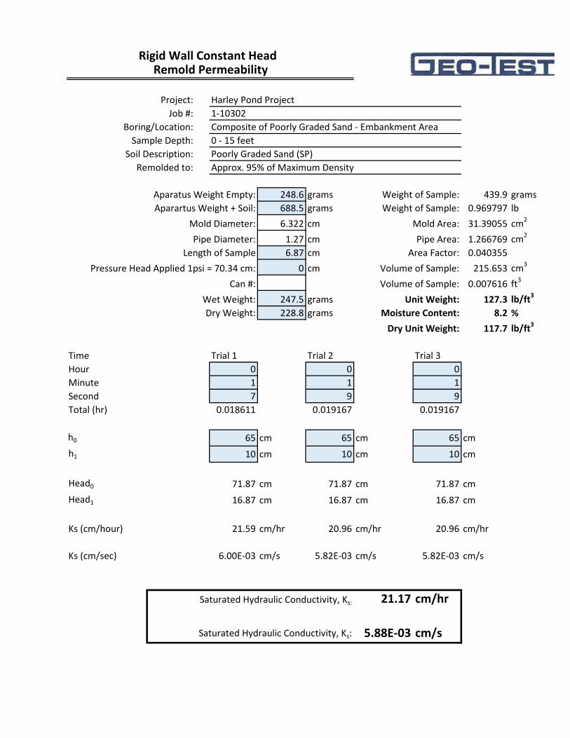
248.6 grams 439.9 grams688.5 grams 0.969797 lb6.322 cm 31.39055 cm2
1.27 cm 1.266769 cm2
6.87 cm 0.0403550 cm 215.653 cm3
0.007616 ft3
247.5 grams 127.3 lb/ft3
228.8 grams 8.2 %117.7 lb/ft3
Time Trial 1 Trial 2 Trial 3Hour 0 0 0Minute 1 1 1Second 7 9 9Total (hr) 0.018611 0.019167 0.019167
h0 65 cm 65 cm 65 cmh1 10 cm 10 cm 10 cm
Head0 71.87 cm 71.87 cm 71.87 cmHead1 16.87 cm 16.87 cm 16.87 cm
Ks (cm/hour) 21.59 cm/hr 20.96 cm/hr 20.96 cm/hr
Ks (cm/sec) 6.00E-03 cm/s 5.82E-03 cm/s 5.82E-03 cm/s
21.17 cm/hr
5.88E-03 cm/s
Rigid Wall Constant Head Remold Permeability
Remolded to:
Harley Pond Project1-10302Composite of Poorly Graded Sand - Embankment Area0 - 15 feetPoorly Graded Sand (SP)Approx. 95% of Maximum Density
Project:Job #:
Boring/Location:Sample Depth:
Soil Description:
Length of Sample
Weight of Sample:Weight of Sample:
Mold Area:Pipe Area:
Area Factor:
Aparatus Weight Empty:Aparartus Weight + Soil:
Mold Diameter:Pipe Diameter:
Saturated Hydraulic Conductivity, Ks:
Saturated Hydraulic Conductivity, Ks:
Moisture Content:
Pressure Head Applied 1psi = 70.34 cm:
Dry Unit Weight:
Can #:Wet Weight:Dry Weight:
Volume of Sample:Volume of Sample:
Unit Weight: