geotechnical report - california energy commission€¦ · report preliminary geotechnical...
TRANSCRIPT

APPENDIX L
S:\06 PROJ\Panoche Energy Center\AFC Appendices\Appendix L Geotechnical Report\1-Coversheet.doc
GEOTECHNICAL REPORT

REPORT PRELIMINARY GEOTECHNICAL INVESTIGATION PROPOSED PANOCHE ENERGY CENTER PROJECT WEST PANOCHE ROAD FRESNO COUNTY, CALIFORNIA JULY 14, 2006 URS JOB NO. 28906975-000040

TABLE OF CONTENT
1.0 INTRODUCTION .................................................................................................................................. 1
2.0 PROJECT DESCRIPTION................................................................................................................... 1 2.1 PROPOSED EQUIPMENT ................................................................................................................. 1 2.2 WEIGHTS AND FOUNDATION DIMENSIONS.............................................................................. 1 2.3 OTHER PROJECT CONSIDERATIONS ........................................................................................... 2
3.0 PURPOSE AND SCOPE OF SERVICES ............................................................................................ 2
4.0 FIELD EXPLORATION AND LABORATORY TESTING.............................................................. 3 4.1 SITE RECONNAISSANCE ................................................................................................................ 3 4.2 FIELD EXPLORATION ..................................................................................................................... 4 4.3 LABORATORY TESTING................................................................................................................. 4
5.0 SITE GEOLOGY ................................................................................................................................... 4 5.1 REGIONAL GEOLOGY..................................................................................................................... 4 5.2 GEOLOGIC SOIL CONDITIONS ...................................................................................................... 5 5.3 GROUNDWATER CONDITIONS ..................................................................................................... 5 5.4 GEOLOGIC AND SEISMIC HAZARDS............................................................................................ 5
5.4.1 Primary Ground Rupture ............................................................................................................. 5 5.4.2 Ground Shaking ........................................................................................................................... 6 5.4.3 Liquefaction and Seismic-Induced Settlement.............................................................................. 7 5.4.4 Subsidence ................................................................................................................................... 7 5.4.5 Other Geologic and Seismic Hazards .......................................................................................... 8
6.0 SURFACE AND SUBSURFACE CONDITIONS................................................................................ 8 6.1 SURFACE CONDITIONS .................................................................................................................. 8 6.2 SUBSURFACE CONDITIONS........................................................................................................... 9 6.3 DESIGN GROUNDWATER LEVELS ............................................................................................... 9
7.0 DISCUSSION AND RECOMMENDATIONS .................................................................................... 9 7.1 FOUNDATION CONSIDERATIONS ................................................................................................ 9
7.1.1 Key Geotechnical Issues .............................................................................................................. 9 7.1.2 Site Improvement Options for Mat Foundations.......................................................................... 9 7.1.3 Alternative Deep Foundation Schemes ...................................................................................... 10
7.2 EARTHWORK.................................................................................................................................. 10 7.2.1 Compaction Criteria .................................................................................................................. 10 7.2.2 On-Site Sources and Import Materials Criteria......................................................................... 11 7.2.3 Temporary Excavations ............................................................................................................. 11 7.2.4 Permanent Cut and Fill Slopes .................................................................................................. 12
7.3 TEMPORARY SHORING ................................................................................................................ 12 7.4 LATERAL EARTH PRESSURES..................................................................................................... 13

7.5 MAT FOUNDATIONS WITH ENGINEERED FILL ....................................................................... 14 7.5.1 Overexcavation and Recompaction............................................................................................ 14 7.5.2 Bearing Pressures and Anticipated Settlements......................................................................... 14 7.5.3 Structural Design of Mat Foundation ........................................................................................ 15
7.6 MAT FOUNDATIONS WITH IN-SITU SOIL IMPROVEMENT.................................................... 16 7.7 SPREAD FOOTINGS (LIGHTY LOADED STRUCTURES)......................................................... 16 7.8 RESISTANCE TO LATERAL LOADS ............................................................................................ 17 7.9 DRIVEN PILES................................................................................................................................. 17
7.9.1 General ...................................................................................................................................... 17 7.9.2 Axial Capacities ......................................................................................................................... 17 7.9.3 Lateral Capacities...................................................................................................................... 18
7.10 CAST-IN-DRILLED-HOLE PILES FOR LIGHT POLES.............................................................. 19 7.11 PAVEMENTS AND SIDEWALKS ................................................................................................ 20 7.12 PAVEMENT STRUCTURAL SECTIONS ..................................................................................... 20 7.13 SEISMIC PARAMETERS............................................................................................................... 21
7.13.1 Probabilistic Seismic Hazard Assessment................................................................................ 21 7.13.2 California Building Code (2001 CBC)..................................................................................... 22
7.14 SURFACE DRAINAGE.................................................................................................................. 22 8.0 DESIGN REVIEW ............................................................................................................................. 22
9.0 CONSTRUCTION MONITORING ................................................................................................... 23
10.0 LIMITATIONS................................................................................................................................... 23
11.0 REFERENCES ................................................................................................................................... 25

1
1.0 INTRODUCTION This report presents the results of a geotechnical investigation performed by URS Corporation (URS) for the proposed Panoche Energy Center Project (Project) in Fresno County, California. The Project site covers approximately 12.8 acres, located on the south side of West Panoche Road, approximately 2 miles east of the intersection of Panoche Road and Interstate Highway 5. The location of the site relative to existing topographic features is shown in the Vicinity Map, Figure 1. This report includes our geotechnical recommendations for design and construction of the proposed Project. Conclusions and recommendations presented in this report are based on subsurface conditions encountered at the locations of our explorations and our experience on similar projects. Soil and groundwater data obtained during our field explorations were observed and interpreted at our boring locations only. Conditions may vary between boring locations, and should not be extrapolated to other areas without our prior review.
2.0 PROJECT DESCRIPTION 2.1 PROPOSED EQUIPMENT We understand that it is proposed to install a 400 megawatt electrical generating facility at the site. The generating facility will consist of four (4) General Electric LMS100 natural gas-fired combustion turbine generators (CTGs), a selective catalytic reduction (SCR) and an oxidation catalyst. Auxiliary equipment will include inlet air filters with evaporative coolers, turbine compressor section inter-cooler, mechanical draft cooling tower, circulating water pumps, water treatment equipment, natural gas compressors, generator step-up and auxiliary transformers, and water storage tanks. 2.2 WEIGHTS AND FOUNDATION DIMENSIONS We understand that concrete mat foundations will be used primarily to facilitate efficient interaction between critical equipment components. Weights and dimensions of major components as provided by the project civil/structural engineer (Bibb & Associates) are as follows:
2
Description Length (Feet)
Width (Feet)
Weight (Pounds)
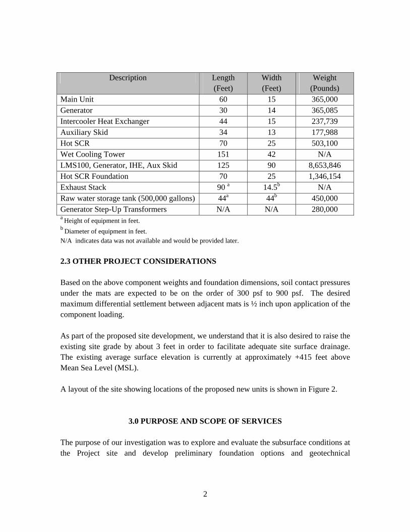
Main Unit 60 15 365,000 Generator 30 14 365,085 Intercooler Heat Exchanger 44 15 237,739 Auxiliary Skid 34 13 177,988 Hot SCR 70 25 503,100 Wet Cooling Tower 151 42 N/A LMS100, Generator, IHE, Aux Skid 125 90 8,653,846 Hot SCR Foundation 70 25 1,346,154 Exhaust Stack 90 a 14.5b N/A Raw water storage tank (500,000 gallons) 44a 44b 450,000 Generator Step-Up Transformers N/A N/A 280,000 a Height of equipment in feet. b Diameter of equipment in feet. N/A indicates data was not available and would be provided later. 2.3 OTHER PROJECT CONSIDERATIONS Based on the above component weights and foundation dimensions, soil contact pressures under the mats are expected to be on the order of 300 psf to 900 psf. The desired maximum differential settlement between adjacent mats is ½ inch upon application of the component loading. As part of the proposed site development, we understand that it is also desired to raise the existing site grade by about 3 feet in order to facilitate adequate site surface drainage. The existing average surface elevation is currently at approximately +415 feet above Mean Sea Level (MSL). A layout of the site showing locations of the proposed new units is shown in Figure 2.
3.0 PURPOSE AND SCOPE OF SERVICES The purpose of our investigation was to explore and evaluate the subsurface conditions at the Project site and develop preliminary foundation options and geotechnical

3
recommendations for design and construction of the Project. The scope of our services included performing the following tasks:
• Review of previous geotechnical and geologic data pertinent to the project site;
• Site reconnaissance to review existing site features and proposed boring locations;
• A field exploration program involving drilling and sampling of twenty (20) borings;
• Laboratory testing of selected soil samples obtained from the borings to evaluate in-situ moisture/density, index properties, shear strength, and other pertinent properties of the soils;
• Provide the zone factor, Z, and soil profile type, S, and near-surface factors per the 2001 California Building Code (CBC);
• Evaluate the potential for liquefaction and seismic-induced settlements; • Engineering analyses to develop geotechnical recommendations for design
and construction of the project; and • Preparation of this engineering report.
4.0 FIELD EXPLORATION AND LABORATORY TESTING 4.1 SITE RECONNAISSANCE Prior to initiating any fieldwork URS personnel performed a reconnaissance on May 31, 2006 to observe the existing site conditions. In accordance with State regulations, URS contacted Underground Service Alert (USA) of Northern California regarding subsurface utility clearance at the site. USA responded by notifying various agencies who identified known underground utilities and subsurface obstructions on the property by marking the ground surface with color-coded paint. Boring locations were established at the site by URS land surveyors on June 12, 2006. Borings were located primarily within the footprints of proposed major units and equipment. As necessary, borings were relocated in the field depending upon access conditions. Coordinates of the final boring locations are shown on the logs of borings.

4
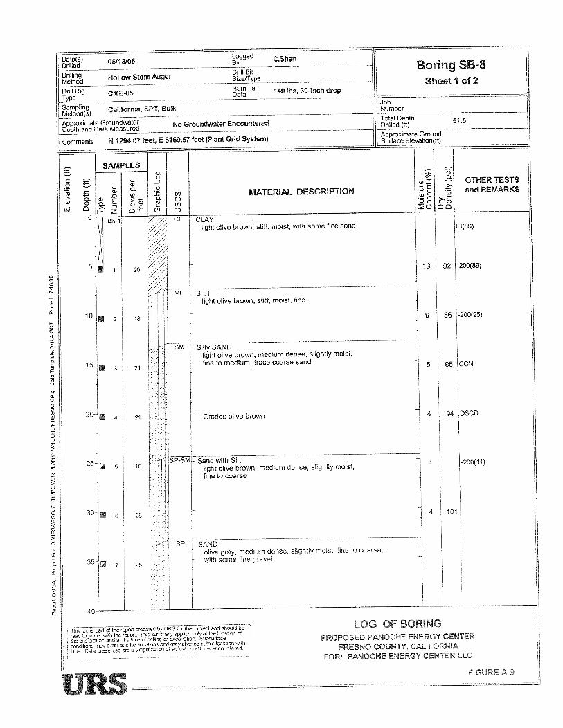
4.2 FIELD EXPLORATION A field exploration program was initiated on June 12 and completed on June 16, 2006 under the technical supervision of a representative from our Los Angeles office. Exploratory borings were drilled using a truck-mounted drilling rig equipped with 8-inch diameter hollow stem augers. Twenty (20) borings (Borings SB-1 through SB-20) were advanced to depths ranging between 30 feet and 65 feet below existing ground surface. Relatively undisturbed soil samples were obtained using a California Type-U Sampler. Standard Penetration Tests (per ASTM D-1586) were performed at selected depths for seismic-induced settlement evaluation. Upon completion of the drilling activities, the boreholes were backfilled with soil cuttings generated during drilling. The locations of the borings are shown in Figure 2. A detailed description of the field exploration program, including boring logs, key to the logs of borings and other pertinent information, is presented in Appendix A. 4.3 LABORATORY TESTING Soil samples obtained from the borings were packaged and sealed in the field to prevent moisture loss and disturbance and transported to our Los Angeles laboratory where they were further examined and classified. Index and strength tests were performed on selected soil samples in accordance with ASTM standards. A detailed description of the laboratory testing program is presented in Appendix B.
5.0 SITE GEOLOGY 5.1 REGIONAL GEOLOGY The Project site is located in the western San Joaquin Valley, which is part of the Central Valley, also referred to as the Great Valley geomorphic province. The Central Valley comprises about 20,000 square miles and extends from near Red Bluff on the north to near Bakersfield on the south. The most extensive geomorphic units in the province include dissected uplands, low alluvial plains and fans, river flood plains and channels, and overflow lands and lake bottoms. The valley represents the alluvial, flood, and delta plains of two major rivers (the Sacramento and San Joaquin Rivers) and their tributaries.
5
5.2 GEOLOGIC SOIL CONDITIONS The Project site is located southeast of Panoche Creek on the Panoche Creek alluvial fan at an elevation of about +415 feet MSL. Published geologic mapping of the site indicates that geologic materials exposed within a two-mile radius of the site comprise primarily of surficial sediments. The site is located within an area mapped as Quaternary age alluvium composed of clays, silts and sands. As observed in our exploratory borings, the underlying site materials consist of a thin blanket of possible artificial fill overlying recent alluvium. These alluvial deposits primarily comprise clays and silts. 5.3 GROUNDWATER CONDITIONS The Project Site is located in the Westside Subbasin of the San Joaquin Valley Groundwater Basin. The Westside Subbasin consists mainly of the lands in the Westlands Water District. Groundwater was not encountered in any of the borings drilled during our subsurface investigation to the maximum depths explored, 65 feet. Depth to groundwater in the vicinity of the site is estimated to occur at a depth of about 195 feet ground surface. 5.4 GEOLOGIC AND SEISMIC HAZARDS Geologic and seismic hazards are those hazards that could impact a site due to the surrounding geologic and seismic conditions. Geologic hazards include landsliding, erosion, subsidence, volcanic eruptions, and poor soil conditions. Seismic hazards include phenomena that occur during an earthquake such as ground shaking, ground rupture, and liquefaction. Our assessment of these hazards was based on guidelines established by the California Geological Survey (1997) and as outlined in CDMG Special Publication 117 (1999). 5.4.1 Primary Ground Rupture Primary ground rupture is defined as the surface displacement which occurs along the surface trace of the causative fault during an earthquake. According to the California Geological Survey, the site is not currently located within an Alquist-Priolo Earthquake Fault Zone. Based on our review of available geologic data, no other surface traces of active

6
faults pass through the site. Therefore, the potential for primary ground rupture within the project site during a seismic event is low. 5.4.2 Ground Shaking The site may experience strong seismic shaking in the future. The California Geological Survey (CGS) defines an active fault as one which has experienced surface rupture within the last 11,000 years (Holocene time). Potentially active faults have shown displacement within the last 1.6 million years (Quaternary age). “Inactive faults” show no evidence of movement in historic or recent geologic time, suggesting that the faults are dormant (Fresno County, 2000). The nearest potential sources of strong seismic shaking (as designated by the State of California) include: • Ortigalita Fault Zone: The Ortigalita fault zone is approximately 50 miles long,
originating near Crow Creek in western Stanislaus County and extending southeast to a few miles north of Panoche in western Fresno County. Most of the fault is considered active due to displacement during Holocene time (Fresno County, 2000). The Ortigalita Fault is a major Holocene dextral strike-slip fault in the central Coast Ranges that is an eastern part of the larger San Andreas fault system. The Ortigalita fault zone is about 19.4 miles from the site at its closest point.
• The San Andreas Fault Zone: The San Andreas Fault is considered active and is of
primary concern in evaluating seismic hazards throughout western Fresno County (Fresno County, 2000). The 1,100 kilometer long San Andreas fault zone is the principal element of the San Andreas fault system, a network of faults with predominantly dextral strike-slip displacement that collectively accommodates the majority of relative north-south motion between the North American and Pacific plates. The closest segment of the San Andreas Fault is located approximately 28.2 km west and southwest of the site.
• Nunez Fault: The Nunez Fault is located approximately six to seven miles northwest
of Coalinga and is about 30 miles from the site at its closest point. The fault is about 4.2 kilometers long and is considered active based on surface rupture associated with the 1983 Coalinga earthquake.
• The Great Valley Thrust Faults: The Great Valley Thrust Faults have been divided
into at least 14 segments extending over 300 miles in cumulative length based on

7
geomorphic interpretation of the range front (USGS, 2006a). The closest Great Valley thrust fault is about 5.3 miles from the site at its closest point.
5.4.3 Liquefaction and Seismic-Induced Settlement Liquefaction is a phenomenon whereby loose, saturated, granular soils lose their inherent shear strength due to excess pore water pressure build-up such as that generated during repeated cyclic loading from an earthquake. A low relative density of the granular materials, shallow ground-water table, long duration and high acceleration of seismic shaking are some of the factors favorable to cause liquefaction. Presence of predominantly cohesive or fine-grained materials and/or absence of saturated conditions can preclude liquefaction. Due to absence of groundwater at the site, the potential for liquefaction to occur and impact the site is low. Although liquefaction is not expected to pose a hazard to the site, the presence of loose, unsaturated granular soil layers could result in some seismic-induced settlement that would need to be taken into account during foundation design. The potential for seismic-induced settlement was evaluated using the SPT data from our current exploratory borings and the results of the laboratory tests. The analysis was performed using the LIQUEFY program based on the simplified procedure outlined in Youd and Idriss (2001). A peak ground acceleration of 0.48g was used in the analysis (see Section 7.13 of this report) Based on the results of the analyses, some seismic-induced settlement could occur within the loose to medium dense sandy and silty layers in the upper 40 feet based on a DLE event, resulting in settlement of about 2 inches within the susceptible soil layers. 5.4.4 Subsidence Subsidence occurs when a large portion of land is displaced vertically, usually due to the withdrawal of groundwater, oil, or natural gas. By the mid-1960’s withdrawal of groundwater for agriculture is known to have caused up to 26 feet of subsidence in some areas within the San Joaquin Valley. Subsidence rates reportedly increased until the mid-1950’s when the maximum observed rate was 1.8 feet per year (Bull, 1975). Beginning in mid-1960’s, surface water imported via the California Aqueduct began to replace groundwater as the primary source of irrigation supply in the area south of Mendota (Gilliom et al., 1989; Belitz and Heimes, 1990). By 1983, land subsidence due to groundwater withdrawal appeared to have slowed considerably or stopped in most of the San Joaquin Valley (Ireland, 1986).

8
5.4.5 Other Geologic and Seismic Hazards The CGS has not developed any landslide hazard maps for Fresno County. However, the existing topography at the site does not provide sufficient relief that would cause concern from landslides. Therefore, landsliding is not anticipated to pose a hazard to the site. Also, by being relatively flat, the proposed site should not be readily susceptible to erosion. No centers of potential volcanic activity occur within hundreds of miles of the site. Volcanic hazards, such as lava flows and ash falls, are therefore not anticipated to present a hazard to the proposed site. Other seismic hazards include tsunamis, seiches, and differential soil settlement. A tsunami is a great sea wave (commonly called a tidal wave) produced by a significant undersea disturbance such as tectonic displacement of the sea floor associated with large, shallow earthquakes. A seiche is an oscillation of a body of water in an enclosed or semi-enclosed basin (such as a reservoir, harbor, lake or storage tank) resulting from earthquakes or other large environmental disturbances. The potential for tsunamis and seiches at the Project Site is nil to low due to the absence of oceans, lakes, or large bodies of water in the immediate area. Differential soil settlement occurs when significantly different densities and strengths of soil abut each other and seismic shaking causes one type of soil to settle more than the other. Based on our current field explorations, the site appears to be underlain by relatively uniform soil conditions that should not be prone to significant differential settlement under earthquake loading conditions.
6.0 SURFACE AND SUBSURFACE CONDITIONS 6.1 SURFACE CONDITIONS The proposed Project site occupies approximately 12.8 acres, and is generally flat at an average elevation of approximately +415 feet MSL. The site currently in agricultural production with numerous rows of pomegranate trees. Surrounding areas are predominantly used for agriculture with two existing power generation facilities nearby. Anticipated subsurface utilities present below the surface consist mainly of irrigation and water supply lines for agricultural purposes. Overhead power lines are present in the vicinity but do not cross over the site boundaries.

9
6.2 SUBSURFACE CONDITIONS The subsurface soils at the site generally consist of interbedded clays, silts and sands to the maximum depth explored of 65 feet below the existing ground surface. In the upper 40 feet, the granular (sandy) soils were generally loose to medium dense in consistency and the fine-grained soils (clays and silts) were generally medium stiff to stiff. Below 40 feet, the soils dense soils were encountered, grading denser to the maximum depth explored in the borings (65 feet). The fine-grained soils are relatively compressible and moderately expansive. 6.3 DESIGN GROUNDWATER LEVELS Groundwater was not encountered in any of the borings drilled during the current investigation. As discussed in Section 5.3, depth to groundwater is expected to be about 195 feet below existing ground surface at the site. Therefore, groundwater is not expected to have a significant impact to the design and construction of this project.
7.0 DISCUSSION AND RECOMMENDATIONS 7.1 FOUNDATION CONSIDERATIONS 7.1.1 Key Geotechnical Issues The upper 40 feet of the site consists of loose to medium dense granular soils and compressible fine-grained soils, which are in turn underlain by dense to very dense soils to the maximum depth explored of 65 feet. Due to the loose and compressible consistency of the upper soils, equipment supported on shallow (mat) foundations are expected to experience significant static settlements. In addition, the loose sandy deposits are susceptible to seismic-induced settlement from a design earthquake. 7.1.2 Site Improvement Options for Mat Foundations We understand that mat foundations are being considered for support the major units. However, in order to limit total and differential settlements of the mat foundations, improvement of the upper loose and compressible soils will be necessary. A common

10
method of improvement would be direct overexcavation and recompaction of the unsuitable soils. This is discussed in more detail in Section 7.5. In lieu of soil removal and recompaction, selective replacement or in-situ improvement of the loose to medium dense soils using gravel or stone columns, or deep soil-cement mixing, may be viable alternatives for providing improvement under the mats. This site improvement is discussed further in Section 7.6 of this report. 7.1.3 Alternative Deep Foundation Schemes Alternatively, deep foundations established in the underlying dense alluvial deposits should also provide adequate support for the different individual equipment units and mitigation for both static and seismic induced settlements. The use of deep foundations would preclude the need for improvement of the on-site soils. Conventional driven, pre-cast concrete piles may be considered for support of the major, heavy units. Other deep foundation options such as cast-in-drilled-hole (CIDH) piles and auger-cast piles may be considered and recommendations can be provided if needed. Preliminary design criteria for the driven piles are provided in Section 7.9 of this report. Specific recommendations for site earthwork, pavement, foundation design, and construction monitoring are provided below. 7.2 EARTHWORK 7.2.1 Compaction Criteria The compaction criteria will depend on the specific loading conditions anticipated. In general, all fills and backfills should be compacted to the minimum requirements of the California Building Code unless specifically recommended. Fills and backfills should be placed in loose lifts not exceeding 8 inches in thickness and moisture conditioned as required to achieve near-optimum or above moisture content. All fills and backfills should be compacted using mechanical compaction equipment. All fills and backfills providing structural support should be compacted to at least 95 percent of the maximum dry density per ASTM D-1557. This should include all areal fills placed to raise the site grade and fills and backfills providing passive resistance for footings and pile caps, as well as support for pavements and slabs-on-grade.

11
Secondary and non-structural fills may be compacted to at least 90 percent per ASTM D1557. 7.2.2 On-Site Sources and Import Materials Criteria Most of the materials to be excavated in order to satisfy any one of the above described foundation options would comprise predominantly sandy and clayey soils, depending upon the site locations. The sandy soils may be reused as engineered fill from a geotechnical stand-point. Predominately clayey soils should be blended with the sandy soils in order to enhance the soil compaction characteristics. The geotechnical engineer should be present to review the types of materials encountered in the excavations in order to confirm their re-usability. All imported fill and backfill soils should be predominantly granular, non-expansive, less than 3 inches in any dimension and be free of organic and inorganic debris. All fill and backfill materials should be observed and tested by the geotechnical engineer prior to their use in order to evaluate their suitability. Fill materials with any appreciable amount of fines (greater than 35 percent passing the #200 sieve) should be observed and tested by the geotechnical engineer prior to their use. 7.2.3 Temporary Excavations All excavations should comply with the current California and Federal OSHA requirements, as applicable. All cuts greater than 5 feet in depth should be sloped and/or shored. Temporary excavations should be no steeper than 1(h):1(v), up to a maximum depth of 10 feet below surrounding grade. Flatter slopes will be required if clean and/or loose sandy soils are encountered along the slope face. Steeper cuts may be utilized for cuts less than 5 feet deep depending on the strength and homogeneity of the soils as observed in the field. The following table summarizes the excavation slopes for various excavation depths.
Excavation Depth (Feet) Required Excavation Support
Less than 5 Vertical 5 to 10 1:1 slopes Over 10 Shoring Required
No excavation is allowed within the influence zone of existing footings unless the footings are properly underpinned. The influence zone of the existing footings may be

12
assumed to be below a 45-degree line projected down from the bottom edge of the footing. If removal of unsuitable soils within the influence zone described above becomes necessary, existing footings will need to be underpinned. Specific recommendation for underpinning can be provided on a case-by-case basis, if needed. During wet weather, runoff water should be prevented from entering the excavation, and collected and disposed of outside the construction limits. To prevent runoff from adjacent areas from entering the excavation, a perimeter berm should be constructed at the top of the slope. Heavy construction equipment, building materials, excavated soil stockpiles and vehicle traffic should not be allowed near the top of the slope within a horizontal distance equal to the depth of the excavation. 7.2.4 Permanent Cut and Fill Slopes All permanent fill and cut slopes should be constructed at 2(h): 1(v) or flatter. Benching should be performed during construction of all fill slopes for existing ground surface that is at 5(h): 1(v) or steeper. All fill slopes should be compacted to 95 percent of the maximum dry density and in accordance with applicable grading codes. 7.3 TEMPORARY SHORING If the available space will not permit sloping or benching of the excavations, a temporary shoring system will be required. It is assumed that the temporary shoring will be in place for a few weeks only. Shoring systems typically consist of a soldier pile and lagging retention system; either tied-back, internally braced, or cantilevered. On a preliminary basis, typical soldier piles consist of steel H-sections installed in predrilled holes. The holes should be backfilled below the planned bottom of the excavation with structural concrete and with lean concrete above. Horizontal spacing between soldier piles should be limited to about 8 feet. Treated timber lagging may be required in sandy zones. Any space between the lagging and excavation should be filled with lean concrete with provisions for weepholes to reduce the potential for buildup of hydrostatic pressure. The temporary shoring system should be designed to resist lateral earth pressures plus additional horizontal pressures imposed by foundations of adjacent structures.

13
Temporary cantilevered shoring should be designed for a triangular load distribution equivalent to the pressure exerted by a fluid weighing 35 pounds per cubic foot (pcf). For an areal surcharge placed adjacent to the shoring, an equivalent, horizontal (rectangular) pressure equivalent to thirty (30) percent of the surcharge may be assumed to act along the entire length of the shoring. Soldier piles must extend below the excavation bottom to provide lateral resistance by passive soil pressure. Allowable passive pressures may be taken as equivalent to the pressure exerted by a fluid weighing 250 pcf in alluvium to a maximum value of 2,500 psf. To account for three-dimensional effects, the lateral pressure may be assumed to act on an area twice the pile width. The above values for passive pressure incorporate a factor of safety of at least 1.5. For lagging design, it is customary to account for about fifty percent of the basic earth pressure for temporary conditions. For this purpose a uniform horizontal pressure (rectangular distribution) of 10H psf may be assumed for lagging design. The above design recommendations do not include any hydrostatic pressure. It is assumed that drainage will be provided through cracks in the lagging. 7.4 LATERAL EARTH PRESSURES Walls should be designed to resist the earth pressure exerted by the retained soils, plus any additional lateral forces that will be applied to the walls due to surface loads placed at, or near the top, those due to potential ground water build-up and seismic loads. Adequate provisions are required to counteract the effects of hydrostatic pressure, as recommended previously. Free-draining backfill should be used behind portions of walls above the design ground-water level. Provisions should be made to collect and dispose of water that may accumulate behind the walls. The at-rest earth pressure against walls with a level-backfill that are restrained at the top can be taken as equivalent to the pressure exerted by a fluid weighing 60 pcf. Fifty percent of any uniform areal surcharge placed at the top of a restrained wall will act as a uniform horizontal pressure over the entire height of the wall. Walls that are not restrained at the top may be designed for an active earth pressure developed by an equivalent fluid weighing 35 pcf. Thirty percent of any uniform surcharge will act as a uniform horizontal pressure over the entire height of the wall.

14
The above lateral earth pressures do not include any hydrostatic pressure. Therefore, wall backfill should be free draining and provisions should be made to collect and dispose of water that may accumulate behind the walls. Light equipment should be used during backfill compaction to avoid possible overstressing of walls. 7.5 MAT FOUNDATIONS WITH ENGINEERED FILL 7.5.1 Overexcavation and Recompaction Mat foundations established in engineered fill prepared in accordance with the preceding recommendations may be considered for support for the project, provided the estimated settlements can be tolerated. Conventional removal and recompaction of the upper soils may be performed for this purpose. On a preliminary basis, and for estimating purposes, we have performed engineering analysis to provide design and construction recommendations for a nominal 10 feet of removal and recompaction under the mat foundations. The proposed site grading (additional 3 feet of fill) may be taken into account in the nominal fill thickness. The engineered fill should extend a minimum 10 feet beyond the edge of the mat, or equal to the thickness of fill under the mat whichever is greater. Mats should be embedded a minimum of 12 inches below the lowest finished adjacent grade. 7.5.2 Bearing Pressures and Anticipated Settlements The allowable bearing pressure for the mat foundation will be governed by the allowable settlement. The following table presents the bearing pressures versus predicted settlements (static) for a mat foundation based on the above nominal site preparation constraints (ie. 10 feet of improvement).
Soil Bearing Pressure (psf)
Predicted Static Settlement (inches)
500 2 1000 4
A one-third increase to the above bearing values may be assumed when considering the effects of temporary wind or seismic loads. The bearing values given above are net values.
15
The predicted settlements indicated above are total static settlements. In addition to the anticipated settlements, seismic-induced settlements as discussed in Section 5.4.3 should be accounted for. Maximum differential settlement between adjacent, similarly loaded mats is expected to be about half of the total predicted settlement. As discussed above, maximum settlement of mat foundations when supported on a minimum 10 feet of engineered fill is estimated to be on the order of 4 inches. In order to reduce the magnitude of settlement, it follows that additional overexcavation and recompaction beyond 10 feet would be required. 7.5.3 Structural Design of Mat Foundation For further analysis of a mat foundation scheme, the preceding bearing values and predicted settlements can be used in the rigid mat method, a conventional method for structural design of a mat foundation. Another common design method is the approximate flexible method (American Concrete Institute Committee 336) in which the foundation soil is modeled as an infinite number of elastic springs. The elastic spring constant is referred to as the modulus of subgrade reaction (k). For large foundations such as a mat, the k value is also a function of the size of the foundation. The following equation may be used to estimate the k value (in units of pounds per cubic inch, pci) for a mat with dimensions of B (width) by L (length): k = ks (m + 0.5)
1.5m where:
ks = 5 to 10 pci m = ratio of L/B For a more refined analysis/structural design of mat foundations, there are other more rigorous discrete-element methods such as the finite-difference and the finite-element methods. These methods utilize advanced numerical modeling techniques by dividing the mat into grid elements and predicting the behavior of the soil and structure under loading (soil-structure-interaction, SSI) for each element. URS has these capabilities and upon request by the owner, can assist the structural engineer to rapidly evaluate the sensitivity of a design to extreme soil or loading conditions.
16
7.6 MAT FOUNDATIONS WITH IN-SITU SOIL IMPROVEMENT If the overexcavation and recompaction option discussed in Section 7.5 proves to be unfeasible, in-situ improvement of the unsuitable soils may be considered. One technique, known as vibro-replacement or vibro-compaction (or stone columns), involves use of specially designed vibratory equipment to direct compactive energy at the required improvement depths. As the vibratory device is withdrawn from the ground, the resulting void is filled with sand, gravel or stone, and then re-vibrated to ensure densification effort throughout the penetration depth. Another similar technique involves deep soil-cement mixing, where in-situ mixed soil-cement columns are installed by approximately 4 to 5 foot diameter blades which are inserted into the ground to blend the in-situ materials. The disturbed cylinder of soil is mixed with cement and water to create a homogenous column of soil-cement. In both cases, the stone or soil-cement columns are typically installed in a grid pattern directly under the footprint of the mat. For these types of in-situ improvement, it is customary to leave specific equipment and procedural specifications to a specialty contractor to achieve the specified project criteria in a performance specification. 7.7 SPREAD FOOTINGS (LIGHTY LOADED STRUCTURES) Lightly-loaded (about 10 to 25 kips), non-settlement sensitive (i.e., not sensitive to the magnitudes of static and seismic-induced settlements), and isolated units may be supported on conventional spread footings established on a minimum 3 feet of compacted engineered fill. The final thickness of engineered fill would depend upon the actual depths of removal of uncertified fills during site preparation. The limits of engineered fill should extend at least 3 feet beyond the edges of the footings or equal to the depth of improvement under the footing, whichever is greater. Footings should be a minimum of 2 feet wide and established at a minimum depth of 2 feet below the lowest adjacent final grade. An allowable bearing pressure of 1,500 pounds per square foot (psf) may be used for spread footings with the above minimum dimensions. The allowable bearing pressure is a net value. Therefore, the weight of the foundation and the backfill over the footing may be neglected when computing dead loads. The bearing pressure applies to dead plus live loads and includes a calculated

17
factor of safety of at least 3. The allowable bearing pressure value may be increased by one-third for short-term loading due to wind or seismic forces. Total static settlements of individual, lightly loaded spread footings will vary depending on the width of the footing and the actual load supported. Total static settlements of footings, designed and constructed in accordance with the preceding recommendations are estimated to be on the order of 1 inch or less. 7.8 RESISTANCE TO LATERAL LOADS Resistance to lateral loads may be provided by frictional resistance between concrete mats and the underlying soils and by passive soil pressure against the sides of the mats. The coefficient of friction between the concrete foundations and the underlying soils may be taken as 0.4. Passive pressure available in compacted backfill may be taken as equivalent to the pressure exerted by a fluid weighing 250 pounds per cubic foot (pcf) to a maximum 2,500 psf. A one-third increase in the passive value may be used for temporary wind or seismic loads. The above-recommended values include a factor of safety of at least 1.5; therefore, frictional and passive resistances may be used in combination without reduction. 7.9 DRIVEN PILES 7.9.1 General Pre-stressed, concrete piles (12-inch or 14-inch square) may be considered for support of the heavy, settlement sensitive equipment, as appropriate. The piles should be driven through the upper loose to medium dense soils into the underlying dense to very dense sands to obtain the required load-bearing capacities. It is anticipated that the piles would need to be driven to depths of about 50 to 65 feet below the pile cap in order to achieve adequate axial capacities. 7.9.2 Axial Capacities The piles should be driven with a hammer delivering, at a minimum, energy on the order of 50,000 foot-pounds per blow. For preliminary estimating purposes only, piles should be driven to a refusal criterion of at least 40 continuous blows for the last 3-foot of penetration. The above refusal criterion is intended to result in allowable downward and upward axial pile capacities as shown in the table below.

18
Pile Width (Inches)
Allowable Downward Capacity
Allowable Upward Capacity
12 100 kips 30 kips 14 150 kips 40 kips
The above estimates of axial capacities are based on conventional analyses performed using the methods outlined in Chapter 5 of the Design Manual 7.02 prepared by Naval Facilities Engineering Command (NavFac) for displacement piles. The allowable downward and upward capacities include a factor of safety of at least 2.0. The allowable downward capacities have considered the anticipated effects of some down-drag generated from seismically-induced settlement of the upper strata, including the identified liquefiable layer. The allowable downward and upward capacities may be increased by 33 percent to account for temporary loads such as those from wind or earthquakes. To avoid interference with adjacent piles, and to minimize group effects we recommend that the piles be spaced a minimum of 3 pile widths, center-to-center. For this minimum spacing, it will not be necessary to reduce axial capacities for group action. Settlements of the piles are expected to be less than one inch, including elastic compression of the piles under the design loads. The pile-driving rig should be equipped with a drill motor to facilitate pre-drilling, if requested by the geotechnical engineer. Pre-drilling may be necessary in order to advance the piles to the desired tip elevation. Prior to commencement of pile driving, the contractor should be required to submit equipment specifications to assist in wave equation evaluation of the actual refusal criteria and induced stresses on the pile. We recommend that several indicator piles be driven at the site prior to driving production piles in order to evaluate driveability, hammer efficiency and other conditions. The indicator piles should be monitored using a Pile Driving Analyzer (PDA) in order to evaluate the actual driving stresses in the piles and capacities achieved during driving. 7.9.3 Lateral Capacities Resistance to lateral loads will be provided by the resistance of the soil against the pile, pile caps, grade beams, and by the bending strength of the pile itself. The lateral capacity
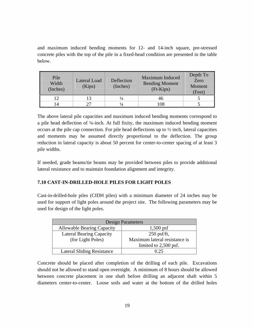
19
and maximum induced bending moments for 12- and 14-inch square, pre-stressed concrete piles with the top of the pile in a fixed-head condition are presented in the table below.
Pile Width
(Inches)
Lateral Load (Kips)
Deflection (Inches)
Maximum Induced Bending Moment
(Ft-Kips)
Depth To Zero
Moment (Feet)
12 13 ¼ 46 5 14 27 ¼ 108 5
The above lateral pile capacities and maximum induced bending moments correspond to a pile head deflection of ¼-inch. At full fixity, the maximum induced bending moment occurs at the pile cap connection. For pile head deflections up to ½ inch, lateral capacities and moments may be assumed directly proportional to the deflection. The group reduction in lateral capacity is about 50 percent for center-to-center spacing of at least 3 pile widths. If needed, grade beams/tie beams may be provided between piles to provide additional lateral resistance and to maintain foundation alignment and integrity. 7.10 CAST-IN-DRILLED-HOLE PILES FOR LIGHT POLES Cast-in-drilled-hole piles (CIDH piles) with a minimum diameter of 24 inches may be used for support of light poles around the project site. The following parameters may be used for design of the light poles.
Design Parameters Allowable Bearing Capacity 1,500 psf
Lateral Bearing Capacity (for Light Poles)
250 psf/ft, Maximum lateral resistance is
limited to 2,500 psf. Lateral Sliding Resistance 0.25
Concrete should be placed after completion of the drilling of each pile. Excavations should not be allowed to stand open overnight. A minimum of 8 hours should be allowed between concrete placement in one shaft before drilling an adjacent shaft within 5 diameters center-to-center. Loose soils and water at the bottom of the drilled holes

20
should be removed to the extent possible. All drilled pile construction should be performed in accordance with the latest edition of ACI 336.1, "Standard Specifications for Construction of Drilled Piles”. 7.11 PAVEMENTS AND SIDEWALKS To provide uniform and adequate support, general surfaces to be paved with either Portland cement concrete or asphaltic concrete should be underlain by at least 24 inches of granular fill compacted to 95 percent relative density. In areas to be provided with settlement-sensitive coverings such as decorative tile or stone, we recommend providing a minimum 5 feet of engineered fill under the pavement. The actual thickness of the engineered fill will vary depending on the thickness of existing uncertified fills to be removed. A moisture barrier is recommended under all floor slabs to be overlain by moisture-sensitive floor covering. A plastic or vinyl membrane may be used for this purpose and should be placed between two layers of moist sand, each at least 2 inches thick, to promote uniform curing of the concrete and to protect the membrane during construction. For design of slabs and rigid pavements and for estimating their deflections, a modulus of subgrade reaction (k) of 250 pounds per square inch per inch deflection (pci) may be used. 7.12 PAVEMENT STRUCTURAL SECTIONS Pavement subgrades at the project site are anticipated to expose loose surficial soils. Because of the unpredictability of traffic use, we have recommended pavement structural sections based on our experience with similar projects and subsurface materials. The intention is to keep the initial costs minimal, while additional asphalt concrete surfacing may be added later, if needed. R-value testing may be necessary during construction for verification purposes so as to consider any need for modifications. Recommended minimum thickness of flexible pavements for Traffic Index (TI) values of 4.0, 5.0 and 7.0 are provided below:

21
Pavement Thickness (Inches) Pavement Description Traffic Index (TI) Asphaltic Concrete Aggregate Base
Truck Drive Areas 7 4 10 Car Drive Areas 5 to 5½ 4 7 Parking Areas 4 3 6
To provide uniform support, all pavement areas should be provided with at least 24 inches of engineered fill compacted to 95 percent of the maximum dry density per ASTM D-1557. We recommend that the areas to receive pavements be prepared in accordance with the applicable preceding recommendations. Adequate grade or drainage should be provided to prevent ponding of water on the pavement. Alternatively, all areas subject to future truck traffic (fire trucks, trucks with 5 axles or greater) may be overlain by a minimum of 7½ inches of reinforced concrete over 6 inches aggregate base. All concrete pavements should be provided with nominal reinforcement. Pavements may be reinforced using minimum No. 3 bars at 12-inch on-center, each way. Aggregate base should satisfy Caltrans Class 2 gradation requirements and should have a minimum R-value of 78. All gradation and R-value should be confirmed by the geotechnical engineer during construction. All base materials should be compacted to a minimum of 95 percent of the maximum dry density per ASTM D-1557. 7.13 SEISMIC PARAMETERS 7.13.1 Probabilistic Seismic Hazard Assessment A probabilistic seismic hazard analysis (PSHA) was performed using the computer program FRISKSP (Blake, 2000) to estimate the Peak Horizontal Ground Accelerations (PHGA) that could occur at the site. The site latitude and longitude inputs were 36.6512 degrees 120.5845 degrees, respectively. Various probabilistic density functions were used in the analysis to assess the uncertainty inherent in the calculations with respect to magnitude, distance, and ground motion. An average of three attenuation relationships (Abrahamson and Silva, 1977, Boore et al., 1997, and Sadigh et al, 1997) were used to estimate ground motions for the site underlain by deep alluvial deposits.

22
The results of the analysis suggest that the estimated PHGA with a 10 percent probability of exceedance in 50 years is approximately 0.48g (recurrence interval of 475 years). This level of ground motion is considered the Design Basis Earthquake (DBE). 7.13.2 California Building Code (2001 CBC) For determination of the site coefficient, a subsurface soil profile corresponding to a site profile type SD, in accordance with Table No. 16-J of the 2001 California Building Code may be used. The project site may be assumed to be located within Seismic Zone 4. According to the Maps of Known Active Fault Source Zone, prepared by the California Department of Conservation Division of Mines and Geology (1998), the proposed Project site is located greater than 10 kilometers from the Ortigalita Fault Zone. A seismic source Type B should be used for the site when selecting a near source factor from Tables 16-S and 16-T of the 2001 CBC. In summary, based on URS’ review of the available geotechnical and geological data, the seismic parameters for the site, according to 2001 CBC, are presented in the table below.
Seismic Design Parameters Assumed Site Profile Type SD
Fault Type B Distance to Fault > 10 km
Seismic Zone Factor (Z) 0.40 Seismic Coefficient (Ca) 0.44 Seismic Coefficient (Cv) 0.64 Near-Source Factor (Na) 1.0 Near-Source Factor (Nv) 1.0
7.14 SURFACE DRAINAGE The ground surface of the site should be adequately sloped to direct water away from the foundations. Areas where water could pond should be eliminated by the use of area drains. Area drains should not be placed next to or in contact with the foundations. The ground surface should be adequately sloped away from structures toward the area drains.
8.0 DESIGN REVIEW We recommend that the geotechnical aspects of the project be reviewed by the geotechnical engineer during the design process. The scope of services may include

23
assistance to the design team in providing specific recommendations for special cases, reviewing the foundation design and evaluating the overall applicability of the recommendations presented in this report, reviewing the geotechnical portions of the project for possible cost savings through alternative approaches and reviewing the proposed construction techniques to evaluate if they satisfy the intent of the recommendations presented in this report.
9.0 CONSTRUCTION MONITORING As required under Section 3317 of the 2001 CBC, all earthwork and foundation construction should be monitored by a qualified engineer/technician under the supervision of the geotechnical engineer-of-record. Such monitoring should include, but not be limited to, the following:
• Site preparation -- site stripping, overexcavation, and recompaction; • Foundation excavation subgrades (prior to placing steel and concrete); • Placement of structural fills and backfills; and • All stone column or pile installations.
We recommend that URS be present to observe the soil conditions encountered during construction, to evaluate the applicability of the recommendations presented in this report to the soil conditions encountered, and to recommend appropriate changes in design or construction if conditions differ from those described herein.
10.0 LIMITATIONS URS warrants that our services are performed within the limits prescribed by our clients, with the usual thoroughness and competence of the engineering profession. No other warranty or representation, express or implied, is included or intended in this report.
- o0o -

24
The following are attached and complete this report:
Figure 1 Vicinity Map Figure 2 Plot Plan
Appendix A Exploration Borings Appendix B Geotechnical Laboratory Testing It has been a pleasure to assist you with this project. We look forward to being of further assistance as the project develops. Should you have any questions, please contact us. Respectfully submitted, URS CORPORATION S. Nesarajah, Ph.D., P.E., G.E. Arnel Bicol, P.E., G.E. Senior Project Engineer Principal Engineer
25
11.0 REFERENCES Bartow, J.A. 1988. Preliminary Geologic Map of the Monocline Ridge Quadrangle,
California. U.S. Geological Survey Open-File Report 88-528. Bartow, J.A., 1996. Geologic map of the West Border of the San Joaquin Valley in the
Panoche Creek-Cantua Creek Area, Fresno and San Benito Counties, California. U.S. Geological Suvery Miscellaneous Investigations Series Map I-2430.
Bartow, J.A., and W.R. Lettis. 1996. Preliminary Geologic Map of the Chounet Ranch
Quadrangle, California. Beard. S. and J. Laudon. 1988. Data for Ground-Water Test Holes in Fresno County,
Western San Joaquin Valley, California, June to August 1985. U.S. Geological Survey Open File Report 88-78.
Belitz, K. 1988. Character and Evolution of the Ground-Water Flow System in the
Central Part of the Western San Joaquin Valley, California. U.S. Geological Survey Open-File Report 87-573.
Belitz, K. and Heimes, F.J. 1990. Character and Evolution of the Ground-Water Flow
System in the Central Part of the Western San Joaquin Valley, California. U.S. Geological Survey Water-Supply Paper 2348.
Blake, T. F. (2000), FRISKSP, A computer program for the Probabilistic Estimation of
Peak Acceleration and Uniform Hazard Spectra Using 3-D Faults as earthquake Sources, Thomas F. Blake, Computer Services & Software.
Bull, W.B. 1964a. Geomorphology of Segmented Alluvial Fans in Western Fresno
County, California. U.S. Geological Survey Professional Paper 352-E. Bull, W.B. 1964b. Alluvial Fans and Near-Surface Subsidence in Western Fresno
County, California. U.S. Geological Survey Professional Paper 437-A. Bull, W.B. 1972. Prehistoric Near-Surface Subsidence Cracks in Western Fresno County,
California. U.S. Geological Survey Professional Paper 437-C.

26
Bull, W.B., and R.E. Miller. 1975. Land Subsidence Due to Ground-Water Withdrawal in the Los Banos-Kettleman City Area, California, Part 1. Changes in the Hydrologic Environment Conducive to Subsidence. U.S. Geological Survey Professional Paper 437-E.
Bull, W.B. 1975. Land Subsidence Due to Ground-Water Withdrawal in the Los Banos-
Kettleman City Area, California, Part 2. Subsidence and Compaction of Deposits. U.S. Geological Survey Professional Paper 437-F.
Bull, W.B., and J.F. Poland. 1975. Land Subsidence Due to Ground-Water Withdrawl in
the Los Banos-Kettleman City Area, California, Part 3. Interrelations of Water-Level Change, Change in Aquifer-System Thickness, and Subsidence. U.S. Geological Survey Professional Paper 437-G.
California Department of Conservation, Division of Mines and Geology. 1959a. Geologic
Map of California, San Luis Obispo Sheet. California Department of Conservation, Division of Mines and Geology. 1959b.
Geologic Map of California, Santa Cruz Sheet. California Department of Conservation, Division of Mines and Geology. 1978.
Limestone, Dolomite, and Shell Resources of the Coast Range Province, California. Bulletin 197.
California Department of Conservation, Division of Oil and Gas. 1985. California Oil
and Gas Fields, Central California. Publication TR 11. California Department of Conservation, Division of Oil and Gas. 2006. Oil and Gas
Maps: District 5. www.consrv.gov/dog/maps/d5_index_map1.htm. California Department of Conservation, Division of Mines and Geology. 1988. Mineral
Land Classification: Aggregate Materials in the Fresno Production-Consumption Region. Special Report 158.
California Department of Conservation, Division of Mines and Geology. 1999. Update of
Mineral Land Classification: Aggregate Materials in the Fresno Production-Consumption Region. Open-File Report 99-02.

27
California Department of Conservation, Division of Mines and Geology. 2000. Digital Images of Official Maps of Alquist-Priolo Earthquake Fault Zones of California, Central Coastal Region. DMG CD 2000-004.
California Department of Conservation, Division of Oil, Gas and Geothermal Resources.
1985. California Oil and Gas Fields. Publication TR-11. Croft, M.G. 1972. Subsurface Geology of the Late Tertiary and Quaternary Water-
Bearing Deposits of the Southern Part of the San Joaquin Valley, California. U.S. Geological Survey Water-Supply Paper 1999-H.
Davis, G.H. and J.F. Poland. 1957. Ground-Water Conditions in the Mendota – Huron
Area, Fresno and Kings Counties, California. U.S. Geological Survey Water-Supply Paper 1360-G.
Davis, G.H., J.H. Green, F.H. Olmsted, and D.W. Brown. 1959. Ground-Water
Conditions and Storage Capacity in the San Joaquin Valley, California. U.S. Geological Survey Water-Supply Paper 1469.
Davis, G.H., B.E. Lofgren, and S. Mack. 1964. Use of Ground-Water Reservoirs for
Storage of Surface Water in the San Joaquin Valley, California. U.S. Geological Survey Water-Supply Paper 1618.
Deverel, S.J., R.J. Gilliam, R. Fujii, J.A. Izbicki, and J.C. Fields. 1984. Areal Distribution
of Selenium and other Inorganic Constituents in Shallow Ground Water of the San Luis Drain Service Area, San Joaquin Valley, California: A Preliminary Study. U.S. Geological Survey Water-Resource Investigations Report 84-4319.
Diamond, J., and A.K. Williamson. 1983. A Summary of Ground-Water Pumpage in the
Central Valley, California, 1961-77. U.S. Geological Survey Water-Resources Investigations Report 83-4037.
Fresno County. 2000. Fresno County General Plan, Revised Public Review Draft,
Background Report. January.

28
Geomatrix Consultants. 1989. Geology and Hydrogeology of Selected Areas of the Panoche Fan, Western San Joaquin Valley, California. Consultants Report for Westlands Water District. January.
Gilliom, R.J., and others. 1989. Preliminary Assessment of Sources, Distribution, and
Mobility of Selenium in the San Joaquin Valley, California. U.S. Geological Survey Water Resources Investigation 88-4186.
Hotchkiss, W.R. 1972. Generalized Subsurface Geology of the Water-Bearing Deposits,
Northern San Joaquin Valley, California. U.S. Geological Survey Open-File Report 73-119.
International Conference of Building Officials. 1997. Uniform building Code, 1997. Vol.
2. Whittier, California. Ireland, R.L., J.F. Poland, and F.S. Riley. 1984. Land Subsidence in the San Joaquin
Valley, California as of 1980. U.S. Geological Survey Professional Paper 437-I. Ireland, R.L. 1986. Land Subsidence in the San Joaquin Valley, California as of 1983.
U.S. Geological Survey Water-Resources Investigations Report 85-4196. Johnson, A.I., R.P. Moston, and D.A. Morris. 1968. Physical and Hydrologic Properties
of Water-Bearing Deposits in Subsiding Areas in Central California. U.S. Geological Survey Professional Paper 497-A.
Jones and Stokes Associates. 1995. Conveyance of Nonproject Groundwater from
Canalside Project Using the California Aqueduct. Consultants Report for Westlands Water District. October.
Lade, P.V. and Lee, K.L. (1976), “Engineering Properties of Soils,” UCLA School of
Engineering Publication 7652 Lettis, W.R. 1982. Late Cenozoic Stratigraphy and Structure of the Western Margin of
the Central San Joaquin Valley, California. U.S. Geological Survey. 1971. Lia, S.S. and Whitman, R.V. (1986), “Overburden Correction Factors For Sand” JGED,
vol 112, No. 3, March, p.p. 373-377.

29
Mendenhall, W.C. 1908. Ground Waters of San Joaquin Valley, California. U.S. Geological Survey Water-Supply Paper 222.
Mendenhall, W.C., R.B. Dole, and H. Stabler. 1916. Groundwater in San Joaquin Valley,
California. U.S. Geological Survey Water-Supply Paper 398. Miller, R.E., J.H. Green, and G.H. Davis. 1971. Geology of the Compacting Deposits in
the Los Banos – Kettleman City Subsidence Area, California. U.S. Geological Survey Professional Paper 497-E.
Naval Facilities Engineering Command (1986), Soil Mechanics, Design Manual 7.01,
September, 1986. Naval Facilities Engineering Command (1986), Foundations & Earth Structures, Design
Manual 7.02, September 1986. Page, R.W. 1986. Geology of the Fresh Ground-Water Basin of the Central Valley,
California, with Texture Maps and Sections. U.S. Geological Survey Professional Paper 1401-C.
Peck, Ralph B.; Hanson, Walter, E.; Thornburn, Thomas H. (1974), Foundation
Engineering, 2nd Edition, John Wiley & Sons. Poland, J.F., B.E. Lofgren, F.S. Riley. 1972. Glossary of Selected Terms Useful in
Studies of the Mechanics of Aquifer Systems and Land Subsidence due to Fluid Withdrwal. U.S. Geological Survey Water-Supply Paper 2025.
Poland, J.F., B.E. Lofgren, R.L. Ireland, and R.G. Pugh. 1975. Land Subsidence in the
San Joaquin Valley, California, as of 1972. U.S. Geological Survey Professional Paper 437-H.
Rymer, M.J., and W.L. Ellsworth, editors. 1990. The Coalinga, California, Earthquake of
May 2, 1983. U.S. Geological Survey Professional Paper 1487. U.S. Army Corps of Engineers (1993), “Design of Pile Foundation.” U.S. Geological Survey. 1971a. Chaney Ranch. 1:24,000-Scale Topographic Map.

30
U.S. Geological Survey. 1971b. Chounet Ranch. 1:24,000-Scale Topographic Map. U.S. Geological Survey. 1971c. Monocline Ridge. 1:24,000-Scale Topographic Map. U.S. Geological Survey. 1971d. Tumey Hills. 1:24,000-Scale Topographic Map. U.S. Geological Survey. 1987. Water Well Drillers Report, State Well Number 15S/13E-5F2. July. U.S. Geological Survey. 2004. U.S. Geological Survey Minerals Yearbook – 2004. U.S. Geolgogical Survey. 2006a. USGS Earthquake Hazards Program – Northern California, Great Valley Thrust Faults. quake.wr.usgs.gov/prepare/ncep/greatvalley.html. U.S. Geological Survey. 2006b. Quaternary Fault and Fold Database of the United States. earthquake.usgs.gov/regional/qfaults/. Westlands Water District. 2006. Deep Groundwater Conditions Report. March. Report
available at www.westlandswater.org under Water & Power, Groundwater and Maps. Williamson, A.K., D.E. Prudic, and L.A. Swain. 1989. Ground-Water Flow in the Central
Valley, California. U.S. Geological Survey Professional Paper 1401-D. 2001 Uniform Building Code, Volume 2.


B - 1
LABORATORY TESTING B.1 GENERAL Laboratory tests were performed on selected representative samples as an aid in classifying the soils and to evaluate the physical properties of the soils affecting foundation design and construction procedures. Tests performed are indicated on the Logs of Borings. A description of the laboratory testing program is presented below. B.2 MOISTURE AND DENSITY TESTS Moisture content and density tests were performed on a number of samples recovered from the borings. The results of these tests were used to compute existing soil overburden pressures, to correlate strength and compressibility data from tested samples with those not tested, and to aid in evaluating soil properties. The tests were performed in accordance with ASTM Test Methods D-2937 and D-2216, respectively. The results of these tests are shown on the Logs of Borings. B.3 ATTERBERG LIMTS Atterberg Limits tests were performed to aid in classification and to evaluate the plasticity characteristics of fine-grained materials encountered at the site. These tests were performed in accordance with ASTM Test Method D-4318. The results of these tests are summarized on the Logs of Borings and summarized in Figure B-1.
B.4 SIEVE ANALYSIS Percent passing No. 200 sieve and full grain size sieve (2 inch to No. 200 sieve) tests were performed on selected samples of soils encountered at the site. These tests were performed to evaluate the gradation characteristics of the soils and to aid in their classification. The tests were performed in accordance with ASTM Test Methods D-1140 and D-698, respectively. The results are shown on the Logs of Borings.
B - 2
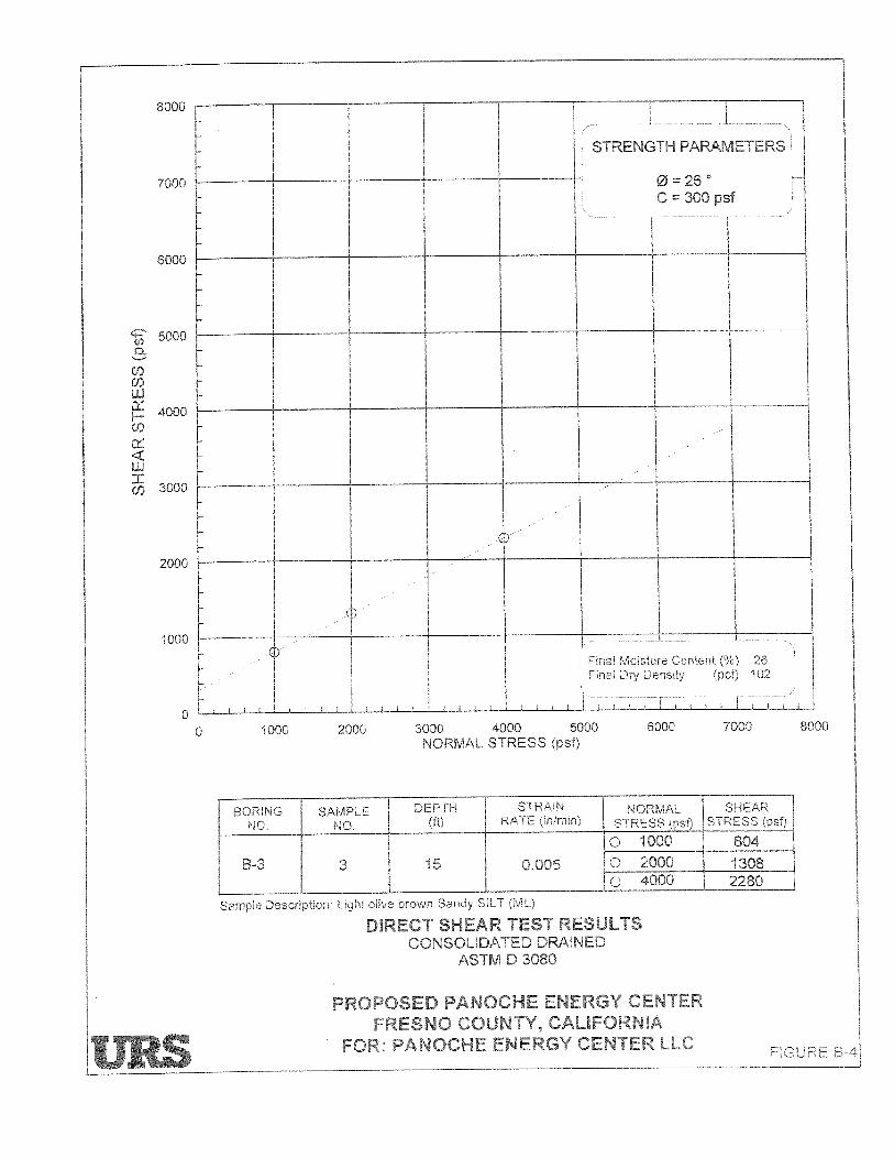
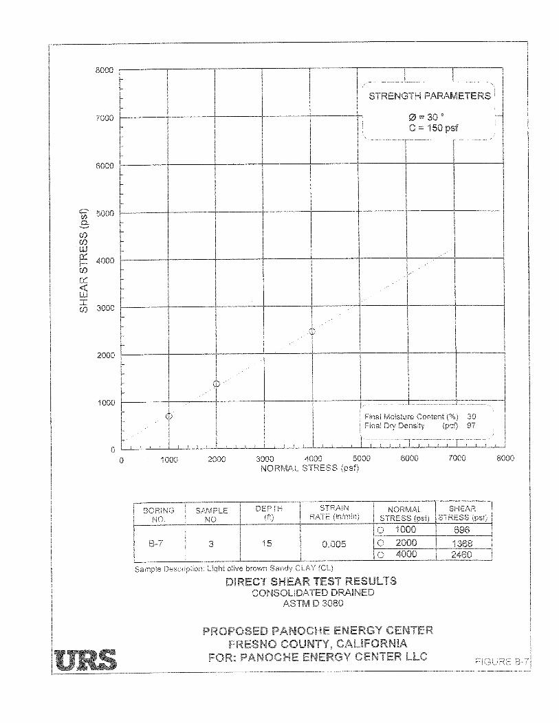
B.5 DIRECT SHEAR TESTS Consolidated-drained (saturated) direct shear tests were performed on selected undisturbed samples to evaluate shear strength parameters of the site soils. The direct shear tests were performed in accordance with ASTM Test Method D-3080. The results of these tests are presented in Figures B-2 through B-17. B.6 PERMEABILITY TESTS
Permeability tests (hydraulic conductivity) were performed to determine the permeability of representative soils within the upper strata of the site. These tests were performed in accordance with ASTM Test Method D-5084. The test results are presented on Figures B-18 through B-20.
B.7 CONSOLIDATION
One-dimensional consolidation tests were performed on representative samples of the fine-grained soils to evaluate the compressibility characteristics of the site soils. These tests were preformed in accordance with ASTM Test Method D-2435. The consolidation test results are presented on Figures B-21 through B-28.
B.8 COMPACTION
Compaction tests were performed on representative bulk samples of the onsite surficial soils to evaluate the maximum dry density and optimum moisture content of the soils. The tests were performed in accordance with ASTM Test Method D-1557. Results of the compaction tests are presented in Figures B-29 through B-31.