geotechnical report - gsp group | planning | urban design
TRANSCRIPT

PROJECT NO.: SM 177596-G August 22, 2017 ST. JEAN REALITY INC. BROKERAGE 88 Wilson Street West – 2nd Floor Ancaster, Ontario L9G 1N2 Attention: Robin St. Jean President/Sales Representative
GEOTECHNICAL INVESTIGATION PROPOSED CONDOMINIUM BUILDING
282 MACNAB STREET NORTH HAMILTON, ONTARIO
Dear Mr. St. Jean, Further to your authorisation, SOIL-MAT ENGINEERS & CONSULTANTS LTD. has completed the fieldwork, laboratory testing, and report preparation in connection with the above noted project. The fieldwork was completed in general accordance with our proposal, P6845, dated May 30, 2017, revised June 16, 2017. Our comments and recommendations, based on our findings at the three borehole locations are presented herein. 1. INTRODUCTION We understand that the project will involve the construction of a 13-storey condominium building with up to two underground parking levels at the property currently located at 282 MacNab Street North in Hamilton, Ontario. Our office was provided with previous Phase I and II ESA reports for the site prepared by MTE Consultants Inc. for review in preparing the geotechnical fieldwork and report. These reports have been used to supplement our fieldwork in preparation of this report. The purpose of this geotechnical investigation work was to assess the subsurface soil and groundwater conditions, and to provide our comments and recommendations with respect to the design and construction of the proposed development, from a geotechnical point of view. This report is based on the above summarized project description, and on the assumption that the design and construction will be performed in accordance with applicable codes and standards. Any significant deviations from the proposed project
Geotechnical Engineering •••• Environmental Assessments •••• Soils •••• Concrete •••• Asphalt
SOIL-MAT ENGINEERS & CONSULTANTS LTD. www.soil-mat.ca [email protected] TF: 800.243.1922
Hamilton: 130 Lancing Drive L8W 3A1 T: 905.318.7440 F: 905.318.7455
Milton: PO Box 40012 Derry Heights PO L9T 7W4 T: 800.243.1922

PROJECT NO.: SM 177596-G
GEOTECHNICAL INVESTIGATION
PROPOSED CONDOMINIUM BUILDING
282 MACNAB STREET NORTH
HAMILTON, ONTARIO
2
design may void the recommendations given in this report. If significant changes are made to the proposed design, this office must be consulted to review the new design with respect to the results of this investigation. It is noted that the environmental aspects of the site have not been addressed in the scope of this investigation. 2. PROCEDURE A total of three [3] sampled boreholes were advanced at the locations illustrated in the attached Drawing No. 1, Borehole Location Plan. The borings were advanced using hollow stem continuous flight augers and mud rotary drilling equipment between July 13 and 24, 2017 under the direction and supervision of a staff member of SOIL-MAT
ENGINEERS & CONSULTANTS LTD., to depths of between approximately 15.9 and 25.1 metres below the existing ground surface. Representative samples of the subsoils were recovered from the borings at selected depth intervals using split barrel sampling equipment driven in accordance with the requirements of the ASTM test specification D1586, Standard Penetration Resistance Testing. After undergoing a general field examination, the soil samples were preserved and transported to the SOIL-MAT laboratory for visual, tactile, and olfactory classifications. Routine moisture content tests were performed on all soil samples recovered from the borings. Selected cohesive samples were subjected to hand penetrometer testing. The boreholes were located in the field by a representative of SOIL-MAT ENGINEERS. The ground surface elevations of borings were referenced to a site specific geodetic benchmark described as the top of the catch basin on the west side of the existing building. This benchmark was noted to have an elevation of 88.67 metres, as indicated on the Mackay Mackey & Peters Limited survey of the site, provided to our office. Details of the conditions encountered in the boreholes, together with the results of field and laboratory tests, are presented in Borehole Log Nos. 1 to 3, inclusive, following the text of this report. It is noted that the boundaries of soil types indicated on the borehole logs are inferred from non-continuous soil sampling and observations made during drilling. These boundaries are intended to reflect transition zones for the purpose of geotechnical design and therefore should not be construed as the exact planes of geological change.

PROJECT NO.: SM 177596-G
GEOTECHNICAL INVESTIGATION
PROPOSED CONDOMINIUM BUILDING
282 MACNAB STREET NORTH
HAMILTON, ONTARIO
3
3. SITE DESCRIPTION AND SUBSURFACE CONDITIONS The subject site encompasses the property located at 282 MacNab Street North in Hamilton, Ontario. The site is bounded to the south by a church and existing residential properties, to the west by MacNab Street North, and to the east and north by the existing West Harbour GO Station. The majority of the site is occupied by a 2-storey metal clad industrial building and a 2-storey vinyl sided building, as well as a few smaller storage structures. The remainder of the site is asphalt or concrete paved, and is generally flat and even, level with MacNab Street North. The subsurface conditions encountered at the borehole locations are summarized as follows: Pavement Structure All of the boreholes were advanced through existing concrete slabs, which were noted to be approximately 150 millimetres in thickness. It is noted that the depth of the concrete may vary across the site, and from the depths encountered at the borehole locations. Silty Sand Native reddish brown silty sand was encountered beneath the concrete slabs at all borehole locations. The silty sand encountered was fine in gradation, with occasional clayey inclusions, and in a generally loose to compact state. The upper levels of the sand encountered generally had a ‘reworked’ appearance, and may be fill materials associated with the construction of the existing structures. Silty sand was proven to depths of approximately 7.2, 10.2, and 10.2 metres in Borehole Nos. 1, 2, and 3, respectively. Silty Clay/Clayey Silt Native silty clay/clayey silt was encountered beneath the silty sand at the Borehole Locations. This native cohesive soil was grey in colour, contained traces of sand and fine gravel, and was generally stiff to soft in consistency. Hand penetrometer testing yielded readings on the order of approximately 0.25 to 2.5 kg/cm2 [~tsf]. A number of field shear vane tests were conducted within the silty clay/clayey silt deposit. These results indicate the silty clay to be a normally consolidated cohesive deposit, with moderate shear strength and low sensitivity. The results are summarised in the following table.

PROJECT NO.: SM 177596-G
GEOTECHNICAL INVESTIGATION
PROPOSED CONDOMINIUM BUILDING
282 MACNAB STREET NORTH
HAMILTON, ONTARIO
4
Summary of Field Shear Vane Testing
BH No. Depth [m] Shear Strength [kPa] Sensitivity
Ultimate, SU Remold, SR
1 13.4 97 53 1.8
1 16.5 88.5 53 1.7
1 19.5 97 53 1.8
2 15.0 71 44 1.6
2 16.5 62 53 1.2
3 16.5 53 35 1.5
3 19.5 71 53 1.3
3 22.5 125 97 1.3
Queenston Shale Bedrock Queenston Shale bedrock was encountered beneath the silty clay/clayey silt in Borehole Nos. 1 and 3 at depths of approximately 24.6 and 24.4 metres, respectively. The Queenston shale bedrock was red in colour with occasional more resistant grey layers, weathered in the upper levels, becoming more sound with depth. The Queenston Shale bedrock was not cored as part of this investigation. From past experience and available published information the upper weathered levels of Queenston Shale is generally weak in terms of rock, with typical unconfined compressive strengths on the order of perhaps 30 to 80 MPa in the more sound levels of bedrock below the upper weathered levels. Groundwater Observations Borehole No. 2 was recorded as ‘wet’ at a depth of approximately 4.1 metres below the existing surface, while the remaining boreholes were recorded as ‘dry’ upon completion of drilling. It is noted that insufficient time would have passed for the static groundwater level to stabilise in the open boreholes. However, in fine grained and cohesive soils, the static groundwater level generally coincides with the transition in colour from brown to grey. In addition, water level readings were taken on July 28, 2017 from existing monitoring wells installed as part of the Phase Two ESA referenced above. These readings have been summarised as follows:
Monitoring Well No. MW102-16 MW104-16 MW105-16
Groundwater Depth (m) 4.60 4.67 4.40

PROJECT NO.: SM 177596-G
GEOTECHNICAL INVESTIGATION
PROPOSED CONDOMINIUM BUILDING
282 MACNAB STREET NORTH
HAMILTON, ONTARIO
5
Based on these readings, as well as our observations during drill, the static groundwater level is estimated at a depth of approximately 4 to 5 metres below the existing ground surface. This groundwater level would be anticipated to fluctuate with season, notably higher during the ‘wet’ seasons. 4. FOUNDATION CONSIDERATIONS The subsoil conditions encountered in the boreholes are such that both shallow and deep foundation options may be considered suitable to support the proposed structure. Depending on the proposed loads, it may be possible to support the proposed structure on conventional spread footings or a raft slab founded on the native soils. However, it is likely that the loads associated with the proposed 13-storey high rise structure will be such that shallow foundations are not feasible. In such case an intermediate foundation scheme such as ground improvement to support a raft slab may be considered, or a deep foundation scheme extending to bedrock will be required. 4.1 SHALLOW FOUNDATIONS 4.1.1 SPREAD FOOTINGS With two underground parking levels, it is anticipated that the proposed founding level will be approximately 6 to 8 metres below the existing ground surface. Shallow foundations bearing on the native silty sand at these depths may be considered, as described above. Spread footings founded on the native compact silty sand may be designed on the basis of 150 kPa [~3,000 psf] SLS and 225 kPa [~4,500 psf] ULS. The native silty sand will be prone to disturbance from groundwater, foot and construction traffic, therefore it is recommended that the founding soils be protected with a thin lean-mix concrete product [~5 MPa] ‘mud slab’ placed as soon as possible after excavation and evaluation. 4.1.2 RAFT SLAB Where the required structural loads results in a building footprint coverage by the spread footings of greater than 50 percent, consideration should be given to supporting structure on a raft slab foundation. The raft slab may be designed considering design bearing values of 100 kPa [~2,000 psf] ULS and 150 kPa [~3,000 psf] ULS. Alternatively, if a flexible design approach is used, a value of subgrade modulus of k = 30 MN/m3 [110 pci] may be considered. In addition, a raft slab may also be designed to resign hydrostatic uplift pressures associated with the static groundwater level being above the founding depth.

PROJECT NO.: SM 177596-G
GEOTECHNICAL INVESTIGATION
PROPOSED CONDOMINIUM BUILDING
282 MACNAB STREET NORTH
HAMILTON, ONTARIO
6
4.1.3 GROUND IMPROVEMENT It is anticipated that the foundation loads for the proposed structure would require a higher bearing capacity than those values noted above. It may be possible to increase the available design bearing pressure in the existing subsurface soils to support the proposed condominium building on conventional spread footings or a raft slab via Ground Improvement. This option could consist of the installation of Rammed Aggregate Piers [RAP] or displacement piers to densify the subsurface soils. This method uses a ram of proprietary design to compact aggregate into the subsurface soils, which would increase the available bearing capacity and may allow for the use of spread footings or a raft slab. As these systems are proprietary in nature it is recommended to consult with the specialty design-build contractors regarding the feasibility and cost estimate for such foundation systems. 4.2 DEEP FOUNDATIONS 4.2.1 CAISSONS Given the anticipated relatively high loads of the proposed 13-storey structure, the use of deep foundation schemes extending to the underlying Queenston shale bedrock, such as caissons or driven piles, is likely preferred from a structural point of view. Caissons can be readily installed through the overburden sand and clay soils into the underlying Queenston shale bedrock. The installation of caissons would produce relatively limited vibrations in the area of the site and so are likely preferred over driven piles. Caisson foundations should extend a minimum of one caisson diameter into the Queenston shale bedrock and may be conservatively designed using a factored Ultimate Limit State [ULS] bearing capacity of 1,500 kPa [~30,000 psf]. Since it will be necessary for the bedrock to fail in order to realise serviceability tolerances, the unfactored Serviceability Limit State [SLS] value may also be taken as 1,500 kPa [~30,000 psf]. Where caissons extend through the upper weathered Shale and into more sound bedrock [a minimum of 1.5 metres or more] it would be feasible to design caissons to also take advantage of skin friction within the rock. A unit skin friction resistance of ULS = SLS = 250 kPa [~5,000 psf] may be considered. Higher bearing and skin friction values may be available at greater depth within the less weathered Queenston Shale bedrock, however would need to be confirmed through additional investigation including bedrock coring. Uplift capacity could be readily achieved with the skin friction on deeper caissons.

PROJECT NO.: SM 177596-G
GEOTECHNICAL INVESTIGATION
PROPOSED CONDOMINIUM BUILDING
282 MACNAB STREET NORTH
HAMILTON, ONTARIO
7
All caissons must be installed using a steel liner to maintain the integrity of the open hole and prevent the infiltration of groundwater. The depth of silty clay/clayey silt overburden above the bedrock should allow for the liner to ‘seal’ and restrict the infiltration of groundwater to allow for dewatering by pumping from the base of the caissons. Where minor infiltration into the open caisson is experienced the contractor should be prepared with bags of dry cement powder to be dropped into the open caisson and ‘mixed’ with any minor water immediately prior to the placement of caisson concrete. In the event that it is not possible to fully dewater the open caissons, the contractor should be prepared to place concrete by means of a ‘tremmie’ pipe method. The contractor should maintain a positive head of concrete in the liner while it is being removed to avoid the instruction of loose materials [known as ‘necking’] into the caisson. The base of the caissons should be thoroughly cleaned to remove all loose or disturbed material immediately prior to the placement of concrete. A specialty contractor should be consulted with respect to the design and installation of caissons. The installation of caissons should be monitored by a representative of SOIL-MAT ENGINEERS &
CONSULTANTS LTD. 4.2.2 MICROPILES The proposed structure may also be supported using grouted micropiles. The micropiles, typically 125 to 300 millimetres in diameter, would be drilled and grouted into the Queenston shale bedrock, below the upper weathered levels, and have been used to support loads up to 2,500 kN [~250 tons] per pile. The micropiles are drilled with a steel casing to the bedrock, a steel bar is placed down the middle and grouted with high strength grout to transfer loads to the bedrock. For preliminary design purposes a grout to bedrock bond strength of 250 kPa [~5,000 psf] may be considered. Micropiles offer the advantage of relatively rapid installation, do not require the removal of large volumes of spoil, and are installed with negligible vibrations. As micropiles tend to the proprietary in nature, a specialty contractor should be consulted in the design process. 4.3 GENERAL FOUNDATION CONSIDERATIONS It is noted that the SLS value represents the Serviceability Limit State, which is governed by the tolerable deflection [settlement] based on the proposed building type, using unfactored load combinations. The ULS value represents the Ultimate Limit State and is intended to reflect an upper limit of the available bearing capacity of the founding soils in terms of geotechnical design, using factored load combinations. There is no direct relationship between ULS and SLS; rather they are a function of the soil type and the tolerable deflections for serviceability, respectively. As noted in the preceding text, the SLS and ULS bearing capacities are equivalent within the Queenston Shale Bedrock, as in order for deflections reaching serviceability limits to be realized, failure of the bedrock would need to occur.

PROJECT NO.: SM 177596-G
GEOTECHNICAL INVESTIGATION
PROPOSED CONDOMINIUM BUILDING
282 MACNAB STREET NORTH
HAMILTON, ONTARIO
8
All footings, caisson caps, grade beams, etc., exposed to the environment must be provided with a minimum of 1.2 metres of earth cover or equivalent insulation to protect against frost damage. This frost protection would also be required if construction were undertaken during the winter months. All footings and foundations should be designed and constructed in accordance with the current Ontario Building Code. As the static groundwater level is estimated above the anticipated founding level, the foundations should be constructed to be watertight, and designed to resist the hydrostatic pressured associated with an elevated groundwater level. In the event that a raft slab is utilised, this should be readily accommodated at the excavation base with the raft slab itself. It is noted that it may be possible to sufficiently control groundwater buildup around the foundations with an appropriately designed perimeter and underfloor drainage system, however additional studies including pump tests would be required to accurately estimate the rate of infiltration of groundwater. With foundations designed as outlined above and as required by the Building Code, and with careful attention paid to construction detail, total and differential settlements should be small, and certainly well within normally tolerated limits of 25 and 20 millimetres, respectively, for the type of building and occupancy expected. It is imperative that a soils engineer be retained from this office to provide geotechnical engineering services during the excavation and foundation construction phases of the project. This is to observe compliance with the design concepts and recommendations of this report and to allow changes to be made in the event that subsurface conditions differ from the conditions identified at the borehole locations. 5. LATERAL EARTH PRESSURE The lateral earth pressures on basement walls can be estimated on the basis of a retained soil unit weight, [wet], of 20 kN/m3 [~127 pcf]. The coefficient of lateral earth pressure may be taken as, Ko = 0.5 in fill against rigid walls [at rest condition]. Any additional pressures due to surcharge loading, such as adjacent structures, roadways, parked vehicles, floor slab loading, etc. must be included in the design.

PROJECT NO.: SM 177596-G
GEOTECHNICAL INVESTIGATION
PROPOSED CONDOMINIUM BUILDING
282 MACNAB STREET NORTH
HAMILTON, ONTARIO
9
6. SEISMIC DESIGN CONSIDERATIONS The structure shall be designed according to Section 4.1.8 of the Ontario Building Code, Ontario Regulation 332/12. Based on the subsurface soil conditions encountered in this investigation the applicable Site Classification for the seismic design is Site Class D – Stiff Soil, based on the average soil characteristics for the site. It is noted that a seismic Site Class of C may be available, however would need to be confirmed via site specific shear wave velocity testing. The seismic data, from Supplementary Standard SB-1 of the Ontario Building Code, for Hamilton, below the escarpment and east of the 403 are as follows.
Sa(0.2) Sa(0.5) Sa(1.0) Sa(2.0) PGA
0.320 0.170 0.064 0.022 0.180 7. EXCAVATIONS AND EXCAVATION SUPPORT CONSIDERATIONS 7.1 SERVICE EXCAVATIONS Shallow excavations for the installation of municipal service connections should be relatively straightforward. It is anticipated that such excavation would be readily advanced as open cuts through the native silty sand to depths of about 3.0 to 5.0 metres. The sides of excavations through the native silty sand and any surficial fill material would be expected to remain stable for the short construction period at slopes of 45 degrees. However, where wet seams are encountered, due to surface runoff, or during periods of extended precipitation, or where excavations extend near to below the static groundwater elevation, the sides of excavations should be expected to slump in as flat as 3 horizontal to 1 vertical, or flatter. Notwithstanding the above, all excavations must comply with the current Occupational Health and Safety Act and Regulations for Construction Projects. Excavation slopes steeper than those required in the Safety Act must be supported and a senior geotechnical engineer from this office should monitor the work. Support of the existing underground services and roadway adjacent to the project area must also be considered in assessing the excavation support requirements. 7.2 BUILDING EXCAVATIONS It is anticipated that excavations for the proposed underground basement levels will extend to depths of up to about 6 to 8 metres below the existing grade, into the native silty sand. As noted above, the static groundwater level is anticipated at a depth of approximately 4 to 5 metres below the existing ground surface, which will be within the

PROJECT NO.: SM 177596-G
GEOTECHNICAL INVESTIGATION
PROPOSED CONDOMINIUM BUILDING
282 MACNAB STREET NORTH
HAMILTON, ONTARIO
10
anticipated excavation depth. It is anticipated that the basement levels will extend to, or close to, the property line requiring near vertical excavations. As such the provision of excavation support measures will be required. As the excavations will be through silty sand below the static groundwater level, the use of caisson walls are anticipated to be required, to sufficiently prevent the infiltration of groundwater through the relatively permeable silty sand soils, and loss of ground beneath adjacent structures, roadways, etc. The shoring system should be designed to allow for the construction of the foundation walls using single face, or ‘blind side’ construction techniques. All excavations must comply with the current Occupational Health and Safety Act and Regulations for Construction Projects. A specialty contractor or shoring consultant should be consulted with respect to the design of the shoring system. For preliminary design purposes the shoring system should be designed on the basis of a retained soil unit weight of wet = 20.0 kN/m3 [~127 pcf] and submerged = 10.0 kN/m3 [~64 pcf], and a lateral earth pressure coefficient of Ko = 0.5 (at rest case) or KA = 0.33 (active case). The shoring system should be monitored during construction, and the contractor should have a contingency plan in place to be implemented should deflections of the shoring system exceed the tolerable limits. In addition, it is imperative that a pre-construction condition survey be conducted of the adjacent structures, roadways, etc. in order to document the existing conditions prior to the commencement of construction. This will allow for comparison and assessment in the event that disturbance due to construction activities is claimed. The shoring can be supported either by anchors extending into the overburden soil or by rakers extending into the excavation, although from a contractors point of view, tie-back anchors would be preferred, provided they can be installed to avoid adjacent foundations and underground utilities and permission can be obtained from adjacent property owners. It is noted that significant movements of the shoring system may take place if conventional rakers are used to support the shoring system since compression of the members and the supporting footings must occur before the rakers can begin to carry load. In this regard, anchors are preferred since they allow pre-stressing of the shoring system to the design load even before the excavations reach their final grade. Alternatively, the rakers can be designed to allow jacking in of the design load, and thus eliminating/minimising movements. Rakers should be supported on footings bearing in the native silty sand designed using bearing values limited to ULS = 150 kPa [~3,000 psf] and SLS = 100 kPa [~2,000 psf].

PROJECT NO.: SM 177596-G
GEOTECHNICAL INVESTIGATION
PROPOSED CONDOMINIUM BUILDING
282 MACNAB STREET NORTH
HAMILTON, ONTARIO
11
It is anticipated that the general excavation for the structure will extend into the native silty sand. As the excavation base is anticipated to be below the estimated static groundwater level, instability of the silty sand soils should be anticipated. As such, efforts to stabilise the excavation base and protect from further disturbance from construction traffic. It is recommended that the excavation base be provided with a layer of granular material, such as Ontario Provincial Standard Specification [OPSS] Granular ‘B’, Type II [crushed bedrock], perhaps 300 millimetres thick and compacted to 100 per cent of its standard Proctor maximum dry density [SPMDD] to provide a stable ‘clean’ working surface. Alternatively, as mentioned above, a ‘mud’ slab consisting of ‘lean mix’ [~5 MPa] concrete, perhaps 75 to 100 millimetres thick, may be provided. It is noted that care must be taken by the contractor when completing excavations to the final base elevation. Construction equipment should be restricted from traveling on the exposed excavation base to prevent causing disturbance to the intended founding soils. The final layer of excavation should be conducted from a minimum of 2.0 metres above the design excavation base, and the base stabilised as discussed above prior to any equipment travelling on the base. Upon completion of excavation to the design founding elevation, construction equipment traffic should be limited on the excavation base as much as possible. As noted above, it is recommended that a ‘lean mix’ concrete ‘mud slab’ be placed as soon as possible upon completion of excavation. 8. BACKFILL CONSIDERATIONS The excavated soils will consist of the silty sand soils as described above, as well as fill materials associated with the existing structures. It is expected that the majority of the excavated materials will be transported from the project site to accommodate the basement levels. The fill materials should be removed from the site and disposed of at an appropriate off-site location, based on the environmental characteristics of the soils and requirements of the receiving property. Where feasible, the native silty sand materials are considered suitable for use as engineered fill, trench backfill, etc., provided that it is free of organics or otherwise deleterious materials. Some moisture conditioning may be required depending on the weather conditions at the time of construction. It is anticipated that the basement foundation walls will be constructed using single face ‘blind side’ methods and as such will not require significant volumes of backfill. Where required, the use of free draining, well-graded granular material such as an OPSS Granular ‘B’, Type II [crushed bedrock], is recommended for backfill against foundation walls, within the building area, or to raise the interior grade to the design subgrade level. This material is more readily compacted in restricted access areas, and generally presents a more positive support condition for concrete floor slabs and exterior

PROJECT NO.: SM 177596-G
GEOTECHNICAL INVESTIGATION
PROPOSED CONDOMINIUM BUILDING
282 MACNAB STREET NORTH
HAMILTON, ONTARIO
12
pavement. Alternative granular materials may also be considered, however should be reviewed and approved by our office prior to use. Any imported fill required in service trenches or to raise the subgrade elevation should have its moisture content within 3 per cent of its optimum moisture content and meet the necessary environmental guidelines. We note that where backfill material is placed near or slightly above its optimum moisture content, the potential for long-term settlements due to the ingress of groundwater and collapse of the fill structure is reduced. It is therefore very important that the placement moisture content of the backfill soils be within 3 per cent of its standard Proctor optimum moisture content during placement and compaction to minimise long term subsidence [settlement] of the fill mass. The backfilling and compaction operations should be monitored by a representative of SOIL-MAT to confirm uniform compaction of the backfill material to project specification requirements. Close supervision is prudent in areas that are not readily accessible to compaction equipment, for instance near the end of compaction 'runs', and around the foundation walls. Any service trench backfill within roadways or paved areas or fill material within the building area should be compacted to 100 per cent standard Proctor maximum dry density. A method should be developed to assess compaction efficiency employing the on-site compaction equipment and backfill materials during construction. 9. BASEMENT FLOOR SLAB The lower level parking garage floor slab may be constructed using conventional slab-on-grade techniques on a prepared subgrade, as outlined above. The exposed subgrade should be evaluated in the presence of a representative of SOIL-MAT
ENGINEERS. Any ‘soft’ spots delineated by this or by other means, should be sub-excavated and replaced with quality granular material compacted to 100 perfect of its SPMDD. As noted above within the Excavation Considerations section, the subgrade should be provided with a layer of 300 millimetres of OPSS Granular ‘B’, Type II, compacted to 100 per cent of its SPMDD, or alternatively a concrete ‘mud slab’. As with all concrete floor slabs, there is a tendency for the floor slabs to crack. The slab thickness, concrete mix design, the amount of steel and/or fibre reinforcement and/or wire mesh placed into the concrete slab, if any, will therefore be a function of the owner’s tolerance for cracks in, and movements of, the slabs-on-grade, etc. The ‘saw cuts’ in the concrete floors, for crack control, should extend to a minimum depth of 1/3 of the thickness of the slab.

PROJECT NO.: SM 177596-G
GEOTECHNICAL INVESTIGATION
PROPOSED CONDOMINIUM BUILDING
282 MACNAB STREET NORTH
HAMILTON, ONTARIO
13
A moisture barrier will be required under the floor slabs such as the placement of at least 200 millimetres of well-compacted 20 millimetre clear crushed stone. At a minimum the moisture barrier material should contain no more than 10 per cent passing the No. 4 sieve. Where ‘non-damp’ floor slabs are required, as for instance under sheet vinyl floor coverings, etc., extra efforts will be required to damp proof the floor slab, as with the additional provisions of a heavy ‘poly’ sheet, damp proofing sprays/membranes, etc. Where heavy ‘poly’ sheeting is used care should be taken in its placement, or a sufficiently heavy thickness provided, to prevent damage (puncturing and/or tearing). Curing of the slab-on-grade must be carefully specified to ensure that slab curl is minimised. This is especially critical during the hot summer months of the year when the surface of the slab tends to dry out quickly while high moisture conditions in the moisture barrier or water trapped on top of any ‘poly’ sheet at the saw cut joints and cracks, and at the edges of the slabs, maintains the underside of the slab in a moist condition. It is also important that the concrete mix design provide a limiting water/cement ratio and total cement content, which will mitigate moisture related problems with low permeance floor coverings, such as debonding of vinyl and ceramic tile. It is equally important that excess free water not be added to the concrete during its placement as this could increase the potential for shrinkage cracking and curling of the slab. 10. PERIMETER AND UNDERFLOOR DRAINAGE As noted above, the provision of two basement levels will extend below the measured static groundwater level. As such it is recommended that the foundations and basement slab be designed as water tight, making use of suitable membrane systems beneath the slab and against the exterior of foundation walls. This will likely require the use of foundation wall systems intended for ‘blind side’ or ‘single face’ application. The system should also incorporate a water-stop component between the footing/grade beam/mat slab and foundation walls. This approach would avoid the requirement for permanent drainage and dewatering systems. The enclosed Drawing No. 2 shows a schematic of the typical requirements for water tight basement foundation construction. Alternatively, depending on the conditions experienced during construction, the shoring system utilised [i.e. caisson wall], or pending more detailed evaluation of the groundwater conditions, it may be feasible to adequately control groundwater infiltration against the foundations using permanent drainage systems. The foundation wall drainage and water proofing system will need to be installed against the excavation shoring, often referred to as ‘blind side’ waterproofing. A variety of products are available for this application, such as Delta-Drain or TremDrain systems. Any system

PROJECT NO.: SM 177596-G
GEOTECHNICAL INVESTIGATION
PROPOSED CONDOMINIUM BUILDING
282 MACNAB STREET NORTH
HAMILTON, ONTARIO
14
should include a drainage board layer and/or waterproofing membrane intended for a ‘blind side’ application. The system should also incorporate a water-stop component between the footing/grade beam/mat slab and foundation walls. The volume of groundwater control required during construction should be monitored and used to assist in sizing the permanent drainage requirements. As a minimum it is recommended that the perimeter weeping tile consist of a 150 mm diameter perforated pipe, surrounded with 200 mm of 20 mm clear stone, with the stone in turn encased by a heavy filter fabric. The suppliers of the filter fabric should be consulted as to the type best suited for this project. To address the potential for the build-up of groundwater beneath the basement floor slabs under-floor drains should also be provided. These could consist of 150 millimetre diameter perforated plastic pipe, with a geofabric sock, placed in the clear stone beneath the floor slabs on nominal 4 metre centres. It is noted that the perimeter and under-floor drain piping should be kept separate from one another to avoid the potential for the perimeter drainage system to ‘charge’ water into the under-floor drains. The drains may outlet into a common sump pit. This office should examine the installation of the perimeter drains. Even a small break in the filtering materials could result in loss of fines into the drains with attendant performance difficulties, including settlements of the ground surface. The exterior grade around the structure should be sloped away from the structure to prevent the ponding of water against the foundation walls. The enclosed Drawing No. 3 shows a schematic of the typical requirements for perimeter and under floor drains for basement level construction.


Drawing No. 1
Drawn: SO Checked: IS
Date: August 2017
Project No. SM 177596-G
SM 177596-G Borehole Location Plan
Borehole Location Plan
Geotechnical InvestigationProposed Condominium
Building282 Macnab Street North
Hamilton, Ontario
SOIL-MAT
ENGINEERS & CONSULTANTS LTD.
1. This drawing should be read in conjunction with Soil-Mat Engineers& Consultants Ltd. Report No. SM 177596-G.
2. Borehole locations are approximate.
NOTES
LEGEND
Borehole LocationBH#
TBMTemporary BenchmarkTop of the catch basin – Elevation of
88.67
BH3BH2
BH1
MW102-16
MW104-16
MW105-16
TBM
Monitoring Wells By MTE

Log of Borehole No.
Project No:
Project:
Location:
Client:
Project Manager:
Borehole Location:
UTM Coordinates - N:
E:
Drill Method:
Drill Date:
Hole Size:
Drilling Contractor:
Datum:
Field Logged by:
Checked by:
Sheet: 1 of 3
Depth
0 0ft m
1
1
2
2
3
3
4
4
5
5
6
6
7
7
8
8
9
9
10
11
12
13
14
15
16
17
18
19
20
21
22
23
24
25
26
27
28
29
30
31
32
33
Ele
vation (
m)
Sym
bol
Description
Well
Data
Type
Num
ber
Blo
w C
ounts
Blo
ws/3
00m
m
Recovery
PP
(kgf/
cm
2)
U.W
t.(k
N/m
3)
Moisture Content w%
10 20 30 40
Standard Penetration Test blows/300mm
20 40 60 80
SAMPLE
Soil-Mat Engineers & Consultants Ltd.130 Lancing Drive, Hamilton, ON L8W 3A1T: 905.318.7440 F: 905.318.7455 E: [email protected]
1
SM 177596-G
Proposed Condominium Building
282 MacNab Street North
St. Jean Realty Inc. Brokerage
Kyle Richardson, P.Eng.
See Drawing No.1
88.68
81.50
Ground Surface
ConcreteApproximately 150 millimetres of concrete.
Silty Sand/Sandy SiltRedish brown, occasional clay inclusions, loose to compact.
Silty Clay/Clayey SiltGrey, trace sand in upper levels, very stiff to soft.
SS
SS
SS
SS
SS
SS
SS
SS
1
2
3
4
5
6
7
8
2,3,2,4
3,2,5,6
2,4,5,7
5,7,4,4
5,3,7,4
5,7,9,8
3,4,9,10
7,9,11,15
5
7
9
11
10
16
13
20
4.5
4
4.5
Mud Rotary
July 13, 2017
200 millimetres
Davis
Geodetic
S. Onisoru
KR

Log of Borehole No.
Project No:
Project:
Location:
Client:
Project Manager:
Borehole Location:
UTM Coordinates - N:
E:
Drill Method:
Drill Date:
Hole Size:
Drilling Contractor:
Datum:
Field Logged by:
Checked by:
Sheet: 2 of 3
Depth
11
12
13
14
15
16
17
18
19
34
35
36
37
38
39
40
41
42
43
44
45
46
47
48
49
50
51
52
53
54
55
56
57
58
59
60
61
62
63
64
65
Ele
vation (
m)
Sym
bol
Description
Well
Data
Type
Num
ber
Blo
w C
ounts
Blo
ws/3
00m
m
Recovery
PP
(kgf/
cm
2)
U.W
t.(k
N/m
3)
Moisture Content w%
10 20 30 40
Standard Penetration Test blows/300mm
20 40 60 80
SAMPLE
Soil-Mat Engineers & Consultants Ltd.130 Lancing Drive, Hamilton, ON L8W 3A1T: 905.318.7440 F: 905.318.7455 E: [email protected]
1
SM 177596-G
Proposed Condominium Building
282 MacNab Street North
St. Jean Realty Inc. Brokerage
Kyle Richardson, P.Eng.
See Drawing No.1
SS
SS
SS
SS
9
10
11
12
2,1,2,2
0,0,2,2
0,1,1,2
1,1,2,2
3
2
2
3
Mud Rotary
July 13, 2017
200 millimetres
Davis
Geodetic
S. Onisoru
KR
Silty Clay/Clayey SiltGrey, trace sand in upper levels, very stiff to soft.
Shear Vane SU - 88.5 kPaSR - 53 kPa
Shear Vane SU - 97 kPaSR - 53 kPa
Shear VaneSU - 97 kPaSR - 53 kPa

Log of Borehole No.
Project No:
Project:
Location:
Client:
Project Manager:
Borehole Location:
UTM Coordinates - N:
E:
Drill Method:
Drill Date:
Hole Size:
Drilling Contractor:
Datum:
Field Logged by:
Checked by:
Sheet: 3 of 3
Depth
21
22
23
24
25
26
27
28
29
66
67
68
69
70
71
72
73
74
75
76
77
78
79
80
81
82
83
84
85
86
87
88
89
90
91
92
93
94
95
96
97
98
Ele
vation (
m)
Sym
bol
Description
Well
Data
Type
Num
ber
Blo
w C
ounts
Blo
ws/3
00m
m
Recovery
PP
(kgf/
cm
2)
U.W
t.(k
N/m
3)
Moisture Content w%
10 20 30 40
Standard Penetration Test blows/300mm
20 40 60 80
SAMPLE
Soil-Mat Engineers & Consultants Ltd.130 Lancing Drive, Hamilton, ON L8W 3A1T: 905.318.7440 F: 905.318.7455 E: [email protected]
1
SM 177596-G
Proposed Condominium Building
282 MacNab Street North
St. Jean Realty Inc. Brokerage
Kyle Richardson, P.Eng.
See Drawing No.1
64.10
63.33
Queenston ShaleRed, highly weathered in upper levels, becoming more sound with depth, hard.
End of Borehole
SS
SS
SS
13
14
15
2,2,3,3
7,50/5"
50/3"
5
100
100
Mud Rotary
July 13, 2017
200 millimetres
Davis
Geodetic
S. Onisoru
KR
NOTES:
1. Borehole was advanced using mud rotary equipment on July 13, 2017 to termination at a depth of 25.4 metres.
2. Borehole was recorded as open and 'dry' upon completion and backfilled as per Ontario Regulation 903.
3. Soil samples will be discarded after 3 months unless otherwise directed by our client.
Silty Clay/Clayey SiltGrey, trace sand in upper levels, very stiff to soft.

Log of Borehole No.
Project No:
Project:
Location:
Client:
Project Manager:
Borehole Location:
UTM Coordinates - N:
E:
Drill Method:
Drill Date:
Hole Size:
Drilling Contractor:
Datum:
Field Logged by:
Checked by:
Sheet: 1 of 2
Depth
0 0ft m
1
1
2
2
3
3
4
4
5
5
6
6
7
7
8
8
9
9
10
11
12
13
14
15
16
17
18
19
20
21
22
23
24
25
26
27
28
29
30
31
32
33
Ele
vation (
m)
Sym
bol
Description
Well
Data
Type
Num
ber
Blo
w C
ounts
Blo
ws/3
00m
m
Recovery
PP
(kgf/
cm
2)
U.W
t.(k
N/m
3)
Moisture Content w%
10 20 30 40
Standard Penetration Test blows/300mm
20 40 60 80
SAMPLE
Soil-Mat Engineers & Consultants Ltd.130 Lancing Drive, Hamilton, ON L8W 3A1T: 905.318.7440 F: 905.318.7455 E: [email protected]
2
SM 177596-G
Proposed Condominium Building
282 MacNab Street North
St. Jean Realty Inc. Brokerage
Kyle Richardson, P.Eng.
See Drawing No.1
89.10 Ground Surface
ConcreteApproximately 150 millimetres of concrete.
Silty Sand/Sandy SiltRedish brown, occasional clay inclusions, loose to compact.
SS
SS
SS
SS
SS
SS
SS
1
2
3
4
5
6
7
2,4,8,8
6,6,6,5
2,3,3,3
4,5,6,7
0,2,5,7
7,10,13,9
0,0,0,5
12
12
6
11
7
23
0
Hollow Stem Augers
July 24, 2017
200 millimetres
DDSI
Geodetic
S. Onisoru
KR
Log of Borehole No.
Project No:
Project:
Location:
Client:
Project Manager:
Borehole Location:
UTM Coordinates - N:
E:
Drill Method:
Drill Date:
Hole Size:
Drilling Contractor:
Datum:
Field Logged by:
Checked by:
Sheet: 2 of 2
Depth
11
12
13
14
15
16
17
18
19
34
35
36
37
38
39
40
41
42
43
44
45
46
47
48
49
50
51
52
53
54
55
56
57
58
59
60
61
62
63
64
65
Ele
vation (
m)
Sym
bol
Description
Well
Data
Type
Num
ber
Blo
w C
ounts
Blo
ws/3
00m
m
Recovery
PP
(kgf/
cm
2)
U.W
t.(k
N/m
3)
Moisture Content w%
10 20 30 40
Standard Penetration Test blows/300mm
20 40 60 80
SAMPLE
Soil-Mat Engineers & Consultants Ltd.130 Lancing Drive, Hamilton, ON L8W 3A1T: 905.318.7440 F: 905.318.7455 E: [email protected]
2
SM 177596-G
Proposed Condominium Building
282 MacNab Street North
St. Jean Realty Inc. Brokerage
Kyle Richardson, P.Eng.
See Drawing No.1
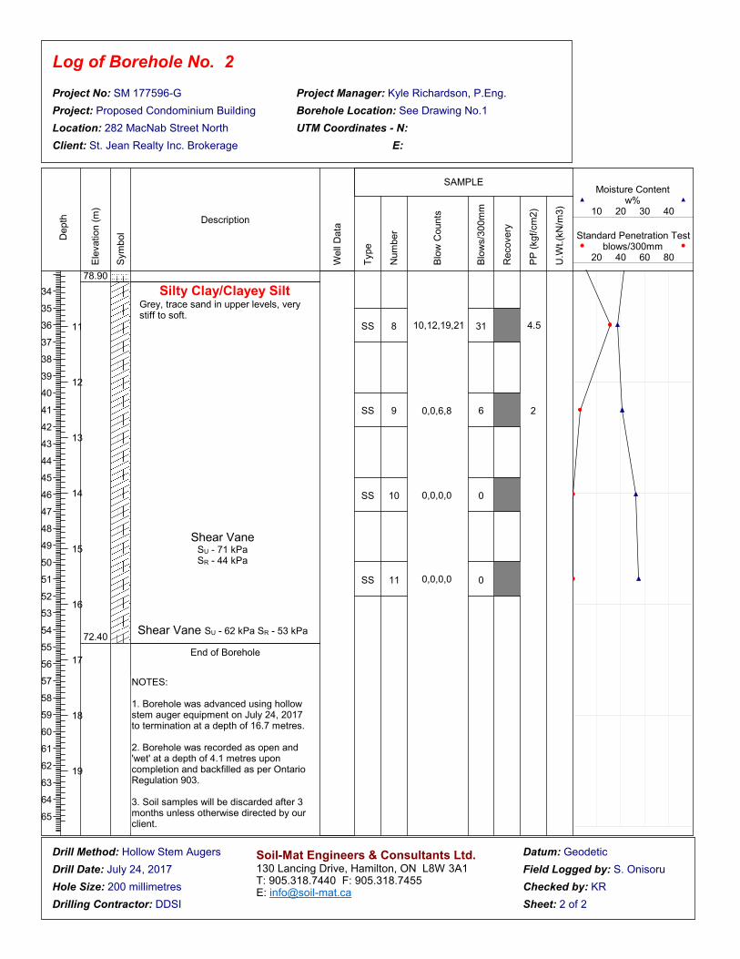
78.90
72.40
Silty Clay/Clayey SiltGrey, trace sand in upper levels, very stiff to soft.
End of Borehole
SS
SS
SS
SS
8
9
10
11
10,12,19,21
0,0,6,8
0,0,0,0
0,0,0,0
31
6
0
0
4.5
2
Hollow Stem Augers
July 24, 2017
200 millimetres
DDSI
Geodetic
S. Onisoru
KR
NOTES:
1. Borehole was advanced using hollow stem auger equipment on July 24, 2017 to termination at a depth of 16.7 metres.
2. Borehole was recorded as open and 'wet' at a depth of 4.1 metres upon completion and backfilled as per Ontario Regulation 903.
3. Soil samples will be discarded after 3 months unless otherwise directed by our client.
Shear Vane SU - 71 kPaSR - 44 kPa
Shear Vane SU - 62 kPa SR - 53 kPa

Log of Borehole No.
Project No:
Project:
Location:
Client:
Project Manager:
Borehole Location:
UTM Coordinates - N:
E:
Drill Method:
Drill Date:
Hole Size:
Drilling Contractor:
Datum:
Field Logged by:
Checked by:
Sheet: 1 of 3
Depth
0 0ft m
1
1
2
2
3
3
4
4
5
5
6
6
7
7
8
8
9
9
10
11
12
13
14
15
16
17
18
19
20
21
22
23
24
25
26
27
28
29
30
31
32
33
Ele
vation (
m)
Sym
bol
Description
Well
Data
Type
Num
ber
Blo
w C
ounts
Blo
ws/3
00m
m
Recovery
PP
(kgf/
cm
2)
U.W
t.(k
N/m
3)
Moisture Content w%
10 20 30 40
Standard Penetration Test blows/300mm
20 40 60 80
SAMPLE
Soil-Mat Engineers & Consultants Ltd.130 Lancing Drive, Hamilton, ON L8W 3A1T: 905.318.7440 F: 905.318.7455 E: [email protected]
3
SM 177596-G
Proposed Condominium Building
282 MacNab Street North
St. Jean Realty Inc. Brokerage
Kyle Richardson, P.Eng.
See Drawing No.1
88.88 Ground Surface
Pavement StructureApproximately 150 millimetres of concrete.
Silty Sand/Sandy SiltRedish brown, occasional clay inclusions, very loose to compact.
SS
SS
SS
SS
SS
SS
SS
1
2
3
4
5
6
7
0,0,0,0
0,0,0,0
1,2,2,2
6,5,6,6
6,8,12,16
1,1,1,1
7,8,14,10
0
0
4
11
20
2
22
Hollow Stem Augers
July 21, 2017
200 millimetres
DDSI
Geodetic
S. Onisoru
KR

Log of Borehole No.
Project No:
Project:
Location:
Client:
Project Manager:
Borehole Location:
UTM Coordinates - N:
E:
Drill Method:
Drill Date:
Hole Size:
Drilling Contractor:
Datum:
Field Logged by:
Checked by:
Sheet: 2 of 3
Depth
11
12
13
14
15
16
17
18
19
34
35
36
37
38
39
40
41
42
43
44
45
46
47
48
49
50
51
52
53
54
55
56
57
58
59
60
61
62
63
64
65
Ele
vation (
m)
Sym
bol
Description
Well
Data
Type
Num
ber
Blo
w C
ounts
Blo
ws/3
00m
m
Recovery
PP
(kgf/
cm
2)
U.W
t.(k
N/m
3)
Moisture Content w%
10 20 30 40
Standard Penetration Test blows/300mm
20 40 60 80
SAMPLE
Soil-Mat Engineers & Consultants Ltd.130 Lancing Drive, Hamilton, ON L8W 3A1T: 905.318.7440 F: 905.318.7455 E: [email protected]
3
SM 177596-G
Proposed Condominium Building
282 MacNab Street North
St. Jean Realty Inc. Brokerage
Kyle Richardson, P.Eng.
See Drawing No.1
78.70
Silty Clay/Clayey SiltGrey, trace sand in upper levels, very soft to very stiff.
SS
SS
SS
SS
8
9
10
11
4,6,20,9
0,0,0,0
0,0,0,0
0,0,0,1
26
0
0
0
2
Hollow Stem Augers
July 21, 2017
200 millimetres
DDSI
Geodetic
S. Onisoru
KR
Shear Vane SU - 53 kPaSR - 35 kPa
Shear Vane SU - 71 kPaSR - 53 kPa

Log of Borehole No.
Project No:
Project:
Location:
Client:
Project Manager:
Borehole Location:
UTM Coordinates - N:
E:
Drill Method:
Drill Date:
Hole Size:
Drilling Contractor:
Datum:
Field Logged by:
Checked by:
Sheet: 3 of 3
Depth
21
22
23
24
25
26
27
28
29
66
67
68
69
70
71
72
73
74
75
76
77
78
79
80
81
82
83
84
85
86
87
88
89
90
91
92
93
94
95
96
97
98
Ele
vation (
m)
Sym
bol
Description
Well
Data
Type
Num
ber
Blo
w C
ounts
Blo
ws/3
00m
m
Recovery
PP
(kgf/
cm
2)
U.W
t.(k
N/m
3)
Moisture Content w%
10 20 30 40
Standard Penetration Test blows/300mm
20 40 60 80
SAMPLE
Soil-Mat Engineers & Consultants Ltd.130 Lancing Drive, Hamilton, ON L8W 3A1T: 905.318.7440 F: 905.318.7455 E: [email protected]
3
SM 177596-G
Proposed Condominium Building
282 MacNab Street North
St. Jean Realty Inc. Brokerage
Kyle Richardson, P.Eng.
See Drawing No.1
64.5064.29 Queenston Shale
Red, highly weathered in upper levels, becoming more sound with depth, hard.
End of Borehole
SS
SS
12
13
0,0,0,2
50/1"
0
100
Hollow Stem Augers
July 21, 2017
200 millimetres
DDSI
Geodetic
S. Onisoru
KR
NOTES:
1. Borehole was advanced using hollow stem auger equipment on July 21, 2017 to termination at a depth of 24.6 metres.
2. Borehole was recorded as open and 'dry' upon completion and backfilled as per Ontario Regulation 903.
3. Soil samples will be discarded after 3 months unless otherwise directed by our client.
Shear Vane SU - 125 kPaSR - 97 kPa
Silty Clay/Clayey SiltGrey, trace sand in upper levels, very soft to very stiff.

DRAWING No. 2Soil-Mat
Project No.:
Date:
SM 177596-G
August 2017
GROUND SURFACE
NOT TO SCALEpour flush with original undisturbed soil
SUBGRADEcompetent natural soilor well compacted fill
sloped away from building
FLOOR SLAB
MOISTURE BARRIERMinimum 200mm clear crushed stone,well compacted.
SUBSURFACE WALLSuitably damp proofed / water proofed and drainage board.
Soil-Mat Engineers & Consultants Ltd.
FOOTING/GRADE BEAM
EXCAVATION SHORINGAs per design by shoring engineer.
WATERPROOF MEMBRANEWATER STOP
Typical Design RequirementsWater Tight Basement Foundations

DRAWING No. 3Soil-MatTypical Design Requirements
Drainage and Backfill for Exterior WallsIncluding Underfloor Drains
Project No.:
Date:
SM 177596-G
August 2017
GROUND SURFACE
NOT TO SCALEpour flush with original undisturbed soil
SUBGRADEGeofabric encased 150mm diameter perforated weeping tile or pipe equivalent, leading to positive sump or outlet. Invert at least 300mm below underside of floor slab. Pipeplaced in parallel rows on nominal 6m centres.
UNDERFLOOR DRAINcompetent natural soilor well compacted fill
sloped away from building
FLOOR SLAB
MOISTURE BARRIERMinimum 200mm clear crushed stone,well compacted.
SUBSURFACE WALLSuitably damp proofed / water proofed and drainage board.
Soil-Mat Engineers & Consultants Ltd.
CLEAR STONE19mm clear stone, minimum 300mm belowand sides of pipe, encased in filter fabric.
VAPOUR BARRIERWhere 'non damp' floors are required,provide heavy 'poly' sheeting or membrane.
FOOTING/GRADE BEAM
CLEAR STONE20mm clear stone, minimum 150mm top and sides of drain, encased in heavy geofabric.
PERIMETER DRAINFilter fabric encased 150mm diameter perforated pipe, leading to positive sump or outlet. Invert at least 150mm below underside of floor slab.
EXCAVATION SHORINGAs per design by shoring engineer.